

Page 1

PARTS AND OPERATION MANUAL
OPERATION AND PARTS MANUAL
MODEL DCA-800SSK
PORTABLE GENERATOR
(STANDARD)
Revision #4 (06/03/10)
To find the latest revision of this
publication, visit our website at:
www.mqpower.com
THIS MANUAL MUST ACCOMPANY THE EQUIPMENT AT ALL TIMES.
Page 2

Diesel engine exhaust and some of
PAGE 2 — DCA-800SSK (STD) — OPERATION AND PARTS MANUAL — REV. #4 (06/03/10)
Page 3

DCA-800SSK (STD) — OPERATION AND PARTS MANUAL — REV. #4 (06/03/10) — PAGE 3
Page 4

DCA-800SSK TABLE OF CONTENTS
MQ Power DCA-600SSKMQ Power DCA-600SSK
MQ Power DCA-600SSK
MQ Power DCA-600SSKMQ Power DCA-600SSK
AC GeneratorAC Generator
AC Generator
AC GeneratorAC Generator
Here's How To Get Help .................................................... 3
Parts Ordering Procedures ............................................... 5
Specifications Generator/Engine ...................................... 6
Dimensions (Top and Side) ............................................... 8
Dimensions (Front and Rear) ............................................ 9
Safety Alert Messages Symbols ............................... 10-11
Rules for Safe Operation ........................................... 12-15
Installation ................................................................. 16-17
Towing Rules for Safe Operation .................................... 18
Trailer Safety Guidelines ................................................. 19
Trailer Specifications ................................................. 20-21
Operation and Safety Decals ..................................... 22-25
General Information ........................................................ 26
Major Components ......................................................... 27
Generator Control Panel (Up to S/N 3698616) ................ 28
Generator Control Panel (S/N 3698617~)........................ 28
Generator Control Panel Description ............................... 29
Engine Operating Panel (Up to S/N 3698616) ................. 30
Engine Operating Panel (S/N 3698617~) ........................ 30
Engine Operating Panel Description ............................... 31
Output Terminal Panel Overview ................................ 32-34
Load Application ............................................................. 35
Generator Outputs .......................................................... 36
Generator Outputs/Gauge Reading ................................. 37
Output Terminal Panel Connections ........................... 38-39
Pre Setup .................................................................. 40-44
Generator Start-up Procedure (Key Switch) .............. 45-47
Generator Start-up Procedure ( Manual MPEC) ............. 48
Generator Start-up Procedure (Auto MPEC) .................. 49
Generator Shutdown Procedure ...................................... 50
Maintenance .............................................................. 51-55
Trailer Brakes Maintenance ............................................ 56
Trailer Maintenance .................................................... 57-58
Trailer Wiring Diagrams .............................................. 59-60
Generator Wiring Diagram ............................................... 61
Generator Main breaker Wiring Diagram ......................... 62
Engine Wiring Diagrams ............................................ 63-64
Electronic Governor Controller Wiring Diagram ............... 65
Engine Troubleshooting .............................................. 66-67
Generator Troubleshooting .............................................. 68
Engine Contoller Troubleshooting (MPEC) ...................... 69
Explanation of Codes in Remarks Column ..................... 70
Suggested Spare Parts .................................................. 71
COMPONENT DRACOMPONENT DRA
COMPONENT DRA
COMPONENT DRACOMPONENT DRA
Generator Assembly .......................................... 72-75
Control Box Assembly ........................................ 76-81
Engine and Radiator Assembly .......................... 82-85
Oil Drain Assembly ............................................. 86-87
Engine Operating Panel Assembly .................... 88-89
Output Terminal Assembly ................................. 90-93
Battery Assembly ............................................... 94-95
Muffler Assembly ............................................... 96-97
Fuel Tank Assembly ........................................... 98-99
Enclosure #1 Assembly.................................. 100-103
Enclosure #2 Assembly.................................. 104-107
Enclosure #3 Assembly.................................. 108-111
Enclosure (Rubber Seals) .............................. 112-113
Name Plate and Decals ................................. 114-117
Terms and Conditions Of Sale — Parts ................ 118
NOTE
Specification and part
number are subject to
change without notice.
WINGSWINGS
WINGS
WINGSWINGS
PAGE 4 — DCA-800SSK (STD) — OPERATION AND PARTS MANUAL — REV. #4 (06/03/10)
Page 5
PARTS ORDERING PROCEDURES
Ordering parts has never been easier!
Choose from three easy options:
January 1
Effective:
st
, 2006
Best Deal!
Order via Internet (Dealers Only):
Order parts on-line using Multiquip’s SmartEquip website!
N View Parts Diagrams
N Order Parts
N Print Specification Information
Goto www.multiquip.com and click on
Order Parts
Order via Fax (Dealers Only):
All customers are welcome to order parts via Fax.
Domestic (US) Customers dial:
1-800-6-PARTS-7 (800-672-7877)
Non-Dealer Customers:
Contact your local Multiquip Dealer for
parts or call 800-427-1244 for help in
locating a dealer near you.
to log in and save!
Order via Phone:
If you have an MQ Account, to obtain a Username
and Password, E-mail us at: parts@multiquip.
com.
To obtain an MQ Account, contact your
District Sales Manager for more information.
Use the internet and qualify for a 5% Discount
on Standard orders for all orders which include
complete part numbers.*
Note: Discounts Are Subject To Change
Fax your order in and qualify for a 2% Discount
on Standard orders for all orders which include
complete part numbers.*
Note: Discounts Are Subject To Change
Domestic (US) Dealers Call:
1-800-427-1244
International Customers should contact
their local Multiquip Representatives for
Parts Ordering information.
R Dealer Account Number
R Dealer Name and Address
R Shipping Address (if different than billing address)
R Return Fax Number
R Applicable Model Number
R Quantity, Part Number and Description of Each Part
www.mqpower.com
DCA-800SSK (STD) — OPERATION AND PARTS MANUAL — REV. #4 (06/03/10) — PAGE 5
When ordering parts, please supply:
R Specify Preferred Method of Shipment:
UPS/Fed Ex DHL
N Priority One Tr uck
N Ground
N Next Day
N Second/Third Day
NOTICE
All orders are treated as Standard Orders and will
ship the same day if received prior to 3PM PST.
WE ACCEPT ALL MAJOR CREDIT CARDS!
Page 6
DCA-800SSK — SPECIFICATIONS
ledoMKSS008-ACD
snoitacificepS.7elbaT
snoitacificepSrotareneG
epyT
rAlartueNhtiwratS
esahP3
deepSmpr0081
noitcennoCerutam
tuptuOybdnatS)WK047(AVK088
tuptuOemirP)WK046(AVK008
egatloV
ycneuqerFzH06
rotcaFrewoP8.
)A(BdleveLdnuoS)teef32tadaollluf(37
ledoM041V21VSUSTAMOK
suonorhcnysepytdetcetorpnepo,detalitnevfles,dleifgnivloveR
rotareneg
044,614,042,022,802
0
)esahp3(elbatcennocer084,
)esahpelgnis(elbatsujda772,452,042,931,721,0021
snoitacificepSenignE
epyT relooc-retfahtiwdegrahc-obrut,noitcejnitcerid
srednilyCfo.oNsrednilyc21
oB )mm561xmm041(.ni5.6x.ni5.5
PAGE 6 — DCA-800SSK (STD) — OPERATION AND PARTS MANUAL — REV. #4 (06/03/10)
ekortSxer
tuptuOdetaRmpr0081/PH689
tnemecalpsiD)cc08403(.ni.uc8581
gnitratScirtcelE
ytica
paCtnalooC)sretil361(.lag54
yticapaCliOebuL)sretil0.151(.lag04
tarh/)L361(.lag34 daollluf ta
noitpmusnoCleuF
tarh/)L6.78(.lag1.32 daol2/1 tarh/)L4.65(.lag9.41 daol4/1
yrettaB4xHA002-V21
leuFleu
FleseiD2#
rh/)L021(.lag7.13 daol4/3
Page 7

NOTE PAGE
DCA-800SSK (STD) — OPERATION AND PARTS MANUAL — REV. #4 (06/03/10) — PAGE 7
Page 8
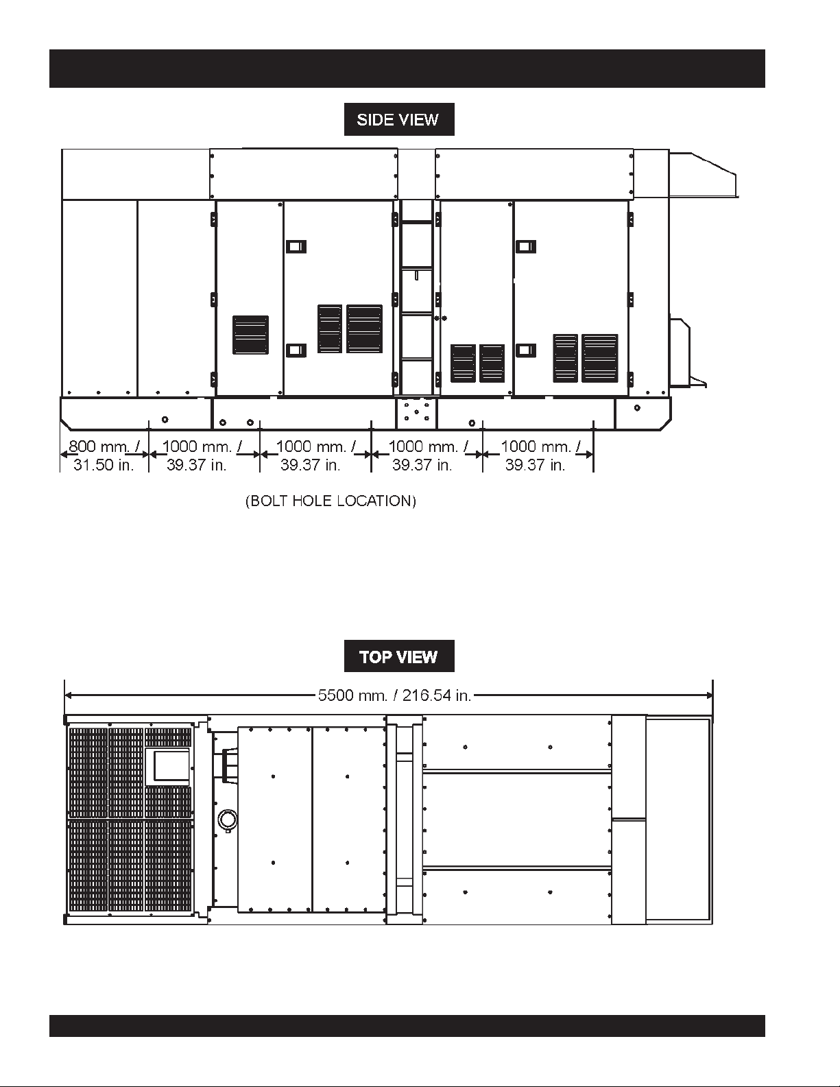
DCA-800SSK — DIMENSIONS (TOP AND SIDE)
Figure 1. Dimensions
PAGE 8 — DCA-800SSK (STD) — OPERATION AND PARTS MANUAL — REV. #4 (06/03/10)
Page 9
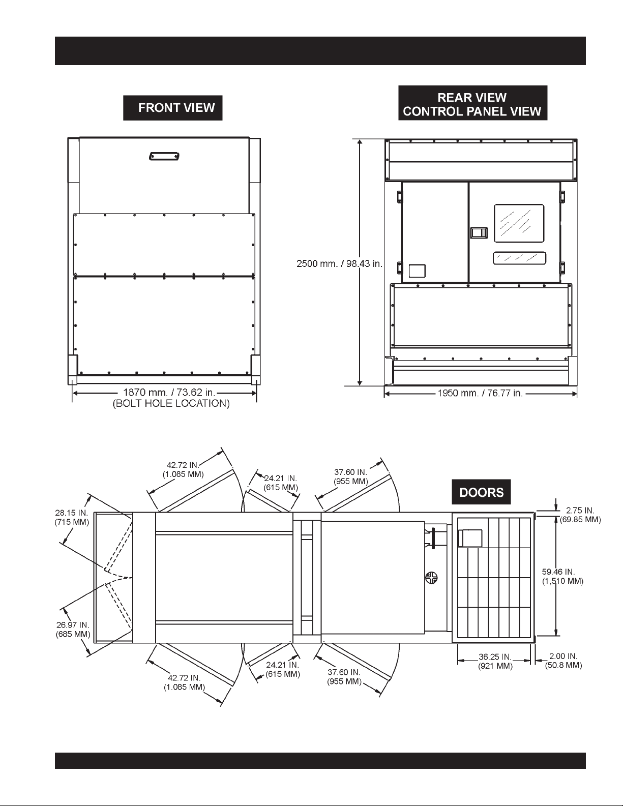
DCA-800SSK— DIMENSIONS (FRONT , REAR AND DOORS)
Figure 2. Dimensions
DCA-800SSK (STD) — OPERATION AND PARTS MANUAL — REV. #4 (06/03/10) — PAGE 9
Page 10
DCA-800SSK — SAFETY MESSAGE ALERT SYMBOLS
FOR YOUR SAFETY AND THE SAFETY OF OTHERS!
Safety precautions should be followed at all times when
operating this equipment. Failure to read and understand the
Safety Messages and Operating Instructions could result in
injury to yourself and others.
This
NOTE
Operation and Parts
has been developed to provide
complete instructions for the safe
and efficient operation of the MQ
Power
Model DCA-800SSK (60Hz)
Manual
HAZARD SYMBOLS
Potential hazards associated with the operation of this
equipment will be referenced with "
appear throughout this manual, and will be referenced in
conjunction with Safety "
WARNING - LETHAL EXHAUST GASES
Whisperwatt™ Generator.
Before using this generator, ensure that the operating
individual has read and understands all instructions in
this manual.
SAFETY MESSAGE ALERT SYMBOLS
The three (3) Safety Messages shown below will inform you
about potential hazards that could injure you or others. The
Safety Messages specifically address the level of exposure
to the operator, and are preceded by one of three words:
DANGER, WARNING, or CAUTION.
DANGER
You WILL be KILLED or SERIOUSLY injured if you
do not follow directions.
equipment in a confined area or enclosed structure that
does not provide ample free flow air.
WARNING - EXPLOSIVE FUEL
DO NOT overfill tank, since spilled fuel could ignite if it
comes into contact with hot engine parts or sparks from
the ignition system. Store fuel in approved containers, in
well-ventilated areas and away from sparks and flames.
NEVER use fuel as a cleaning agent.
Hazard Symbols
Message Alert Symbols
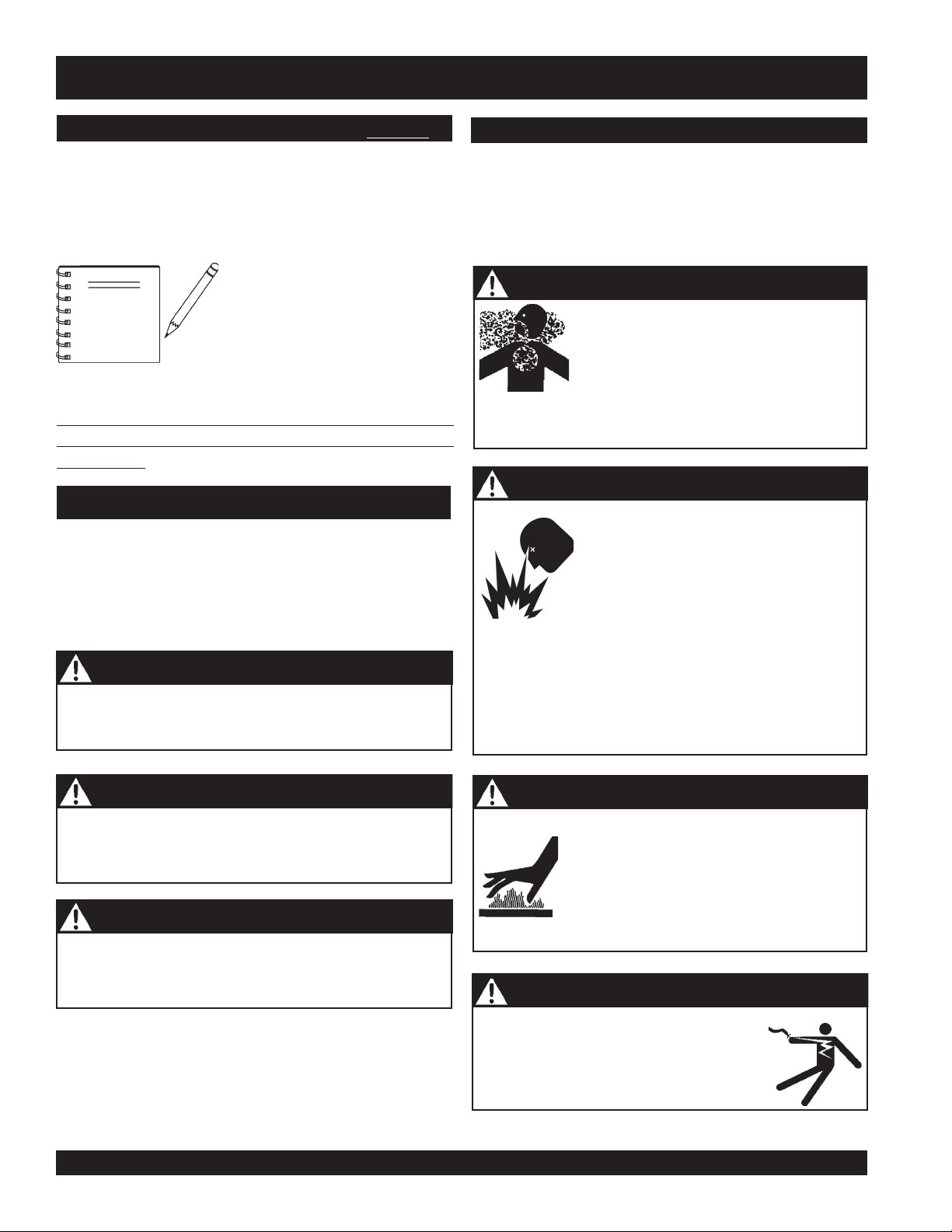
Gasoline engine exhaust gases contain
poisonous carbon monoxide. This gas is
colorless and odorless, and can cause
DEATH
if inhaled. NEVER operate this
Gasoline
its vapors can cause an explosion if
ignited. DO NOT start the engine near
spilled fuel or combustible fluids.
DO NOT fill the fuel tank while the engine
is running or hot.
is extremely flammable, and
" which
".
WARNING
You COULD be KILLED or SERIOUSLY injured if
you do not follow directions.
CAUTION
You CAN be injured if you do not follow directions
PAGE 10 — DCA-800SSK (STD) — OPERATION AND PARTS MANUAL — REV. #4 (06/03/10)
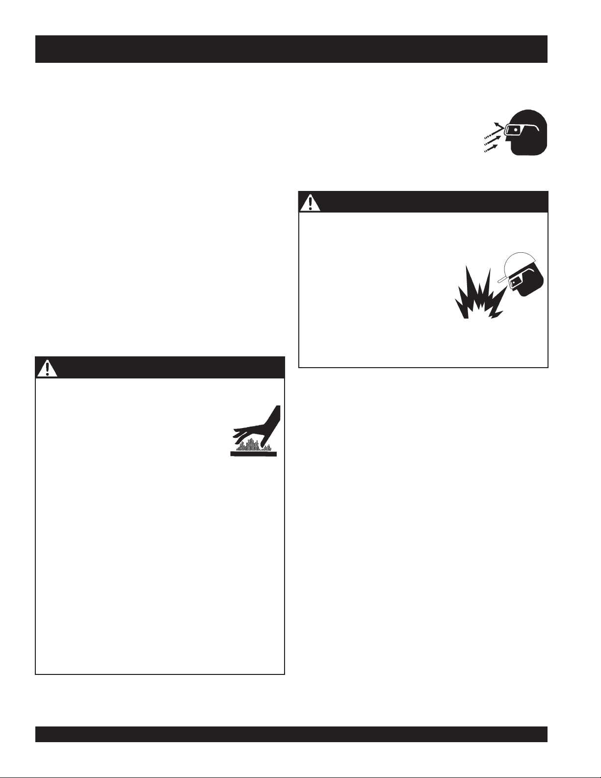
WARNING - BURN HAZARDS
Engine components can generate extreme
heat. To prevent burns, DO NOT touch these
areas while the engine is running or
immediately after operations. NEVER
operate the engine with heat shields or heat
guards removed.
DANGER - ELECTROCUTION HAZARDS
During operation of this generator, there
exists the possibility of
electrical shock or burn,
severe bodily harm
electrocution,
which can cause
or even
DEATH!
Page 11
DCA-800SSK — SAFETY MESSAGE ALERT SYMBOLS
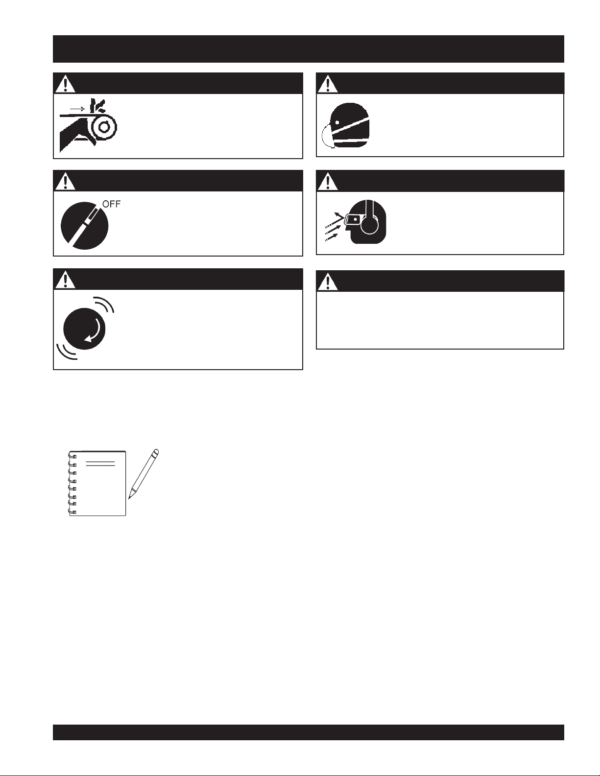
WARNING - ROTATING PARTS
NEVER operate equipment with covers,
or guards removed. Keep
hair
and clothing away from all moving
parts to prevent injury.
CAUTION - ACCIDENTAL STARTING
ALWAYS place the engine ON/OFF
switch in the OFF position when the
generator is not in use.
CAUTION - OVER-SPEED CONDITIONS
NEVER tamper with the factory settings
of the engine governor or settings.
Personal injury and damage to the engine
or equipment can result if operating in
speed ranges above maximum allowable.
fingers, hands
CAUTION - RESPIRATORY HAZARDS
,
CAUTION - SIGHT AND HEARING HAZARDS
CAUTION - EQUIPMENT DAMAGE MESSAGES
Other important messages are provided throughout this
manual to help prevent damage to your generator, other
property, or the surrounding environment.
ALWAYS wear approved
protection.
ALWAYS wear approved
hearing
protection.
respiratory
eye
and
This generator, other property,
NOTE
DCA-800SSK (STD) — OPERATION AND PARTS MANUAL — REV. #4 (06/03/10) — PAGE 11
or the surrounding environment
could be damaged if you do not
follow instructions.
Page 12
DCA-800SSK — RULES FOR SAFE OPERATION
■
DANGER - READ THIS MANUAL!
Failure to follow instructions in this manual may lead to
serious injury
operated by trained and qualified personnel only! This
equipment is for industrial use only.
The following safety guidelines should always be used when
operating the DCA-800SSK
or even
DEATH
! This equipment is to be
(60 Hz) Whisperwatt
™
Generator
General Safety:
■
DO NOT operate or service this
equipment before reading this entire
manual.
The operator MUST BE familiar with proper safety
precautions and operations techniques before using
generator.
■
This equipment should not be operated by persons under
18 years of age.
■
NEVER operate this equipment without proper protective
clothing, shatterproof glasses, steel-toed boots and other
ALWAYS check the machine for loosened threads or bolts
before starting.
■
NEVER operate the generator in an explosive atmosphere
or near combustible materials. An explosion or fire could
result causing severe
■
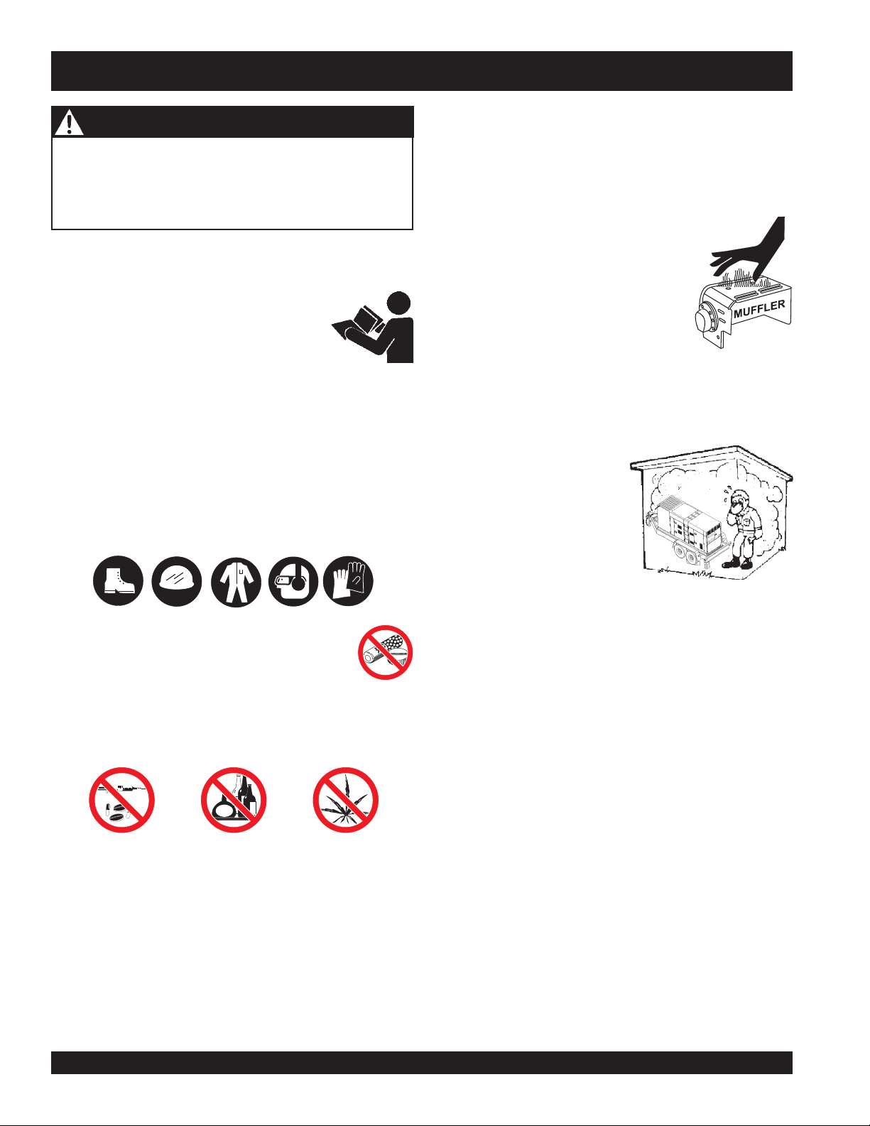
NEVER touch the hot exhaust manifold, muffler
or cylinder. Allow these parts to cool before
servicing engine or generator.
■
High Temperatures – Allow the engine
to cool before performing service and
maintenance functions. Contact with
hot!
components can cause serious
burns.
■
The engine of this generator requires an adequate free
flow of cooling air.
enclosed or narrow area where free flow of the air is
restricted. If the air flow is
restricted it will cause serious
damage to the generator or
engine and may cause injury
to people. The generator
engine gives off DEADLY
carbon monoxide gas.
bodily harm or even death.
NEVER
operate the generator in any
■
protective devices required by the job.
■
NEVER operate this equipment when not
feeling well due to fatigue, illness or taking
medicine.
■
NEVER operate this equipment under the influence or
drugs or alcohol.
■
NEVER use accessories or attachments, which are not
recommended by MQ Power for this equipment. Damage
to the equipment and/or injury to user may result.
■
Manufacturer does not assume responsibility for any
accident due to equipment modifications. Unauthorized
equipment modification will void all warranties.
■
Whenever necessary, replace nameplate, operation and
safety decals when they become difficult read.
■
■
■
■
DO NOT place hands or fingers inside generator engine
compartment when engine is running.
NEVER run engine without air filter. Severe engine damage
may occur.
DO NOT leave the generator running in the
unattended.
Refer to the
engine technical questions or information.
ALWAYS store equipment properly when it is not being
used. Equipment should be stored in a clean, dry location
out of the reach of children.
Komatsu Engine Owner's Manual
manual mode
for
PAGE 12 — DCA-800SSK (STD) — OPERATION AND PARTS MANUAL — REV. #4 (06/03/10)
Page 13
DCA-800SSK — RULES FOR SAFE OPERATION
Generator Grounding
DANGER - ELECTROCUTION HAZARDS
To guard against electrical shock and possible damage to
the equipment, it is important to provide a good EARTH
ground.
During operation of this generator, there
exists the possibility of
electrical shock or burn,
Article 250 (Grounding) of the
National Electrical Code
severe bodily harm
(NEC) provides guide lines for proper grounding and specifies
that the cable ground shall be connected to the grounding
system of the building as close to the point of cable entry
as practical.
The following safety recommendations should also be
followed:
To avoid these hazards:
NEVER use damaged or worn cables when connecting
equipment to the generator. Make sure power connecting
cables are securely connected to the generator’s output
terminals, insufficient tightening of the terminal connections
may cause damage to the generator
■
ALWAYS make sure generator is properly grounded.
■
NEVER use gas piping as an electrical ground.
■
ALWAYS make sure that electrical circuits are properly
grounded
local codes before operating generator. Severe
DEATH!
per the
National Electrical Code
(NEC) and
injury
by electrocution can result from operating an
ungrounded generator.
■
ALWAYS be sure to use the ground terminal (green wire)
when connecting a load to the U,V, and W output
terminal lugs.
or
and electrical shock.
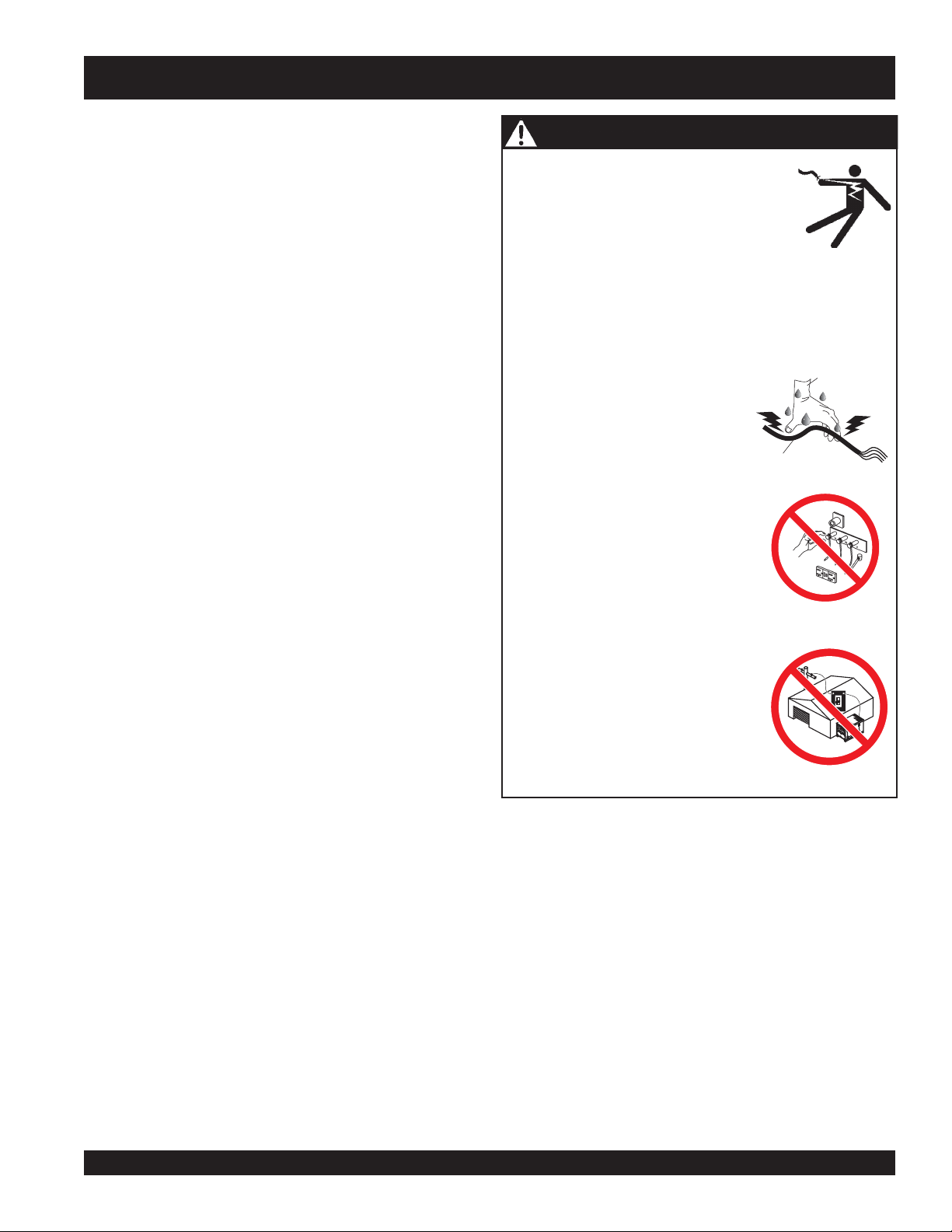
NEVER grab or touch a live power
cord with wet hands.
NEVER touch output terminals
during operation. This is extremely
dangerous. ALWAYS stop the
machine and place the circuit
breaker in the OFF position when
contact with the output terminals is
required.
electrocution,
which can cause
or even
DEATH!
POWER
CORD
(POWER ON)
WET
HANDS
Electrical Safety
■
ALWAYS have a qualified electrician perform the
generator wiring installation.
■
ALWAYS make sure generator installation is accordance
with the
National Electrical Code
(NEC) and local codes
before operating generator.
■
NEVER use a defective or frayed power cable. Check
the cable for cuts in the insulation.
■
NEVER use a extension cord that is frayed or damaged
where the insulation has been cut.
■
ALWAYS make certain that proper extension cord has
been selected for the job. See Table 6.
■
NEVER power cables or cords
■
NEVER
stand in water
while AC power from the generator
lay in wate
r.
is being transfer to a load.
Backfeed to a utility system can
cause
electrocution
and or property
damage. DO NOT connect to any
building's electrical system except
through an approved device or after
building main switch is opened.
ALWAYS have a licensed electrician
perform the installation
DCA-800SSK (STD) — OPERATION AND PARTS MANUAL — REV. #4 (06/03/10) — PAGE 13
Page 14
DCA-800SSK — RULES FOR SAFE OPERATION
Maintenance Safety
■
The electrical voltage required to operate the generator
can cause severe injury or even death through physical
contact with live circuits.
before performing maintenance on the generator.
■
NEVER lubricate components or attempt service on a
running machine.
■
ALWAYS disconnect the
before performing service on the generator.
■
Follow all Battery Safety Guidelines listed in this manual
when handling or servicing the generator.
■
ALWAYS allow the machine a proper amount of time to
cool before servicing.
■
Keep the machinery in proper running condition.
■
Fix damage to the machine immediately and always
replace broken parts.
■
ALWAYS service air cleaner frequently to prevent engine
malfunction.
WARNING - BURN HAZARDS
To prevent burns, DO NOT touch or open any of the below
mentioned components while the engine is
running or immediately after operations.
Always allow sufficient time for the engine
and generator to cool before performing
maintenance.
■
Radiator Cap - Removing the radiator cap while the
engine is hot will result in high pressurized, boiling water
to gush out of the radiator, causing severe scalding to
any persons in the general area of the generator.
■
Coolant Drain Plug - Removing the coolant drain plug
while the engine is hot will result in hot coolant gushing
out of the coolant drain plug, therefore causing severe
scalding to any persons in the general area of the
generator.
Turn all circuit breakers OFF
NEGATIVE battery terminal
Battery Safety
Use the following guidelines when handling the battery:
■
■
■■
■
■■
■■
■
■■
■■
■
■■
■■
■
■■
■■
■
■■
The battery contains acids that can
cause injury to the eyes and skin. To
avoid eye irritation,
safety glasses.
Use well insulated gloves when picking up the battery.
DANGER - EXPLOSION HAZARDS
The risk of an explosion exists when performing service
on the battery. To avoid
■■
■
DO NOT drop the battery. There
■■
is the possibility of risk that the
battery may explode.
■■
■
DO NOT expose the battery to
■■
open flames, sparks, cigarettes
etc. The battery contains combustible gases and liquids.
If these gases and liquids come in contact with a flame
or spark, an explosion could occur.
ALWAYS keep the battery charged. If the battery is not
charged a buildup of combustible gas will occur.
ALWAYS keep battery charging and cables in good
working condition. Repair or replace all worn cables.
ALWAYS recharge the battery in an vented air
environment, to avoid risk of a dangerous concentration
of combustible gases.
In case the battery liquid (dilute sulfuric acid) comes in
contact with
immediately with plenty of water.
In case the battery liquid (dilute sulfuric acid) comes in
contact with your
plenty of water and contact the nearest doctor or hospital
to seek medical attention.
clothing or skin
always
severe injury
EYES
wear
or
DEATH:
, rinse skin or clothing
, rinse eyes immediately with
■
Engine Oil Drain Plug - Removing the engine oil drain
plug while the engine is hot will result in hot oil gushing
out of the oil drain plug, therefore causing severe
scalding to any persons in the general area of the
generator.
PAGE 14 — DCA-800SSK (STD) — OPERATION AND PARTS MANUAL — REV. #4 (06/03/10)
Page 15
DCA-800SSK — RULES FOR SAFE OPERATION
Towing & Transporting Safety
To reduce the possibility of an accident while transporting
the generator on public roads, always make sure the trailer
that supports the generator and the towing vehicle are in
good operating condition and both units are mechanically
sound.
The following list of safety precautions should be followed
when towing your generator:
CAUTION - FOLLOW TOWING REGULATIONS
Check with your local county or state safety towing
regulations, in addition to meeting
Transportation
towing your generator.
■
ALWAYS shutdown engine before transporting.
■
Tighten both fuel tank caps securely.
■
If generator is mounted on a trailer, make sure trailer
complies with all local and state safety transportation
laws. Follow the listed
guidelines for basic towing techniques.
■
Make sure the hitch and coupling of the towing vehicle
are rated equal to, or greater than the trailer "gross vehicle
weight rating.”
■
ALWAYS inspect the hitch and coupling for wear. NEVER
tow a trailer with defective hitches, couplings, chains etc.
■
Check the tire air pressure on both towing vehicle and
trailer.
Also check the tire tread wear on both vehicles.
■
ALWAYS make sure the trailer is equipped with a "Safety
Chain".
■
ALWAYS attach trailer’s safety chains to towing vehicle
properly.
■
ALWAYS make sure the vehicle and trailer directional,
backup, brake, and trailer lights are connected and
working properly.
■
DOT Requirements include the following:
Connect and test electric brake operation.
Secure portable power cables in cable tray with tie
wraps.
(DOT)
Safety Towing Regulations
Towing & Transporting Safety
Trailer tires should be inflated to 50 psi cold.
Department of
, before
■
The maximum speed for highway towing is 55 MPH
unless posted otherwise. Recommended off-road towing
is not to exceed 15 MPH or less depending on type of
terrain.
■
Place
while parked.
■
Use the trailer’s swivel jack to adjust the trailer height to
a level position while parked.
■
Avoid sudden stops and starts. This can cause skidding,
or jack-knifing. Smooth, gradual starts and stops will
improve towing.
■
Avoid sharp turns.
■
Trailer should be adjusted to a level position at all times
when towing.
■
Raise and lock trailer wheel stand in up position when
transporting.
■
The maximum speed for highway towing is 55 MPH
unless posted otherwise. Recommended off-road towing
is not to exceed 15 MPH or less depending on type of
terrain.
■
Place
prevent tipping, while parked.
■
Avoid sharp turns to prevent rolling.
■
DO NOT transport generator with fuel in tank.
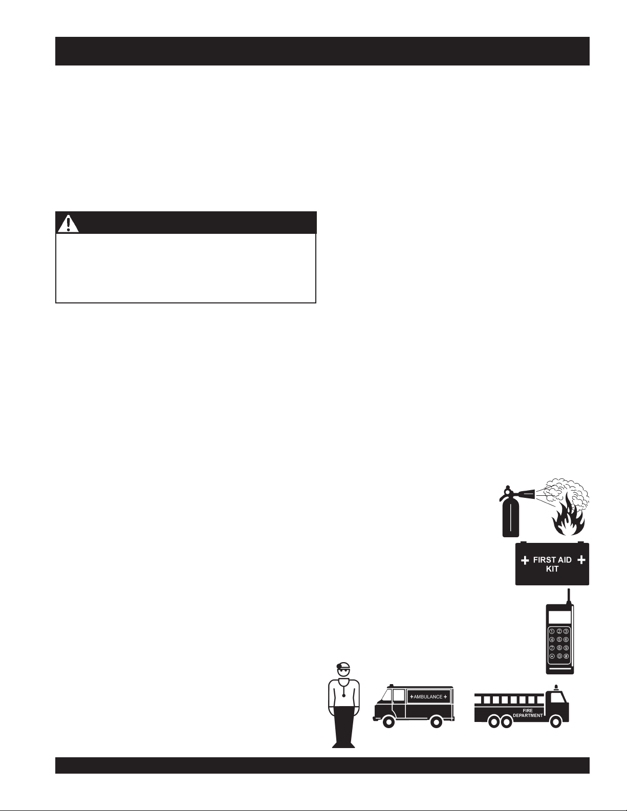
Emergencies
■
ALWAYS know the location of the
nearest
■
ALWAYS know the location of the
nearest and
■
ALWAYS know the location of the
nearest phone or
the job site,
■
ALWAYS have easy access to the phone
numbers of the nearest
and
Fire Department
be invaluable in the case of an emergency.
chock blocks
support blocks
fire extinguisher
underneath wheel to prevent rolling,
underneath the trailer’s bumper to
.
first aid kit
.
keep a phone on
in case of emergencies.
Ambulance, Doctor
. This information will
DCA-800SSK (STD) — OPERATION AND PARTS MANUAL — REV. #4 (06/03/10) — PAGE 15
Page 16
DCA-800SSK — INSTALLATION
DCA-600SSK — INSTALLATION
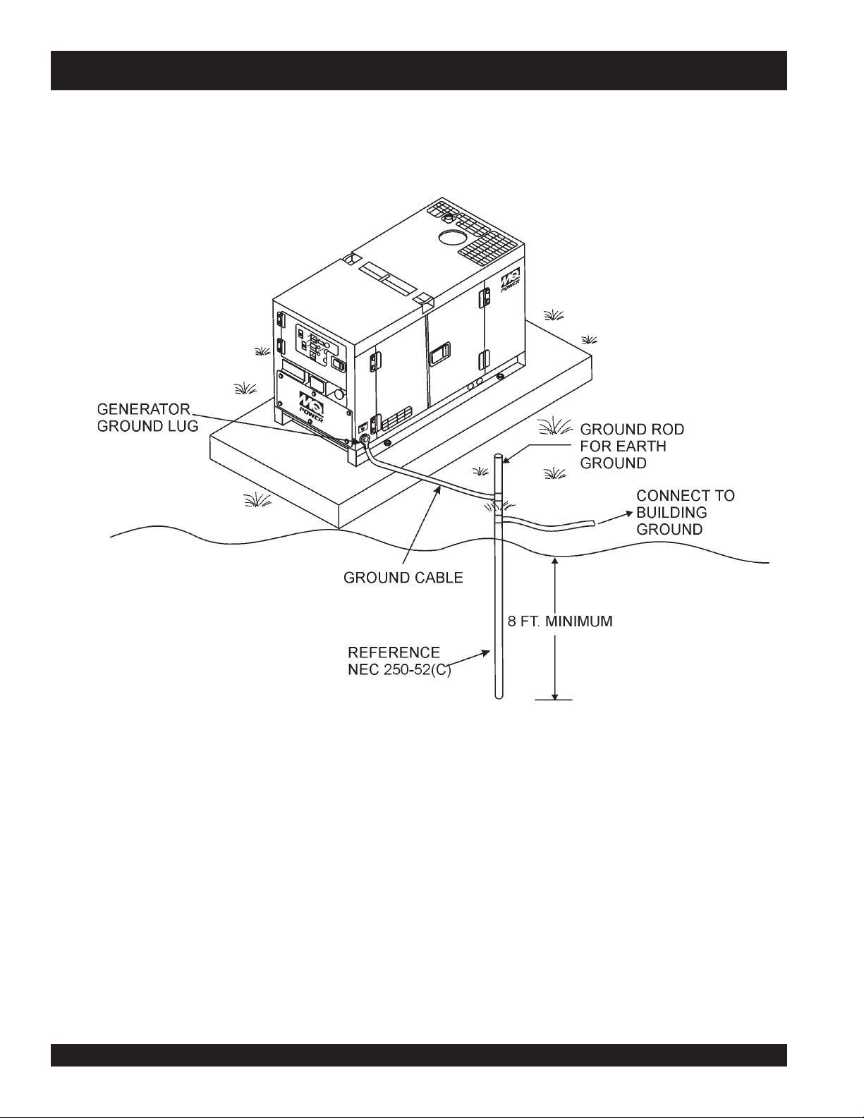
Figure 3. Typical Generator Grounding Application
PAGE 16 — DCA-800SSK (STD) — OPERATION AND PARTS MANUAL — REV. #4 (06/03/10)
Page 17
DCA-800SSK — INSTALLATION
Outdoor Installation
Install the generator in a area that is free of
bystanders
, and
overhead obstructions
. Make sure the
debris
generator is on secure level ground so that it cannot slide or
shift around. Also install the generator in a manner so that
the exhaust will not be discharged in the direction of nearby
homes.
Generator Grounding
,
To guard against electrical shock and possible damage to
the equipment, it is important to provide a good EARTH
ground.
Article 250 (Grounding) of the National Electrical Code (NEC)
provides guide lines for proper grounding and specifies that
the cable ground shall be connected to the grounding system
of the building as close to the point of cable entry as
The installation site must be relatively free from moisture
and dust. All electrical equipment should be protected from
excessive moisture. Failure to do will result in deterioration
of the insulation and will result in short circuits and grounding.
practical.
NEC articles 250-64(b) and 250-66 set the following
grounding requirements:
1. Use one of the following wire types to connect the
generator to earth ground.
Foreign materials such as dust, sand, lint and abrasive
materials have a tendency to cause excessive wear to engine
a. Copper - 10 AWG (5.3 mm
b. Aluminum - 8 AWG (8.4 mm2) or larger.
and alternator parts.
2. When grounding the generator (Figure 3) connect the
ground cable between the lock washer and the nut on
CAUTION - EXHAUST HAZARD
Pay close attention to ventilation when operating the
generator inside tunnels and caves. The engine exhaust
contains noxious elements. Engine exhaust must be routed
the generator and tighten the nut fully. Connect the other
end of the ground cable to earth ground.
3. NEC article 250-52(c) specifies that the earth ground
rod should be buried aminimum of 8 ft. into the ground.
to a ventilated area.
2
) or larger.
Indoor Installation
NOTE
Exhaust gases from diesel engines are extremely poisonous.
Whenever an engine is installed indoors the exhaust fumes
must be vented to the outside. The engine should be installed
at least two feet from any outside wall. Using an exhaust
pipe which is too long or too small can cause excessive
back pressure which will cause the engine to heat excessively
and possibly burn the valves.
Mounting
The generator must be mounted on a solid foundation (such
as concrete) and set firmly on the foundation to isolate
vibration of the generator when it is running. The generator
must set at least 6 inches above the floor or grade level (in
accordance to NFPA 110, Chapter 5-4.1). DO NOT remove
the metal skids on the bottom of the generator. They are to
resist damage to the bottom of the generator and to maintain
alignment.
When connecting the generator to
any buildings electrical system
ALWAYS consult with a licensed
electrician.
DCA-800SSK (STD) — OPERATION AND PARTS MANUAL — REV. #4 (06/03/10) — PAGE 17
Page 18
DCA-800SSK — TOWING RULES FOR SAFE OPERATION
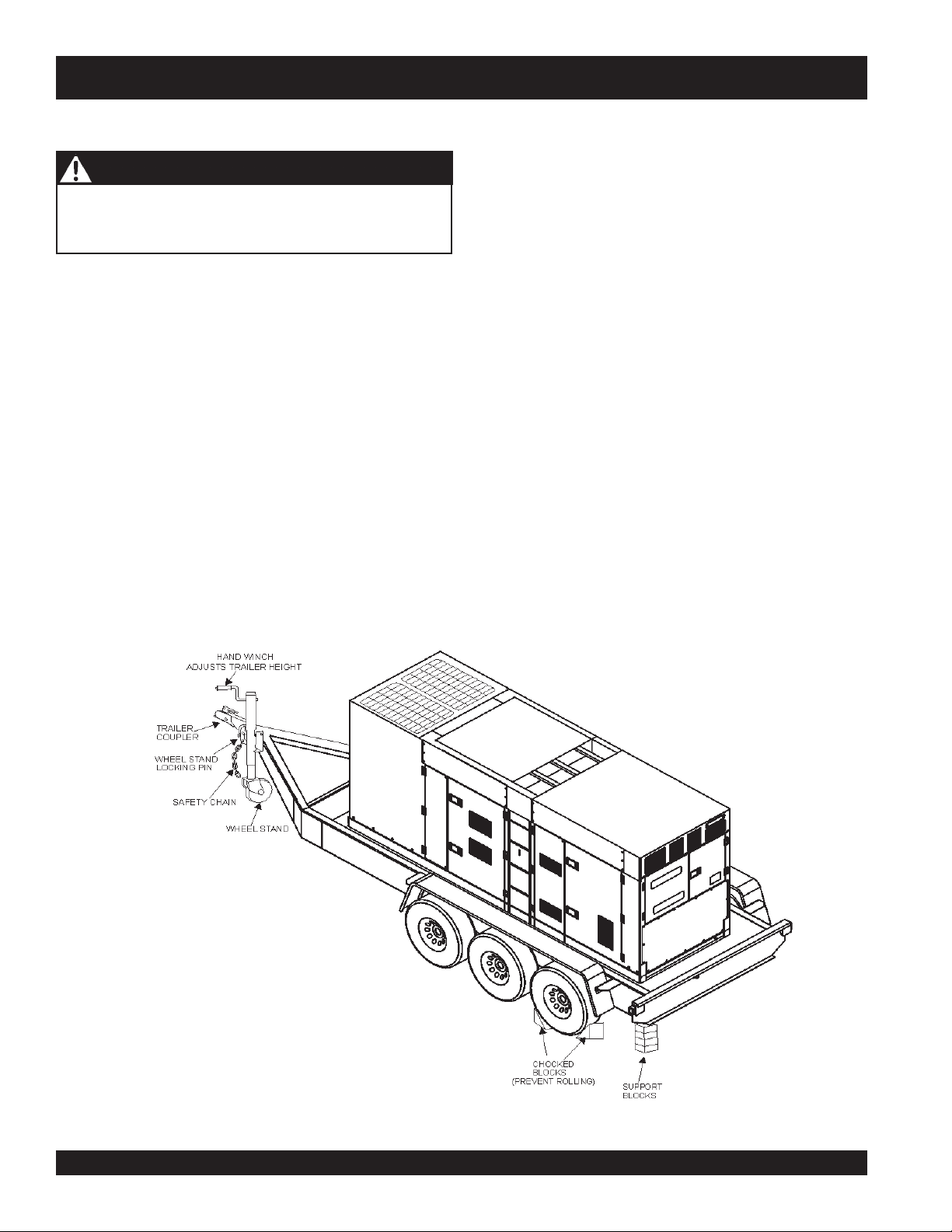
Towing Safety Precautions
■
ALWAYS attach trailer's safety chain to bumper of towing
vehicle.
CAUTION - TOWING REGULATIONS
Check with your county or state safety towing regulations
before towing your generator.
To reduce the possibility of an accident while transporting
the generator on public roads, always make sure the trailer
(Figure 4) that supports the generator and the towing vehicle
are in good operating condition and both units are
mechanically sound.
The following list of suggestions should be used when towing
your generator:
■
Make sure the hitch and coupling of the towing vehicle are
rated equal to, or greater than the trailer "gross vehicle weight
rating" (GVWR).
■
ALWAYS inspect the hitch and coupling for wear. NEVER
tow a trailer with defective hitches, couplings, chains etc.
■
Check the tire air pressure on both the towing vehicle and
the trailer. Also check the tire tread wear on both vehicles.
■
ALWAYS make sure the trailer is equipped with a "Safety
Chain".
■
ALWAYS make sure the vehicle and trailer directional,
backup, brake, and trailer lights are connected and working
properly.
■
Remember the maximum speed unless otherwise posted for
highway towing is 45 MPH. Recommended off-road towing
is not to exceed 10 MPH or less depending on type of terrain.
■
Place
while parked.
■
Place
prevent
■
Use the trailer's hand winch to adjust the height of the trailer,
then insert locking pin to lock wheel stand in place, while
parked.
■
Avoid sudden stops and starts. This can cause skidding, or
jackknifing. Smooth, gradual starts and stops will improve
gas milage.
■
Avoid sharp turns to prevent rolling.
■
Remove wheel stand when transporting.
■
DO NOT transport generator with fuel in tank.
chocked blocks
support blocks
tipping
underneath wheel to prevent
underneath the trailer's bumper to
, while parked.
rolling,
Figure 4. Generator and Trailer
PAGE 18 — DCA-800SSK (STD) — OPERATION AND PARTS MANUAL — REV. #4 (06/03/10)
Page 19

DCA-800SSK — TRAILER-SAFETY GUIDELINES
CAUTION - TRAILER INSPECTION
ALWAYS make sure the trailer is in good operating con-
dition. Check the tires for proper inflation and wear. Also
check the wheel lug nuts for proper tightness.
Explanation of Chart:
This section is intended to provide the user with trailer service and maintenance information. The service and maintenance guidelines referenced in this section apply a wide range
of trailers. Remember periodic inspection of the trailer will
ensure safe towing of the equipment and will prevent damage to the equipment and personal injury.
It is the purpose of this section to cover the major maintenance components of the trailer. The following trailer components will be discussed in this section:
Brakes
Tires
Lug Nut Torquing
Suspension
Electrical
Brake Troubleshooting Tables
Use the following definitions when reading Table 3.
1. Fuel Cell - Provides an adequate amount of fuel for the
equipment in use. Fuel cells must be empty when transporting equipment.
2. Braking System - System employed in stopping the
trailer. Typical braking systems are electric, surge, hydraulic, hydraulic-surge and air.
3. GVWR- Gross Vehicle Weight Rating (GVWR), is the
maximum number of pounds the trailer can carry, including the fuel cell (empty).
5. Frame Width - Measurement is from fender to fender
6. Jack Stand - Trailer support device with maximum pound
requirement from the tongue of the trailer.
7. Coupler - Type of hitch used on the trailer for towing.
8. Tire Size - Indicates the diameter of the tire in inches
(10,12,14, etc.), and the width in millimeters
(175,185,205, etc.). The tire diameter must match the
diameter of the tire rim.
9. Tire Ply - The tire ply (layers) number is rated in letters;
2-ply,4-ply,6-ply, etc.
10. Wheel Hub - The wheel hub is connected to the trailer’s
axle.
11. Tire Rim - Tires mounted on a tire rim. The tire rim must
match the size of the tire.
12. Lug Nuts - Used to secure the wheel to the wheel hub.
Always use a torque wrench to tighten down the lug
nuts. See Table 17 and Figure 67 for lug nut tightening
and sequence.
13. Axle - Indicates the maximum weight the axle can support in pounds, and the diameter of the axle expressed
in inches. Please note that some trailers have a double
axle. This will be shown as 2-6000 lbs., meaning two
axles with a total weight capacity of 6000 pounds.
14. Suspension - Protects the trailer chassis from shocks
transmitted through the wheels. Types of suspension
used are leaf, Q-flex, and air ride.
15. Electrical - Electrical connectors (looms) are provided
with the trailer so the brake lights and turn signals can
be connected to the towing vehicle.
16. Application - Indicates which units can be employed
on a particular trailer.
4. Frame Length - Measurement is from the ball hitch to
the rear bumper (reflector).
DCA-800SSK (STD) — OPERATION AND PARTS MANUAL — REV. #4 (06/03/10) — PAGE 19
Page 20

DCA-800SSK — TRAILER-SPECIFICATIONS
snoitacificepSreliarT.3elbaT
LEDOM NOITACILPPA LLECLEUF METSYSEKARB RWVG EMARF
W01-RLRT
01-RLRT
FX01-RLRT
W522-RLRT
004WLB-RLRT
X05-RLRT
FX
05-RLRT
W07-RLRT
X07-RLRT
FX07-RLRT
FX001-RLRT
521/58-RLRT
FX051-R
LRT
FX022-RLRT
FX003-RLRT
FX004-RLRT
FX006-RLRT
XS008-RLRT
,522WDS
003WLT,052WGS
-ACD,21GLT,01ACD
51
,21-GLT,01ACD
003-WLT,51ACD
,SREDLEW
SS0007AD
004-WLBONCIRTCELE
52-ACDONON.SBL007,2
52-ACDsnollaG14
07,06-,54-ACDONEGRUS.SBL000,7
07,06-,54-ACDTPOEGRUS.SBL000,7
07,06-,54-ACDsnollaG35
521,001-ACDsnollaG051
521,001,58-ACDsnollaG541
081,051-ACDsnollaG002
022-ACDsnollaG052
003-ACDsnollaG052
004-ACDsnollaG053
008,006-ACDsnollaG055
008,006-ACDsnollaG055
ONON.SBL009,1
ONON.SBL009,1
snollaG25
sretiL791
ONON.SBL002,2
sretiL551
sretiL102
sretiL865
sretiL945
sretiL757
sretiL649
sretiL649
sretiL423,1
sretiL280,2
sretiL280,2
ON.SBL009,1
ON.SBL007,2
EGRUSSBL000,7
EGRUSCILUARDYH.SBL000,7
CILUARDYH.SBL000,01
EGRUSCILUARDYH.SBL061,11
EGRUSCILUARDYH.SBL000,41
H.SBL000,81
EGRUSCILUARDY
CIRTCELE.SBL000,81
RIA.SBL000,03
RIA.SBL000,03
71,3
EMARF
HTGNEL
.gK268
.gK268
.gK268
.gK899
.SBL007,2
.gK422,1
.gK422,1
.gK422,1
.gK571,3
.gK571,3
.gK571,3
.gK5
.gK635,4
.gK260,5
.gK571,3
.gK561,8
.gK561,8
.gK706,31
.gK706,31
sehcni69
sretem34.2
sehcni69
sretem34.2
sehcni69
sretem34.2
sehcni58
sretem
34.2
AM/W
.ni451TS
sretem91.3
.ni421O/W
sretem41.3
sehcni421
sretem41.3
sehcni421
sretem41.3
sehcni681
sretem27.4
sehcni831
sretem05.3
sehcni831
sretem05.3
sehcni091
sretem28.4
sehcni681
sretem27.4
sehcni402
sretem81.5
sehcni222
s
retem36.3
sehcni832
sretem40.6
sehcni832
sretem40.6
sehcni483
sretem57.9
sehcni483
sr
etem57.9
HTDIW
sehcni05
sretem72.1
sehcni05
sretem72.1
s
ehcni05
sretem72.1
sehcni24
sretem60.1
sehcni55
sretem04.1
)LLATsehcni87(
sretem89.1
sehcni55
sretem04.1
sehcni55
sretem04.1
sehcni77
sretem59.1
sehcni66
sretem76.1
sehcni66
sretem76.1
sehcni67
sretem39.1
sehcni77
sretem59.1
sehcni48
sretem31.2
sehcni38
sretem01.2
sehcni38
sretem01.2
sehcni38
sretem01.2
sehcni69
sretem34
.2
sehcni69
sretem34.2
KCAJ
DNATS
).gK363(.SBL008
TLITLLUF
LEEHW
).gK363(.SBL008
LEEHWTLITLLUF
).gK363(.SBL008
LEEHWTLITLLUF
).gK363(.SBL008
LEEHWTLITLLUF
).gK363(.SBL008
UF
BL000,2
LEEHWTLITLL
).gK363(.SBL008
LEEHWTLITLLUF
).gK363(.SBL008
L
EEHWTLITLLUF
).gK709(.S
DAPTALF
).gK709
(.SBL000,2
DAPTALF
).gK709(.SBL000,2
DAPTALF
).gK709(.SBL000,2
DAPTALF
).gK709(.SBL000,2
DAPTALF
)
.gK862,2(.SBL000,5
DAPTALF
).gK862,2(.SBL000,5
DAPTALF
).gK862,2(.SBL000,5
DAPTALF
).gK862,2(.SBL000,5
DAP
TALF
).gK862,2(.SBL000,5
DAPTALF
).gK862,2(.SBL000,5
DAPTALF
PAGE 20 — DCA-800SSK (STD) — OPERATION AND PARTS MANUAL — REV. #4 (06/03/10)
Page 21

DCA-800SSK — TRAILER-SPECIFICATIONS
)t'noC(snoitacificepS.3elbaT
LEDOM RELPUOC SERIT SLEEHW ELXA SBUH NOISNEPSUS LACIRTCELE
W01-RLRT
01-RLRT
FX01-RLRT
W522-RLRT
004WLB-RLRT
X05-RLRT
FX05-RLRT
W07-RLRT
X07-RLRT
FX07-RLRT
FX001-RLRT
521/58-RLRT
FX0
51-RLRT
FX022-RLRT
FX003-RLRT
FX004-RLRT
FX006-R
LRT
RA008-RLRT
2
SSALCLLAB"2
ELBATSUJDA2
SSALCLLAB"2
ELBAT
SUJDA2
SSALCLLAB"2
ELBATSUJDA2
SSALCLLAB"2
ELBATSUJDA2
SSALCLLAB"2
ELBAT
SUJDA2
SSALCLLAB"2CRL31-87B"05.4X"31.sbl005,3
SSALCLLAB"2CRL31-87B"05.4X"31.sbl005,3
SSALCLLAB"
ELBATSUJDA"3
SSALCLLAB"2
ELBATSUJDA"3
SSALCLLAB"2
ELBATSUJDA"3
TPO6/5-2ELBATSUJDA
EYE"3
TPO6/5-2ELBATSUJDA
EYE"3
EYELLAB"3E61-057
ELBATSUJDAEYE"3E61R58/532TS
ELBATSUJDAEYE"3E61R58/532TS
ELBATSUJDAEYE"3E61R58/532TS
LEEHWHT5H5.71R57/512TS
LEEHWHT5H5.71R57/512TS
C31-571"05.4X"312X2#0022GUL5FAEL3/WMOOLERIW4
C31-571"5.4X"312X2#0022GUL5FAEL3TALFELOP4
C31-571"5.4X"312X2#0022GUL5FAEL3T
B31-571"5.4X312X2#0022GUL5XELFQTALFELOP4
C31-571"5.4X312X2#0022GUL5FAEL3TALFELOP4
"8/3-2
"8/3-2
C41-502
)4(SAIB
C41-5
02
)4(SAIB
C41-502
)4(SAIB
C51-502
)4(SAIB
D51R57/522TS
)4(LAIDAR
)4(SAIB
)4(
LAIDAR
)6(LAIDAR
)6(LAIDAR
)8(LAIDAR
)8(
LAIDAR
"5X"41.sbl005,3
"5X"41.sbl005,3
"5X"41.sb
"5.5X"41.sbl005,3
"6x"41.sbl000,6-)2(GUL6FAEL7MOOLERIW4
"7X"61.sbl000,6-)2(GUL8FAEL7MOOLERIW4
"7X"61.sbl000,7-)2(GUL8XELFQMOOLERIW4
"7X"61.sbl000,6-)2
"7X"61.sbl000,7-)3(GUL8XELFQMOOLERIW4
"7X"61.sbl000,01-)3(GUL8FAEL7MOOLERIW6
"7X"61.sbl000,01-)3(GUL8EDIR-RIAMOOLERIW6
"3
"3
l005,3
"3
"3
(GUL8XELFQMOOLERIW4
GUL5FAEL4TALF
GUL5FAEL4TALFREBBURELOP4
GUL5FAEL5TALFREBBURELOP4
GUL5FAEL5TALFREBBURELOP4
GUL5FAEL5TALFREBBURELOP4
GUL5FAE
L5MOOLERIW4
TALFELOP4
ALFELOP4
REBBURELOP4
DCA-800SSK (STD) — OPERATION AND PARTS MANUAL — REV. #4 (06/03/10) — PAGE 21
Page 22
DCA-800SSK — OPERATION AND SAFETY DECALS
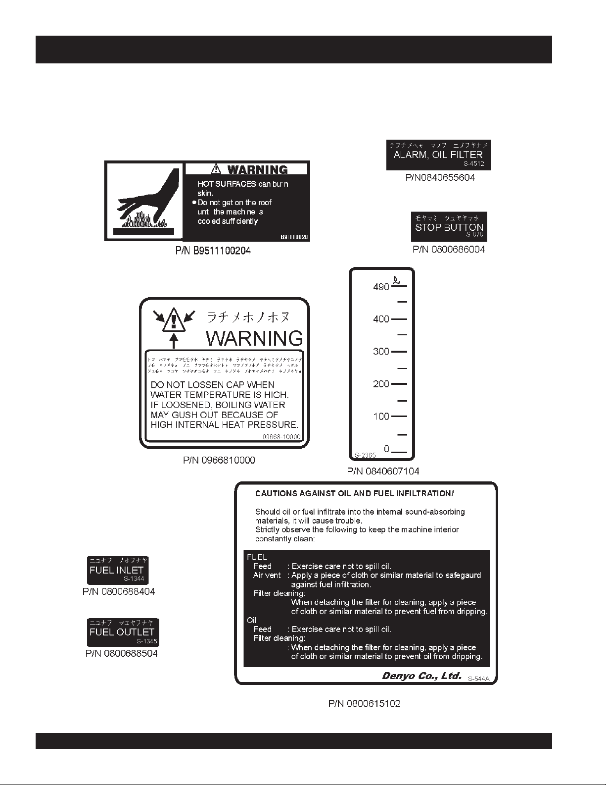
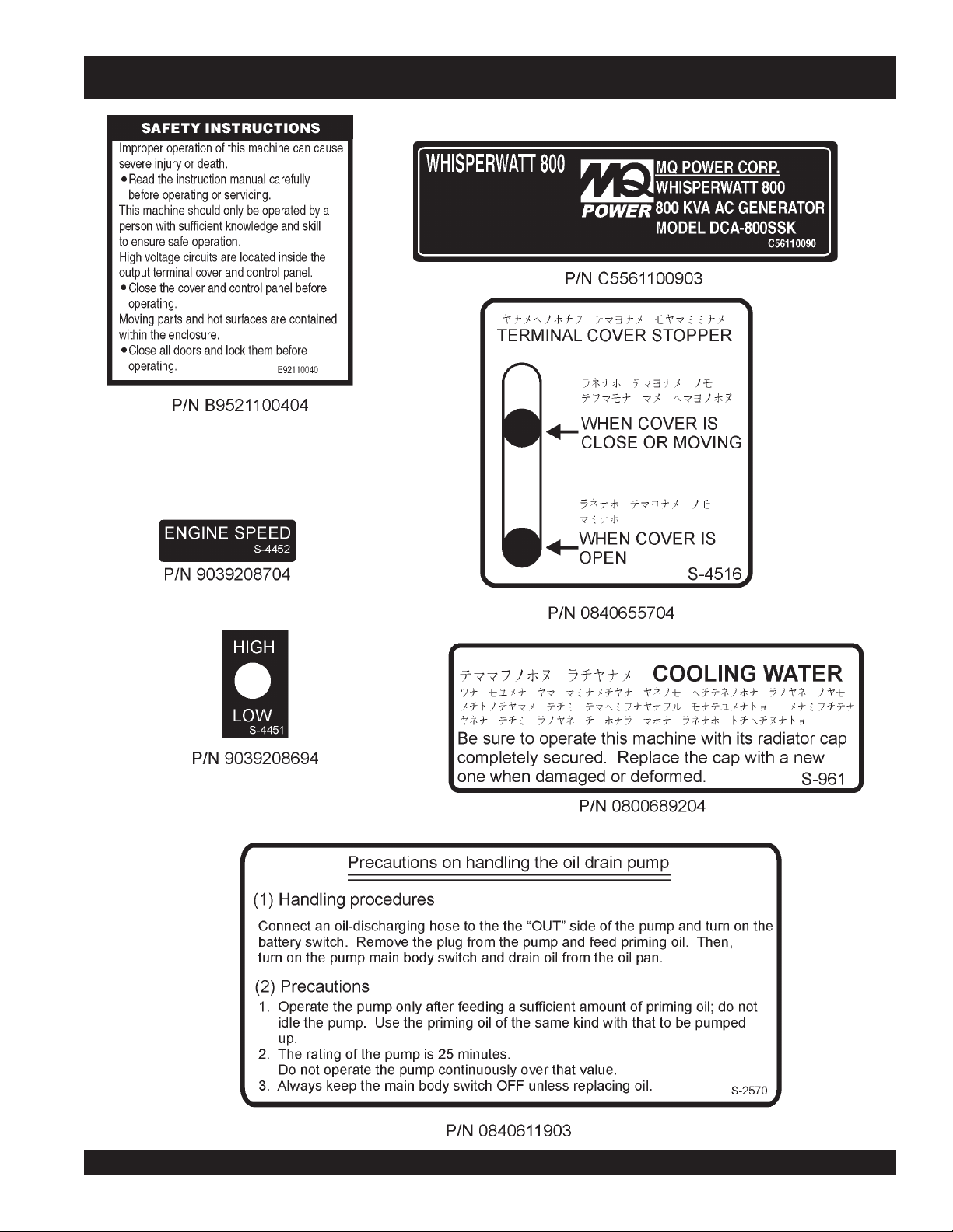
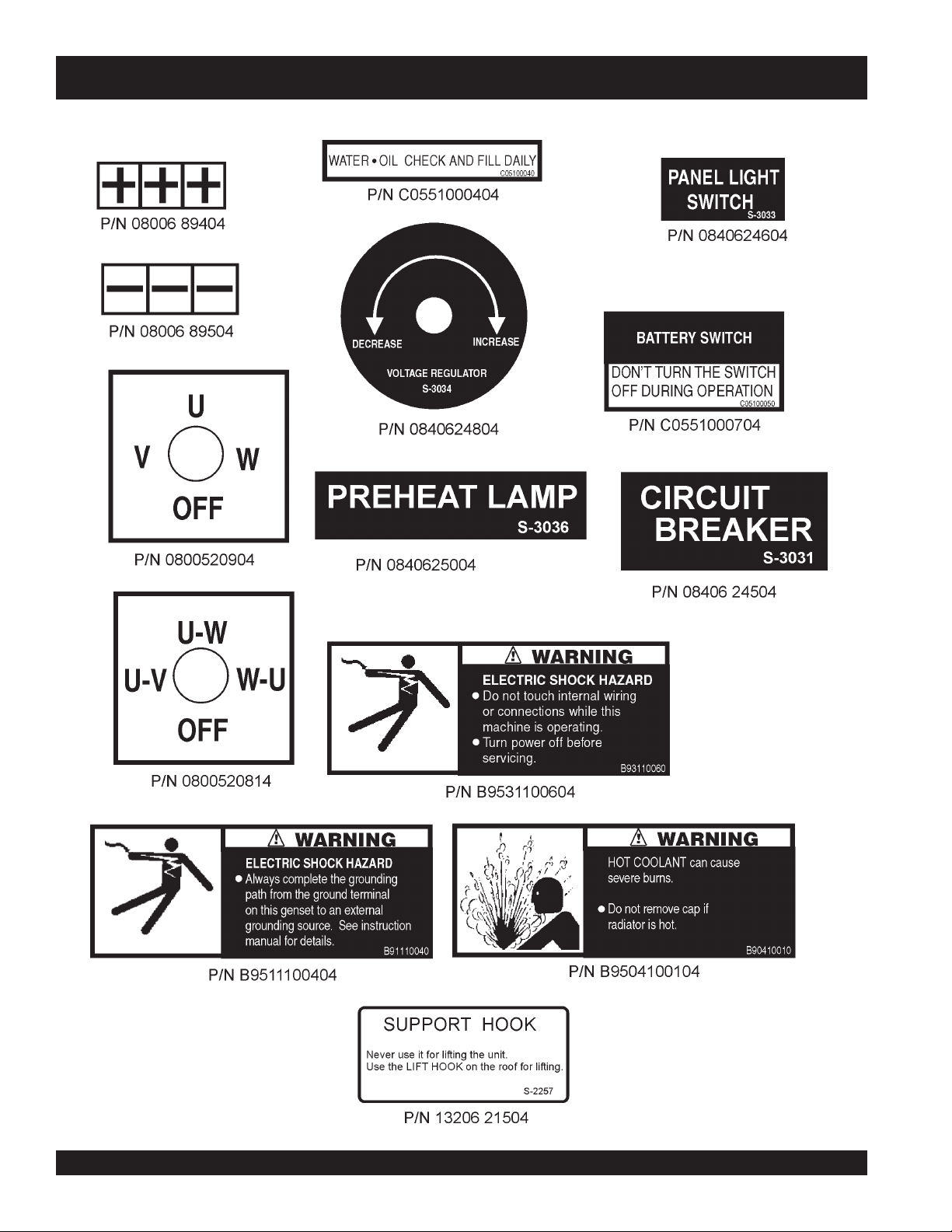
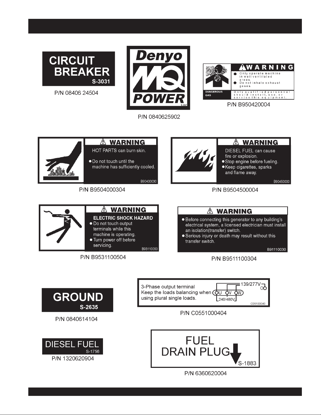
Machine Safety Decals
The DCA-800SSK generator is equipped with a number of safety decals. These decals are provided for operator safety and
maintenance information. The illustrations below and on the preceding pages shows the decals as they appear on the machine.
Should any of these decals become unreadable, replacements can be obtained from your dealer.
PAGE 22 — DCA-800SSK (STD) — OPERATION AND PARTS MANUAL — REV. #4 (06/03/10)
Page 23
DCA-800SSK — OPERATION AND SAFETY DECALS
DCA-800SSK (STD) — OPERATION AND PARTS MANUAL — REV. #4 (06/03/10) — PAGE 23
Page 24
DCA-800SSK — OPERATION AND SAFETY DECALS
PAGE 24 — DCA-800SSK (STD) — OPERATION AND PARTS MANUAL — REV. #4 (06/03/10)
Page 25
DCA-800SSK — OPERATION AND SAFETY DECALS
DCA-800SSK (STD) — OPERATION AND PARTS MANUAL — REV. #4 (06/03/10) — PAGE 25
Page 26

DCA-800SSK — GENERAL INFORMATION
DCA-600SSK FAMILIARIZATION
Generator
The MQ Power Model DCA-800SSK is a 640 kW
that has been designed as a high quality portable (requires
a trailer for transport) power source for telecom sites, lighting
facilities, power tools, submersible pumps and other
industrial and construction machinery.
Engine Control Panel
The “Engine Control Panel” is provided with the following:
Tachometer
Water Temperature Gauge
Oil Pressure Gauge
Oil Filter Alarm Lamp
Charging Ammeter Gauge
Engine Warning Lamp Module
Air Cleaner Indicator
Engine Speed Switch
Pre-Heat Button
Pre-Heat Lamp
Emergency Stop Button
Battery Switch
Generator Control Panel
The “Generator Control Panel” is provided with the following:
Output Voltage Adjustment Knob
Frequency Meter (Hz)
AC Ammeter (Amps)
AC Voltmeter (Volts)
Ammeter Change-Over Switch
Voltmeter Change-Over Switch
Panel Light
Panel Light Switch
MPEC Module
Circuit Breaker ON/OFF Lamps
Circuit Breaker ON Switch
Circuit Breaker Reset Switch
Pilot Lamp
generator
Open Delta Excitation System
The DCA-800SSK generator is equipped with the state of
the art "
system consist of an electrically independent winding wound
among stationary windings of the AC output section.
There are four connections of the open delta A, B, C, and D.
During steady state loads, the power from the voltage
regulator is supplied from the parallel connections of A to B,
A to D, and C to D. These three phases of the voltage input
to the voltage regulator are then rectified and are the
excitation current for the exciter section.
When a heavy load, such as a motor starting or a short
circuit occurs, the automatic voltage regulator (AVR)
switches the configuration of the open delta to the series
connection of B to C. This has the effect of adding the
voltages of each phase to provide higher excitation to the
exciter section and thus better voltage response during the
application of heavy loads.
The connections of the AVR to the AC output windings are
for sensing only. No power is required from these windings.
The open-delta design provides virtually unlimited excitation
current, offering maximum motor starting capabilities. The
excitation does not have a "
according the demands of the required load up to the
horsepower of the engine.
Engine
The DCA-800SSK is powered by a 6 cylinder, water cooled,
turbocharged KOMATSU Model SA12V140 diesel
This engine is designed to meet every performance
requirement for the generator. Reference Table 2 for engine
specifications.
In keeping with Multiquip's policy of constantly improving
its products, the specifications quoted herein are subject to
change without prior notice.
The basic controls and indicators for the DCA-800SSK
generator are addressed on the following pages.
Open-Delta
" excitation system. The open delta
fixed ceiling
" and responds
engine.
Microprocessor Controlled Alarm System
The DCA-800SSK generator is equipped with various alarms
and LED status indicators. These alarms and status
indicators are provided to add safety to the generator when
operating under normal conditions. The DCA-800SSK
generator is designed to shutdown in the event of low oil,
high coolant temperature, low battery and other operation
conditions that may cause severe damage to the generator.
PAGE 26 — DCA-800SSK (STD) — OPERATION AND PARTS MANUAL — REV. #4 (06/03/10)
Electronic Governor System
The electronic governor system is made up of two parts, an
electronic controller that monitors frequency variation as the
load increases and decreases, and an electronic actuator
that controls the engine throttle. The frequency is regulated
at ±0.25 to help protect sensitive equipment.
Page 27
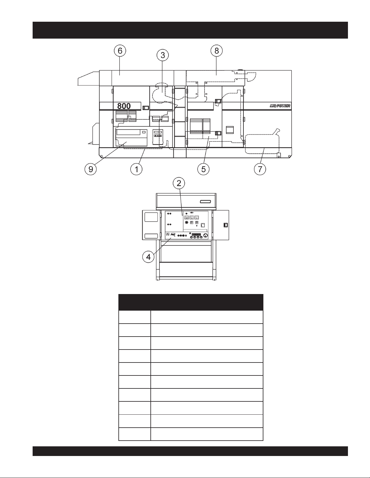
DCA-800SSK — MAJOR COMPONENTS
DCA-600SSK — MAJOR COMPONENTS
4elbaT
.
.ONMETINOITPIRCSED
1ylbmessArotareneG
2ylbmessAlenaPlortnoCrotareneG
3ylbmessArotaidaRdnaenignE
4ylbmessAlenaP
5ylbmessAyrettaB
6ylbmessAerusolcnE
7ylbmessAknaTleuF
8ylbmessArelffuM
9ylbmessAlanimreTtuptuO
DCA-800SSK (STD) — OPERATION AND PARTS MANUAL — REV. #4 (06/03/10) — PAGE 27
gnitarepOenignE
stnenopmoCrojaMrotareneG
Page 28
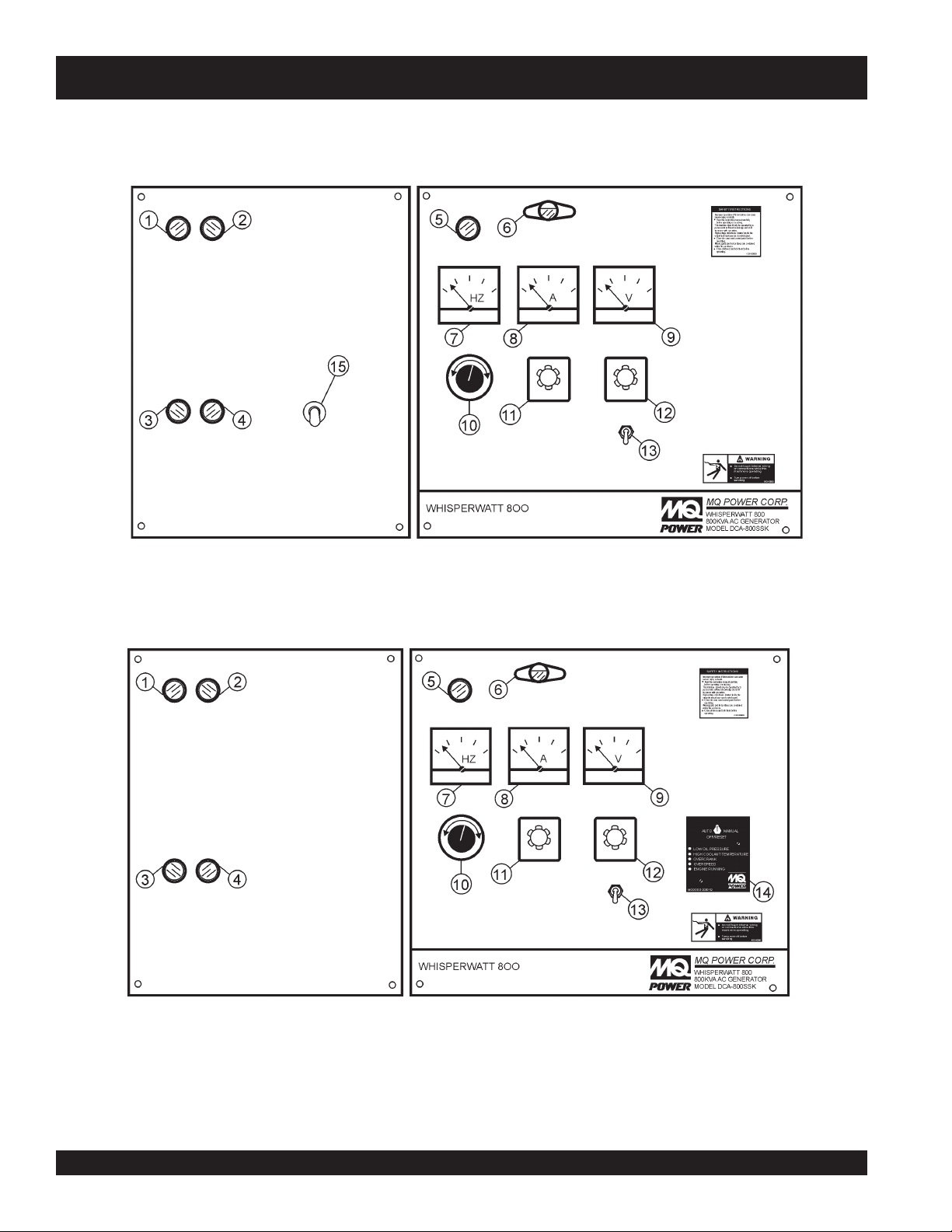
DCA-800SSK — GENERATOR CONTROL PANEL
Up to S/N 3699247
S/N 3699248~
Figure 6. Generator Control Panel
PAGE 28 — DCA-800SSK (STD) — OPERATION AND PARTS MANUAL — REV. #4 (06/03/10)
Page 29

DCA-800SSK — GENERATOR CONTROL PANEL
The definitions below describe the controls and functions of the
DCA-800SSK "
1. Circuit Breaker OFF lamp - This indicates the main circuit
breaker is "OFF" and the generator is unable to supply
power to the load.
2. Circuit Breaker ON lamp - This indicates the main circuit
breaker is in "ON" and the generator is able to supply power
to the load.
3. Circuit Breaker Reset Switch - This button will turn off
the circuit breaker.
4. Circuit Breaker Switch - This button will turn on the main
circuit breaker.
5. Pilot Lamp – Indicates that the generator is working
properly.
6. Panel Light – Normally used in dark areas or at night time.
When activated, panel lights will illuminate. When lit this
light will make it easier to read the meters and gauges.
When the generator is not in use be sure to turn the panel
light switch to the OFF position.
7. Frequency Meter - Indicates the output frequency in hertz
(Hz). Typical reading is 60Hz.
8. AC Ammeter - Indicates the amount of current the load is
drawing from the generator.
9. AC Voltmeter - Indicates the single phase output voltage
present at the UVW terminals.
10. Voltage Regulator Control – Allows manual adjustment
of the generator’s output voltage.
11. Ammeter Change-Over Switch - This switch allows the
AC ammeter to indicate the current flow into the load
connected to any phase of the output terminals or to be
switched off.
12. Voltmeter Change-Over Switch - This switch allows the
AC voltmeter to indicate phase to phase voltage between
any two phases of the output terminals or to be switched
off.
13. Panel Light Switch - When activated will turn on control
panel light.
14. Engine Controller - This unit
(S/N 3699248~) contains a
vertical row of status LED's
(inset), that when lit, indicates
an engine malfunction (fault)
has been detected. When a
fault has been detected by
the Engine Controller as a
major fault, it will shut down
the generator.
Control Panels
" (Figure 9).
During
crank the engine for 10 seconds before disengaging.
If the engine does not engage (start) by the third attempt, the
engine will be shutdown by the engine controller's " Over Crank
Protection" mode. If the engine engages at a speed (RPM's) that
is not safe, the controller will shutdown the engine by initializing
the "Over Speed Protection" mode.
Also the engine controller will shutdown the generator in the
event of low oil pressure, high coolant temperature, low coolant
level, and loss of magnetic pickup. These conditions can be
observed by monitoring the LED status indicators on the front of
the engine controller module.
A. Off/ Manual/ Auto Switch – This switch controls the running
B. Low Oil Pressure – Indicates the engine pressure has
C. High Coolant Temperature – Indicates the engine
D. Overcrank Shutdown – Indicates the unit has attempted
E. Overspeed Shutdown – Indicates that the engine is
F. Engine Running – Indicates that engine is running at a
15. Throttle Lever (Up to S/N 3699247) - This handle
cranking cycle
of the generator. If this switch is left in the "OFF" position,
the generator will not run. When this switch is set to the
manual
If the generator is to be connected to a building's AC power
source via a transfer switch (isolation), place the switch in
the
the AC line output from the building's power source.
fallen below 15 psi. The oil pressure is detected using
variable resistive values from the oil pressure sending unit.
This is considered a
temperature has exceeded 215
is detected using variable resistive values from the
temperature sending unit. This is considered a
to be started a pre- programmed number of times, and has
failed to start. The number of cycles and duration are
programmable. Typical programmable start settings is 3
cycles with a 10 second duration .This is considered a
major
running at an unsafe speed. This is considered a
fault.
safe operating speed.
controls the speed of the engine (low or high).
, The engine controller will attempt to
position, the generator will start immediately.
auto
position. In this position the generator will monitor
major
fault.
°
F. The engine temperature
major
fault.
fault.
major
DCA-800SSK (STD) — OPERATION AND PARTS MANUAL — REV. #4 (06/03/10) — PAGE 29
Page 30
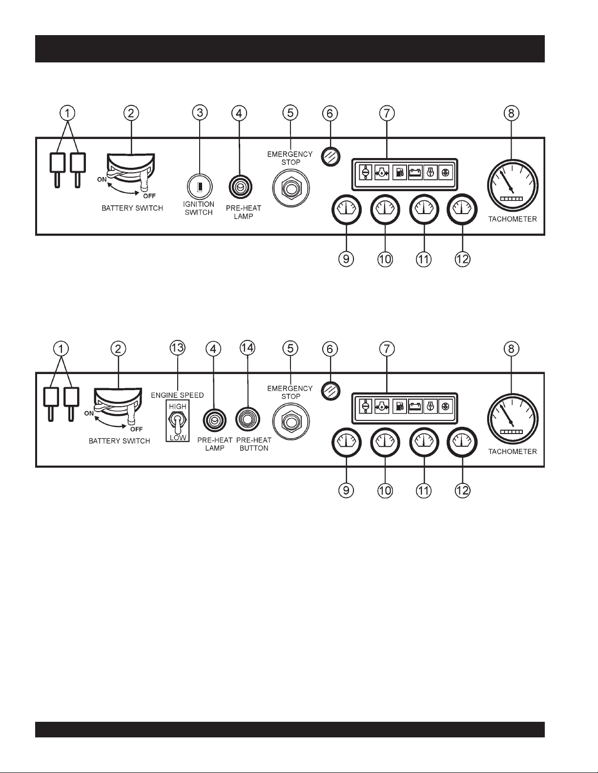
DCA-800SSK — ENGINE OPERATING PANEL
Up to S/N 3699247
S/N 3699248~
Figure 7. Engine Operating Panels
PAGE 30 — DCA-800SSK (STD) — OPERATION AND PARTS MANUAL — REV. #4 (06/03/10)
Page 31

DCA-800SSK — ENGINE OPERATING PANEL
The definitions below describe the controls and functions of the
DCA-800SSK "
Engine Operating Panels
" (Figure 11).
1. Air Cleaner Indicators – When lit, indicates air cleaner
must be serviced or replaced. This engine of this generator
requires two air cleaners.
2. Battery Switch – This switch should be set to the "ON"
position during normal operation. When the engine has
been stopped, place this switch in the "OFF" position. DO
NOT turn this switch during normal operation; it will cause
damage to the electrical equipment.
3. Ignition Switch (Up to S/N 3699247) – Four position
switch,
key to start and stop engine.
pre-heat, stop, run
and
.
start
. Insert ignition
4. Preheat Lamp – Indicates that the glow plugs of the
diesel engine are hot is ready to start.
5. Emergency Stop Button – Press this button to stop the
engine in the event of an emergency. DO NOT use this
button as a normal means of stopping the engine.
6. Oil Filter Alarm Lamp – Indicates the oil filter is clogged
and needs replacement.
7. Engine Warning Display (LED) Module – This module
display’s the following engine failures:
A. Overheat Lamp - This lamp turns on when
the cooling water temperature rises beyond
normal level. If the this light is on, the
emergency shutdown device will stop the
E. Clogged Air Filter Lamp - This indicates
the air filter is clogged. Stop the engine
and replace the air filter.
8. Tachometer - Indicates engine speed in RPMs for 60Hz
operation. Normal operation is 1800 RPMs when the load
is applied. A built in hour meter will record the number of
operational hours that the generator has been in use.
8. Oil Pressure gauge - This gauge indicates the oil
pressure. During normal operation, the gauge should read
in the 'green' zone. When starting the generator, the oil
pressure may read slightly higher, but after the engine
warms up, it should return to the "
9. Water Temp Gauge - This indicates the temperature of the
coolant. During normal operation this gauge should read
in the 'green' zone.
11. Charging Ammeter Gauge - This gauge indicates the
current supplied by the alternator, which supplies current
from the generator's control circuits and battery charging
system.
12. Fuel Level Gauge - This gauge indicates diesel fuel level.
13. Engine Speed Switch
changes the engine speed from
14. Preheat Button – Press and hold this button for
30seconds until the preheat lamp is lit (ON).
engine.
green
" zone.
(S/N 3699248~) – This switch
low
(idle) to
high
.
B. Low Oil Pressure Lamp - This lamp will
turn on if the Auto-OFF/Reset-Manual
switch on the Engine Controller is set in
"Manual" position. It will remain lit until the
oil pressure is at a normal level. If the lamp
turns on at any time during the normal
working time of the generator, it will shut
down the engine.
C. Low Fuel Level Lamp - When lit, this
indicates to add fuel. Let the engine cool
before adding diesel fuel.
D. Low Battery Fluid Lamp - This indicates
the battery fluid level is low. This
indicator will shut down the engine. Refill
the battery with distilled water.
DCA-800SSK (STD) — OPERATION AND PARTS MANUAL — REV. #4 (06/03/10) — PAGE 31
Page 32

DCA-800SSK — OUTPUT TERMINAL OVERVIEW
Output Terminal Familiarization
The “
Output Terminal Panel
the following:
Three 240/139V output receptacles, 50 amp
Three AUX. circuit breakers 240V @50 amps
Two 120V GFCI receptacles, 20 amp
Two (2) GFCI circuit breakers 120V@ 20 amps
Eight (16) output terminal lugs
Figure 8. Output Terminal Panel
” (Figure 8) is provided with
Output Terminal Panel
Shown below (Figure 8) is the
up on the cover to gain access to receptacles and terminal
lugs.
NOTE
Output Terminal Panel
Terminal legs "O" and "Ground"
are considered
bonded grounds
, lift
.
PAGE 32 — DCA-800SSK (STD) — OPERATION AND PARTS MANUAL — REV. #4 (06/03/10)
Page 33

DCA-800SSK — OUTPUT TERMINAL PANEL OVERVIEW
120 VAC GFCI Receptacles
There are two 120 VAC, 20 amp GFCI (Duplex Nema 5-20R)
recepacles provided on the output terminal panel. These
receptacles can be accessed in any
board
position. Each receptacle is protected by a 20 amp
circuit breaker. These breakers are located directly above
the GFCI receptacles. Remember the load output (current)
of both GFCI receptacles is dependent on the load
requirements of the UVWO terminals.
Pressing the
being tripped. Pressing the "
the center of the receptacle will check the GFCI function.
Both receptacles should be tested at least once a month.
reset
button resets the GFCI receptacle after
Test Button
voltage change-over
" (See Figure 9) in
Each auxiliary receptacle is protected by a 50 amp circuit
breaker. These breakers are located directly above the GFCI
receptacles. Remember the load output (current) on all three
receptacles is dependent on the load requirements of the
UVWO terminals.
Turn the
control panel to obtain the desired voltage. Turning the knob
clockwise will
clockwise will
Figure 11. Voltage Regulator Control Knob
Removing the Plastic Face Plate (UVWO Terminals)
The UVWO terminal lugs are protected by a plastic face
plate cover (Figure 12). Un-lock the locking latch, and lift
the terminal cover to gain access to the plastic face plate.
Remove the screws securing the face plate to the terminal
enclosure, then lift the plastic hinged face plate.
voltage regulator control knob
increase
decrease
the voltage, turning the knob counter-
the voltage.
(Figure 11) on the
After the load wires have been securely attached to the
UVWO terminals, reinstall the plastic face plate. Place the
Figure 9. G.F.C.I. Receptacle
Twist Lock Dual Voltage 240/139 VAC Receptacles
There are three 240/139 VAC, 50 amp auxiliary twist-lock
(CS-6369) receptacles (Figure 10) provided on the output
terminal panel. These receptacles can be accessed in any
voltage change-over board
position.
terminal cover in the down position and secure the locking
latch.
Figure 12. Plastic Face Plate (UVWO Terminals)
Figure 10. 240/139 VAC Twist-Lock
Auxiliary Receptacles
DCA-800SSK (STD) — OPERATION AND PARTS MANUAL — REV. #4 (06/03/10) — PAGE 33
Page 34

DCA-800SSK — OUTPUT TERMINAL PANEL OVERVIEW
Connecting Loads
Loads can be connected to the generator by the UVWO terminal
lugs or the convenience receptacles. (See Figure 13). Make
sure to read the operation manual before attempting to connect
a load to the generator.
To protect the UVWO output terminals from overload, a 3pole, 1,600 amp,
sure to switch
prior to starting the engine.
main
circuit breaker is provided. Make
ALL
circuit breakers to the "OFF" position
Over Current Relay
An
over current relay
circuit breaker. In the event of an overload, both the circuit
breaker and the over current relay may trip. If the circuit
breaker can not be reset, the
rent relay must be pressed. The over current relay is located in the control box.
(Figure 14) is connected to the main
reset button
Figure 14. Over Current Relay
on the over cur-
Figure 13. Connecting Loads
Maximum Power Output (KW)
The entire load connected to the UVWO output terminal lugs,
duplex and auxiliary receptacles must not exceed 704 kW in
standby or 640 kW in prime output.
PAGE 34 — DCA-800SSK (STD) — OPERATION AND PARTS MANUAL — REV. #4 (06/03/10)
Page 35

DCA-800SSK— LOAD APPLICATION
Single Phase Load
Always be sure to check the nameplate on the generator
and equipment to insure the wattage, amperage and
Three Phase Load
When calculating the power requirements for 3-phase power
use the following equation:
frequency requirements are satisfactorily supplied by the
generator for operating the equipment.
Generally, the wattage listed on the nameplate of the
equipment is its rated output. Equipment may require 130—
150% more wattage than the rating on the nameplate, as
the wattage is influenced by the efficiency, power factor and
NOTE
starting system of the equipment.
NOTE
If wattage is not given on the equipment's
name plate, approximate wattage may be
determined by multiplying nameplate
voltage by the nameplate amperage.
An inadequate size connecting cable which cannot carry
the required load can cause a voltage drop which can burn
out the appliance or tool and overheat the cable. See Table 5.
WATTS = VOLTAGE x AMPERAGE
The power factor of this generator is 0.8. See Table 5 below
when connecting loads.
daoLyBrotcaFrewoP.31elbaT
When connecting a resistance load such as an
incandescent lamp or electric heater, a capacity of up
to the generating set’s rated output (kW) can be used.
When connecting a fluorescent or mercury lamp, a
capacity of up to the generating set’s rated output (kW)
daoLfOepyTrotcaFrewoP
srotom
noitcudniesahp-elgniS
,sretaehcirtcelE
spmaltnecsednacni
57.0-4.0
0.1
multiplied by 0.6 can be used.
When connecting an electric drill or other power tools,
pay close attention to the required starting current
capacity.
Motors and motor-driven equipment
draw much greater current for
starting than during operation.
spmal
nitnerruC
serepmA
5.20
50060021.tf005.tf003.tf002.tf521
5.70090081.tf053.tf002.tf521.tf001
0100210042.tf052.tf051.tf00
5100810063.tf051.tf001.tf56
0200420084.tf521.tf57.tf05
:NOITUAC .egatlovwolmorftlusernacegamadtnempiuqE
altnecseroulF
,secivedcinortcelE
sttaWnIdaoLhtgneLelbaCelbawollAmumixaM
021tA
stloV
03006.tf0001.tf006.tf573.tf052
042tA
stloV
yrucem,spm
tnempiuqenoitacinummoc
eriW01#eriW21#eriW41#eriW61#
9.0-4.0
0.1
)noitarepOesahPelgniS,zH06(noitceleSelbaC.6elbaT
1
DCA-800SSK (STD) — OPERATION AND PARTS MANUAL — REV. #4 (06/03/10) — PAGE 35
When connecting ordinary power tools, a capacity of up to
the generating set’s rated output (kW) multiplied by 0.8 can
be used.
DANGER - ELECTRICAL SYSTEM HAZARDS
Before connecting this generator to any building’s electrical
system, a
(transfer) switch
licensed electrician
must install an
. Serious damage to the building’s
isolation
electrical system may occur without this transfer switch.
If 3Ø load (kVA) is not given on
the equipment nameplate,
NOTE
approximate 3Ø load output
maybe determined by multiplying
voltage by amperage by 1.732.
Page 36

DCA-800SSK — GENERATOR OUTPUTS
Generator Output Voltages
A wide range of voltages are available to supply voltage for
many different applications. Voltages are selected by applying jumpers (6) to the
voltage change-over board
(Figure 15).
Generator Amperage
Tables 8 and 9 describe the generator’s current output capability for both 1Ø-phase and 3Ø phase applications.
To obtain some of the voltages as listed in Table 7 (see
below) will require a fine adjustment using the
lator
(VR)
control knob
located on the control panel.
voltage regu-
Voltage Change-Over Board
voltage change-over board
The
(Figure 15) is located on
the control box, behind the generator control panel. This
board has been provided for ease of voltage selection.
Ø1—sgnitaRerepmArotareneG.8elbaT
WKV931V042V772V084
0480202140106
001915103162051
061138184714142
022241,1266375133
082454,1248037124
043567,1220,1688115
004770,2302,1240,11
064883,2383,1991,1296
025007,2465,1553,1287
085110,3447,1115,1278
046323,3529,1766,1269
06
Figure 15. Voltage Change-Over Board
240V Configuration
CAUTION - CHANGING JUMPER PLATES
NEVER attempt to place jumper plates on the
change-over board
There exists the possibility of
while the generator is in operation.
electrocution, electrical
voltage
shock or burn, which can cause severe bodily harm
or even death!
segatloVelbaliavArotareneG.7elbaT
V802V022V042V614V044V084
esahP-eerhT
V021V721V931V042V452V772
esahP-elgniS
Ø3—sgnitaRerepmArotareneG.9elbaT
WKV042V084
0402106
001103051
061184142
022266133
082248124
043220,1115
004302,1106
064383,1296
025465,1287
085447,1278
046529,1269
PAGE 36 — DCA-800SSK (STD) — OPERATION AND PARTS MANUAL — REV. #4 (06/03/10)
Page 37

DCA-800SSK — GENERATOR OUTPUTS/GAUGE READING
Maximum Amps
Table 10 shows the
vide. DO NOT exceed the maximum amps as listed.
maximum
:ledoMKSS006ACD
amps the generator can pro-
spmAmumixaM.9elbaT
detaR
egatloV
esahPelgniS
tloV021
esahPelgniS
tloV042
esahPeerhT
tloV042
esahPeerhT
tloV084
spmAmumixaM
)eriw4(spma8.7771
)eriw4(spma9.888
spma6.4291
spma3.269
Figure 17. AC Voltmeter
Change-Over Switch
How to Read the Output Terminal Gauge.
The AC ammeter and AC voltmeter change-over switches
on the control panel DO NOT effect the generator output.
They are provided to help observe how much power is being
supplied, produced at the UVWO terminals lugs.
When the voltage change-over board is jumpered for 3Ø,
240V operation (See Figure 16), place the
Change-Over Switch
the
AC Ammeter Change-Over Switch
(Figure 17) to the W-U position and
AC Voltmeter
(Figure 19) to the U
Figure 19. AC Ammeter
Change-Over Switch
or W position to read the output on the selected leg.
Figure 18 AC Voltmeter
Gauge
(Volt reading on W-U Lug)
40
20
0
60
75
A
Figure 20. AC Ammeter
(Amp reading on U lug)
The
NOTE
ammeter
gauges are only active when the
and
voltmeter
UVWO terminals are in use.
Figure 16. Voltage Change-Over Board
240V Configuration
DCA-800SSK (STD) — OPERATION AND PARTS MANUAL — REV. #4 (06/03/10) — PAGE 37
Page 38

DCA-800SSK — OUTPUT TERMINAL PANEL CONNECTIONS
UVWO Terminal Output Voltages
Various output voltages can be obtained using the UVWO
output terminal lugs. The voltages at the terminals are dependent on the placement of the jumpers plates (6) on the
Voltage Change-Over Board
Voltage Regulator Control Knob
Remember the voltage change-over board determines the
range
of the output voltage and can be configured in two
different positions that provide 6 different output voltages at
the UVWO output terminals. The generator is shipped from
the factory in the 240V configuration. The voltage regulator
(VR) allows the user to increase or decrease the selected
voltage.
3Ø-240V UVWO Terminal Output Voltages
1. Jumper the voltage change-over board for 240V operation
as shown in Figure 21.
and the adjustment of the
.
1Ø-240V UVWO Terminal Output Voltages
1. Make sure the voltage change-over board is jumpered
for 240V operation as shown in Figure 21 .
2. Connect the load wires to the UVWO terminals as shown
in Figure 24.
Figure 23. Voltage Regulator Knob
Figure 21. Voltage Change-Over Board
240V Configuration
2. Connect the load wires to the UVWO terminals as shown
in Figure 22.
1Ø-139V UVWO Terminal Output Voltages
1. Make sure the voltage change-over board is jumpered
for 240V operation as shown in Figure 21.
2. Connect the load wires to the UVWO terminals as shown
in Figure 25.
Figure 22. UVWO Terminal Lugs
3Ø-240V Connections
3. Turn the voltage regulator knob (Figure 23) clockwise to
increase voltage output, turn counterclockwise to
decrease voltage output. Use voltage regulator
adjustment knob whenever fine tuning of the output
voltage is required
Figure 24. UVWO Terminal Lugs
1Ø-240V Connections
Figure 25. UVWO Terminal Lugs
1Ø-139V Connections
PAGE 38 — DCA-800SSK (STD) — OPERATION AND PARTS MANUAL — REV. #4 (06/03/10)
Page 39

DCA-800SSK — OUTPUT TERMINAL PANEL CONNECTIONS
3Ø-480V UVWO Terminal Output Voltages
1. Jumper the voltage change-over board for 480V operation
as shown in Figure 26. This configuration uses 6 jumper
plates in 3 different positions. Remember there are 2
jumper plates at every position. Every jumper plate
must
1Ø-480V UVWO Terminal Output Voltages
1. Make sure the voltage change-over board is jumpered
for 480V operation as shown in Figure 26.
2. Connect the load wires to the UVWO terminals as shown
in Figure 28.
be used.
Figure 26. Voltage Change-Over Board
480V Configuration
2. Connect the load wires to the UVWO terminals as shown
in Figure 27.
1Ø-277V UVWO Terminal Output Voltages
1. Make sure the voltage change-over board is jumpered
for 480V operation as shown in Figure 26.
Figure 28. UVWO Terminal Lugs
1Ø-480V Connections
Figure 27. UVWO Terminal Lugs
3Ø-480V Connections
ALWAYS make sure that the
NOTE
connections to the UVWO
terminals are
The possibility of arcing exists,
that could cause a fire.
secure
and tight.
DANGER - UVWO OUTPUT TERMINALS
NEVER attempt to connect a load to the UVWO output
terminals while the generato
exists of serious injury, electrical shock, electrocution even
death.
r
is operating. The possibility
2. Connect the load wires to the UVWO terminals as shown
in Figure 29.
Figure 29. UVWO Terminal Lugs
1Ø-277V Connections
DCA-800SSK (STD) — OPERATION AND PARTS MANUAL — REV. #4 (06/03/10) — PAGE 39
Page 40

DCA-800SSK — PRE-SETUP
Circuit Breakers
To protect the generator from an overload, a 3-pole, 800 amp,
main
circuit breaker is provided to protect the UVWO output
terminals from overload. In addition two single-pole, 20 amp
GFCI
circuit breakers are provided to protect the GFCI
receptacles from overload. Three 50 amp
load
circuit breakers
have also been provided to protect the auxiliary receptacles
ALL
from overload. Make sure to switch
circuit breakers to
Fuel Check
DANGER - EXPLOSION/FIRE HAZARDS
Fuel spillage on a
If fuel spillage occurs, wipe up the spilled fuel completely
to prevent fire hazards. NEVER smoke around or near the
generator.
the "OFF" position prior to starting the engine.
Lubrication Oil
Fill the engine crankcase with lubricating oil through the filler
hole, but DO NOT overfill. Make sure the generator is level.
Also verify that the oil level is maintained between the two
notches (Figure 30) on the dipstick. See Table 11 for proper
selection of engine oil.
REFILLING THE FUEL SYSTEM
The DCA600SSK series generators may (if equipped with a
trailer or skid) have a
which consists of an
trailer mounted
can be equipped with a
The skid type fuel system does not use the internal generator
fuel tank.
hot
engine can cause a
double fuel tank system
internal
generator fuel tank, and a
fire
or
explosion
(Figure 31),
.
fuel tank. It is also possible the generator
skid mounted
fuel tank (Figure 32).
Use the instructions in this section that applies to your type
Figure 30. Engine Oil Dipstick
When checking the engine oil, be sure to check if the oil is
clean. If the oil is not clean, drain the oil by removing the oil
drain plug, and refill with the specified amount of oil as outlined
in the Komatsu Engine Owner's Manual. Oil should be
warm before draining.
Other types of motor oils may be substituted if they meet
the following requirements:
API Service Classification CH-4
API Service Classification CG-4
API Service Classification CF-4
ACEA Specification E3
ACEA Specification E2
liOrotoMdednemmoceR.11elbaT
egnaRerutarepmeTliOepyT
F°32~F°401
)C°5-~C°04(
F°5~F°32
)C°51-~C°5-(
)°51-(C°5woleB03-W
03EAS
03-W01EASro02EAS
01EASroW01EAS
of fuel tank system.
ALWAYS
fuel.
DO NOT fill the fuel tanks beyond their capacities.
Pay attention to the fuel tank capacity when replenishing
fuel. The fuel tank cap must be closed tightly after filling.
Handle fuel in a safety container. If the container does not
have a spout, use a funnel. Wipe up any spilled fuel
immediately.
Figure 31 Double Fuel Tank System
CAUTION - REFUELING THE GENERATOR
ONLY properly trained personnel who have read and
understand this section should refill the fuel tank system.
fill the fuel tank with clean and fresh
#2 diesel
PAGE 40 — DCA-800SSK (STD) — OPERATION AND PARTS MANUAL — REV. #4 (06/03/10)
Page 41

DCA-800SSK — PRE-SETUP
CAUTION - TRAILER FUEL TANK
Figure 32. Skid Type Fuel Tank System
Refilling Procedures
WARNING - RESPIRATORY HAZARDS
Diesel fuel and its vapors are dangerous
to your health and the surrounding
environment. Avoid skin contact and/or
inhaling fumes.
1. Level Tanks – make sure fuel cells are level with the
ground. Failure to do so will cause fuel to spill from the
tank before reaching full capacity. See Figure 33.
ALWAYS!
filling secondary internal tank.
fill trailer tank
first
with
#2 diesel fuel
, before
CAUTION - REFUELING THE GENERATOR
ALWAYS
to prevent spilling and maximize the amount of fuel that
can be pumped into the tank.
2. Trailer Fuel Tank First – The trailer fuel tank is the
place trailer on firm level ground before refueling
Figure 33. Only Fill on Level Ground
primary fuel tank and holds a larger capacity of fuel.
The fuel in the trailer will be filtered and sent to the
engine.
ALWAYS
fill trailer fuel tank (Figure 34) first.
Figure 34. Fuel Tank Filling Order
NOTE
NOTE
ONLY! use
refueling.
Fuel from the secondary inner
tank will eventually drain into the
primary trailer tank.
#2 diesel fuel
when
DCA-800SSK (STD) — OPERATION AND PARTS MANUAL — REV. #4 (06/03/10) — PAGE 41
Page 42

DCA-800SSK — PRE-SETUP
3. NEVER overfill trailer fuel tank – It is important to
read the trailer fuel gauge when filling trailer fuel tank.
DO NOT wait for fuel to rise in filler neck. See Figure 35.
Figure 35. Full Trailer Tank
CAUTION - REFUELING THE GENERATOR
DO NOT OVERFILL fuel system. Leave room for fuel
expansion. Fuel expands when heated (Figure 36).
4. Once the trailer tank is full, the
secondary inner tank
can be filled (See Figure 36). Notice how the trailer
filler tube level rises when the internal tank is filled.
5. Figure 37 below reflects a full fuel system.
Figure 37. Full Fuel System
6. Fuel from the engine return line will drain into the secondary
internal fuel tank. This fuel will eventually drain into the
primary trailer tank in order to return to the engine.
CAUTION - REFUELING SECONDARY FUEL TANK
It is recommended to only fill the internal secondary tank to
3/4 full in order to allow for fuel return, fuel expansion, and to
avoid spillage. See Figure 38 for fuel expansion.
Figure 36. Filling Secondary Internal Fuel Tank
PAGE 42 — DCA-800SSK (STD) — OPERATION AND PARTS MANUAL — REV. #4 (06/03/10)
Figure 38. Fuel Expansion
Page 43

DCA-800SSK— PRE-SETUP
Coolant (Ethylane Glycol [Green] / Water — 50/50 mix)
Use only drinkable tap water. If hard water or water with
many impurities is used, the inside of the engine and radiator
NOTE
may become coated with deposits and cooling efficiency
will be reduced.
An anticorrosion additive added to the water will help prevent
deposits and corrosion in the cooling system. See the engine
manual for further details.
Cleaning the Radiator
The engine may overheat if the radiator fins become
overloaded with dust or debris. Periodically clean the radiator
fins with compressed air. Cleaning inside the machine is
WARNING - BURN HAZARDS
dangerous, so clean only with the engine turned off and the
negative
If adding coolant/antifreeze mix to the
radiator, DO NOT remove the radiator cap
until the unit has completely cooled. The
possibility of
hot!
coolant exists which
can cause severe burns.
Air Cleaner
Periodic cleaning/replacement is necessary. Inspect it in
accordance with the Komatsu Engine Owner's Manual.
Fan Belt Tension
A slack fan belt may contribute to overheating, or to
Day-to-day addition of coolant is done from the recovery
tank. When adding coolant to the radiator, DO NOT remove
the radiator cap until the unit has completely cooled. See
insufficient charging of the battery. Inspect the fan belt for
damage and wear and adjust it in accordance with the
Komatsu Engine Owner's Manual.
Table 12 for engine and radiator, coolant capacities. Make
sure the coolant level in the recovery tank is always between
the "H" and the "L" markings.
The fan belt tension is proper if the fan belt bends 10 to 15
mm (Figure 39) when depressed with the thumb as shown
below.
When the antifreeze is mixed with
water, the antifreeze mixing ratio
must be
less than 50%.
battery terminal disconnected.
yticapaCtnalooC.21elbaT
rotaidaRdnaenignE)sretiL071(.laG9.44
Operation Freezing Weather
When operating in freezing weather, be certain the proper
amount of antifreeze (Table 13) has been added.
serutarepmeTgnitarepOezeerF-itnA.31elbaT
tnioPgnizeerFtnioPgnilioB
%loV
ezeerF-itnA
C°F°C°F°
0442-21-601222
0573-43-80
1622
Figure 39. Fan Belt Tension
CAUTION - ROTATING PARTS
NEVER place hands near the belts or fan while the
generator set is running.
DCA-800SSK (STD) — OPERATION AND PARTS MANUAL — REV. #4 (06/03/10) — PAGE 43
Page 44

DCA-800SSK— PRE-SETUP
Battery
This unit is of negative ground DO NOT connect in reverse.
Always maintain battery fluid level between the specified
marks. Battery life will be shortened, if the fluid level are not
properly maintained. Add only distilled water when
replenishment is necessary.
DO NOT over fill. Check to see whether the battery cables
are loose. Poor contact may result in poor starting or
malfunctions.
Coating the terminals with an approved battery terminal
treatment compound. Replace battery with only
recommended type battery.
The battery is sufficiently charged if the specific gravity of
the battery fluid is 1.28 (at 68° F). If the specific gravity
should fall to 1.245 or lower, it indicates that the battery is
dead and needs to be recharged or replaced.
Battery Cable Installation
ALWAYS be sure the battery cables (Figure 40) are properly
connected to the battery terminals as shown below. The
RED
cable is connected to the positive terminal of the battery,
and the BLACK cable is connected to the negative terminal
of the battery.
Always
keep the terminals firmly tightened.
When connecting battery do the following:
1. NEVER connect the battery cables to the battery
terminals when the
Heat, RUN, or START position. ALWAYS make sure
that the ignition switch is in the STOP position when
connecting the battery.
2. Place a small amount of battery terminal treatment
compound around both battery terminals. This will ensure
a good connection and will help prevent corrosion around
the battery terminals.
NOTE
CAUTION - BATTERY SERVICING SAFETY
Inadequate battery connections may cause poor starting
of the generator, and create other malfunctions.
ignition
switch is in either the Pre-
If the battery cable is connected
incorrectly, electrical damage to the
generator will occur. Pay close
attention to the polarity of the
battery when connecting the
battery.
CAUTION - BATTERY SERVICING SAFETY
ALWAYS
reconnect negative terminal LAST.
disconnect the negative terminal FIRST and
Figure 40. Battery Connections
Alternator
The polarity of the alternator is negative grounding type. When
an inverted circuit connection takes place, the circuit will be
in short circuit instantaneously resulting the alternator failure.
DO NOT put water directly on the alternator. Entry of water
into the alternator leads an electrolyte corrosion causing an
alternator failure.
Before charging the battery with an external electric source,
be sure to disconnect the battery cables.
Wiring
Inspect the entire generator for bad or worn electrical wiring
or connections. If any wiring or connections are exposed
(insulation missing) replace wiring immediately.
Piping and Hose Connection
Inspect all piping, oil hose, and fuel hose connections for
wear and tightness. Tighten all hose clamps and check hoses
for leaks.
If any hose (
immediately
fuel
.
or
oil
) lines are defective replace them
PAGE 44 — DCA-800SSK (STD) — OPERATION AND PARTS MANUAL — REV. #4 (06/03/10)
Page 45

DCA-800SSK — GEN. START-UP PROCEDURE (MANUAL)
Before Starting
1. Place the
in the “OFF” position prior to starting the engine.
CAUTION - LETHAL EXHAUST HAZARD
The engine's exhaust contains harmful emissions.
ALWAYS have adequate ventilation when operating
.
Direct exhaust away from nearby personnel.
If applicable perform the following:
■
Apply commercial power to the internal battery charger
receptacle (to ensure good starting) via commercial power.
An external power cord will be required. This capability is an
option
.
■
Apply commercial power to the jacket water heater
receptacle (not necessary for warm climates) via commercial
power. An external power cord will be required. This capability
is an
option
.
2. Connect the load to the
receptacles
connection points can be found on the output terminal
panel. To gain access to the UVWO terminals or other
Generator and Control Panel
power receptacles, unlock the access cover and lift the
door.
WARNING - STARTING THE GENERATOR
3. The UVWO terminals are protected by a plastic cover,
remove this cover to gain access to the terminals.
NEVER!
or
manually start the engine with the
auxiliary
circuit breakers in the ON (closed) position.
main, GFCI
Tighten terminal nuts securely to prevent load wires from
slipping out.
main, G.F.C.I.
Figure 42. Main, Aux. and GFCI
Circuit Breakers (OFF)
and
UVWO
aux.
circuit
terminals or
breakers (Figure 42)
as shown in Figure 43. These load
auxiliary
Steps 1 thru 19 are referenced
for Engine Operating Panel up
NOTE
to S/N 3699247. See Figure 41
below. This panel has an
tion switch
Figure 41. Engine Operating Panel
Up To S/N 3699247
igni-
.
Figure 43. Load Connections
4. Close all engine enclosure doors (Figure 44).
Figure 44. Engine Enclosure Doors
DCA-800SSK (STD) — OPERATION AND PARTS MANUAL — REV. #4 (06/03/10) — PAGE 45
Page 46

DCA-800SSK — GENERATOR START-UP PROCEDURE (MANUAL)
5. Set the
battery ON/OFF switch
(Figure 45) to the “ON”
position.
Figure 45. Battery ON/OFF Switch
6. When starting the generator in COLD weather conditions,
turn the
8. Place the
ignition key
Figure 46. Ignition Switch (Pre-Heat)
engine throttle lever
to the “PREHEAT ” position (Figure 46),
in the “LOW” position
(Figure 48). This lever is located on the generator control
panel.
11. The generator's frequency meter (Figure 50) should be
displaying the 60 cycle output frequency in HERTZ.
Figure 50. Frequency Meter (Hz)
12. The generator's AC-voltmeter (Figure 51) will display the
generator’s output in VOLTS. If the voltage is not within
the specified tolerance, use the voltage adjustment
control knob (Figure 52) to increase or decrease the
desired voltage.
Figure 51. AC Voltmeter
Figure 48. Engine Throttle Control
9. Turn the ignition key to the “START” position (Figure 49)
and listen for the engine to begin cranking. After the
engine starts release the ignition key.
Figure 49. Engine Ignition Switch
10. Once the engine has started, let it run for 3-5 minutes,
then turn the throttle handle control (Figure 48) to the
“HIGH” position.
PAGE 46 — DCA-800SSK (STD) — OPERATION AND PARTS MANUAL — REV. #4 (06/03/10)
Figure 52. Voltage Adjust Control Knob
13. The ammeter (Figure 53) will indicate zero amps with no
load applied. When a load is applied, the ammeter will
indicate the amount of current that the load is drawing
from the generator.
Figure 53. Ammeter (No Load)
Page 47

DCA-800SSK — GENERATOR START-UP PROCEDURE (MANUAL)
14. The engine oil pressure gauge (Figure 47) will indicate
the oil pressure (kg/ cm2) of the engine. Under normal
17. Place the
“ON” position (Figure 50).
operating conditions the oil pressure is approximately
4
8
kg/cm2
0
ENGINE OIL PRESSURE
Figure 47. Oil Pressure Gauge
15. The
coolant temperature gauge
(Figure 48) will indicate
the coolant temperature. Under normal operating
conditions the coolant temperature should be between
165 and 215 degrees Fahrenheit (
Green Zone
).
18. Observe the generator's ammeter (Figure 51) and verify
it reads the anticipated amount of current with respect
to the load. The ammeter will only display a current
WATER
TEMP
reading if a load is in use.
main, GFCI
Figure 50. Main, Aux. and GFCI
Circuit Breakers (ON)
, and
aux
. circuit breakers in the
Figure 48. Coolant Temperature Gauge
16. The
tachometer gauge
(Figure 49) will indicate the
speed of the engine when the generator is operating.
Under normal operating conditions this speed is
approximately 1800 RPM’s.
Figure 49. Engine Tachometer Gauge
Figure 51. Ammeter (Load)
19. The generator will run until manually stopped or an
abnormal condition occurs.
DCA-800SSK (STD) — OPERATION AND PARTS MANUAL — REV. #4 (06/03/10) — PAGE 47
Page 48

DCA-800SSK — GENERATOR START-UP PROCEDURE (MANUAL)
BEFORE STARTING
Generator and Control Panel
WARNING - STARTING THE GENERATOR
NEVER!
or
manually start the engine with the
auxiliary
circuit breakers in the ON (closed) position.
Steps 20 thru 26 are referenced
for Engine Operating Panel
NOTE
S/N 3699248~. See Figure 59
below. This panel does not have
an ignition switch. It does have
a “
pre-heat button
gine speed switch
used in conjunction with the
MPEC unit.
main, GFCI
” and a “
en-
” that is
22. Place the engine speed switch in the “
LOW
” position
(Figure 62).
Figure 62. Engine Speed Switch (High)
23. Place the Auto-Off/Reset-Manual switch in the “
Manual”
position to start the engine (Figure 63). Once the engine
starts, let the engine run for 1-2 minutes. Listen for any
abnormal noises.
Figure 63. Auto-Off/Reset-Manual Switch
24. Once the engine is warm and the engine is running
properly, place the engine speed switch in the “
HIGH
”
position (Figure 64).
Figure 59. Engine Operating Panel
S/N 3699248~
20. Set the
position.
battery ON/OFF switch
Figure 60. Battery ON/OFF Switch
(Figure 60) to the “ON”
25. Verify that the "Engine Running" status LED on the MPEC
unit (Figure 65) is "ON" (lit) after the engine has been started.
21. Press and hold the engine preheat button (Figure 59)
until the preheat lamp is lit (ON).
Pre-Heat
Button
Pre-Heat
Lamp
26. Continue operating the generator as outlined in steps
11 thru 19 (pages 46-47).
Figure 60. Pre-Heat Button/ Lamp
Figure 64. Engine Speed Switch (High)
Figure 65. Engine Running LED (ON)
PAGE 48 — DCA-800SSK (STD) — OPERATION AND PARTS MANUAL — REV. #4 (06/03/10)
Page 49

DCA-800SSK — GENERATOR SHUT-DOWN PROCEDURE (AUTO)
Starting (Auto Mode)
DANGER - ELECTRICAL SYSTEM HAZARDS
The
position when running in the
Before connecting this generator to any
building’s electrical system, a
electrician
(transfer) switch
must install an
. Serious damage to the
licensed
isolation
set the switch in the proper position can result in damage
to your generator when it turns on.
building’s electrical system may occur
without this transfer switch.
CAUTION - BACKUP GENERATOR USE
When connecting the generator to a isolation (transfer)
switch, ALWAYS have power applied to the generator's
internal battery charger. This will ensure that the engine
will not fail due to a dead battery.
3. Set the engine speed switch (Figure 67) to the “High”
position.
WARNING - AUTO MODE MAINTENANCE
When running the generator in the AUTO mode, remember
the generator can start up at any time without warning.
NEVER attempt to perform any maintenance when the
generator is in the auto mode.
4. Place the Off/Manual/Auto switch (Figure 68) on the
MPEC unit to the AUTO position.
CAUTION - ENGINE SPEED SWITCH
Engine Speed Switch
NOTE
Figure 67. Engine Speed Switch (High)
must be set to the “High”
Auto-Start
When the generator is set in the “
AUTO ” mode, the generator will
automatically start
commercial power falling below a
prescribed level by means of a
contact closure that is generated
automatically by a transfer switch.
mode. Failing to
in the event of
When starting generator in AUTO mode use the "
Manual
Start-up" procedure except where noted (see below).
1. Perform steps 1 through 4 in the
(page 45) as outlined in the
2. Set the
battery ON/OFF switch
Before Starting
Manual Starting Procedure
section
.
(Figure 66) to the “ON”
position.
Figure 66. Battery ON/OFF Switch
Figure 68. Off/Manual Auto Switch (AUTO)
5. Continue operating the generator as outlined in steps
11 thru 19 (pages 46-47).
DCA-800SSK (STD) — OPERATION AND PARTS MANUAL — REV. #4 (06/03/10) — PAGE 49
Page 50

DCA-600SSK — GENERATOR SHUT-DOWN PROCEDURE
Engine Shutdown Ignition Key (Up to S/N 3699247)
To shutdown the generator use the following procedure:
1. Place both the MAIN, GFCI and LOAD circuit breakers
Engine Shutdown Controller (S/N 3698617~)
To shutdown the generator use the following procedure:
1. Place both the MAIN, GFCI and LOAD circuit breakers
(Figure 69) to the "OFF position".
2. Place the engine speed switch in the “
3. Let the engine cool by running it for 3-5 minutes with no
Figure 69. Main, Aux. and GFCI
Circuit Breakers (OFF)
4. Place the Auto-Off/Reset-Manual switch (Figure 74) to
2. Place the throttle control (Figure 70) in the “LOW” position.
as shown in Figure 67 to the "OFF position".
LOW
(Figure 73).
Figure 73. Engine Speed Switch (High)
load applied.
the
OFF/Reset
position.
” position
Figure 70. Engine Throttle Control
3. Let the engine cool by running it for 3-5 minutes with no
load applied.
4. Place the ignition key (Figure 71) in the “STOP” position.
Figure 74. Off/Manual Auto Switch (AUTO)
5. Verify that the
"OFF" (not lit).
6. Remove all loads from the generator.
NEVER stop the engine suddenly except in an
Figure 71. Ignition Key Switch (STOP position)
emergency. DO NOT use the emergency stop switch as
a method of shutting down the generator. This switch is
5. Remove all loads from the generator.
ONLY to be used in the event of an emergency.
Emergency Shutdown Procedure
1. PUSH inward the emergency stop button located on the
engine operating panel
(Figure 72) to turn off the
generator in the event of an emergency. This button is
located on either Engine Operating Panel.
NOTE
all
status LED on the MPEC display are
WARNING - EMERGENCY STOP SWITCH
To disengage the emergency
stop function, pull the emergency
stop button outward to its
original position. This will allow
the generator to operate normally.
Remember the generator will not
start if the emergency stop
button is engaged.
Figure 72. Emergency Stop Button
PAGE 50 — DCA-800SSK (STD) — OPERATION AND PARTS MANUAL — REV. #4 (06/03/10)
Page 51

Use Table 14 shown below as a general checklist to be
performed on a daily basis.
DCA-800SSK — MAINTENANCE
.41ELBAT
ECNANETNIAM/NOITCEPSNI
sleveLdiulFenignEkcehC X
renaelCriAkcehC X
leveLdicAyrettaBkcehC X
noitidnoCtleBnaFkcehC X
skaeLrofkcehC X
straPfogninesooLrofkcehC X
1
*retliFdnaliOenignEecalpeR
retliFriAnaelC X
ENIGNE
leveLnoitcetorP
knaTleuFfomottoBniarD X
edistuOdnaedisnI,tinUnaelC X
2
*retliFleuFegnahC
tnalooCkcehCdnarotaidaRnaelC
tnemelEretliFriAecalpeR X
srH01
YLIAD
srH052 srH005 srH0001
X
X
X
rotsiseRnoisorroCegnahC X
spmalCdnasesoHllakcehC X
knaTleuFfoedisnInaelC X
ROTARENEG
DCA-800SSK (STD) — OPERATION AND PARTS MANUAL — REV. #4 (06/03/10) — PAGE 51
smho
1
*
2
*
M3revOecnatsiseRnoitalusnIerusaeM
.ylnoemittsrif,sruoH052taretlifleufecalpeR
X
.ylnoemittsrif,sruoh001taretliffnalioenigneecalpeR
Page 52

DCA-800SSK — MAINTENANCE
General Inspection
Prior to each use, the generating set should be cleaned and
inspected for deficiencies. Check for loose, missing or
damaged nuts, bolts or other fasteners. Also check for fuel
or oil leaks.
Air Cleaner
Every
50 hours
element.
Outer Element:
1. Loosen wing bolt, remove dust cup, then remove wing
nut and take out element.
2. Clean the inside of the body and cover using a damp
cloth.
3. Blow dry with compressed air (0.69Mpa {7kgf.cm
99.4 PSI} maximum) against the side of the element
along the pleats. Then blow dry against outside along
the pleats, then against inside again.
4. Remove one seal each time the element is cleaned.
5. Replace the outer element after cleaning it 6 times or
after one year. Replace the outer element if indicator is
red even after cleaning it.
6. Check the inner cylinder element clamping nut for
looseness, and retighten if necessary.
: If dust indicator is RED, clean the air cleaner
Fuel Addition
Add diesel fuel (the grade may vary according to season
and locations). Always pour through the mesh filter.
Removing Water from the Tank
After prolonged use, water and other impurities accumulate
in the bottom of the tank. Occasionally remove the drain
cock and drain the contents. During cold weather, the greater
the empty volume inside the tank, the easier it is for water
to condense. This can be reduced by always keeping the
tank as full as possible.
Air Removal
If air enters the fuel injection system of a diesel engine,
starting becomes impossible. After running out of fuel, or
after disassembling the fuel system, bleed the system
2
,
according to the following procedure.
To restart after running out of fuel, turn the key switch to the
“START” position for 15-30 seconds. Try again, if needed.
This unit is equipped with an automatic air bleeding system.
Service Daily
If engine is operating in very dusty and dry grass conditions,
a clogged air cleaner will result in high fuel consumption,
loss of power and excessive carbon buildup in the
combustion chamber.
Cleaning the Fuel Strainer
7. If seal washer is damaged or the threads of wing nut are
damaged, replace.
8. Remove evacuator valve and clean it with compressed
air. Reinstall.
Inner element (if equipped)
1. Remove the cover and outer element, then remove the
inner element.
2. Cover the air connector opening (outer side) with clean
cloth or cloth tape.
3. Clean the inside of the body. Remove air connector
opening protection.
4. Install a new inner cylinder element to the cylinder and
tighten the nut.
5. Install element.
6. After replacing the element, press the button of the dust
indicator to return the red piston to its original position.
Clean the fuel strainer if it contains dust or water. Remove
dust or water in the strainer cap and wash it in diesel. Securely
fasten the fuel strainer cap so that fuel will not leak. Check
the fuel strainer every 200 hours of operation or once a month.
Check Oil Level
Check the crankcase oil level prior to each use, or when the
fuel tank is filled. Insufficient oil may cause severe damage
to the engine. Make sure the generator is level. The oil level
must be between the two notches on the dipstick as shown
in Figure 30.
Check Electric Heater (If equipped)
Before starting in cold weather (once a year), please contact
your Komatsu distributor for inspection. Remove electric
heater from the engine intake manifold and check for
disconnections or dirt. When checking or installing the
electric heater, replace the gasket with a new part.
PAGE 52 — DCA-800SSK (STD) — OPERATION AND PARTS MANUAL — REV. #4 (06/03/10)
Page 53

DCA-800SSK — MAINTENANCE
WARNING - BURN HAZARDS
Allow engine to
radiator. Flushing the radiator while hot
could cause serious burns from water or
steam.
Flushing Out Radiator and Changing Coolant
1. Stop the engine and allow to cool. Tighten valve of the
corrosion resistor (if equipped).
2. Turn water filer cap slowly and remove it.
3. Prepare a container to catch the coolant, then open drain
plug of the radiator or heat exchanger and drain plug of
the engine, and drain the coolant.
4. After draining the coolant, close drain plugs and fill with
tap water.
5. When the water level is near the mouth of the water
filler, open drain plugs and start the engine, and run at
low idling. Keep the engine running at low idling and
flush the radiator for about 10 minutes.
6. Adjust the flow of the water flowing in and draining out
to ensure that the radiator is always full during the
flushing operation. While flushing water through the
system, watch carefully the water inlet hose does not
come out of the radiator filler port.
7. After flushing, stop the engine, open drain plug and drain
the water, then close drain plugs.
8. After draining the water, flush the system with a flushing
agent. See instructions on flushing agent label.
9. After flushing, open drain plugs and drain out all the
water, then close drain plugs and add tap water so the
water level is near the mouth of the water filler.
cool
when flushing out
14. Drain the water inside reserve tank, clean the inside of
the reserve tank, then fill with coolant/water mixture to
between the full and low lines.
15. Stop the engine, wait for 3 minutes, add tap water until
the water level reaches near the water filer port, then
tighten the radiator cap.
Changing Oil
1. Make sure the oil is cool before changing.
2. Set a container directly under the drain plug of the oil
pan. Loosen the drain plug slowly.
3. Check the drained oil for excessive metal particles or
foreign material. Contact the distributor if there is metal
particles or foreign material.
4. Using a filter wrench, turn filter cartridge to the left to
remove it. If the filter cartridge is filled with a large
amount of oil, wait 10 minutes or so before removing.
Make sure there is no old gasket stuck on the filter
holder.
5. Tighten drain plug. Clean the filter holder, fill the new
filter cartridge with clean engine oil, coat the packing
and thread of the new filter cartridge with engine oil,
then install it to the filter holder. Tighten until the gasket
surface contacts the seal surface of the filter holder,
then tighten it a further 3/4 to 1 turn.
6. Add engine oil through oil filler until the oil level is between
the H and L marks on the dipstick.
7. Run the engine at idling for a short time, then stop the
engine. Recheck the oil level and fill as necessary.
Replacing Fuel Filter
1. Set the container under the filter cartridge to catch fuel.
2. Using a filter wrench, turn the filter cartridge to the left
to remove it.
10. When the water level is near the mouth of the water
filler, open drain plugs and start the engine, run at low
idling and continue to flush the system until clean water
comes out. Adjust the flow of the water flowing in and
draining out to ensure the radiator is always full during
the flushing operation.
11. When clean water comes out, stop the engine, drain all
the water, then close drain plugs.
12. Remove the corrosion resistor (if equipped) and open
valve.
13. Supply water until it flows over the water filler.
DCA-800SSK (STD) — OPERATION AND PARTS MANUAL — REV. #4 (06/03/10) — PAGE 53
3. Clean the filter holder, fill the new filter cartridge with
fuel, coat the packing surface of the filter cartridge with
engine oil, then install the cartridge to the filter holder.
4. When installing, tighten until the packing surface
contacts the seal surface of the filter holder then tighten
a further 2/3 of a turn. If the filter cartridge is tighten too
much, the packing will be damaged and will cause fuel
leakage. Fuel leakage will occur if the filter cartridge is
not tightened enough. Always tighten to the correct
angle.
Page 54

DCA-800SSK — MAINTENANCE
5. After replacing filter cartridge, loosen air bleed plug.
6. Loosen the knob of feed pump, and pump it up and down
until no bubbles come out with the fuel from air bleed
plug.
7. After bleeding the air, tighten air bleed plug, then push in
the knob of feed pump and lock it in position.
8. Replace Corrosion resistor cartridge (if equipped)
9. Screw in valves at the top of the corrosion resistor.
10. Using a filter wrench, turn the cartridge to the left to
remove it.
11. Coat the seal surface of the new cartridge with engine
oil and install it to the filter holder.
12. Tighten until he packing surface contacts the seal
surface of the filter holder, then tighten a further 2/3 of a
turn.
13. Open valves.
Cleaning Breather Element
Generator Storage:
For storage of the generator for over 30 days, the following
is required:
Fill the fuel tank completely. Treat with fuel stabilizer if
necessary.
Completely drain oil from the crankcase and refill if
necessary with fresh oil.
Clean the entire generator, internal and external.
Disconnect the negative terminals of the battery and
cover it, or remove it from the generator and store it
separately.
If the ambient temperature is expected to drop below
0oC, add antifreeze to the radiator.
Cover the generator set and store in a clean, dry place
Removal From Long Term Storage:
Apply oil to the engine valve and rocker arms, and
examine the operating condition of the valves.
1. Loosen the clamp, then remove the hose and take out
breather. Wipe off the dirt around the breather. Check
the O-ring, and replace if necessary.
2. Wash the breather in diesel fuel or flushing oil, blow dry
with compressed air, then reinstall it.
3. Inspect the hose and if there is any deteriorated oil stuck
inside the hose. Replace hose if necessary.
Greasing
1. Using a grease pump, grease the fan hub (1 place) and
tension pulley (2 places).
Remove the oil filler pipe from the turbocharger oil inlet
port, add 0.5-1L (0.13-0.26 gal) of oil to the turbocharger,
reinstall the oil filler pipe.
Change the oil in engine oil pan.
Replace all the filters.
Flush the inside of the cooling system.
Drain the water from the fuel tank and bleed the air from
the fuel system.
If the engine has not been started for more than one
year, contact your Komatsu distributor to have engine
overhauled.
PAGE 54 — DCA-800SSK (STD) — OPERATION AND PARTS MANUAL — REV. #4 (06/03/10)
Page 55

DCA-800SSK — MAINTENANCE
Jacket Water Heater and Internal Battery Charger 120
VAC Input Receptacles (OPTIONAL)
This generator is equipped with two 120 VAC, 20 amp input
receptacles located on the output terminal panel.
The purpose of these receptacles is to provide power via
commercial power to the
battery charger
These receptacles will ONLY function when commercial
power has been supplied to them (Figure 75). To apply
commercial power to these receptacles, a power cord of
adequate size will be required (See Table 6).
When using the generator in
to apply power to jacket water heater. However, if the
generator will be used in
idea to apply power to the jacket water heater at all times. To
apply power to the jacket water heater simply apply power
to the jacket water heater receptacle via commercial power
using an power cord of adequate size.
.
jacket water heate
hot
climates there is no reason
cold
climates it is always a good
r and i
nternal
If the generator will be used daily, the battery should normally
not require charging. If the generator will be idle (not used)
for long periods of time, apply power to the battery charger
receptacle via commercial power using an power cord of
adequate size.
NOTE
To ensure adequate starting
capability, always have power
applied to the generator's
internal battery charger
.
Figure 75. Battery Charger/Jacket Water
Heater Power Connections
DCA-800SSK (STD) — OPERATION AND PARTS MANUAL — REV. #4 (06/03/10) — PAGE 55
Page 56

DCA-800SSK — MAINTENANCE
Brakes
Trailer brakes should be inspected the
operation. This will allow the brake shoes and drums to seat
properly. After the first 200 mile interval, inspect the brakes
every 3,000 miles
. If driving over rough terrain, inspect the
brakes more frequently.
Air Brake System
Air brakes use compressed air to make the brakes function.
Air brakes are a good and safe way of stopping large and
heavy vehicles. There are many components that make up
an air-brake system, such as the air compressor, air
compressor governor, air storage tanks and air tank drains.
These components need to be maintained by
trained technicians
.
S-Cam Brakes
first 200 miles
qualified
of
and
When the brake pedal is pushed, air is let into each brake
chamber (Figure 76). Air Pressure pushes the rod out, moving
the slack adjuster, thus twisting the brake cam shaft. This
Brake Drums (or discs), Linings, and Hoses
turns the s-cam (so called because it is shaped like the
letter "S").
Brake drums or discs must not have cracks longer than one
half the width of the friction area. Linings must not be loose,
The s-cam forces the brake shoes away from one another
and presses them against the inside of the brake drum. When
the brake pedal has been released, the s-cam rotates back
and a spring pulls the brake shoes away from the drum,
soaked with oil or grease or be dangerously thin. Mechanical
parts must be in place, not broken or missing. Check that
all air hoses connected to the brake chambers are not worn
or cut due to rubbing.
letting the wheels roll freely.
Air Leaks
Air Tank Drains
Always check for brake air leaks before towing the trailer.
Compressed air usually has some water in it which is
for the air brake system. Water can freeze in cold weather
bad
NEVER tow the trailer with an brake air leak problem. The
possibility exists of brake failure.
and thus cause brake failure. The water tends to collect in
the bottom of the air tank.
to remove water from the air tank
Daily air tank drainage is required
.
motpmyS esuaCelbissoP noituloS
Use Table 15 as a basic
NOTE
troubleshooting guide when
brake problems occur.
ediSenO
Figure 76. Hydraulic Brake Components
gnitoohselbuorTekarBriA.51elbaT
?deknikronekorbenilekarBriA.ecalperroriapeR
sekarBoN
akcalS.yltcerroctsujdA
otlluPsekarBrosekarBkaeW
sekarBgnikcoL?nekorbrotneb,esoolstnenopmocekarB.stnenopmocecalpe
sekarBysioN?dezalggninildnasmurDdnag
sekarBgniggarD
?gninilnroW.gninilecalpeR
?tcerrocnitnemtsujd
?dezalggninilekarB.ecalperrohsinrubeR
liarT.thgiewtcerroC
?dedaolrevore
?devoorgroderocssmurdekarB.ecalperroenihcaM
?tcerrocerusserperiT.yllauqeseritllaetalfn
?elxaemasehtnodehctamnuseriT.serithctaM
?dnuor-fo-tuosmurdekarB.ecalpeR
?dezalggninilekarB.gninilekarbecalpeR
tonrotcerrocnissenkcihtgninilekarB
?yltcerrocdetsujda
?detacirbulsgnittifkreZ.sgnittifkrezetacirbuL
I
R
ninilekarbecalpeR
.murd
ohswenllatsnI
.sgninildnase
PAGE 56 — DCA-800SSK (STD) — OPERATION AND PARTS MANUAL — REV. #4 (06/03/10)
Page 57

DCA-800SSK —TRAILER MAINTENANCE
Tires/Wheels/Lug Nuts
Tires and wheels are a very important and critical
components of the trailer. When specifying or replacing the
trailer wheels it is important the wheels, tires, and axle are
properly matched.
CAUTION - EYESIGHT HAZARD
ALWAYS
removing or installing force fitted parts.
Failure to comply may result in serious
injury.
DO NOT attempt to repair or modify a wheel. DO NOT
install in inner tube to correct a leak through the rim. If the
rim is cracked, the air pressure in the inner
tube may cause pieces of the rim to
explode (break off) with great force and
cause serious eye or bodily injury.
Tire Wear/Inflation
Tire inflation pressure is the most important factor in tire life.
Pressure should be checked cold before operation DO NOT
bleed air from tires when they are
pressure weekly during use to insure the maximum tire life
and tread wear.
wear safety glasses when
CAUTION - REPAIRING TRAILER WHEELS
hot!
. Check inflation
Suspension
The
leaf suspension
(Figure 77) should be visually inspected
for signs of excessive wear, elongation of bolt holes, and
loosening of fasteners. Replace all damaged parts
(suspension) immediately. Torqued suspension components
as detailed in Table 17.
springs and associated components
every 6,000
miles
Table 16 (Tire Wear Troubleshooting) will help pinpoint the
causes and solutions of tire wear problems.
NOTE
ALWAYS
when removing or installing force
fitted parts. Failure to comply
may result in serious injury.
DCA-800SSK (STD) — OPERATION AND PARTS MANUAL — REV. #4 (06/03/10) — PAGE 57
wear safety glasses
Figure 77. Major Suspension Components
Page 58

metI ).sbL-.tF(euqroT
TLOB-U"8/353-XAM03-NIM
TLOB-U"61/706-XAM54-NIM
TLOB-U"2/106-XAM54-NIM
DCA-800SSK —TRAILER MAINTENANCE
stnemeriuqeReuqroTnoisnepsuS.71elbaT
SHACKLE BOLT
SPRING EYE BOLT
SHOULDER TYPE
SHACKLE BOLT
SNUG FIT ONLY. PARTS MUST ROTATE FREELY.
LOCKING NUTS OR COTTER PINS ARE PROVIDED
TO RETAIN NUT
-BOLT ASSEMBLY.
05-XAM03-NIM
Lug Nut Torque Requirements
It is extremely important to apply and maintain proper wheel
mounting torque on the trailer. Be sure to use only the
fasteners matched to the cone angle of the wheel. Proper
procedure for attachment of the wheels is as follows:
1. Start all wheel lug nuts by hand.
2. Torque all lug nuts in sequence. See Figure 78. DO NOT
torque the wheel lug nuts all the way down. Tighten
each lug nut in 3 separate passes as defined by Table 18.
3. After first road use, retorque all lug nuts in sequence.
Check all wheel lug nuts periodically.
stnemeriuqeReuqroTeriT.81elbaT
eziSleehWssaPtsriF
"2152-0204-5356-05
152-0204-5356-05
"3
"4152-0206-05021-09
"5152-0206-05021-09
"6152-0206-05021-09
SBL-TF
ssaPdnoceS
SBL-TF
PAGE 58 — DCA-800SSK (STD) — OPERATION AND PARTS MANUAL — REV. #4 (06/03/10)
ssaPdrihT
SBL-TF
Figure 78. Wheel Lug Nuts Tightening Sequence
NEVER
use an pneumatic air
gun to tighten wheel lug nuts.
NOTE
Use a
torque wrench
to tighten
lug nuts.
Page 59

DCA-800SSK — TRAILER-WIRING DIAGRAM
Figure 79. Trailer Wiring Diagram (5-Pin)
DCA-800SSK (STD) — OPERATION AND PARTS MANUAL — REV. #4 (06/03/10) — PAGE 59
Page 60

DCA-800SSK — TRAILER-WIRING DIAGRAM
Figure 80. Trailer Wiring Diagram (7-Pin)
PAGE 60 — DCA-800SSK (STD) — OPERATION AND PARTS MANUAL — REV. #4 (06/03/10)
Page 61

DCA-800SSK — GENERATOR WIRING DIAGRAM
Figure 81. Generator Wiring Diagram
DCA-800SSK (STD) — OPERATION AND PARTS MANUAL — REV. #4 (06/03/10) — PAGE 61
Page 62

DCA-800SSK — GENERATOR WIRING DIAGRAM (MAIN BREAKER)
Figure 82. Main Circuit Breaker Wiring Diagram
PAGE 62 — DCA-800SSK (STD) — OPERATION AND PARTS MANUAL — REV. #4 (06/03/10)
Page 63

DCA-800SSK — ENGINE WIRING DIAGRAM
Figure 83. Engine Wiring Diagram
DCA-800SSK (STD) — OPERATION AND PARTS MANUAL — REV. #4 (06/03/10) — PAGE 63
Page 64

DCA-800SSK — ENGINE WIRING DIAGRAM
Figure 84. Engine Wiring Diagram(Continued)
PAGE 64 — DCA-800SSK (STD) — OPERATION AND PARTS MANUAL — REV. #4 (06/03/10)
Page 65

DCA-800SSK — ELECTRONIC GOV. CONTROLLER WIRING DIAGRAM
Figure 85. Electronic Governor Controller
DCA-800SSK (STD) — OPERATION AND PARTS MANUAL — REV. #4 (06/03/10) — PAGE 65
Page 66

DCA-600SSK — TROUBLESHOOTING (ENGINE)
Practically all breakdowns can be prevented by proper handling and maintenance inspections, but in the event of a
breakdown, use Table 20 (Engine Troubleshooting) as a basic guideline for troubleshooting the engine. If the problem
cannot be remedied, consult our company's business office or service plant.
GNITOOHSELBUORTENIGNE.02ELBAT
MOTPMYS MELBORPELBISSOP NOITULOS
?leufoN .leufhsinelpeR
?metsysleufehtniriA .metsysdeelB
?metsysleufehtniretaW .knatleufmorfretawevomeR
?deggolcepipleuF .epipleufnaelC
?deggolcretlifleuF .retlifleufegnahcronaelC
foytisocsivhgihylevissecxE
?erutarepmet
woltalioenigneroleuf
.lioenigneroleufdeificepsehtesU
?rebmunenatecwolhtiwleuF .leufdeificepsehtesU
?tungniniaterepip
tratstonseodenignE
.
?nrowtfahsmacleuF .ecalpeR
?rednilyc
morfkaelnoisserpmoC
?gnimitevlavreporpmI .raeggnimitecalperrotcerroC
?degrahcsidyrettaB .yrettabegrahC
noitcejniesooloteudkaelleuF
?gnimitnoitcejnitcerrocnI .tsujdA
?deggolcelzzonnoitcejnI .elzzonnoitcejninaelC
?gninoitcnuflampmupnoitcejnI .ecalperroriapeR
,tfahsmac,tfahsknarcfoeruzieS
?gniraebrorenilrednilyc,notsip
?nrowrenildnagnirnotsiP .ecalpeR
?ecnaraelcevlavevissecxE .tsujdA
.tunnethgiT
.ecalperroriapeR
dnagulpwolg,tlobdaehrednilycnethgit,teksagdaehecalpeR
.redlohelzzon
?gninoitcnuflamretratS .ecalperroriapeR
.nurtonseodretratS
?gninoitcnuflamhctiwsyeK .ecalperroriapeR
?detcennocsidgniriW .gniriwtcennoC
PAGE 66 — DCA-800SSK (STD) — OPERATION AND PARTS MANUAL — REV. #4 (06/03/10)
Page 67

DCA-800SSK — TROUBLESHOOTING (ENGINE)
MOTPMYS MELBORPELBISSOP NOITULOS
?ytridrodeggolcretlifleuF .egnahcronaelC
?deggolcrenaelcriA .egnahcronaelC
)DEUNITNOC(GNITOOHSELBUORTENIGNE.02ELBAT
noitcejniesooloteudkaelleuF
?tungniniaterepip
?gninoitcnuflampmupnoitcejnI .ecalperroriapeR
.tunnethgiT
tonsinoituloverenignE
.htooms
?erusserp
?deggolc
sagtsuahxeeulbroetihwrehtiE
.devresbosi
?kcuts
?daolrevO .daolehtnesseL
gninepoelzzontcerrocnI
rokcutselzzonnoitcejnI
?deggolcepipwolfrevoleuF .naelC
?gninoitcnuflamronrevoG .riapeR
?lioenigneevissecxE .leveldeificepsehtotecudeR
ronrowrenildnagnirnotsiP
?gnimitnoitcejnitcerrocnI .tsujdA
?noisserpmoctneicifeD .ecnaraelcpottsujdA
?desuleufedargwoL .leufdeificepsehtesU
.tsujdA
.ecalperroriapeR
.ecalperroriapeR
yargkradrokcalbrehtiE
.devresbosisagtsuahxe
.tuptuotneicifeD
?deggolcretlifleuF .egnahcronaelC
?deggolcrenaelcriA .egnahcronaelC
?gnizieseb
?kaelnoisserpmoC
?noitcejnielzzontneicifeD .elzzonehtecalperroriapeR
?gnimitnoitcejnitcerrocnI .tsujdA
otmeesstrapgnivoms'enignE
?noitcejnileufnevenU .pmupnoitcejniehtecalperroriapeR
?noitcejnielzzontneicifeD .elzzonehtecalperroriapeR
.ecalperroriapeR
dnagulpwolg,tlobdaehrednilycnethgit,teksagdaehecalpeR
.redlohelzzon
DCA-800SSK (STD) — OPERATION AND PARTS MANUAL — REV. #4 (06/03/10) — PAGE 67
Page 68

DCA-800SSK — TROUBLESHOOTING (GENERATOR/ENGINE)
Practically all breakdowns can be prevented by proper handling and maintenance inspections, but in the event of a
breakdown, use Table 21 (Generator Troubleshooting) as a basic guideline for troubleshooting the generator. If the problem
cannot be remedied, consult our company's business office or service plant.
GNITOOHSELBUORTROTARENEG.12ELBAT
MOTPMYS MELBORPELBISSOP NOITULOS
?evitcefedretemtloVCA .retemtlovagnisuegatlovtuptuokcehC
?esoolnoitcennocgniriwsI .riaperdnagniriwkcehC
tuptuOegatloVoN
?evitcefedRVAsI .yrassecenfiecalpeR
?reifitceRgnitatoRevitcefeD .ecalperdnakcehC
?tcerrocdeepsenignesI ."hgiH"otrevelelttorhtenignenruT
tuptuOegatloVwoL
?RVAevitcefeD .yrassecenfiecalpeR
tuptuOegatloVhgiH
?RVAevitcefeD .yrassecenfiecalpeR
?tnerrucrevO .ecuderdnastnemeriuqerdaolmrifnoC
deppirTrekaerBtiucriC
?esoolsnoitcennocgniriwsI .riaperdnagniriwkcehC
?esoolsnoitcennocgniriwsI .riaperdnagniriwkcehC
?daolnitiucriCtrohS .riaperdnadaolkcehC
?rekaerbtiucricevitcefeD .ecalperdnakcehC
?detautcayaleRtnerrucrevO .ecalperdnatnemeriuqerdaolmrifnoC
PAGE 68 — DCA-800SSK (STD) — OPERATION AND PARTS MANUAL — REV. #4 (06/03/10)
Page 69

DCA-800SSK — TROUBLESHOOTING (MPEC)
Use Table 22 (Engine Controller Troubleshooting) as a basic guideline for troubleshooting the MPEC. If the problem cannot
be remedied, consult our company's business office or service plant.
)CEPM(GNITOOHSELBUORTRELLORTNOCENIGNE.22ELBAT
notpmySesuaCelbissoPnoituloS
?levelliowoL.levelliolliF
thgilerusserpliowoL
.nosi
?detrohseriW.eriwriaper/tcepsnI
?leveltnaloocwoL.leveltnalooclliF
L
.nosi
tnaloochgiH
thgilleveltnaloocwo
.nosithgilerutrepmet
?eruliaftinugnidneS .tinugnidnesecalpeR
?egatlovyrettabwoL .yretta
?neposrooD.sroodesolC
?gnikaeltsuahxE .trapytlu
?eruliaftatsomrehT.tatsomrehtecalpeR
?dekcolbekatniriA.sekatniriallaraelC
?eruliaftinugnidneserusserpliO .tinugnidneserusserplio
?rellortnoCninoitnuflamyaledemiT.relaedotrefeR
?tcerrocninoisnettlebnaF .tlebnafecalper/nethgiT
?rotaida
rhguorhtnoitalucrictonsiwolfriA .llirgrotaidarriaper/naelC
?dedaolrevogniebrotareneG.daolecuder/kcehC
?eruliafhctiwserutarepmeT .hctiwserutarepmetecalpeR
ecalpeR
begrahc/ecalpeR
afrosteksagriaper/ecalpeR
?leuFwolrooN.levelleuflliF
evO
ssoL
.no
.nosithgilknarcr
?detarbilacebotsdeenrellortnoC.relaedotrefeR
psenigneMPR.MPRtsujdA
.nosithgildeepsrevO
tnocronrevoG .rellortnocronrevogtsujdA
ro)s(thgilUPMfo
?hgihootdee
?detsujdaebotsdeenrotautcaronrevoG .rotautcaronrevogtsujdA
?detsujdaebotsdeenrellor
?detarbilacebotsdeenrellortnoCenignE.relaedotrefeR
?tnemtsujdafotuopukcipcitengaM .pukcipcitengamtsujdA
?ytridpukcipcitengaM .pukcipcitengamnaelC
DCA-800SSK (STD) — OPERATION AND PARTS MANUAL — REV. #4 (06/03/10) — PAGE 69
Page 70

EXPLANATION OF CODE IN REMARKS COLUMN
The following section explains the different symbols and
remarks used in the Parts section of this manual. Use the
help numbers found on the back page of the manual if there
are any questions.
NOTICE
The contents and part numbers listed in the parts
section are subject to change without notice. Multiquip
does not guarantee the availability of the parts listed.
SAMPLE PARTS LIST
NO. PART NO. PART NAME QTY. REMARKS
1 12345 BOLT ......................1 .....INCLUDES ITEMS W/%
2% WASHER, 1/4 IN. ...........NOT SOLD SEPARATELY
2% 12347 WASHER, 3/8 IN. ...1 .....MQ-45T ONLY
3 12348 HOSE ..................A/R ...MAKE LOCALLY
4 12349 BEARING ..............1 .....S/N 2345B AND ABOVE
NO. Column
Unique Symbols — All items with same unique
symbol
QTY. Column
Numbers Used — Item quantity can be indicated by a
number, a blank entry, or A/R.
A/R (As Required) is generally used for hoses or other
parts that are sold in bulk and cut to length.
A blank entry generally indicates that the item is not sold
separately. Other entries will be clarified in the “Remarks”
Column.
REMARKS Column
Some of the most common notes found in the “Remarks”
Column are listed below. Other additional notes needed
to describe the item can also be shown.
Assembly/Kit — All items on the parts list with the
same unique symbol will be included when this item is
purchased.
Indicated by:
“INCLUDES ITEMS W/(unique symbol)”
(@, #, +, %, or >) in the number column belong to the
same assembly or kit, which is indicated by a note in the
“Remarks” column.
Duplicate Item Numbers — Duplicate numbers indicate
multiple part numbers, which are in effect for the same
general item, such as different size saw blade guards in
use or a part that has been updated on newer versions
of the same machine.
NOTICE
When ordering a part that has more than one item
number listed, check the remarks column for help in
determining the proper part to order.
PART NO. Column
Numbers Used — Part numbers can be indicated by a
number, a blank entry, or TBD.
TBD (To Be Determined) is generally used to show a
part that has not been assigned a formal part number
at the time of publication.
A blank entry generally indicates that the item is not sold
separately or is not sold by Multiquip. Other entries will
be clarified in the “Remarks” Column.
Serial Number Break — Used to list an effective serial
number range where a particular part is used.
Indicated by:
“S/N XXXXX AND BELOW”
“S/N XXXX AND ABOVE”
“S/N XXXX TO S/N XXX”
Specific Model Number Use — Indicates that the part
is used only with the specific model number or model
number variant listed. It can also be used to show a
part is NOT used on a specific model or model number
variant.
Indicated by:
“XXXXX ONLY”
“NOT USED ON XXXX”
“Make/Obtain Locally” — Indicates that the part can
be purchased at any hardware shop or made out of
available items. Examples include battery cables, shims,
and certain washers and nuts.
“Not Sold Separately” — Indicates that an item cannot
be purchased as a separate item and is either part of an
assembly/kit that can be purchased, or is not available
for sale through Multiquip.
PAGE 70 — DCA-800SSK (STD) — OPERATION AND PARTS MANUAL — REV. #4 (06/03/10)
Page 71

DCA-800SSK — SUGGESTED SPARE PARTS
DCA-800SSK W/KOMATSU SA12V140 DIESEL ENGINE 1 TO 3 UNITS
1 to 3 Units
Qty. P/N Description
6 ....... 5610262520...................... AIR FILTER, INNER
12 ..... 5610262530...................... AIR FILTER, OUTER
12 ..... 6003117111...................... FUEL FILTER
24 ..... 6002111231...................... OIL FILTER
6 ....... 6004111171...................... CARTRIDGE, CORROSION RESISTOR
6 ....... 0810105400...................... FUEL FILTER, FUEL TANK
1 ....... 0601810575...................... PILOT LAMP, ENGINE TROUBLE
1 ....... 0601810576...................... PILOT LAMP, ENGINE TROUBLE
1 ....... 0412222274...................... FAN BELT, ENGINE (SET OF 3)
2 ....... 6008155390...................... SWITCH, STARTER ............................................. TO S/N 3699247
6 .......615 ................................... KEY SET, STARTER SWITCH (2) ....................... TO S/N 3699247
1 ....... 6215619720...................... RADIATOR HOSE (UPPER)
1 ....... 6215619750...................... RADIATOR HOSE (LOWER)
1 ....... 0605505030...................... FUEL CAP, TANK W/KEY
1 ....... 0601850590...................... KEY, FUEL TANK CAP
1 ....... 0601820625...................... AUTOMATIC VOLTAGE REGULATOR
1 ....... 7520150704...................... CIRCUIT BREAKER, AT25 .................................. UP TO S/N 3706720
1 ....... 0601840073...................... RHEOSTAT, (VOLTAGE REGULATOR)
2 ....... 0601840121...................... KNOB, RHEOSTAT
1 ....... 0601810072...................... PILOT LAMP
2 ....... 0601810261...................... BULB, PILOT LAMP
1 ....... 0602122200...................... UNIT, OIL PRESSURE
1 ....... 0602123206...................... UNIT, WATER TEMPERATURE
1 ....... 0601807515...................... CIRCUIT BREAKER, S8V 2500A ........................ S/N 3706721~
1 ....... ECU9988N600/800 ...........ECU, ENGINE CONTROLLER ... S/N 3699248~
DCA-800SSK (STD) — OPERATION AND PARTS MANUAL — REV. #4 (06/03/10) — PAGE 71
Page 72

GENERATOR ASSY.
DCA-800SSK — GENERATOR ASSY.
PAGE 72 — DCA-800SSK (STD) — OPERATION AND PARTS MANUAL — REV. #4 (06/03/10)
Page 73

DCA-800SSK — GENERATOR ASSY.
GENERATOR ASSY.
NO PART NO PART NAME QTY. REMARKS
1 C5110000102 ROTOR ASSY. .......................................... 1 ......... INCLUDE ITEMS W/
1-1
*
1-2*0601842366 RESISTOR ............................................... 4 .........SMRK 80W 50K OHM
1-3*8171020004 INSULATOR WASHER 6
1-4*8171020504 INSULATOR WASHER 6
1-5*C5111100002 FAN 6
1-6*C5163400003 COUPLING RING 1
1-7*0010312025 HEX. HEAD BOLT 1
1-7*0042512000 LOCK WASHER 2
1-8*C5163100104 COUPLING DISK ASSY. 2
1-9*C5163200004 WASHER, COUPLING HUB 1
1-10*C5111300003 BALANCING PLATE 1
1-11*0012724060 HEX. HEAD BOLT 10
1-12*0042524000 LOCK WASHER 10
1-13*8461026023 SET PLATE, RECTIFIER 1
1-14*0601823282 RECTIFIER .............................................. 2 ......... RM50TC-24
1-15*0018205020 HEX. SOCKET HEAD CAP SCREW 4
1-15*0040005000 LOCK WASHER 4
1-15*0041205000 PLAIN WASHER 4
1-16*0010112020 HEX. HEAD BOLT 6
1-16*0040012000 LOCK WASHER 6
1-17*060100020 BALANCING WEIGHT KIT 1
1-18*C5111500003 BEARING FLANGE 1
1-19*0070106322 BEARING 1
1-20*0080000110 SNAP RING 1
1-21*C5153300104 GASKET, BEARING 1
2 0012116065 HEX. HEAD BOLT 10
2 0042516000 LOCK WASHER 10
3 C5130000003 STRATOR ASSY. 1
3-1 C5131200404 CLAMPER 4
3-2 C5131200014 CLAMPER 4
3-3 C5131200504 CLAMPER 2
3-4 0016310090 HEX. HEAD BOLT 4
3-4 0030010000 HEX. NUT 4
3-4 0040010000 LOCK WASHER 8
3-4 0041210000 PLAIN WASHER 4
3-5 0017110020 HEX. HEAD BOLT 8
FIELD ASSY. 1
*
DCA-800SSK (STD) — OPERATION AND PARTS MANUAL — REV. #4 (06/03/10) — PAGE 73
Page 74

GENERATOR ASSY.
DCA-800SSK — GENERATOR ASSY.
PAGE 74 — DCA-800SSK (STD) — OPERATION AND PARTS MANUAL — REV. #4 (06/03/10)
Page 75

DCA-800SSK — GENERATOR ASSY.
GENERATOR ASSY.
NO PART NO PART NAME QTY. REMARKS
4 C5153000002 END BRACKET 1
5 C4137000003 FIELD ASSY., EXCITER 1
6 0012110075 HEX. HEAD BOLT 6
6 0042610000 LOCK WASHER 6
6 0041210000 PLAIN WASHER 6
7 0845044904 GROMMET 1
8 0016316045 HEX. HEAD BOLT 8
8 0040016000 LOCK WASHER 8
8 0041216000 PLAIN WASHER 8
9 C5153300003 COVER, BEARING 1
10 C5153300104 GASKET, BEARING 1
11 0016308095 HEX. HEAD BOLT 3
11 0040008000 LOCK WASHER 3
11 0041208000 PLAIN WASHER 3
12 0010110016 HEX. HEAD BOLT 1
13 0803000104 PACKING 1
14 8461335004 BRACKET, COVER 1
15 C5131300103 COVER, STATOR 1
16 0017106012 HEX. HEAD BOLT 4
17 0017106050 HEX. HEAD BOLT 2
18 8461333003 COVER, EXCITER 1
19 0017106012 HEX. HEAD BOLT 2
20 0012112040 HEX. HEAD BOLT 16
20 0042512000 LOCK WASHER 16
21 C5131300003 COVER, FAN 1
22 0017106050 HEX. HEAD BOLT 1
23 0605000012 RUBBER SUSPENSION 4
24 0030020000 HEX. NUT 8
24 0040020000 LOCK WASHER 8
DCA-800SSK (STD) — OPERATION AND PARTS MANUAL — REV. #4 (06/03/10) — PAGE 75
Page 76

CONTROL PANEL ASSY.
DCA-800SSK — CONTROL PANEL ASSY.
PAGE 76 — DCA-800SSK (STD) — OPERATION AND PARTS MANUAL — REV. #4 (06/03/10)
Page 77

DCA-800SSK — CONTROL PANEL ASSY.
CONTROL PANEL ASSY.
NO PART NO PART NAME QTY. REMARKS
1 C5224000503 CONTROL PANEL 1
2 C5224000403 CONTROL PANEL 1
3 0605011211 PIN 4
4 0601810476 OFF LAMP, CIRCUIT BREAKER ............ 1.......APN133-G
4 0601810235 BULB ....................................................... 1....... LS-3
5 0601810467 ON LAMP, CIRCUIT BREAKER .............. 1....... APN133-R
5 0601810235 BULB ....................................................... 1....... LS-3
6 0601830498 OFF SWITCH, CIRCUIT BREAKER ....... 1.......AH30-FR10
7 0601831224 ON SWITCH, CIRCUIT BREAKER ......... 1....... AH30-FB10
8 0601830780 THROTTLE LEVER ................................. 1 ....... ARNS1-2020 UP TO S/N 3699247
8 0601850267 GROMMET .............................................. 1....... S/N 3693886~
9 0601800480 FREQUENCY METER ............................ 1....... PAK-100 0~1500A 0~3000A
10 0601800795 AC AMMETER ........................................ 1 .......SL-2 AS
11 0601801040 CHANGE-OVER SWITCH, AMMETER ... 1....... PCK-100 0~6000V
12 0601800252 AC VOLTMETER ..................................... 1....... SL-2 VS
13 0601801041 CHANGE-OVER SWITCH, VOLTMETER 1....... SP-132DC 220V
14 0601810072 PILOT LAMP ........................................... 1 ....... CT-13W
14 0601810261 BULB 1
15 0601840073 RHEOSTAT (VOLTAGE REGULATOR) ..... 1....... RA20A2SE102BJ 2W 1K OHMS
16 0601840121 KNOB 1
17 ECU9988N600/800 ENGINE CONTROLLER.......................... 1 .......S/N 3699248~
17 0602202471 SEALED CABLE ..................................... 1.......S/N 3699248 ~REPL.060220254+0601827395
17 DYNT11200 SPEED SENSOR .................................... 1 ....... S/N 3699248~ REPLACES 0602120498
18 0601831340 SWITCH .................................................. 1....... S/N 3692434 TO 3698625
18 0601830765 SWITCH, S303T ...................................... 1....... S/N 3698626~
19 0601810161 PANEL LIGHT 1
19 0601810214 BULB 1
20 0207004000 HEX. NUT 2
21 0601830710 SWITCH, PANEL LIGHT 1
22 C9221100004 HEX. HEAD BOLT 4
22 0040008000 LOCK WASHER 4
22 0041208000 PLAIN WASHER 4
22 0080200007 SNAP RING 4
DCA-800SSK (STD) — OPERATION AND PARTS MANUAL — REV. #4 (06/03/10) — PAGE 77
Page 78

CONTROL BOX ASSY.
DCA-800SSK — CONTROL BOX ASSY.
PAGE 78 — DCA-800SSK (STD) — OPERATION AND PARTS MANUAL — REV. #4 (06/03/10)
Page 79

DCA-800SSK — CONTROL BOX ASSY.
CONTROL BOX ASSY.
NO PART NO PART NAME QTY. REMARKS
1 C5214000002 CONTROL BOX ........................................ 1 ......... S/N 3692434 TO S/N 3706720
1 C52140100502 CONTROL BOX ........................................ 1 .........S/N 3706721~
2 0601806166 CURRENT TRANSFORMER, AMMETER 3 ......... CW040LM 1500/5A
3 0017108020 HEX. HEAD BOLT 6
4 C5261500603 SET PANEL, ELECTRIC PARTS.............. 1 ......... UP TO S/N 3698625
4 C5252500303 SET PANEL, ELECTRIC PARTS.............. 1 ......... S/N 3698626~
5 C5261500703 SET PANEL, ELECTRIC PARTS.............. 1 ......... UP TO S/N 3698625
5 C5262500203 SET PANEL, ELECTRIC PARTS.............. 1 ......... S/N 3698626~
6 0017108020 HEX. HEAD BOLT 14
7 0601820625 AUTOMATIC VOLTAGE REGULATOR ...... 1 .........NTA-5A-2T
8 0027105016 MACHINE SCREW 4
9 0601820892 OVER CURRENT RELAY ......................... 1 ......... TH-N20 HZKP 3.6A
10 0027104016 MACHINE SCREW 2
11 0601815020 TERMINAL BOARD ................................. 1 ......... UP TO 3698625
11 0601815402 TERMINAL BOARD ................................. 1 ......... S/N 3698626~
12 0027104020 MACHINE SCREW 2
13 C5352800003 BRACKET, CONTROLLER 1
14 0017106016 HEX. HEAD BOLT 6
15 6215819121 CONTROLLER ......................................... 1 .........REPLACES 0602202553
16 0207006000 HEX. NUT 4
17 Z0110000904 RESISTOR UNIT ...................................... 2 .........1/4W 560 OHMS x4
18 0030006000 HEX. NUT 2
19 0027105020 MACHINE SCREW 2
20 C5352800104 BRACKET 1
21 0017105016 HEX. HEAD BOLT 4
22 0601810575 PILOT LAMP, ENGINE TROUBLE ........... 1 ......... KRE-108-4R DC24V
23 0601810576 PILOT LAMP, ENGINE TROUBLE ........... 1 ......... KRE-108-4G DC24V
24 0601831205 RESET SWITCH, PILOT LAMP ............... 1 .........SB-221N/0
25 0601840009 RHEOSTAT (DROOP & IDLE SPEED ...... 2 ......... RA20A2SE502BJ 2W 5K OHMS
CONTROLLER)
26 0601831323 SWITCH, OVER SPEED TEST ................ 1 .........S-1AL
27 0601815802 TERMINAL BOARD 1
28 0027104020 MACHINE SCREW 2
29 0601802133 FUSE (LEFT SIDE), 5A 1
29 0601802149 FUSE (RIGHT SIDE), 10A 1
29 0601802211 HOLDER, FUSE 1
30 0021004020 MACHINE SCREW 2
30 0021003020 MACHINE SCREW ................................... 2 ......... S/N 3702703~
31 0601823706 RELAY ...................................................... 1 ......... HE1A DC24V AHE1212
32 0027104016 MACHINE SCREW 2
33 0601823732 RELAY ...................................................... 1 ......... LY2 DC24V
33 PTF08A SOCKET .................................................. 1 ......... REPLACES 0601823109
33 PYCA1 HOLDER ................................................... 1 .........REPLACES 0601824400
DCA-800SSK (STD) — OPERATION AND PARTS MANUAL — REV. #4 (06/03/10) — PAGE 79
Page 80

CONTROL BOX ASSY.
DCA-800SSK — CONTROL BOX ASSY.
PAGE 80 — DCA-800SSK (STD) — OPERATION AND PARTS MANUAL — REV. #4 (06/03/10)
Page 81

DCA-800SSK — CONTROL BOX ASSY.
CONTROL BOX ASSY.
NO PART NO PART NAME QTY. REMARKS
34 0601823757 RELAY, MY2DC24V 1 UPTO S/N 3698625
34 0601823143 SOCKET, PYF08A 1 UPTO S/N 3698625
34 PYCA1 HOLDER 1 REPLACES 0601824400
34 0601823732 RELAY, LY2DC24V 1 UP TO S/N 3699247
34 0601827655 RELAY, LY2DC24V 1 S/N 3699248~
34 PTF08A SOCKET 1 S/N 3698626~ REPL. 0601823109
35 0601823759 RELAY ...................................................... 2 ......... MY4 DC24V
35 0601823146 SOCKET 2
35 0601824400 HOLDER 2
36 0027104016 MACHINE SCREW 8
37 0602201911 UNIT, BATTERY SENSOR ....................... 1 ......... C7038A-00-00
38 0017106016 HEX. HEAD BOLT 1
39 7520150704 CIRCUIT BREAKER, AT25 ....................... 1 .........UP TO S/N 3706720
39 0601807515 CIRCUIT BREAKER, S8V2500A .............. 1 ......... S/N 3706721~
40 0017112030 HEX. HEAD BOLT .................................... 4 ......... UP TO 3706720
40 0010308050 HEX. HEAD BOLT .................................... 8 ......... S/N 3706721~
40 0042508000 SPRING WASHER ................................... 8 ......... S/N 3706721~
40 0041208000 PLAIN WASHER ....................................... 8 ......... S/N 3706721~
41 7521861303 CHANGE-OVER BOARD, VOLTAGE 1
42 C5277000004 CHANGE TERMINAL 10
43 0017108035 HEX. HEAD BOLT 20
44 C5277200004 TERMINAL PLATE 10
45 C5277300004 CHANGE PLATE 6
46 0801832504 HEX. HEAD BOLT 20
47 0040020000 LOCK WASHER 20
48 0041420000 PLAIN WASHER 20
49 0010110040 HEX. HEAD BOLT 4
49 0040010000 LOCK WASHER 4
49 0041210000 PLAIN WASHER 4
50 3871824004 STOPPER, CONTROL PANEL 2
51 0041206000 PLAIN WASHER 2
52 0605010502 SNAP PIN 2
53 7521828704 FLOOR PANEL ......................................... 1 .........UP TO S/N 3706720
54 0017106016 HEX. HEAD BOLT .................................... 4 ......... UP TO S/N 3706720
55 7521814703 COVER, CONTROL BOX ......................... 1 .........UP TO 3706720
55 C5214500003 COVER, CONTROL BOX ......................... 1 .........S/N 3706721~
56 0017106016 HEX. HEAD BOLT 14
57 7521826704 SIDE PANEL, CONTROL BOX 2
58 0017106016 HEX. HEAD BOLT 24
59 7521827603 PANEL, CONTROL BOX 1
60 0017106016 HEX. HEAD BOLT 15
61 7521811904 BRACKET 2
62 0017110025 HEX. HEAD BOLT 4
63 0017108020 HEX. HEAD BOLT 3
64 0017110030 HEX. HEAD BOLT 4
64 0207010000 HEX. NUT 4
DCA-800SSK (STD) — OPERATION AND PARTS MANUAL — REV. #4 (06/03/10) — PAGE 81
Page 82

ENGINE AND RADIATOR ASSY.
DCA-800SSK — ENGINE AND RADIATOR ASSY.
PAGE 82 — DCA-800SSK (STD) — OPERATION AND PARTS MANUAL — REV. #4 (06/03/10)
Page 83

DCA-800SSK — ENGINE AND RADIATOR ASSY.
ENGINE AND RADIATOR ASSY.
NO PART NO PART NAME QTY. REMARKS
1 C5924200024 ENGINE, KOMATSU SA12V140 .............. 1 ......... TO S/N 3700267
1 C5924200024 ENGINE, KOMATSU SA12V140E ............ 1 .........S/N 3700268~
2 6002111231 CARTRIDGE, OIL FILTER ....................... 4 ......... REPLACES 0602041146
3 6003117111 CARTRIDGE, FUEL FILTER .................... 2 ......... REPLACES 0602042157
4 6004111171 CARTRIDGE, CORROSION RESISTOR.. 2 ......... REPLACES 0602045144
5 C5304200004 ENGINE FOOT 1
6 C5304200104 ENGINE FOOT 2
7 0010120100 HEX. HEAD BOLT 2
8 0010120060 HEX. HEAD BOLT 6
9 0030020000 HEX. NUT 6
10 0040020000 LOCK WASHER 6
11 0041220000 PLAIN WASHER 6
12 0605000012 RUBBER SUSPENSION 5
13 0030020000 HEX. NUT 10
14 0040020000 LOCK WASHER 10
15 6215619711 RADIATOR ................................................ 1 .........REPLACES 0602011987
16 6995621350 RUBBER SHEET...................................... 2 ......... REPLACES 0605000098
17 0010118080 HEX. HEAD BOLT 8
18 0030018000 HEX. NUT 8
19 0040018000 LOCK WASHER 8
20 0041218000 PLAIN WASHER 8
21 C5311100004 BRACKET, RADIATOR 2
22 0017112025 HEX. HEAD BOLT 4
23 0017110025 HEX. HEAD BOLT 4
24 6215619720 RADIATOR HOSE, UPPER ...................... 2 ......... REPLACES 0602014595
25 6215619750 RADIATOR HOSE, LOWER ..................... 1 .........REPLACES 0602014643
26 6215619730 RADIATOR PIPE ...................................... 1 .........REPLACES 0602013369
27 0726120914 RADIATOR HOSE .................................... 2 .........REPLACES 0602014596
28 0726122620 RADIATOR HOSE .................................... 1 .........REPLACES 0602014597
29 0728100909 HOSE BAND ............................................ 8 ......... REPLACES 0602014056
30 0728101159 HOSE BAND ............................................ 4 ......... REPLACES 0602014356
31 0728001920 HOSE BAND ............................................ 4 ......... REPLACES 0602014058
32 0728100419 HOSE BAND ............................................ 2 ......... REPLACES 0602014057
33 6215619740 BRACKET ................................................ 1 ......... REPLACES 0602013860
34 0728328973 U BOLT ..................................................... 1 ......... REPLACES 0602011548
35 0159901214 NUT .......................................................... 2 .........REPLACES 0602011650
36 6152817500 AIR CLEANER, ASSY. ............................. 2 ......... REPLACES 0602046254
36 5610262520 ELEMENT, AIR CLEANER, INNER .......... 2 ......... REPLACES 0602046348
36 5610262530 ELEMENT, AIR CLEANER, OUTER ........ 2 .........REPLACES 0602046348
DCA-800SSK (STD) — OPERATION AND PARTS MANUAL — REV. #4 (06/03/10) — PAGE 83
Page 84

ENGINE AND RADIATOR ASSY.
DCA-800SSK — ENGINE AND RADIATOR ASSY.
PAGE 84 — DCA-800SSK (STD) — OPERATION AND PARTS MANUAL — REV. #4 (06/03/10)
Page 85

DCA-800SSK — ENGINE AND RADIATOR ASSY.
ENGINE AND RADIATOR ASSY.
NO PART NO PART NAME QTY. REMARKS
37 6001813960 CAP, AIR CLEANER ................................ 2 .........REPLACES 0602040752
38 6215114410 BRACKET, AIR CLEANER ....................... 2 .........REPLACES 0602040950
39 6151119970 BAND, AIR CLEANER .............................. 2 ......... REPLACES 0602040560
40 6643114641 BOLT ........................................................ 2 .........REPLACES 0602011547
41 6215114470 HOSE, AIR CLEANER ............................. 1 .........REPLACES 0602040353
42 6215114480 HOSE, AIR CLEANER ............................. 1 .........REPLACES 0602040354
43 1252151H1 HOSE BAND ............................................ 2 ......... REPLACES 0602040450
44 0728900170 HOSE BAND ............................................ 2 ......... REPLACES 0602040451
45 C5374200103 BRACKET, AIR CLEANER 1
46 C5374200003 BRACKET, AIR CLEANER 1
47 0017110030 HEX. HEAD BOLT 8
48 0017110030 HEX. HEAD BOLT 8
49 0207010000 HEX. NUT 8
50 0193602800 HOSE 1
51 0605515170 HOSE CLIP 1
52 0194201500 HOSE 1
53 0605515019 HOSE BAND 1
54 0728100549 BREATHER HOSE ................................... 1 .........UP TO S/N 3692433 REPL. 0602014069
54 7700751310 BREATHER HOSE ................................... 1 ......... S/N 3692434~
55 0728100549 HOSE BAND ............................................ 2 ......... REPLACES 0602014069
56 C5358300204 CLAMPER 1
57 0412222274 FAN BELT, ENGINE (SET OF 3) 1
DCA-800SSK (STD) — OPERATION AND PARTS MANUAL — REV. #4 (06/03/10) — PAGE 85
Page 86

OIL DRAIN ASSY.
DCA-800SSK — OIL DRAIN ASSY.
PAGE 86 — DCA-800SSK (STD) — OPERATION AND PARTS MANUAL — REV. #4 (06/03/10)
Page 87

DCA-800SSK — OIL DRAIN ASSY.
OIL DRAIN ASSY.
NO PART NO PART NAME QTY. REMARKS
1 0602023160 PUMP ............................................................. 1 .......... GM-2524H
2 0017108040 HEX. HEAD BOLT 4
2 0207008000 HEX. NUT 4
3 0131710060 BUSHING, 1 x 1/2 1
4 0131708060 BUSHING 3/4 x 1/2 1
5 0130206000 STREET ELBOW, 1/2 3
6 0602022202 HOSE JOINT 4
7 3502054124 DRAIN JOINT 1
8 0802024004 PACKING 1
9 0191602700 HOSE 1
10 0191601600 HOSE 1
11 0605515134 HOSE BAND 4
12 0132006000 PLUG, 1/2 1
DCA-800SSK (STD) — OPERATION AND PARTS MANUAL — REV. #4 (06/03/10) — PAGE 87
Page 88

ENGINE OPERATING PANEL ASSY.
DCA-800SSK — ENGINE OPERATING PANEL ASSY.
PAGE 88 — DCA-800SSK (STD) — OPERATION AND PARTS MANUAL — REV. #4 (06/03/10)
Page 89

DCA-800SSK — ENGINE OPERATING PANEL ASSY.
ENGINE OPERATING PANEL ASSY.
NO PART NO PART NAME QTY. REMARKS
1 C5484000002 SUPPORT LEG 1
2 0017112045 HEX. HEAD BOLT 4
2 0030012000 HEX. NUT 4
2 0041212000 PLAIN WASHER 4
3 0017110025 HEX. HEAD BOLT 2
3 0207010000 HEX. NUT 2
4 C5352100203 OPERATING PANEL .................................... 1 ..... UP TO S/N 3698625
4 C5352100213 OPERATING PANEL .................................... 1 ..... S/N 3698626~
5 0017108020 HEX. HEAD BOLT 4
6 0017108020 HEX. HEAD BOLT 3
7 8085182004 RUBBER COVER 3
8 8085183004 SET FRAME, RUBBER COVER 3
9 0017106020 HEX. HEAD BOLT 18
10 0602101016 BATTERY SWITCH ...................................... 1 ..... 0315251001
11 7522258304 BRACKET, BATTERY SWITCH 2
12 0017106030 HEX. HEAD BOLT 4
12 0207006000 HEX. NUT 4
13 0025006016 MACHINE SCREW 4
13 0042306000 LOCK WASHER 4
13 0042506000 PLAIN WASHER 4
14 6008155390 STARTER SWITCH ...................................... 1 ..... UP TO S/N3699247 REPL. 0602100049
14A 615 KEY, STARTER SWITCH ............................. 1 ..... UP TO S/N3699247
15 0806410000 EMERGENCY STOP BUTTON ................... 1 ..... REPLACES 0602104045
16 6008153730 PREHEAT INDICATOR ................................ 1 ..... REPLACES 0602102055
17 0602120054 TACHOMETER ............................................. 1 ..... 25000-KX4110
18 0602120173 CABLE, TACHOMETER ............................... 1 ..... 62500-KA4110 L=4000
19 0602122060 OIL PRESSURE GAUGE ............................. 1 ..... 4200-KX1410
20 0602122200 UNIT, OIL PRESSURE ................................. 1 ..... 53000-AC0101
21 0602123061 WATER TEMPERATURE GAUGE ............... 1 ..... 40000-KX0910
22 0602123206 UNIT, WATER TEMPERATURE ................... 1 ..... 51400-KS0600
23 0602121052 CHARGING AMMETER ............................... 1 ..... 43000-KV0300
24 0602125060 FUEL GAUGE ............................................... 1 ..... 41000-KW0110
25 0602040692 INDICATOR, AIR CLEANER ........................ 2 ..... RBX00-2254
26 6203306104 SOCKET 2
27 0603301000 ELBOW UNION ............................................ 2 ..... UP TO S/N 3702700
27 0603301030 ELBOW UNION ............................................ 2 ..... S/N 3702701~
28 0603300000 HALF UNION ................................................ 2 ..... UP TO S/N 3702700
28 0603300040 HALF UNION ................................................ 2 ..... S/N 3702701~
29 0603302000
29 0603302020 SLEEVE ........................................................ 4 ..... S/N 3702701~
30 0603303000 NUT ............................................................... 4 ..... UP TO S/N 3702700
30 0603303030 NUT ............................................................... 4 ..... S/N 3702701~
31 0190002900 NYLON PIPE ................................................. 2 ..... UP TO S/N 3702700
31 0190302500 NYLON PIPE, LEFT SIDE ............................ 1 ..... S/N 3702701~
31 0190302800 NYLON PIPE, RIGHT SIDE .......................... 1 ..... S/N 3702701~
32 0602115008 LED MODULE ............................................... 1 ..... V33676A
33 0602103091 ALARM LAMP, OIL FILTER .......................... 1 ..... REPLACES 0602103090
33 0601810244 BULB 1
34 0601830710 ENGINE SPEED SWITCH ............................ 1 ..... S-301T
35 0601850267 GROMMET 1
36 0601830448 PREHEAT BUTTON, AH25FB101 ............... 1 ..... S/N3699248~
SLEEVE ........................................................ 4 ..... UP TO S/N 3702700
DCA-800SSK (STD) — OPERATION AND PARTS MANUAL — REV. #4 (06/03/10) — PAGE 89
Page 90

OUTPUT TERMINAL ASSY.
DCA-800SSK — OUTPUT TERMINAL ASSY.
PAGE 90 — DCA-800SSK (STD) — OPERATION AND PARTS MANUAL — REV. #4 (06/03/10)
Page 91

DCA-800SSK — OUTPUT TERMINAL ASSY.
OUTPUT TERMINAL ASSY.
NO PART NO PART NAME QTY. REMARKS
1 C5231700003 SET BOARD, OUTPUT TERMINAL 1
2 7521860504 OUTPUT TERMINAL 4
3 7521850504 BRACKET, OUTPUT TERMINAL 4
4 0010112040 HEX. HEAD BOLT 8
4 0030012000 HEX. NUT 8
4 0040012000 LOCK WASHER 8
4 0041212000 PLAIN WASHER 16
5 0010112060 HEX. HEAD BOLT 8
5 0030012000 HEX. NUT 8
5 0040012000 LOCK WASHER 8
5 0041212000 PLAIN WASHER 16
6 0010112040 HEX. HEAD BOLT 24
6 0030012000 HEX. NUT 24
6 0040012000 LOCK WASHER 24
6 0041212000 PLAIN WASHER 48
7 C5234000004 TERMINAL 1
8 0801830904 HEX. HEAD BOLT 1
9 0039320000 HEX. NUT 2
10 0040020000 LOCK WASHER 3
11 0041420000 PLAIN WASHER 5
12 0019112060 HEX. HEAD BOLT 6
12 0042312000 LOCK WASHER 6
12 0042412000 PLAIN WASHER 6
13 0601850275 GROMMET 1
14 0601815324 TERMINAL BOARD 1
15 0027104020 MACHINE SCREW 2
16 C4237101304 COVER, OUTPUT TERMINAL 1
17 7971867114 RUBBER SHEET 1
18 7521865804 SET PLATE, RUBBER SHEET 1
19 0019106020 HEX. HEAD BOLT 5
19 0042306000 LOCK WASHER 5
19 0442406000 PLAIN WASHER 5
20 0605010660 KNOB 2
21 0207006000 HEX. NUT 2
22 0010112045 HEX. HEAD BOLT 4
23 0041212000 PLAIN WASHER 4
24 0805009804 STAY RUBBER 4
DCA-800SSK (STD) — OPERATION AND PARTS MANUAL — REV. #4 (06/03/10) — PAGE 91
Page 92

OUTPUT TERMINAL ASSY.
DCA-800SSK — OUTPUT TERMINAL ASSY.
PAGE 92 — DCA-800SSK (STD) — OPERATION AND PARTS MANUAL — REV. #4 (06/03/10)
Page 93

DCA-800SSK — OUTPUT TERMINAL ASSY.
OUTPUT TERMINAL ASSY.
NO PART NO PART NAME QTY. REMARKS
25 0030012000 HEX. NUT 4
26 7521865603 STOPPER 1
27 0010108030 HEX. HEAD BOLT 1
27 0030008000 HEX. NUT 1
27 0041208000 PLAIN WASHER 2
28 C4237100504 COVER 1
29 0017108020 HEX. HEAD BOLT 5
30 0601805840 CIRCUIT BREAKER, KM-52 265V 50A ....... 3 ......... S/N 3692434 TO 3706720
30 0601808804 CIRCUIT BREAKER, QOU 250B 50A ............ 1 ......... S/N 3706721~
31 C5261600004 BRACKET, CIRCUIT BREAKER .................... 1 .........INCL. ITEMS W/
31 G5261600204 BRACKET, CIRCUIT BREAKER .................... 1 ......... INCLUDES ITEMS W/# S/N 3706721~
32
32# 0221200110 RUBBER CUSHION ....................................... 1 .........S/N 3706721~
33 0017106030 HEX. HEAD BOLT 2
34 0601811034 RECEPTACLE................................................ 3 ......... REPLACES 0601812565 & 0601812535
35 0027104015 MACHINE SCREW 6
35 0030004000 HEX. NUT 6
35 0041204000 PLAIN WASHER 6
36 C4237101203 COVER 1
37 0601851780 GROMMET .................................................... 1 ......... S/N 3700699~
0223300150 RUBBER CUSHION ....................................... 1 .........UP TO S/N 3706720
*
UPTO S/N 3706720
*
DCA-800SSK (STD) — OPERATION AND PARTS MANUAL — REV. #4 (06/03/10) — PAGE 93
Page 94

BATTERY ASSY.
DCA-800SSK — BATTERY ASSY.
PAGE 94 — DCA-800SSK (STD) — OPERATION AND PARTS MANUAL — REV. #4 (06/03/10)
Page 95

DCA-800SSK — BATTERY ASSY.
BATTERY ASSY.
NO PART NO PART NAME QTY. REMARKS
1 0168719052 BATTERY 4
2 0805018904 BATTERY SHEET 4
3 0805006404 BATTERY BAND 2
4 0805006504 BATTERY BOLT 4
5 0037808000 WING NUT 4
6 0040008000 LOCK WASHER 4
7 0041208000 PLAIN WASHER 4
8 C5347800104 BATTERY CABLE 1
9 C5347800004 BATTERY CABLE 1
10 7522280904 BATTERY CABLE 2
11 C5347600104 BATTERY CABLE 1
12 C5347400004 EARTH CABLE 1
13 0347010030 HEX. HEAD BOLT 8
14 0208110000 HEX. NUT 8
15 0845040114 TERMINAL CAP (+) 4
16 0845041004 TERMINAL CAP (-) 4
17 0602220205 BATTERY SENSOR 1
18 C5347600004 BATTERY CABLE 2
DCA-800SSK (STD) — OPERATION AND PARTS MANUAL — REV. #4 (06/03/10) — PAGE 95
Page 96

MUFFLER ASSY.
DCA-800SSK — MUFFLER ASSY.
PAGE 96 — DCA-800SSK (STD) — OPERATION AND PARTS MANUAL — REV. #4 (06/03/10)
Page 97

DCA-800SSK — MUFFLER ASSY.
MUFFLER ASSY.
NO PART NO PART NAME QTY. REMARKS
1 C5331100002 MUFFLER 1
2 0019112030 HEX. HEAD BOLT 4
2 0042312000 LOCK WASHER 4
2 0042412000 PLAIN WASHER 4
3 C5335200104 PACKING 2
4 C5335200204 PACKING 1
5 C5335200304 PACKING 1
6 0019110035 HEX. HEAD BOLT 24
6 0042310000 LOCK WASHER 24
6 0042410000 PLAIN WASHER 24
7 C5334000103 EXHAUST PIPE 2
7 C4334200504 GASKET 4
8 0010116070 HEX. HEAD BOLT 16
8 0030016000 HEX. NUT 16
8 0040016000 LOCK WASHER 16
8 0041216000 PLAIN WASHER 32
9 0010116050 HEX. HEAD BOLT 16
9 0040016000 LOCK WASHER 16
9 0041216000 PLAIN WASHER 16
10 7522355103 OUTLET PIPE 1
11 C5335200004 GASKET 1
12 0010116070 HEX. HEAD BOLT 4
12 0030016000 HEX. NUT 4
12 0040016000 LOCK WASHER 4
12 0041216000 PLAIN WASHER 8
13 7525125704 COVER 1
14 C5331300004 COVER 1
15 0017108020 HEX. HEAD BOLT 4
DCA-800SSK (STD) — OPERATION AND PARTS MANUAL — REV. #4 (06/03/10) — PAGE 97
Page 98

FUEL TANK ASSY.
DCA-800SSK — FUEL TANK ASSY.
PAGE 98 — DCA-800SSK (STD) — OPERATION AND PARTS MANUAL — REV. #4 (06/03/10)
Page 99

DCA-800SSK — FUEL TANK ASSY.
FUEL TANK ASSY.
NO PART NO PART NAME QTY. REMARKS
1 C5364000303 FUEL TANK 1
2 0605505030 CAP, FUEL TANK ..................................... 1 .........REPLACES 0605505005
2A 0601850590 KEY, FUEL TANK CAP 1
3 0810105400 FUEL FILTER 1
4 0264100425 HOSE, FUEL GAUGE 1
5 0605515079 HOSE BAND 2
6 7435523104 TANK BAND 2
7 0805003414 PAD, TANK BAND 4
8 0017108020 HEX. HEAD BOLT 2
9 0207308000 HEX. NUT 2
10 0222100600 TANK SHEET 6
11 0130206000 STREET ELBOW, 1/2 3
12 7525512104 DRAIN PIPE 1
13 7525516504 BRACKET 1
14 0019108030 HEX. HEAD BOLT 2
15 0205008000 HEX. NUT 2
16 0042308000 LOCK WASHER 2
17 0042408000 PLAIN WASHER 2
18 0603325011 VALVE 1
19 0132006000 PLUG, 1/2 3
20 0605503009 FUEL SENSOR 1
21 0802120604 PACKING 1
22 0605501050 UNIT, FUEL .............................................. 1 .........52000-KA9810
23 0602021155 PACKING .................................................. 1 .........52391-KW3700
25 0022905015 MACHINE SCREW 5
25 0845039604 RUBBER SEAL 1
26 7435512104 LONG NIPPLE 2
27 0605511033 THREE WAY VALVE 2
28 0131506000 NIPPLE, 1/2 2
29 0130406000 T JOINT, 1/2 2
30 0602022293 HOSE JOINT 1
31 0602022203 HOSE JOINT 3
32 6185517204 HOSE JOINT 2
33 0191504300 SUCTION HOSE 1
34 0191302500 SUCTION HOSE 1
35 0191301100 SUCTION HOSE 1
36 0191004500 RETURN HOSE 1
37 0191002500 RETURN HOSE 1
38 0191001100 RETURN HOSE 1
39 0605515032 HOSE BAND 2
40 0605515014 HOSE BAND 6
41 0605515155 HOSE BAND 4
42 C5358300104 CLAMPER 1
43 0017110025 HEX. HEAD BOLT 2
DCA-800SSK (STD) — OPERATION AND PARTS MANUAL — REV. #4 (06/03/10) — PAGE 99
Page 100

ENCLOSURE #1 ASSY.
DCA-800SSK — ENCLOSURE #1 ASSY.
THE PART NUMBER ABOVE INDICATES DEFAULT COLOR
OF ORANGE. TO ORDER WITH DIFFERENT COLOR,
PLEASE ADD THE FOLLOWING LETTERS WITH THE PART
NUMBER:
THE SERIAL NUMBER MAY BE REQUIRED.
MQGR-GRAY
MQGRN-GREEN
MQW-WHITE
PAGE 100 — DCA-800SSK (STD) — OPERATION AND PARTS MANUAL — REV. #4 (06/03/10)
 Loading...