

Page 1
PARTS AND OPERATION MANUAL
OPERATION AND PARTS MANUAL
WHISPERWATT
TM
SERIES
MODEL DCA-600SSV
60 Hz GENERATOR
PARTS LIST NO. C4874303204
Revision #0 (07/13/07)
THIS MANUAL MUST ACCOMPANY
THE EQUIPMENT AT ALL TIMES.
Page 2
PROPOSITION 65 WARNING
Diesel engine exhaust and some of
PAGE 2 — DCA-600SSV — OPERATION AND PARTS MANUAL — REV. #0 (07/13/09)
Page 3

REPORTING SAFETY DEFECTS
If you believe that your vehicle has a defect that could cause a crash or could cause injury or death, you
should immediately inform the National Highway Traffic Safety Administration (NHTSA) in addition to notifying
Multiquip at 1-800-421-1244.
If NHTSA receives similar complaints, it may open an investigation, and if it finds that a safety defect exists
in a group of vehicles, it may order a recall and remedy campaign. However, NHTSA cannot become
involved in individual problems between you, your dealer, or Multiquip.
To contact NHTSA, you may either call the Vehicle Safety Hotline toll-free at 1-888-327-4236 (TTY: 1-800424-9153), go to http://www.nhtsa.dot.gov; or write to:
Administrator
NHTSA
1200 New Jersey Avenue S.E.
Washington, DC 20590
You can also obtain information about motor vehicle safety from
http://www.safecar.gov.
DCA-600SSV — OPERATION AND PARTS MANUAL — REV. #0 (07/13/09) — PAGE 3
Page 4
TABLE OF CONTENTS
MQ Power DCA-600SSVMQ Power DCA-600SSV
MQ Power DCA-600SSV
MQ Power DCA-600SSVMQ Power DCA-600SSV
60 Hz AC Generator60 Hz AC Generator
60 Hz AC Generator
60 Hz AC Generator60 Hz AC Generator
California Proposition 65 Warning ..................................... 2
Reporting Safet Defects ................................................... 3
Table of Contents.............................................................. 4
Parts Ordering Procedures ...............................................5
Specifications ................................................................... 6
Dimensions (Top, Side, Front) .......................................... 7
Safety Alert Messages Symbols ................................... 8-9
Rules for Safe Operation ........................................... 10-13
Generator Decals....................................................... 14-17
Installation ................................................................. 18-19
General Information ........................................................ 20
Major Components ......................................................... 21
Generator Control Panel ............................................ 22-23
Engine Operating Panel ............................................. 24-25
Output Terminal Panel Familiarization ........................ 26-28
Load Application ............................................................. 29
Generator Outputs .......................................................... 30
Generator Outputs/Gauge Reading ................................. 31
Output Terminal Panel Connections ........................... 32-33
Pre Setup .................................................................. 34-38
Generator Start-up Procedure ( Manual MPEC) ........ 39-41
Generator Start-up Procedure (Auto MPEC) .................. 42
Generator Shutdown Procedure ...................................... 43
Maintenance (Engine) ................................................ 44-47
Maintenance (Trailer) ................................................. 48-50
Trailer Wiring Diagram ................................................ 51-52
Generator Wiring Diagram ............................................... 53
Generator Wiring Diagram (Main Breaker) ...................... 54
Engine Wiring Diagram .............................................. 55-56
Engine Troubleshooting .............................................. 57-58
Generator Troubleshooting .............................................. 59
Engine Contoller Troubleshooting (MPEC) ...................... 60
Troubleshooting Diagnostic Lamp ................................... 61
Explanation of Codes in Remarks Column ..................... 62
Suggested Spare Parts .................................................. 63
COMPONENT DRACOMPONENT DRA
COMPONENT DRA
COMPONENT DRACOMPONENT DRA
Generator Assembly .......................................... 64-67
Control Box Assembly ........................................ 68-73
Engine Radiator Assembly ................................. 74-77
Engine Operating Panel Assembly .................... 78-79
Output Terminal Assembly ................................. 80-83
Battery Assembly ............................................... 84-85
Muffler Assembly ............................................... 86-87
Fuel Tank Assembly ........................................... 88-89
Enclosure #1 Assembly...................................... 90-93
Enclosure #2 Assembly...................................... 94-97
Enclosure #3 Assembly...................................... 98-99
Enclosure (Rubber Seals) .............................. 100-101
Nameplate and Decals................................... 102-105
Terms and Conditions Of Sale — Parts ................ 106
NOTE
Specification and part
number are subject to
change without notice.
WINGSWINGS
WINGS
WINGSWINGS
PAGE 4 — DCA-600SSV — OPERATION AND PARTS MANUAL — REV. #0 (07/13/09)
Page 5
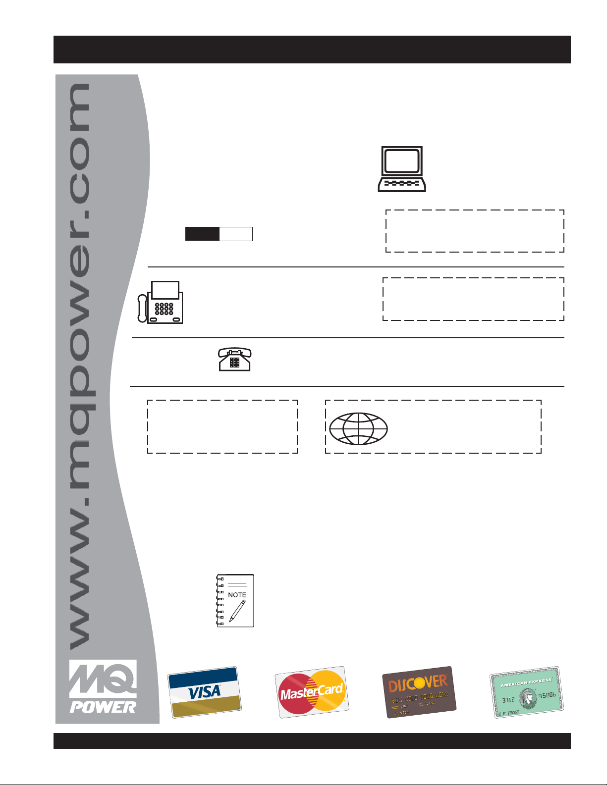
PARTS ORDERING PROCEDURES
Ordering parts has never been easier!
Choose from three easy options:
Effective:
Order via Internet (Dealers Only):
Order parts on-line using Multiquip’s SmartEquip website!
■
View Parts Diagrams
■
Order Parts
Goto www.multiquip.com and click on
Order Par ts
to log in and save!
Order via Fax (Dealers Only):
All customers are welcome to order parts via Fax.
Domestic (US) Customers dial:
Order via Phone:
Non-Dealer Customers:
Contact your local Multiquip Dealer for
parts or call 800-427-1244 for help in
If you have an MQ Account, to obtain a
Username and Password, E-mail us at:
parts@multiquip.com.
To obtain an MQ Account, contact your
Use the
internet
Standard orders
on
Fax
your order in and qualify for a 2% Discount
on
Standard orders
Domestic (US) Dealers Call:
and qualify for a 5% Discount
for all orders which include
for all orders which include
International Customers
their local Multiquip Representatives for
Note: Discounts Are Subject To Change
Note: Discounts Are Subject To Change
should contact
❒❒
❒
❒❒
❒❒
❒
❒❒
❒❒
❒
❒❒
❒❒
❒
❒❒
❒❒
❒
❒❒
www.mqpower.com
DCA-600SSV — OPERATION AND PARTS MANUAL — REV. #0 (07/13/09) — PAGE 5
When ordering parts, please supply:
❒❒
❒
Dealer Account Number
Dealer Name and Address
Shipping Address (if different than billing address)
Return Fax Number
Applicable Model Number
All orders are treated as
and will ship the same day if received prior
WE ACCEPT ALL MAJOR CREDIT CARDS!
❒❒
Standard Orders
Specify Preferred Method of Shipment:
✓
UPS/Fed Ex
■
Priority One
■
Ground
■ Next Day
✓ DHL
✓
Tru ck
Page 6
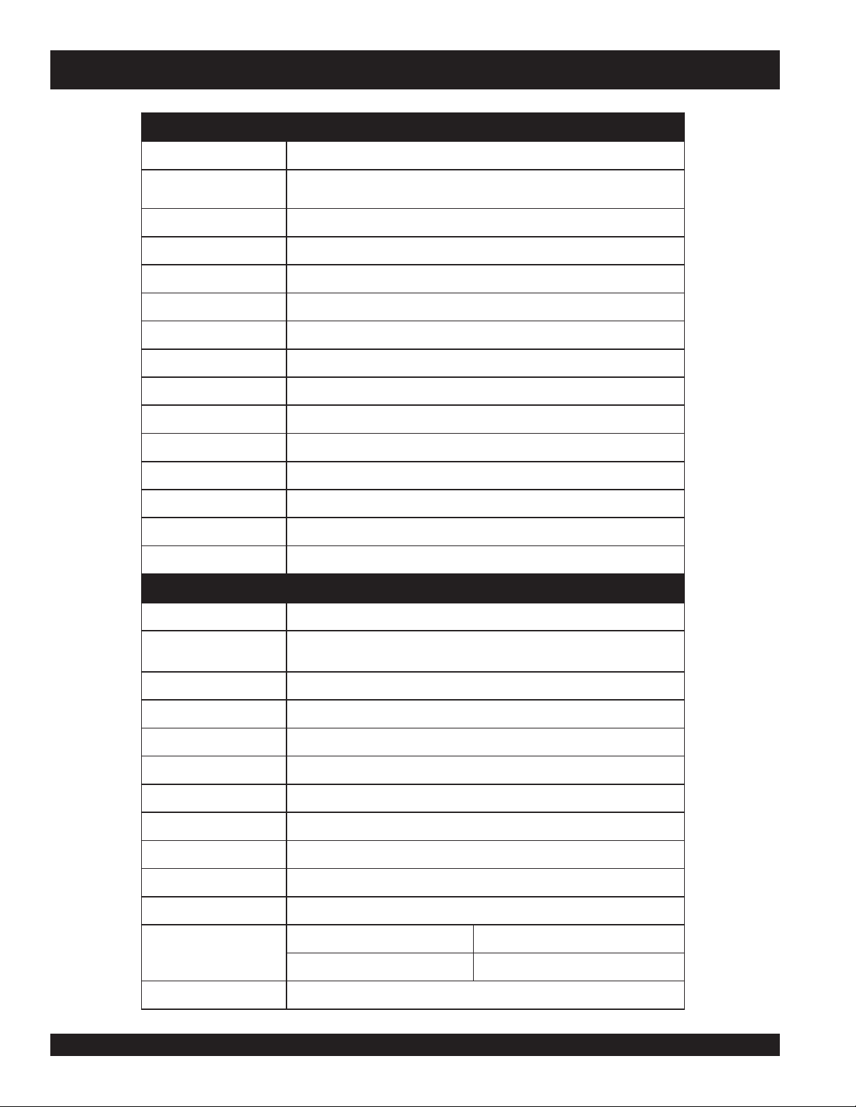
DCA-600SSV — SPECIFICATIONS
ledoMVSS006-ACD
snoitacificepSrotareneG.1elbaT
epyT
rAlartueNhtiwratS
noitcennoCerutam
esahP
tuptuOybdnatS
tuptuOemirP
Ø1—egatloV
Ø3—egatloV
ycneuqerF
deepS
rotcaFrewoP
rewoPCA.xuA
tuptuO/egatloV.xuA
thgieWyrD
thgieWlatoT
,detalitnevfles,dleifgnivloveR
rotarenegsuonorhcnysepytdetcetorpnepo
3
)WK825(AVK066
)WK084(AVK006
,721,021
zH06
mpr0081
8.0
sahPelgniS
bl956,71
V772dna,452,042,931
V084dna,044,614,042,022,802
zH06,e
)2xWk4.2(wK8.4/CAV021
).gk524,7(.sbl963,61
).gk010,8(.s
snoitacificepSenignE.2elbaT
ledoM
epyT
rednilyCfo.oN
s
ekortSxeroB
tuptuOdetaR
tnemecalpsiD
gnitratS
yticapaCtnalooC
yticapaCliOebuL
epyTleuF
yticapaCknaTleuF
noitpmusnoCleuF
21
tarh/)L2.521(.lag1.33 daollluf t
tarh/)L4.56(.lag3.71 daol2/1 tarh/)L6.93(.lag5.01 daol4/1
srednilyc6
EG2461DATATNEPOVLOV
degrahc-obrut,noitcejnitcerid,delooc-retaw,elcyc4
reloocretfariaotriahtiw
)mm561xmm441(.ni05.6x.ni76.5
mpr0081/PH317
021,61(.ni.uc849
)cc
CDV42cirtcelE
)sretil39(.lag6.42
)sretil84(.lag7.
leuFleseiD2#
)sretil094(.lag921
arh/)L7.19(.lag2.42 daol4/3
yrettaB
2xhA002-V21
PAGE 6 — DCA-600SSV — OPERATION AND PARTS MANUAL — REV. #0 (07/13/09)
Page 7
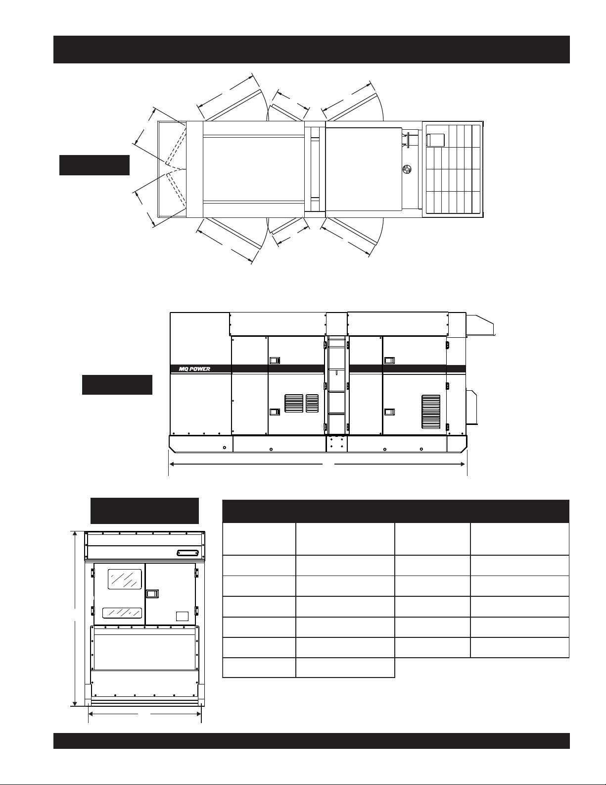
DCA-600SSV — DIMENSIONS (TOP, SIDE AND FRONT)
TOP VIEW
B
A
Figure 1. Dimensions
SIDE VIEW
C
D
G
H
E
F
600
REAR VIEW
(CONTROL PANEL VIEW)
J
K
DCA-600SSV — OPERATION AND PARTS MANUAL — REV. #0 (07/13/09) — PAGE 7
I
SNOISNEMID.3ELBAT
ecnerefeR
retteL
A).mm586(.ni79.62G ).mm044(.ni23.71
B).mm596(
.ni63.72H ).mm000,1(.ni73.93
C).mm000,1(.ni73.93I ).mm007,4(.ni40.581
D).mm044(.ni23.71J ).mm500,2(.ni9.87
E).mm099(
.ni89.83K).mm156,1(.ni56
F).mm099(.ni89.83
).mm(.ninoisnemiDretteLecnerefeR).mm(.ninoisnemiD
Page 8
DCA-600SSV — SAFETY MESSAGE ALERT SYMBOLS
FOR YOUR SAFETY AND THE SAFETY OF OTHERS!
Safety precautions should be followed at all times when
operating this equipment. Failure to read and understand the
Safety Messages and Operating Instructions could result in
injury to yourself and others.
This Owner's Manual has been
NOTE
Before using this generator, ensure that the operating
individual has read and understands all instructions in
this manual.
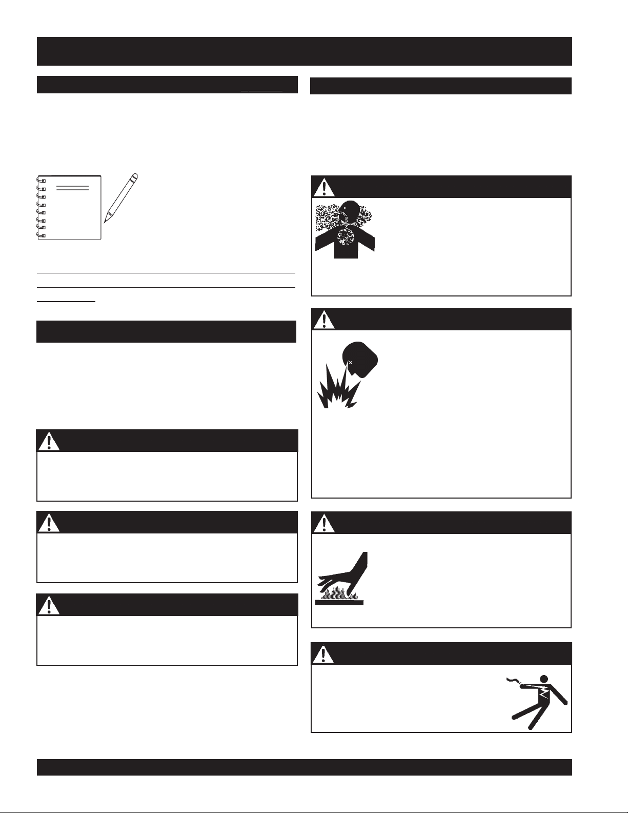
SAFETY MESSAGE ALERT SYMBOLS
The three (3) Safety Messages shown below will inform you
about potential hazards that could injure you or others. The
Safety Messages specifically address the level of exposure
to the operator, and are preceded by one of three words:
DANGER, WARNING, or CAUTION.
DANGER
You WILL be KILLED or SERIOUSLY injured if you
do not follow directions.
developed to provide complete
instructions for the safe and
efficient operation of the
MQPower
WHISPERWATT™ GENERATOR.
Model
DCA-600SSV
HAZARD SYMBOLS
Potential hazards associated with the operation of this
equipment will be referenced with "
appear throughout this manual, and will be referenced in
conjunction with Safety "
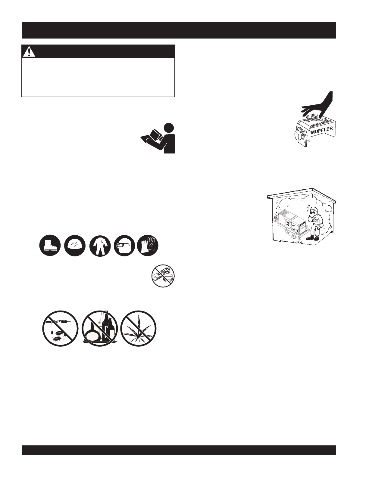
WARNING - LETHAL EXHAUST GASES
equipment in a confined area or enclosed structure that
does not provide ample free flow air.
WARNING - EXPLOSIVE FUEL
DO NOT overfill tank, since spilled fuel could ignite if it
comes into contact with hot engine parts or sparks from
the ignition system. Store fuel in approved containers, in
well-ventilated areas and away from sparks and flames.
NEVER use fuel as a cleaning agent.
Hazard Symbols
Message Alert Symbols
Gasoline engine exhaust gases contain
poisonous carbon monoxide. This gas is
colorless and odorless, and can cause
DEATH
if inhaled. NEVER operate this
Gasoline
its vapors can cause an explosion if
ignited. DO NOT start the engine near
spilled fuel or combustible fluids.
DO NOT fill the fuel tank while the engine
is running or hot.
is extremely flammable, and
" which
".
WARNING
You COULD be KILLED or SERIOUSLY injured if
you do not follow directions.
CAUTION
You CAN be injured if you do not follow directions
PAGE 8 — DCA-600SSV — OPERATION AND PARTS MANUAL — REV. #0 (07/13/09)
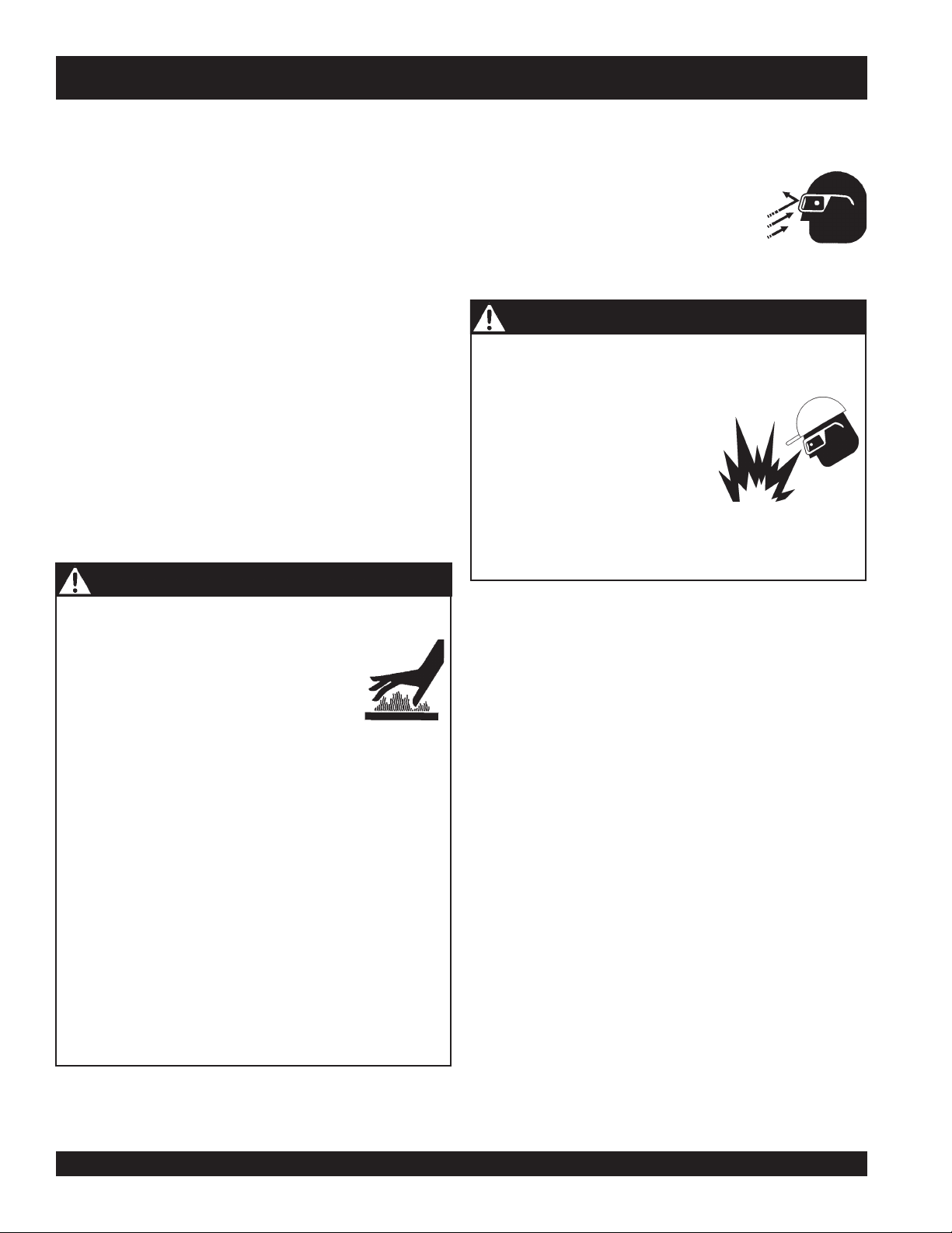
WARNING - BURN HAZARDS
Engine components can generate extreme
heat. To prevent burns, DO NOT touch these
areas while the engine is running or
immediately after operations. NEVER
operate the engine with heat shields or heat
guards removed.
DANGER - ELECTROCUTION HAZARDS
During operation of this generator, there
exists the possibility of
electrical shock or burn,
severe bodily harm
electrocution,
which can cause
or even
DEATH!
Page 9
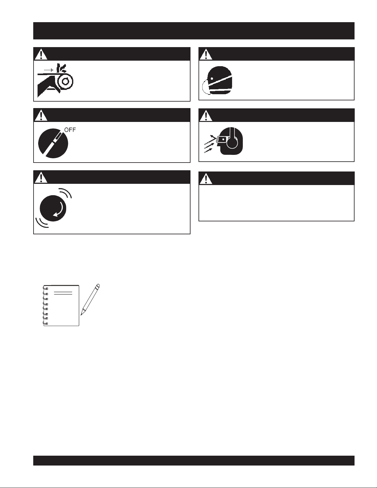
DCA-600SSV — SAFETY MESSAGE ALERT SYMBOLS
WARNING - ROTATING PARTS
NEVER operate equipment with covers,
or guards removed. Keep
hair
and clothing away from all moving
parts to prevent injury.
CAUTION - ACCIDENTAL STARTING
ALWAYS place the Engine ON/OFF
switch in the OFF position and remove
the ignition key when the pump is not in
use.
CAUTION - OVER-SPEED CONDITIONS
NEVER tamper with the factory settings
of the engine governor or settings.
Personal injury and damage to the engine
or equipment can result if operating in
speed ranges above maximum allowable.
fingers, hands
CAUTION - RESPIRATORY HAZARDS
,
CAUTION - SIGHT AND HEARING HAZARDS
CAUTION - EQUIPMENT DAMAGE MESSAGES
Other important messages are provided throughout this
manual to help prevent damage to your generator, other
property, or the surrounding environment.
ALWAYS wear approved
protection.
ALWAYS wear approved
hearing
protection.
respiratory
eye
and
NOTE
This generator, other property,
or the surrounding environment
could be damaged if you do not
follow instructions.
DCA-600SSV — OPERATION AND PARTS MANUAL — REV. #0 (07/13/09) — PAGE 9
Page 10
DCA-600SSV — RULES FOR SAFE OPERATION
■
DANGER - READ THIS MANUAL!
Failure to follow instructions in this manual may lead to
serious injury
operated by trained and qualified personnel only! This
equipment is for industrial use only.
The following safety guidelines should always be used when
operating the
General Safety:
■
DO NOT operate or service this
equipment before reading this entire
manual.
The operator MUST BE familiar with proper safety
precautions and operations techniques before using
generator.
■
This equipment should not be operated by persons under
18 years of age.
■
NEVER operate this equipment without proper protective
clothing, shatterproof glasses, steel-toed boots and other
protective devices required by the job.
or even
DEATH
! This equipment is to be
DCA-600SSV Whisperwatt™ Generator.
ALWAYS check the machine for loosened threads or bolts
before starting.
■
NEVER operate the generator in an explosive atmosphere
or near combustible materials. An explosion or fire could
result causing severe
■
NEVER touch the hot exhaust manifold, muffler
or cylinder. Allow these parts to cool before
servicing engine or generator.
■
High Temperatures – Allow the engine
to cool before performing service and
maintenance functions. Contact with
hot!
components can cause serious
burns.
■
The engine of this generator requires an adequate free
flow of cooling air.
enclosed or narrow area where free flow of the air is
restricted. If the air flow is
restricted it will cause serious
damage to the generator or
engine and may cause injury
to people. The generator
engine gives off DEADLY
carbon monoxide gas.
bodily harm or even death.
NEVER
operate the generator in any
■
■
NEVER operate this equipment when not
feeling well due to fatigue, illness or taking
medicine.
■
NEVER operate this equipment under the influence or
drugs or alcohol.
■
NEVER use accessories or attachments, which are not
recommended by MQ Power for this equipment. Damage
to the equipment and/or injury to user may result.
■
Manufacturer does not assume responsibility for any
accident due to equipment modifications. Unauthorized
equipment modification will void all warranties.
■
Whenever necessary, replace nameplate, operation and
safety decals when they become difficult read.
■
■
■
■
DO NOT place hands or fingers inside generator engine
compartment when engine is running.
NEVER run engine without air filter. Severe engine damage
may occur.
DO NOT leave the generator running in the
unattended.
Refer to the
technical questions or information.
ALWAYS store equipment properly when it is not being
used. Equipment should be stored in a clean, dry location
out of the reach of children.
VOLVO Engine Owner's Manual
manual mode
for engine
PAGE 10 — DCA-600SSV — OPERATION AND PARTS MANUAL — REV. #0 (07/13/09)
Page 11
DCA-600SSV — RULES FOR SAFE OPERATION
Generator Grounding
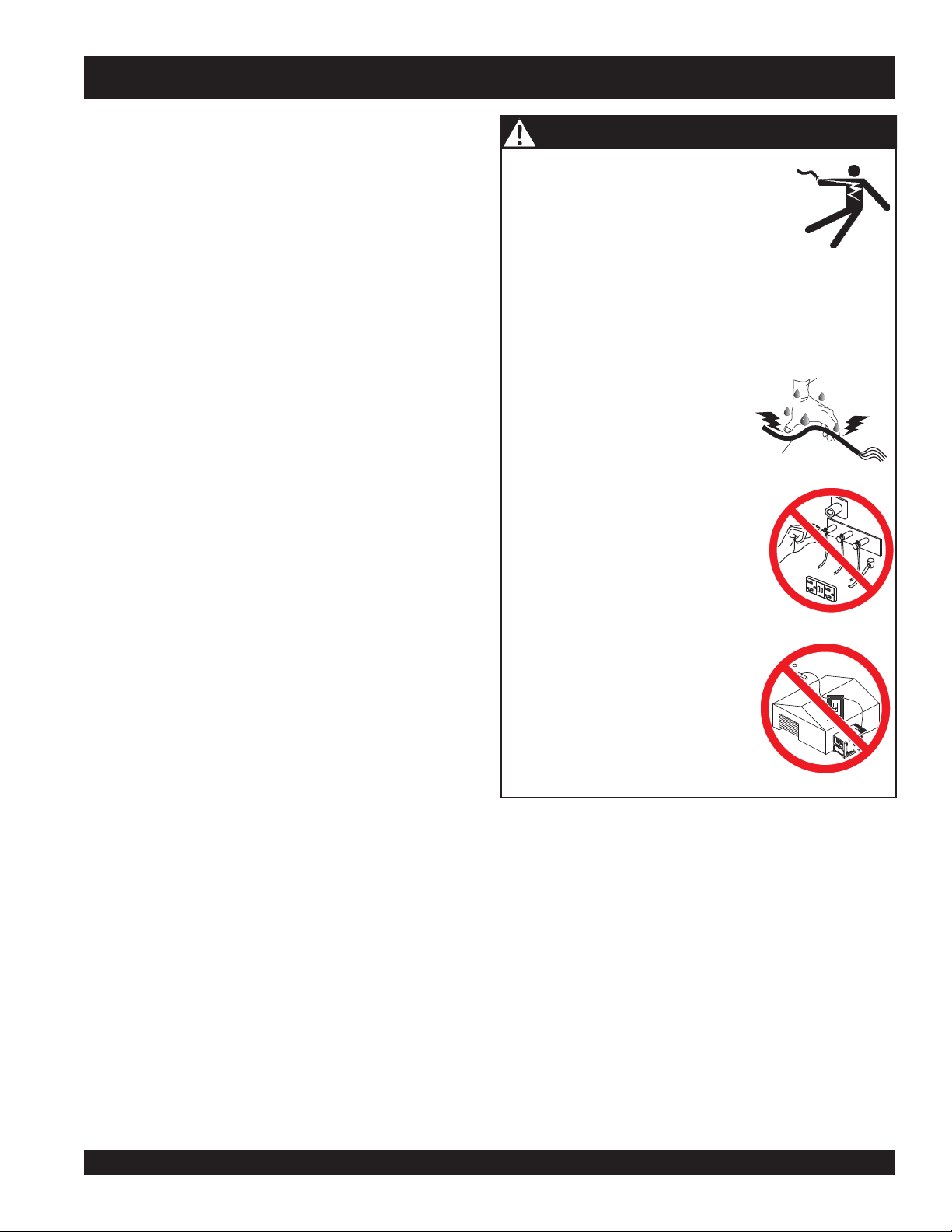
DANGER - ELECTROCUTION HAZARDS
To guard against electrical shock and possible damage to
the equipment, it is important to provide a good EARTH
ground.
During operation of this generator, there
exists the possibility of
electrical shock or burn,
Article 250 (Grounding) of the
National Electrical Code
severe bodily harm
(NEC) provides guide lines for proper grounding and specifies
that the cable ground shall be connected to the grounding
system of the building as close to the point of cable entry
as practical.
The following safety recommendations should also be
followed:
To avoid these hazards:
NEVER use damaged or worn cables when connecting
equipment to the generator. Make sure power connecting
cables are securely connected to the generator’s output
terminals, insufficient tightening of the terminal connections
may cause damage to the generator
■
ALWAYS make sure generator is properly grounded.
■
NEVER use gas piping as an electrical ground.
■
ALWAYS make sure that electrical circuits are properly
grounded
local codes before operating generator. Severe
DEATH!
per the
National Electrical Code
(NEC) and
injury
by electrocution can result from operating an
ungrounded generator.
■
ALWAYS be sure to use the ground terminal (green wire)
when connecting a load to the U,V, and W output
terminal lugs.
and electrical shock.
NEVER grab or touch a live power
cord with wet hands.
NEVER touch output terminals
or
during operation. This is extremely
dangerous. ALWAYS stop the
machine and place the circuit
breaker in the OFF position when
contact with the output terminals is
required.
electrocution,
which can cause
or even
DEATH!
POWER
CORD
(POWER ON)
WET
HANDS
U
N
V
Electrical Safety
■
ALWAYS have a qualified electrician perform the
generator wiring installation.
■
ALWAYS make sure generator installation is accordance
with the
National Electrical Code
(NEC) and local codes
before operating generator.
■
NEVER use a defective or frayed power cable. Check
the cable for cuts in the insulation.
■
NEVER use a extension cord that is frayed or damaged
where the insulation has been cut.
■
ALWAYS make certain that proper extension cord has
been selected for the job. See Table 5.
■
NEVER power cables or cords
■
NEVER
stand in water
while AC power from the generator
lay in wate
r.
is being transfer to a load.
Backfeed to a utility system can
cause
electrocution
and or
property damage. DO NOT connect
to any building's electrical system
except through an approved device
or after building main switch is
opened. ALWAYS have a licensed
electrician perform the installation
DCA-600SSV — OPERATION AND PARTS MANUAL — REV. #0 (07/13/09) — PAGE 11
Page 12
DCA-600SSV— RULES FOR SAFE OPERATION
Maintenance Safety
■
The electrical voltage required to operate the generator
can cause severe injury or even death through physical
contact with live circuits.
before performing maintenance on the generator.
■
NEVER lubricate components or attempt service on a
running machine.
■
ALWAYS disconnect the
before performing service on the generator.
■
Follow all Battery Safety Guidelines listed in this manual
when handleing or servicing the generator.
■
ALWAYS allow the machine a proper amount of time to
cool before servicing.
■
Keep the machinery in proper running condition.
■
Fix damage to the machine immediately and always
replace broken parts.
■
ALWAYS service air cleaner frequently to prevent engine
malfunction.
WARNING - BURN HAZARDS
To prevent burns, DO NOT touch or open any of the below
mentioned components while the engine is
running or immediately after operations.
Always allow sufficient time for the engine
and generator to cool before performing
maintenance.
■
Radiator Cap - Removing the radiator cap while the
engine is hot will result in high pressurized, boiling water
to gush out of the radiator, causing severe scalding to
any persons in the general area of the generator.
■
Coolant Drain Plug - Removing the coolant drain plug
while the engine is hot will result in hot coolant gushing
out of the coolant drain plug, therefore causing severe
scalding to any persons in the general area of the
generator.
Turn all circuit breakers OFF
NEGATIVE battery terminal
Battery Safety
Use the following guidelines when handling the battery:
■
■
■■
■
■■
■■
■
■■
■■
■
■■
■■
■
■■
■■
■
■■
The battery contains acids that can
cause injury to the eyes and skin. To
avoid eye irritation,
glasses.
Use well insulated gloves when picking up the battery.
DANGER - EXPLOSION HAZARDS
The risk of an explosion exists when performing service
on the battery. To avoid
■■
■
DO NOT drop the battery. There
■■
is the possibility of risk that the
battery may explode.
■■
■
DO NOT expose the battery to
■■
open flames, sparks, cigarettes
etc. The battery contains combustible gases and liquids.
If these gases and liquids come in contact with a flame
or spark, an explosion could occur.
ALWAYS keep the battery charged. If the battery is not
charged a buildup of combustible gas will occur.
ALWAYS keep battery charging and cables in good
working condition. Repair or replace all worn cables.
ALWAYS recharge the battery in an vented air
environment, to avoid risk of a dangerous concentration
of combustible gases.
In case the battery liquid (dilute sulfuric acid) comes in
contact with
immediately with plenty of water.
In case the battery liquid (dilute sulfuric acid) comes in
contact with your
plenty of water and contact the nearest doctor or hospital
to seek medical attention.
always
clothing or skin
EYES
wear safety
severe injury
, rinse eyes immediately with
or
DEATH:
, rinse skin or clothing
■
Engine Oil Drain Plug - Removing the engine oil drain
plug while the engine is hot will result in hot oil gushing
out of the oil drain plug, therefore causing severe
scalding to any persons in the general area of the
generator.
PAGE 12 — DCA-600SSV — OPERATION AND PARTS MANUAL — REV. #0 (07/13/09)
Page 13
DCA-600SSV — RULES FOR SAFE OPERATION
■
Towing & Transporting Safety
To reduce the possibility of an accident while transporting
the generator on public roads, always make sure the trailer
that supports the generator and the towing vehicle are in
good operating condition and both units are mechanically
sound.
The following list of safety precautions should be followed
when towing your generator:
CAUTION - FOLLOW TOWING REGULATIONS
Check with your local county or state safety towing
regulations, in addition to meeting
Transportation
towing your generator.
■
ALWAYS shutdown engine before transporting.
■
Tighten both fuel tank caps securely.
■
If generator is mounted on a trailer, make sure trailer
complies with all local and state safety transportation
laws. Follow the listed
guidelines for basic towing techniques.
■
Make sure the hitch and coupling of the towing vehicle
are rated equal to, or greater than the trailer "gross vehicle
weight rating.”
■
ALWAYS inspect the hitch and coupling for wear. NEVER
tow a trailer with defective hitches, couplings, chains etc.
(DOT)
Safety Towing Regulations
Towing & Transporting Safety
Department of
, before
The maximum speed for highway towing is 55 MPH
unless posted otherwise. Recommended off-road towing
is not to exceed 15 MPH or less depending on type of
terrain.
■
Place
while parked.
■
Use the trailer’s swivel jack to adjust the trailer height to
a level position while parked.
■
Avoid sudden stops and starts. This can cause skidding,
or jack-knifing. Smooth, gradual starts and stops will
improve towing.
■
Avoid sharp turns.
■
Trailer should be adjusted to a level position at all times
when towing.
■
Raise and lock trailer wheel stand in up position when
transporting.
■
The maximum speed for highway towing is 55 MPH
unless posted otherwise. Recommended off-road towing
is not to exceed 15 MPH or less depending on type of
terrain.
■
Place
prevent tipping, while parked.
■
Avoid sharp turns to prevent rolling.
■
DO NOT transport generator with fuel in tank.
Emergencies
chock blocks
support blocks
underneath wheel to prevent rolling,
underneath the trailer’s bumper to
■
Check the tire air pressure on both towing vehicle and
trailer.
Also check the tire tread wear on both vehicles.
■
ALWAYS make sure the trailer is equipped with a "Safety
Chain".
■
ALWAYS attach trailer’s safety chains to towing vehicle
properly.
■
ALWAYS make sure the vehicle and trailer directional,
backup, brake, and trailer lights are connected and
working properly.
■
DOT Requirements include the following:
Trailer tires should be inflated to 50 psi cold.
Connect and test electric brake operation.
Secure portable power cables in cable tray with tie
wraps.
DCA-600SSV — OPERATION AND PARTS MANUAL — REV. #0 (07/13/09) — PAGE 13
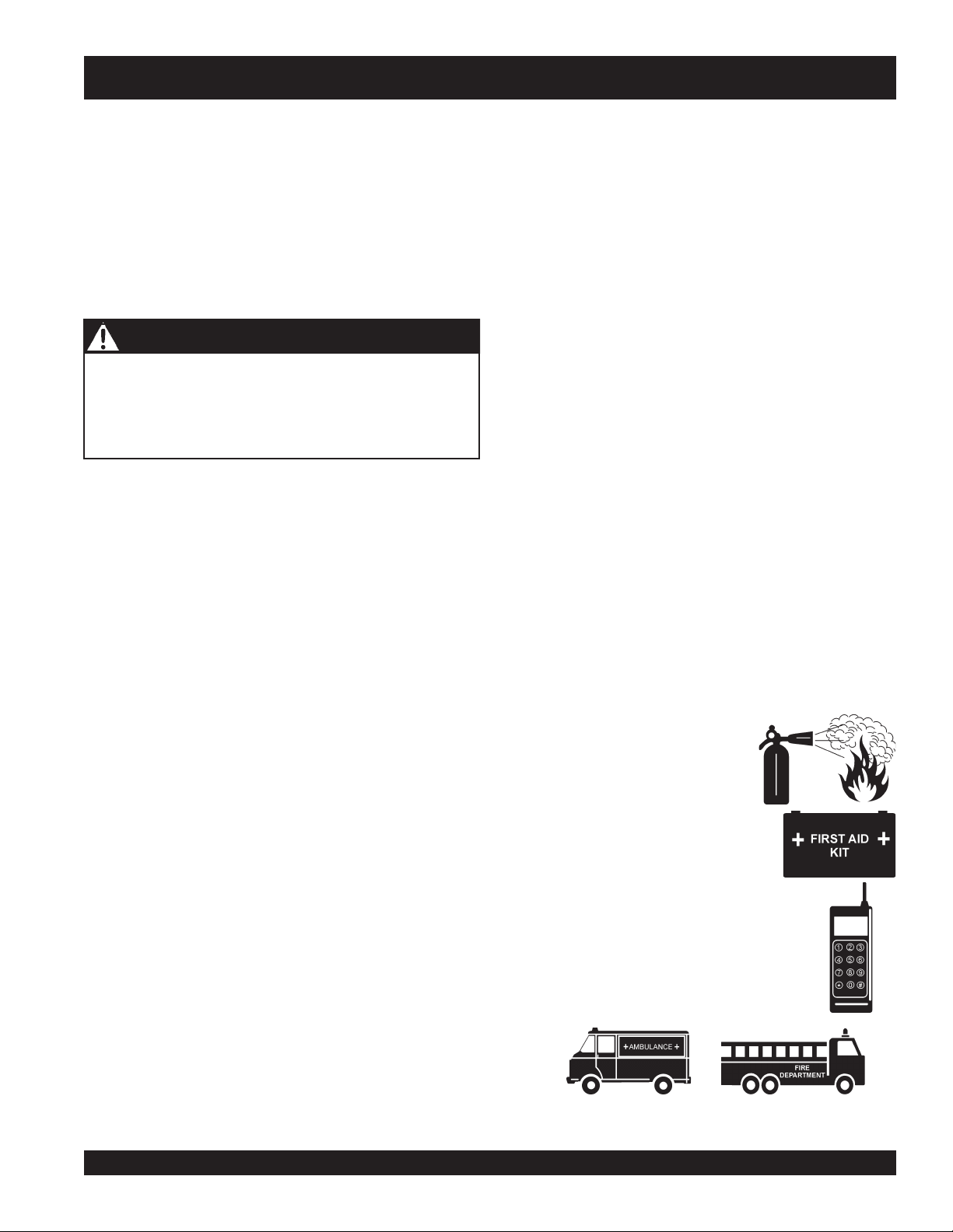
■
■
■
■
ALWAYS know the location of the
nearest
ALWAYS know the location of the
nearest and
ALWAYS know the location of the
nearest phone or
the job site,
ALWAYS have easy access to the phone
numbers of the nearest
and
be invaluable in the case of an emergency.
fire extinguisher
first aid kit
keep a phone on
in case of emergencies.
Fire Department
.
.
Ambulance, Doctor
. This information will
Page 14
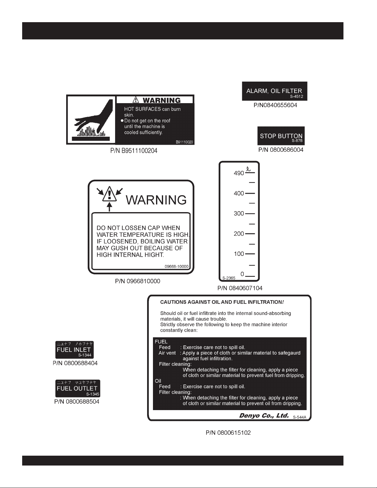
DCA-600SSV — GENERATOR DECALS
Machine Safety Decals
The DCA-600SSV generator is equipped with a number of safety decals. These decals are provided for operator safety and
maintenance information. The illustrations below and on the preceding pages shows the decals as they appear on the machine.
Should any of these decals become unreadable, replacements can be obtained from your dealer.
Figure 2. Generator Decals
PAGE 14 — DCA-600SSV — OPERATION AND PARTS MANUAL — REV. #0 (07/13/09)
Page 15
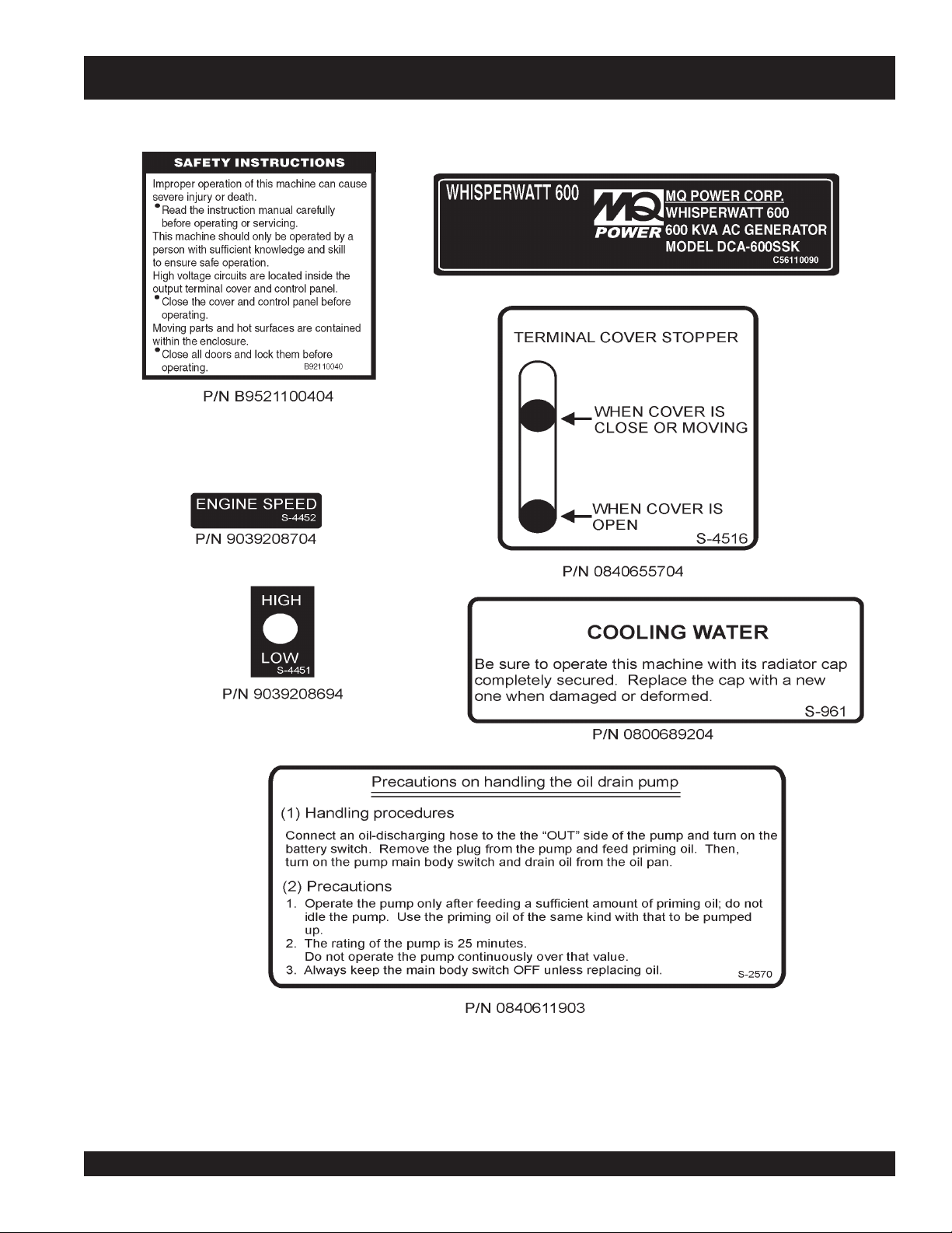
DCA-600SSV — GENERATOR DECALS
Figure 2. Generator Decals
DCA-600SSV — OPERATION AND PARTS MANUAL — REV. #0 (07/13/09) — PAGE 15
Page 16
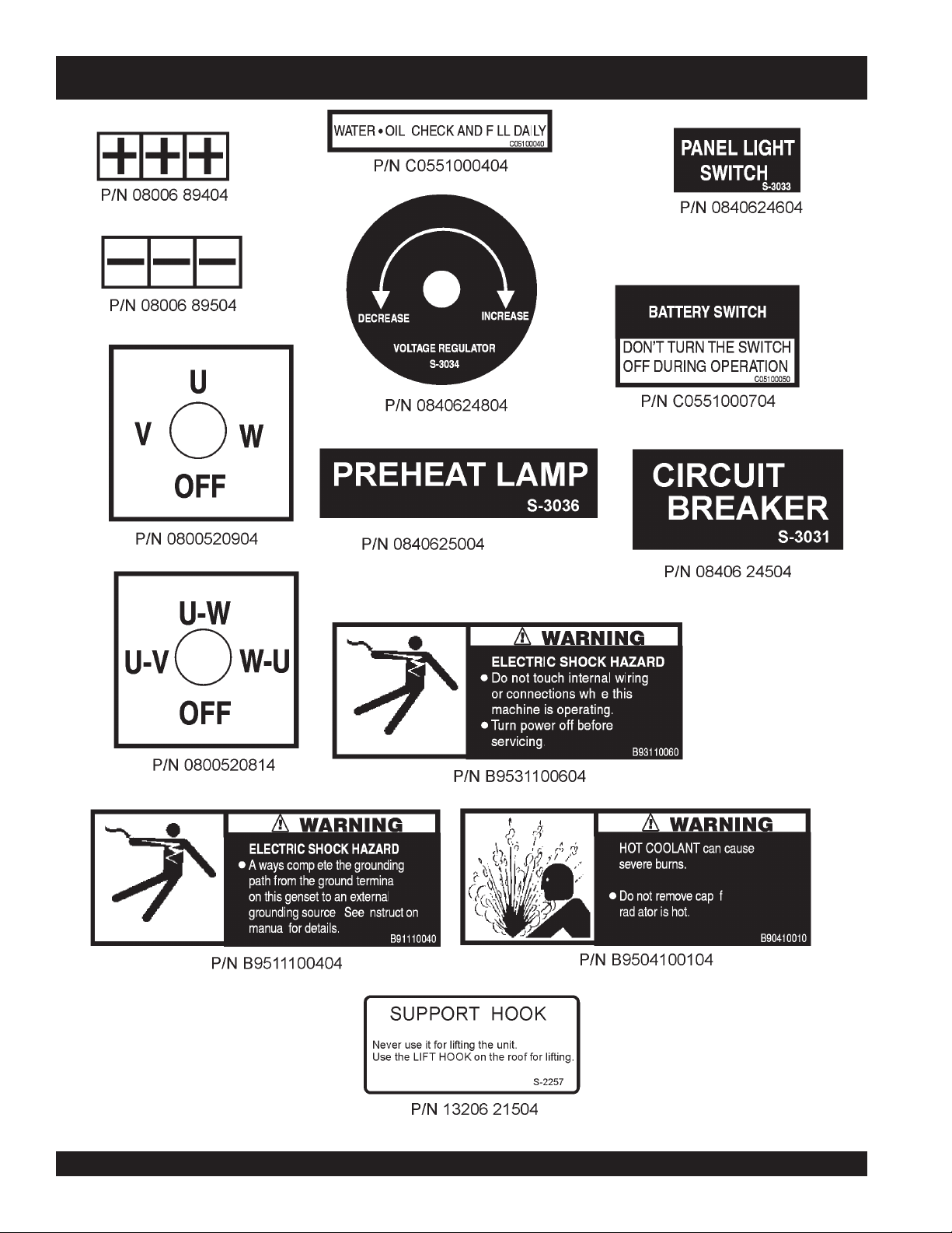
DCA-600SSV — GENERATOR DECALS
Figure 2. Generator Decals
PAGE 16 — DCA-600SSV — OPERATION AND PARTS MANUAL — REV. #0 (07/13/09)
Page 17
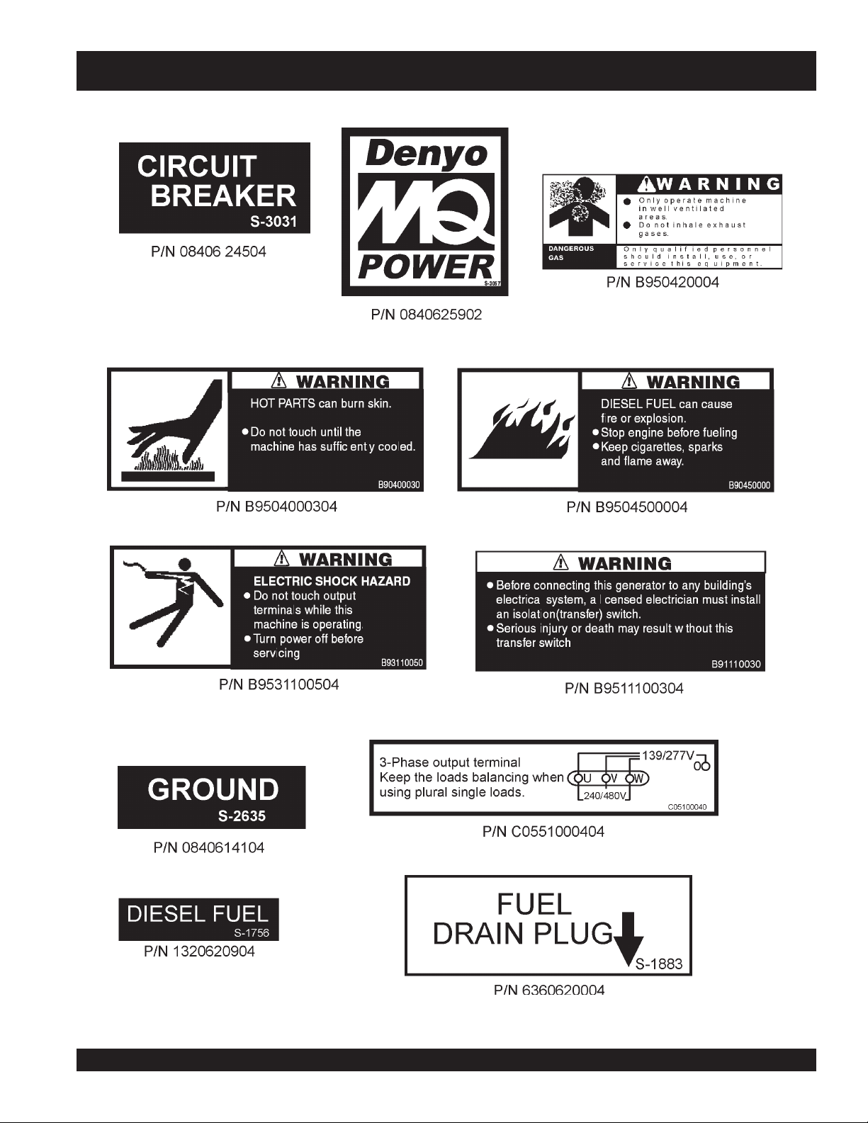
DCA-600SSV — GENERATOR DECALS
Figure 3. Generator Decals
DCA-600SSV — OPERATION AND PARTS MANUAL — REV. #0 (07/13/09) — PAGE 17
Page 18
DCA-600SSV — INSTALLATION
DCA-600SSV — INSTALLATION
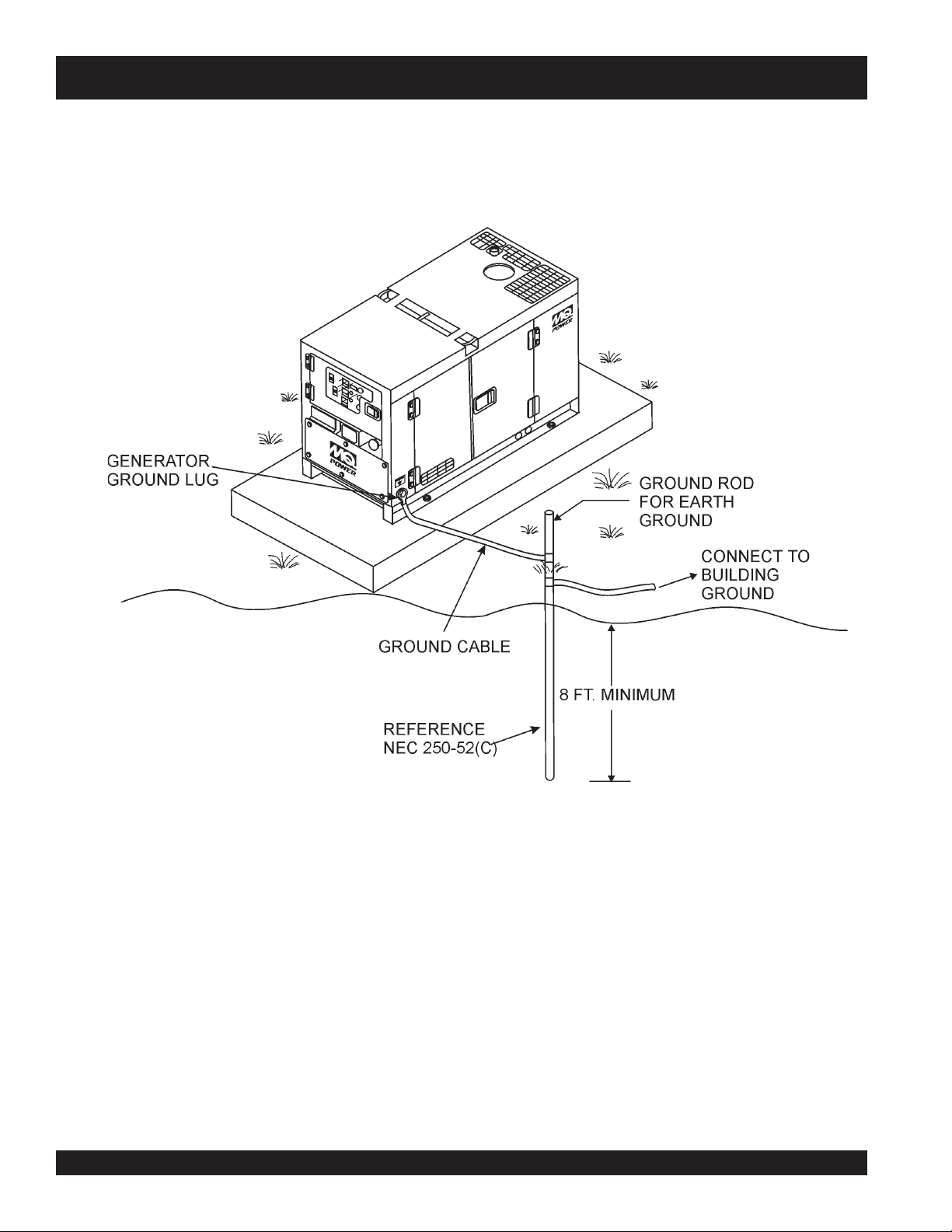
Figure 4. Typical Generator Grounding Application
PAGE 18 — DCA-600SSV — OPERATION AND PARTS MANUAL — REV. #0 (07/13/09)
Page 19
DCA-600SSV — INSTALLATION
Outdoor Installation
Install the generator in a area that is free of
bystanders
generator is on secure level ground so that it cannot slide or
shift around. Also install the generator in a manner so that
the exhaust will not be discharged in the direction of nearby
homes.
The installation site must be relatively free from moisture
and dust. All electrical equipment should be protected from
excessive moisture. Failure to do will result in deterioration
of the insulation and will result in short circuits and grounding.
Foreign materials such as dust, sand, lint and abrasive
materials have a tendency to cause excessive wear to engine
and alternator parts.
Pay close attention to ventilation when operating the
generator inside tunnels and caves. The engine exhaust
contains noxious elements. Engine exhaust must be routed
to a ventilated area.
, and
overhead obstructions
CAUTION - EXHAUST HAZARD
. Make sure the
debris
Generator Grounding
To guard against electrical shock and possible damage to
,
the equipment, it is important to provide a good EARTH
ground.
Article 250 (Grounding) of the National Electrical Code (NEC)
provides guide lines for proper grounding and specifies that
the cable ground shall be connected to the grounding system
of the building as close to the point of cable entry as
practical.
NEC articles 250-64(b) and 250-66 set the following
grounding requirements:
1. Use one of the following wire types to connect the
generator to earth ground.
a. Copper - 10 AWG (5.3 mm2) or larger.
b. Aluminum - 8 AWG (8.4 mm2) or larger.
2. When grounding the generator (Figure 4) connect the
ground cable between the lock washer and the nut on
the generator and tighten the nut fully. Connect the other
end of the ground cable to earth ground.
3. NEC article 250-52(c) specifies that the earth ground
rod should be buried aminimum of 8 ft. into the ground.
Indoor Installation
Exhaust gases from diesel engines are extremely poisonous.
Whenever an engine is installed indoors the exhaust fumes
must be vented to the outside. The engine should be installed
at least two feet from any outside wall. Using an exhaust
pipe which is too long or too small can cause excessive
back pressure which will cause the engine to heat excessively
and possibly burn the valves.
Mounting
The generator must be mounted on a solid foundation (such
as concrete) and set firmly on the foundation to isolate
vibration of the generator when it is running. The generator
must set at least 6 inches above the floor or grade level (in
accordance to NFPA 110, Chapter 5-4.1). DO NOT remove
the metal skids on the bottom of the generator. They are to
resist damage to the bottom of the generator and to maintain
alignment.
NOTE
When connecting the generator to
any buildings electrical system
ALWAYS consult with a licensed
electrician.
DCA-600SSV — OPERATION AND PARTS MANUAL — REV. #0 (07/13/09) — PAGE 19
Page 20

DCA-600SSV — GENERAL INFORMATION
DCA-600SSVWhisperwatt™ Series Familiarization
Generator
The MQ Power Model DCA-600SSV is a 528 kW
generator
(Figure 5) that is designed as a high quality portable (requires
a trailer for transport) power source for telecom sites, lighting
facilities, power tools, submersible pumps and other
industrial and construction machinery.
Engine Operating Panel
The “Engine Operating Panel” is provided with the following:
■■
Tachometer/Hour Meter Gauge
■
■■
■■
Water Temperature Gauge / Water Temp. Alarm Lamp
■
■■
■■
Oil Pressure Gauge / Oil Pressure Alarm Lamp
■
■■
■■
Charging Alarm Lamp
■
■■
■■
■
Fuel Level Gauge / Low Fuel Warning Alarm Lamp
■■
■■
■
Pre-Heat Button / Pre-Heat Lamp
■■
■■
■
Air Filter Alarm Lamp
■■
■■
■
Engine Speed Switch
■■
■■
■
Battery Switch
■■
■■
■
Emergency Stop Button
■■
Generator Control Panel
The “Generator Control Panel” is provided with the following:
■■
■
Frequency Meter (Hz)
■■
■■
■
AC Ammeter (Amps)
■■
■■
■
AC Voltmeter (Volts)
■■
■■
■
Ammeter Change-Over Switch
■■
■■
■
Voltmeter Change-Over Switch
■■
■■
■
Voltage Regulator
■■
■■
■
Panel Light/Panel Light Switch
■■
■■
■
3-Pole, 1,600 amp Main Circuit Breaker
■■
■■
■
Engine Control Unit (Computer Controlled)
■■
■■
■
“Control Box” (Located Behind Gen. Control Panel)
■■
■■
■
Automatic Voltage Regulator
■■
■■
■
Current Transformer
■■
■■
■
Over-Current Relay
■■
■■
■
Voltage Rectifer
■■
■■
■
Starter Relay
■■
■■
■
Voltage Change-over Board
■■
Open Delta Excitation System
The DCA-600SSV generator is equipped with the state of
the art "
system consist of an electrically independent winding wound
among stationary windings of the AC output section.
There are four connections of the open delta A, B, C and D.
During steady state loads, the power from the voltage
regulator is supplied from the parallel connections of A to B,
A to D, and C to D. These three phases of the voltage input
to the voltage regulator are then rectified and are the
excitation current for the exciter section.
When a heavy load, such as a motor starting or a short
circuit occurs, the automatic voltage regulator (AVR)
switches the configuration of the open delta to the series
connection of B to C. This has the effect of adding the
voltages of each phase to provide higher excitation to the
exciter section and thus better voltage response during the
application of heavy loads.
The connections of the AVR to the AC output windings are
for sensing only. No power is required from these windings.
The open-delta design provides virtually unlimited excitation
current, offering maximum motor starting capabilities. The
excitation does not have a "
according the demands of the required load.
Engine
The DCA-600SSV is powered by a 4 cycle, water cooled,
turbocharged
Engine
requirement for the generator. Reference Table 2 for engine
specifications.
In keeping with MQ Power's policy of constantly improving
its products, the specifications quoted herein are subject to
change without prior notice.
Electronic Governor System
The electric governor system controls the RPMs of the engine. When the engine demand increases or decreases, the
governor system regulates the frequency variation to ±.25%.
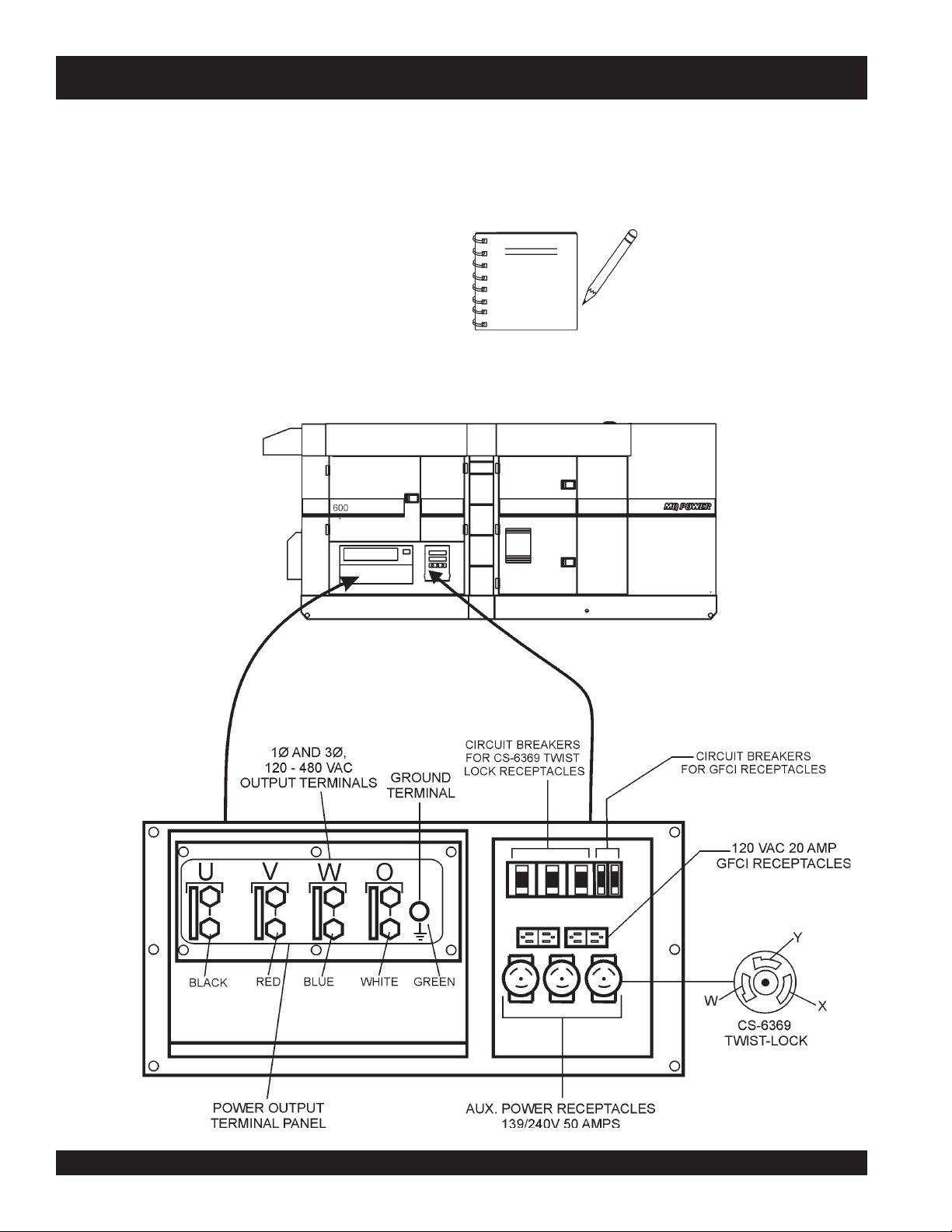
Output Terminal Panel
Extension Cables
The “Output Terminal Panel” is provided with the following:
■■
■
Three 120/240V output receptacles (CS-6369), 50A
■■
■■
■
Three auxilliary circuit breakers, 50A
■■
■■
■
Two 120V output receptacles (GFCI), 20A
■■
■■
■
Two GFCI circuit breakers, 20A
■■
■■
■
Four output terminal boards (3Ø power)
■■
■■
■
Ground terminal
■■
■■
■
Battery Charger (Optional)
■■
■■
■
Water Heater (Optional)
■■
When electric power is to be provided to various tools or
loads at some distance from the generator, extension cords
are normally used. Cables should be sized to allow for
distance in length and amperage so that the voltage drop
between the generator and point of use (load) is held to a
minimum. Use the cable selection chart (Table 6) as a guide
for selecting proper extension cable size.
Open-Delta
" excitation system. The open delta
fixed ceiling
" and responds
VOLVO Model PENTA TAD1642GE Diesel
. This engine is designed to meet every performance
PAGE 20 — DCA-600SSV — OPERATION AND PARTS MANUAL — REV. #0 (07/13/09)
Page 21
DCA-600SSV — MAJOR COMPONENTS
DCA-600SSV — MAJOR COMPONENTS
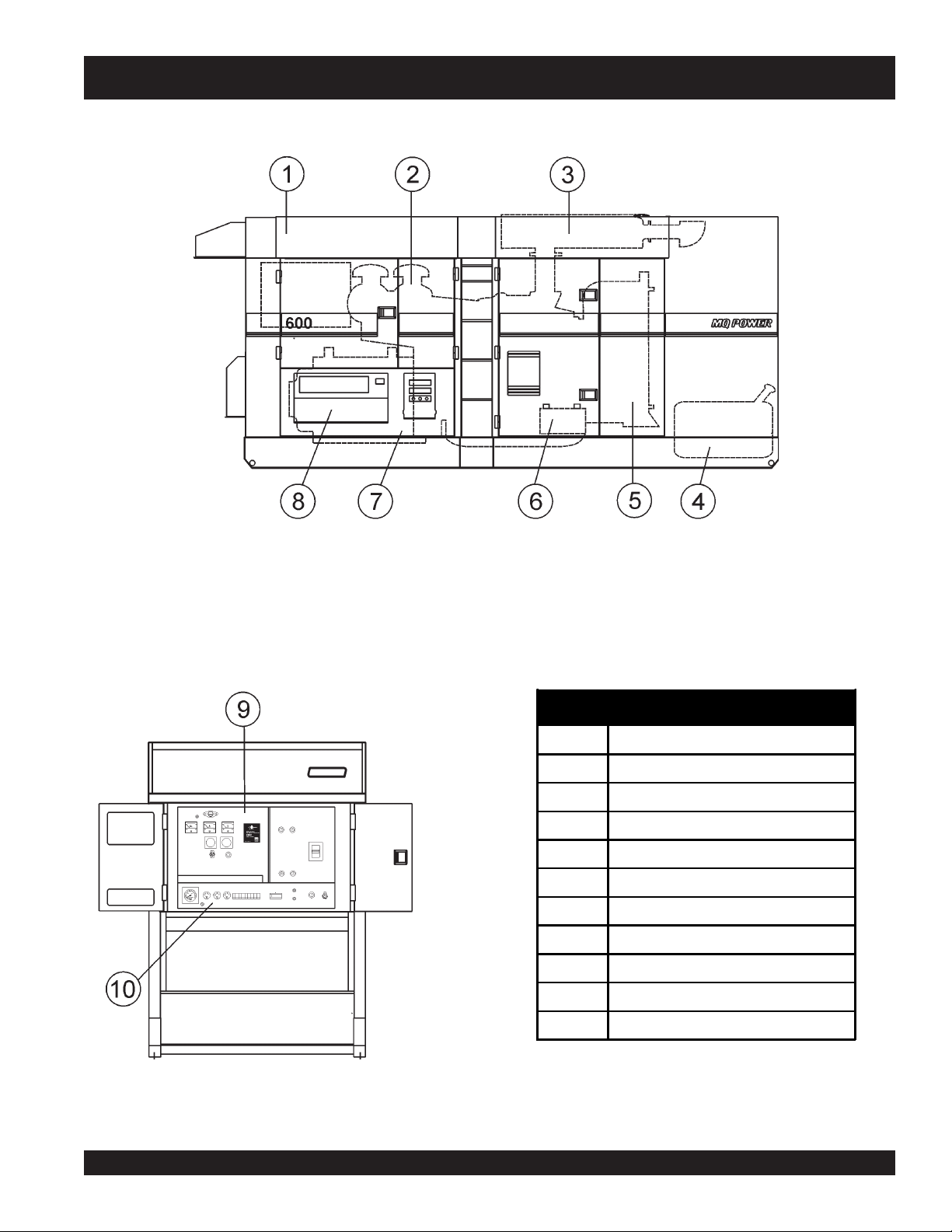
Tabl e 4. Generator Major Components
ITEM NO. DESCRIPTION
1 Enclosure Assembly
2 Air Cleaner Assembly
3 Muffler Assembly
4 Fuel Tank Assembly
5 Engine and Radiator Assembly
6 Battery Assembly
7 Generator Assembly
8 Output Terminal Assembly
9 Generator Control Panel Assembly
10 Engine Operating Panel Assembly
Figure 5. Major Components
DCA-600SSV — OPERATION AND PARTS MANUAL — REV. #0 (07/13/09) — PAGE 21
Page 22

DCA-600SSV — GENERATOR CONTROL PANEL
1
3
HZ
6
2
11
10
4
A
5
V
14
AUTO
MANUAL
OFF/RESET
LOW OIL PRESSURE
HIGH COOLANT TEMPERATURE
OVERCRANK
OVERSPEED
ENGINE RUNNING
MOOOOO-20001Q
7
8
9
13
12
Figure 6. Generator Control Panel
The definitions below describe the controls and functions of
the DCA-600SSV "
Control Panel
" (Figure 6).
1. Pilot Lamp – Indicates that the generator is working
properly.
2. Panel Light – Normally used in dark areas or at night
time. When activated, panel lights will illuminate. When
lit this light will make it easier to read the meters and
gauges. When the generator is not in use be sure to
turn the panel light switch to the OFF position.
3. Frequency Meter – Indicates the output frequency in
hertz (Hz). Normally 60 Hz ±1 Hz .
4. AC Ammeter – Indicates the amount of current the
6. Ammeter Change-Over Switch – This switch allows
the AC ammeter to indicate the current flowing to the
load connected to any phase of the output terminals,
or to be switched off.
7. Voltmeter Change-Over Switch – This switch allows
the AC voltmeter to indicate phase to phase voltage
between any two phases of the output terminals or to
be switched off
8. Panel Light Switch – When activated, this switch will
turn on the luminate the control panel.
9. Voltage Regulator Control – Allows manual
adjustment of the generator’s output voltage
load is drawing from the generator.
5. AC Voltmeter – Indicates the single phase output
voltage present at the UVWO terminals. .
PAGE 22 — DCA-600SSV — OPERATION AND PARTS MANUAL — REV. #0 (07/13/09)
Page 23
DCA-600SSV — GENERATOR CONTROL PANEL
10. Circuit Breaker OFF Lamp – When the circuit
breaker ON switch is placed in the OFF position this
lamp will be turned OFF.
11. Circuit Breaker ON Lamp – When the circuit breaker
ON switch is placed in the ON position this lamp will
be turned ON.
12. Circuit Breaker OFF Switch – Press this switch to
place the 1600 amp circuit breaker in the open (OFF)
position.
13. Circuit Breaker ON Switch – Press this switch to
place the 1600 amp circuit breaker in the closed (ON)
position.
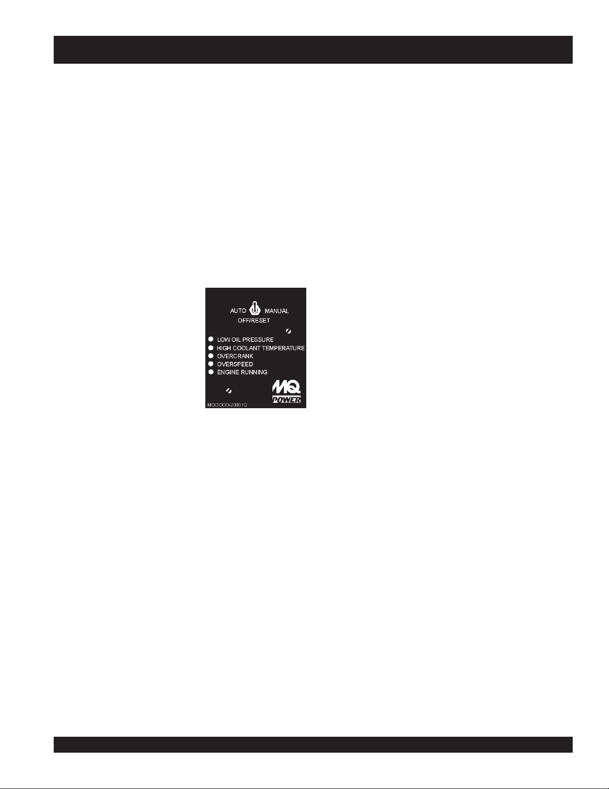
14. Auto On/Off Engine Controller (MPEC) – This
controller has a vertical row of status LED's (inset),
that when lit, indicates that an
engine malfunction (fault) has
been detected. When a fault
has been detected the engine
controller will evaluate the fault
and all major faults will
shutdown the generator.
During
MPEC will attempt to crank
the engine for 10 seconds
before disengaging.
During
the engine for 10 seconds before disengaging. If the engine
does not engage (start) by the third attempt, the engine will
be shutdown by the engine controller’s " Over Crank
Protection" mode. If the engine engages at a speed (RPM's)
that is not safe, the controller will shutdown the engine by
initializing the "
cranking cycle
cranking cycle
Over Speed Protection
, The
, The MPEC will attempt to crank
" mode.
If the generator is to be connected to a building’s AC
power source via an automatic transfer switch
(isolation), place the switch in the AUTO position. In
this position, should an outage occur, the automatic
transfer switch (ATS) will start the generator
automatically via the generator’s auto-start contacts
connected to the ATS’s start contacts. Please refer to
your ATS installation manual for further instructions for
the correct installation of the auto-start contacts of the
generator to the ATS.
B. Low Oil Pressure – Indicates the engine pressure
has fallen below 15 psi. The oil pressure is detected
using variable resistive values from the oil pressure
sending unit. This is considered a
shut down the generator.
C. High Coolant Temperature – Indicates the engine
temperature has exceeded 215°F. The engine
temperature is detected using variable resistive values
from the temperature sending unit. This is considered
a
major
D. Overcrank Shutdown – Indicates the unit has
attempted to be started a pre- programmed number of
times, and has failed to start. The number of cycles
and duration are programmable. Typical programmable
start settings is 3 cycles with a 10 second duration.
This is considered a
the generator.
E. Overspeed Shutdown – Indicates that the engine is
running at an unsafe speed. This is considered a
fault.
F. Engine Running – Indicates that engine is running at
a safe operating speed.
major
fault and will
fault and will shut down the generator.
major
fault and will shut down
major
Also the MPEC will shutdown the generator in the event of
low oil pressure, high coolant temperature, low coolant level,
and loss of magnetic pickup. These conditions can be
observed by monitoring the LED status indicators on the
front of the MPEC module.
A. Off/Manual/Auto Switch – This switch controls the
running of the generator. If this switch is left in the "OFF"
position, the generator will not run. When this switch is
set to the
immediately.
manual
DCA-600SSV — OPERATION AND PARTS MANUAL — REV. #0 (07/13/09) — PAGE 23
position, the generator will start
Page 24
DCA-600SSV — ENGINE OPERATING PANEL
1
TACHOMETER
11
5
6
7
WATERTEMP.
OILPRESS. FUEL LEVEL
2
CHARGE
AIRFILTER
BATTERY SWITCH
ON
OFF
8
3
PRE-HEAT
LAMP
PRE-HEAT
BUTTON
9
4
EMERGENCY
STOP
ENGINE SPEED
HIGH
LOW
10
Figure 7. Engine Operating Panels
PAGE 24 — DCA-600SSV — OPERATION AND PARTS MANUAL — REV. #0 (07/13/09)
Page 25
DCA-600SSV — ENGINE OPERATING PANEL
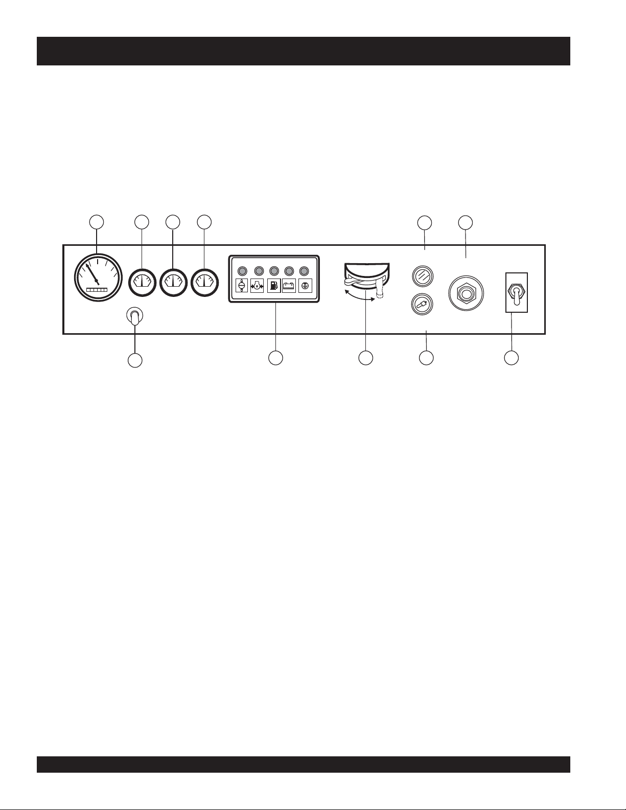
The definitions below describe the controls and functions of the
DCA-600SSV "
Engine Operating Panels
" (Figure 7).
1. Tachometer – Indicates engine speed in RPM’s for 60 Hz
operation. This meter should indicate 1800 RPM’s when
the rated load is applied. In addition a built in hour meter
will record the number of operational hours that the
generator has been in use.
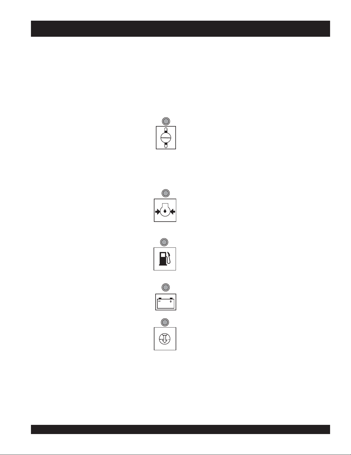
2. Engine Warning Display (LED) Module – This module
display’s the following engine failures:
A. Overheat Lamp – This lamp goes ON when
the cooling water temperature rises abnormally.
If the lamp goes ON during normal operation of
the generator, the emergency shutdown device
will stop the engine automatically.
WATER TEMP.
3. Pre-Heat Lamp – Indicates that the glow plugs of the
diesel engine are hot and the engine is ready to be started.
4. Emergency Stop Button – Push this button inward to
stop the engine in the event of an emergency. DO NOT
use this button as a normal means of stopping the engine.
5. Oil Pressure Gauge – During normal operation this gauge
be should read in the “GREEN” zone. When starting the
generator the oil pressure mar read a little bit higher, but
after the engine warms up the oil pressure should return to
the green zone.
6. Water Temperature Gauge – During normal operation
this gauge be should read in the “GREEN” zone.
7. Fuel Level Gauge – Indicates amount of diesel fuel
remaining.
8. Battery Switch – This switch should be set to the ON
B. Low Oil Pressure Lamp – During normal operation of the
generator this lamp should remain OFF. When the AutoOFF/Reset-Manual switch is set to the
“Manual” position to start the engine, the lamp
will illuminate. After the oil pressure rises after
start-up the lamp will go OFF. If this lamp is
position during normal operation. When the engine has
been stop, place this switch in the OFF position. DO NOT
turn this switch during normal operation, it could cause
damage to the electrical equipment.
9. Preheat Switch – Press on to heat glow plugs in cold
weather conditions.
ever illuminated (ON) during normal operation
of the generator, the emergency shutdown
device will stop the engine automatically.
C. Low Fuel Level Lamp – When this lamp is
ON, it is time to stop the engine and add fuel.
OIL PRESS.
10. Engine Speed Switch – This switch changes the engine
speed from idle to normal.
Hour Meter Switch - Press this pushbutton switch to
11.
activate hour meter. Indicates the number hours
equipment has been in operational use.
Remember to let the engine cool before
adding fuel.
FUEL LEVEL
D. Charge Lamp – This lamp goes ON when
the electrical charging system is not working
properly.
E. Clogged Air Filter Lamp – This lamp goes
ON when the air filter is clogged. If this lamp
goes ON during normal operation of the
generator, stop the engine and replace the air
filter.
DCA-600SSV — OPERATION AND PARTS MANUAL — REV. #0 (07/13/09) — PAGE 25
BATTERY
AIR FILTER
Page 26
DCA-600SSV — OUTPUT TERMINAL FAMILIARIZATION
Output Terminal Familiarization
The “
Output Terminal Panel
the following:
Three 240/139V output receptacles, 50 amp
Three AUX. circuit breakers 240V @50 amps
Two 120V GFCI receptacles, 20 amp
Two (2) GFCI circuit breakers 120V@ 20 amps
Eight (16) output terminal lugs
Figure 8. Output Terminal Panel
” (Figure 8) is provided with
Output Terminal Panel
Shown below (Figure 8) is the
up on the cover to gain access to receptacles and terminal
lugs.
NOTE
Output Terminal Panel
Terminal legs "O" and "Ground"
are considered
bonded grounds
, lift
.
PAGE 26 — DCA-600SSV — OPERATION AND PARTS MANUAL — REV. #0 (07/13/09)
Page 27
DCA-600SSV — OUTPUT TERMINAL PANEL FAMILIARIZATION
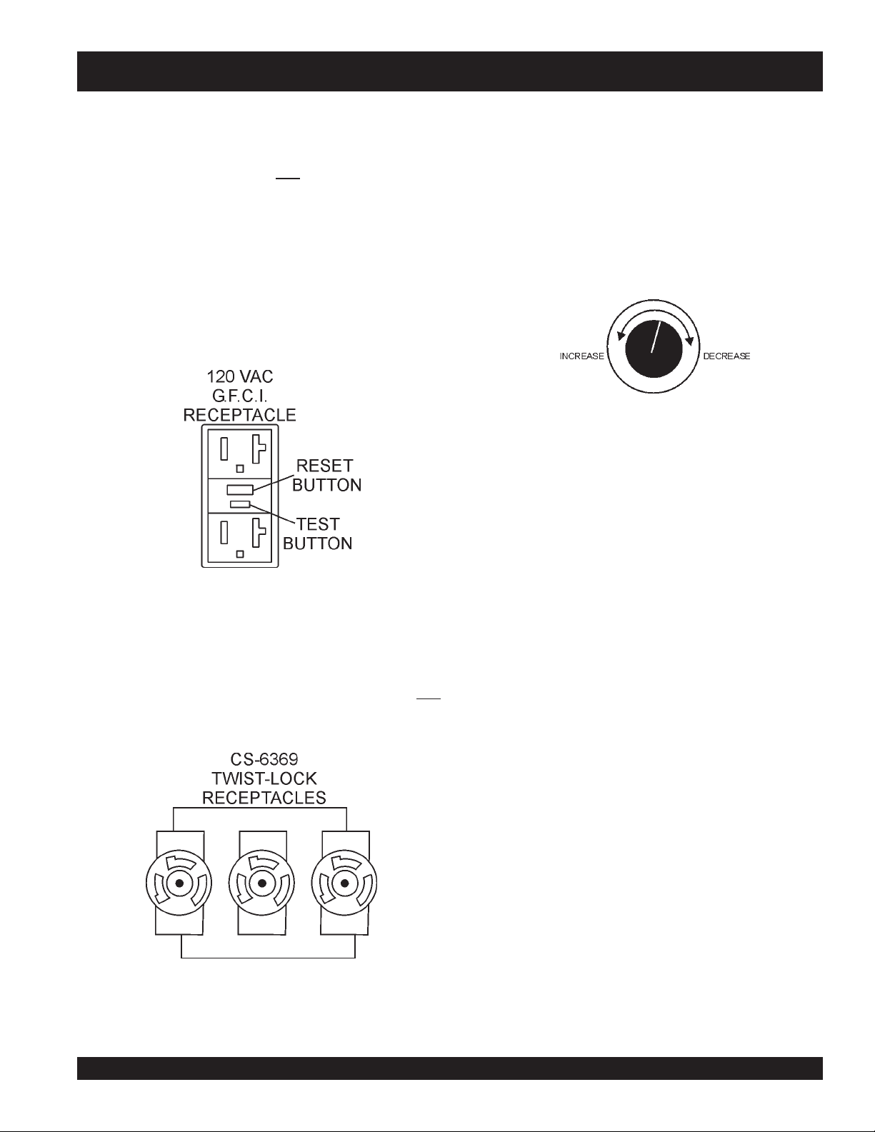
120 VAC GFCI Receptacles
There are two 120 VAC, 20 amp GFCI (Duplex Nema 5-20R)
recepacles provided on the output terminal panel. These
receptacles can be accessed in any
board
position. Each receptacle is protected by a 20 amp
circuit breaker. These breakers are located directly above
the GFCI receptacles. Remember the load output (current)
of both GFCI receptacles is dependent on the load
requirements of the UVWO terminals.
Pressing the
being tripped. Pressing the "
the center of the receptacle will check the GFCI function.
Both receptacles should be tested at least once a month.
reset
button resets the GFCI receptacle after
Test Button
voltage change-over
" (See Figure 9) in
Each auxiliary receptacle is protected by a 50 amp circuit
breaker. These breakers are located directly above the GFCI
receptacles. Remember the load output (current) on all three
receptacles is dependent on the load requirements of the
UVWO terminals.
Turn the
control panel to obtain the desired voltage. Turning the knob
clockwise will
clockwise will
Figure 11. Voltage Regulator Control Knob
voltage regulator control knob
increase
decrease
the voltage, turning the knob counter-
the voltage.
(Figure 11) on the
Figure 9 G.F.C.I. Receptacle
Twist Lock Dual Voltage 240/139 VAC Receptacles
There are three 240/139 VAC, 50 amp auxiliary twist-lock
(CS-6369) receptacles (Figure 10) provided on the output
terminal panel. These receptacles can be accessed in any
voltage change-over board
Figure 10. 240/139 VAC Twist-Lock
Auxiliary Receptacles
position.
DCA-600SSV — OPERATION AND PARTS MANUAL — REV. #0 (07/13/09) — PAGE 27
Page 28
DCA-600SSV — OUTPUT TERMINAL PANEL FAMILIARIZATION
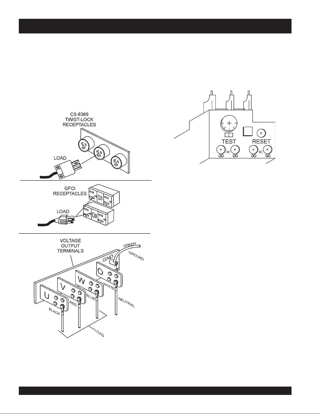
Connecting Loads
Loads can be connected to the generator by the UVWO terminal
lugs or the convenience receptacles. (See Figure 12). Make
sure to read the operation manual before attempting to connect
a load to the generator.
To protect the UVWO output terminals from overload, a 3pole, 1,600 amp,
sure to switch
prior to starting the engine.
main
circuit breaker is provided. Make
ALL
circuit breakers to the "OFF" position
Over Current Relay
An
over current relay
circuit breaker. In the event of an overload, both the circuit
breaker and the over current relay may trip. If the circuit
breaker can not be reset, the
rent relay must be pressed. The over current relay is located in the control box.
(Figure 13) is connected to the main
reset button
Figure 13. Over Current Relay
on the over cur-
Figure 12. Connecting Loads
Maximum Power Output (KW)
The entire load connected to the UVWO output terminal lugs,
duplex and auxiliary receptacles must not exceed 528 kW in
standby or 480 kW in prime output.
PAGE 28 — DCA-600SSV — OPERATION AND PARTS MANUAL — REV. #0 (07/13/09)
Page 29
DCA-600SSV— LOAD APPLICATION
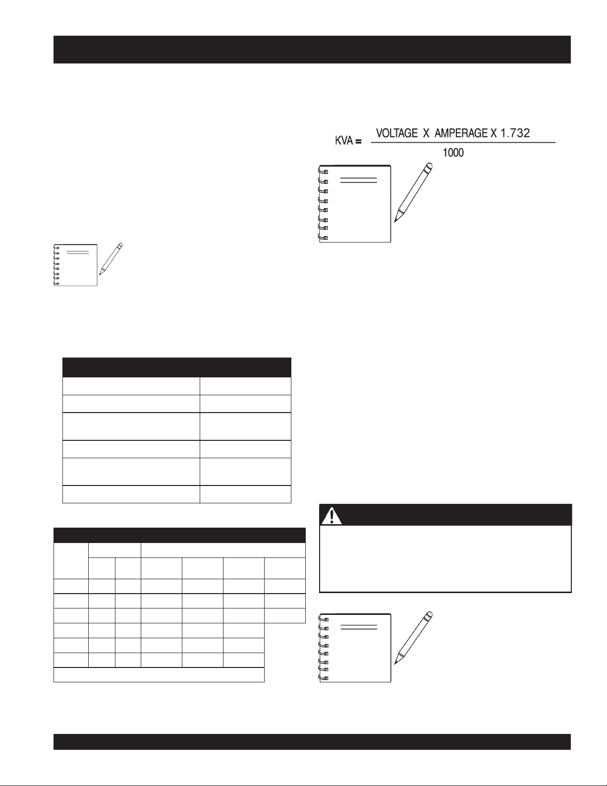
Single Phase Load
Always be sure to check the nameplate on the generator
and equipment to insure the wattage, amperage and
Three Phase Load
When calculating the power requirements for 3-phase power
use the following equation:
frequency requirements are satisfactorily supplied by the
generator for operating the equipment.
Generally, the wattage listed on the nameplate of the
equipment is its rated output. Equipment may require 130—
150% more wattage than the rating on the nameplate, as
the wattage is influenced by the efficiency, power factor and
NOTE
starting system of the equipment.
If wattage is not given on the equipment's
NOTE
name plate, approximate wattage may be
determined by multiplying nameplate
voltage by the nameplate amperage.
An inadequate size connecting cable which cannot carry the
required load can cause a voltage drop which can burn out
the appliance or tool and overheat the cable. See Table 5.
WATTS = VOLTAGE x AMPERAGE
The power factor of this generator is 0.8. See Table 5 below
when connecting loads.
daoLyBrotcaFrewoP.5elbaT
daoLfOepyTrotcaFrewoP
srotomnoitcudniesahp-elgniS57.0-4.0
tnecsednacni,sretaehcirtcelE
spmal
m,spmaltnecseroulF9.0-4.0
tnempiuqe
slootrewopnommoC8.0
spmalyrucre
noitacinummoc,secivedcinortcelE
0.1
0.1
When connecting a resistance load such as an
incandescent lamp or electric heater, a capacity of up to
the generating set’s rated output (kW) can be used.
When connecting a fluorescent or mercury lamp, a
capacity of up to the generating set’s rated output (kW)
multiplied by 0.6 can be used.
When connecting an electric drill or other power tools,
pay close attention to the required starting current
capacity.
When connecting ordinary power tools, a capacity of up to
the generating set’s rated output (kW) multiplied by 0.8 can
be used.
Motors and motor-driven
equipment draw much greater
current for starting than during
operation.
)noitarepOesahPelgniS,zH06(noitceleSelbaC.6elbaT
nitnerruC
serepmA
5.20
50060021.tf005.tf003.tf002.tf521
5.70090081.tf053.tf002.tf521.tf001
0100210042.tf052.tf051.tf00
5100810063.tf051.tf001.tf56
0200420084.tf521.tf57.tf05
:NOITUAC .egatlovwolmorftlusernacegamadtnempiuqE
sttaWnIdaoLhtgneLelbaCelbawollAmumixaM
021tA
stloV
03006.tf0001.tf006.tf573.tf052
042tA
stloV
eriW01#eriW21#eriW41#eriW61#
1
DCA-600SSV — OPERATION AND PARTS MANUAL — REV. #0 (07/13/09) — PAGE 29
DANGER - ELECTRICAL SYSTEM HAZARDS
Before connecting this generator to any building’s electrical
system, a
(transfer) switch
licensed electrician
must install an
. Serious damage to the building’s
isolation
electrical system may occur without this transfer switch.
If 3Ø load (kVA) is not given on
the equipment nameplate,
NOTE
approximate 3Ø load output
maybe determined by multiplying
voltage by amperage by 1.732.
Page 30
DCA-600SSV — GENERATOR OUTPUTS
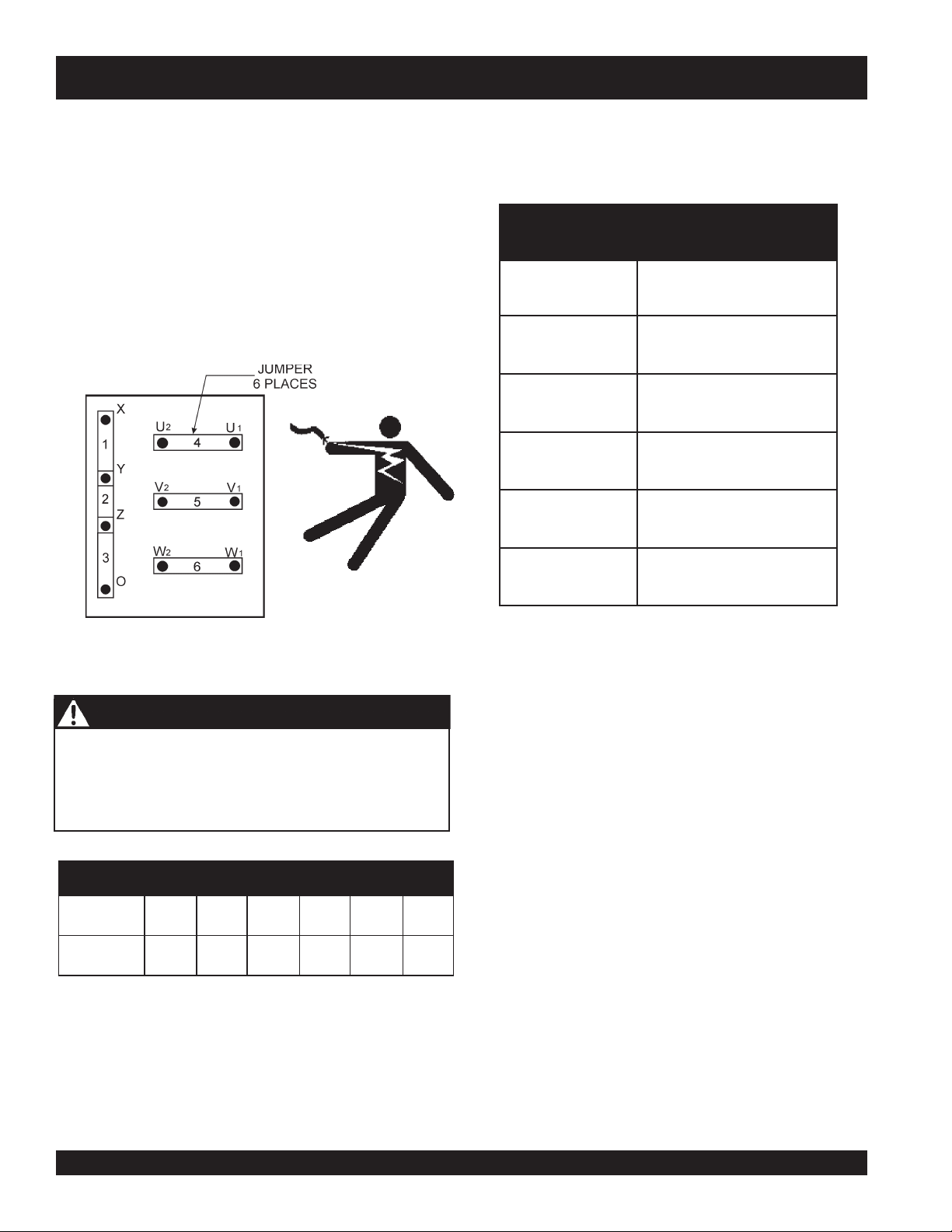
Generator Output Voltages
A wide range of voltages are available to supply voltage for
many different applications. Voltages are selected by applying jumpers (6) to the
voltage change-over board
(Figure 15).
Maximum Amps
Table 8 shows the
vide. DO NOT exceed the maximum amps as listed.
To obtain some of the voltages as listed in Table 7 (see
below) will require a fine adjustment using the
lator
(VR)
control knob
located on the control panel.
voltage regu-
Voltage Change-Over Board
The
voltage change-over board
(Figure 14) is located on
the control box, behind the generator control panel. This
board has been provided for ease of voltage selection.
maximum
:ledoMVSS006ACD
detaR
egatloV
tloV
tloV
esahPeerhT
tloV042
eerhT
esahP
tloV084
amps the generator can pro-
spmAmumixaM.8elbaT
spmAmumixaM
021esahPelgniS
042esahPelgniS
)eriw4(spma3.3331
)eriw4(spma7.666
spma4.3441
spma7.127
Figure 14. Voltage Change-Over Board
240V Configuration
DANGER - CHANGING JUMPER PLATES
NEVER attempt to place jumper plates on the voltage
change-over board while the generator is in operation. There
exists the possibility of electrocution, electrical shock or
burn, which can cause severe bodily harm or even death!
segatloVelbaliavArotareneG.7elbaT
V802V022V042V614V044V084
esahP-eerhT
V021V721V931V042V452V772
esahP-elgniS
PAGE 30 — DCA-600SSV — OPERATION AND PARTS MANUAL — REV. #0 (07/13/09)
Page 31

DCA-600SSV — GENERATOR OUTPUTS/GAUGE READING
How to Read the AC Ammeter and AC Voltage Gauges.
The AC ammeter and AC voltmeter gauges are controlled
by the Ac ammeter and AC voltmeter change-over switches.
Both of these switches are located on the generator control
panel and DO NOT effect the generator output. They are
provided to help observe how much power is being supplied,
AC Ammeter Gauge Reading
Place the
in the U position and observe the current reading (load drain)
on the U terminal as indicated in the
(Figure 19). This process can be repeated for terminals V
and W.
produced at the UVWO terminals lugs.
Before taking a reading from either gauge, configure the volt-
age change-over board which produces the desired
outputvoltage. When the voltage change-over board is
jumpered for 3Ø, 240V operation (See Figure 15).
Figure 18. AC Ammeter
Change-Over Switch
NOTE
Figure 15. Voltage Change-Over Board
240V/3Ø Configuration
AC Ammeter Change-Over Switch
AC Ammeter Gauge
40
20
0
A
Figure 19. AC Ammeter
(Amp reading on U lug)
The
ammeter
gauges will only show a reading
when the
Lugs
are connected to a load
and in use.
and
Output Terminal
(Figure 18)
60
75
voltmeter
AC Voltmeter Gauge Reading
Place the
AC Voltmeter Change-Over Switch
(Figure 16)
in the W-U position and observe the phase to phase voltage
reading between the W and U terminals as indicated in the
AC Voltmeter Gauge
Figure 16. AC Voltmeter
Change-Over Switch
(Figure 17).
Figure 17 AC Voltmeter
Gauge
(Volt reading on W-U Lug)
DCA-600SSV — OPERATION AND PARTS MANUAL — REV. #0 (07/13/09) — PAGE 31
Page 32

DCA-600SSV — OUTPUT TERMINAL PANEL CONNECTIONS
UVWO Terminal Output Voltages
Various output voltages can be obtained using the UVWO
output terminal lugs. The voltages at the terminals are dependent on the placement of the jumpers plates (6) on the
Voltage Change-Over Board
Voltage Regulator Control Knob
Remember the voltage change-over board determines the
range
of the output voltage and can be configured in two
different positions that provide 6 different output voltages at
the UVWO output terminals. The generator is shipped from
the factory in the 240V configuration. The voltage regulator
(VR) allows the user to increase or decrease the selected
voltage.
3Ø-240V UVWO Terminal Output Voltages
1. Jumper the voltage change-over board for 240V operation
as shown in Figure 20.
and the adjustment of the
.
1Ø-240V UVWO Terminal Output Voltages
1. Make sure the voltage change-over board is jumpered
for 240V operation as shown in Figure 20 .
2. Connect the load wires to the UVWO terminals as shown
in Figure 23.
Figure 22. Voltage Regulator Knob
Figure 20. Voltage Change-Over Board
240V Configuration
2. Connect the load wires to the UVWO terminals as shown
in Figure 21.
1Ø-139V UVWO Terminal Output Voltages
1. Make sure the voltage change-over board is jumpered
for 240V operation as shown in Figure 20.
2. Connect the load wires to the UVWO terminals as shown
in Figure 24.
Figure 21. UVWO Terminal Lugs
3Ø-240V Connections
3. Turn the voltage regulator knob (Figure 23) clockwise to
increase voltage output, turn counterclockwise to
decrease voltage output. Use voltage regulator
adjustment knob whenever fine tuning of the output
voltage is required
Figure 23. UVWO Terminal Lugs
1Ø-240V Connections
Figure 24. UVWO Terminal Lugs
1Ø-120V Connections
PAGE 32 — DCA-600SSV — OPERATION AND PARTS MANUAL — REV. #0 (07/13/09)
Page 33

DCA-600SSV — OUTPUT TERMINAL PANEL CONNECTIONS
3Ø-480V UVWO Terminal Output Voltages
1. Jumper the voltage change-over board for 480V operation
as shown in Figure 25. This configuration uses 6 jumper
plates in 3 different positions. Remember there are 2
jumper plates at every position. Every jumper plate
must
1Ø-480V UVWO Terminal Output Voltages
1. Make sure the voltage change-over board is jumpered
for 480V operation as shown in Figure 25.
2. Connect the load wires to the UVWO terminals as shown
in Figure 27.
be used.
Figure 265 Voltage Change-Over Board
480V Configuration
2. Connect the load wires to the UVWO terminals as shown
in Figure 26.
1Ø-277V UVWO Terminal Output Voltages
1. Make sure the voltage change-over board is jumpered
for 480V operation as shown in Figure 25.
Figure 27. UVWO Terminal Lugs
1Ø-480V Connections
Figure 26. UVWO Terminal Lugs
3Ø-480V Connections
ALWAYS make sure that the
NOTE
connections to the UVWO
terminals are
The possibility of arcing exists,
that could cause a fire.
secure
and tight.
DANGER - UVWO OUTPUT TERMINALS
NEVER attempt to connect a load to the UVWO output
terminals while the generato
exists of serious injury, electrical shock, electrocution even
death.
r
is operating. The possibility
2. Connect the load wires to the UVWO terminals as shown
in Figure 28.
Figure 28. UVWO Terminal Lugs
1Ø-277V Connections
DCA-600SSV — OPERATION AND PARTS MANUAL — REV. #0 (07/13/09) — PAGE 33
Page 34

DCA-600SSV — SETUP
Circuit Breakers
To protect the generator from an overload, a 3-pole, 1600
main
amp,
circuit breaker is provided to protect the UVWO
output terminals from overload. In addition two single-pole,
20 amp
GFCI receptacles from overload. Three 50 amp
GFCI
circuit breakers are provided to protect the
load
circuit
breakers have also been provided to protect the auxiliary
receptacles from overload. Make sure to switch
ALL
circuit
Fuel Check
DANGER - EXPLOSION/FIRE HAZARDS
Fuel spillage on a
If fuel spillage occurs, wipe up the spilled fuel completely
to prevent fire hazards. NEVER smoke around or near the
generator.
breakers to the "OFF" position prior to starting the engine.
Lubrication Oil
Fill the engine crankcase with lubricating oil through the filler
hole, but DO NOT overfill. Make sure the generator is level.
Also verify that the oil level is maintained between the two
REFILLING THE FUEL SYSTEM
notches (Figure 29) on the dipstick. See Table 9 for proper
selection of engine oil.
CAUTION - REFUELING THE GENERATOR
ONLY properly trained personel who have read and
understand this section should refill the fuel tank system.
hot
engine can cause a
fire
or
explosion
.
The DCA600SSV series generators may (if equipped with a
trailer or skid) have a
Figure 29. Engine Oil Dipstick
When checking the engine oil, be sure to check if the oil is
clean. If the oil is not clean, drain the oil by removing the oil
drain plug, and refill with the specified amount of oil as outlined
in the Volvo Engine Owner's Manual. Oil should be warm
before draining.
Other types of motor oils may be substituted if they meet
the following requirements:
API Service Classification CH-4
API Service Classification CG-4
API Service Classification CF-4
ACEA Specification E3
ACEA Specification E2
which consists of an
trailer mounted
can be equipped with a
The skid type fuel system does not use the internal generator
fuel tank.
Use the instructions in this section that applies to your type
of fuel tank system.
ALWAYS
fuel.
DO NOT fill the fuel tanks beyond their capacities.
Pay attention to the fuel tank capacity when replenishing
fuel. The fuel tank cap must be closed tightly after filling.
Handle fuel in a safety container. If the container does not
have a spout, use a funnel. Wipe up any spilled fuel
immediately.
liOrotoMdednemmoceR.9elbaT
egnaRerutarepmeTliOepyT
o
41
05~FoF
o
o
01-(
01~C
)C
o
23
o
0(
evobadnaF
evobadnaC
W01EAS
03-W01EASro03EAS
double fuel tank system
internal
generator fuel tank, and a
(Figure 30),
fuel tank. It is also possible the generator
skid mounted
fill the fuel tank with clean and fresh
fuel tank (Figure 32).
#2 diesel
Figure 30. Double Fuel Tank System
PAGE 34 — DCA-600SSV — OPERATION AND PARTS MANUAL — REV. #0 (07/13/09)
Page 35

DCA-600SSV — SETUP
CAUTION - TRAILER FUEL TANK
Figure 31. Skid Type Fuel Tank System
Refueling Procedure:
WARNING - RESPIRATORY HAZARDS
Diesel fuel and its vapors are dangerous
to your health and the surrounding
environment. Avoid skin contact and/or
inhaling fumes.
1. Level Tanks – make sure fuel cells are level with the
ground. Failure to do so will cause fuel to spill from the
tank before reaching full capacity. See Figure 32.
CAUTION - REFUELING THE GENERATOR
ALWAYS!
fill trailer tank
first
with
#2 diesel fuel
filling secondary internal tank.
DIESEL
FUEL
DIESEL
FUEL
INTERNAL
SECONDARY
TANK
TRAILER
TANK
INTERNAL
FUEL TANK
SIGHT GAUGE
Full
3/4
1/2
1/4
Empty
Full
3/4
1/2
1/4
Empty
CORRECT
Figure 33. Fuel Tank Filling Order
, before
INCORRECT
ALWAYS! FILL THE
TRAILER FUEL TANK
, BEFORE FILLING
FIRST
INTERNAL FUEL TANK
ALWAYS
place trailer on firm level ground before refueling
to prevent spilling and maximize the amount of fuel that
can be pumped into the tank.
Figure 32. Only Fill on Level Ground
2. Trailer Fuel Tank First – The trailer fuel tank is the
primary fuel tank and holds a larger capacity of fuel.
The fuel in the trailer will be filtered and sent to the
engine.
ALWAYS
fill trailer fuel tank (Figure 33) first.
DCA-600SSV — OPERATION AND PARTS MANUAL — REV. #0 (07/13/09) — PAGE 35
NOTE
NOTE
ONLY! use
#2 diesel fuel
when
refueling.
Fuel from the secondary inner
tank will eventually drain into the
primary trailer tank.
Page 36

DCA-600SSV — SETUP
3. NEVER overfill trailer fuel tank – It is important to
read the trailer fuel gauge when filling trailer fuel tank.
DO NOT wait for fuel to rise in filler neck. See Figure 34.
Figure 34. Full Trailer Tank
CAUTION - REFUELING THE GENERATOR
DO NOT OVER-FILL fuel system. Leave room for fuel
expansion . Fuel expands when heated (Figure 36).
4. Once the trailer tank is full, the
secondary inner tank
can be filled (See Figure 35). Notice how the trailer
filler tube level rises when the internal tank is filled.
5. Figure 36 below reflects a full fuel system.
Figure 36. Full Fuel System
Fuel from the engine return line will drain into the secondary
6.
internal fuel tank. This fuel will eventually drain into the
primary trailer tank in order to return to the engine.
CAUTION - REFUELING SECONDARY FUEL TANK
It is recommended to only fill the internal secondary take to 3/
4 full in order to allow for fuel return, fuel expansion, and to
avoid spillage. See Figure 37 for fuel expansion.
Figure 35. Filling Secondary Internal Fuel Tank
PAGE 36 — DCA-600SSV — OPERATION AND PARTS MANUAL — REV. #0 (07/13/09)
Figure 37. Fuel Expansion
Page 37

Coolant (Ethylane Glycol [Green] / Water — 50/50 mix)
DCA-600SSV— SETUP
Use only drinkable tap water. If hard water or water with
many impurities is used, the inside of the engine and radiator
NOTE
may become coated with deposits and cooling efficiency
will be reduced.
An anticorrosion additive added to the water will help prevent
deposits and corrosion in the cooling system. See the engine
manual for further details.
Cleaning the Radiator
The engine may overheat if the radiator fins become
overloaded with dust or debris. Periodically clean the radiator
fins with compressed air. Cleaning inside the machine is
WARNING - BURN HAZARDS
dangerous, so clean only with the engine turned off and the
negative
If adding coolant/antifreeze mix to the
radiator, DO NOT remove the radiator cap
until the unit has completely cooled. The
possibility of
hot!
coolant exists which
can cause severe burns.
Air Cleaner
Periodic cleaning/replacement is necessary. Inspect it in
accordance with the Volvo Engine Owner's Manual.
Fan Belt Tension
A slack fan belt may contribute to overheating, or to
Day-to-day addition of coolant is done from the recovery
tank. When adding coolant to the radiator, DO NOT remove
the radiator cap until the unit has completely cooled. See
insufficient charging of the battery. Inspect the fan belt for
damage and wear and adjust it in accordance with the Volvo
Engine Owner's Manual.
Table 10 for engine and radiator, coolant capacities. Make
sure the coolant level in the recovery tank is always between
the "H" and the "L" markings.
The fan belt tension is proper if the fan belt bends 10 to 15
mm (Figure 38) when depressed with the thumb as shown
below.
When the antifreeze is mixed with
water, the antifreeze mixing ratio
must be
less than 50%.
battery terminal disconnected.
yticapaCtnalooC.01elbaT
rotaidaRdnaenignE)sretiL0.39(.laG6.42
knaTevreseR)sretiL9.1(strauQ2
Operation Freezing Weather
When operating in freezing weather, be certain the proper
amount of antifreeze (Table 11) has been added.
serutarepmeTgnitarepOezeerF-itnA.11elbaT
tnioPgnizeerFtnioPgnilioB
%loV
ezeerF-itnA
C°F°C°F°
0442-21-601222
0573-43-80
1622
Figure 38. Fan Belt Tension
CAUTION - ROTATING PARTS
NEVER place hands near
the belts or fan while the
generator set is running.
DCA-600SSV — OPERATION AND PARTS MANUAL — REV. #0 (07/13/09) — PAGE 37
Page 38

DCA-600SSV— SETUP
Battery
This unit is of negative ground DO NOT connect in reverse.
Always maintain battery fluid level between the specified
marks. Battery life will be shortened, if the fluid level are
not properly maintained. Add only distilled water when
replenishment is necessary.
DO NOT over fill. Check to see whether the battery cables
are loose. Poor contact may result in poor starting or
malfunctions.
Coating the terminals with an approved battery terminal
treatment compound. Replace battery with only
recommended type battery.
The battery is sufficiently charged if the specific gravity of
the battery fluid is 1.28 (at 68° F). If the specific gravity
should fall to 1.245 or lower, it indicates that the battery is
dead and needs to be recharged or replaced.
Battery Cable Installation
ALWAYS be sure the battery cables (Figure 39) are properly
connected to the battery terminals as shown below. The
RED
cable is connected to the positive terminal of the battery,
and the BLACK cable is connected to the negative terminal
of the battery.
Always
keep the terminals firmly tightened.
When connecting battery do the following:
1. NEVER connect the battery cables to the battery
terminals when the
Heat, RUN, or START position. ALWAYS make sure
that the ignition switch is in the STOP position when
connecting the battery.
2. Place a small amount of battery terminal treatment
compound around both battery terminals. This will ensure
a good connection and will help prevent corrosion around
the battery terminals.
NOTE
CAUTION - BATTERY SERVICING SAFETY
Inadequate battery connections may cause poor starting
of the generator, and create other malfunctions.
ignition
switch is in either the Pre-
If the battery cable is connected
incorrectly, electrical damage to the
generator will occur. Pay close
attention to the polarity of the
battery when connecting the
battery.
CAUTION - BATTERY SERVICING SAFETY
ALWAYS
reconnect negative terminal LAST.
disconnect the negative terminal FIRST and
Figure 39. Battery Connections
Alternator
The polarity of the alternator is negative grounding type.
When an inverted circuit connection takes place, the circuit
will be in short circuit instantaneously resulting the alternator
failure.
DO NOT put water directly on the alternator. Entry of water
into the alternator leads an electrolyte corrosion causing an
alternator failure.
Before charging the battery with an external electric source,
be sure to disconnect the battery cables.
Wiring
Inspect the entire generator for bad or worn electrical wiring
or connections. If any wiring or connections are exposed
(insulation missing) replace wiring immediately.
Piping and Hose Connection
Inspect all piping, oil hose, and fuel hose connections for
wear and tightness. Tighten all hose clamps and check hoses
for leaks.
If any hose (
immediately
fuel
.
or
oil
) lines are defective replace them
PAGE 38 — DCA-600SSV — OPERATION AND PARTS MANUAL — REV. #0 (07/13/09)
Page 39

DCA-600SSV — GEN. START-UP PROCEDURE (MANUAL)
BEFORE STARTING
3. Place the
“OFF” position prior to starting the engine.
CAUTION - LETHAL EXHAUST HAZARD
The engine's exhaust contains harmful emissions.
ALWAYS have adequate ventilation when operating
.
Direct exhaust away from nearby personnel.
If applicable perform the following:
■
Apply commercial power to the internal battery charger
receptacle (to ensure good starting) via commercial power.
An external power cord will be required. This capability is an
option
.
■
Apply commercial power to the jacket water heater
receptacle (not necessary for warm climates) via commercial
power. An external power cord will be required. This capability
is an
option
.
Generator and Control Panel
4. Connect the load to the
WARNING - STARTING THE GENERATOR
NEVER!
or
manually start the engine with the
auxiliary
circuit breakers in the ON (closed) position.
main, GFCI
receptacles
connection points can be found on the output terminal
panel. To gain access to the UVWO terminals or other
power receptacles, unlock the access cover and lift the
door.
G.F.C.I.
Figure 42. GFCI and Auxiliary
Circuit Breakers (OFF)
and
aux.
circuit
breakers (Figure 42) in the
UVWO
terminals or
as shown in Figure 43. These load
auxiliary
1. Press the
Figure 40. Main Circuit Breaker OFF Switch
2. Verify that the
main
main
circuit
breaker “OFF” switch (Figure 40).
circuit
breaker “OFF” lamp (Figure 41)
is lit (ON).
Figure 41. Main Circuit Breaker OFF Lamp
5. Tighten the UVWO terminal nuts securely to prevent
load wires from slipping out.
Figure 43. Load Connections
6. Close all engine enclosure doors (Figure 44).
INCORRECTCORRECT
Figure 44. Engine Enclosure Doors
DCA-600SSV — OPERATION AND PARTS MANUAL — REV. #0 (07/13/09) — PAGE 39
Page 40

DCA-600SSV— GENERATOR START-UP PROCEDURE (MANUAL)
7. Set the
position.
battery ON/OFF switch
Figure 45. Battery ON/OFF Switch
(Figure 45) to the “ON”
12. Verify that the "Engine Running" status LED on the MPEC
unit (Figure 50) is "ON" (lit) after the engine has been started.
8. Press and hold the engine preheat button (Figure 46)
until the preheat lamp is lit (ON).
Pre-Heat
Button
Pre-Heat
Lamp
Figure 50. Engine Running LED (ON)
13. The generator's frequency meter (Figure 51) should be
displaying the 60 cycle output frequency in HERTZ.
Figure 46. Pre-Heat Button/ Lamp
9. Place the engine speed switch in the “
LOW
” position
(Figure 47).
Figure 47. Engine Speed Switch (Low)
10. Place the Auto-Off/Reset-Manual switch in the “
Manual”
position to start the engine (Figure 48). Once the engine
starts, let the engine run for 1-2 minutes. Listen for any
abnormal noises.
Figure 48. Auto-Off/Reset-Manual Switch
11. Once the engine is warm and the engine is running
properly, place the engine speed switch in the “
HIGH
”
position (Figure 49).
Figure 49. Engine Speed Switch (High)
Figure 51. Frequency Meter (Hz)
14. The generator's AC-voltmeter (Figure 52) will display the
generator’s output in VOLTS.
Figure 52. AC Voltmeter
15. If the voltage is not within the specified tolerance, use
the voltage adjustment control knob (Figure 53) to
increase or decrease the desired voltage.
Figure 53. Voltage Adjust Control Knob
PAGE 40 — DCA-600SSV — OPERATION AND PARTS MANUAL — REV. #0 (07/13/09)
Page 41

DCA-600SSV— GENERATOR START-UP PROCEDURE (MANUAL)
16. The ammeter (Figure 54) will indicate zero amps with no
20. Press the
load applied. When a load is applied, the ammeter will
indicate the amount of current that the load is drawing
from the generator.
Figure 58. Main Circuit Breaker ON Switch
Figure 54. Ammeter (No Load)
17. The engine oil pressure gauge (Figure 55) will indicate
21. Verify that the
is lit (ON).
the oil pressure (kg/ cm2) of the engine. Under normal
operating conditions the oil pressure is approximately
4
8
kg/cm2
0
ENGINE OIL PRESSURE
22. Place the
Figure 55. Oil Pressure Gauge
“OFF” position prior to starting the engine.
main
circuit
breaker “ON” switch (Figure 58).
main
circuit
breaker “ON” lamp (Figure 59)
Figure 59. Main Circuit Breaker ON Lamp
G.F.C.I.
and
aux.
circuit
breakers (Figure 60) in the
18. The
coolant temperature gauge
(Figure 56) will indicate
the coolant temperature. Under normal operating
conditions the coolant temperature should be between
167 and 203 degrees Fahrenheit (
WATER
Figure 56. Coolant Temperature Gauge
19. The
tachometer gauge
(Figure 57) will indicate the
Green Zone
TE
MP
).
speed of the engine when the generator is operating.
Under normal operating conditions this speed is
approximately 1800 RPM’s.
Figure 60. GFCI and Auxiliary
Circuit Breakers (ON)
Figure 57. Engine Tachometer Gauge
DCA-600SSV — OPERATION AND PARTS MANUAL — REV. #0 (07/13/09) — PAGE 41
Page 42

DCA-600SSV — GENERATOR START-UP PROCEDURE (AUTO MODE)
23. Observe the generator's ammeter (Figure 61) and verify
it reads the anticipated amount of current with respect
to the load. The ammeter will only display a current
reading if a load is in use.
When starting generator in AUTO mode use the "
Start-up" procedure except where noted (see below).
1. Perform steps 1 through 4 in the
(page 38) as outlined in the
2. Set the
position.
Figure 61. Ammeter (Load)
24. The generator will run until manually stopped or an
abnormal condition occurs.
DANGER - ELECTRICAL SYSTEM HAZARDS
NOTE
Before connecting this generator to any
building’s electrical system, a
electrician
(transfer) switch
must install an
. Serious damage to the
building’s electrical system may occur
licensed
isolation
3. Set the engine speed switch (Figure 63) to the “High”
position.
without this transfer switch.
Before Starting
Manual Starting Procedure
battery ON/OFF switch
Figure 62. Battery ON/OFF Switch
When the generator is set in the “
AUTO ” mode, the generator will
automatically start
commercial power falling below a
prescribed level by means of a
contact closure that is generated
automatically by a transfer switch.
(Figure 62) to the “ON”
in the event of
Manual
section
.
CAUTION - BACKUP GENERATOR USE
When connecting the generator to a isolation (transfer)
Figure 63. Engine Speed Switch (High)
switch, ALWAYS have power applied to the generator's
internal battery charger. This will ensure that the engine
will not fail due to a dead battery.
4. Place the Off/Manual/Auto switch (Figure 64) on the
MPEC unit to the AUTO position.
WARNING - AUTO MODE MAINTENANCE
When running the generator in the AUTO mode, remember
the generator can start up at any time without warning.
NEVER attempt to perform any maintenance when the
Figure 64. Off/Manual Auto Switch (AUTO)
generator is in the auto mode.
5. Press the circuit breaker
CAUTION - ENGINE SPEED SWITCH
The
Engine Speed Switch
position when running in the
must be set to the "High"
Auto-Start
mode. Failing to
6. Verify that the circuit breaker on lamp (Figure 59) is lit.
7. Continue operating the generator as outlined in the
Manual Start-up
set the switch in the proper position can result in damage
to your generator when it turns on.
ON Switch
(Figure 58).
procedure (start at step 10).
PAGE 42 — DCA-600SSV — OPERATION AND PARTS MANUAL — REV. #0 (07/13/09)
Page 43

DCA-600SSV — GENERATOR SHUT-DOWN PROCEDURE
EMERGENCY
STOP
PUSH
TO STOP
WARNING -
NEVER stop the engine suddenly except in an emergency.
SHUTTING DOWN THE GENERATOR
1. PUSH inward the emergency stop button located on the
engine operating panel
generator in the event of an emergency.
Normal Shutdown Procedure
To shutdown the generator use the following procedure:
1. Place both the GFCI and AUX circuit breakers as shown
in Figure 42 to the OFF position.
Emergency Shutdown Procedure
2. Place the engine speed switch (Figure 65) in the
“LOW ” (down) position.
Figure 67. Emergency Stop Button
Figure 65. Engine Speed Switch (Low)
3. Let the engine cool by running it at low speed for 3-5
minutes with no load applied.
4. Place the
MPEC Control Switch
(Figure 66) in the
OFF/RESET position.
(Figure 67) to turn off the
Figure 66. MPEC Control Switch (Off/Reset)
5. Press the
6. Verify that the
main
main
circuit
breaker “OFF” switch (Figure 40).
circuit
breaker “OFF” lamp (Figure 41)
is lit (ON).
7. Verify that the
all
status LED on the MPEC display
are OFF (not lit).
8. Remove all loads from the generator.
9. Inspect entire generator for any damage or loosening of
components that may have occured during operation.
DCA-600SSV — OPERATION AND PARTS MANUAL — REV. #0 (07/13/09) — PAGE 43
Page 44

DCA-600SSV — MAINTENANCE
ECNANETNIAM/NOITCEPSNI.41ELBAT
sleveLdiulFenignEkcehC X
renaelCriAkcehC X
leveLdicAyrettaBkcehC X
noitidnoCtleBnaFkcehC X
skaeLrofkcehC X
straPfogninesooLrofkcehC X
1
*retliFdnaliOenignEecalpeR
ENIGNE
ROTARENEG
retliFriAnaelC X
lwoBrotarepeSretaW/retliFleuFkcehC X
edistuOdnaedisnI,tinUnaelC X
retliFleuFegnahC X
2
*leveLnoitcetorPtnalooCkcehCdnarotaidaRnaelC
3
*tnemelEretliFriAecalpeR
4
*spmalCdnasesoHllakcehC
knaTleuFfoedisnInaelC X
smhoM3revOecnatsiseRnoitalusnIerusaeM X
gniraeBtroppuSraeRrotoRkcehC X
.lioro/d
naerutsiomtcellocdluoctahtspidrosgason
srH01
YLIAD
.ylnoemittsrif,sruoh001taretliffnalioenigneecalpeR1*
srH052 srH005 srH0001
X
X
X
.tnaloocenigneehtegrahcerot")S'ACS(sevitaddAtnalooClatnemelppuS"ddA2*
X
H.ni52(mm526fomuccavaswohsrotacidninoitcirtsernehwtnemeleretlifriayramirpecalpeR3*
2
.)0
htiw,toofrephcni2/1atsaeltasiesohybolbehtfoepolsehttahterusne,decalperebotsdeenesohybwolbfI4*
General Inspection
Prior to each use, the generator should be cleaned and
inspected for deficiencies. Check for loose, missing or
damaged nuts, bolts or other fasteners. Also check for fuel,
oil, and coolant leaks. Use Table 14 as a general maintenance
guideline Engine Side (Refer to the Engine Instruction
Manual)
Air Cleaner
Every 250 hours: Remove air cleaner element (Figure 68)
and clean the heavy duty paper element with light spray of
compressed air. Replace the air cleaner as needed.
Air Cleaner with Dust Indicator
This indicator (Figure 65) is attached to the air cleaner. When
NOTE
the air cleaner element is clogged, air intake restriction
becomes greater and the dust indicator signal shows RED
meaning the element needs changing or service. After
changing the air element, press the dust indicator button to
reset the indicator.
PAGE 44 — DCA-600SSV — OPERATION AND PARTS MANUAL — REV. #0 (07/13/09)
Figure 68. Air Cleaner/Indicator
The air filter should not be
changed until the indicator reads
“RED”. Dispose of old air filter it
may not be cleaned or reused.
Page 45

DCA-600SSV — MAINTENANCE
Service Daily
If the engine is operating in very
conditions, a clogged air cleaner will result. This can lead to
a loss of power, excessive carbon buildup in the combustion
chamber and high fuel consumption. Change air cleaner
more
frequently
Fuel Addition
Add diesel fuel (the grade may vary according to season
and locations).
Removing Water from the Fuel Tank
After prolonged use, water and other impurities accumulate
in the bottom of the tank. Occasionally inspect the fuel
tank for water contamination and drain the contents if
required.
During cold weather, the more empty volume inside the
tank, the easier it is for water to condense. This can be
reduced by keeping the tank full with diesel fuel.
Cleaning Inside the Fuel Tank
Drain the fuel inside the fuel tank completely. Using a spray
washer (Figure 69) wash out any deposits or debris that have
accumulated inside the fuel tank.
if these conditions exists.
dusty
or
dry grass
Fuel Tank Inspection
In addition to cleaning the fuel tank, the following components
should be inspected for wear:
■■
Rubber Suspension – look for signs of wear or
■
■■
deformity due to contact with oil. Replace the rubber
suspension if necessary.
■■
■
Fuel Hoses – inspect nylon and rubber hoses for signs
■■
of wear, deteration and hardning.
■■
■
Fuel Tank Lining – inspect the fuel tank lining for signs
■■
of excessive amounts of oil or other foreign matter.
Cleaning the Fuel Strainer
Clean the fuel strainer if it contains dust or water. Remove
dust or water in the strainer cap and wash it in gasoline.
Securely fasten the fuel strainer cap so that fuel will not
leak. Check the fuel strainer every 200 hours of operation or
once a month.
Replacing Fuel Filter
Replace the fuel filter cartridge with new one every 500
hours or so.
Loosen the drain plug at the lower top of the fuel filter.
Drain the fuel in the fuel body together with the mixed
water. DO NOT spill the fuel during disassembly.
Figure 69. Fuel Tank Cleaning
Vent any air
DCA-600SSV — OPERATION AND PARTS MANUAL — REV. #0 (07/13/09) — PAGE 45
Page 46

DCA-600SSV — MAINTENANCE
Air Removal
If air enters the fuel injection system of a diesel engine,
starting becomes impossible. After running out of fuel, or
after disassembling the fuel system, bleed the system
according to the following procedure. See the
Manual
To restart after running out of fuel, turn the switch to the
“ON” position for 15-30 seconds. Try again, if needed. This
unit is equipped with an automatic air bleeding system.
Check Oil Level
Check the crankcase oil level prior to each use, or when the
fuel tank is filled. Insufficient oil may cause severe damage
to the engine. Make sure the generator is level. The oil level
must be between the two notches on the dipstick as shown
in Figure 29.
Replacing Oil Filter
for details.
Remove the old oil filter.
Apply a film of oil to the gasket on the new oil filter.
Install the new oil filter.
VOLVO Engine
WARNING - BURN HAZARDS
Allow engine to
radiator. Flushing the radiator while hot
could cause serious burns from water or
steam.
Radiator Cleaning
The radiator (Figure 70) should be sprayed (cleaned)
with a high pressure washer when excessive amouts of
dirt and debris have accumulated on the cooling fins or
tube. When using a high pressure washer, stand at least
5 feet (1.5 meters) away from the radiator to prevent
damage to the fins and tube.
cool
when flushing out
After the oil cartridge has been replaced, the engine oil
will drop slightly. Run the engine for a while and check
for leaks before adding more oil if needed. Clean
excessive oil from engine.
Flushing Out Radiator and Replacing Coolant
Open both cocks located at the crankcase side and at
the lower part of the radiator and drain coolant. Open the
radiator cap while draining. Remove the overflow tank
and drain.
Check hoses for softening and kinks. Check clamps for
signs of leakage.
Tighten both cocks and replace the overflow tank.
Replace with coolant as recommended by the engine
manufaturer.
Close radiator cap tightly.
Flush the radiator by running clean tap water through
radiator until signs of rust and dirt are removed. DO NOT
clean radiator core with any objects, such as a
screwdriver.
Figure 70. Air Cleaner/Indicator
Generator Storage
For longe term storage of the generator the following is
recommended:
Fill the fuel tank completely. Treat with a fuel stabilizer
if necessary.
Completely drain the oil from the crankcase and refill if
necessary with fresh oil.
Clean the entire generator, internal and external.
Cover the generating set and store in a clean, dry place.
Disconnect the battery.
Make sure engine coolant is at proper level.
If generator is mounted on a trailer, jack trailer up and
place on blocks so tires do not touch the ground or block
and completely remove the tires.
PAGE 46 — DCA-600SSV — OPERATION AND PARTS MANUAL — REV. #0 (07/13/09)
Page 47

DCA-600SSV — MAINTENANCE
Jacket Water Heater and Internal Battery Charger
120 VAC Input Receptacles (OPTIONAL)
This generator can be optionally equipped with two 120 VAC,
20 amp input receptacles located on the output terminal
panel.
The purpose of these receptacles is to provide power via
commercial power to the
battery charger
These receptacles will ONLY function when commercial
power has been supplied to them (Figure 71). To apply
commercial power to these receptacles, a power cord of
adequate size will be required (See Table 6).
When using the generator in
to apply power to jacket water heater. However, if the
generator will be used in
idea to apply power to the jacket water heater at all times. To
apply power to the jacket water heater simply apply power to
the jacket water heater receptacle via commercial power
using an power cord of adequate size.
.
jacket water heater
hot
climates there is no reason
cold
climates it is always a good
and
internal
If the generator will be used daily, the battery should normally
not require charging. If the generator will be idle (not used)
for long periods of time, apply power to the battery charger
receptacle via commercial power using an power cord of
adequate size.
NOTE
To ensure adequate starting
capability, always have power
applied to the generator's
internal battery charger
.
Figure 71. Battery Charger &
Jacket Water Heater Power Connections
DCA-600SSV — OPERATION AND PARTS MANUAL — REV. #0 (07/13/09) — PAGE 47
Page 48

DCA-600SSV —TRAILER BRAKES MAINTENANCE
Electric Brakes
Electrically actuated brakes (Figure 72) are similar to
hydraulic brakes. The basic difference is that hydraulic
brakes are actuated by an electromagnet. Listed below are
some of the advantages that electric brakes have over
hydraulic brakes:
Brake system can be manually adjusted to provide the
corrected braking capability for varying road and load
conditions.
Brake system can be modulated to provide more or less
braking force, thus easing the brake load on the towing
vehicle.
Brake system has very little lag time between the time
the vehicle’s brakes are actuated and the trailer’s brakes
are actuated.
Brake system can provide an independent emergency
brake system.
Remember in order to properly synchronize the tow vehicle’s
braking to the trailer’s braking, can only be accomplished by
road testing. Brake lockup, grabbiness or harshness is due
to lack of synchronization between the tow vehicle and the
trailer being towed or under-adjusted brakes.
Before any brake synchronizations adjustments can be
made, the trailer brakes should be burnished-in by applying
the brakes 20-30 times with approximately a 20 m.p.h. decrease in speed, e.g. 40 m.p.h. to 20 m.p.h. Allow ample
time for brakes to cool between application. This allows the
brake shoes to slightly be seated into the brake drum surface.
Figure 72. displays the major electric brake components that
will require inspection and maintenance. Please inspect
these components as required. See Table 15. Electric Brake
Troubleshooting.
Magnets For All Electric Brakes
To make certain an electrically-operated braking system will
function properly, you must have your dealer inspect the
magnets at least once a year, or each 12,000 miles. See
the brake manual for wear and current inspection instructions.
Brake Controller
The electric brake controller is part of the tow vehicle and is
essential in the operation of the electric brakes on the trailer.
The brake controller is not the same as the safety breakaway
brake system that may be equipped on the trailer.
Brake Drums (or discs), Linings, and Hoses
Brake drums or discs must not have cracks longer than one
half the width of the friction area. Linings must not be loose,
soaked with oil or grease or be dangerously thin. Mechanical
parts must be in place, not broken or missing. Check that
all air hoses connected to the brake chambers are not worn
or cut due to rubbing.
Air Leaks
Always check for brake air leaks before towing the trailer.
NEVER tow the trailer with an brake air leak problem. The
possibility exists of brake failure.
Symptom Possible Cause Solution
No Brakes or Intermittent
Brakes
Weak Brakes or Brakes Pull to
One Side
Locking Brakes Brake components loose, bent or broken? Replace components.
Noisy Brakes System lubricated? Lubricate.
Dragging Brakes Bearings of the wheel adjusted? Adjust.
Figure 72. Electric Brake Components
Table 15. Electric Brake Troubleshooting
Any open circuits or broken wires? Find and correct.
Any short circuits? Find and correct.
Faulty controller? Test and correct.
Any loose connections? Find and repair.
Ground wire secure? Find and secure.
Grease or oil on magnets or linings? Clean or replace.
Connections corroded? Clean and correct cause
Brake drums scored or grooved? Machine or replace.
Brakes synchronized? Correct.
Brake drums out-of-round? Replace.
Brake components correct? Replace and correct.
of corrosion.
PAGE 48 — DCA-600SSV — OPERATION AND PARTS MANUAL — REV. #0 (07/13/09)
Page 49

DCA-600SSV —TRAILER MAINTENANCE
Tires/Wheels/Lug Nuts
Tires and wheels are a very important and critical
components of the trailer. When specifying or replacing the
trailer wheels it is important the wheels, tires, and axle are
properly matched.
CAUTION - EYESIGHT HAZARD
ALWAYS
removing or installing force fitted parts.
Failure to comply may result in serious
injury.
DO NOT attempt to repair or modify a wheel. DO NOT
install in inner tube to correct a leak through the rim. If the
rim is cracked, the air pressure in the inner
tube may cause pieces of the rim to
explode (break off) with great force and
cause serious eye or bodily injury.
Tire Wear/Inflation
Tire inflation pressure is the most important factor in tire life.
Pressure should be checked cold before operation DO NOT
bleed air from tires when they are
pressure weekly during use to insure the maximum tire life
and tread wear.
wear safety glasses when
CAUTION - REPAIRING TRAILER WHEELS
hot!
. Check inflation
Suspension
Torsion axle systems, the suspension takes place inside
the square tube which is filled with highly resilient rubber. It
attaches directly to the trailer frame using brackets which
are an integral part of the axle assembly (See Figure 70
below).
Visually inspect the mounting hardware
for signs of excessive wear, elongation of bolt holes, and
loosening of fasteners. Replace all damaged parts
immediately. Torque torsion axle mounting hardware as
recommended by manufactuer.
every 6,000
miles
Table 16 (Tire Wear Troubleshooting) will help pinpoint the
causes and solutions of tire wear problems.
NOTE
ALWAYS
when removing or installing force
fitted parts. Failure to comply
may result in serious injury.
DCA-600SSV — OPERATION AND PARTS MANUAL — REV. #0 (07/13/09) — PAGE 49
wear safety glasses
Figure 70. Major Suspension Components
Page 50

DCA-600SSV —TRAILER MAINTENANCE
Lug Nut Torque Requirements
It is extremely important to apply and maintain proper wheel
mounting torque on the trailer. Be sure to use only the
fasteners matched to the cone angle of the wheel. Proper
procedure for attachment of the wheels is as follows:
1. Start all wheel lug nuts by hand.
2. Torque all lug nuts in sequence. See Figure 71. DO NOT
torque the wheel lug nuts all the way down. Tighten
each lug nut in 3 separate passes as defined by Table 17.
3. After first road use, retorque all lug nuts in sequence.
Check all wheel lug nuts periodically.
Table 17. Tire Torque Requirements
Wheel Size First Pass
FT-LBS
12" 20-25 35-40 50-65
13" 20-25 35-40 50-65
14" 20-25 50-60 90-120
15" 20-25 50-60 90-120
16" 20-25 50-60 90-120
Second Pass
FT-LBS
Third Pass
FT-LBS
Figure 71. Wheel Lug Nuts Tightening Sequence
NEVER
use an pneumatic air
gun to tighten wheel lug nuts.
NOTE
Use a
torque wrench
lug nuts.
PAGE 50 — DCA-600SSV — OPERATION AND PARTS MANUAL — REV. #0 (07/13/09)
to tighten
Page 51

DCA-600SSV — TRAILER-WIRING DIAGRAM
Figure 72. Trailer Wiring Diagram (5-Pin)
DCA-600SSV — OPERATION AND PARTS MANUAL — REV. #0 (07/13/09) — PAGE 51
Page 52

DCA-600SSV — TRAILER-WIRING DIAGRAM
Figure 73. Trailer Wiring Diagram (7-Pin)
PAGE 52 — DCA-600SSV — OPERATION AND PARTS MANUAL — REV. #0 (07/13/09)
Page 53

DCA-600SSV —GENERATOR WIRING DIAGRAM
DCA-600SSV — ENGINE WIRING DIA
Figure 74. Generator Wiring Diagram
DCA-600SSV — OPERATION AND PARTS MANUAL — REV. #0 (07/13/09) — PAGE 53
Page 54

DCA-600SSV — GENERATOR WIRING DIAGRAM (MAIN BREAKER)
Figure 75. Main Circuit Breaker Wiring Diagram
PAGE 54 — DCA-600SSV — OPERATION AND PARTS MANUAL — REV. #0 (07/13/09)
Page 55

DCA-600SSV — ENGINE WIRING DIAGRAM
Figure 76. Engine Wiring Diagram
DCA-600SSV — OPERATION AND PARTS MANUAL — REV. #0 (07/13/09) — PAGE 55
Page 56

DCA-600SSV — TROUBLESHOOTING (ENGINE)
Practically all breakdowns can be prevented by proper handling and maintenance inspections, but in the event of a
breakdown, use Table 18 (Engine Troubleshooting) as a basic guideline for troubleshooting the engine. If the problem
cannot be remedied, consult our company's business office or service plant.
TABLE 18. ENGINE TROUBLESHOOTING
SYMPTOM POSSIBLE PROBLEM SOLUTION
No fuel? Replenish fuel.
Air in the fuel system? Bleed system.
Water in the fuel system? Remove water from fuel tank.
Fuel pipe clogged? Clean fuel pipe.
Fuel filter clogged? Clean or change fuel filter.
Excessively high viscosity of
fuel or engine oil at low
temperature?
Fuel with low cetane number? Use the specified fuel.
Use the specified fuel or engine oil.
Engine does not start
Starter does not run.
Fuel leak due to loose injection
pipe retaining nut?
.
Incorrect injection timing? Adjust.
Fuel cam shaft worn? Replace.
Injection nozzle clogged? Clean injection nozzle.
Injection pump malfunctioning? Repair or replace.
Seizure of crankshaft, camshaft,
piston, cylinder liner or bearing?
Compression leak from
cylinder?
Improper valve timing? Correct or replace timing gear.
Piston ring and liner worn? Replace.
Excessive valve clearance? Adjust.
Battery discharged? Charge battery.
Starter malfunctioning? Repair or replace.
Key switch malfunctioning? Repair or replace.
Tighten nut.
Repair or replace.
Replace head gasket, tighten cylinder head bolt, glow plug and
nozzle holder.
Wir ing d isconne cted ? C onnect w ir ing.
PAGE 56 — DCA-600SSV — OPERATION AND PARTS MANUAL — REV. #0 (07/13/09)
Page 57

DCA-600SSV — TROUBLESHOOTING (ENGINE)
TABLE 18. ENGINE TROUBLESHOOTING (CONTINUED)
SYMPTOM POSSIBLE PROBLEM SOLUTION
Fuel filter clogged or dirty? Clean or change.
Air cleaner clogged? Clean or change.
Engine revolution is not
smooth.
Either white or blue exhaust gas
is observed.
Fuel leak due to loose injection
pipe retaining nut?
Injection pump malfunctioning? Repair or replace.
Incorrect nozzle opening
pressure?
Injection nozzle stuck or
clogged?
Fuel over flow pipe clogged? Clean.
Governor malfunctioning? Repair.
Excessive engine oil? Reduce to the specified level.
Piston ring and liner worn or
stuck?
Incorrect injection timing? Adjust.
Deficient compression? Adjust top clearance.
Overload? Lessen the load.
Low grade fuel used? Use the specified fuel.
Tighten nut.
Adjust.
Repair or replace.
Repair or replace.
Either black or dark gray
exhaust gas is observed.
Deficient output.
DCA-600SSV — OPERATION AND PARTS MANUAL — REV. #0 (07/13/09) — PAGE 57
Fuel filter clogged? Clean or change.
Air cleaner clogged? Clean or change.
Deficient nozzle injection? Repair or replace the nozzle.
Incorrect injection timing? Adjust.
Engine's moving parts seem to
be seizing?
Uneven fuel injection? Repair or replace the injection pump.
Deficient nozzle injection? Repair or replace the nozzle.
Compression leak?
Repair or replace.
Replace head gasket, tighten cylinder head bolt, glow plug and
nozzle holder.
Page 58

DCA-600SSV — TROUBLESHOOTING (GENERATOR)
Practically all breakdowns can be prevented by proper handling and maintenance inspections, but in the event of a
breakdown, use Table 19 shown below for diagnosis of the Generator. If the problem cannot be remedied, consult our
company's business office or service plant.
TABLE 19. GENERATOR TROUBLESHOOTING
SYMPTOM POSSIBLE PROBLEM SOLUTION
AC Voltmeter defective? Check output voltage using a voltmeter.
Is wiring connection loose? Check wiring and repair.
No Voltage Output
Is AVR defective? Replace if necessary.
Defective Rotating Rectifier? Check and replace.
Is engine speed correct? Turn engine throttle lever to "High".
Low Voltage Output
High Voltage Output
Circuit Breaker Tripped
Is wiring connections loose? Check wiring and repair.
Defective AVR? Replace if necessary.
Is wiring connections loose? Check wiring and repair.
Defective AVR? Replace if necessary.
Short Circuit in load? Check load and repair.
Over current? Confirm load requirements and reduce.
Defective circuit breaker? Check and replace.
Over current Relay actuated? Confirm load requirement and replace.
PAGE 58 — DCA-600SSV — OPERATION AND PARTS MANUAL — REV. #0 (07/13/09)
Page 59

DCA-600SSV — TROUBLESHOOTING (ENGINE CONTROLLER)
Practically all breakdowns can be prevented by proper handling and maintenance inspections, but in the event of a
breakdown, use Table 20 (Engine Controller Troubleshooting) as a basic guideline for troubleshooting the Microprocessor
Engine Controller unit (MPEC). If the problem cannot be remedied, consult our company's business office or service plant.
TABLE 20. ENGINE CONTROLLER TROUBLESHOOTING (MPEC)
Sympton Possible Cause Solution
Low oil level? Fill oil level.
Low oil pressure light
is on.
Low coolant level light
is on.
High coolant
temperture light is on.
Oil pressure sending unit failure? Replace oil pressure sending unit.
Time delay malfuntion in Controller? Refer to dealer.
Wire shorted? Inspect/repair wire.
Low coolant level? Fill coolant level.
Sending unit failure? Replace sending unit.
Low battery voltage? Replace/charge battery.
Fan belt tension incorrect? Tighten/replace fan belt.
Air flow is not circulation through radiator? Clean/repair radiator grill.
Doors open? Close doors.
Exhaust leaking? Replace/repair gaskets or faulty part.
Generator being overloaded? Check/reduce load.
Thermostat failure? Replace thermostat.
Air intake blocked? Clear all air intakes.
Temperature switch failure? Replace temperature switch.
Overcrank light is on.
Overspeed light is on.
Loss of MPU light(s) or
on.
DCA-600SSV — OPERATION AND PARTS MANUAL — REV. #0 (07/13/09) — PAGE 59
No or low Fuel? Fill fuel level.
Controller needs to be calibrated? Refer to dealer.
RPM engine speed too high? Adjust RPM.
Governor actuator needs to be adjusted? Adjust governor actuator.
Governor controller needs to be adjusted? Adjust governor controller.
Engine Controller needs to be calibrated? Refer to dealer.
Magnetic pick up out of adjustment? Adjust magnetic pick up.
Magnetic pick up dirty? Clean magnetic pick up.
Page 60

DCA-600SSV— TROUBLESHOOTING (DIAGNOSTIC LAMP)
The engine controller of this generator diagnoses
problems that arise from the engine control system
and the engine itself. The malfunction can be
determined by examining the flashing pattern of the
diagnostic lamp (Figure 79) located in the control box.
Figure 79. Diagnostic Panel
Method of Operation
1. Normally, the diagnostic lamp will be
MPEC Control Switch
is placed in the MANUAL
dimly
lit when the
position.
2. If engine trouble occurs, the diagnostic lamp will be
brightly
lit as long as the control switch is left in the
manual position.
Example Error Code 2.
Figure 81 displays the error code for
Figure 81. Error Code High Temperature Intake
NOTE
4. In a situation where several engine malfunctions occur
simultaneously, the code for each malfunction will flash
one after another in sucession.
5. After all engine related malfunctions have been diagnosed
and corrected, and the generator is operating in a normal
maner the following code (Figure 82) should be displayed
once the reset button is pressed and released
3. The diagnostic lamp will indicate an error code via a
flashing pattern on the lamp. This pattern will become
visible once the the reset button on the control box has
been pushed and released. The error code consists of a
series of flashes by the lamp. The error codes are defined
as follows:
high temp intake
.
The error code will flash each
time the reset button is pressed
and released until the problems
have been corrected.
Figure 82. Normal Operating Code
Example Error Code 1.
Figure 80 displays the error code for
Figure 80. Error Code Low Radiator Coolant
PAGE 60 — DCA-600SSV — OPERATION AND PARTS MANUAL — REV. #0 (07/13/09)
low radiator coolant
.
For a complete understanding of
NOTE
error codes and troubleshooting
procedures, refer to the enclosed
engine instruction manual.
NOTE
When the
Switch
MPEC Control
is placed in the AUTO
position, the same error codes
will apply. Codes will not be
active until the unit is activated.
Page 61

NOTE PAGE
DCA-600SSV — OPERATION AND PARTS MANUAL — REV. #0 (07/13/09) — PAGE 61
Page 62

DCA-600SSV— EXPLANATION OF CODE IN REMARKS COLUMN
The following section explains the different symbols and remarks
used in the Parts section of this manual. Use the help numbers
found on the back page of the manual if there are any questions.
The contents and part numbers listed in the parts section are
subject to change
guarantee the availibility of the parts listed.
Sample Parts List:
NO. PART NO. PART NAME QTY. REMARKS
1 12345 BOLT ....................... 1 .... INCLUDES ITEMS W/
2
*
2*12347 WASHER, 3/8 IN. .... 1 ....
3 12348 HOSE .................... A/R.. MAKE LOCALLY
4 12349 BEARING ................ 1 .... S/N 2345B AND ABOVE
NO. Column
Unique Symbols - All items with same unique symbol
, #, +, %, or >) in the number column belong to the same
(
*
assembly or kit, which is indicated by a note in the “Remarks”
column.
Duplicate Item Numbers - Duplicate numbers indicate
multiple part numbers are in effect for the same general item,
such as different size saw blade guards in use or a part that
has been updated on newer versions of the same machine.
NOTE
without notice
WASHER, 1/4 IN. ...........
When ordering a part that has more
than one item number listed, check
the remarks column for help in
determining the proper part to order.
. Multiquip does not
NOT SOLD SEPARATELY
MQ-45T ONLY
QTY. Column
Numbers Used - Item quantity can be indicated by a number,
a blank entry, or A/R.
A/R (As Required) is generally used for hoses or other parts
that are sold in bulk and cut to length.
A blank entry generally indicates that the item is not sold
separately. Other entries will be clarified in the “Remarks”
Column.
REMARKS Column
Some of the most common notes found in the “Remarks”
*
Column are listed below. Other additional notes needed to
describe the item can also be shown.
Assembly/Kit
symbol will be included when this item is purchased.
Indicated by:
“INCLUDES ITEMS W/(unique symbol)”
Serial Number Break
range where a particular part is used.
Indicated by:
“S/N XXXXX AND BELOW”
“S/N XXXX AND ABOVE”
“S/N XXXX TO S/N XXX”
Specific Model Number Use
only with the specific model number or model number variant
listed. It can also be used to show a part is NOT used on a
specific model or model number variant.
Indicated by:
“XXXXX ONLY”
“NOT USED ON XXXX”
- All items on the parts list with the same unique
- Used to list an effective serial number
- Indicates that the part is used
PART NO. Column
Numbers Used - Part numbers can be indicated by a number,
a blank entry, or TBD.
TBD (To Be Determined) is generally used to show a part
that has not been assigned a formal part number at time of
publication.
A blank entry generally indicates that the item is not sold
separately or is not sold by Multiquip. Other entries will be
clarified in the “Remarks” Column.
PAGE 62 — DCA-600SSV — OPERATION AND PARTS MANUAL — REV. #0 (07/13/09)
“Make/Obtain Locally”
purchased at any hardware shop or made out of available
items. Examples include battery cables, shims, and certain
washers and nuts.
“Not Sold Separately”
purchased as a separate item and is either part of an
assembly/kit that can be purchased, or is not available for
sale through Multiquip.
- Indicates that the part can be
- Indicates that an item cannot be
Page 63

DCA-600SSV — SUGGESTED SPARE PARTS
DCA-600SSV w/SA6D170AE-1 VOLVO ENGINE
1 to 3 Units
Qty. P/N Description
20 ............ 6125817032 ..................... AIR FILTER, INNER & OUTER
30 ............ 6003117111 ..................... FUEL FILTER
30 ............ 6002111231 ..................... OIL FILTER
2 .............. 6004111030 ..................... CARTRIDGE, CORROSION RESISTOR
1 .............. 0601810575 ..................... PILOT LAMP, ENGINE TROUBLE
1 .............. 0601810576 ..................... PILOT LAMP, ENGINE TROUBLE
1 .............. 0412222568 ..................... ENGINE FAN BELT
1 .............. 6008155390 ..................... SWITCH STARTER UP TO S/N 3698616
3 .............. 615 .................................. KEY SET, STARTER SWITCH (2) UP TO S/N 3698616
2 .............. 0602122281 ..................... OIL SWITCH
1 .............. 6995621691 ..................... RADIATOR HOSE (UPPER)
1 .............. 6162639650 ..................... RADIATOR HOSE (LOWER)
1 .............. 0605505030 ..................... FUEL CAP
1 .............. 0601820625 ..................... AUTOMATIC VOLTAGE REGULATOR
1 .............. 0601805313 ..................... CIRCUIT BREAKER, 265V, 20A
1 .............. 0601805840 ..................... CIRCUIT BREAKER, 265V, 50A
1 .............. 0601802525 ..................... HANDLE, MAIN CURRENT BREAKER
1 .............. 0601840073 ..................... VOLTAGE REGULATOR (RHEOSTAT)
2 .............. 0601840121 ..................... KNOB, VOLTAGE REGULATOR
1 .............. 0601810072 ..................... PILOT LAMP
2 .............. 0601810261 ..................... BULB PILOT LAMP
1 .............. 23S0311150M ................. CAP, RADIATOR
1 .............. 0602122203 ..................... UNIT OIL PRESSURE
1 .............. 0602123206 ..................... UNIT, WATER TEMPERATURE
1 .............. 0602121052 ..................... CHARGING AMMETER
1 .............. ECU9988N600/800 .......... ECU ENGINE CONTROLLER S/N 3698617~
Part number on this Suggested Spare
NOTE
DCA-600SSV — OPERATION AND PARTS MANUAL — REV. #0 (07/13/09) — PAGE 63
Parts List may super cede/replace the
P/N shown in the text pages of this
book.
Page 64

GENERATOR ASSY.
DCA-600SSV — GENERATOR ASSY.
PAGE 64 — DCA-600SSV — OPERATION AND PARTS MANUAL — REV. #0 (07/13/09)
Page 65

DCA-600SSV — GENERATOR ASSY.
GENERATOR ASSY.
NO PART NO PART NAME QTY. REMARKS
1 4100100202 ROTOR ASSY. .................................. 1 ........ NOT SOLD SEPARETLY
1-1 FIELD ASSY 1
1-2 0601842366 RESISITOR 2
1-3 8171020004 INSULATOR WASHER 6
1-4 8171020504 INSULATOR WASHER 6
1-5 8461070002 FAN 1
1-6 8461614003 COUPLING RING 1
1-7 0010312025 HEX. HEAD BOLT 6
1-8 0042512000 COUPLING DISK ASSY 1
1-9 4163100004 WASHER, COUPLING HUB 1
1-10 8461015003 BALANCING PLATE ......................... 1 ........ PURCHASE ITEM 1-17 AS A SET
1-11 0012120055 HEX. HEAD BOLT 12
1-12 0042620000 SPRING WASHER 12
1-13 8461026023 SET PLATE, RECTIFIER 1
1-14 0601823282 RECTIFIER 2
1-15 0018205020 HEX. SOCKET SHCS 4
1-15A 0040005000 SPRING WASHER 4
1-15B 0041205000 PLAIN WASHER 4
1-16 0010112020 HEAD HEX. BOLT 6
1-16A 0010112000 WASHER, LOCK 6
1-17 0601000209 BALANCING WEIGHT KIT 1
1-18 7431014003 BEARING FLANGE 1
1-19 0072906321 BEARING 1
1-20 0080000105 SNAP RING 1
2 0343207250 HEX. HEAD BOLT 6
2A 0043607000 WASHER, LOCK 6
3 C4130100203 STATOR ASSY. 1
3-1 7431323003 CLAMPER 4
3-2 7431323123 CLAMPER 4
3-3 7431323204 CLAMPER 2
3-4 0061310080 HEX. HEAD BOLT 4
3-4A 0030010000 HEX. NUT 4
3-4B 0040010000 WASHER, LOCK 8
3-4C 0041210000 WASHER, FLAT 4
3-5 0017110020 HEX. HEAD BOLT 8
4 8461315002 END BRACKET 1
5 C4137000003 FIELD ASSY. EXCITER 1
6 0012110075 HEX. HEAD BOLT 6
6A 0042610000 WASHER, LOCK 6
6B 0041210000 WASHER, FLAT 6
7 0845044904 GROMMET 1
8 0016316045 HEX. HEAD BOLT 8
8A 0040016000 WASHER, LOCK 8
8B 0041216000 WASHER, FLAT 8
DCA-600SSV — OPERATION AND PARTS MANUAL — REV. #0 (07/13/09) — PAGE 65
Page 66

GENERATOR ASSY.
DCA-600SSV — GENERATOR ASSY. (CONT.)
PAGE 66 — DCA-600SSV — OPERATION AND PARTS MANUAL — REV. #0 (07/13/09)
Page 67

DCA-600SSV — GENERATOR ASSY. (CONT.)
GENERATOR ASSY.
NO PART NO PART NAME QTY. REMARKS
9 7431310003 COVER, BEARING 1
10 8461312004 GASKET, BEARING 2
11 0016308095 HEX. HEAD BOLT 3
11A 0040008000 SPRING WASHER 3
11B 0041208000 PLAIN WASHER 3
12 0010110016 HEX. HEAD BOLT 1
13 0803000104 PACKING 1
14 8461335003 BRACKET, COVER 1
15 8461334003 COVER, STATOR 1
16 0017106012 HEX. HEAD BOLT 4
17 0017106050 HEX. HEAD BOLT 2
18 8461333003 COVER, EXCITOR 1
19 0017106012 HEX. HEAD BOLT 2
20 0343206170 HEX. HEAD BOLT 16
20A 0043606000 SPRING WASHER 16
21 8461332003 COVER, FAN 1
22 0017106050 HEX. HEAD BOLT 1
23 0605000012 RUBBER SUSPENSION 4
24 0030020000 HEX. NUT 8
24A 0040020000 SPRING WASHER 8
25 C3164701404 SPACER, BEARING 1
26 0070506208 BEARING 1
DCA-600SSV — OPERATION AND PARTS MANUAL — REV. #0 (07/13/09) — PAGE 67
Page 68

CONTROL BOX ASSY.
DCA-600SSV — CONTROL BOX ASSY.
PAGE 68 — DCA-600SSV — OPERATION AND PARTS MANUAL — REV. #0 (07/13/09)
Page 69

DCA-600SSV — CONTROL BOX ASSY.
CONTROL BOX ASSY.
NO PART NO PART NAME QTY. REMARKS
1 C4214001602 CONTROL BOX 1
2 0601806153 CURRENT TRANSFORMER, AMMETER 3
3 0017108020 HEX. HEAD BOLT 6
4 C4261506003 SET PANEL, ELECTRIC PARTS 1
5 0017108030 HEX. HEAD BOLT 8
6 0601820658 AUTOMATIC VOLTAGE REGULATOR 1
7 0027105015 MACHINE SCREW 4
8 0601820892 OVER CURRENT RELAY 1
9 0027104015 MACHINE SCREW 2
10 C4261601904 SWITCH BRACKET 1
11 0601810575 DIAGNOSTIC LAMP 1
12 0601831205 RESET SWITCH 1
13 C3267600004 RESISTOR SWITCH 1
14 0027105020 MACHINE SCREW 1
15 003006000 HEX. NUT 1
16 0601830710 CHANGE-OVER SWITCH 1
17 0017106016 HEX. HEAD BOLT 4
18 0601840227 RHEOSTAT (HIGH IDLE SPEED REGULATOR) 1
19 C3262600004 BRACKET 1
20 0017106016 HEX. HEAD BOLT 2
21 0601827655 RELAY 4
21A 0601823109 SOCKET 4
21B 0601824400 HOLDER 4
22 0027104015 MACHINE SCREW 8
23 0601802149 FUSE 1
23A 0601802211 HOLDER, FUSE 1
24 0027103020 MACHINE SCREW 2
25 0601823240 RECTIFIER 1
26 0027105020 MACHINE SCREW 1
27 0601842461 RESISTOR 1
28 0027103020 MACHINE SCREW 1
29 0601828533 RELAY 1
30 0027104016 MACHINE SCREW 2
31 0602202691 CONTROLLER 1
32 0017106016 HEX. HEAD BOLT 3
33 0601815402 TERMINAL BOARD 1
34 0027104020 MACHINE SCREW 2
35 0601815941 TERMINAL BOARD 1
36 0027104020 MACHINE SCREW 2
37 0601807516 CIRCUIT BREAKER, 1600 AMPS 1
38 0015308045 HEX. SOCKET HEAD CAP SCREW 8
38A 0042508000 SPRING WASHER 8
38B 0041208000 PLAIN WASHER 8
39 0010114055 HEX. HEAD BOLT 12
39A 0030014000 HEX. NUT 12
39B 0040014000 SPRING WASHER 12
DCA-600SSV — OPERATION AND PARTS MANUAL — REV. #0 (07/13/09) — PAGE 69
Page 70

CONTROL BOX ASSY.
DCA-600SSV — CONTROL BOX ASSY. (CONT.)
PAGE 70 — DCA-600SSV — OPERATION AND PARTS MANUAL — REV. #0 (07/13/09)
Page 71

DCA-600SSV — CONTROL BOX ASSY. (CONT.)
CONTROL BOX ASSY.
NO PART NO PART NAME QTY. REMARKS
39-C 0041214000 PLAIN WASHER 24
40 7431861113 CHANGE-OVER BOARD, VOLTAGE 1
41 7431852104 CHANGE TERMINAL 10
42 0017108035 HEX. HEAD BOLT 20
43 7971852504 TERMINAL PLATE 7
44 7431853104 CHANGE PLATE 6
45 0801832504 HEX. HEAD BOLT 17
46 0801830904 HEX. HEAD BOLT 3
47 0040020000 SPRING WASHER 20
48 0041420000 PLAIN WASHER 20
49 0010110040 HEX. HEAD BOLT 4
49A 0030010000 HEX. NUT 4
49B 0040010000 SPRING WASHER 4
49C 0041210000 PLAIN WASHER 4
50 C4224004203 CONTROL PANEL 1
51 C4225000213 CONTROL PANEL 1
52 0605011211 PIN 4
53 0601800480 FREQUENCY METER, 220V 1
54 0601800736 AC AMMETER 1
55 0601801040 CHANGE-OVER SWITCH, AMMETER 1
56 0601800252 AC VOLTMETER, 600V 1
57 0601801041 CHANGE-OVER SWITCH, VOLMETER 1
58 0601810072 PILOT LAMP 1
58A 0601810261 BULB 1
59 0601840073 RHEOSTAT (VOLTAGE REGULATOR) 1
60 0601840121 KNOB 1
61 0602202640 ENGINE CONTROLLER 1
62 0027104040 MACHINE SCREW 2
62A 0207004000 HEX. NUT 2
63 0601830765 SWITCH 1
64 0601810161 PANEL LIGHT 1
64A 0601810214 BULB 1
65 0207004000 HEX. NUT 2
66 0601830710 SWITCH, PANEL LIGHT 1
67 0601810476 OFF LAMP, CIRCUIT BREAKER 1
67A 0601810235 BULB 1
68 0601810467 ON LAMP, CIRCUIT BREAKER 1
68A 0601810235 BULB 1
69 0601830498 CIRCUIT BREAKER RESET SWITCH 1
70 0601831224 CIRCUIT BREAKER SWITCH 1
71 C9221100004 HEX. HEAD BOLT 4
71A 0040008000 SPRING WASHER 4
71B 0041208000 PLAIN WASHER 4
71C 0080200007 SNAP RING 4
72 3871824004 STOPPER, CONTROL PANEL 2
73 0041206000 PLAIN WASHER 2
DCA-600SSV — OPERATION AND PARTS MANUAL — REV. #0 (07/13/09) — PAGE 71
.........
Page 72

CONTROL BOX ASSY.
DCA-600SSV — CONTROL BOX ASSY. (CONT.)
PAGE 72 — DCA-600SSV — OPERATION AND PARTS MANUAL — REV. #0 (07/13/09)
Page 73

DCA-600SSV — CONTROL BOX ASSY. (CONT.)
CONTROL BOX ASSY.
NO PART NO PART NAME QTY. REMARKS
74 0605010502 SNAP PIN 2
75 8481814503 COVER, CONTROL BOX 1
76 0017108020 HEX. HEAD BOLT 10
77 C4214300904 SIDE PANEL, CONTROL BOX 1
78 0601850349 EMBEDDED PULLS 1
79 C4214301004 SIDE PANEL, CONTROL BOX 1
80 0017108020 HEX. HEAD BOLT 12
81 C4214400404 PANEL, CONTROL BOX 1
82 8481825304 PANEL, CONTROL BOX 1
83 0017108020 HEX. HEAD BOLT 15
84 0017110030 HEX. HEAD BOLT 5
85 0017108020 HEX. HEAD BOLT 3
DCA-600SSV — OPERATION AND PARTS MANUAL — REV. #0 (07/13/09) — PAGE 73
Page 74

ENGINE AND RADIATOR ASSY.
DCA-600SSV — ENGINE AND RADIATOR ASSY.
PAGE 74 — DCA-600SSV — OPERATION AND PARTS MANUAL — REV. #0 (07/13/09)
Page 75

DCA-600SSV — ENGINE AND RADIATOR ASSY.
ENGINE AND RADIATOR ASSY.
NO PART NO PART NAME QTY. REMARKS
1 C4924200284 ENGINE & RADIATOR SET ....................... 1 ....... TAD1642GE
1A 0602015240 BELT, FAN 1
1B 0602015241 BELT, ALTERNATOR 1
1-1 0602046623 ELEMENT, AIR CLEANER 1
1-2 0602041278 CARTRIDGE, OIL FILTER, FULL-FLOW 2
1-3 0602041276 CARTRIDGE, OIL FILTER, BY-PASS 1
1-4 0602042562 CARTRIDGE, FUEL FILTER 1
1-5 0602042768 CARTRIDGE, FUEL FILTER, PRE-FILTER 1
1-6 0602045161 CARTRIDGE, CORROSION RESISTOR 1
2 C4304200804 ENGINE FOOT 1
3 C4304200704 ENGINE FOOT 1
4 C4304201004 ENGINE FOOT 1
5 C4304200904 ENGINE FOOT 1
6 0013616040 HEX. HEAD BOLT 16
7 0040016000 SPRING WASHER 16
8 0041216000 PLAIN WASHER 16
9 0605000012 RUBBER SUSPENSION 4
10 0030020000 HEX. NUT 8
11 0040020000 SPRING WASHER 8
12 C4311100604 BRACKET, RADIATOR 2
13 0017108025 HEX. HEAD BOLT 4
14 0017110025 HEX. HEAD BOLT 4
15 0010112035 HEX. HEAD BOLT 4
16 0030012000 HEX. NUT 4
17 0040012000 SPRING WASHER 4
18 0041212000 PLAIN WASHER 8
19 6452025504 DRAIN JOINT 1
20 0802024004 PACKING 1
21 0130008000 ELBOW JOINT 1
22 0602022294 HOSE JOINT 2
23 C0321200004 DRAIN JOINT 1
24 C0321300004 CAP 1
25 0019208025 HEX. HEAD BOLT 2
26 0603325017 VALVE 1
27 0265801000 DRAIN HOSE 1
28 0605515074 HOSE BAND 2
29 0602012342 PACKING 1
30 0603306592 ADAPTER 1
31 0603306869 ADAPTER 1
32 0602012071 VALVE 1
33 0602040666 INDICATOR, AIR CLEANER 1
34 0602046007 NIPPLE 1
35 0845035004 PACKING 2
36 0845500304 NIPPLE 2
37 B1368701103 DRAIN JOINT 1
38 0802011104 PLUG 1
DCA-600SSV — OPERATION AND PARTS MANUAL — REV. #0 (07/13/09) — PAGE 75
Page 76

DCA-600SSV — ENGINE AND RADIATOR ASSY. (CONT.)
ENGINE AND RADIATOR ASSY.
PAGE 76 — DCA-600SSV — OPERATION AND PARTS MANUAL — REV. #0 (07/13/09)
Page 77

DCA-600SSV — ENGINE AND RADIATOR ASSY. (CONT.)
ENGINE AND RADIATOR ASSY.
NO PART NO PART NAME QTY. REMARKS
39 0150000018 O RING 1
40 0019206025 HEX. HEAD BOLT 2
41 0130404000 T-JOINT 1
42 0130204000 STREET ELBOW 1
43 0602022291 HOSE JOINT 2
44 C4322600004 DRAIN HOSE 1
45 C4322600104 DRAIN HOSE 1
46 0605515073 HOSE BAND 4
47 C4324100303 BREATHER TANK 1
48 0019208025 HEX. HEAD BOLT 4
49 0603325011 VALVE 1
50 0602022293 HOSE JOINT 1
51 0268800680 BREATHER HOSE 1
52 0268801560 BREATHER HOSE 1
53 0605515138 HOSE BAND 4
54 0191302200 OVERFLOW HOSE 1
55 0605515109 HOSE BAND 1
56 C4358300704 CLAMPER ROD 1
57 C4358300604 CLAMPER ROD 1
58 0012310030 HEX. HEAD BOLT 2
59 0207010000 HEX. HEAD BOLT 2
DCA-600SSV — OPERATION AND PARTS MANUAL — REV. #0 (07/13/09) — PAGE 77
Page 78

ENGINE OPERATING PANEL ASSY.
DCA-600SSV — ENGINE OPERATING PANEL ASSY.
PAGE 78 — DCA-600SSV — OPERATION AND PARTS MANUAL — REV. #0 (07/13/09)
Page 79

DCA-600SSV — ENGINE OPERATING PANEL ASSY.
ENGINE OPERATING PANEL ASSY.
NO PART NO PART NAME QTY. REMARKS
1 C4484002102 SUPPORT LEG 1
2 0017112030 HEX. HEAD BOLT 4
3 0017110030 HEX. HEAD BOLT 2
4 C4352102203 OPERATING PANEL 1
5 0017108020 HEX. HEAD BOLT 4
6 0017108020 HEX. HEAD BOLT 6
7 8085182004 RUBBER COVER 2
8 8085183004 SET FRAME, RUBBER COVER 2
9 0017106020 HEX. HEAD BOLT 12
10 0602101012 BATTERY SWITCH 1
11 0805008804 SET PLATE, BATTERY SWITCH 1
12 0805008704 STAY, BATTERY SWITCH 1
13 0021008070 MACHINE SCREW 2
13A 0040008000 SPRING WASHER 2
13B 0041208000 PLAIN WASHER 2
14 0601830448 PREHEAT BUTTON 1
15 0602103090 PREHEAT LAMP 1
15A 0601810244 BULB 1
16 0602120023 TACHOMETER 1
16A 0602129120 MOUNT KIT 1
17 0602122026 OIL PRESSURE GAUGE 1
17A 0602122026 MOUNT KIT 1
18 0602123023 WATER TEMPERATURE GAUGE 1
18A 0602129121 MOUNT KIT 1
19 0602125055 FUEL GAUGE 1
20 0601831570 SWITCH, HOUR METER 1
21 0602103090 ALARM LAMP 5
21A 0601810244 BULB 5
22 0601830710 CHANGE-OVER SWITCH, SPEED 1
23 0601831954 EMERGENCY STOP BUTTON 1
DCA-600SSV — OPERATION AND PARTS MANUAL — REV. #0 (07/13/09) — PAGE 79
Page 80

OUTPUT TERMINAL ASSY.
DCA-600SSV — OUTPUT TERMINAL ASSY.
PAGE 80 — DCA-600SSV — OPERATION AND PARTS MANUAL — REV. #0 (07/13/09)
Page 81

DCA-600SSV — OUTPUT TERMINAL ASSY.
OUTPUT TERMINAL ASSY.
NO PART NO PART NAME QTY. REMARKS
1 C4231700603 SET BOARD, OUTPUT TERMINAL 1
2 7521860504 OUTPUT TERMINAL 4
3 7521850504 BRACKET, OUTPUT TERMINAL 4
4 0010112040 HEX. HEAD BOLT 8
4A 0030012000 HEX. NUT 8
4B 0040012000 SPRING WASHER 8
4C 0041212000 PLAIN WASHER 16
5 0010112045 HEX. HEAD BOLT 8
5A 0030012000 HEX. NUT 8
5B 0040012000 SPRING WASHER 8
5C 0041212000 PLAIN WASHER 16
6 0010112040 HEX. HEAD BOLT 24
6A 0030012000 HEX. NUT 24
6B 0040012000 SPRING WASHER 24
6C 0041212000 PLAIN WASHER 48
7 0801830404 TERMINAL 1
8 0801830904 HEX. HEAD BOLT 1
9 0039320000 HEX. NUT 2
10 0040020000 SPRING WASHER 3
11 0041420000 PLAIN WASHER 4
12 0019112050 HEX. HEAD BOLT 6
12A 0042312000 SPRING WASHER 6
12B 0042412000 PLAIN WASHER 6
13 0601850275 GROMMET 1
14 0601815324 TERMINAL BOARD 1
15 0027104020 MACHINE SCREW 2
16 C4237101304 COVER, OUTPUT TERMINAL 1
17 7971867114 RUBBER SHEET 1
18 7521865804 SET PLATE, RUBBER SHEET 2
19 0019106020 HEX. HEAD BOLT 5
19A 0042306000 SPRING WASHER 5
19B 0042406000 PLAIN WASHER 5
20 0605010660 KNOB 2
21 0207006000 HEX. NUT 2
22 0019112040 HEX. HEAD BOLT 4
23 0042412000 PLAIN WASHER 8
24 0805009804 STAY RUBBER 4
25 0030012000 HEX. NUT 4
26 7521865603 STOPPER 1
27 0019108030 HEX. HEAD BOLT 1
27A 0030008000 HEX. NUT 1
27B 0041208000 PLAIN WASHER 2
28 C4237100504 COVER 1
29 0017108020 HEX. HEAD BOLT 5
30 0601808803 CIRCUIT BREAKER, 20A 2
31 0601808804 CIRCUIT BREAKER, 50A 3
DCA-600SSV — OPERATION AND PARTS MANUAL — REV. #0 (07/13/09) — PAGE 81
Page 82

OUTPUT TERMINAL ASSY.
DCA-600SSV — OUTPUT TERMINAL ASSY. (CONT.)
PAGE 82 — DCA-600SSV — OPERATION AND PARTS MANUAL — REV. #0 (07/13/09)
Page 83

DCA-600SSV — OUTPUT TERMINAL ASSY. (CONT.)
OUTPUT TERMINAL ASSY.
NO PART NO PART NAME QTY. REMARKS
32 C3261600704 BRACKET, CIRCUIT BREAKER 1
32-1 0221200150 RUBBER CUSHION 1
33 0017106030 HEX. HEAD BOLT 2
34 0601812598 RECEPTACLE 2
35 0601812565 RECEPTACLE 3
36 0027104015 MACHINE SCREW 10
3-A 0030004000 HEX. NUT 10
36B 0041204000 PLAIN WASHER 10
37 C4237101203 COVER 1
38 06061851780 GROMMET 2
39 C4237102804 COVER 1
40 C4237400804 BRACKET 1
41 0017106016 HEX. HEAD BOLT 2
DCA-600SSV — OPERATION AND PARTS MANUAL — REV. #0 (07/13/09) — PAGE 83
Page 84

BATTERY ASSY.
DCA-600SSV — BATTERY ASSY.
PAGE 84 — DCA-600SSV — OPERATION AND PARTS MANUAL — REV. #0 (07/13/09)
Page 85

DCA-600SSV — BATTERY ASSY.
BATTERY ASSY.
NO PART NO PART NAME QTY. REMARKS
1 0168719052 BATTERY 2
2 C9109100704 BATTERY SHEET 2
3 0805007804 BATTERY BAND 2
4 0805006504 BATTERY BOLT 2
5 0037808000 WING NUT 4
6 0040008000 SPRING WASHER 4
7 0041208000 PLAIN WASHER 4
8 C5347600504 BATTERY CABLE 4
9 C4347601704 BATTERY CABLE 1
10 7432280504 BATTERY CABLE 1
11 C4347601904 BATTERY CABLE 1
12 C4347601804 EARTH CABLE 1
13 0347010030 HEX. HEAD BOLT 4
14 0208110000 HEX. NUT 4
15 0845040114 TERMINAL CAP (+) 2
16 0845041004 TERMINAL CAP (-) 2
DCA-600SSV — OPERATION AND PARTS MANUAL — REV. #0 (07/13/09) — PAGE 85
Page 86

MUFFLER ASSY.
DCA-600SSV — MUFFLER ASSY.
PAGE 86 — DCA-600SSV — OPERATION AND PARTS MANUAL — REV. #0 (07/13/09)
Page 87

DCA-600SSV — MUFFLER ASSY.
MUFFLER ASSY.
NO PART NO PART NAME QTY. REMARKS
1 C4331100802 MUFFLER 1
2 0019210020 HEX. HEAD BOLT 4
3 C4334200904 PACKING 2
4 C4334200904 PACKING 2
5 0019210030 HEX. HEAD BOLT 10
6 0019208020 HEX. HEAD BOLT 6
7 C4334000903 EXHAUST PIPE 1
8 C4334001003 EXHAUST PIPE 1
9 0602325009 SEAL CLAMP 1
10 C4334200504 GASKET 1
11 0010116050 HEX. HEAD BOLT 8
11A 0040016000 SPRING WASHER 8
11B 0041216000 PLAIN WASHER 8
12 C4484100004 COVER 1
13 0012310025 HEX. HEAD BOLT 2
14 0012310030 HEX. HEAD BOLT 4
15 C4334103603 OUTLET PIPE 1
16 C3334200704 GASKET 1
17 0010112050 HEX. HEAD BOLT 4
17A 0030012000 HEX. NUT 4
17B 0040012000 SPRING WASHER 4
17C 0041212000 PLAIN WASHER 8
18 C4331301204 COVER 1
19 0019208025 HEX. HEAD BOLT 4
20 C4331400204 BRACKET 1
21 0019210020 HEX. HEAD BOLT 2
22 0603320132 U BOLT 1
23 0207310000 HEX. NUT 2
DCA-600SSV — OPERATION AND PARTS MANUAL — REV. #0 (07/13/09) — PAGE 87
Page 88

FUEL TANK ASSY.
DCA-600SSV — FUEL TANK ASSY.
PAGE 88 — DCA-600SSV — OPERATION AND PARTS MANUAL — REV. #0 (07/13/09)
Page 89

DCA-600SSV — FUEL TANK ASSY.
FUEL TANK ASSY.
NO PART NO PART NAME QTY. REMARKS
1 C4364002203 FUEL TANK 1
1-1 0845500104 CAP, FUEL TANK 1
1-2 0810105400 FUEL FILTER 1
1-3 0264100505 HOSE, FUEL GAUGE 1
1-4 0605515079 HOSE BAND 2
2 0605503023 FUEL SENSOR 1
3 0802120604 PACKING 1
4 C2924300034 FUEL SENDER 1
5 E1924300184 GASKET 1
6 0022905015 MACHINE SCREW 5
7 8225523104 TANK BAND 2
8 0805003414 PAD, TANK BAND 4
9 0017108020 HEX. HEAD BOLT 2
10 0207308000 SELF-LOCKING NUT 2
11 0222100600 TANK SHEET 6
12 0130206000 STREET ELBOW, 1/2 1
13 0134306220 DRAIN PIPE 1
14 0603325026 VALVE 1
15 0132006000 PLUG 1
16 C1367700304 LOCK PLATE 1
17 0019208025 HEX. HEAD BOLT 2
18 0845039604 RUBBER SEAL 1
19 C4367200004 JOINT PIPE 2
20 0603303071 NUT 2
21 0603302071 SLEEVE 2
22 0191403400 SUCTION HOSE 1
23 0191403800 RETURN HOSE 1
24 0605515073 HOSE BANK 4
DCA-600SSV — OPERATION AND PARTS MANUAL — REV. #0 (07/13/09) — PAGE 89
Page 90

ENCLOSURE #1 ASSY.
DCA-600SSV — ENCLOSURE #1 ASSY.
PAGE 90 — DCA-600SSV — OPERATION AND PARTS MANUAL — REV. #0 (07/13/09)
Page 91

DCA-600SSV — ENCLOSURE #1 ASSY.
ENCLOSURE #1 ASSY.
NO PART NO PART NAME QTY. REMARKS
1 C4414003302 BASE 1
2 3875116304 FLOOR PANEL 1
3 0019208020 HEX. HEAD BOLT 4
4 C4414100204 FLOOR PANEL 1
5 C4414100304 FLOOR PANEL 1
6 C4414100404 FLOOR PANEL 1
7 0019208020 HEX. HEAD BOLT 32
8 C4414400104 COVER 2
9 0019208020 HEX. HEAD BOLT 4
10 C4414200003 GUIDE PANEL, AIR 1
10A C4494000004 ACOUSTIC SHEET 1
10-1 0314500110 RUBBER SEAL 2
11 0019208020 HEX. HEAD BOLT 9
12 C4414600504 GUIDE PANEL, AIR 1
13 C4414600604 GUIDE PANEL, AIR 1
14 0017108020 HEX. HEAD BOLT 10
15 C4424005003 FRONT FRAME 1
15A C4494102803 ACOUSTIC SHEET 1
16 C4424005303 FRONT FRAME 1
16A C4494102803 ACOUSTIC SHEET 1
17 C4424005502 FRONT FRAME 1
17A C4494102803 ACOUSTIC SHEET 1
18 C4424005402 FRONT FRAME 1
18A C4494102803 ACOUSTIC SHEET 1
19 0019208020 HEX. HEAD BOLT 24
20 C4424300903 GUIDE PANEL, AIR 1
20A 4494102803 ACOUSTIC SHEET 1
21 C4424301003 GUIDE PANEL, AIR 1
21A C4494102803 ACOUSTIC SHEET 1
22 0019208020 HEX. HEAD BOLT 19
23 0019210025 HEX. HEAD BOLT 8
24 C4424204803 COVER, FROM FRAME 1
25 C4424204704 COVER, FROM FRAME 1
25A C4494102204 ACOUSTIC SHEET 1
26 0019208020 HEX. HEAD BOLT 28
27 0845042703 FILLER BRACKET 1
28 0019208020 HEX. HEAD BOLT 4
29 C4424204604 COVER 1
30 0019206016 HEX. HEAD BOLT 6
31 C4424206703 COVER, FRONT FRAME 1
32 0019208020 HEX. HEAD BOLT 14
33 C4434001402 CENTER FRAME 1
34 0010120065 HEX. HEAD BOLT 6
34A 0030020000 HEX. NUT 6
34B 0040020000 SPRING WASHER 6
34C 0041220000 PLAIN WASHER 12
DCA-600SSV — OPERATION AND PARTS MANUAL — REV. #0 (07/13/09) — PAGE 91
Page 92

ENCLOSURE #1 ASSY.
DCA-600SSV — ENCLOSURE #1 ASSY. (CONT.)
PAGE 92 — DCA-600SSV — OPERATION AND PARTS MANUAL — REV. #0 (07/13/09)
Page 93

DCA-600SSV — ENCLOSURE #1 ASSY. (CONT.)
ENCLOSURE #1 ASSY.
NO PART NO PART NAME QTY. REMARKS
35 0010120065 HEX. HEAD BOLT 8
35A 0030020000 HEX. NUT 8
35B 0040020000 SPRING WASHER 8
35C 0041220000 PLAIN WASHER 16
36 C4434200103 COVER 2
37 0017108020 HEX. HEAD BOLT 12
37A 0207008000 HEX. NUT 12
38 C2367700404 COVER 1
39 0019208020 HEX. HEAD BOLT 2
40 C4464102903 ROOF PANEL 1
41 C4464103003 ROOF PANEL 1
42 C4464103103 ROOF PANEL 1
43 0207108000 HEX. NUT 12
44 8452023004 COVER 1
45 0019208020 HEX. HEAD BOLT 2
46 0019208020 HEX. HEAD BOLT 32
47 C4464502404 GUTTER 2
DCA-600SSV — OPERATION AND PARTS MANUAL — REV. #0 (07/13/09) — PAGE 93
Page 94

ENCLOSURE #2 ASSY.
DCA-600SSV — ENCLOSURE #2 ASSY.
PAGE 94 — DCA-600SSV — OPERATION AND PARTS MANUAL — REV. #0 (07/13/09)
Page 95

DCA-600SSV — ENCLOSURE #2 ASSY.
ENCLOSURE #2 ASSY.
NO PART NO PART NAME QTY. REMARKS
1 C4444001303 REAR FRAME 1
2 3875151004 LOUVER PANEL 1
3 0207106000 HEX. NUT 21
4 C4444000103 REAR FRAME 1
5 C4444000203 REAR FRAME 1
6 C4444000303 REAR FRAME 1
7 0017110025 HEX. HEAD BOLT 18
8 0017108020 HEX. HEAD BOLT 5
9 0019210025 HEX. HEAD BOLT 4
10 7975155003 COVER, REAR FRAME 1
10A 3875944104 ACOUSTIC SHEET 1
11 3875151104 LOUVER PANEL 1
12 0207006000 HEX. NUT 16
13 C4444301204 DUCT COVER 1
13A 8495946104 ACOUSTIC SHEET 1
14 0017108020 HEX. HEAD BOLT 17
15 0019208020 HEX. HEAD BOLT 23
16 C4444300703 VISOR 1
17 3875165803 VISOR 1
18 0019208020 HEX. HEAD BOLT 12
19 7975143003 DOOR, REAR FRAME 1
20 C4444201503 DOOR , REAR FRAME 1
21 3875147204 WINDOW PLATE 1
22 3875147304 WINDOW PLATE 1
23 0207306000 SUPER LOCK NUT 12
24 B9114000102 DOOR HANDLE 1
25 0021806015 MACHINE SCREW 4
26 7975146004 DOOR ROD 1
27 7975146104 DOOR ROD 1
28 0845050704 STAY 4
29 0207106000 HEX. NUT 8
30 0805011304 STOPPER, DOOR 1
31 0805011204 STOPPER, DOOR 1
32 0207106000 HEX. NUT 4
33 0845047104 HINGE 2
33A 0845045004 WASHER 2
34 0845047204 HINGE 2
34A 0845045004 WASHER 2
35 0019208020 HEX. HEAD BOLT 6
36 0845031504 CAP 4
37 0601850097 STOPPER 2
38 0025408025 MACHINE SCREW 2
39 0600800320 MANUAL PACK 1
40 0207106000 HEX. NUT 4
41 C4464202303 ROOF PANEL 1
41A C4494501604 ACOUSTIC SHEET 1
DCA-600SSV — OPERATION AND PARTS MANUAL — REV. #0 (07/13/09) — PAGE 95
Page 96

ENCLOSURE #2 ASSY.
DCA-600SSV — ENCLOSURE #2 ASSY. (CONT.)
PAGE 96 — DCA-600SSV — OPERATION AND PARTS MANUAL — REV. #0 (07/13/09)
Page 97

DCA-600SSV — ENCLOSURE #2 ASSY. (CONT.)
ENCLOSURE #2 ASSY.
NO PART NO PART NAME QTY. REMARKS
42 C4464202403 ROOF PANEL 1
42A C4494501604 ACOUSTIC SHEET 1
43 C4464202503 ROOF PANEL 1
43A C4494501604 ACOUSTIC SHEET 1
44 C4464501804 GUTTER 1
45 C4464502304 PANEL 1
45A C4494501604 ACOUSTIC SHEET 1
46 0207008000 HEX. NUT 26
47 C4464502204 COVER, ROOF PANEL 1
47A C4494501704 ACOUSTIC SHEET 1
48 C4464502104 COVER, ROOF PANEL 1
48A C4494501704 ACOUSTIC SHEET 1
49 0017108020 HEX. HEAD BOLT 20
50 0019208020 HEX. HEAD BOLT 32
51 C4374200503 COVER, AIR CLEANER 1
51-1 0310000520 RUBBER SEAL 1
52 0017108020 HEX. HEAD BOLT 8
53 C3374200104 COVER, AIR CLEANER 1
54 0017108020 HEX. HEAD BOLT 2
55 0019210025 HEX. HEAD BOLT 4
56 C4464502504 GUTTER 2
DCA-600SSV — OPERATION AND PARTS MANUAL — REV. #0 (07/13/09) — PAGE 97
Page 98

ENCLOSURE #3 ASSY.
DCA-600SSV — ENCLOSURE #3 ASSY.
PAGE 98 — DCA-600SSV — OPERATION AND PARTS MANUAL — REV. #0 (07/13/09)
Page 99

DCA-600SSV — ENCLOSURE #3 ASSY.
ENCLOSURE #3 ASSY.
NO PART NO PART NAME QTY. REMARKS
1 C4454206003 SPLASHER PANEL 1
2 0019110070 HEX. HEAD BOLT 6
2A 0042310000 SPRING WASHER 6
2-B 0042410000 PLAIN WASHER 6
3 C4454102803 SIDE PANEL 1
3A C4494409504 ACOUSTIC SHEET 1
4 C4454102903 SIDE PANEL 1
4A C4494409404 ACOUSTIC SHEET 1
5 C4454103003 SIDE PANEL 1
5A C4494409304 ACOUSTIC SHEET 1
6 C4454103103 SIDE PANEL 1
6A C4494409204 ACOUSTIC SHEET 1
7 C4454004103 SIDE DOOR 1
7A C4494408604 ACOUSTIC SHEET 1
8 C4454004203 SIDE DOOR 1
8A C4494408704 ACOUSTIC SHEET 1
9 C4454004303 SIDE DOOR 1
9A C4494408804 ACOUSTIC SHEET 1
10 C4454004403 SIDE DOOR 1
10A C4494409104 ACOUSTIC SHEET 1
11 3875151204 LOUVER PANEL 2
12 7975151004 LOUVER PANEL 1
13 0207106000 HEX. NUT 28
14 C4454301904 DUCT 1
14A C4494408904 ACOUSTIC SHEET 1
15 C4454302004 DUCT 1
15A C4494409604 ACOUSTIC SHEET 1
16 C4453402104 DUCT 1
16A C4494409004 ACOUSTIC SHEET 1
17 0207106000 HEX. NUT 35
18 B9114000002 DOOR HANDLE 4
19 0825007362 DOOR HANDLE 3
20 0021806015 MACHINE SCREW 28
21 0845046904 HINGE 8
21A 0845045004 WASHER 8
22 0845047004 HINGE 8
22A 0845045004 WASHER 8
23 0019208020 HEX. HEAD BOLT 37
24 0601850097 STOPPER 11
25 0025408025 MACHINE SCREW 11
26 0019208070 HEX. HEAD BOLT 16
27 0845031504 CAP 16
DCA-600SSV — OPERATION AND PARTS MANUAL — REV. #0 (07/13/09) — PAGE 99
Page 100

RUBBER SEAL ASSY.
DCA-600SSV — RUBBER SEAL ASSY.
PAGE 100 — DCA-600SSV — OPERATION AND PARTS MANUAL — REV. #0 (07/13/09)
 Loading...