

Page 1
DCA400 Series Generator
Fuel Return Modification
The following instructions are intended to assist the user in the installation of the Fuel Return Line Kit for use on the
DCA400 Series generators affected by Service Bulletin GSP20110113. Please read all assembly instructions before
installing the kit.
REQUIRED TOOLS
13mm socket or wrench
Flat blade screwdriver
Pliers
Wire cutters
Pipe sealant
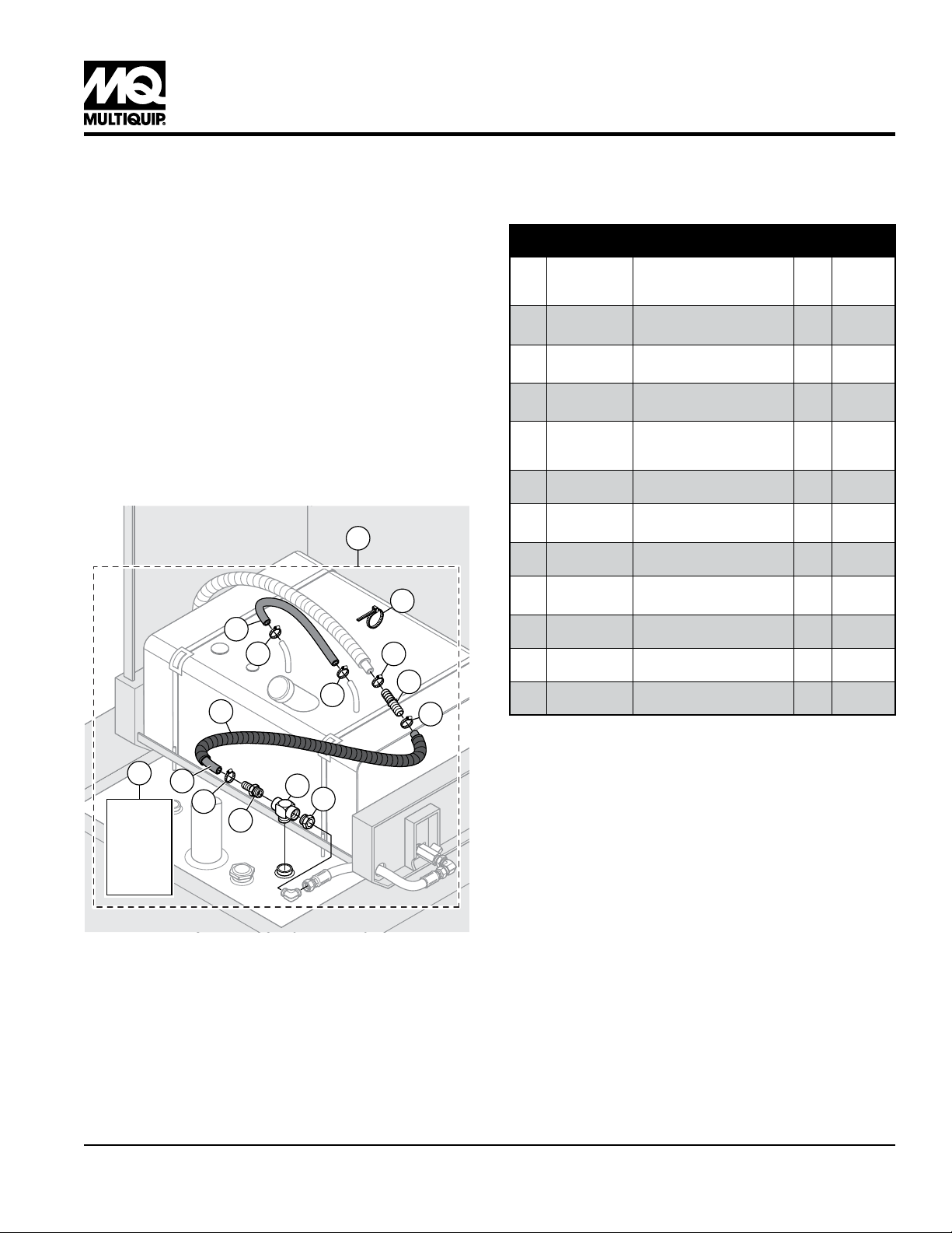
PARTS
Verify that all parts are accounted for. See Figure 1 and
Table 1.
1
9
8
5
5
10
5
7
5
Table 1. Return Fuel Line Kit
Item
No.
10 Protector, Spiral Hose 1
11 35499 Instructions, Return Fuel Line 1
Part No. Description QTY. Remarks
1 35500 Kit, Return Fuel Line 1
2
3
4 Fitting, 3/4MP x 1/2 Barb, Brass 1
5 Clamp, Hose Worm #8 1/2-1.00 5
6
7 Fitting, Brass, 8 Barb x 8 Barb 1
8
9 Tie, Cable Ty-Rap Black 10
Fitting, Bush 1/2FP x 3/4MP
Steel/Yel Zinc
Fitting, Tee, 3/4FP x 3/4MP x
3/4FP
Hose, Fuel, 1/2" ID, Return
Extension, 53 in. (134.6 cm)
Hose, Fuel, 1/2" ID, Vent,
24 in. (61 cm)
Includes
items 2-11
1
1
1
1
WORK SAFELY!
11
INSTRUCTIONS
6
5
4
3
2
Only a qualified service technician with proper training
should perform this installation. Follow all shop safety rules
when performing this installation.
PREPARATION
1. Make sure generator is turned off and engine is cool.
2. Place the generator in an area free of dirt and debris
Make sure it is on secure level ground with chock blocks
Figure 1. Return Fuel Line Kit
DCA400 SERIES — FUEL RETURN LINE KIT INSTRUCTIONS P/N 35499 — REV. #0 (01/26/11) — PAGE 1
underneath each wheel to prevent the generator from
rolling.
3. Disconnect negative battery cable from the battery.
4. Remove front cabinet panel to gain access to generator
fuel tank.
5. Remove trailer fuel tank cover to gain access to trailer
fuel tank.
Page 2
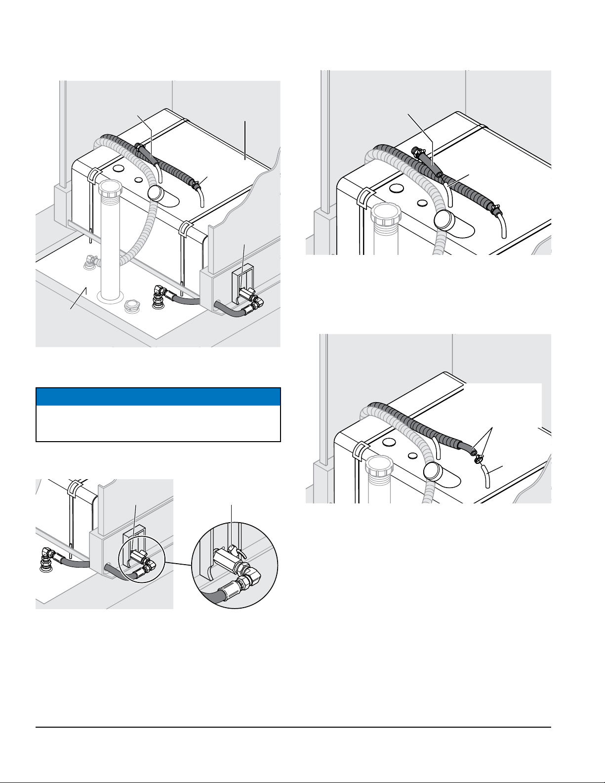
DISASSEMBLY
Figure 2 illustrates the unit’s current fuel line configuration.
2. Disconnect pick-up hose from pick-up port and discard.
See Figure 4.
Pick-Up
Hose
Trailer
Fuel Tank
Figure 2. Current Fuel Line Configuration
Generator
Fuel Tank
Engine
Return
Hose
Drain
Remove/Discard
Pick-Up Hose
Pick-Up
Port
Figure 4. Remove/Discard Pick-Up Hose
3. Disconnect engine return hose from return port. See
Figure 5.
NOTICE
Fuel leaks may occur when disconnecting hoses and
fittings. Wipe up any spilled fuel immediately.
1. Turn fuel shut-off valve to the OFF position (Figure 3).
Fuel Shut-Off
Drain
Figure 3. Fuel Shut-Off Valve (Off Position)
Valve (OFF Position)
Disconnect
Engine Return
Hose
Return
Port
Figure 5. Disconnect Engine Return Hose
DCA400 SERIES — FUEL RETURN LINE KIT INSTRUCTIONS P/N 35499 — REV. #0 (01/26/11) — PAGE 2
Page 3

4. Disconnect drain hose from trailer return port. See
Figure 6.
INSTALL NEW TRAILER RETURN PORT FITTINGS
Refer to Figure 8.
Trailer
Drain
Return
Port
Disconnect
Drain Hose
Figure 6. Disconnect Drain Hose
5. Remove fittings from trailer return port. Retain the 90º
fitting, and discard the others. See Figure 7.
Retain
90º Fitting
Remove
Fittings
3
2
4
Drain
Existing 90º
Fitting
Figure 8. New Trailer Return Port Fittings
Hose
NOTICE
Apply pipe sealant to all fittings.
1. Install Item 3, tee fitting, into trailer return port.
2. Install Item 2, straight fitting, into the right side of the
tee fitting.
3. Install existing 90º fitting into Item 2. Connect to drain
hose.
Trailer
Return Port
Figure 7. Remove Trailer Return Port Fittings
4. Install Item 4, straight fitting, into the left side of the tee.
DCA400 SERIES — FUEL RETURN LINE KIT INSTRUCTIONS P/N 35499 — REV. #0 (01/26/11) — PAGE 3
Page 4

INSTALL NEW RETURN EXTENSION HOSE
Refer to Figure 9.
1. Connect Item 6, return extension hose, to item 4.
Secure with clamp, Item 5.
2. Install Item 7, straight fitting, between extension hose
and existing engine return hose. Secure with clamps.
9
Engine
Return Hose
5
7
6
5
4
Figure 9. New Return Extension Hose
5
3. Install spiral tubing, Item 10, around return extension
hose. Secure with cable ties, Item 9. See Figure 10.
10
9
Figure 10. Spiral Tubing
INSTALL NEW VENT HOSE
1. Connect Item 8, vent hose, to generator pick-up port and
return port. Secure with clamps, Item 5. See Figure 11.
8
5
5
Return
Port
Pick-Up
Port
Figure 11. Vent Hose
DCA400 SERIES — FUEL RETURN LINE KIT INSTRUCTIONS P/N 35499 — REV. #0 (01/26/11) — PAGE 4
Page 5

2. Secure vent hose to engine return hose and engine
feed hose with cable ties, Item 9.
REASSEMBLY/TESTING
1. Turn fuel shut-off valve to the ON position (Figure 3).
9
9
9
Engine
Feed
Hose
Figure 12. Secure Vent Hose
Engine
Return
Hose
2. Reconnect negative battery cable to the battery.
3. Start generator as referenced in the Operation Manual.
4. Check for fuel leaks.
5. Replace front cabinet panel and trailer fuel tank cover.
DCA400 SERIES — FUEL RETURN LINE KIT INSTRUCTIONS P/N 35499 — REV. #0 (01/26/11) — PAGE 5
Page 6

HERE’S HOW TO GET HELP
© COPYRIGHT 2011, MULTIQUIP INC.
Multiquip Inc
the MQ logo are registered trademarks of Multiquip Inc. and may not be used, reproduced, or altered without written permission. All other trademarks are the property
The information and specifications included in this publication were in effect at the time of approval for printing. Illustrations, descriptions, references and technical data contained in
this document are for guidance only and may not be considered as binding. Multiquip Inc. reserves the right to discontinue or change specifications, design or the information published
DCA400 Series
Fuel Return Modification
PLEASE HAVE THE MODEL AND SERIAL
NUMBER ON-HAND WHEN CALLING
United StateS
Multiquip Corporate Office MQ Parts Department
18910 Wilmington Ave.
Carson, CA 90746
Contact: mq@multiquip.com
Service Department Warranty Department
800-421-1244
310-537-3700
Technical Assistance
800-478-1244 Fax: 310-943-2238
Tel. (800) 421-1244
Fax (800) 537-3927
Fax: 310-537-4259 800-421-1244
800-427-1244
310-537-3700
310-537-3700
Fax: 800-672-7877
Fax: 310-637-3284
Fax: 310-943-2249
mexico United Kingdom
MQ Cipsa Multiquip (UK) Limited Head Office
Carr. Fed. Mexico-Puebla KM 126.5
Momoxpan, Cholula, Puebla 72760 Mexico
Contact: pmastretta@cipsa.com.mx
Tel: (52) 222-225-9900
Fax: (52) 222-285-0420
Unit 2, Northpoint Industrial Estate,
Globe Lane,
Dukinfield, Cheshire SK16 4UJ
Contact: sales@multiquip.co.uk
Canada
Multiquip
4110 Industriel Boul.
Laval, Quebec, Canada H7L 6V3
Contact: jmartin@multiquip.com
Tel: (450) 625-2244
Tel: (877) 963-4411
Fax: (450) 625-8664
Tel: 0161 339 2223
Fax: 0161 339 3226
of their respective owners and used with permission.
in this publication at any time without notice and without incurring any obligations.
and
Your Local Dealer is:
 Loading...