

Page 1

OPERATION AND PARTS MANUAL
WHISPERWATT™ SERIES
MODEL DCA180SSK (STD.)
60 HZ GENERATOR
(KOMATSU SA6D108E-2 DIESEL ENGINE)
Revision #3 (06/11/09)
PARTS LIST NO. C0874300704A
To find the latest revision of this
publication, visit our website at:
www.mqpower.com
THIS MANUAL MUST ACCOMPANY THE EQUIPMENT AT ALL TIMES.
Page 2
PROPOSITION 65 WARNING
PAGE 2 — DCA-180SSK — PARTS AND OPERATION MANUAL — REV. #3 (06/11/09)
Page 3

NOTE PAGE
DCA-180SSK — PARTS AND OPERATION MANUAL— REV. #3 (06/11/09) — PAGE 3
Page 4

TABLE OF CONTENTS
MQ Power DCA-180SSK
AC Generator
Proposition 65 Warning ..............................................2
Table Of Contents ......................................................4
Parts Ordering Procedures ........................................5
Rules For Safe Operation ...................................... 6-9
Towing ......................................................................10
Trailer Safety Guidelines .................................... 11-17
Trailer Wiring Diagram..............................................18
Electrical Brake Troubleshooting .............................. 19
Hydraulic Brake Troubleshooting .............................20
Operation And Safety Decals ............................. 21-24
Specifications ...........................................................25
General Information ........................................... 26-27
Major Components ..................................................28
Dimensions (Top, Side And Rear)............................29
Control Panel...................................................... 30-31
Engine Operating Panel ..................................... 32-33
Output Terminal Panel Overview ........................ 34-39
Installation .......................................................... 40-41
Pre-Setup ........................................................... 42-45
Load Application ......................................................46
Generator Start-Up Procedure (Manual) ........... 47-51
Generator Start-up Procedure (Auto) ................ 52-53
Generator Shut-Down Procedure ............................54
Maintenance ...................................................... 55-57
Generator Wiring Diagram .......................................58
Engine Wiring Diagram ............................................59
Troubleshooting (Engine) ................................... 60-61
Troubleshooting (Engine/Generator) ....................... 62
Troubleshooting (MPEC) .......................................... 63
Explanation Of Codes In Remarks Column .............64
Suggested Spare Parts ............................................65
COMPONENT DRAWINGS
Generator Assembly .......................................... 66-67
Control Panel Assembly ..................................... 68-69
Control Box Assembly ........................................ 70-71
Engine Radiator Assembly ................................. 72-73
Engine Operating Panel Assembly .................... 74-75
Output Terminal Assembly ................................. 76-77
Battery Assembly ............................................... 78-79
Muffler Assembly ............................................... 80-81
Fuel Tank Assembly ........................................... 82-83
Enclosure Assembly ........................................... 84-87
Enclosure Lining Assembly ................................ 88-89
Enclosure (Rubber Seals) .................................. 90-91
Name Plate and Decals ..................................... 92-95
Terms and Conditions Of Sale — Parts ...................96
NOTE
Specification and part
number are subject to
change without notice.
PAGE 4 — DCA-180SSK — PARTS AND OPERATION MANUAL — REV. #3 (06/11/09)
Page 5
PARTS ORDERING PROCEDURES
Ordering parts has never been easier!
Choose from three easy options:
Effective:
Order via Internet (Dealers Only):
Order parts on-line using Multiquip’s SmartEquip website!
■
View Parts Diagrams
■
Order Parts
Goto www.multiquip.com and click on
Order Parts
to log in and save!
Order via Fax (Dealers Only):
All customers are welcome to order parts via Fax.
Domestic (US) Customers dial:
Order via Phone:
Non-Dealer Customers:
Contact your local Multiquip Dealer for
parts or call 800-427-1244 for help in
If you have an MQ Account, to obtain a
Username and Password, E-mail us at:
parts@multiquip.com.
To obtain an MQ Account, contact your
internet
Use the
on
Standard orders
Fax
your order in and qualify for a 2% Discount
on
Standard orders
Domestic (US) Dealers Call:
and qualify for a 5% Discount
for all orders which include
for all orders which include
International Customers
tact their local Multiquip Representatives
Note: Discounts Are Subject To Change
Note: Discounts Are Subject To Change
should con-
❒❒
❒
❒❒
❒❒
❒
❒❒
❒❒
❒
❒❒
❒❒
❒
❒❒
❒❒
❒
❒❒
www.mqpower.com
DCA-180SSK — PARTS AND OPERATION MANUAL— REV. #3 (06/11/09) — PAGE 5
When ordering parts, please supply:
❒❒
❒
Dealer Account Number
Dealer Name and Address
Shipping Address (if different than billing address)
Return Fax Number
Applicable Model Number
All orders are treated as
and will ship the same day if received prior
WE ACCEPT ALL MAJOR CREDIT CARDS!
❒❒
Standard Orders
Specify Preferred Method of Shipment:
✓
UPS/Fed Ex
■
Priority One
■
Ground
■ Next Day
✓ DHL
✓
Tru c k
Page 6
RULES FOR SAFE OPERATION
CAUTION:CAUTION:
CAUTION:
CAUTION:CAUTION:
Failure to follow instructions in this manual
may lead to serious injury or even death!
This equipment is to be operated by
trained and qualified personnel only! This
equipment is for industrial use only.
The following safety guidelines should always be used when
operating the DCA-180SSK portable generator:
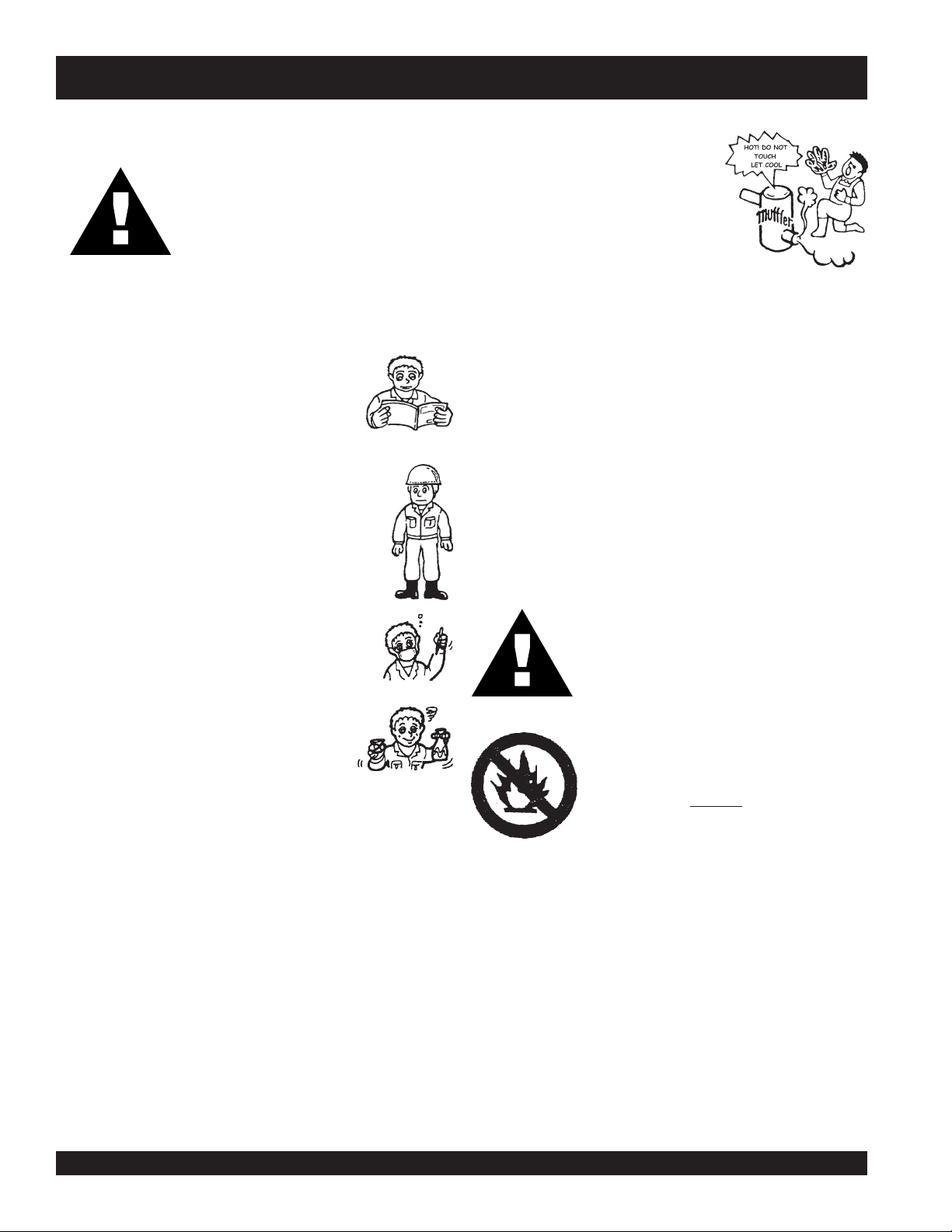
GENERAL SAFETY
■
DO NOT operate or service this equipment before
reading this entire manual.
■
This equipment should not be operated by
persons under 18 years of age.
■
NEVER operate this equipment without proper
protective clothing, shatterproof glasses,
steel-toed boots and other protective devices
required by the job.
RULES FOR SAFE OPERATION
■
NEVER touch the hot exhaust
manifold, muffler or cylinder. Allow
these parts to cool before servicing
engine or generator.
■
High Temperatures – Allow the engine to cool before
adding fuel or performing service and maintenance
functions. Contact with
burns.
■
The engine of this generator requires an adequate free
flow of cooling air. NEVER operate the generator in any
enclosed or narrow area where free flow of the air is
restricted. If the air flow is restricted it will cause serious
damage to the generator or engine and may cause injury
to people. The generator engine gives off DEADLY carbon
monoxide gas.
CAUTIONCAUTION
CAUTION
CAUTIONCAUTION
hot
components can cause serious
:
■
NEVER operate this equipment when not feeling
well due to fatigue, illness or taking medicine.
■
NEVER operate this equipment under the
influence or drugs or alcohol.
■
NEVER use accessories or attachments, which are not
recommended by MQ Power for this equipment. Damage
to the equipment and/or injury to user may result.
■
Manufacturer does not assume responsibility for any
accident due to equipment modifications.
■
Whenever necessary, replace nameplate, operation and
safety decals when they become difficult read.
■
Always check the machine for loosened threads or bolts
before starting.
■
NEVER operate the generator in an explosive atmosphere
or near combustible materials. An explosion or fire could
result causing severe
■
Topping-off to filler port is dangerous, as it tends to spill
fuel.
■
Always refuel in a well-ventilated area,
away from sparks and open flames.
■
Always use extreme caution when
working with flammable liquids. When
refueling, stop the engine and allow it to
cool. DO NOT smoke around or near the
machine. Fire or explosion could result
from fuel vapors, or if fuel is spilled on a
hot engine.
bodily harm or even death.
PAGE 6 — DCA-180SSK — PARTS AND OPERATION MANUAL — REV. #3 (06/11/09)
Page 7
RULES FOR SAFE OPERATION
CAUTIONCAUTION
CAUTION
CAUTIONCAUTION
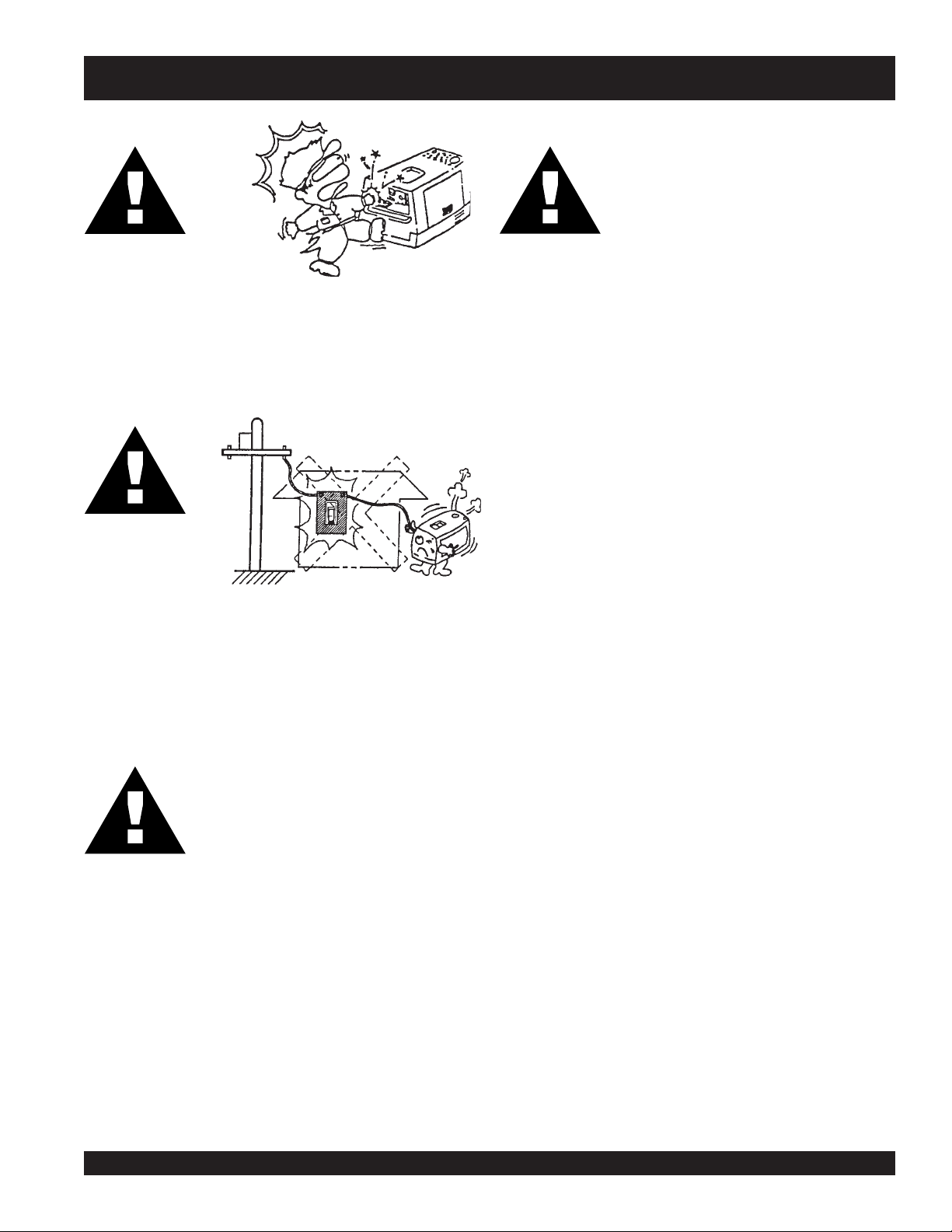
■
NEVER touch output terminals during operation. This is
extremely dangerous.
contact with the output terminals.
CAUTIONCAUTION
CAUTION
CAUTIONCAUTION
■
Backfeed to a utility system can cause electrocution
and.or property damage. Do not connect to any
building's electrical system except through an approved
device or after building main switch is opened.
:
Always stop the machine when
:
CAUTIONCAUTION
CAUTION
CAUTIONCAUTION
Radiator
1. Radiator Cap - Removing the radiator cap while the
2. Coolant Drain Plug - Removing the coolant drain plug
3. Engine Oil Drain Plug - Removing the engine oil drain
:
■
DO NOT touch or open any of the below
mentioned components while the
generator is running. Always allow
sufficient time for the engine and generator
to cool before performing maintenance.
engine is hot will result in high pressurized, boiling water
to gush out of the radiator, causing severe scalding to
any persons in the general area of the generator.
while the engine is hot will result in hot coolant to gush
out of the coolant drain plug, therefore causing severe
scalding to any persons in the general area of the
generator.
plug while the engine is hot will result in hot oil to gush
out of the oil drain plug, therefore causing severe
scalding to any persons in the general area of the
generator.
CAUTIONCAUTION
CAUTION
CAUTIONCAUTION
:
Never use damaged or worn cables when
connecting power tools or equipment to the
generator. Make sure power connecting
cables are securely connected to the
generator’s output terminals, insufficient
tightening of the terminal connections may
cause damage to the generator and
electrical shock.
DCA-180SSK — PARTS AND OPERATION MANUAL— REV. #3 (06/11/09) — PAGE 7
Page 8
RULES FOR SAFE OPERATION
■
Battery
CAUTIONCAUTION
CAUTION
CAUTIONCAUTION
The battery contains acids that can cause injury to the eyes
and skin. To avoid eye irritation, always wear safety glasses.
Use well insulated gloves when picking up the battery. Use
the following guidelines when handling the battery:
:
Never over fill the battery with water above
the upper limit.
NEVER Run engine without air filter. Severe engine
damage may occur.
■
Always service air cleaner frequently to prevent carburetor
malfunction.
■
Always disconnect the battery before performing service
on the generator.
■
Always be sure the operator is familiar with proper safety
precautions and operations techniques before using
generator.
■
Always store equipment properly when not in use.
Equipment should be stored in a clean, dry location out of
the reach of children.
■
DO NOT leave the generator running in the manual mode
unattended.
■
DO NOT allow unauthorized people to operate this
equipment.
■
Always read, understand, and follow procedures in
Operator’s Manual before attempting to operate equipment.
■
1. DO NOT drop the battery. There is the possibility of risk
that the battery may explode.
2. DO NOT expose the battery to open flames, sparks,
cigarettes etc. The battery contains combustible gases
and liquids. If these gases and liquids come in contact
with a flame or spark, an explosion could occur.
3. Always keep the battery charged. If the battery is not
charged a buildup of combustible gas will occur.
4. Always keep battery charging and booster cables in good
working condition. Repair or replace all worn cables.
5. Always recharge the battery in an open air environment,
to avoid risk of a dangerous concentration of combustible
gases.
6. In case the battery liquid (dilute sulfuric acid) comes in
contact with
immediately with plenty of water.
7. In case the battery liquid (dilute sulfuric acid) comes in
contact with your eyes, rinse eyes immediately with
plenty of water, then contact the nearest doctor or hospital,
and seek medical attention.
clothing or skin
, rinse skin or clothing
Refer to the
technical questions or information.
Loading and Unloading (Crane)
■
Before lifting, make sure the generator's lifting hook is
secure and that there is no apparent damage to the
generator itself (loose screws, nuts and bolts). If any
part is loose or damaged, please take corrective action
before lifting.
■
Always drain fuel prior to lifting.
■
Always make sure crane or lifting device has been
properly secured to the hook of guard frame on generator.
■
NEVER lift the machine while the engine is running.
■
Use adequate lifting cable (wire or rope) of sufficient
strength.
■
When lifting the generator, always use the balanced
center-point suspension hook and lift straight upwards.
■
NEVER allow any person or animal to stand underneath
the machine while lifting.
■
When loading the generator on a truck, be sure to use
the front and back frame bars as a means to secure the
generator during transport.
Komatsu Engine Owner's Manual
for engine
PAGE 8 — DCA-180SSK — PARTS AND OPERATION MANUAL — REV. #3 (06/11/09)
Page 9

Transporting
■
Always shutdown engine before transporting.
■
Tighten fuel tank cap securely.
■
Drain fuel when transporting generator over long distances
or bad roads.
■
Always tie-down the generator during transportation by
securing the generator.
■
If generator is mounted on a trailer, make sure trailer
complies with all local and state safety transportation
laws. See page 10 for basic towing procedures.
Emergencies
■
Always know the location of the nearest
and
first aid kit
Also know the phone numbers of the nearest
doctor
Maintenance Safety
■
and
NEVER lubricate components or attempt service on a
running machine.
. Know the location of the nearest telephone.
fire department
.
fire extinguisher
ambulance
,
RULES FOR SAFE OPERATION
■
Always allow the machine a proper amount of time to
cool before servicing.
■
Keep the machinery in proper running condition.
■
Fix damage to the machine immediately and always
replace broken parts.
■
Dispose of hazardous waste properly. Examples of
potentially hazardous waste are used motor oil, coolant,
fuel, and fuel filters.
■
DO NOT use plastic containers to dispose of hazardous
waste.
■
DO NOT pour waste, oil, coolant or fuel directly onto the
ground, down a drain or into any water source
DCA-180SSK — PARTS AND OPERATION MANUAL— REV. #3 (06/11/09) — PAGE 9
Page 10
■
Towing Safety Precautions
CAUTION:CAUTION:
CAUTION:
CAUTION:CAUTION:
Check with your county or state safety
towing regulations department before
towing your generator.
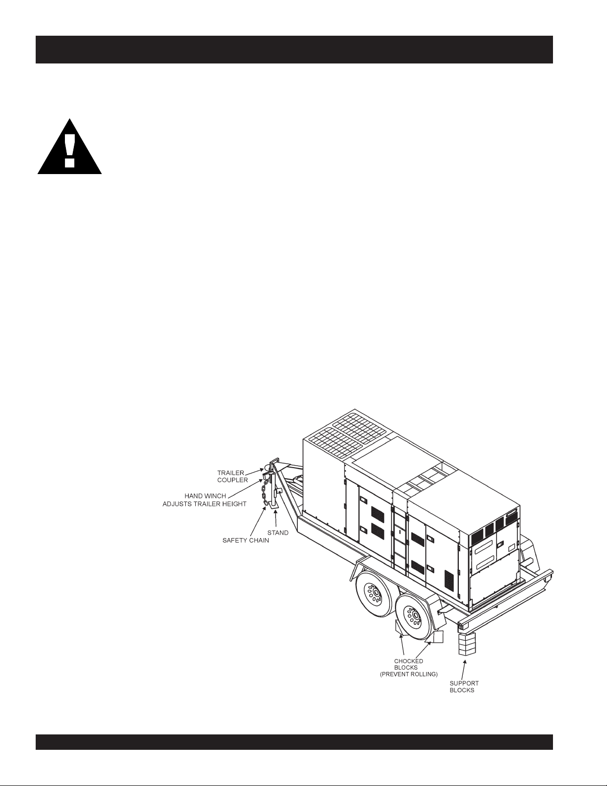
To reduce the possibility of an accident while transporting
the generator on public roads, always make sure the trailer
(Figure 1) that supports the generator and the towing vehicle
are in good operating condition and both units are
mechanically sound.
The following list of suggestions should be used when towing
your generator:
■
Make sure the hitch and coupling of the towing vehicle
are rated equal to, or greater than the trailer "gross vehicle
weight rating" (GVWR).
■
ALWAYS inspect the hitch and coupling for wear. NEVER
tow a trailer with defective hitches, couplings, chains
etc.
■
Check the tire air pressure on both towing vehicle and
trailer. Also check the tire tread wear on both vehicles.
ALWAYS attach trailer's safety chain to bumper of towing
vehicle.
■
ALWAYS make sure the vehicle and trailer directional,
backup, brake, and trailer lights are connected and working
properly.
■
Remember the maximum speed unless otherwise posted for
highway towing is 45 MPH. Recommended off-road towing
is not to exceed 10 MPH or less depending on type of terrain.
■
Place
while parked.
■
Place
prevent
■
Use the trailer's hand winch to adjust the height of the trailer,
then insert locking pin to lock wheel stand in place, while
parked.
■
Avoid sudden stops and starts. This can cause skidding, or
jackknifing. Smooth, gradual starts and stops will improve
gas milage.
■
Avoid sharp turns to prevent rolling.
■
Remove wheel stand when transporting.
■
DO NOT transport generator with fuel in tank.
DCA-180SSK — TOWING
chocked blocks
support blocks
tipping
underneath wheel to prevent
underneath the trailer's bumper to
, while parked.
rolling,
■
ALWAYS make sure the trailer is equipped with a "Safety
Chain".
Figure 1. Generator with Trailer
PAGE 10 — DCA-180SSK — PARTS AND OPERATION MANUAL — REV. #3 (06/11/09)
Page 11

DCA-180SSK — TRAILER-SAFETY GUIDELINES
CAUTION:CAUTION:
CAUTION:
CAUTION:CAUTION:
ALWAYS make sure the trailer is in good
operating condition. Check the tires for
proper inflation and wear. Also check the
wheel lug nuts for proper tightness.
Explanation of Chart:
This section is intended to provide the user with trailer service and maintenance information. The service and maintenance guidelines referenced in this section apply a wide
range of trailers. Remember periodic inspection of the trailer
will ensure safe towing of the equipment and will prevent
damage to the equipment and personal injury.
It is the purpose of this section to cover the major maintenance components of the trailer. The following trailer components will be discussed in this section:
Brakes
Tires
Lug Nut Torquing
Suspension
Electrical
Brake Troubleshooting Tables
Use the following definitions while reading Table 1.
1. Fuel Cell - Provides an adequate amount of fuel for
the equipment in use. Fuel cells must be empty when
transporting equipment.
2. Braking System - System employed in stopping the
trailer. Typical braking systems are electric, surge, hydraulic, hydraulic-surge and air.
7. Coupler - Type of hitch used on the trailer for towing.
8. Tire Size - Indicates the diameter of the tire in inches
(10,12,14, etc.), and the width in millimeters
(175,185,205, etc.). The tire diameter must match the
diameter of the tire rim.
9. Tire Ply - The tire ply (layers) number is rated in letters;
2-ply,4-ply,6-ply, etc.
10. Wheel Hub - The wheel hub is connected to the trailer’s
axle.
11. Tire Rim - Tires are mounted on a tire rim. The tire rim
must match the size of the tire.
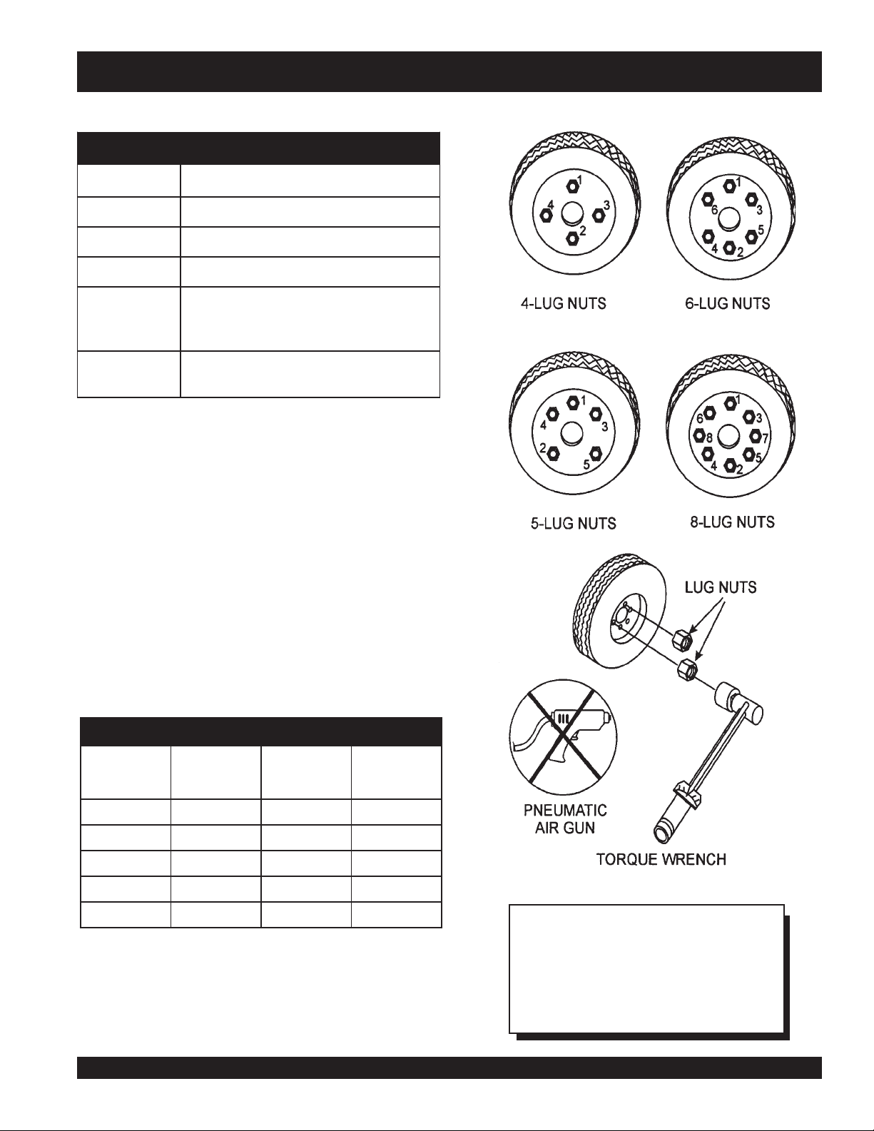
12. Lug Nuts - Used to secure the wheel to the wheel hub.
Always use a torque wrench to tighten down the lug
nuts. See Table 4 and Figure 5 for lug nut tightening and
sequence.
13. Axle - Indicates the maximum weight the axle can support in pounds, and the diameter of the axle expressed
in inches (see Table 3 on page 17). Please not that
some trailers have a double axle. This will be shown as
2-6000 lbs., meaning two axles with a total weight capacity of 6000 pounds.
14. Suspension - Protects the trailer chassis from shock
transmitted through the wheels. Types of suspension
used are leaf, Q-flex, and air ride.
15. Electrical - Electrical connectors (looms) are provided
with the trailer so the brake lights and turn signals can
be connected to the towing vehicle. See page 16 for
proper wiring connections.
16. Application - Indicates which units can be employed
on a particular trailer.
3. GVWR- Gross Vehicle Weight Rating (GVWR), is the
maximum number of pounds the trailer can carry, including the fuel cell (empty).
4. Frame Length - This measurement is from the ball
hitch to the rear bumper (reflector).
5. Frame Width - This measurement is from fender to
fender.
6. Jack Stand - Trailer support device with maximum
pound requirement from the tongue of the trailer.
DCA-180SSK — PARTS AND OPERATION MANUAL— REV. #3 (06/11/09) — PAGE 11
Page 12

DCA-180SSK — TRAILER-SPECIFICATIONS
snoitacificepS.1elbaT
LEDOM NOITACILPPA LEUF
LLEC
W01-RLRT,522WDS
01-RLRT,21GLT,01ACD
FX01-RLRT,21-GLT,01ACD
W522-RLRT,SREDLEW
004WLB-RLRT004-WLBONCIRTCELESBL0072"451TSAM/W
X05-RLRT52-ACDONONSBL0072"421"55.BL008
FX05-RLRT52-ACDLAG14ONSBL0072"421"55.BL008
W07-RLRT07,06-,54-ACDONEGRUSSBL0007"681"77.BL0002
X07-RLRT07,06-,54-ACDTPOEGRUSSBL0007"831"66.BL0002
FX07-RLRT07,06-,54-ACDLAG35EGRUSSBL0007"831"66.BL0002
FX001-RLRT521,001-ACDLAG051EGRUSCILUARDYHSBL0007"091"6
521/58-RLRT,001,58-ACD
FX051-RLRT081,051-ACDLAG00
FX022-RLRT022-ACDLAG052EGRUSCILUARDYHSBL00041"222"38.BL0005
03-RLRT003-ACDLAG052EGRUSCILUARDYHSBL00081"832"38.BL0005
FX0
FX004-RLRT004-ACDLAG053CIRTCELESBL00081"832"38.BL000
FX006-RLRT008,006-ACDLAG055RIASBL00003"483"69.BL0005
XS008-RLRT008,006-ACDLAG055RIASBL00003"483"69.BL
7AD
003WLT,052WGS
51-ACD
003-WLT,51ACD
SS000
521
ONONSBL0091"69"05.BL008
ONONSBL0091"69"05.BL008
LAG25ONSBL0091"69"05.BL008
ONONSBL0022"58"24.BL008
LAG541CILUARDYHSBL00001"681"77.BL0002
2EGRUSCILUARDYHSBL06111"402"48.BL0005
EKARB
METSYS
RWVG EMARF
EMARF
HTGNEL
"421O/W
HTDIW
"55
)LLAT"87(
UF
7.BL0002
KCAJ
DNATS
LEEHWTLITLLUF
EEHWTLITLLUF
L
LEEHWTLITLLUF
LEEHWTLITLLUF
.BL008
LE
EHWTLITLLUF
LEEHWTLITLLUF
LEEHWTLITLL
DAPTALF
DAPTALF
DAPTALF
DAPTALF
DAPTALF
DAPTALF
DAPTALF
DAPTALF
5
DAPTALF
DAPTALF
0005
DAPTALF
PAGE 12 — DCA-180SSK — PARTS AND OPERATION MANUAL — REV. #3 (06/11/09)
Page 13

DCA-180SSK — TRAILER-SPECIFICATIONS
)t'noC(snoitacificepS.1elbaT
LEDOM RELPUOC SERIT SLEEHW ELXA SBUH NOISNEPSUS LACIRTCELE
W01-RLRTSSALCLLAB"2
ELBATSUJDA2
01-RLRTSSALCLLAB"2
JDA2
FX01-RLRTSSALCLLAB"2
W522-RLRTSSALCLLAB"2
WLB-RLRT
004
X05-RLRTSSALCLLAB"2CRL31-87B"05.4X"31.sbl0053
FX05-RLRTSSALCLLAB"2CRL31-87B"05.4X"31.sbl0053
W07-RLRTSSALCLLAB"2
X07-RLRTSSALCLLAB"2
FX07-RLRTSSALCLLAB"2
A2
DA"3
FX001-RLRT6/5-2ELBATSUJDA
ELBATSU
ELBATSUJDA2
ELBATSUJDA2
SSALCLLAB"2
ELBATSUJD
ELBATSUJ
ELBATSUJDA"3
ELBATSUJDA"3
EYE"3TPO
C31-571"05.4X"312X2#0022GUL5FAEL3/WMOOLERIW4
C31-571"5.4X"312X2#0022GUL5FAEL3TALFELOP4
C31-571"5.4X"312X2#0022GUL5FAEL3TALF
B31-571"5.4X312X2#0022GUL5XELFQTALFELOP4
C31-571"5.4X312X2#0022GUL5FAEL3TALFELOP4
C41-502
)4(SAIB
C41-502
)4(SAIB
C41-502
)4(SAIB
C51-502
)4(SAIB
"5X"41.sbl0053
X"41sbl0053
"5
"5X"41.sbl0053
"5.5X"41sbl0053
TALFELOP4
ELOP4
GUL5FAEL4REBBURELOP
"8/3-2
GUL5FAEL4REBBURELOP4
"8/3-2
GUL5FAEL5REBBURELOP4
"3
GUL5FAEL5REBBURELOP4
"3
GUL5FAEL
"3
GUL5FAEL5MOOLERIW4
"3
5REBBURELOP4
4
TALF
TALF
TALF
TALF
TALF
LRT6/5-2ELBATSUJDA
521/58-R
FX051-RLRTEYELLAB"3E61-057
FX022-RLRTEYE"3
FX003-RLRTEYE"3
FX004-RLRTEYE
FX006-RLRTLEEHWHT5H5.71R57/512TS
RA008-RLRTLEEHWHT5H5.71R57/512TS
"3
D51R57/522TS
EYE"3TPO
ELBATSUJDA
ELBATSUJDA
ELBATSUJDA
)4(LAIDAR
)4(SAIB
E61R58/532TS
)4(LAIDAR
E61R58/532TS
)6(LAIDAR
E61R58/532TS
)6(LAIDAR
DAR
)8(LAI
)8(LAIDAR
"6x"41sbl0006-)2(GUL6FAEL7MOOLERIW4
"7X"61sbl0006-)2(GUL8FAEL7MOOLERIW4
"7X"61sbl0007-)2(GUL
"7X"61sbl0006-)2(GUL8XELFQMOOLERIW4
"7X"61.sbl0007-)3(GUL8XELFQMOOLERIW4
"7X"61sbl00001-)3(GUL8FAEL7MOOLERIW6
"7X"61sbl00001-)3(GUL8EDIR-RIAM
8XELFQMOOLERIW4
OOLERIW6
DCA-180SSK — PARTS AND OPERATION MANUAL— REV. #3 (06/11/09) — PAGE 13
Page 14

DCA-180SSK — TRAILER SAFETY GUIDELINES
Brakes
If your trailer has a braking system, the brakes should be
inspected the first 200 miles of operation. This will allow the
brake shoes and drums to seat properly. After the first 200
mile interval, inspect the brakes every 3,000 miles. If driving
over rough terrain, inspect the brakes more frequently.
Electric Brakes
Electrically actuated brakes (Figure 2) are similar to hydraulic
brakes. The basic difference is that hydraulic brakes are
actuated by an electromagnet.
Listed below are some of the advantages that electric brakes
have over hydraulic brakes:
Brake system can be manually adjusted to provide the
corrected braking capability for varying road and load
conditions
Brake system can be modulated to provide more or less
braking force, thus easing the brake load on the towing
vehicle
Brake system has very little lag time between the time
the vehicle’s brakes are actuated and the trailer’s brakes
are actuated
Brake system can provide an independent emergency
brake system
Remember in order to properly synchronize the tow vehicle’s
braking to the trailer’s braking, can only be accomplished by
road testing. Brake lockup, grabbiness or harshness is due
to lack of synchronization between the tow vehicle and the
trailer being towed or under-adjusted brakes.
Before any brake synchronizations adjustments can be made,
the trailer brakes should be burnished-in by applying the
brakes 20-30 times with approximately a 20 m.p.h. decrease
in speed, e.g. 40 m.p.h. to 20 m.p.h. Allow ample time for
brakes to cool between application. This allows the brake
shoes to slightly be seated into the brake drum surface.
Figure 2 displays the major electric brake components that
will require inspection and maintenance. Please inspect these
components as required.
Electric Brake Adjustment
1. Place the trailer on jack stands. Make sure the jack
stands are placed on secure level ground.
2. Check the wheel and drum for free rotation.
3. Remove the adjusting hole cover from the adjusting slot
at the bottom brake backing plate.
4. With a screwdriver or standard adjusting tool, rotate the
star wheel of the adjuster assembly to expand the brake
shoes.
5. Adjust the brake shoes outward until the pressure of the
lining against the wheel drum makes the wheel difficult
to turn.
6. Rotate the star wheel in the opposite direction until the
wheel rotates freely with slight lining drag.
7. Replace the adjusting hole cover and lower the trailer to
the ground.
8. Repeat steps 1 through 6 on the remaining brakes.
PAGE 14 — DCA-180SSK — PARTS AND OPERATION MANUAL — REV. #3 (06/11/09)
Page 15
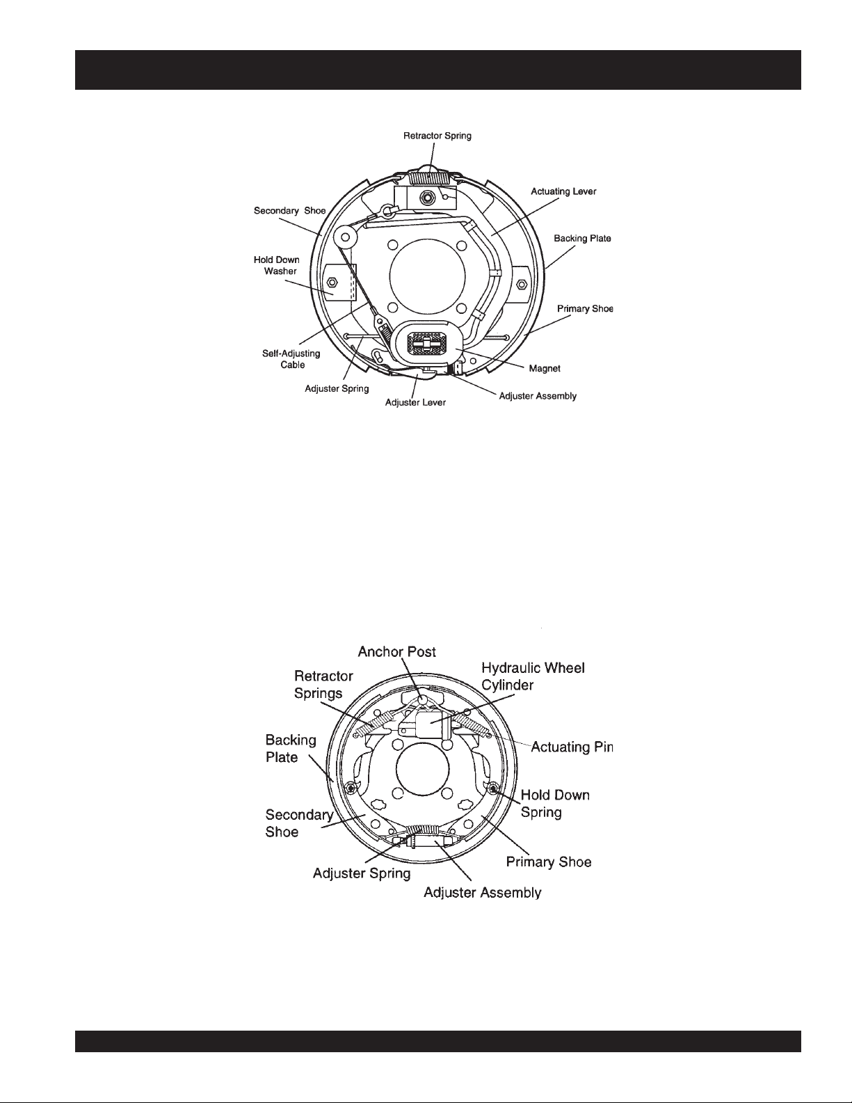
DCA-180SSK — TRAILER SAFETY GUIDELINES
Figure 2. Electrical Brake Components
Hydraulic/Air/Surge Brakes
Hydraulic brakes (Figure 3) should not require any special
attention with the exception of routine maintenance such as
shoe and lining replacement. These brakes can be adjusted
in the same manner as electric brakes. Brake lines should
be periodically checked for cracks, kinks, or blockage.
Figure 3 below displays the major hydraulic/air/surge brake
components that will require inspection and maintenance.
Please inspect these components as required using steps 1
through 6 as referenced in the electric brake adjustments
section.
Figure 3. Hydraulic Brake Components
DCA-180SSK — PARTS AND OPERATION MANUAL— REV. #3 (06/11/09) — PAGE 15
Page 16
DCA-180SSK — TRAILER SAFETY GUIDELINES
Tires/Wheels/Lug Nuts
Tires and wheels are a very important and critical
components of the trailer. When specifying or replacing the
trailer wheels it is important the wheels, tires, and axle are
properly matched.
CAUTION:
DO NOT attempt to repair or modify a
wheel. DO NOT install in inner tube to
correct a leak through the rim. If the rim
is cracked, the air pressure in the inner
tube may cause pieces of the rim to
explode (break off) with great force and
cause serious eye or bodily injury.
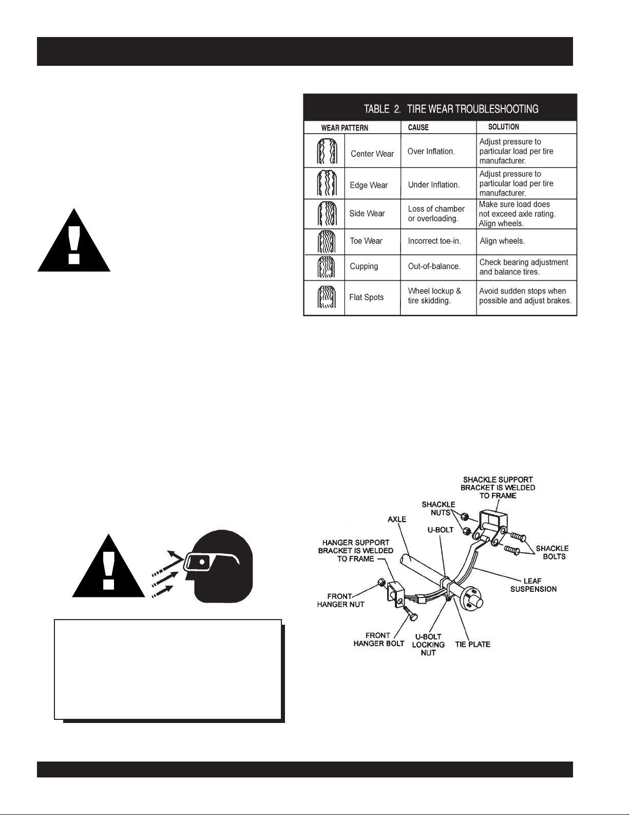
Suspension
The leaf suspension springs and associated components
(Figure 4) should be visually inspected every 6,000 miles for
Tire Wear/Inflation
Tire inflation pressure is the most important factor in tire life.
Pressure should be checked cold before operation DO NOT
bleed air from tires when they are hot. Check inflation
pressure weekly during use to insure the maximum tire life
and tread wear.
Table 2 (Tire Wear Troubleshooting) will help pinpoint the
causes and solutions of tire wear problems.
signs of excessive wear, elongation of bolt holes, and
loosening of fasteners. Replace all damaged parts
(suspension) immediately. Torqued suspension components
as detailed in Table 3.
CAUTION:
NOTE
ALWAYS wear safety glasses when removing
or installing force fitted parts. Failure to comply
may result in serious injury.
PAGE 16 — DCA-180SSK — PARTS AND OPERATION MANUAL — REV. #3 (06/11/09)
Figure 4. Major Suspension Components
Page 17
metI ).sbL-.tF(euqroT
TLOB-U"8/353-XAM03-NIM
TLOB-U"2/106-XAM54-NIM
SHACKLE BOLT
SPRING EYE BOLT
DCA-180SSK — TRAILER SAFETY GUIDELINES
TLOB-U"61/706-XAM54-NIM
.
SNUG FIT ONL Y
LOC KING NU TS OR C OTT ER P INS A RE P ROV IDE D
TO RETAIN NUT
PARTS MUST ROTATE FREELY
-
BOLT ASSEMBLY
stnemeriuqeReuqroTnoisnepsuS.3elbaT
.
.
SHOULDER TYPE
SHACKLE BOLT
05-XAM03-NIM
Lug Nut Torque Requirements
It is extremely important to apply and maintain proper wheel
mounting torque on the trailer. Be sure to use only the
fasteners matched to the cone angle of the wheel. Proper
procedure for attachment of the wheels is as follows:
1. Start all wheel lug nuts by hand.
2. Torque all lug nuts in sequence. See Figure 5. DO NOT
torque the wheel lug nuts all the way down. Tighten
each lug nut in 3 separate passes as defined by Table 4.
3. After first road use, retorque all lug nuts in sequence.
Check all wheel lug nuts periodically.
stnemeriuqeReuqroTeriT.4elbaT
eziSleehW
ssaPtsriF
SBL-TF
dnoceS
ssaP
SBL-TF
ssaPdrihT
SBL-TF
"2152-0204-5356-05
"3152-0204-5356-05
"4152-0206-05021-09
"5152-0206-05021-09
"6152-0206-05021-09
DCA-180SSK — PARTS AND OPERATION MANUAL— REV. #3 (06/11/09) — PAGE 17
Figure 5. Wheel Lug Nuts Tightening Sequence
NOTE
NEVER use an pneumatic air gun to
tighten wheel lug nuts.
Page 18
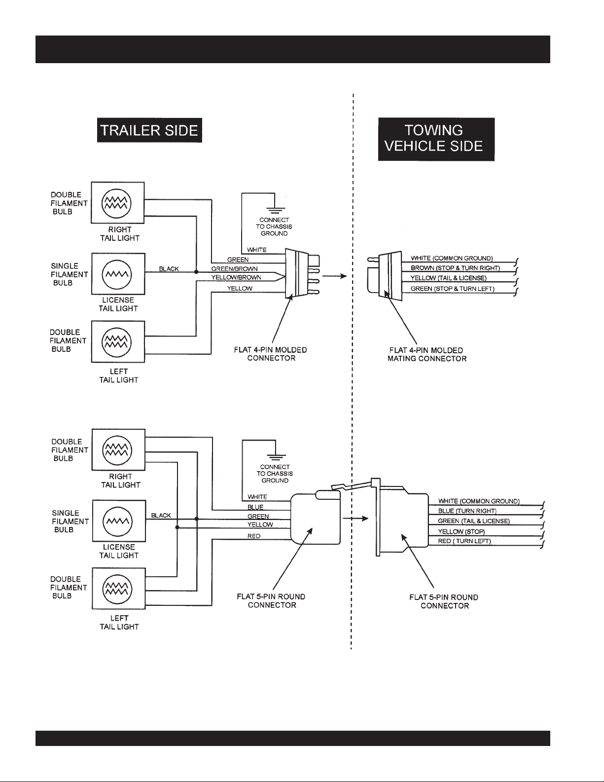
DCA-180SSK — TRAILER-WIRING DIAGRAM
NOTE:
LIGHTS ARE ORIENTED FROM THE DRIVER’S SEAT
PAGE 18 — DCA-180SSK — PARTS AND OPERATION MANUAL — REV. #3 (06/11/09)
Page 19
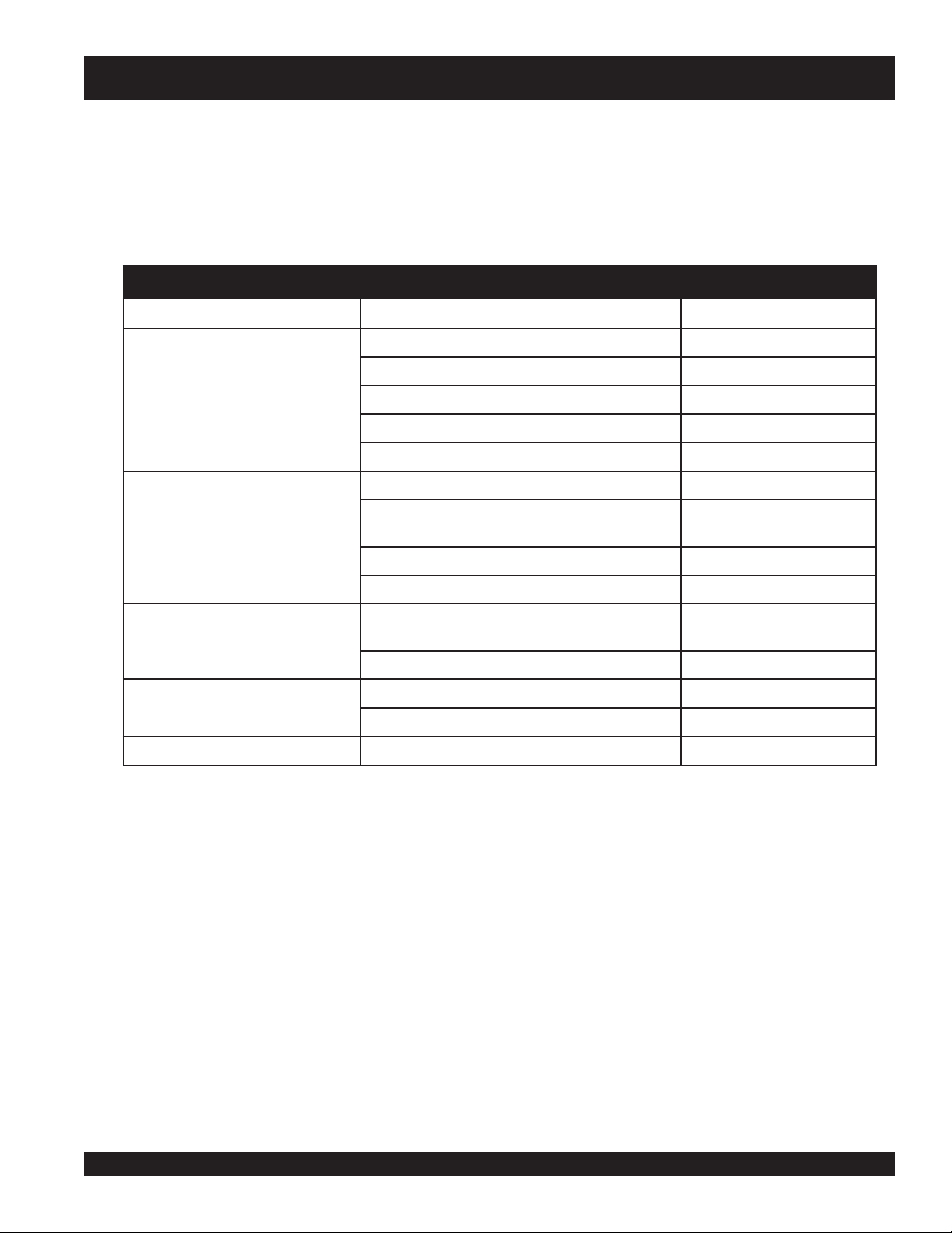
DCA-180SSK — TRAILER-BRAKE TROUBLESHOOTING
gnitoohselbuorTekarBcirtcelE.5elbaT
motpmyS esuaCelbissoP noituloS
tnettimretnIrosekarBoN
sekarB
sekarBrosekarBkaeW
ediSenOotlluP
gnikcoLrotneb,esoolstnenopmocekarB
sekarB
sekarBysioN?de
sekarBgniggarD?detsujdaleehwehtfosgnira
?seriwnekorbrostiucricnepoynA.tcerrocdnadniF
?stiucrictrohsynA.tcerr
?rellortnocytluaF.tcerrocdnatseT
?snoitcennocesoolynA.riaperdnadniF
?eruceseriwdnuorG.erucesdnadn
?sgninilrostengamnolioroesaerG.ecalperronaelC
?dedorrocsnoitcennoCtcerr
?devoorgroderocssmurdekarB.ecalperroenihcaM
?dezinorhcnyssekarB.tcerroC
?nekorb
?dnuor-fo-tuosmurdekarB.ecalpeR
tacirbulmetsyS.etacirbuL
?tcerrocstnenopmocekarB.tcerrocdnaecalpeR
eB.tsujdA
iF
ocdnadniF
ocdnanaelC
.noisorrocfoesuac
.stnenopmocecalpeR
DCA-180SSK — PARTS AND OPERATION MANUAL— REV. #3 (06/11/09) — PAGE 19
Page 20
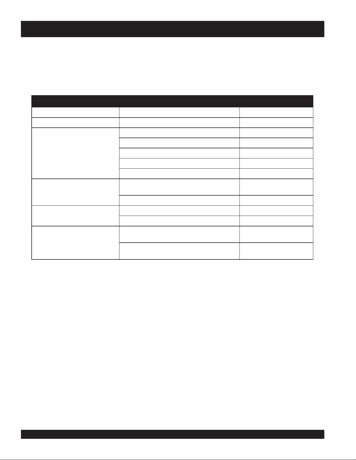
DCA-180SSK — TRAILER-BRAKE TROUBLESHOOTING
gnitoohselbuorTekarBciluardyH.6elbaT
motpmyS esuaCelbissoP noituloS
sekarBoN?deknikronekorbenilekarB.ecalperroriapeR
sekarBrosekarBkaeW
ediSenOotlluP
sekarBgnikcoLrotneb,esoolstnen
sekarBysioN?detacirbulmetsyS.etacirbuL
sekarBgniggarDnirotcerrocssenkcihtgninilekarB
rB.ecalperrohsinrubeR
erusserperiT.yllauqeseritllaetalfnI
opmocekarB
?nekorb
ir
?dezalggninileka
?dedaolrevoreliarT.thgiewtcerroC
?devoorgroderocssmurdekarB.ecalperroenihcaM
?tcerroc
?elxaemasehtnodehctamnuseriT.serithctaM
?dnuor-fo-tuosmurdekarB.ecalpeR
?tcerrocstnenopmocekarB.tcerrocdnaecalpeR
?noitisopgnorwthg
?diulftcerrocrodiulfekarbhguonEstraprebburecalpeR
.stnenopmocecalpeR
dnaseohswenllatsnI
.sgninil
.diulf4todhtiwllif
PAGE 20 — DCA-180SSK — PARTS AND OPERATION MANUAL — REV. #3 (06/11/09)
Page 21
DCA-180SSK — OPERATION AND SAFETY DECALS
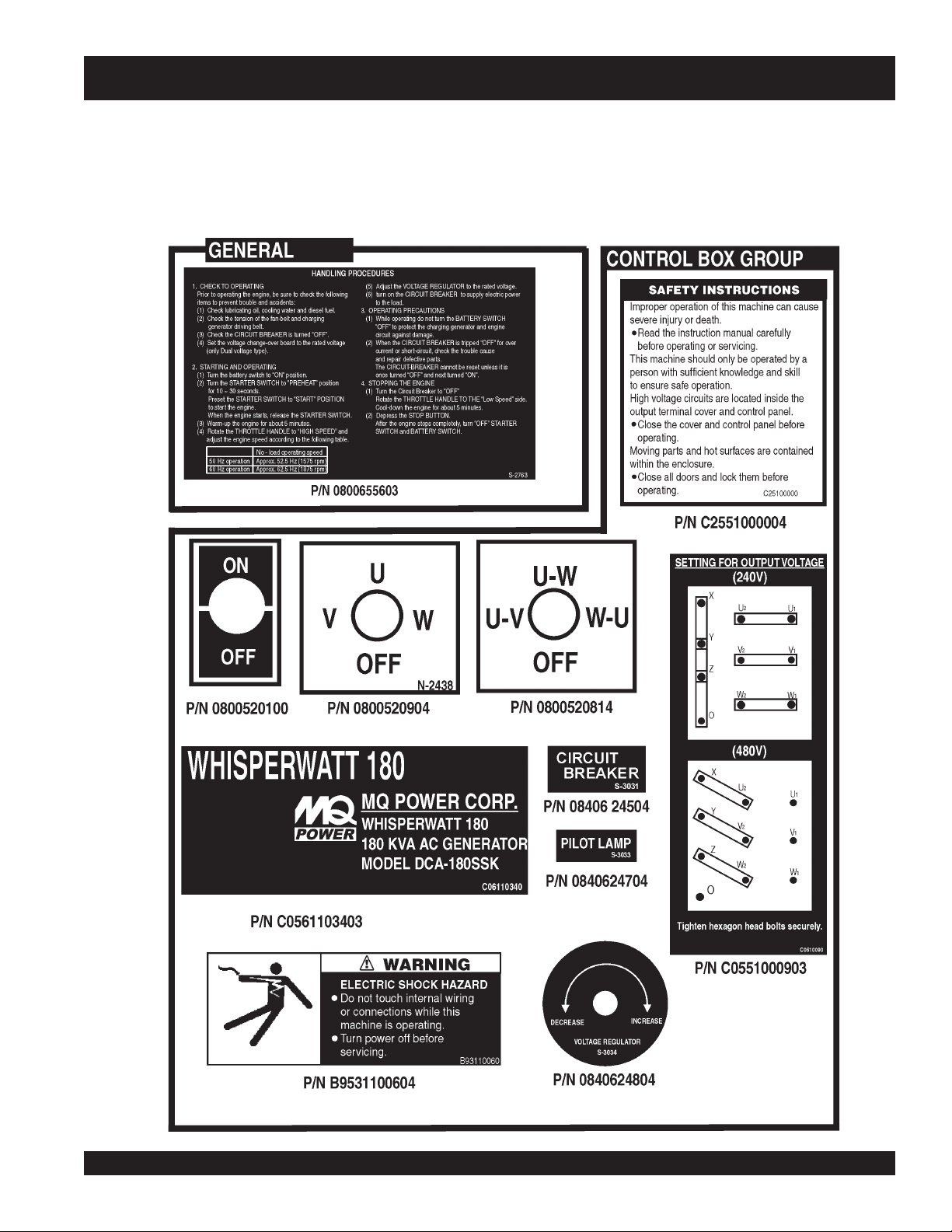
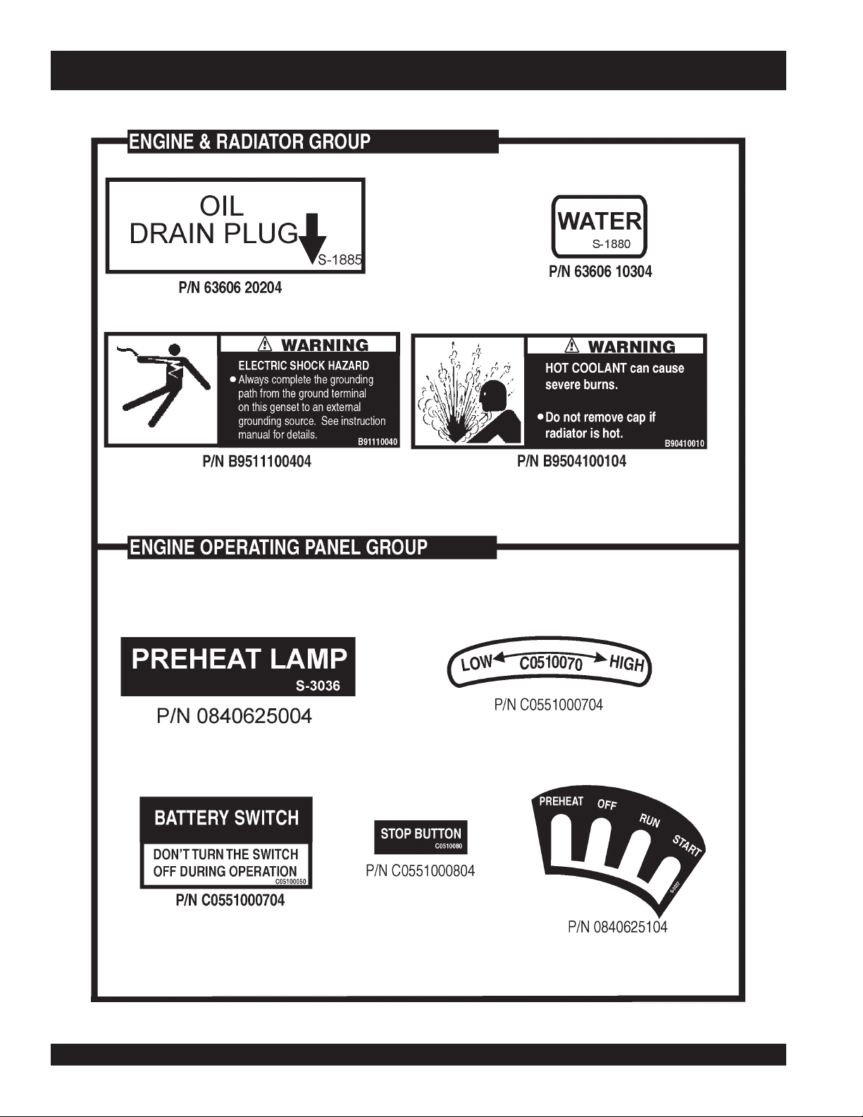
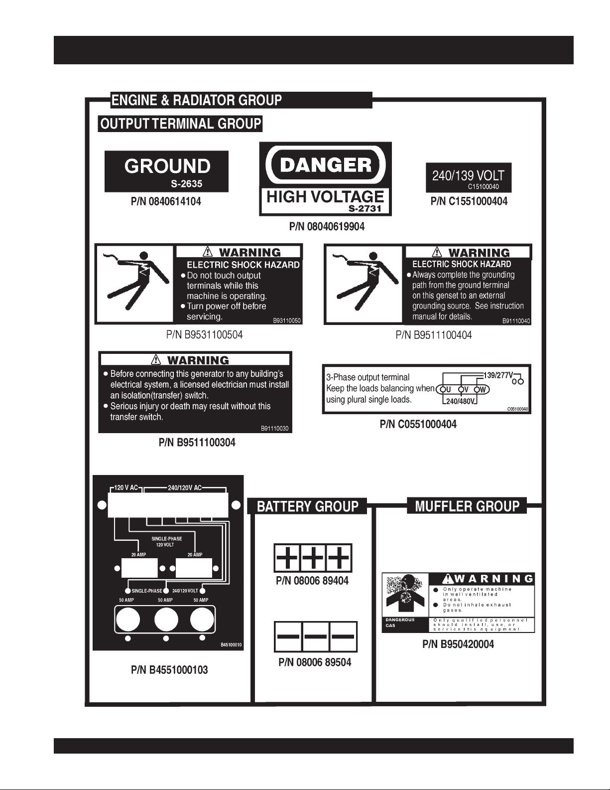
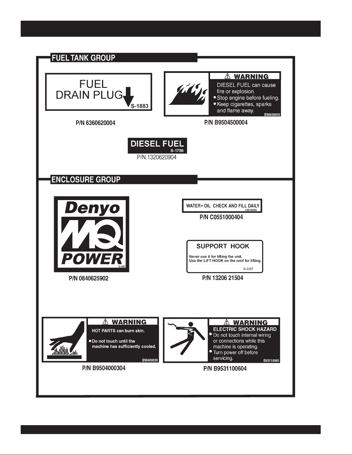
Machine Safety Decals
The DCA-180SSK generator is equipped with a number of safety decals. These decals are provided for operator safety and
maintenance information. The illustration below and on the preceding pages shows the decals as they appear on the machine.
Should any of these decals become unreadable, replacements can be obtained from your dealer.
DCA-180SSK — PARTS AND OPERATION MANUAL— REV. #3 (06/11/09) — PAGE 21
Page 22
DCA-180SSK — OPERATION AND SAFETY DECALS
PAGE 22 — DCA-180SSK — PARTS AND OPERATION MANUAL — REV. #3 (06/11/09)
Page 23
DCA-180SSK — OPERATION AND SAFETY DECALS
DCA-180SSK — PARTS AND OPERATION MANUAL— REV. #3 (06/11/09) — PAGE 23
Page 24
DCA-180SSK — OPERATION AND SAFETY DECALS
PAGE 24 — DCA-180SSK — PARTS AND OPERATION MANUAL — REV. #3 (06/11/09)
Page 25

DCA-180SSK — SPECIFICATIONS
ledoMKSS081-ACD
epyT rotarenegsuonorhcnysepytdetcetorpnepo,detalitnevfles,dleifgnivloveR
snoitacificepS.7elbaT
snoitacificepSrotareneG
rAlartueNhtiwratS
esahP3
epSmpr0081
de
noitcennoCerutam
tuptuOybdnatS)WK4.851(AVK891
tuptuOemirP)WK441(AVK081
egatloVV084roV042
ycneuqerFzH06
rotcaFrewoP8.0
rewoPCA.xuAzH06,esahPelgniS
egatloVV021
tuptuO)2xWK4.2(WK8.4
ledoM2-E801D6ASUSTAMOK
snoitacificepSenignE
epyTrelooc-retfahtiwdegrahc-obrut,noitcejnitcerid,delooc-retaw,elcyC4
oNsrednilyc6
DCA-180SSK — PARTS AND OPERATION MANUAL— REV. #3 (06/11/09) — PAGE 25
srednilyCfo.
ekortSxeroB)mm031xmm801(.ni1.5x.ni2.4
tuptuOdetaRmpr0081/PH712
tnemecalpsiD)cc0517(.ni.uc634
gni
tratScirtcelE
yticapaCtnalooC)sretil32(.lag1.6
yticapaCliOebuL)sretil52(.lag6.6
noitpmusnoCleuF)daolllufta(r
yrettaB2xHA021-V21
leuFleuFleseiD2#
h/)sretil4.63(.lag6.9
Page 26

DCA-180SSK — GENERAL INFORMATION
DCA-180SSK FAMILIARIZATION
Generator
The MQ Power Model DCA-180SSK is a 144 kW
that has been designed as a high quality portable (requires
a trailer for transport) power source for telecom sites, lighting
facilities, power tools, submersible pumps and other
industrial and construction machinery.
Engine Control Panel
The “Engine Control Panel” is provided with the following:
Tachometer
Water Temperature Gauge
Oil Pressure Gauge
Charging Ammeter Gauge
Engine Speed Switch
Pre-Heat Button
Pre-Heat Lamp
Emergency Stop Button
Battery Switch
Ignition Key Switch
MPEC Module (on some models)
generator
Control Box
The “Control Box” is provided with the following:
Main Circuit Breaker 500 amps
Over-Current Relay
High Idle Adjust Trimmer
Microprocessor Controlled Alarm System
The DCA-180SSK generator is equipped with various alarms
and LED status indicators. These alarms and status indicators
are provided to add safety to the generator when operating
under normal conditions. The DCA-180SSK generator is
designed to shutdown in the event of low oil, high coolant
temperature, low battery and other operation conditions that
may cause severe damage to the generator.
Open Delta Excitation System
The DCA-180SSK generator is equipped with the state of
the art "
system consist of an electrically independent winding wound
among stationary windings of the AC output section.
Open-Delta
" excitation system. The open delta
Generator Control Panel
The “Generator Control Panel” is provided with the following:
Output Voltage Adjustment Knob
Frequency Meter (Hz)
AC Ammeter (Amps)
AC Voltmeter (Volts)
Ammeter Change-Over Switch
Voltmeter Change-Over Switch
Panel Light
Panel Light Switch
Pilot Lamp
Output Terminal Panel
The “Output Terminal Panel” is provided with the following:
Two 120V GFCI receptacles, 20 amp
Three 240/139V output receptacles, 50 amp
Two 120V input receptacles, 20 amp
3 Load Circuit Breakers 265V @65 amps
2 Load GFCI Circuit Breakers 265V@ 20amps
There are four connections: A, B, C and D. During steady
loads, the power to the
is supplied from the parallel connections of A to B, A to D,
and C to D. These three phases are rectified and are used as
the current for the exciter section.
During a heavy load, such as motor starting, the AVR
switches the configuration of the Open-Delta to the series
connection B to C. This has the effect of adding the voltages
of each phase to provide better voltage response during heavy
loads.
The connections of the AVR to the AC output windings are
for the sole purpose of sensing. No power is required from
these windings.
The open-delta design provides virtually unlimited excitation
current due to its independent power supply offering maximum
motor starting capabilities. The excitation does not have a
"
fixed ceiling
required load.
" and responds according the demands of the
Automatic Voltage Regulator
(AVR)
PAGE 26 — DCA-180SSK — PARTS AND OPERATION MANUAL — REV. #3 (06/11/09)
Page 27

DCA-180SSK — GENERAL INFORMATION (OPTIONS)
Engine
The DCA-180SSK is powered by a 4 cycle, water cooled,
turbocharged KOMATSU Model SA6D108E-2
engine. This engine is designed to meet every performance
requirement for the generator. Reference Table 7, page 25
for engine specifications.
In keeping with MQ Power's policy of constantly improving
its products, the specifications quoted herein are subject to
change without prior notice.
The basic controls and indicators for the DCA-180SSK
generator are addressed on the following pages.
Mechanical Governor System
The mechanical governor system control the RPM of the
engine. When the engine demands increase or decrease,
the mechanical governor system regulates the frequency
variation to ±1.0%. The electronic governor option
increases frequency variation to ±0.25%.
Electronic Governor System
The electronic governor system is made up of two parts, an
electronic controller that monitors frequency variation as the
load increases and decreases and an electronic actuator
that controls the engine throttle. The frequency is regulated
at ±0.25 to help protect sensitive equipment.
Jacket Water Heater (OPTIONAL)
The jacket water heater is a 1500-watt heater designed to
keep the coolant from freezing in the engine block. The
heater is thermostatically controlled and once an acceptable
engine temperature is achieved it will cycle on and off,
operating only about 1/3 of the time. This becomes a very
energy efficient option compared to a direct immersion block
heater. It is designed to keep the engine between 100 and
120 degrees Fahrenheit. This is not a throwaway heater. It
is completely serviceable.
diesel
gasoline
CAUTION :
There is a bleed screw on the valve on the engine block.
After service of either the heater or the cooling system, it is
possible to create an air bubble in this area. The air bubble
would prevent hot water created by the jacket water heater
from circulating, if the air bubble were not allowed to escape.
This bleed screw allows for the bleeding process to be
accomplished.
Battery Charger (OPTIONAL)
The battery charger will operate in a ‘BOOST’ mode until
the battery’s current acceptance falls to 70% of the
charger’s rating. The charger will then go into a ‘FLOAT’
mode, where it discharges a lower voltage until an AC
failure, or the battery is discharged.
Fuel Water Separator
The fuel water separator separates water mixed in the
fuel. It has an indicator to let the operator know to drain
the water. See maintenance section for instructions how
to drain water from separator.
ALWAYS unplug the jacket water heater
before servicing.
In normal conditions, 20 to 15 minutes is all that is required
to raise the engine temperature of a cold engine to 100
degrees Fahrenheit.
DCA-180SSK — PARTS AND OPERATION MANUAL— REV. #3 (06/11/09) — PAGE 27
Page 28
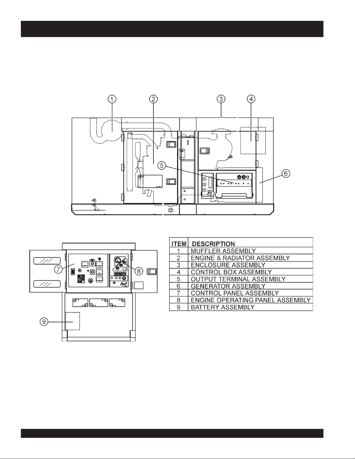
DCA-180SSK — MAJOR COMPONENTS
Figure 6. Major Components
PAGE 28 — DCA-180SSK — PARTS AND OPERATION MANUAL — REV. #3 (06/11/09)
Page 29
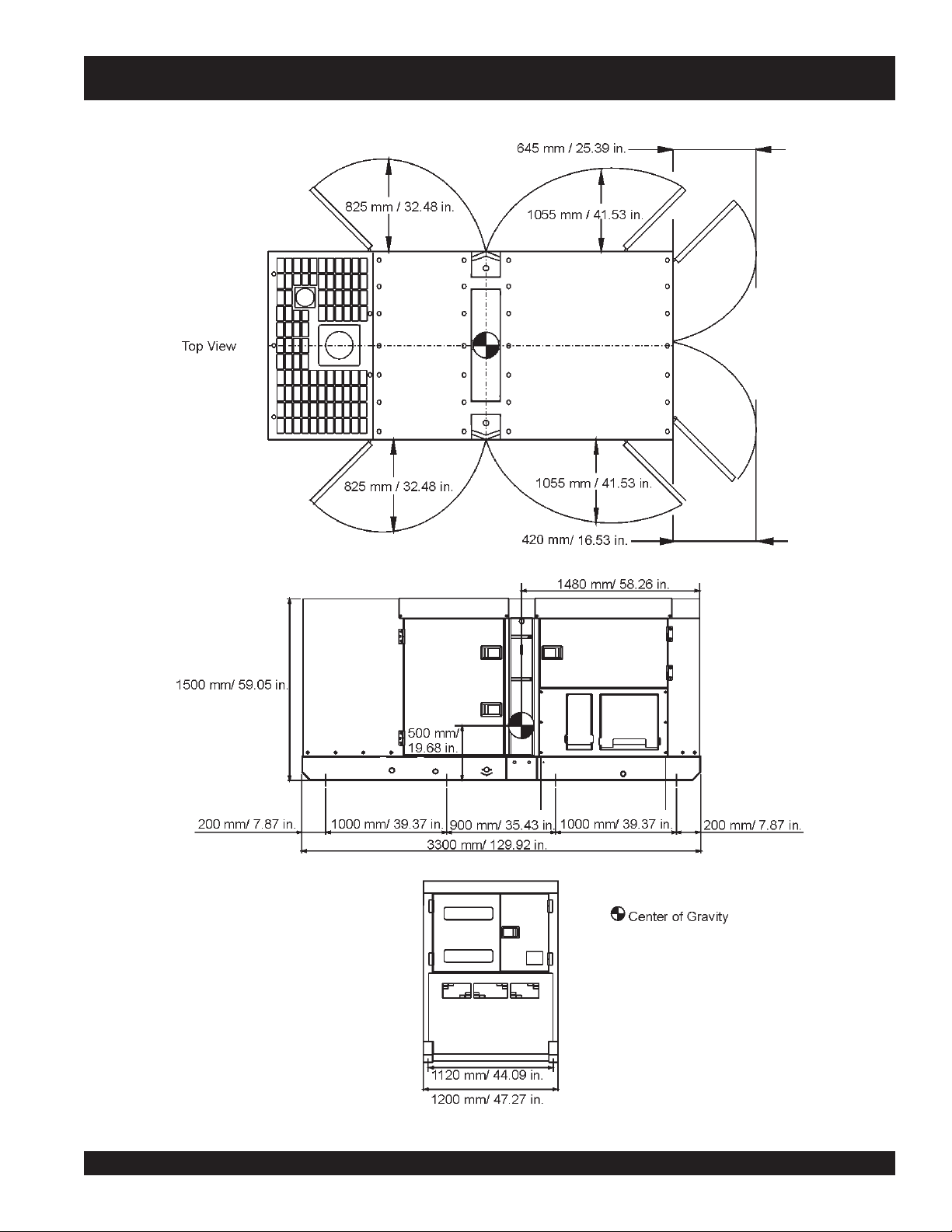
DCA-180SSK — DIMENSIONS (TOP, SIDE, AND REAR)
Figure 7. Dimensions
DCA-180SSK — PARTS AND OPERATION MANUAL— REV. #3 (06/11/09) — PAGE 29
Page 30
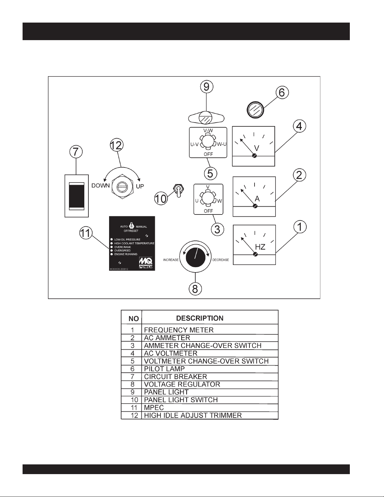
DCA-180SSK — CONTROL PANEL
Figure 8. Control Panel
PAGE 30 — DCA-180SSK — PARTS AND OPERATION MANUAL — REV. #3 (06/11/09)
Page 31

DCA-180SSK — CONTROL PANEL
The definitions below describe the controls and functions of the
DCA-180SSK "
1. Frequency Meter – Indicates the output frequency in hertz
(Hz). Normally 60 Hz ±1 Hz .
2. AC Ammeter – Indicates the amount of current the load is
drawing from the generator.
3. Ammeter Change-Over Switch – This switch allows the
AC ammeter to indicate the current flowing to the load
connected to any phase of the output terminals, or to be
switched off.
4. AC Voltmeter – Indicates the single phase output voltage
present at the UVW terminals.
5. Voltmeter Change-Over Switch – This switch allows the
AC voltmeter to indicate phase to phase voltage between
any two phases of the output terminals or to be switched off.
6. Pilot Lamp – Indicates that the generator is working
properly.
7. Main Circuit Breaker – This three-pole, 500 amp main
breaker is provided to protect the UVW voltage output
terminals from overload.
8. Voltage Regulator Control – Allows manual adjustment
of the generator’s output voltage.
9. Panel Light – Normally used in dark areas or at night time.
When activated, panel lights will illuminate. When the
generator is not in use be sure to turn the panel light switch
to the OFF position.
10. Panel Light Switch – When activated will turn on control
panel light.
11. MPEC – Microprocessor Engine Control Module –
(MPEC) has a vertical row of status LED's (Figure 9), that
when lit, indicate that an
engine malfunction (fault), has
been detected. When a fault
has been detected the MPEC
will evaluate the fault and if the
fault is major will shutdown the
generator.
Control Panel
" (Figure 8).
If the engine does not engage (start) by the third attempt, the
engine will be shutdown by the MPEC's " Over Crank Protection"
mode. If the engine engages at a speed (RPM's) that is not safe,
the MPEC will shutdown the engine by initializing the "Over
Speed Protection" mode.
Also the MPEC will shutdown the generator in the event of low oil
pressure, high coolant temperature, low coolant level, and loss
of magnetic pickup. These conditions can be observed by
monitoring the LED status indicators on the front of the MPEC
module.
A. Off/Manual/Auto Switch – This switch controls the
B. Low Oil Pressure – Indicates the engine pressure
C. High Coolant Temperature – Indicates the engine
D. Overcrank Shutdown – Indicates the unit has
E. Overspeed Shutdown – Indicates the engine is
F. Engine Running – Indicates that engine is running
running of the generator. If this switch is left in the
"OFF" position, the generator will not run. When this
switch is set to the
will start immediately.
If the generator is to be connected to a building's AC
power source via a transfer switch (isolation), place
the switch in the
generator will monitor the AC line output from the
building's power source.
has fallen below 15 psi. The oil pressure is detected
using variable resistive values from the oil pressure
sending unit. This is considered a
temperature has exceeded 215
temperature is detected using variable resistive
values from the temperature sending unit. This is
considered a
attempted to start a pre- programmed number of
times, and has failed to start. The number of cycles
and duration are programmable. Typical
programmable start settings is 3 cycles with a 10
second duration .This is considered a
running at an unsafe speed. This is considered a
major
fault.
at a safe operating speed.
manual
auto
major
position, the generator
position. In this position the
major
fault.
F. The engine
fault.
major
fault.
Figure 9. MPEC Module
During
engine for 10 seconds before disengaging.
cranking cycle
, The MPEC will attempt to crank the
DCA-180SSK — PARTS AND OPERATION MANUAL— REV. #3 (06/11/09) — PAGE 31
12. High Idle Adjust Trimmer – Use this trimmer to adjust the
engine speed.
Page 32

DCA-180SSK — ENGINE OPERATING PANEL
Figure 10. Engine Operating Panel
PAGE 32 — DCA-180SSK — PARTS AND OPERATION MANUAL — REV. #3 (06/11/09)
Page 33

DCA-180SSK — ENGINE OPERATING PANEL
The definitions below describe the controls and functions of the
DCA-180SSK "
1. Tachometer – Indicates engine speed in RPM’s for 60 Hz
operation. This meter should indicate 1800 RPM’s when
the rated load is applied. In addition a built in hour meter
will record the number of operational hours that the
generator has been in use.
2. Charging Ammeter Gauge – Indicates the current being
supplied by the engine’s alternator which provides current
for generator’s control circuits and battery charging system.
3. Oil Pressure Gauge – During normal operation this gauge
be should read in the “GREEN” zone. When starting the
generator the oil pressure mar read a little bit higher, but
after the engine warms up the oil pressure should return to
the green zone.
4. Water Temperature Gauge – During normal operation
this gauge be should read in the “GREEN” zone.
5. Fuel Gauge - Detects the amount of fuel available for
operation.
6. Engine Warning Display Module – This module display’s
the following engine failures:
A. Overheat Lamp – This lamp goes ON when
the cooling water temperature rises
abnormally. If the lamp goes ON during
normal operation of the generator, the
emergency shutdown device will stop the
engine automatically.
B. Low Oil Pressure Lamp – During normal
operation of the generator this lamp should
remain OFF. When the Auto-OFF/ResetManual switch is set to the “Manual” position
to start the engine, the lamp will be lit. After
the oil pressure rises after start-up the lamp
will go OFF. If this lamp is ever lit (ON) during normal
operation of the generator, the emergency shutdown
device will stop the engine automatically.
C. Low Fuel Level Lamp – When this lamp is
ON, it is time to stop the engine and add
fuel. Remember to let the engine cool before
adding fuel.
Engine Operating Panel
" (Figure 10).
D. Low Battery Fluid Lamp – This lamp
goes ON when the battery fluid is low. If
this lamp goes ON during normal
operation of the generator, stop the
engine and fill the battery with distilled
water to the specified level.
E. Clogged Air Filter Lamp – This lamp goes
ON when the air filter is clogged. If this lamp
goes ON during normal operation of the
generator, stop the engine and replace the air
filter.
7. Speed Switch- Adjusts the speed of the
engine from high to low.
8. Pre-Heat Lamp – Indicates that the glow
plugs of the diesel engine are hot and the
engine is ready to be started.
9. Pre-Heat Button – Press hold this button until
the preheat lamp is lit (ON).
10. Emergency Stop Switch – Push
this button inward to stop the engine
in the event of an emergency. DO
NOT use this button as a means of
stopping the engine. Turn the button
clockwise to disengage the stop
function.
11. Battery Switch – This switch should
be set to the ON position during normal
operation. When the engine has been
stop, place this switch in the OFF
position. DO NOT turn this switch during
normal operation, it could cause
damage to the electrical equipment.
DCA-180SSK — PARTS AND OPERATION MANUAL— REV. #3 (06/11/09) — PAGE 33
Page 34

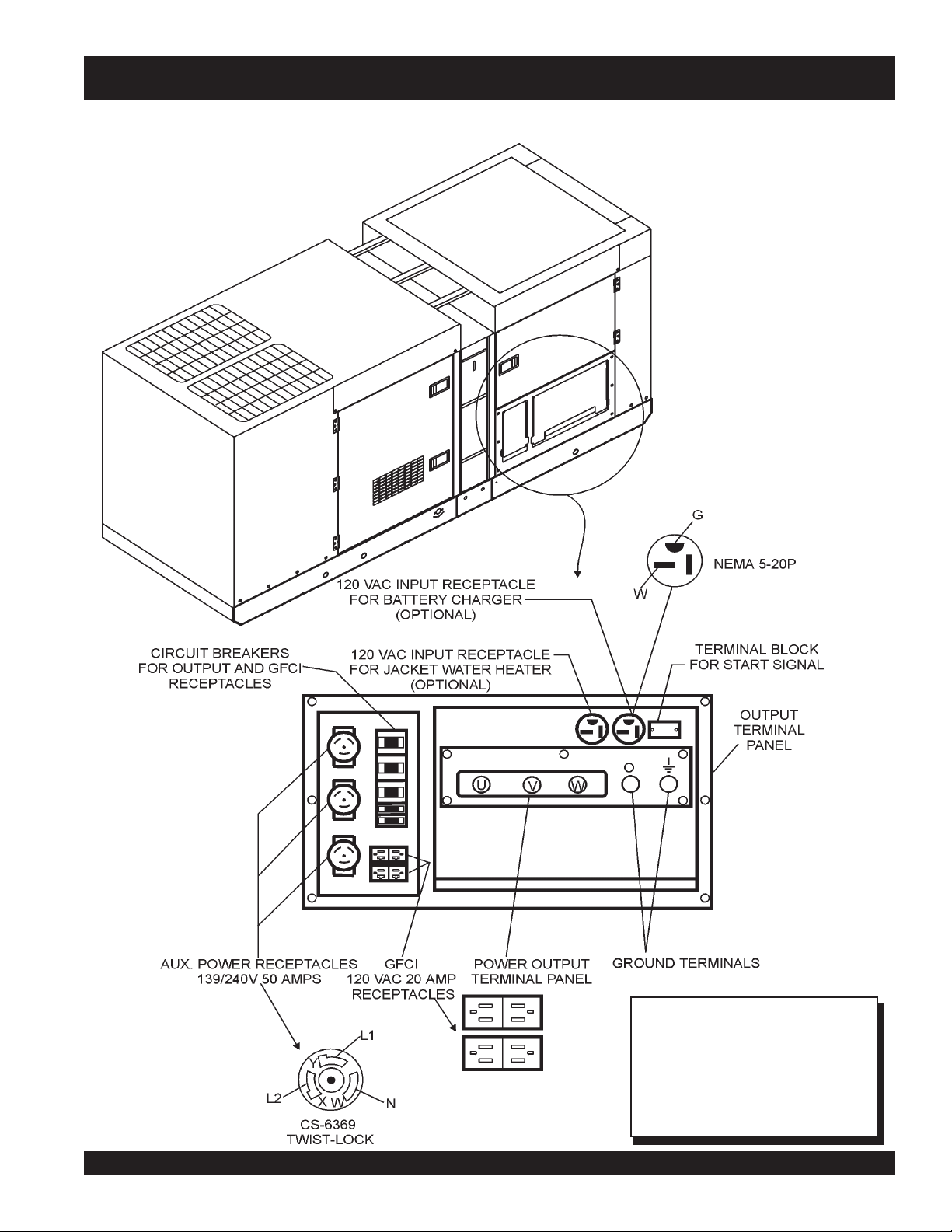
DCA-180SSK — OUTPUT TERMINAL PANEL OVERVIEW
OUTPUT TERMINAL FAMILIARIZATION
The “Output Terminal Panel” is provided with the following:
Two 120V GFCI receptacles, 20 amp
Three 240/139V output receptacles, 50 amp
Two 120V input receptacles, 20 amp (optional)
3 Load Circuit Breakers 265V @65 amps
2 Load GFCI Circuit Breakers 265V@ 20amps
Control Box
The “Control Box” is provided with the following:
Main Circuit Breaker 500 amps
Over-Current Relay
Output Terminal Panel
The Output Control Panel (See Figure 4) is located on the
right hand side (left from control panel) of the generator.
The UVW lugs are protected by a face plate cover that can
be secured in the close position by a pad lock. (See Figure
11).
Connecting Load
Loads can be connected to the generator by the UVWO Lugs or
the convenience receptacles. (See figure 13). Make sure to
read the operation manual before attempting to connect a load
to the generator.
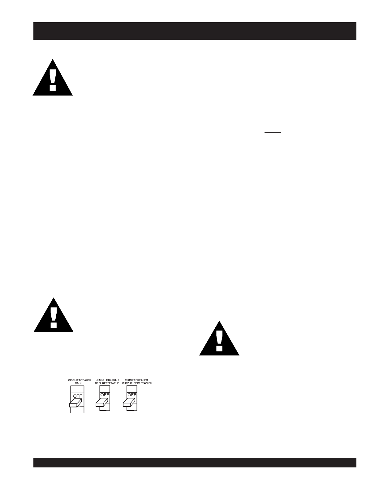
Circuit Breakers
To protect the generator from an overload, a 3-pole, 500 amp,
main
circuit breaker is provided to protect the UVW output
terminals from overload. In addition two single-pole, 20 amp
GFCI
circuit breakers are provided to protect the GFCI
receptacles from overload. Three 50 amp
have also been provided to protect the load side of the
generator from overload. Make sure to switch
breakers to the "OFF" position prior to starting the engine.
FIGURE 13. Connecting Load
load
circuit breakers
ALL
circuit
Maximum Output
FIGURE 12. Output Terminal Cover
120 Volt Receptacle
Two GFCI Duplex Nema 5-20R (120V, 20 Amp) receptacle
is provided on the output terminal. This receptacle can be
used anytime the generator is in operation. The receptacle
is controlled by the circuit breaker located on the control
panel.
Pressing the reset button resets the receptacle after being
tripped. Pressing the "Test Button" (See Figure 12) in the
center of this receptacle will check the GFCI function. The
receptacle should be tested at least once a month.
FIGURE 12. GFCI Test Button
The entire load connected to the UVWO Lugs, all four slots in
the duplex receptacles, and the must not exceed 158 kW in
standby or 144 kW in prime output.
Twist Lock Dual Voltage Receptacles
Three CS-6369 auxiliary power receptacles have been
provided to supply 208/120V. The voltage regulator knob
on the control panel may need to be used to adjust the
voltage to 208 or 416V.
Input Receptacles
Two 120 volt, 20 amp input receptacles are provided to supply
power to accessories, such as the battery charger (optional) or
jacket water heater (optional).
PAGE 34 — DCA-180SSK — PARTS AND OPERATION MANUAL — REV. #3 (06/11/09)
Page 35
DCA-180SSK — OUTPUT TERMINAL PANEL OVERVIEW
NOTE
Legs O and Ground are
considered Bonded Grounds.
FIGURE 14. Output Terminal Panel
DCA-180SSK — PARTS AND OPERATION MANUAL— REV. #3 (06/11/09) — PAGE 35
Page 36
DCA-180SSK — OUTPUT TERMINAL PANEL OVERVIEW
Output Terminal Panel Available Voltages
A wide range of voltages are available to supply load to
many different applications. Voltages may be selected by
using the voltage change-over board and how you hookup
Maximum Amps
The following table show the maximum amps the entire
generator can provide. Do not exceed the maximum amps
listed. (See Table 9)
your hard wire connection to the generator. To obtain some
of the voltages listed, fine adjustment with the Voltage
Regulator on the control panel is necessary. See the table
below (Table 8) for a list of available voltages the generator
is able to supply.
ELBALIAVASEGATLOV.8ELBAT
LEDOMKSS081ACD
EGATLOVESAHP3
)ELBATCENNOCER(
ESAHPELGNIS
)ELBATSUJDA(
TLOV802TLOV022TLOV042TLOV614TLOV044TLOV084
TLOV021TLOV721TLOV931TLOV042TLOV452TLOV772
CAUTION :
NEVER attempt to change the Voltage
Change-over board while the engine is
engaged.
:ledoMKSS081ACD
detaR
egatloV
esahPelgniS
tloV021
esahPelgniS
loV042
t
esahPeerhT
tloV042
esahPeerhT
tloV084
spmAmumixaM.9elbaT
spmAmumixaM
)eriw4(spma0.004
)eriw4(spma0.002
spma0.334
spma5.612
Over Current Relay
An over current relay is connected to the circuit breaker.
In an over current situation, both the circuit breaker and
the over current relay may trip. If the circuit breaker can
not be reset, the reset button on the over current relay
must be pressed. The over current relay is located in the
control box.
PAGE 36 — DCA-180SSK — PARTS AND OPERATION MANUAL — REV. #3 (06/11/09)
Page 37

DCA-180SSK — OUTPUT TERMINAL PANEL OVERVIEW
How to read the output terminal gauges.
The gauges and knobs on the control panel DO NOT effect
the generator output in any fashion. They are there to
simply help the operator observe how much power is being
produced at the UVWO legs.
To read the output of the W-U legs, for example, place the
AC Voltmeter Change-over switch to the W-U position and
the AC ammeter Change-over Switch to the U or W
position to read the output on the selected leg.
FIGURE 15. AC Voltmeter
Change-over switch
(Reading the W-U leg on
the output terminal panel)
FIGURE 17. AC Ammeter
Change-over Switch
(Reading the U leg on the
output terminal panel)
FIGURE 16. AC Voltmeter
Gauge
(Volt reading on W-U Lug)
FIGURE 18. AC Ammeter
(Amp reading on U lug)
DCA-180SSK — PARTS AND OPERATION MANUAL— REV. #3 (06/11/09) — PAGE 37
Page 38

DCA-180SSK — OUTPUT TERMINAL PANEL OVERVIEW
Voltage Change-over Board
The voltage change-over board changes the available
voltages of the output terminal panel UVWO lugs. The
voltage change-over board is located on the control box
behind the control panel. There are six (6) plates that can
be set into two set positions to get six different voltages.
Unless specified differently, the generator comes from the
factory in the 240V position.
240 Volt Set position
The voltage change-over board 240V set position uses all
6 plates in 6 different connection places. See figure 19
below.
Single Phase, 240 Volt
The following connection, with the voltage change-over
board set into the 240V set position (See Figure 19), can
offer SINGLE PHASE power at 240V. After hooking up
the hard wires to the lugs as shown in figure 21 below,
240V will be the voltage output.
FIGURE 21. Hard Wire Hookup for Single Phase 240V
FIGURE 19. Voltage Change-over Board 240V set position.
3 Phase, 240 Volt
The following connection, with the voltage change-over
board set into the 240V set position (See Figure 19), can
offer THREE PHASE power at 240V. After hooking up the
hard wires to the lugs as shown in figure 20 below, 240V
will be the voltage output.
Single Phase, 139 Volt
The following connection, with the voltage change-over
board set into the 240V set position (See Figure 19), can
offer SINGLE PHASE power at 139V. After hooking up
the hard wires to the lugs as shown in figure 22 below,
139V will be the voltage output.
FIGURE 20. Hard Wire Hookup for Three Phase 240V
PAGE 38 — DCA-180SSK — PARTS AND OPERATION MANUAL — REV. #3 (06/11/09)
FIGURE 22. Hard Wire Hookup for Single Phase 139V
Page 39

DCA-180SSK — OUTPUT TERMINAL PANEL OVERVIEW
480 Volt Set position
The voltage change-over board 480V set position uses all
6 plates in 3 different connection places. There are 2
plates at every position (Every plate is used). See figure
23 below.
Single Phase, 480 Volt
The following connection, with the voltage change-over
board set into the 480V set position (See Figure 23), can
offer SINGLE PHASE power at 480V. After hooking up
the hard wires to the lugs as shown in figure 25 below,
480V will be the voltage output.
FIGURE 23. Voltage Change-over Board 480V set position.
3 Phase, 480Volt
The following connection, with the voltage change-over
board set into the 480V set position (See Figure 23), can
offer THREE PHASE power at 480V. After hooking up the
hard wires to the lugs as shown in figure 24 below, 480V
will be the voltage output.
FIGURE 25. Hard Wire Hookup for Single Phase 480V
Single Phase, 277 Volt
The following connection, with the voltage change-over
board set into the 480V set position (See Figure 23), can
offer SINGLE PHASE power at 277V. After hooking up
the hard wires to the lugs as shown in figure 26 below,
277V will be the voltage output.
FIGURE 24. Hard Wire Hookup for Three Phase 480V
DCA-180SSK — PARTS AND OPERATION MANUAL— REV. #3 (06/11/09) — PAGE 39
FIGURE 26. Hard Wire Hookup for Single Phase 277V
Page 40

DCA-180SSK — INSTALLATION
Outdoor Installation
Install the generator in a location where it will not be exposed
to rain or sunshine. Make sure the generator is on secure
level ground so that it cannot slide or shift around. Also
install the generator in a manner so the exhaust will not be
discharged in the direction of nearby homes.
The installation site must be relatively free from moisture
and dust. All electrical equipment should be protected from
excessive moisture. Failure to do will result in deterioration
of the insulation and will result in short circuits and grounding.
Foreign materials such as dust, sand, lint and abrasive
materials have a tendency to cause excessive wear to the
engine parts and the alternator.
CAUTION :
Pay close attention to ventilation when
operating the generator inside tunnels and
caves. The engine exhaust contains
noxious elements. Engine exhaust must
be routed to a ventilated area.
CAUTION :
Generator Grounding
To guard against electrical shock and possible damage to
the equipment, it is important to provide a good EARTH
ground.
Article 250 (Grounding) of the National Electrical Code (NEC)
provides guide lines for proper grounding and specifies that
the cable ground shall be connected to the grounding system
of the building as close to the point of cable entry as
practical.
NEC articles 250-64(b) and 250-66 set the following
grounding requirements:
1. Use one of the following wire types to connect the
generator to earth ground.
a. Copper - 10 AWG (5.3 mm
b. Aluminum - 8 AWG (8.4 mm2) or larger.
An electric shock may happen when
vibrators are used. Pay close attention
to handling when operating vibrators and
always use rubber boots and gloves to
insulate the body from electrical shock.
2
) or larger.
2. When grounding the generator (Figure 27) connect the
ground cable between the lock washer and the nut on
Indoor Installation
Exhaust gases from diesel engines are extremely poisonous.
Whenever an engine is installed indoors the exhaust fumes
must be vented to the outside. The engine should be installed
at least two feet from any outside wall. Using an exhaust
pipe which is too long or too small can cause excessive
back pressure which will cause the engine to heat
excessively and possibly burn the valves.
the generator and tighten the nut fully. Connect the other
end of the ground cable to earth ground.
3. NEC article 250-52(c) specifies that the earth ground
rod should be buried a minimum of 8 ft. into the ground.
NOTE
When connecting the generator to
any buildings electrical system
ALWAYS consult with a licensed
electrician.
PAGE 40 — DCA-180SSK — PARTS AND OPERATION MANUAL — REV. #3 (06/11/09)
Page 41

DCA-180SSK — INSTALLATION
Figure 27. Typical Generator Grounding Application
DCA-180SSK — PARTS AND OPERATION MANUAL— REV. #3 (06/11/09) — PAGE 41
Page 42

DCA-180SSK — PRE-SETUP
General Inspection Prior to Operation
The DCA-180SSK generator has been thoroughly inspected
and accepted prior to shipment from the factory. However,
be sure to check for damaged parts or components, or loose
nuts and bolts, which could have occurred in transit.
Extension Cable
When electric power is to be provided to various tools or
loads at some distance from the generator, extension
cords are normally used. Cables should be sized to allow
Circuit Breakers
To protect the generator from an overload,
main
circuit breaker is provided to protect the UVW output
terminals from overload. In addition two single-pole, 20 amp
GFCI
circuit breakers are provided to protect the GFCI
receptacles from overload. Three 50 amp
have also been provided to protect the load side of the
generator from overload. Make sure to switch
breakers to the "OFF" position prior to starting the engine.
for distance in length and amperage so that the voltage
drop between the generator and point of use (load) is held
to a minimum. Use the Cable Selection Guide (Table 10)
as a guide for selecting proper cable size.
a 3-pole, 500 amp,
load
circuit breakers
ALL
NOTE
ALWAYS consult with a licensed
electrician for correct extension
cord wire size.
circuit
sttaWnIdaoLhtgneLelbaCelbawollAmumixaM
tnerruC
ni
serepmA
5.20
50060021.tf005.tf003.tf002.tf521
5.70090081.tf053.tf002.tf521.tf001
0100210042.tf052.tf051.tf00
5100810063.tf051.tf001.tf56
0200420084.tf521.tf57.tf05
021tA
stloV
03006.tf0001.tf006.tf573.tf052
tA
042
stloV
eriW01#eriW21#eriW41#eriW61#
1
.egatlovwolmorftlusernacegamadtnempiuqE:NOITUAC
)noitarepOesahPelgniS,zH06(noitceleSelbaC.01elbaT
PAGE 42 — DCA-180SSK — PARTS AND OPERATION MANUAL — REV. #3 (06/11/09)
Page 43

DCA-180SSK — PRE-SETUP
Lubrication Oil
Fill the engine crankcase with lubricating oil through the filler
hole, but do not overfill. Make sure the generator is level.
With the dipstick inserted all the way, but without being screw
into the filler hole, verify that the oil level is maintained
between the two notches (Figure 28) on the dipstick. See
Table 11 for proper selection of engine oil.
Fuel
Pay attention to the fuel tank capacity when replenishing
fuel. Fill the fuel tank with clean and fresh
NOT fill the tank beyond capacity.
The fuel tank cap must be closed tightly after fillin
fuel in a safety container. If the container does not have a
spout, use a funnel. Wipe up any spilled fuel immediately.
CAUTION :
Coolant
Use only drinkable tap water. If hard water or water with
many impurities is used, the inside of the engine and radiator
may become coated with deposits and cooling efficiency
will be reduced.
Figure 28. Engine Oil Dipstick
An anticorrosion additive added to the water will help prevent
deposits and corrosion in the cooling system. See the engine
When checking the engine oil, be sure to check if the oil is
clean and viscous. If the oil is not clean, drain the oil by
removing the oil drain plug, and refill with the specified amount
of oil as outlined in the Komatsu Engine Owner's Manual.
manual for further details.
diesel fuel
Never fill the fuel tank while the engine is
running or in the dark. Diesel fuel spillage
on a hot engine can cause a fire or
explosion. If diesel fuel spillage occurs,
wipe up the spilled fuel completely to
prevent fire hazards.
. DO
g. Handle
liOrotoMdednemmoceR.11elbaT
erutarepmeT
egnaR
F°32~F°401
)C°5-~C°04(
F°5~F°32
)C°51-~C°5-(
)°51-(C°5woleB03-
DCA-180SSK — PARTS AND OPERATION MANUAL— REV. #3 (06/11/09) — PAGE 43
liOepyT
03EAS
03-W01EASro02EAS
W01EASroW01EAS
Page 44

DCA-180SSK — PRE-SETUP
CAUTION :CAUTION :
CAUTION :
CAUTION :CAUTION :
When adding coolant or antifreeze to the
radiator, do not remove the radiator cap
until the unit has completely cooled.
Day-to-day addition of coolant is done from the reserve tank.
When adding coolant to the radiator, DO NOT remove the
radiator cap until the unit has completely cooled. See Table
12 for engine, radiator, and reserve tank coolant capacities.
Make sure the coolant level in the reserve tank is always
between the "H" and the "L" markings.
yticapaCtnalooC.21elbaT
rotaidaRdnaenignE)sretiL82(.laG4.7
knaTevreseR)sretiL9.1(strauQ2
Operation in Freezing Weather
When operating in freezing weather, be certain the proper
amount of antifreeze (Table 13) has been added.
Cleaning the Radiator
The engine may overheat if the radiator fins become
overloaded with dust or debris. Periodically clean the radiator
fins with compressed air. Cleaning inside the machine is
dangerous, so clean only with the engine turned off and the
battery disconnected.
Air Cleaner
Periodic cleaning/replacement is necessary. See
maintenance section for instruction to cleaning/replacing air
cleaner.
Fan Belt Tension
A slack fan belt may contribute to overheating, or to
insufficient charging of the battery. Inspect the fan belt for
damage and wear. See maintenance section on replacing
belts. To adjust tension:
1. Insert a bar between alternator and the cylinder block to
fix alternator in position. When fixing the alternator in
position, insert a wooden block between the bar and
alternator to prevent damage to the alternator.
2. Loosen bolts and nuts located on the alternator.
3. Move alternator with the bar so the deflection of the belt
is approx. 8mm.
4. Tighten the bolt and nuts to fix the alternator back to
position.
tnioPgnizeerFtnioPgnilioB
%loV
ezeerF-itnA
C°F°C°F°
0442-21-601222
0573-43-80
NOTE
When the antifreeze is mixed with
water, the antifreeze mixing ratio must
be less than 50%.
1622
The fan belt tension is proper if the fan belt bends 7 to 10
mm (Figure 29) when depressed with the thumb as shown
below.
serutarepmeTgnitarepOezeerF-itnA.31elbaT
Figure 29. Fan Belt Tension
CAUTIONCAUTION
CAUTION
CAUTIONCAUTION
:
Never place hands near the belts or fan while
the generator set is running.
PAGE 44 — DCA-180SSK — PARTS AND OPERATION MANUAL — REV. #3 (06/11/09)
Page 45

DCA-180SSK — PRE-SETUP
Battery Cable Installation
ALWAYS be sure the battery cables (Figure 30) are properly
connected to the battery terminals as shown below. The
RED
cable is connected to the positive terminal of the battery,
and the BLACK cable is connected to the negative terminal
of the battery.
Figure 30. Battery Connections
CAUTIONCAUTION
CAUTION
CAUTIONCAUTION
:
If the battery cable is connected
incorrectly, electrical damage to the
generator will occur. Pay close attention
to the polarity of the battery when
connecting the battery.
CAUTIONCAUTION
CAUTION
CAUTIONCAUTION
Wiring
Inspect the entire generator for bad or worn electrical wiring
or connections. If any wiring or connections are exposed
(insulation missing) replace wiring immediately.
Piping and Hose Connection
Inspect all piping, oil hose, and fuel hose connections for
wear and tightness. Tighten all hose clamps and check hoses
for leaks.
If any hose (fuel or oil) lines are defective replace them
immediately.
Battery
This unit is of negative ground DO NOT connect in reverse.
Always maintain battery fluid level between the specified
marks. Battery life will be shortened, if the fluid level is not
properly maintained. Add only distilled water when
replenishment is necessary.
The battery is sufficiently charged if the specific gravity of
:
Inadequate battery connections may cause
poor starting of the generator, and create
other malfunctions.
the battery fluid is 1.28 (at 68°F). If the specific gravity
When connecting battery do the following:
1. DO NOT connect the battery cables to the battery
terminals when the
the manual or auto position (ON). ALWAYS make sure
that the Off/Manual/Auto switch is in the OFF position
when connecting the battery..
2. Place a small amount of grease around both battery
terminals. This will ensure a good connection and will
help prevent corrosion around the battery terminals.
Off/Manual/Auto
switch is in either
should fall to 1.245 or lower, it indicates the battery is
discharged and needs to be recharged or replaced.
Check to see whether the battery cables are loose. Poor
contact may result in poor starting or malfunctions. Always
keep the terminals firmly tightened. Coating the terminals
with a thin film of grease will help inhibit corrosion.
DCA-180SSK — PARTS AND OPERATION MANUAL— REV. #3 (06/11/09) — PAGE 45
Page 46

DCA-180SSK — LOAD APPLICATION
Single Phase Load
CAUTION:
Always be sure to check the nameplate on the generator
and equipment to insure the wattage, amperage and
frequency requirements are satisfactorily supplied by the
generator for operating the equipment.
Generally, the wattage listed on the nameplate of the
equipment is its rated output. Equipment may require 130—
150% more wattage than the rating on the nameplate, as
An inadequate size connecting cable which cannot carry
the required load can cause a voltage drop which can burn
out the appliance or tool and overheat the cable.
the wattage is influenced by the efficiency, power factor and
starting system of the equipment.
NOTE
If wattage is not given on the
equipment's name plate, approximate
wattage may be determined by
multiplying nameplate voltage by the
nameplate amperage.
WATTS = VOLTAGE x AMPERAGE
When connecting a resistance load such as an
incandescent lamp or electric heater, a capacity of up
to the generating set’s rated output (kW) can be used.
When connecting a fluorescent or mercury lamp, a
capacity of up to the generating set’s rated output (kW)
multiplied by 0.6 can be used.
When connecting an electric drill or other power tools,
pay close attention to the required starting current
The power factor of this generator is 0.8. See Table 14
below when connecting loads.
capacity.
When connecting ordinary power tools, a capacity of up to
the generating set’s rated output (kW) multiplied by 0.8 can
daoLyBrotcaFrewoP.41elbaT
daoLfOepyTrotcaFrewoP
srotom
,sretaehcirtcelE
spmal
altnecseroulF
noitcudniesahp-elgniS
spmaltnecsednacni
yrucem,spm
,secivedcinortcelE
tnempiuqenoitacinummoc
slootrewopnommoC8.0
57.0-4.0
0.1
9.0-4.0
0.1
be used.
CAUTION:
Motors and motor-driven equipment draw
much greater current for starting than
during operation.
Before connecting this generator to any
building’s electrical system, a licensed
electrician must install an isolation
(transfer) switch. Serious injury or death
may result without this transfer switch.
Three Phase Load
When calculating the power requirements for 3-phase power
use the following equation:
PAGE 46 — DCA-180SSK — PARTS AND OPERATION MANUAL — REV. #3 (06/11/09)
NOTE
If output (kVA) is not given on the equipment
nameplate, approximate output may be
determined by multiplying voltage by
amperage by .
Page 47
DCA-180SSK — GENERATOR START-UP PROCEDURE (MANUAL)
WARNING:WARNING:
WARNING:
WARNING:WARNING:
The engine's exhaust contains harmful
emissions.
exhaust when operating inside tunnels,
excavations or buildings. Direct exhaust
away from nearby personnel.
Before Starting
Engine
1. Check the lubricating oil level prior to starting the engine.
Make sure the generator is level. The oil level must be
maintained between two notches on the dipstick.
2. When there is not enough lubricating oil, fill the crankcase
with high grade motor oil. Use a high quality detergent
oil classified CC or higher (See Table 9 on page 39).
3. Check the coolant level in the radiator and subtank.
Replenish with antifreeze as necessary. Always maintain
the coolant level between the FULL and LOW markings
on the coolant container. Be sure the radiator cap is
fastened securely.
4. Check the fuel level on the fuel gauge. If fuel is low, fill
the fuel tank with clean fresh diesel fuel. If fuel spillage
occurs, completely wipe up the spilled fuel immediately.
Before Starting
Generator and Control Panel
ALWAYS
ventilate the
CAUTION:
Jacket Water Heater and Internal Battery Charger 120
VAC Output Receptacles (OPTIONAL)
This generator is equipped with two 120 VAC, 20 amp output
receptacles located on the output terminal panel, page 35
Figure 14.
The purpose of these receptacles is to provide power via
commercial power to the jacket water heater and internal
battery charger.
These receptacles will ONLY function when commercial
power has been supplied to them (Figure 32). To apply
commercial power to these receptacles, a power cord of
adequate size will be required.
When using the generator in
to apply power to jacket water heater. However, if the
generator will be used in
idea to apply power to the jacket water heater at all times. To
apply power to the jacket water heater simply apply power
to the jacket water heater receptacle via commercial power
using an power cord of adequate size.
If the generator will be used daily, the battery should normally
not require charging. If the generator will be idle (not used)
for long periods of time, apply power to the battery charger
receptacle via commercial power using an power cord of
adequate size.
When connecting the generator to a isolation (transfer)
switch, ALWAYS have power applied to the generator's
internal battery charger. This will ensure that the engine will
not fail due to a dead battery.
hot
climates there is no reason
cold
climates it is always a good
NEVER start the engine with the
main, GFCI
in the ON position.
1. Be sure to disconnect the electrical load and switch the
main, load
the “OFF” position prior to starting the engine.
and
G.F.C.I.
Figure 31. Main, GFCI and
Load Circuit Breakers
DCA-180SSK — PARTS AND OPERATION MANUAL— REV. #3 (06/11/09) — PAGE 47
or
load
circuit breakers
circuit breakers (Figure 31) to
CAUTION:
ALWAYS have power applied to the
generator's internal battery charger when
connecting the generator to a isolation
(transfer) switch. Remember before
connecting this generator to any buildings
electrical system, have a
perform the installation of the transfer switch.
licensed
electrician
Page 48

DCA-180SSK — GENERATOR START-UP PROCEDURE
Figure 32. 120 VAC Accessory Receptacle/Cable
2. Once it is determined if commercial power is required,
connect the load to the UVW terminals as shown in
3. Connect the negative battery cable (BLACK) to the
negative post on the battery (Figure 34).
Figure 33. These terminals can be found on the output
terminal panel, see page 35, Figure 14. To gain access
to the output terminals lift the UVW cover. Make sure to
tighten terminal nuts securely to prevent load wires from
slipping out.
Figure 33. UVW Terminal Lugs (Load)
NEGATIVE
POSTIVE
BATTERY
Figure 34. Battery Connections
PAGE 48 — DCA-180SSK — PARTS AND OPERATION MANUAL — REV. #3 (06/11/09)
Page 49

DCA-180SSK — GENERATOR START-UP PROCEDURE (MANUAL)
4. Close all engine enclosure doors (Figure 35).
Figure 35. Engine Enclosure Doors
5. Set the battery switch to “ON” (Figure 36).
8. Place the Off/Manual/Auto switch (Figure 40) in the
MANUAL position (down). Observe that the engine begins
to crank.
Figure 40. Off/Manual/Auto Switch (Manual)
9. After engine starts, verify that the "Engine Running"
status LED (Figure 41) on the Microprocessor Engine
Control Module (MPEC) display is "ON" (lit).
Figure 36. Battery ON/OFF Switch
6. Make sure the engine switch is on “LOW” (Figure 37).
Figure 41. MPEC Engine Running Status LED
10. If the generator is equipped with a ignition switch, turn
the key to “Start” position (Figure 42). Once the engine
starts, release the key to the “on” position.
Figure 37. Engine Speed Switch
7. When starting the generator in COLD weather conditions,
press and hold the engine preheat button (Figure 38)
until the preheat lamp (Figure 39) is lit (ON).
Figure 38. Engine Pre-Heat Button
Figure 42. Engine Ignition Switch
Figure 39. Engine Pre-Heat Lamp
DCA-180SSK — PARTS AND OPERATION MANUAL— REV. #3 (06/11/09) — PAGE 49
Page 50

DCA-180SSK — GENERATOR START-UP PROCEDURE (MANUAL)
WATER
TEMP
11. The generator's frequency meter (Figure 43) displays
the 60 cycle output frequency in HERTZ.
14. The engine oil pressure gauge (Figure 47) will indicate
the oil pressure (kg/ cm2) of the engine. Under normal
operating conditions the oil pressure should be
approximately 25 psi.
Figure 43. Frequency Meter (Hz)
12. The generator's voltage meter (Figure 44) displays the
120 VAC in VOLTS. If the voltage is not within the
specified frequency tolerance, use the voltage
adjustment control knob (Figure 45) to increase or
decrease the desired voltage.
15. The coolant temperature gauge (Figure 48) will indicate
the coolant temperature. Under normal operating
conditions the coolant temperature should be between
105 and 215 degrees Fahrenheit (Green Zone).
Figure 47. Oil Pressure Gauge
Figure 44. Voltage Meter (Volts)
Figure 48. Coolant Temperature Gauge
Figure 45. Voltage Adjust Control Knob
16. Set the engine speed switch (Figure 49) to low to idle
13. The ammeter (Figure 46) will indicate zero amps with no
engine, set to high when a load is being applied.
load applied. When a load is applied, this meter will
indicate the amount of current that the load is drawing
from the generator’s alternator.
40
20
0
60
75
A
Figure 49. Engine Speed Switch
Figure 46. Ammeter (No Load)
PAGE 50 — DCA-180SSK — PARTS AND OPERATION MANUAL — REV. #3 (06/11/09)
Page 51

DCA-180SSK — GENERATOR START-UP PROCEDURE (MANUAL)
17. The tachometer (Figure 50) will indicate the speed of
the engine when the generator is operating. Under normal
operating conditions this speed should be approximately
1800 RPM’s.
Figure 50. Engine Tachometer
18. If the engine speed is too high or low, use the high idle
adjust trimmer (Figure 51) located on the control box to
21. Observe he generator's ammeter (Figure 53) and verify
that it reads the anticipated amount of current with
respect to the load. Remember the ammeter will only
display a current reading if the load is in use.
22. The generator will run until manually stopped or an
abnormal condition occurs.
adjust the rated speed of the engine
Figure 51. Engine Idle Adjust Trimmer
40
20
0
60
75
A
Figure 53. Ammeter (Load)
19. After the engine has been running for a few minutes,
look at the status LED’S on the "MPEC" display (Figure
41) and check it for any abnormal conditions. If any
abnormal conditions exist, take corrective action to solve
the problem.
20. If there are no abnormal problems shown on the “MPEC"
LED display, turn the MAIN, GFCI and LOAD circuit
breakers to their ON position (Figure 52).
Figure 52. Main and GFCI Circuit Breakers
DCA-180SSK — PARTS AND OPERATION MANUAL— REV. #3 (06/11/09) — PAGE 51
Page 52

DCA-180SSK — GENERATOR START-UP PROCEDURE (AUTO)
CAUTION:
Before connecting this generator to any
building’s electrical system, a licensed
electrician must install an isolation
(transfer) switch. Serious
may result without this transfer switch.
injury
or
death
CAUTION:
When connecting the generator to a
isolation (transfer) switch, ALWAYS have
power applied to the generator's internal
battery charger. This will ensure that the
engine will not fail due to a dead battery.
Starting the generator in the "AUTO" mode is similar to
starting the generator in the "MANUAL" mode, with a few
exceptions.
When starting generator in Auto mode use the "Manual Startup" procedure except where noted (see below).
1. Perform steps 1 through 8 (See page 47-49) as outlined
in the manual starting procedure.
2. Apply commercial power to the internal battery charger
receptacle (to ensure good starting) via commercial
power. An external power cord will be required.
3. Apply commercial power to the jacket water heater
receptacle (not necessary for warm climates) via
commercial power. An external power cord will be
required.
4. Place the Off/Manual/Auto switch (Figure 54) in the
AUTO position (up).
CAUTION:
When running the generator in the AUTO
mode, remember the generator can start
up at any time without warning. NEVER
attempt to perform any maintenance when
the generator is in the auto mode.
5. Continue to follow the steps outline in the manual start-
Figure 54. Off/Manual Auto Switch
(AUTO)
up procedure (start at step 11, page 50).
PAGE 52 — DCA-180SSK — PARTS AND OPERATION MANUAL — REV. #3 (06/11/09)
Page 53

DCA-180SSK — GENERATOR SHUTDOWN PROCEDURE
Engine Shutdown
To shutdown the generator use the following procedure:
1. Place both the MAIN, GFCI and LOAD circuit breakers
to the "OFF position".
2. Set the engine speed switch (Figure 55) to the idle (low)
position.
Figure 55. Engine Speed Switch
3. Let the engine cool by running it for 3-5 minutes with no
load applied.
4. Place the Off/Manual/Auto Switch (Figure 56) in the "OFF/
RESET" position
Figure 56. Off/Manual Auto Switch (OFF)
Emergency Stop
1. To stop the engine in the event of an emergency, PUSH
the emergency stop button ( Figure 58) inward. This button
is located on the generator's engine operating panel,
see page 32, Figure 10.
CAUTIONCAUTION
CAUTION
CAUTIONCAUTION
Figure 58. Emergency Stop Button
:
NEVER stop the engine suddenly except
in an emergency. DO NOT use the
emergency stop switch a as method of
shutting down the engine. This switch is
ONLY to be used in the event of an
emergency.
5. Verify that the "Engine Running" status LED (Figure 57)
on the Microprocessor Engine Control Module (MPEC)
display is "OFF" (not lit).
Figure 57. MPEC Engine Running
Status LED (OFF)
6. Remove the load from the UVWO terminal strip (Figure 14
on page 35).
DCA-180SSK — PARTS AND OPERATION MANUAL— REV. #3 (06/11/09) — PAGE 53
Page 54

DCA-180SSK — MAINTENANCE
General Inspection
Prior to each use, the generating set should be cleaned and
inspected for deficiencies. Check for loose, missing or
damaged nuts, bolts or other fasteners. Also check for fuel
or oil leaks.
Air Cleaner
Every 50 hours: If dust indicator is red, clean the air cleaner
element.
Outer Element:
1. Loosen wing bolt, remove dust cup, then remove wing
nut and take out element.
2. Clean the inside of the body and cover using a damp
cloth.
3. Blow dry with compressed air (0.69Mpa {7kgf.cm
99.4 PSI} maximum against the side of the element
along the pleats. Then blow dry against outside along
the pleats, then against inside again.
4. Remove one seal each time the element is cleaned.
5. Replace the outer element after cleaning it 6 times or
after one year. Replace the outer element if indicator is
red even after cleaning it.
6. Check the inner cylinder element clamping nut for
looseness, and retighten if necessary.
7. If seal washer is damaged or the threads of wing nut are
damaged, replace.
8. Remove evacuator valve and clean it with compressed
air. Reinstall.
Inner element (if equipped)
1. Remove the cover and outer element, then remove the
inner element.
2. Cover the air connector opening (outer side) with clean
cloth or cloth tape.
3. Clean the inside of the body. Remove air connector
opening protection.
4. Install a new inner cylinder element to the cylinder and
tighten the nut.
5. Install element.
6. After replacing the element, press the button of the dust
indicator to return the red piston to its original position.
Fuel Addition
Add diesel fuel (the grade may vary according to season
and locations). Always pour through the mesh filter.
Removing Water from the Tank
After prolonged use, water and other impurities accumulate
in the bottom of the tank. Occasionally remove the drain
cock and drain the contents. During cold weather, the greater
the empty volume inside the tank, the easier it is for water to
condense. This can be reduced by always keeping the tank
as full as possible.
Air Removal
If air enters the fuel injection system of a diesel engine,
starting becomes impossible. After running out of fuel, or
2
after disassembling the fuel system, bleed the system
,
according to the following procedure.
To restart after running out of fuel, turn the key switch to the
“START” position for 15-30 seconds. Try again, if needed.
This unit is equipped with an automatic air bleeding system.
Service Daily
If engine is operating in very dusty and dry grass conditions,
a clogged air cleaner will result in high fuel consumption,
loss of power and excessive carbon buildup in the
combustion chamber.
Cleaning the Fuel Strainer
Clean the fuel strainer if it contains dust or water. Remove
dust or water in the strainer cap and wash it in diesel. Securely
fasten the fuel strainer cap so that fuel will not leak. Check
the fuel strainer every 200 hours of operation or once a month.
Check Oil Level
Check the crankcase oil level prior to each use, or when the
fuel tank is filled. Insufficient oil may cause severe damage
to the engine. Make sure the generator is level. The oil level
must be between the two notches on the dipstick as shown
in Figure 28, page 43.
Flushing Out Radiator and Changing Coolant
1. Stop the engine and allow to cool. Tighten valve of the
corrosion resistor (if equipped).
2. Turn water filer cap slowly and remove it.
3. Prepare a container to catch the coolant, then open drain
plug of the radiator or heat exchanger and drain plug of
the engine, and drain the coolant.
4. After draining the coolant, close drain plugs and fill with
tap water.
PAGE 54 — DCA-180SSK — PARTS AND OPERATION MANUAL — REV. #3 (06/11/09)
Page 55

DCA-180SSK — MAINTENANCE
5. When the water level is near the mouth of the water
filler, open drain plugs and start the engine, and run at
low idling. Keep the engine running at low idling and
flush the radiator for about 10 minutes.
6. Adjust the flow of the water flowing in and draining out to
ensure that the radiator is always full during the flushing
operation, While flushing water through the system,
watch carefully the water inlet hose does not come out
of the radiator filler port.
7. After flushing, stop the engine, open drain plug and drain
the water, then close drain plugs.
8. After draining the water, flush the system with a flushing
agent. See instructions on flushing agent label.
9. After flushing, open drain plugs and drain out all the
water, then close drain plugs and add tap water so the
water level is near the mouth of the water filler.
10. When the water level is near the mouth of the water
filler, open drain plugs and start the engine, run at low
idling and continue to flush the system until clean water
comes out. Adjust the flow of the water flowing in and
draining out to ensure the radiator is always full during
the flushing operation.
11. When clean water comes out, stop the engine, drain all
the water, then close drain plugs.
Changing Oil
1. Make sure the oil is cool before changing.
2. Set a container directly under the drain plug of the oil
pan. Loosen the drain plug slowly.
3. Check the drained oil for excessive metal particles or
foreign material. Contact the distributor if there is metal
particles or foreign material.
4. Using a filter wrench, turn filter cartridge to the left to
remove it. If the filter cartridge is filled with a large
amount of oil, wait 10 minutes or so before removing.
Make sure there is no old gasket stuck on the filter holder.
5. Tighten drain plug. Clean the filter holder, fill the new
filter cartridge with clean engine oil, coat the packing
and thread of the new filter cartridge with engine oil,
then install it to the filter holder. Tighten until the gasket
surface contacts the seal surface of the filter holder,
then tighten it a further 3/4 to 1 turn.
6. Add engine oil through oil filler until the oil level is between
the H and L marks on the dipstick.
7. Run the engine at idling for a short time, then stop the
engine. Recheck the oil level and fill as necessary.
Replacing fuel filter
1. Set the container under the filter cartridge to catch fuel.
12. Remove the corrosion resistor (if equipped) and open
valve.
13. Supply water until it flows over the water filler.
14. Drain the water inside reserve tank, clean the inside of
the reserve tank, then fill with coolant/water mixture to
between the full and low lines.
15. Stop the engine, wait for 3 minutes, add tap water until
the water level reaches near the water filer port, then
tighten the radiator cap.
Check Electric Heater (If equipped)
Before starting in cold weather (once a year), please contact
your Komatsu distributor for inspection. Remove electric
heater from the engine intake manifold and check for
disconnections or dirt. When checking or installing the electric
heater, replace the gasket with a new part.
DCA-180SSK — PARTS AND OPERATION MANUAL— REV. #3 (06/11/09) — PAGE 55
2. Using a filter wrench, turn the filter cartridge to the left
to remove it.
3. Clean the filter holder, fill the new filter cartridge with
fuel, coat the packing surface of the filter cartridge with
engine oil, then install the cartridge to the filter holder.
4. When installing, tighten until the packing surface
contacts the seal surface of the filter holder then tighten
a further 2/3 of a turn. If the filter cartridge is tighten too
much, the packing will be damaged and will cause fuel
leakage. Fuel leakage will occur if the filter cartridge is
not tightened enough. Always tighten to the correct
angle.
5. After replacing filter cartridge, loosen air bleed plug.
6. Loosen the knob of feed pump, and pump it up and down
until no bubbles come our with the fuel from air bleed
plug.
Page 56

DCA-180SSK — MAINTENANCE
7. After bleeding the air, tighten air bleed plug, then push in
the knob of feed pump and lock it in position.
8. Replace Corrosion resistor cartridge (if equipped)
9. Screw in valves at the top of the corrosion resistor.
10. Using a filter wrench, turn the cartridge to the left to
remove it.
11. Coat the seal surface of the new cartridge with engine
oil and install it to the filter holder.
12. Tighten until he packing surface contacts the seal
surface of the filter holder, then tighten a further 2/3 of a
turn.
13. Open valves.
Cleaning breather element
1. Loosen the clamp, then remove the hose and take out
breather. Wipe off the dirt around the breather. Check
the O-ring, and replace if necessary.
2. Wash the breather in diesel fuel or flushing oil, blow dry
with compressed air, then reinstall it.
3. Inspect the hose and if there is any deteriorated oil stuck
inside the hose. Replace hose if necessary.
Greasing
Using a grease pump, grease the fan hub (1 place) and
tension pulley (2 places).
Generator Storage
For storage of the generator for over 30 days, the following
is required:
Drain the fuel tank completely, lubricate and change oil.
Disconnect the negative terminals of the battery and
cover it, or remove it from the machine and store it
separately.
If the ambient temperature is expected to drop below
0oC, add antifreeze to the radiator.
Removal from long term storage:
Apply oil to the engine valve and rocker arms, and
examine the operating condition of the valves.
remove the oil filler pipe from the turborcharger oil inlet
port, add 0.5-1L (0.13-0.26gal) of oil to the turbocharger,
reinstall the oil filler pipe.
Change the oil in engine oil pan.
Replace all the filters.
Flush the inside of the cooling system.
Drain the water from the fuel tank and bleed the air from
the fuel system.
If the engine has not been started for more than one
year, contact your Komatsu distributor to have engine
overhauled.
PAGE 56 — DCA-180SSK — PARTS AND OPERATION MANUAL — REV. #3 (06/11/09)
Page 57

DCA-180SSK — MAINTENANCE
.51ELBAT
ECNANETNIAM/NOITCEPSNI
srH01
YLIAD
srH052 srH005 srH0001
sleveLdiulFenignEkcehC X
renaelCriAkcehC X
leveLdicAyrettaBkcehC X
noitidnoCtleBnaFkcehC X
skaeLrofkcehC X
straPfogninesooLrofkcehC X
)elbacilppafi(rotarapeSretaWkcehC X
1
*retliFdnaliOenignEecalpeR
X
retliFriAnaelC X
ENIGNE
knaTleuFfomottoBniarD X
edistuOdnaedisnI,tinUnaelC X
2
*retliFleuFegnahC
3
*tnemelErotarapeSretaWecalpeR
)X( X
tnalooCkcehCdnarotaidaRnaelC
X
X
leveLnoitcetorP
tnemelEretliFriAecalpeR X
rotsiseRnoisorroCegnahC X
spmalCdnasesoHllakcehC X
knaTleuFfoedisnInaelC X
ROTARENEG
*
*
*
smhoM3
1
2
3
revOecnatsiseRnoitalusnIerusaeM
.ylnoemittsrif,sruoH052taretlifleufecalpeR
."retliFrotarapeSretaW"metiehtotrefeR
X
.ylnoemittsrif,sruoh001taretliffnalioenigneecalpeR
DCA-180SSK — PARTS AND OPERATION MANUAL— REV. #3 (06/11/09) — PAGE 57
Page 58

DCA-180SSK — GENERATOR WIRING DIAGRAM
PAGE 58 — DCA-180SSK — PARTS AND OPERATION MANUAL — REV. #3 (06/11/09)
Page 59

DCA-180SSK — ENGINE WIRING DIAGRAM
DCA-180SSK — PARTS AND OPERATION MANUAL— REV. #3 (06/11/09) — PAGE 59
Page 60

DCA-180SSK — TROUBLESHOOTING (ENGINE)
Practically all breakdowns can be prevented by proper
handling and maintenance inspections, but in the event of a
breakdown, please take a remedial action following the
diagnosis based on the Engine Troubleshooting (Table 16)
information shown below and on the proceeding page. If the
problem cannot be remedied, consult our company's
business office or service plant.
MOTPMYS MELBORPELBISSOP NOITULOS
?leufoN .leufhsinelpeR
?metsysleufehtniriA .metsysdeelB
?metsysleufehtniretaW .knatleufmorfretawevomeR
?deggolcepipleuF .epipleufnaelC
?deggolcretlifleuF .retlifleufegnahcronaelC
ytisocsivhgihylevissecxE
?erutarepmet
?rebmun
woltalioenigneroleuffo
enatecwolhtiwleuF
GNITOOHSELBUORTENIGNE.61ELBAT
.lioenigneroleufdeificepsehtesU
.leufdeificepsehtesU
esooloteudkaelleuF
?tungniniaterepipnoitcejni
.tratstonseodenignE
pmupnoitcejnI
?gninoitcnuflam
?gniraebrorenil
?rednilyc
?gnimitnoitcejnitcerrocnI .tsujdA
?nrowtfahsmacleuF .ecalpeR
?deggolcelzzonnoitcejnI .elzzonnoitcejninaelC
,tfahsknarcfoeruzieS
rednilyc,notsip,tfahsmac
morfkaelnoisserpmoC
?gnimitevlavreporpmI .raeggnimitecalperrotcerroC
?nrowrenildnagnirnotsiP .ecalpeR
?ecnaraelcevlavevissecxE .tsujdA
?gninoitcnuflamretratS .ecalperroriapeR
.tunnethgiT
.ecalperroriapeR
.ecalperroriapeR
wolg,tlobdaehrednilycnethgit,teksagdaehecalpeR
.redlohelzzondnagulp
.nurtonseodretratS
?detcennocsidgniriW .gniriwtcennoC
PAGE 60 — DCA-180SSK — PARTS AND OPERATION MANUAL — REV. #3 (06/11/09)
Page 61

DCA-180SSK — TROUBLESHOOTING (ENGINE)
MOTPMYS MELBORPELBISSOP NOITULOS
?ytridrodeggolcretlifleuF .egnahcronaelC
?deggolcrenaelcriA .egnahcronaelC
)DEUNITNOC(GNITOOHSELBUORTENIGNE.61ELBAT
esooloteudkaelleuF
?tungniniaterepipnoitcejni
pmupnoitcejnI
?gninoitcnuflam
.tunnethgiT
.ecalperroriapeR
sinoituloverenignE
.htoomston
?erusserp
?deggolc
?deggolc
eulbroetihwrehtiE
sisagtsuahxe
?kcutsro
.devresbo
?daolrevO .daolehtnesseL
gninepoelzzontcerrocnI
rokcutselzzonnoitcejnI
epipwolfrevoleuF
?gninoitcnuflamronrevoG .riapeR
?lioenigneevissecxE .leveldeificepsehtotecudeR
nrowrenildnagnirnotsiP
?gnimitnoitcejnitcerrocnI .tsujdA
?noisserpmoctneicifeD .ecnaraelcpottsujdA
.tsujdA
.ecalperroriapeR
.naelC
.ecalperroriapeR
?desuleufedargwoL .leufdeificepsehtesU
kradrokcalbrehtiE
sisagtsuahxeyarg
?deggolcretlifleuF .egnahcronaelC
.devresbo
?deggolcrenaelcriA .egnahcronaelC
?noitcejnielzzontneicifeD .elzzonehtecalperroriapeR
?gnimitnoitcejnitcerrocnI .tsujdA
strapgnivoms'enignE
?gniziesebotmees
.tuptuotneicifeD
?noitcejnileufnevenU .pmupnoitcejniehtecalperroriapeR
?noitcejnielzzontneicifeD .elzzonehtecalperroriapeR
?kaelnoisserpmoC
DCA-180SSK — PARTS AND OPERATION MANUAL— REV. #3 (06/11/09) — PAGE 61
.ecalperroriapeR
.redlohelzzondnagulp
wolg,tlobdaehrednilycnethgit,teksagdaehecalpeR
Page 62

DCA-180SSK — TROUBLESHOOTING (GENERATOR/ENGINE)
Practically all generator breakdowns can be prevented by
proper handling and maintenance inspections, but in the event
of a breakdown, please take a remedial action following the
diagnosed based on the Generator Troubleshooting (Table
17) and the MPEC troubleshooting (Table 18) information
shown . If the problem cannot be remedied, consult our
company's business office or service plant.
MOTPMYSMELBORPELBISSOPNOITULOS
?yrettabdaeD.yrettabecalpeR
dnatratsotsliafenignE
.detatortonseodretrats
dnatratsotsliafenignE
.setatorretrats
C.ecalperronaelC
tasniamerdnastratsenignE
.deepswol
?leufoN.leufddA
?gniriwevitcefeD.gniriwkcehC
?hctiwsretratsevitcefeD.hctiwseca
?tuodenrub5FesuF.esufecalpeR
?tiucrictaeh-erpnekorB.tiucrictaeh-
?reniartsleufdeggol
?renaelcriadeggolC.ecalperronaelC
?gniriwdetcennocsiD.gniriwriaperdnakcehC
GNITOOHSELBUORTROTARENEG&ENIGNE.71ELBAT
lpeR
erpkcehC
CAnitneserpegatlovoN
?ecruosrewop
enignE
.ecruosrewop
.desuebtonnac
ondnasesirdeeps
CAnitneserpsiegatlov
CAdnasesirdeepsenignE
rowolootsiegatlovrewop
dnasesirdeepsenignE
.noosootsegrahcsidyrettab
dnasesirdeepsenignE
.dedaolrevosmeesenigne
tcefeD.rotorecalpeR
?gnidniw
cefeD.rotalugerecalpeR
?rotorevi
?retemtlovevitcefeD.retemtlovecalpeR
?gniriwdetcennocsiD.gniriwriaperdnakcehC
itiucric-trohsreyaL
?)rotcetorp(
utamraniseriw
?gniriwevitcefeD.gniriwecalperroriapeR
otanretlaevitcefeD.rotanretlaecalperroriapeR
?r
erutamran
rekaerbtiucricevitcefeD
nekorb,tiucric-trohsreyaL
?gnidniwer
?rotalugerenigneevit
?gniraebrotanretladegamaD.sgniraebrotanretlaecalpeR
.)1ER(reifitcerecalpeR
.erutamraecalpeR
.)rotcetorp(rekaerbtiucricecalpeR
.erutamraecalperroriapeR
PAGE 62 — DCA-180SSK — PARTS AND OPERATION MANUAL — REV. #3 (06/11/09)
Page 63

DCA-180SSK — TROUBLESHOOTING (MPEC)
notpmySesuaCelbissoPnoituloS
?levelliowoL.levelliolliF
GNITOOHSELBUORTCEPM.81ELBAT
erusserpliowoL
.nosithgil
?detrohseriW.eriwriaper/tcepsnI
?leveltnaloocwoL.leveltnalooclliF
leveltnaloocwoL
.nosithgil
?rotaidar
?neposrooD.sroodesolC
tnaloochgiH
sithgilerutrepmet
.no
katniriA.sekatniriallaraelC
?eruliaftinugnidneS.tinugnidnesecalpeR
?egatlovyrettabwoL.yrettabegrahc/
ctonsiwolfriA
?gnikaeltsuahxE .trapytluafrosteks
?eruliaftatsomrehT.tatsomrehtecalpeR
?dekcolbe
?eruliaftinugnidneserusserpliO .tinugnidneserusserplio
?CEPMninoitnuflamyaledemiT.relaedotrefeR
?tcerrocninoisnettlebnaF.tlebnafecalper/nethgiT
hguorhtnoitalucri
?dedaolrevogniebrotareneG.daolecuder/kcehC
?eruliafhctiwserutarepmeT.hctiwserutarepmetecalpeR
ecalpeR
ecalpeR
.llirgrotaidarriaper/naelC
agriaper/ecalpeR
sithgilknarcrevO
.no
sithgildeepsrevO
.no
UPMfossoL
.noro)s(thgil
lrooN.levelleuflliF
?leuFwo
?detarbilacebotsdeenCEPM.relaedotrefeR
?hgihootdeepsenigneMPR.MPRts
?detsujdaebotsdeenrotautcaronrevoG.rotautcaronrevogtsujdA
ebotsdeenrellortnocronrevoG
?detsujda
?detarbilacebotsdeenCEPM.relaedotrefeR
citengaM.pukcipcitengamtsujdA
?ytridpukcipcitengaM.pukcipcitengamnaelC
?tnemtsujdafotuopukcip
ujdA
ortnocronrevogtsujdA
.rell
DCA-180SSK — PARTS AND OPERATION MANUAL— REV. #3 (06/11/09) — PAGE 63
Page 64

EXPLANATION OF CODE IN REMARKS COLUMN
How to read the marks and remarks used in this parts
book.
Items Found In the “Remarks” Column
Serial Numbers-Where indicated, this indicates a serial
number range (inclusive) where a particular part is used.
Model Number-Where indicated, this shows that the
corresponding part is utilized only with this specific model
number or model number variant.
Items Found In the “Items Number” Column
All parts with same symbol in the number column,
belong to the same assembly or kit.
Note: If more than one of the same reference number is listed, the
last one listed indicates newest (or latest) part available.
, #, +, %, or ■,
*
PAGE 64 — DCA-180SSK — PARTS AND OPERATION MANUAL — REV. #3 (06/11/09)
Page 65

DCA-180SSK — SUGGESTED SPARE PARTS
DCA-180SSK W/KOMATSU SA6D108E-2
DIESEL ENGINE
1 OF 5 UNITS
Qty. P/N Description
1 ......... 0601808262 ..... CIRCUIT BREAKER
1 ......... 0601820625 ..... AUTOMATIC VOLTAGE REGULATOR
1 ......... 0601840073 ..... RHEOSTAT VOLTAGE REGULATOR
1 ......... 0601840121 ..... KNOB RHEOSTAT
1 ......... 0602014594 ..... RADIATOR HOSE
1 ......... 0602013977 ..... RADIATOR HOSE
1 ......... 0602014645 ..... RADIATOR HOSE
5 ......... 0602041147 ..... OIL FILTER
5 ......... 0602042146 ..... FUEL FILTER
5 ......... 0602046333 ..... AIR ELEMENT
1 ......... 0602122251 ..... UNIT OIL PRESSURE
1 ......... 0602123250 ..... UNIT WATER PRESSURE
1 ......... 0601810244 ..... BULB
1 ......... 0602102047 ..... BULB
1 ......... 0601808507 ..... TRANSDUCER WATT METER
1 ......... 412121761 ....... FAN BELT
DCA-180SSK — PARTS AND OPERATION MANUAL— REV. #3 (06/11/09) — PAGE 65
Page 66

GENERATOR ASSY.
DCA-180SSK — GENERATOR ASSY.
PAGE 66 — DCA-180SSK — PARTS AND OPERATION MANUAL — REV. #3 (06/11/09)
Page 67

DCA-180SSK — GENERATOR ASSY.
GENERATOR ASSY.
NO PART NO PART NAME QTY. REMARKS
1 C0110100102 ROTOR ASSEMBLY ........................ 1 .................. INCLUDE ITEMS W/*
2* 0071906314 BEARING ...................................... 1 .................. 6314 DDU C3
3* C1112500004 BEARING FLANGE 1
4* 0601823282 RECTIFIER ................................... 1 .................. RM50TC-24
5* 0018205020 HEX. CAP SCREW 2
6* 0040005000 LOCK WASHER 2
7* 0041205000 PLAIN WASHER 2
8* 0601000209 BALANCING WEIGHT KIT 1
9* 0601842334 RESISTOR ......................................1 .................. SMRK 80W 100kS
10* 0042616000 LOCK WASHER 8
11* 8171070002 FAN 1
12* 8171611003 COUPLING DISK 9
13* C1164200004 WASHER, COUPLING HUB 1
14* 81710-15003 BALANCING PLATE 1
15 0012116045 HEX. HEAD BOLT 8
16 06050-00012 RUBBER SUSPENSION 2
17* 0012112040 HEX. HEAD BOLT 8
18 8301614003 COUPLING RING 1
19 0012112035 HEX. HEAD BOLT 8
20 C1154400004 COVER, BEARING 1
21 0010106060 HEX. HEAD BOLT 4
22 0040006000 LOCK WASHER 4
23 0041206000 PLAIN WASHER 5
24 C1154300004 GASKET, BEARING 1
25 0017106016 HEX. HEAD BOLT 8
26 C1154400103 SUCTION COVER 1
27 0017112045 HEX. HEAD BOLT 6
28 C1154000002 END BRACKET 1
29 0012110065 HEX. HEAD BOLT 4
30 0042610000 LOCK WASHER 4
31 0041210000 PLAIN WASHER 4
32 C1138000003 FIELD ASS’Y EXCITER 1
33 C0130100003 STATOR ASSEMBLY ...................... 1 .................. INCLUDE ITEMS W/#
34# 0845041804 GROMMET 2
35# 0601850144 GROMMET 1
36# 0012112035 HEX. HEAD BOLT 12
37 0042512000 LOCK WASHER 27
38 C0132300003 COVER, FAN 1
39 0010106030 HEX. HEAD BOLT 1
40 0040020000 LOCK WASHER 4
41 0030020000 HEX. NUT 4
42* 0042512000 LOCK WASHER 1
42 0605000012 RUBBER SUSPENSION 2
EA1013
DCA-180SSK — PARTS AND OPERATION MANUAL— REV. #3 (06/11/09) — PAGE 67
Page 68

CONTROL PANEL ASSY.
DCA-180SSK — CONTROL PANEL ASSY.
PAGE 68 — DCA-180SSK — PARTS AND OPERATION MANUAL — REV. #3 (06/11/09)
Page 69

DCA-180SSK — CONTROL PANEL ASSY.
CONTROL PANEL ASSY.
NO PART NO PART NAME QTY. REMARKS
1 C0224001203 CONTROL PANEL 1
2 0605011211 PIN 2
3 0601801040 CHANGE-OVER SW., AMMETER .................... 1 ...... SL-2 AS
4 0601801041 CHANGE-OVER SW., VOLTMETER ................. 1 ...... SL-2 VS
5* 0601810261 BULB ................................................................ 1 ...... CT-13W
6 0601810072 PILOT LAMP .................................................... 1 ...... LP-132DC 220V
INCLUDES ITEM W/*
7 0080200007 SNAP RING 2
8 0041208000 PLAIN WASHER 2
9 0040008000 LOCK WASHER 2
10 C9221100004 HEX. HEAD BOLT 2
11 0207004000 HEX. NUT 2
12 0601810161 PANEL LIGHT .................................................. 1 ...... CV325070 INCLUDES ITEM W/#
13# 0601810214 BULB 1
14 0601806887 AC VOLTMETER ............................................. 1 ...... RSR-80 0~600V
15 0601806967 AC AMMETER ................................................ 1 ...... RSS-80 0~300A,0~600A
16 0601807622 FREQUENCY METER ..................................... 1 ...... RSC-80F 220V 45~65Hz
17 0601840121 KNOB 1
18 0601830710 SWITCH, PANEL LIGHT .................................. 1 ...... S-301T
19 0601840073 RHEOSTAT (VOLTAGE REGULATOR) ............. 1 ...... RA20A2SE102BJ
20 0601830765 SWITCH ........................................................... 1 ...... S-303T
21 ECU9988N MPEC (MICRO. PROCRSSOR ENG. CTRL.) .. 1 ...... REPLACES 0602202545
22 M0000001329Q NUT B7-8 2
23 M0000020001Q MPEC LABEL 1
24 M1001021017Q MACHINE SCREW 7-8 2
25 0601830710 SWITCH, PANEL LIGHT .................................. 1 ...... S-301T
DCA-180SSK — PARTS AND OPERATION MANUAL— REV. #3 (06/11/09) — PAGE 69
Page 70

CONTROL BOX ASSY.
DCA-180SSK — CONTROL BOX ASSY.
PAGE 70 — DCA-180SSK — PARTS AND OPERATION MANUAL — REV. #3 (06/11/09)
Page 71

DCA-180SSK — CONTROL BOX ASSY.
CONTROL BOX ASSY.
NO. PART NO. PART NAME QTY. REMARKS
1 C0214000502 CONTROL BOX 1
2 0601806132 CURRENT TRANSFORMER ......................... 3 ........... CT5MRN 300/5A
3 0017106016 HEX. HEAD BOLT 6
0207006000 HEX. NUT 2
4 0601820625 AUTOMATIC VOLT. REGULATOR .................. 1 ........... NTA5A2T
5 0027105012 MACHINE SCREW 4
6 0602201911 UNIT, BATTERY SENSOR ............................ 1 ........... C7038A0000
7 0017106020 HEX. HEAD BOLT 1
8 0602200446 EMERGENCY RELAY .................................. 1 ........... 6008151252
9 0017106016 HEX. HEAD BOLT 4
10 0601808262 CIRCUIT BREAKER ..................................... 1 ........... XE600NS 500A
10-1 0601802525 HANDLE, CIRCUIT BREAKER ..................... 1 ........... XHA9
11 0021008045 MACHINE SCREW 4
0207008000 HEX. NUT 4
0040008000 LOCK WASHER 4
0042108000 PLAIN WASHER 4
12 0601815730 TERMINAL BOARD ...................................... 1 ........... KT302P
13 0027104020 MACHINE SCREW 2
14 0601820892 OVER CURRENT RELAY.............................. 1 ........... THN20HZ
15 0027104016 MACHINE SCREW 2
16 0601824542 RELAY .......................................................... 1 ........... HH62SDC24A
17 0027103010 MACHINE SCREW 2
18 0602201227 HEATER RELAY ........................................... 1 ........... 6008152970
19 0027106016 MACHINE SCREW 2
20 C0274000003 CHANGE OVER BOARD, VOLT. 1
21 8131852104 CHANGE TERMINAL 10
22 0017106025 HEX. HEAD BOLT 20
23 C0277200004 TERMINAL PLATE 3
24 8131853104 CHANGE PLATE 6
25 8131852504 HEX. HEAD BOLT 20
26 0040010000 LOCK WASHER 20
27 0041410000 PLAIN WASHER 20
28 0017108035 HEX. HEAD BOLT 4
0207008000 HEX. NUT 4
29 3871824004 STOPPER, CONTROL PANEL 1
30 0041206000 PLAIN WASHER 1
31 0605010502 SNAP PIN ..................................................... 1 ........... SSP6
32 C0214500004 COVER, CONTROL BOX 1
33 0017108020 HEX. HEAD BOLT 6
34 C0214300004 SIDE PANEL, CONTROL BOX 1
35 0017108020 HEX. HEAD BOLT 5
36 C0214400004 PANEL, CONTROL BOX 1
37 0017108020 HEX. HEAD BOLT 8
38 0017108020 HEX. HEAD BOLT 4
DCA-180SSK — PARTS AND OPERATION MANUAL— REV. #3 (06/11/09) — PAGE 71
Page 72

ENGINE & RADIATOR ASSY.
DCA-180SSK — ENGINE RADIATOR ASSY.
PAGE 72 — DCA-180SSK — PARTS AND OPERATION MANUAL — REV. #3 (06/11/09)
Page 73

DCA-180SSK — ENGINE RADIATOR ASSY.
ENGINE & RADIATOR ASSY.
NO. PART NO. PART NAME QTY. REMARKS
1 C0925200054 ENGINE ................................................................. 1 .......... KOMATSU SA6D108E-2
1-1 6001823200 ELEMENT, AIR CLEANER .................................... 1 .......... REPLACES 0602046333
1-2 6136515121 CARTRIDGE, OIL FILTER .................................... 1 .......... REPLACES 0602041147
1-3 6003118293 CARTRIDGE, FUEL FILTER ................................. 1 .......... REPLACES 0602042146
1-4 6004111151 CARTRIDGE, CORROSION RESISTOR ............. 1 .......... REPLACES 0602045143
1-5 0602040678 DUST SENSOR 1
2 0605000011 RUBBER SUSPENSION 2
3 0030016000 HEX. NUT 4
4 0040016000 LOCK WASHER 4
5 6222619210 RADIATOR............................................................. 1 .......... REPLACES 0602011984;INCLUDE
ITEM W/*
5-1* RADIATOR CAP 1
6 6152619170 RUBBER SHEET ................................................... 2 .......... REPLACES 0605000490
7 0010112060 HEX. HEAD BOLT 4
8 0030012000 HEX. NUT 8
9 0041212000 PLAIN WASHER 8
10 C0311100104 BRACKET, RADIATOR 2
11 0017110025 HEX. HEAD BOLT 4
12 6221619350 RADIATOR HOSE ................................................. 1 .......... REPLACES 0602014594
13 6221619360 RADIATOR HOSE ................................................. 1 .......... REPLACES 0602014645
14 0726020980 RADIATOR HOSE ................................................. 1 .......... REPLACES 0602013977
15 0728100709 HOSE BAND .......................................................... 2 .......... REPLACES 0602014068
16 0728100809 HOSE BAND .......................................................... 2 .......... REPLACES 0602014067
17 0728100197 HOSE BAND .......................................................... 2 .......... REPLACES 0602014058
18 C0802081003 RESERVE TANK .................................................... 1 .......... REPLACES 0802081003
19 0802010900 CAP, RESERVE TANK ........................................... 1 .......... REPLACES 0602010900
20 C0317100203 BRACKET, RESERVE TANK 1
21 0021108020 MACHINE SCREW 2
22 0207008000 HEX. NUT 2
23 0199901400 HOSE 1
24 0193601200 HOSE 1
25 0605515013 HOSE BAND 2
26 C9101000104 DRAIN JOINT 1
27 0802024004 PACKING, OIL PAN SIDE 1
28 0805008004 PACKING 1
29 0802025104 JOINT BOLT 1
30 C0321200004 DRAIN JOINT 1
31 C0321300004 CAP 1
32 0017108025 HEX. HEAD BOLT 2
33 0130008000 ELBOW JOINT, 3/4 1
34 0134308100 LONG NIPPLE 1
35 0603325017 VALVE .................................................................... 1 .......... BBS-220-20
36 0602022294 HOSE JOINT 1
37 0265800850 DRAIN HOSE 1
38 0605515003 HOSE BAND 2
39 C0327100003 BREATHER PIPE 1
40 0017110020 HEX. HEAD BOLT 2
41 0265800180 HOSE 1
42 0265800800 HOSE 1
43 0605515003 HOSE BAND 4
44 0269100800 HOSE 1
45 0193600450 HOSE 1
46 C0358300004 CLAMPER ROD 1
47 0017110020 HEX. HEAD BOLT 1
DCA-180SSK — PARTS AND OPERATION MANUAL— REV. #3 (06/11/09) — PAGE 73
Page 74

ENGINE OPERATING PANEL ASSY.
DCA-180SSK — ENGINE OPERATING PANEL ASSY.
PAGE 74 — DCA-180SSK — PARTS AND OPERATION MANUAL — REV. #3 (06/11/09)
Page 75

DCA-180SSK — ENGINE OPERATING PANEL ASSY.
ENGINE OPERATING PANEL ASSY.
NO PART NO PART NAME QTY. REMARKS
1 C0353100003 OPERATING PANEL 1
2 0207006000 HEX.. NUT 5
3 0602120562 METER PANEL ASSY. ............... 1 ........ 257310-9890 INCLUDES ITEM W/*
0602120701 WIRING HARNESS 1
3-1* 0602129033 METER PANEL ........................... 1 ........ 0577764490
3-2* 0602120069 TACHOMETER ........................... 1 ........ 1005694600
3-3* 0602122037 OIL PRESSURE GAUGE ............ 1 ........ 1005694600
3-4* 0602123087 WATER TEMPERATURE GAUGE 1 ........ 1005760430
3-5* 0602121060 CHARGING AMMETER .............. 1 ........ 1005730330
3-6* 0602115037 ENGINE WARNING DISPLAY LED1 ....... 0559004040
3-7* 0602129031 MACHINE SCREW 2
4 B9501401504 COVER 1
5 0021806020 MACHINE SCREW 2
6 0021806050 MACHINE SCREW 2
7 0602120129 CABLE, TACHOMETER .............. 1 ........ 0578909990
8 0602122251 UNIT, OIL PRESSURE ............... 1 ........ 0716000760
9 0602123250 UNIT, WATER TEMPERATURE ... 1 ........ 0715000331
10 0602101000 BATTERY SWITCH ..................... 1 ........ 9827300090
11 0021008080 MACHINE SCREW 2
0030008000 HEX.. NUT 2
0040008000 LOCK WASHER 2
0041208000 PLAIN WASHER 4
12 0601830710 ENGINE SPEED SWITCH .......... 1 ........ S-301T
13 0601831557 EMERGENCY STOP BUTTON ... 1 ........ AR22V2R-01R
14 0601830448 PREHEAT BUTTON .................... 1 ........ AH25FB10
15 6008152371 PREHEAT LAMP ........................ 1 ........ REPLACES 0602103091
16 0602103090 DETECTED LAMP, FUEL LEAK 1
0601810244 BULB 1
17 C0484000003 SET FRAME 1
18 0017110030 HEX.. HEAD BOLT 4
0207010000 HEX.. NUT 4
DCA-180SSK — PARTS AND OPERATION MANUAL— REV. #3 (06/11/09) — PAGE 75
Page 76

OUTPUT TERMINAL ASSY.
DCA-180SSK — OUTPUT TERMINAL ASSY.
PAGE 76 — DCA-180SSK — PARTS AND OPERATION MANUAL — REV. #3 (06/11/09)
Page 77

DCA-180SSK — OUTPUT TERMINAL ASSY.
OUTPUT TERMINAL ASSY.
NO. PART NO. PART NAME QTY. REMARKS
1 C0231700003 SET BOARD, OUTPUT TERMINAL 1
2 0801830404 OUTPUT TERMINAL 5
3 0801830904 HEX.. HEAD BOLT 5
4 0039320000 HEX.. NUT 10
5 0040020000 LOCK WASHER 15
6 0041420000 PLAIN WASHER 20
7 0017108040 HEX.. HEAD BOLT 5
8 0601811189 RECEPTACLE.............................................. 2 ............ HBL5378C 125V 20A
9 0027103010 MACHINE SCREW 4
10 0601812537 ADAPTER ....................................................1 ............HBL5369C 125V 20A
11 0601815324 TERMINAL BOARD .....................................1 ............TS-2 2P
12 0027104020 MACHINE SCREW 2
13 0601850275 GROMMET ..................................................1 ............SG-14A
14 0601804887 CIRCUIT BREAKER .................................... 2 ............KM-51B 265V 20A REPLACES
0601805313
15 0601805840 CIRCUIT BREAKER .................................... 3 ............KM-52 265V 50A
16 C1261600204 BRACKET, CIRCUIT BREAKER 1
16-1 0223300200 RUBBER CUSHION 1
17 0017106020 HEX.. HEAD BOLT 2
18 0601812597 RECEPTACLE.............................................. 2 ............ REPLACES 0601812598
19 0601811034 RECEPTACLE.............................................. 3 ............ REPLACES 0601812565
20 0027104016 MACHINE SCREW 10
0030004000 HEX.. NUT 10
0041204000 PLAIN WASHER 10
21 C0237101313 COVER, OUTPUT TERMINAL 1
22 0019112045 HEX.. HEAD BOLT 2
23 0042412000 PLAIN WASHER 2
24 0805015604 STAY WASHER 2
25 0205012000 HEX.. NUT 2
26 0845043704 SPRING 2
27 C0237101504 COVER 1
28 0017110040 HEX.. HEAD BOLT 2
29 0845054204 COLLAR 2
30 0805015604 STAY RUBBER 1
31 C0237101414 COVER 1
32 0017108020 HEX.. HEAD BOLT 7
DCA-180SSK — PARTS AND OPERATION MANUAL— REV. #3 (06/11/09) — PAGE 77
Page 78

BATTERY TERMINAL ASSY.
DCA-180SSK — BATTERY ASSY.
PAGE 78 — DCA-180SSK — PARTS AND OPERATION MANUAL — REV. #3 (06/11/09)
Page 79

DCA-180SSK — BATTERY ASSY.
BATTERY TERMINAL ASSY.
NO. PART NO. PART NAME QTY. REMARKS
1 0602220203 BATTERY SENSOR ......................... 1 ......... AISP
2 8302265104 BATTERY CABLE 1
3 8302265704 BATTERY CABLE 1
4 0845041304 TERMINAL CAP (-) 2
5 0010010030 HEX. HEAD BOLT 4
6 0030010000 HEX. NUT 4
7 8302265304 BATTERY CABLE 1
8 0040512000 TOOTHED WASHER 1
9 0041212000 PLAIN WASHER 1
10 0040012000 LOCK WASHER 1
11 00100-12025 HEX. HEAD BOLT 1
12 83022-65504 BATTERY CABLE 1
13 C0347200104 EARTH CABLE 1
14 0805000904 BATTERY BAND 2
15 0037808000 WING NUT 4
16 0040008000 LOCK WASHER 4
17 0041208000 PLAIN WASHER 4
18 065511551 BATTERY ......................................... 2 ......... REPLACES 0168511551
19 0805000804 BATTERY SHEET 2
20 0845040414 TERMINAL CAP (+) 2
21 0805002904 BATTERY BOLT 4
DCA-180SSK — PARTS AND OPERATION MANUAL— REV. #3 (06/11/09) — PAGE 79
Page 80
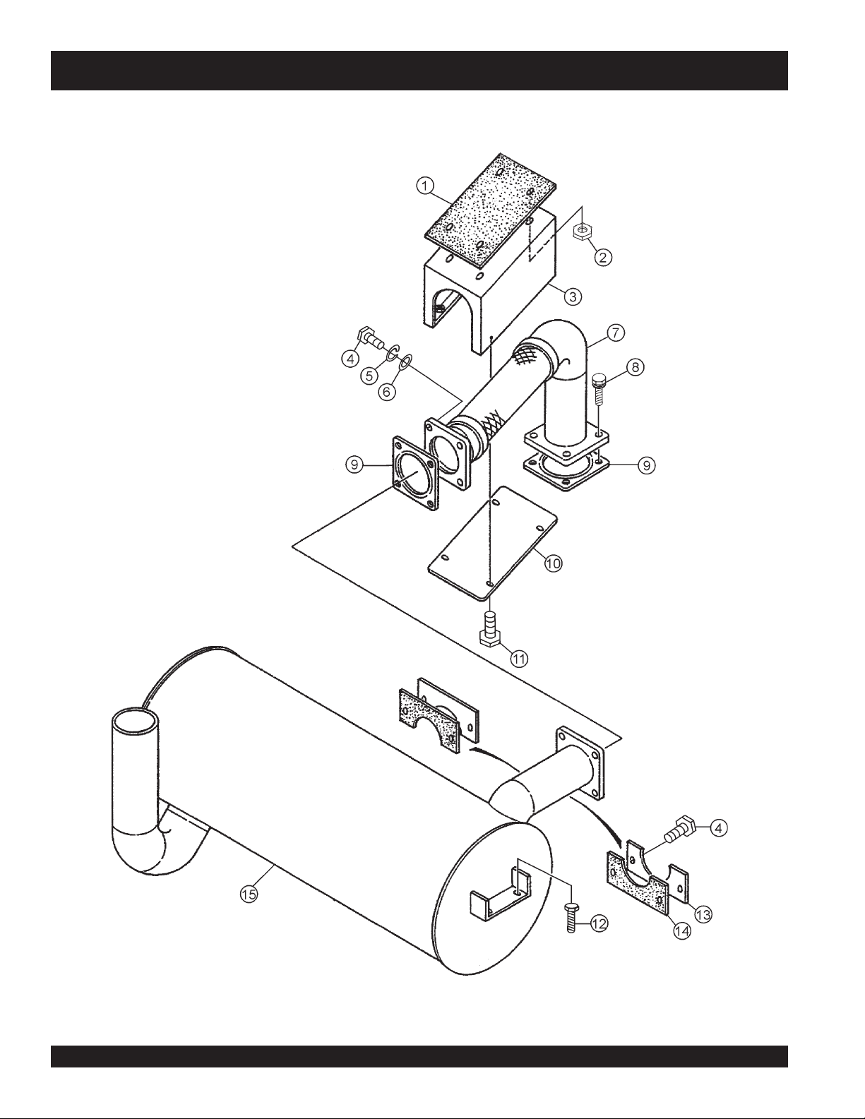
MUFFLER ASSY.
DCA-180SSK — MUFFLER ASSY.
PAGE 80 — DCA-180SSK — PARTS AND OPERATION MANUAL — REV. #3 (06/11/09)
Page 81

DCA-180SSK — MUFFLER ASSY.
MUFFLER ASSY.
NO. PART NO. PART NAME QTY. REMARKS
1 C0334200204 SHEET 1
2 0207308000 HEX. NUT 4
3 C0331400104 COVER, EXHAUST PIPE 1
4 0010112050 HEX. HEAD BOLT 4
5 0030012000 HEX. NUT 8
6 0041212000 PLAIN WASHER 16
7 C0334000003 EXHAUST PIPE 1
8 0012112045 HEX. HEAD BOLT 4
9 6150115751 GASKET ......................................... 2 ........... REPLACES 0602320142
10 C0331400003 COVER, EXHAUST PIPE 1
11 0017108020 HEX. HEAD BOLT 8
12 0017110025 HEX. HEAD BOLT 4
13 8252354004 COVER 2
14 C0334200104 SHEET 2
15 C0331100302 MUFFLER 1
DCA-180SSK — PARTS AND OPERATION MANUAL— REV. #3 (06/11/09) — PAGE 81
Page 82

DCA-180SSK — FUEL TANK ASSY.
PAGE 82 — DCA-180SSK — PARTS AND OPERATION MANUAL — REV. #3 (06/11/09)
Page 83

DCA-180SSK — FUEL TANK ASSY.
MUFFLER ASSY.
NO. PART NO. PART NAME QTY. REMARKS
1 C0364000603 FUEL TANK 1
1-1 0605505030 CAP, FUEL TANK, LOCKING 1
1-1A 0601850590 KEY 1
1-2 0810105400 FUEL FILTER 1
1-3 0264100385 HOSE, FUEL GAUGE 1
1-4 0605515079 HOSE BAND 2
2 8305523104 TANK BAND 2
3 0805003414 PAD, TANK BAND 4
4 0017108020 HEX HEAD BOLT 2
5 0207308000 HEX NUT 2
6 0222100320 TANK SHEET 4
7 0845047504 DRAIN JOINT 1
8 0802011104 PLUG 1
9 0150000018 O-RING 1
10 0191301100 SUCTION HOSE 1
11 0191301200 RETURN HOSE 1
12 0262402050 RETURN HOSE 1
13 0605515014 HOSE BAND 4
14 0605515013 HOSE BAND 2
15 0605503009 FUEL SENSOR 1
16 0802120604 PACKING 1
17 0845039604 RUBBER SEAL 1
DCA-180SSK — PARTS AND OPERATION MANUAL— REV. #3 (06/11/09) — PAGE 83
Page 84

ENCLOSURE ASSY.
DCA-180SSK — ENCLOSURE ASSY.
PAGE 84 — DCA-180SSK — PARTS AND OPERATION MANUAL — REV. #3 (06/11/09)
Page 85

DCA-180SSK — ENCLOSURE ASSY.
ENCLOSURE ASSY.
NO. PART NO. PART NAME QTY. REMARKS
1 C0454001103 SIDE DOOR 1
2 C0454003003 SIDE DOOR 1
3 C0454301004 DUCT 1
4 C0454301804 DUCT 1
5 C0454301404 DUCT 1
6 0845045004 WASHER 12
7 0845047004 HINGE 2
8 C0444200413 DOOR, REAR FRAME 1
9 B9114500104 DOOR POCKET 1
10 0207306000 HEX. NUT 10
11 0845050704 STAY 4
12 8255146104 DOOR ROD 1
13 B9114000102 DOOR HANDLE 1
14 8255146204 DOOR ROD 1
15 M9110100204 HINGE................................................. 2 ............. REPLACES 0845047104
16 8155143703 DOOR, REAR FRAME 1
17 8165157004 WINDOW PLATE 1
18 0207006000 HEX. NUT 12
19 C0424200104 COVER, FRONT FRAME 1
20 C0464100503 ROOF PANEL 1
21 0845052203 FILLER COVER 1
22 1625165204 CHAIN 1
23 0600500090 EMBLEM 2
24 0021106020 MACHINE SCREW 4
25 C0424200003 COVER, FRONT FRAME 1
26 C0414001502 BASE 1
27 0017110020 HEX. HEAD BOLT 4
28 C0424001120 FRONT FRAME 1
ADD THE FOLLOWING DIGITS AFTER THE PART NUMBER
WHEN ORDERING ANY PAINTED PANEL TO INDICATE
COLOR OF UNIT:
1-ORANGE
2-WHITE
3 -SPECTRUM GRAY
4 -SUNBELT GREEN
THE SERIAL NUMBER MAY BE REQUIRED.
DCA-180SSK — PARTS AND OPERATION MANUAL— REV. #3 (06/11/09) — PAGE 85
5 -BLACK
6 -CATERPILLAR YELLOW
7 -CATO GOLD
8 -RED
Page 86

ENCLOSURE ASSY.
DCA-180SSK — ENCLOSURE ASSY.
PAGE 86 — DCA-180SSK — PARTS AND OPERATION MANUAL — REV. #3 (06/11/09)
Page 87

DCA-180SSK — ENCLOSURE ASSY.
ENCLOSURE ASSY.
NO. PART NO. PART NAME QTY. REMARKS
29 0845039703 FILLER BRAKET 1
30 C0414400104 COVER 1
31 0845046904 HINGE 4
32 0017108025 HEX. HEAD BOLT 2
33 0019208020 HEX. HEAD BOLT 20
34 0021008025 MACHINE SCREW 10
35 0601850097 STOPPER 10
36 C0434000302 CENTER FRAME 1
37 M9110100304 HINGE ............................................................ 4 ........ REPLACES 08450-47204
38 C0444000302 REAR FRAME 1
39 C0464200003 ROOF PANEL 1
40 0017108020 HEX. HEAD BOLT 83
41 C0444300704 COVER, REAR FRAME 1
42 C0454300803 DUCT 1
43 0030014000 HEX. NUT 4
44 0040014000 LOCK WASHER 4
45 0041214000 PLAIN WASHER 8
46 0010114050 HEX. HEAD BOLT 4
47 0030020000 HEX. NUT 4
48 0040020000 LOCK WASHER 4
49 0041220000 PLAIN WASHER 8
50 0010120045 HEX. HEAD BOLT 4
51 7765116004 FLOOR PANEL 1
52 0207008000 HEX. NUT 51
53 C0454301704 DUCT 1
54 C0454002903 SIDE DOOR 1
55 0845031504 CAP 12
56 C0454201602 SPLASHER PANEL 1
57 0017108070 HEX. HEAD BOLT 6
58 0021806016 MACHINE SCREW 32
59 0030006000 HEX. NUT 32
60 B9114000002 DOOR HANDLE 4
61 0825007362 DOOR HANDLE 3
62 C0454002003 SIDE DOOR 1
63 C0454300904 DUCT 1
ADD THE FOLLOWING DIGITS AFTER THE PART NUMBER
WHEN ORDERING ANY PAINTED PANEL TO INDICATE
COLOR OF UNIT:
1-ORANGE
2-WHITE
3 -SPECTRUM GRAY
4 -SUNBELT GREEN
THE SERIAL NUMBER MAY BE REQUIRED.
DCA-180SSK — PARTS AND OPERATION MANUAL— REV. #3 (06/11/09) — PAGE 87
5 -BLACK
6 -CATERPILLAR YELLOW
7 -CATO GOLD
8 -RED
Page 88

ENCLOSURE LINING ASSY.
DCA-180SSK — ENCLOSURE LINING ASSY.
PAGE 88 — DCA-180SSK — PARTS AND OPERATION MANUAL — REV. #3 (06/11/09)
Page 89

DCA-180SSK — ENCLOSURE LINING ASSY.
ENCLOSURE LINING ASSY.
NO. PART NO. PART NAME QTY. REMARKS
1 C0494404104 LINING ............................. 1 ........................... FOR ITEM C0454001103
2 C0494404304 LINING ............................. 1 ........................... FOR ITEM C0454003003
3 C0494600804 LINING ............................. 1 ........................... FOR ITEM C0454301004
4 C0494601104 LINING ............................. 1 ........................... FOR ITEM C0454301804
5 C0494600304 LINING ............................. 1 ........................... FOR ITEM C0454301404
19 C0495100003 LINING ............................. 1 ........................... FOR ITEM C0424201004
20 C0494501604 LINING ............................. 1 ........................... FOR ITEM C0464100503
25 C0494500504 LINING ............................. 1 ........................... FOR ITEM C0464200003
38 C0494300504 LINING ............................. 2 ........................... FOR ITEM C0444000302
42 C0494600403 LINING ............................. 1 ........................... FOR ITEM C0454300803
53 C0494601004 LINING ............................. 1 ........................... FOR ITEM C0454301704
54 C0494404204 LINING ............................. 1 ........................... FOR ITEM C0454002903
63 C0494600704 LINING ............................. 1 ........................... FOR ITEM C0454300904
DCA-180SSK — PARTS AND OPERATION MANUAL— REV. #3 (06/11/09) — PAGE 89
Page 90

RUBBER SEALS ASSY.
DCA-180SSK — ENCLOSURE ASSY. (RUBBER SEALS)
PAGE 90 — DCA-180SSK — PARTS AND OPERATION MANUAL — REV. #3 (06/11/09)
Page 91

DCA-180SSK — ENCLOSURE ASSY. (RUBBER SEALS)
RUBBER SEALS ASSY.
NO. PART NO. PART NAME QTY. REMARKS
1 0228901080 RUBBER SEAL 6
2 0228900840 RUBBER SEAL 4
3 0228900520 RUBBER SEAL 2
4 0228901070 RUBBER SEAL 4
5 0229201200 RUBBER SEAL 4
6 0228800600 RUBBER SEAL 2
7 0228801040 RUBBER SEAL 2
8 0229201100 RUBBER SEAL 1
9 0228100320 RUBBER SEAL 1
10 0228100540 RUBBER SEAL 2 2
DCA-180SSK — PARTS AND OPERATION MANUAL— REV. #3 (06/11/09) — PAGE 91
Page 92

NAME PLATE AND DECALS
DCA-180SSK — NAME PLATE AND DECALS
PAGE 92 — DCA-180SSK — PARTS AND OPERATION MANUAL — REV. #3 (06/11/09)
Page 93

DCA-180SSK — NAME PLATE AND DECALS
NAMEPLATE ASSY.
NO PART NO PART NAME QTY. REMARKS
1-1 C1552000403 DECAL; HANDLING PROCEDURES .......... 1 ......... C15200040
1-2 B1552000103 DECAL; CAUTION ...................................... 2 ......... B15200010
CONTROL BOX GROUP
2-1 0800520100 DECAL; ON-OFF ......................................... 1 ......... AT-202
2-2 0800520904 PLATE; AMMETER CHANGE-OVER
SWITCH ...................................................... 1 ......... N-2438
2-3 0800520814 PLATE; VOLTMETER CHANGE-OVER
SWITCH ...................................................... 1 ......... N-24391
2-4 0840624504 DECAL; CIRCUIT BREAKER ...................... 1 ......... S-3031
2-5 0840624604 DECAL; PANEL LIGHT SWITCH ................ 1 ......... S-3032
2-6 0840624704 DECAL; PILOT LAMP ................................. 1 ......... S-3033
2-7 0840624804 DECAL; VOLTAGE REGULATOR ................ 1 ......... S-3034
2-8 B9531100604 DECAL; WARNING ELECTRIC SHOCK
HAZARD ..................................................... 2 ......... B93110060
2-9 C0551000903 DECAL; SETTING FOR OUTPUT
VOLTAGE .................................................... 1 ......... C05100090
2-10 C2551000004 DECAL; SAFETY INSTRUCTIONS............. 1 ......... C25100000
2-11 C0561103403 DECAL; WHISPERWATT 180 ...................... 1 ......... C06110340
ENGINE & RADIATOR GROUP
3-1 1320610603 DECAL; WATER-OIL ................................... 1 ......... S-1760
3-2 6360610304 DECAL; WATER .......................................... 1 ......... S-1880
3-3 6360620204 DECAL; OIL DRAIN PLUG .......................... 1 ......... S-1885
3-4 B9504000304 DECAL; CAUTION HOT PARTS .................. 1 ......... B90400030
3-5 B9504000404 DECAL; WARNING MOVING PARTS .......... 2 ......... B90400040
3-6 B9504100104 DECAL; WARNING HOT COOLANT ........... 1 ......... B90410010
ENGINE OPERATING PANEL GROUP
4-1 C0551000504 DECAL; BATTERY SWITCH ....................... 1 ......... C05100050
4-2 C1552000013 DECAL; OPERATING PANEL ..................... 1 ......... C15200001
4-3 C1552000104 DECAL; FUEL LEAK DETECTED .............. 1 ......... C15200010
DCA-180SSK — PARTS AND OPERATION MANUAL— REV. #3 (06/11/09) — PAGE 93
Page 94

NAME PLATE AND DECALS
DCA-180SSK — NAME PLATE AND DECALS
PAGE 94 — DCA-180SSK — PARTS AND OPERATION MANUAL — REV. #3 (06/11/09)
Page 95

DCA-180SSK — NAME PLATE AND DECALS
NAME PLATE AND DECALS
NO PART NO PART NAME QTY. REMARKS
OUTPUT TERMINAL GROUP
5-1 0840614104 DECAL; GROUND ............................................1 ........... S-2635
5-2 0840619904 DECAL; DANGER HIGH VOLTAGE ................. 1 ........... S-2731
5-3 9039209064 DECAL; START CONTACT .............................. 1 ........... S-4468
5-4 B9511100304 DECAL; WARNING ...........................................1 ........... B91110030
5-5 B9511100404 DECAL; WARNING ELECTRIC SHOCK
HAZARD............................................................ 1 ........... B91110040
5-6 B9531100504 DECAL; WARNING ELECTRIC SHOCK .......... 1 ........... B93110050
HAZARD
5-7 C0551000404 DECAL; 3-PHASE OUTPUT TERMINAL .......... 1 ........... C05100040
5-8 C0551001503 DECAL; RECEPTACLE & CIRCUIT
BREAKER ......................................................... 1 ........... C05100150
5-9 C1552000204 DECAL; WATER HEATER ................................. 1 ........... C15200020
5-10 C1552000304 DECAL; BATTERY CHARGER .........................1 ........... C15200030
BATTERY GROUP
6-1 0800689404 DECAL; + ........................................................... 1 ............ S-2090
6-2 0800689504 DECAL; - ............................................................ 1 ............ S-2091
6-3 C9505300004 DECAL; CAUTION............................................. 1 ............ C90530000
MUFFLER GROUP
7-1 B9504200004 DECAL; WARNING ENGINE EXHAUST ..........1 ............ B90420000
FUEL PIPING GROUP
8-1 0800688404 DECAL; FUEL INLET ........................................1 ............ S-1344
8-2 0800688504 DECAL; FUEL OUTLET .................................... 1 ............ S-1345
8-3 1320620904 DECAL; DIESEL FUEL ...................................... 1 ............ S-1756
8-4 B9504500004 DECAL; WARNING DIESEL FUEL ................... 1 ............ B90450000
ENCLOSURE GROUP
9-1 1320621504 DECAL; SUPPORT HOOK ...............................2 ............ S-2257
9-2 0600500090 EMBLEM 2
0021106016 MACHINE SCREW 4
DCA-180SSK — PARTS AND OPERATION MANUAL— REV. #3 (06/11/09) — PAGE 95
Page 96

Effective: July 1, 2000
TERMS AND CONDITIONS OF SALE — PARTS
PAYMENT TERMS
Terms of payment for parts are net 10 days.
FREIGHT POLICY
All parts orders will be shipped collect or
prepaid with the charges added to the invoice.
All shipments are F.O.B. point of origin.
Multiquip’s responsibility ceases when a signed
manifest has been obtained from the carrier,
and any claim for shortage or damage must be
settled between the consignee and the carrier.
MINIMUM ORDER
The minimum charge for orders from Multiquip
is $15.00 net. Customers will be asked for
instructions regarding handling of orders not
meeting this requirement.
RETURNED GOODS POLICY
Return shipments will be accepted and credit
will be allowed, subject to the following
provisions:
1. A Returned Material Authorization must
be approved by Multiquip prior to shipment.
2. To obtain a Return Mater ial Authorization,
a list must be provided to Multiquip Parts
Sales that defines item numbers,
quantities, and descriptions of the items to
be returned.
a. The parts numbers and descriptions
must match the current parts price
list.
b. The list must be typed or computer
generated.
c. The list must state the reason(s) for
the return.
d. The list must reference the sales
order(s) or invoice(s) under which
the items were originally purchased.
e. The list must include the name and
phone number of the person
requesting the RMA.
3. A copy of the Return Material
Authorization must accompany the return
shipment.
4. Freight is at the sender’s expense. All
5. Parts must be in new and resalable
6. The following items are not returnable:
7. The sender will be notified of any material
8. Such material will be held for 5 working
9. Credit on returned parts will be issued at
10. In cases where an item is accepted for
11. Credit issued will be applied to future
PRICING AND REBATES
parts must be returned freight prepaid to
Multiquip’s designated receiving point.
condition, in the original Multiquip package
(if any), and with Muiltiquip part numbers
clearly marked.
a. Obsolete parts. (If an item is listed
in the parts price book as being
replaced by another item, it is
obsolete.)
b. Any parts with a limited shelf life
(such as gaskets, seals, “O” rings,
and other rubber parts) that were
purchased more than six months
prior to the return date.
c. Any line item with an extended dealer
net price of less than $5.00.
d. Special order items.
e. Electrical components.
f. Paint, chemicals, and lubricants.
g. Decals and paper products.
h. Items purchased in kits.
received that is not acceptable.
days from notification, pending
instructions. If a reply is not received
within 5 days, the material will be returned
to the sender at his expense.
dealer net price at time of the original
purchase, less a 15% restocking charge.
which the original purchase document
can not be determined, the price will be
based on the list price that was effective
twelve months prior to the RMA date.
purchases only.
Prices are subject to change without prior
notice. Price changes are effective on a specific
date and all orders received on or after that date
will be billed at the revised price. Rebates for
price declines and added charges for price
increases will not be made for stock on hand at
the time of any price change.
Multiquip reserves the right to quote and sell
direct to Government agencies, and to Original
Equipment Manufacturer accounts who use
our products as integral parts of their own
products.
SPECIAL EXPEDITING SERVICE
A $20.00 to $50.00 surcharge will be added to
the invoice for special handling including bus
shipments, insured parcel post or in cases
where Multiquip must personally deliver the
parts to the carrier.
LIMITATIONS OF SELLER’S LIABILITY
Multiquip shall not be liable here under for
damages in excess of the purchase price of the
item with respect to which damages are claimed,
and in no event shall Multiquip be liable for loss
of profit or good will or for any other special,
consequential or incidental damages.
LIMITATION OF WARRANTIES
No warranties, express or implied, are made in
connection with the sale of parts or trade
accessories nor as to any engine not
manufactured by Multiquip. Such warranties
made in connection with the sale of new,
complete units are made exclusively by a
statement of warranty packaged with such
units, and Multiquip neither assumes not
authorizes any person to assume for it any
other obligation or liability whatever in
connection with the sale of its products. A part
from such written statement of warranty, there
are no warranties, express, implied or statutory,
which extend beyond the description of the
products on the face hereof.
PAGE 96 — DCA-180SSK — PARTS AND OPERATION MANUAL — REV. #3 (06/11/09)
Page 97

NOTE PAGE
DCA-180SSK — PARTS AND OPERATION MANUAL— REV. #3 (06/11/09) — PAGE 97
Page 98

PARTS AND OPERATION MANUAL
©
HERE’S HOW TO GET HELP
PLEASE HAVE THE MODEL AND SERIAL
NUMBER ON-HAND WHEN CALLING
MULTIQUIP CORPORATE OFFICE
18910 Wilmington Ave Tel. (800) 421-1244
Carson, CA 90746 Fax (800) 537- 3927
Contact: mq@multiquip.com
Web: www.multiquip.com
MQ Power
1800 Water Ridge Rd. Tel. (800) 883-2551
Suite 500/600 Fax (972) 315-1847
Lewisville, TX 75057
Contact: mqpower@multiquip.com
Web: www.mqpower.com
MQ Parts Department
800-427-1244 Fax: 800-672-7877
310-537-3700 Fax: 310-637-3284
Service/Tech Support/Warranty
800-835-2551 Fax: 310-638-8046
COPYRIGHT 2009, MULTIQUIP INC.
MQ Power and the MQ Power logo are registered trademarks of Multiquip Inc. and may not be used, reproduced, or altered without written permission. All other trademarks are the
property of their respective owners and used with permission.
This manual MUST accompany the equipment at all times. This manual is considered a permanent part of the equipment and should remain with the unit if resold.
The information and specifications included in this publication were in effect at the time of approval for printing. Illustrations, descriptions, references and technical data contained in
this manual are for guidance only and may not be considered as binding. Multiquip Inc. reserves the right to discontinue or change specifications, design or the information published
in this publication at any time without notice and without incurring any obligations.
Further, MQ Power disclaims any warranties or guaranties, expressed or implied, with regards to the information contained in this manual.
Your Local Dealer is:
Manufactured for
Multiquip Inc.
by
DENYO CO., LTD, JAPAN
 Loading...