

Page 1

PARTS AND OPERATION MANUAL
OPERATION MANUAL
WHISPERWATT
TM
SERIES
MODEL DCA-15SPXU4
60 Hz GENERATOR
Revision #0 (03/31/11)
THIS MANUAL MUST ACCOMPANY
THE EQUIPMENT AT ALL TIMES.
Page 2
PROPOSITION 65 WARNING
Diesel engine exhaust and some of
PAGE 2 — DCA-15SPXU4— OPERATION MANUAL — REV. #0 (03/31/11)
Page 3

NOTE PAGE
1
DCA-15SPXU4— OPERATION MANUAL — REV. #0 (03/31/11) — PAGE 3
Page 4

MQ POWER DCA-15SPXU4MQ POWER DCA-15SPXU4
MQ POWER DCA-15SPXU4
MQ POWER DCA-15SPXU4MQ POWER DCA-15SPXU4
TMTM
TM
WHISPERWHISPER
WHISPER
WHISPERWHISPER
California Proposition 65 Warning ..................................... 2
Table Of Contents ............................................................. 4
Parts Ordering Procedures ............................................... 5
Specifications ................................................................... 6
Dimensions (Top, Side, Front) .......................................... 7
Safety Message Alert Symbols .................................... 8-9
Rules for Safe Operation ........................................... 10-14
Installation ................................................................. 16-17
General Information ........................................................ 18
Major Components ......................................................... 19
Generator Control Panel ............................................ 20-21
Output Terminal Panel Familiarization ........................ 22-24
Load Application/Max Amperage .................................... 25
Gauge Reading/Terminal Panel Connections .................. 26
Setup ......................................................................... 27-30
Generator Start-up Procedure ................................... 31-32
Generator Shut-Down Procedure .................................... 33
Maintenance (Engine) ................................................ 34-36
Maintenance (Trailer) ................................................. 37-39
Generator Wiring Diagram ............................................... 40
Engine Wiring Diagram ................................................... 41
Troubleshooting (Engine) ........................................... 42-43
Troubleshooting (Generator) ............................................ 44
Troubleshooting (Pre-Heat Lamp Codes) ........................ 45
WW
W
WW
AA
A
AA
TTTT
TT
TTTT
TMTM
GENERATORGENERATOR
GENERATOR
GENERATORGENERATOR
NOTE
TABLE OF CONTENTS
Specification and part
number are subject to
change without notice.
PAGE 4 — DCA-15SPXU4— OPERATION MANUAL — REV. #0 (03/31/11)
Page 5

NOTE PAGE
1
DCA-15SPXU4— OPERATION MANUAL — REV. #0 (03/31/11) — PAGE 5
Page 6
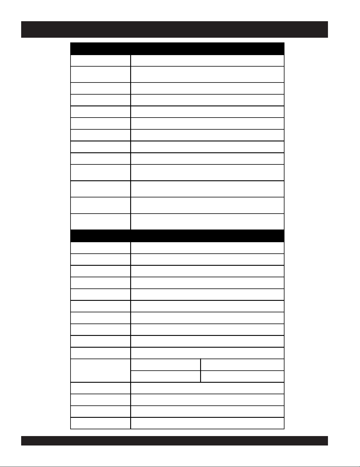
DCA-15SPXU4 — SPECIFICATIONS
Table 1. Generator Specifications
Model DCA-15SPXU4
Type
Phase
Standby Output
Prime Output
Vo lt ag e
Frequency
Speed
Power Factor
Aux. AC Power
(GFCI)
Aux. AC Power
(L5-30R)
Aux. AC Power
(L6-30R )
Aux. AC Power
(CS6369)
Revolving field, self ventilated, open protected type synchronous
generator
Single Phase 3-Wire
16.5 KW
15 KW
240V/120
60 Hz
1800 rpm
1.0
2.4 KW @120 VAC Single Phase, 60 Hz
3.6 KW@120 VAC Single Phase, 60 Hz
7.2 KW@240 VAC Single Phase, 60 Hz
12 KW@240 VAC Single Phase, 60 Hz
6 KW@120 VAC Single Phase, 60 Hz
Table 2. Engine Specifications
Model
Type
No. of Cylinders
Bore x Stroke
Rated Output
Displacement
Starting
Coolant Capacity
Lube Oil Capacity
Fuel Tank Capacity
Fuel Consumption
Battery
Fuel
Dry Weight
KUBOTA V2203-M
4 Cycle, water-cooled, swirl combustion chamber type
4 cylinders
3.43 in. x 3.64 in. (87 mm x 92.4 mm)
27.1 HP/1800 rpm
134.1 cu. in. (2,197 cc)
Electric
2.09 gal. (7.9 liters)
2.00 gal. (7.6 liters)
16.4 gal. (62 liters)
1.37 gal. (5.2 L)/hr at full load 1.08 gal. (4.08 L)/hr at 3/4 load
0.83 gal. (3.14 L)/hr at 1/2 load 0.62 gal. (2.34 L)/hr at 1/4 load
12V- 65AH (27:525A)
#2 Diesel Fuel
577 kg
Total Weight
649 kg
PAGE 6 — DCA-15SPXU4— OPERATION MANUAL — REV. #0 (03/31/11)
Page 7
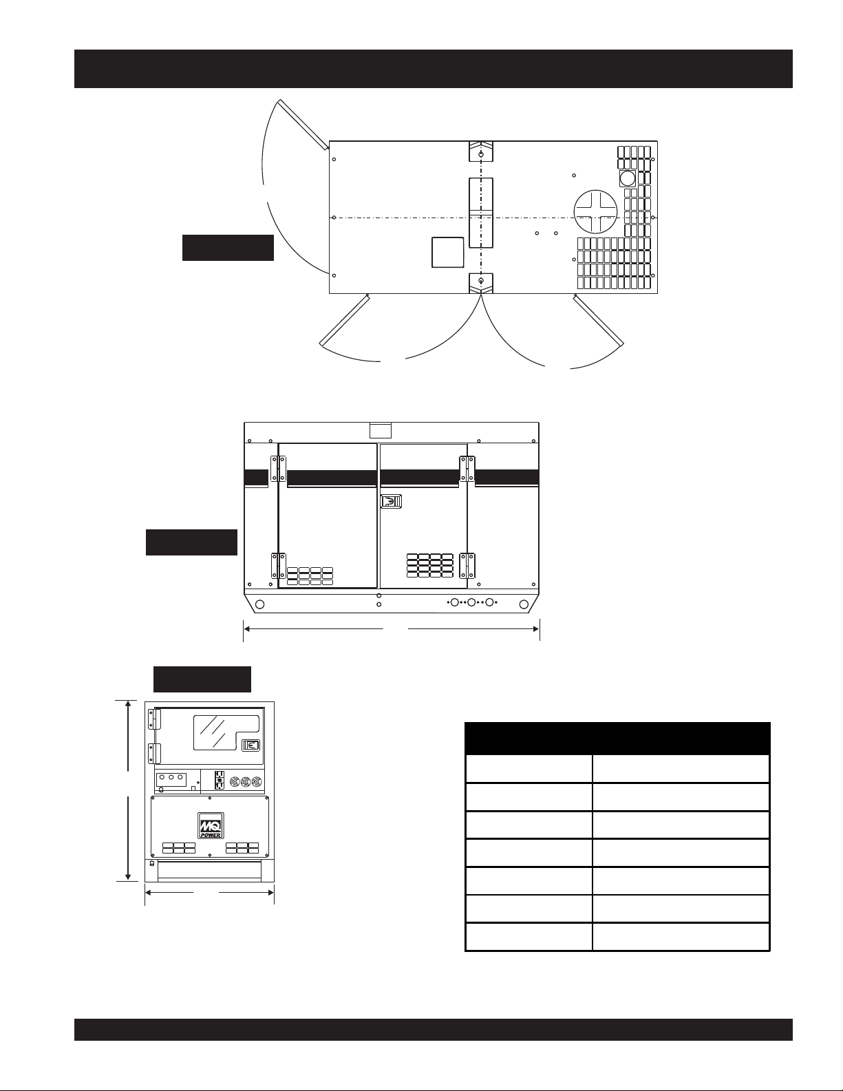
TOP VIEW
DCA-15SPXU4 — DIMENSIONS (TOP, SIDE AND FRONT)
A
Figure 1. Dimensions
SIDE VIEW
FRONT VIEW
15
WHISPERWATT
B
MQPOWER
D
C
TABLE 3. DIMENSIONS
UNV
E
Reference Letter Dimension in. (mm.)
A 21.65 (550)
Denyo
B 20.07 (510)
C 21.85 (555)
D 61.02 (1,550)
F
E 35.43 (900)
F 25.60 (650)
1
DCA-15SPXU4— OPERATION MANUAL — REV. #0 (03/31/11) — PAGE 7
Page 8
DCA-15SPXU4 — SAFETY MESSAGE ALERT SYMBOLS
FOR YOUR SAFETY AND THE SAFETY OF OTHERS!
Safety precautions should be followed at all times when
operating this equipment. Failure to read and understand the
Safety Messages and Operating Instructions could result in
injury to yourself and others.
This Owner's Manual has been
NOTE
developed to provide complete
instructions for the safe and
efficient operation of the
MQ Power
Model DCA-15SPXU4
HAZARD SYMBOLS
Potential hazards associated with the operation of this
equipment will be referenced with "
appear throughout this manual, and will be referenced in
conjunction with Safety "
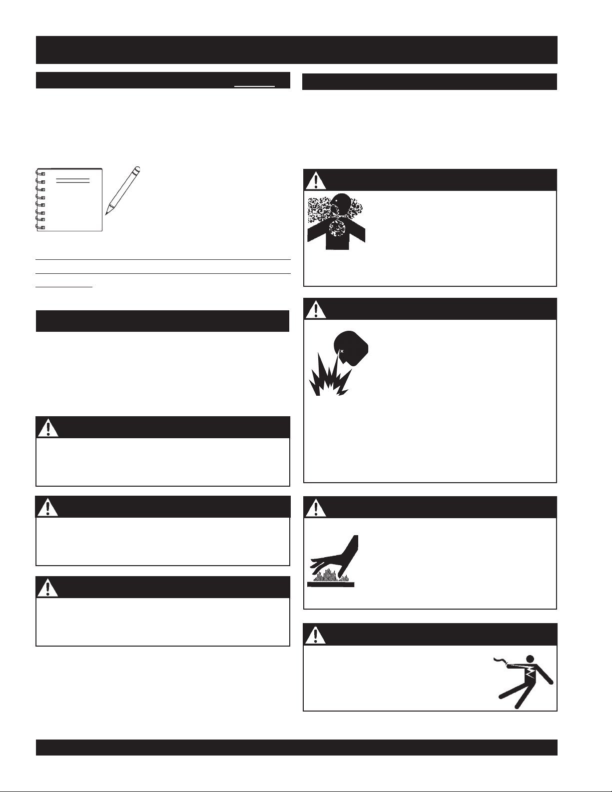
WARNING - LETHAL EXHAUST GASES
Whisperwatt™ Generator.
Before using this generator, ensure that the operating
individual has read and understands all instructions in
this manual.
SAFETY MESSAGE ALERT SYMBOLS
The three (3) Safety Messages shown below will inform you
about potential hazards that could injure you or others. The
Safety Messages specifically address the level of exposure
to the operator, and are preceded by one of three words:
DANGER, WARNING, or CAUTION.
DANGER
You WILL be KILLED or SERIOUSLY injured if you
do not follow directions.
equipment in a confined area or enclosed structure that
does not provide ample free flow air.
WARNING - EXPLOSIVE FUEL
DO NOT overfill tank, since spilled fuel could ignite if it
comes into contact with hot engine parts or sparks from
the ignition system. Store fuel in approved containers, in
well-ventilated areas and away from sparks and flames.
NEVER use fuel as a cleaning agent.
Hazard Symbols
Message Alert Symbols
Gasoline engine exhaust gases contain
poisonous carbon monoxide. This gas is
colorless and odorless, and can cause
DEATH
if inhaled. NEVER operate this
Diesel fuel
its vapors can cause an explosion if
ignited. DO NOT start the engine near
spilled fuel or combustible fluids.
DO NOT fill the fuel tank while the engine
is running or hot.
is extremely flammable, and
" which
".
WARNING
You COULD be KILLED or SERIOUSLY injured if
you do not follow directions.
CAUTION
You CAN be injured if you do not follow directions
PAGE 8 — DCA-15SPXU4— OPERATION MANUAL — REV. #0 (03/31/11)
WARNING - BURN HAZARDS
Engine components can generate extreme
heat. To prevent burns, DO NOT touch these
areas while the engine is running or
immediately after operations. NEVER
operate the engine with heat shields or heat
guards removed.
DANGER - ELECTROCUTION HAZARDS
During operation of this generator, there
exists the possibility of
electrical shock or burn,
severe bodily harm
electrocution,
which can cause
or even
DEATH!
Page 9
DCA-15SPXU4 — SAFETY MESSAGE ALERT SYMBOLS
WARNING - ROTATING PARTS
NEVER operate equipment with covers,
or guards removed. Keep
hair
and clothing away from all moving
parts to prevent injury.
CAUTION - ACCIDENTAL STARTING
ALWAYS place the engine ON/OFF
switch (MPEC) in the OFF/RESET
position when the generator is not in use.
CAUTION - OVER-SPEED CONDITIONS
NEVER tamper with the factory settings
of the engine governor or settings.
Personal injury and damage to the engine
or equipment can result if operating in
speed ranges above maximum allowable.
fingers, hands
CAUTION - RESPIRATORY HAZARDS
,
CAUTION - SIGHT AND HEARING HAZARDS
CAUTION - EQUIPMENT DAMAGE MESSAGES
Other important messages are provided throughout this
manual to help prevent damage to your generator, other
property, or the surrounding environment.
ALWAYS wear approved
protection.
ALWAYS wear approved
hearing
protection.
respiratory
eye
and
NOTE
Wet-Stacking is a common problem with diesel engines
which are operated for extended periods with light or no
load applied. When a diesel engine operates without
This generator, other property, or
the surrounding environment
could be damaged if you do not
follow instructions.
sufficient load (less than 40% of the rated output) it will
not operate at its optimum temperature. This will allow
unburned fuel to accumulate in the exhaust system, which
can foul the fuel injectors, engine valves and exhaust
system, including turbocharges, and reduce the operating
performance.
In order for a diesel engine to operate at peak efficiency it
must be able to provide fuel and air in the proper ratio and
at a high enough engine temperature for the engine to
completely burn all of the fuel.
Wet stacking does usually cause any permanent damage
and can be alleviated if additional load is applied to relieve
the condition. It can reduce the system performance and
increase maintenance. Applying an increasing load over a
period of time until the excess fuel is burned off and the
system capacity is reached usually can repair the condition.
This can take several hours to burn off the accumulated
unburned fuel.
CAUTION - ENGINE LOAD (WET-STACKING)
1
DCA-15SPXU4— OPERATION MANUAL — REV. #0 (03/31/11) — PAGE 9
Page 10
DCA-15SPXU4 — RULES FOR SAFE OPERATION
DANGEROUS
GAS FUMES
Denyo
■
DANGER - READ THIS MANUAL!
Failure to follow instructions in this manual may lead to
serious injury
or even
DEATH
! This equipment is to be
operated by trained and qualified personnel only! This
equipment is for industrial use only.
The following safety guidelines should always be used when
operating the
DCA-15SPXU4 Whisperwatt™ AC Generator.
General Safety:
■
DO NOT operate or service this
equipment before reading this entire
manual.
The operator MUST BE familiar with proper safety
precautions and operations techniques before using
generator.
■
This equipment should not be operated by persons under
18 years of age.
■
NEVER operate this equipment without proper protective
clothing, shatterproof glasses, steel-toed boots and other
protective devices required by the job.
NEVER use accessories or attachments, which are not
recommended by Multiquip for this equipment. Damage
to the equipment and/or injury to user may result.
■
NEVER touch the hot exhaust
manifold, muffler or cylinder.
Allow these parts to cool before
servicing engine or generators.
■
The engine section of this generators requires an adequate
free flow of cooling air.
any enclosed or narrow area where free flow of the air is
restricted. If the air flow is restricted it will cause serious
damage to the generators
or engine and may cause
injury to people.
Remember the generator's
engine gives off
carbon monoxide gas.
NEVER
DEADLY
operate the generator in
■
■
NEVER operate this equipment when not
feeling well due to fatigue, illness or taking
■
medicine.
■
NEVER operate this equipment under the influence or
drugs or alcohol.
■
■
ALWAYS wear proper respiratory (mask),
hearing and eye protection equipment when
operating the generator.
■
Whenever necessary, replace nameplate, operation and
■
safety decals when they become difficult read.
■
Manufacturer does not assume responsibility for any
accident due to equipment modifications. Unauthorized
equipment modification will void all warranties.
ALWAYS refuel in a well-ventilated area, away from sparks
and open flames.
ALWAYS use extreme caution when
working with flammable liquids. When
refueling, stop the engine and allow it to
cool. DO NOT
smoke
around or near the
machine. Fire or explosion could result
from fuel vapors, or if fuel is spilled on a
hot engine.
NEVER operate the generator in an
explosive atmosphere or near
combustible materials. An explosion or
fire could result causing severe
bodily
harm or even death.
NEVER disconnect any
These devices are intended for operator safety. Disconnection
of these devices can cause severe injury, bodily harm or even
death! Disconnection of any of these devices will void all
warranties.
"emergency or safety devices"
.
PAGE 10 — DCA-15SPXU4— OPERATION MANUAL — REV. #0 (03/31/11)
Page 11

DCA-15SPXU4 — RULES FOR SAFE OPERATION
■
ALWAYS be sure the operator is familiar with proper safety
precautions and operation techniques before using
generators.
■
NEVER leave the generator unattended, turn off engine when
unattended.
■
Unauthorized equipment modifications will void all warranties.
■
ALWAYS ensure generator is on level ground before use.
■
DO NOT place hands or fingers inside generators engine
compartment when engine is running.
■
NEVER run engine without air cleaner. Severe engine damage
may occur.
■
NEVER change or adjust the engine speed which has been
set at the factory prior to shipping.
Power Cord Safety
■
NEVER let power cables or cords
■
NEVER
is being transfer to a load.
■
NEVER use a defective or frayed power cable. Check the
cable for cuts in the insulation.
■
NEVER use a extension cord that is frayed or damaged where
the insulation has been cut.
■
ALWAYS make certain that proper power or extension cord
has been selected for the job See Table 6.
stand in water
while AC power from the generators
lay in wate
r.
Grounding Safety
■
ALWAYS make sure that electrical circuits are properly
grounded
local codes before operating generator. Severe
death!
ungrounded generator.
■
ALWAYS make sure the generators are properly grounded to
a suitable earth ground (GROUND ROD). See installation in
this manual.
per the
by electrocution can result from operating an
National Electrical Code
(NEC) and
injury
Maintenance Safety
■
■
■
■
■
■
■
■
■
■
■
■
■
or
■
NEVER lubricate components or attempt service on a running
machine.
High Temperatures – Always stop engine and
allow the engine to cool before adding fuel, oil
or performing service and maintenance
hot!
functions. Contact with
cause serious burns.
Keep the machinery in proper running condition.
Fix damage to the machine immediately and replace any
broken parts immediately.
ALWAYS replace any worn or damaged warning decals.
ALWAYS store equipment properly when it is not being used.
Equipment should be stored in a clean, dry location out of the
reach of children and un-authorized personnel.
The electrical voltage required to operate the generator can
cause severe injury or even death through physical contact
with live circuits.
performing maintenance on the generator.
Dispose of hazardous waste properly. Examples of potentially
hazardous waste are used motor oil, fuel and fuel filters.
DO NOT use food or plastic containers to dispose of
hazardous waste.
DO NOT pour waste, oil or fuel directly onto the ground,
down a drain or into any water source.
Turn all circuit breakers OFF before
components can
ALWAYS allow the machine a proper amount of time to
cool before servicing.
ALWAYS service air cleaner frequently to prevent engine
malfunction.
ALWAYS disconnect the
NEGATIVE battery terminal
before performing service on the generator.
Follow all battery safety guidelines listed in this manual
when handleing or servicing the generator.
■
NEVER use
gas piping
as an electrical ground.
DCA-15SPXU4— OPERATION MANUAL — REV. #0 (03/31/11) — PAGE 11
1
Page 12
DCA-15SPXU4 — RULES FOR SAFE OPERATION
WARNING - BURN HAZARDS
To prevent burns, DO NOT touch or open any of the below
mentioned components while the engine is
running or immediately after operations.
Always allow sufficient time for the engine
and generator to cool before performing
maintenance.
■
Radiator Cap - Removing the radiator cap while the
engine is hot will result in high pressurized, boiling water
to gush out of the radiator, causing severe scalding to
any persons in the general area of the generator.
■
Coolant Drain Plug - Removing the
coolant drain plug while the engine is
hot will result in hot coolant gushing
out of the coolant drain plug, therefore
causing severe scalding to any persons
in the general area of the generator.
■
Engine Oil Drain Plug - Removing the engine oil drain
plug while the engine is hot will result in hot oil gushing
out of the oil drain plug, therefore causing severe
scalding to any persons in the general area of the
generator.
Battery Safety
Use the following guidelines when handling the battery:
■
The battery contains acids that can
cause injury to the eyes and skin. To
avoid eye irritation,
glasses.
■
Use well insulated gloves when picking up the battery.
DANGER - EXPLOSION HAZARDS
The risk of an explosion exists when performing service
on the battery. To avoid
■■
■
DO NOT drop the battery. There
■■
is the possibility of risk that the
battery may explode.
■■
■
DO NOT expose the battery to
■■
open flames, sparks, cigarettes
etc. The battery contains combustible gases and liquids.
If these gases and liquids come in contact with a flame
or spark, an explosion could occur.
■■
■
ALWAYS keep the battery charged. If the battery is not
■■
charged a buildup of combustible gas will occur.
always
wear safety
severe injury
or
DEATH:
■■
■
ALWAYS keep battery charging and cables in good
■■
working condition. Repair or replace all worn cables.
■■
■
ALWAYS recharge the battery in an vented air
■■
environment, to avoid risk of a dangerous concentration
of combustible gases.
■■
■
In case the battery liquid (dilute sulfuric acid) comes in
■■
contact with
immediately with plenty of water.
■■
■
In case the battery liquid (dilute sulfuric acid) comes in
■■
contact with your
plenty of water and contact the nearest doctor or hospital
to seek medical attention.
clothing or skin
EYES
, rinse skin or clothing
, rinse eyes immediately with
PAGE 12 — DCA-15SPXU4— OPERATION MANUAL — REV. #0 (03/31/11)
Page 13
DCA-15SPXU4 — RULES FOR SAFE OPERATION
ACCIRCUIT
BREAKER
O
F
F
22A
120
V
20A
120V
OFF
ON
GA-2.9R
ACCIRCUIT
BREAKER
O
F
F
22
A
120
V
20A
120V
OFF
ON
GA-2.9R
ACCIRCUIT
BREAKER
OFF
22
A
120
V
20A
120V
OFF
ON
GA-2.9R
DANGERDANGER
DANGER
DANGERDANGER
During operation of this generation, there
exists the possibility of
electrical shock or burn
cause
severe bodily harm
DEATH!
To avoid these hazards:
NEVER use
Electrocution HazardsElectrocution Hazards
Electrocution Hazards
-
Electrocution HazardsElectrocution Hazards
electrocution
, which can
or even
damaged
or
worn
cables when connecting
Engine exhaust gases contain
,
poisonous carbon monoxide. This gas
is colorless and odorless, and can
cause death if inhaled. NEVER operate
this equipment in a confined area or
enclosed structure that does not provide
ample free flow air.
equipment to the generator. Make sure power connecting
cables are securely connected to the generator’s output
receptacles, incorrect connections may cause damage
to the generators and electrical shock.
NEVER grab or touch a live
power cord with wet hands, the
possibility exist of electrical
shock, electrocution, and even
death!
DANGERDANGER
DANGER
DANGERDANGER
Lethal Exhaust Gas HazardsLethal Exhaust Gas Hazards
-
Lethal Exhaust Gas Hazards
Lethal Exhaust Gas HazardsLethal Exhaust Gas Hazards
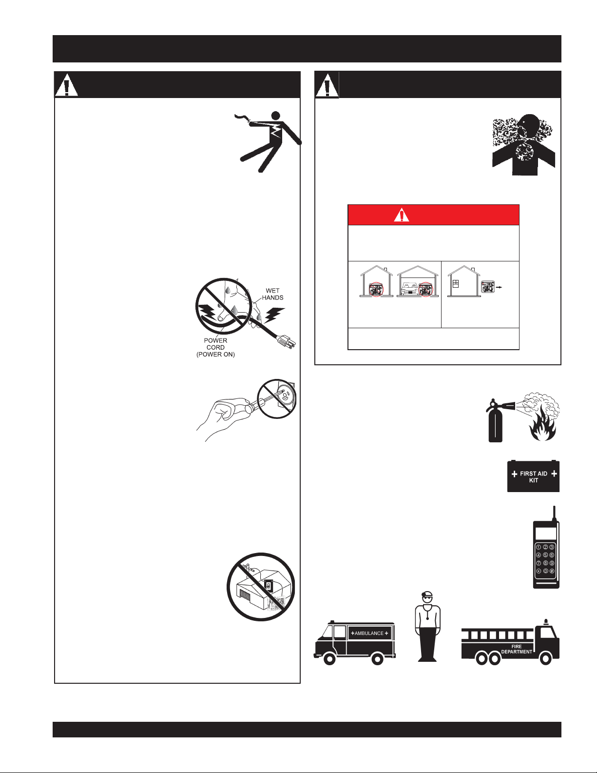
DANGER
Using a generator indoors .CAN KILL YOU IN MINUTES
Generator exhaust contains carbon monoxide. This is
a posion you cannot see or smell
2900
F
A
F
2
O
2
ACCIRCUIT
2900
F
A
F
2
O
2
ACCIRCUIT
BREAKER
NEVER use inside a home
or garage, even if doors
and windows are open
Avoid other generator hazards.
2900
F
A
F
2
O
2
ACCIRCUIT
BREAKER
Only use OUTSIDE and
far away from windows,
doors, and vents.
BREAKER
OFF
.READ MANUAL BEFORE USE
Emergencies
NEVER insert any objects into
the output receptacles during
■
ALWAYS know the location of the
nearest
operation. This is extremely
dangerous. ALWAYS turn-off
the generators and place all circuit breakers in the “OFF”
position when contact with the output receptacles is
required. There exist the possibility of
electrocution,
■
ALWAYS know the location of the nearest
first aid kit
electrical shock or burn, which can cause severe
bodily harm or even death
Backfeed to a utility system can cause
electrocution
NEVER connect the generators to a
building's electrical system without a
transfer switch or other approved device.
All installations should be performed by
licensed electrician
a
with all applicable laws and electrical
codes. Failure to do so could result in
electrical shock or burn causing serious
injury or even death!
and or property damage.
!
in accordance
■
In emergencies
nearest phone or
Also know the phone numbers of the nearest
ambulance, doctor
information will be invaluable in the case of an
emergency.
fire extinguisher
.
.
always
know the location of the
keep a phone on the job site
and
fire department
.
. This
1
DCA-15SPXU4— OPERATION MANUAL — REV. #0 (03/31/11) — PAGE 13
Page 14
DCA-15SPXU4 — RULES FOR SAFE OPERATION
■
If your generator is trailer mounted, please
read the towing and safety requirements
listed below.
Towing and Transporting Safety
To reduce the possibility of an accident while transporting
the generator on public roads, always make sure the trailer
that supports the generator and the towing vehicle are in
good operating condition and both units are mechanically
sound.
The following list of safety precautions should be followed
when towing your generator:
CAUTION - FOLLOW TOWING REGULATIONS
Check with your local county or state safety towing
regulations, in addition to meeting
Transportation
towing your generator.
■
ALWAYS shutdown engine before transporting.
■
Drain fuel from generator fuel tank before towing.
■
If generator is mounted on a trailer, make sure trailer
complies with all local and state safety transportation
laws. Follow the listed
guidelines for basic towing techniques.
■
Make sure the hitch and coupling of the towing vehicle
are rated equal to, or greater than the trailer "gross vehicle
weight rating.”
(DOT)
Safety Towing Regulations
Towing & Transporting Safety
Department of
, before
DOT Requirements include the following:
Connect and test electric brake operation.
Secure portable power cables in cable tray with tie
wraps.
■
The maximum speed for highway towing is 55 MPH
unless posted otherwise. Recommended off-road towing
is not to exceed 15 MPH or less depending on type of
terrain.
■
Place
while parked.
■
Use the trailer’s swivel jack to adjust the trailer height to
a level position while parked.
■
Avoid sudden stops and starts. This can cause skidding,
or jack-knifing. Smooth, gradual starts and stops will
improve towing.
■
Avoid sharp turns.
■
Trailer should be adjusted to a level position at all times
when towing.
■
Raise and lock trailer wheel stand in up position when
transporting.
■
The maximum speed for highway towing is 55 MPH
unless posted otherwise. Recommended off-road towing
is not to exceed 15 MPH or less depending on type of
terrain.
■
Place
prevent tipping, while parked.
■
Avoid sharp turns to prevent rolling.
■
DO NOT transport generator with fuel in tank.
chock blocks
support blocks
underneath wheel to prevent rolling,
underneath the trailer’s bumper to
■
ALWAYS inspect the hitch and coupling for wear. NEVER
tow a trailer with defective hitches, couplings, chains etc.
■
Check the tire air pressure on both towing vehicle and
trailer.
Also check the tire tread wear on both vehicles.
■
ALWAYS make sure the trailer is equipped with a "Safety
Chain".
■
ALWAYS attach trailer’s safety chains to towing vehicle
properly.
■
ALWAYS make sure the vehicle and trailer directional,
backup, brake, and trailer lights are connected and
working properly.
Trailer tires should be inflated to 50 psi cold.
PAGE 14 — DCA-15SPXU4— OPERATION MANUAL — REV. #0 (03/31/11)
NOTE
For more saftey tips, see the trailer saftey
guidelines section in this manual.
Page 15

NOTE PAGE
1
DCA-15SPXU4— OPERATION MANUAL — REV. #0 (03/31/11) — PAGE 15
Page 16

DCA-15SPXU4 — INSTALLATION
Figure 2. Typical Generator Grounding Application
PAGE 16 — DCA-15SPXU4— OPERATION MANUAL — REV. #0 (03/31/11)
Page 17

DCA-15SPXU4 — INSTALLATION
Outdoor Installation
Install the generator in a area that is free of debris,
bystanders, and overhead obstructions. Make sure the
generator is on secure level ground so that it cannot slide or
shift around. Also install the generator in a manner so that
the exhaust will not be discharged in the direction of nearby
homes.
The installation site must be relatively free from moisture
and dust. All electrical equipment should be protected from
excessive moisture. Failure to do will result in deterioration
of the insulation and will result in short circuits and grounding.
Foreign materials such as dust, sand, lint and abrasive
materials have a tendency to cause excessive wear to
engine and alternator parts.
CAUTION - EXHAUST HAZARD
Pay close attention to ventilation when operating the
generator inside tunnels and caves. The engine exhaust
contains noxious elements. Engine exhaust must be routed
to a ventilated area.
Indoor Installation
Generator Grounding
To guard against electrical shock and possible damage to
the equipment, it is important to provide a good EARTH
ground.
Article 250 (Grounding) of the National Electrical Code (NEC)
provides guide lines for proper grounding and specifies that
the cable ground shall be connected to the grounding system
of the building as close to the point of cable entry as
practical.
NEC articles 250-64(b) and 250-66 set the following
grounding requirements:
1. Use one of the following wire types to connect the
generator to earth ground.
a. Copper - 10 AWG (5.3 mm2) or larger.
b. Aluminum - 8 AWG (8.4 mm2) or larger.
2. When grounding the generator (Figure 2) connect the
ground cable between the lock washer and the nut on
the generator and tighten the nut fully. Connect the other
end of the ground cable to earth ground.
3. NEC article 250-52(c) specifies that the earth ground
rod should be buried aminimum of 8 ft. into the ground.
Exhaust gases from diesel engines are extremely poisonous.
Whenever an engine is installed indoors the exhaust fumes
must be vented to the outside. The engine should be installed
at least two feet from any outside wall. Using an exhaust
pipe which is too long or too small can cause excessive
back pressure which will cause the engine to heat excessively
and possibly burn the valves.
Mounting
The generator must be mounted on a solid foundation (such
as concrete) and set firmly on the foundation to isolate
vibration of the generator when it is running. The generator
must set at least 6 inches above the floor or grade level (in
accordance to NFPA 110, Chapter 5-4.1). DO NOT remove
the metal skids on the bottom of the generator. They are to
resist damage to the bottom of the generator and to maintain
alignment.
NOTE
When connecting the generator
to any buildings electrical
system ALWAYS consult with
a licensed electrician.
1
DCA-15SPXU4— OPERATION MANUAL — REV. #0 (03/31/11) — PAGE 17
Page 18

DCA-15SPXU4 — GENERAL INFORMATION
DCA-15SPXU4 Whisperwatt™ Series Familiarization
Generator
This MQ Power generator is a 15 kW
generator
(Figure 3)
that is designed as a high quality portable (requires a trailer
Open Delta Excitation System
The generator is equipped with the state of the art "
Delta
" excitation system. The open delta system consist of
an electrically independent winding wound among stationary
windings of the AC output section.
for transport) power source for telecom sites, lighting
facilities, power tools, submersible pumps and other industrial
and construction machinery.
Generator Control Panel
The “Engine Operating Panel” is provided with the following:
■■
Warning Lamp Unit
■
■■
■■
■
Preheat Lamp
■■
■■
■
Oil Pressure Alarm Lamp
■■
■■
Water Temperature Alarm Lamp
■
■■
■■
■
Battery Charging Alarm Lamp
■■
■■
■
Speed Control Switch
■■
■■
■
Frequency Meter (Hz)
■■
■■
■
AC Ammeter (Amps)
■■
■■
■
AC Voltmeter (Volts)
■■
■■
■
Voltage Regulator
■■
■■
■
Starter Switch
■■
■■
■
Hour Meter
■■
■■
■
3-Pole, 70 amp Main Circuit Breaker
■■
■■
■
1-Pole, 20 amp Circuit Breaker (for GFCI)
■■
■■
■
1-Pole, 30 amp Circuit Breaker (for L5-30R)
■■
■■
■
2-Pole, 30 amp Circuit Breaker (for L6-30R)
■■
■■
■
2-Pole, 50 amp Circuit Breaker (for CS6369)
■■
■■
■
“Control Box” (located behind the Gen. Control Panel)
■■
■■
■
Automatic Voltage Regulator
■■
■■
■
Current Transformer
■■
■■
■
Over-Current Relay
■■
■■
■
Voltage Rectifer
■■
■■
■
Starter Relay
■■
Output Terminal Panel
The “Output Terminal Panel” is provided with the following:
■■
■
Three output terminal lugs (1Ø power)
■■
■■
■
1-Phase Output Terminal
■■
■■
■
120/240V output receptacle (CS-6369), 50A
■■
■■
■
120 output receptacle (5-20R)GFCI, 20A
■■
■■
■
120V output receptacle (L5-30R), 30A
■■
■■
■
240V output receptacle,(L6- 30R) 30A
■■
■■
■
Ground Terminal (for G.F.C.U)
■■
■■
■
Battery Charger (Optional)
■■
■■
■
Water Heater (Optional)
■■
There are four connections of the open delta A, B, C and D.
During steady state loads, the power from the voltage regulator
is supplied from the parallel connections of A to B, A to D,
and C to D. These three phases of the voltage input to the
voltage regulator are then rectified and are the excitation
current for the exciter section.
When a heavy load, such as a motor starting or a short
circuit occurs, the automatic voltage regulator (AVR)
switches the configuration of the open delta to the series
connection of B to C. This has the effect of adding the voltages
of each phase to provide higher excitation to the exciter
section and thus better voltage response during the
application of heavy loads.
The connections of the AVR to the AC output windings are
for sensing only. No power is required from these windings.
The open-delta design provides virtually unlimited excitation
current, offering maximum motor starting capabilities. The
excitation does not have a "
according the demands of the required load.
Engine
The DCA-15SPXU4 is powered by a 4 cylinder, water cooled,
Kubota Model V2203-M diesel engine
designed to meet every performance requirement for the
generator. Reference Table 1 for engine specifications.
In keeping with MQ Power's policy of constantly improving
its products, the specifications quoted herein are subject to
change without prior notice.
Electric Governor System
The electric governor system controls the RPMs of the engine. When the engine demand increases or decreases, the
governor system regulates the frequency variation to ±.25%.
Extension Cables
When electric power is to be provided to various tools or
loads at some distance from the generator, extension cords
are normally used. Cables should be sized to allow for
distance in length and amperage so that the voltage drop
between the generator and point of use (load) is held to a
minimum. Use the cable selection chart (Table 6) as a guide
for selecting proper extension cable size.
fixed ceiling
" and responds
. This engine is
Open-
PAGE 18 — DCA-15SPXU4— OPERATION MANUAL — REV. #0 (03/31/11)
Page 19

DCA-15SPXU4 — MAJOR COMPONENTS
4elbaT. stnenopmoCrojaMrotareneG
.ONMETINOITPIRCSED
1ylbmessAretliFriA
2ylbmessArelffuM
3ylbmessArotaidaRdnaenignE
4ylbmessArotareneG
5ylbmessAyr
ettaB
6ylbmessAknaTleuF
7ylbmessAlenaPlortnoCrotareneG
8ylbmessAelcatpeceRtuptuO
9ylbmessAlanimreTtuptuO
Figure 3. Major Components
1
DCA-15SPXU4— OPERATION MANUAL — REV. #0 (03/31/11) — PAGE 19
Page 20

DCA-15SPXU4 — GENERATOR CONTROL PANEL
A
V
HZ
WATERTEMP.
OILPRESS.
BATT.LOWLEVEL
DECREASE
INCREASE
PREHEATLAMP
19
18
17
16
15
U
N
14
V
1
2
13
3
12
11
4
BATT.LOWLEVEL
10
PREHEATLAMP
5
6
7
8
9
Figure 4. Generator Control Panel
PAGE 20 — DCA-15SPXU4— OPERATION MANUAL — REV. #0 (03/31/11)
Page 21

DCA-15SPXU4 — GENERATOR CONTROL PANEL
The definitions below describe the controls and functions of
the
Generator Control Panel
1. Frequency Meter – Indicates the output frequency in
hertz (Hz). Normally 60 Hz.
2. AC Ammeter – Indicates the amount of current the load
is drawing from the generator per leg selected by the
ammeter phase-selector switch.
3. AC Voltmeter – Indicates the output voltage present at
the
U,O, and V Output Terminal Lugs
4. Engine Warning Lamp Module – This module displays
the following engine failures:
A. Pre-Heat Lamp – As the engine cranks, this lamp
will illuminate to indicate automatic preheating of the
engine. When the lamp turns off, the engine has been
preheated.
B. Water Temperature Alarm Lamp – This lamp
indicates when the emergency shutdown system has
stopped the engine for abnormally high water
temperature(234 deg. F).
C. Oil Pressure Alarm Lamp – This lamp is on when
the starter switch is in the “ON” position and the engine
oil pressure is low(7.1 PSI). It will indicate when the
starter switch is in the “ON” position, before the engine
has been started, and if the emergency shutdown
system has stopped the engine.
D. Battery Charging Alarm Lamp – This lamp is ON
when the output voltage of the alternator drops tob an
unusual value. If this lamp indicates during operation,
the emergency shutdown system immediately operates
to stop the engine.
5. Hour Meter – Indicates the number of hours machine
has been in use.
6. Engine Speed Control Switch – This switch controls
the speed of the engine from
7. Starter Switch – This switch has four positions.
(Figure 4).
idle
to high.
.
C. Preheat – Use this position before starting during
cold weather operating conditions. Observe the Preheat
Lamp for indication of the proper time for starting the
engine.
D. Start – This position starts the engine, and when
released will automatically return to the run position.
8. Voltage Regulator Control – Allows ±15% manual
adjustment of the generator’s output voltage.
9. CS6369 Receptacle – Provides 240/120 VAC output
(50 amps max).
10. L6-30R Receptacle – Provides 240 VAC output (30
amps max).
11. L5-30R Receptacle – Provides 120 VAC output (30
amps max).
12. GFCI Receptacle – Provides 120 VAC output (20 amps
max).
13. AC Circuit Breaker - This two-pole, 50A breaker is
provided to protect the CS6369 receptacle from overload.
14. UNV Terminals - Connect load to these terminals AC
load for 120/240 VAC single phase 60 Hz. output.
15. GFCI Ground Terminal - Use this terminal to ground
the generator
16. AC Circuit Breaker - This two-pole, 30A breaker is
provided to protect the auxillary receptacle (for L6-30R)
from overload.
17. AC Circuit Breaker - This single-pole, 30A breaker is
provided to protect the auxillary receptacle (for L5-30R)
from overload.
18. AC Circuit Breaker - This single-pole, 20A GFCI breaker
is provided to protect the GFCI receptacle (5-20R) from
overload.
19. AC Circuit Breaker – This three-pole, 70A main breaker
is provided to protect the the
Terminal Lugs
U,N, and V Output
from overload.
A. Stop – The switch should be in this position anytime
the unit is not in operation. This position allows removal
of the key.
B. Run – The switch should be in this position when
the unit is in operation.
DCA-15SPXU4— OPERATION MANUAL — REV. #0 (03/31/11) — PAGE 21
1
Page 22

DCA-15SPXU4 — OUTPUT TERMINAL PANEL FAMILIARIZATION
Output Terminal Panel
The
Output Terminal Panel
(Figure 5) shown below is located
on the right-hand side (left from control panel) of the generator.
Lift up on the cover to gain access to receptacles and terminal
Output Terminal Familiarization
The “
Output Terminal Panel
following:
■■
■
CS6369 receptacle 125/240V@ 50 amps
■■
lugs.
■■
■
Circuit Breaker @ 50 amps (CS6369 receptacle)
■■
■■
120V GFCI receptacle @ 20 amps
■
■■
■■
L5-30R receptacle, 125V @ 30 amps
■
■■
■■
L6-30R receptacle, 240V @ 30 amps
■
■■
■■
Three Output Terminal Lugs ( U, N, V and Ground)
■
■■
” (Figure 5) is provided with the
Figure 5. Output Terminal Panel
PAGE 22 — DCA-15SPXU4— OPERATION MANUAL — REV. #0 (03/31/11)
Page 23

DCA-15SPXU4 — OUTPUT TERMINAL PANEL FAMILIARIZATION
120 VAC GFCI Receptacle
This120 VAC, 20 amp GFCI (Duplex Nema 5-20R) receptacle
can be used anytime the generator is in operation. Remember
the load output (current) of the GFCI receptacle is dependent
on the load requirements of the U, N, and V output terminal
lugs.
reset
Pressing the
being tripped. Pressing the
the center of the receptacle will check the GFCI function.
Both receptacles should be tested at least once a month.
button resets the GFCI receptacle after
Test Button
(See Figure 6) in
L5-30R Twist Lock 120 VAC Receptacle
There is one L5-30R, 120 VAC 30 amp auxilliary twist-lock
receptacle (Figure 8) provided on the output terminal panel.
L6-30R Twist Lock 240 VAC Receptacle (Option)
There is one L6-30R, 240 VAC 30 amp auxilliary twist-lock
receptacle (Figure 9) provided on the output terminal panel.
Figure 8. 120 VAC L5-30R Twist-Lock
Auxiliary Receptacle
Figure 6. G.F.C.I. Receptacle
Twist Lock Dual Voltage 120/240 VAC Receptacle (Option)
There is one CS-6369 120/240V, 50 amp auxilliary twist-lock
receptacle (Figure 7) provided on the output terminal panel.
This receptacle is protected by a 50 amp circuit breaker.
CS-6369
TWIST-LOCK
RECEPTACLE
Turn the
control panel to obtain the desired voltage. Turning the knob
SINGLE-PHASE
120/240 VAC
50 AMP OUTPUT
Figure 7. 120/240V CS6369 Twist-Lock
Auxiliary Receptacle
clockwise will
clockwise will
Figure 9. 240 VAC L6-30R Twist-Lock
Auxiliary Receptacle
voltage regulator control knob
increase
decrease
the voltage, turning the knob counter-
the voltage.
(Figure 10) on the
Figure 10. Voltage Regulator Control Knob
1
DCA-15SPXU4— OPERATION MANUAL — REV. #0 (03/31/11) — PAGE 23
Page 24

DCA-15SPXU4 — OUTPUT TERMINAL PANEL FAMILIARIZATION
Connecting Loads
Loads can be connected to the generator by the
Terminal Lugs
Make sure to read the operation manual before attempting
to connect a load to the generator.
To protect the output terminals from overload, a
3-pole, 70A
switch ALL circuit breakers to the OFF position prior to
starting the engine.
or the convenience receptacles (Figure 11).
main
circuit breaker is provided. Make sure to
Ouput
Figure 11. Connecting Loads
PAGE 24 — DCA-15SPXU4— OPERATION MANUAL — REV. #0 (03/31/11)
Page 25

DCA-15SPXU4 — LOAD APPLICATION/MAXIMUM AMPERAGE
spmAmumixaMrotareneG.7elbaT
egatloVdetaRspmAmumixaM
esahPelgniS
tloV021
spma2X5.26
esahPelgniS
tloV042
spma5.
26
Single Phase Load
Always be sure to check the nameplate on the generator
and equipment to insure the wattage, amperage,
frequency
,
and voltage requirements are satisfactorily supplied by the
generator for operating the equipment.
Generally, the wattage listed on the nameplate of the
equipment is its rated output. Equipment may require 130—
150% more wattage than the rating on the nameplate, as
the wattage is influenced by the efficiency, power factor and
starting system of the equipment.
If wattage is not given on the
equipment's name plate,
NOTE
approximate wattage may be
determined by multiplying
nameplate voltage by the
nameplate amperage.
WATTS = VOLTAGE x AMPERAGE
The power factor of this generator is 0.8. See Table 5 below
when connecting loads.
daoLyBrotcaFrewoP.5elbaT
daoLfOepyTrotcaFrewoP
srotomnoitcudniesahp-elgniS57.0-4.0
tnecsednacni,sretaehcirtcelE
spmal
m,spmaltnecseroulF9.0-4.0
tnempiuqe
slootrewopnommoC8.0
spmalyrucre
noitacinummoc,secivedcinortcelE
0.1
0.1
NOTE
An inadequate size connecting cable which cannot carry the
required load can cause a voltage drop which can burn out
the appliance or tool and overheat the cable. See Table 6.
■■
■
When connecting a resistance load such as an
■■
incandescent lamp or electric heater, a capacity of up to
the generating set’s rated output (kW) can be used.
■■
■
When connecting a fluorescent or mercury lamp, a
■■
capacity of up to the generating set’s rated output (kW)
multiplied by 0.6 can be used.
■■
■
When connecting an electric drill or other power tools,
■■
pay close attention to the required starting current
capacity.
When connecting ordinary power tools, a capacity of up to
the generating set’s rated output (kW) multiplied by 0.8 can
be used.
DANGER - ELECTRICAL SYSTEM HAZARDS
Before connecting this generator to any building’s electrical
system, a
(transfer) switch
electrical system may occur without this transfer switch.
Generator Amperage
Table 7 describes the generator’s current output capability.
Motors and motor-driven
equipment draw much greater
current for starting than during
operation.
licensed electrician
must install an
. Serious damage to the building’s
isolation
)noitarepOesahPelgniS,zH06(noitceleSelbaC.6elbaT
nitnerruC
serepmA
5.20
50060021.tf005.tf003.tf002.tf521
5.70090081.tf053.tf002.tf521.tf001
0100210042.tf052.tf051.tf00
5100810063.tf051.tf001.tf56
0200420084.tf521.tf57.tf05
sttaWnIdaoLhtgneLelbaCelbawollAmumixaM
001tA
stloV
03006.tf0001.tf006.tf573.tf052
002tA
stloV
eriW01#eriW21#eriW41#eriW61#
1
.egatlovwolmorftlusernacegamadtnempiuqE:NOITUAC
DCA-15SPXU4— OPERATION MANUAL — REV. #0 (03/31/11) — PAGE 25
1
Page 26

DCA-15SPXU4 — GAUGE READING/ TERMINAL PANEL CONNECTIONS
UNV Terminal Output Voltages
240/120V output voltages can be obtained using the
Terminal Lugs
crease or decrease the selected voltage.
1Ø 120 Output Terminal Lug Voltages
1. Connect the load wires to the
shown in (Figure 12)
2. Turn the voltage regulator knob (Figure 13) clockwise to
increase voltage output, turn counterclockwise to
decrease voltage output.
. Use the voltage regulator (VR) to either in-
Output Terminal Lugs
Figure 12. Output Terminal Lugs
120 VAC Single Phase Connections
Output
as
Ammeter Gauge.
The ammeter gauge (Figure 15) on the generator control panel
has been provided to help observe how much current (amps)
is being supplied to the load from the
GFCI receptacle or any auxulliary receptacles if installed.
Figure 15. AC Ammeter
The
NOTE
1Ø 240 Output Terminal Lug Voltages
1. Connect the load wires to the
shown in (Figure 16)
show a reading when the
Terminal Lugs
receptacles are connected to a
load.
output terminal lugs
ammeter
gauge will only
or auxillary
Output Terminal Lugs
,
Output
as
Figure 13. Voltage Regulator Knob (139V/240V)
3. Observe that the output voltage either increases or
decreases by monitoring the voltmeter (Figure 14)
reading.
2. Turn the voltage regulator knob (Figure 13) clockwise to
increase voltage output, turn counterclockwise to
Figure 14. AC Voltmeter
PAGE 26 — DCA-15SPXU4— OPERATION MANUAL — REV. #0 (03/31/11)
decrease voltage output.
Figure 16. Output Terminal Lugs
240 VAC Single Phase Connections
Page 27

DCA-15SPXU4 — SETUP
Circuit Breakers
Fuel Check
To protect the generator from an overload, a 3-pole, 70 amp,
main
circuit breaker is provided to protect the U,N,and V
OUTPUT TERMINALs from overload.. In addition a two-pole,
50 amp
CS6369
circuit breaker is provided to protect the
CS6369 receptacle from overload. Make sure to switch ALL
circuit breakers to the OFF position prior to starting the engine.
DANGER - EXPLOSION/FIRE HAZARDS
Fuel spillage on a
If fuel spillage occurs, wipe up the spilled fuel completely
to prevent fire hazards. NEVER smoke around or near the
generator.
Lubrication Oil
Fill the engine crankcase with lubricating oil through the filler
hole, but DO NOT overfill. Make sure the generator is level.
and verify that the oil level is maintained between the two
notches (Figure 17) on the dipstick. See Table 8 for proper
selection of engine oil.
Refilling the Fuel System
CAUTION - REFUELING THE GENERATOR
ONLY properly trained personel who have read and
Figure 17. Engine Oil Dipstick
understand this section should refill the fuel tank system.
hot
engine can cause a
fire
or
explosion
.
When checking the engine oil, be sure to check if the oil is
clean. If the oil is not clean, drain the oil by removing the oil
drain plug, and refill with the specified amount of oil as outlined
in the Isuzu Engine Owner's Manual. Oil should be warm
before draining.
Other types of motor oils may be substituted if they meet
the following requirements:
■■
■
API Service Classification CC/SC
■■
■■
■
API Service Classification CC/SD
■■
■■
■
API Service Classification CC/SE
■■
■■
■
API Service Classification CC/SF
■■
Table 8. Recommended Motor Oil
30
OIL: SAE
5W30
ARCTIC OIL
10W/40
15W30
10W
10W30
20W40
122
104
86
68
50
-14
-22
-40
F
C
50
40
30
20
10
10W40
032
-10
-20
-4
-30
-40
This generator has an internal fuel tank located inside the
trailer frame and may also be equipped with an optional
environmental fuel tank (Figure 18).
tanks with clean fresh
tanks beyond their capacities.
Pay attention to the fuel tank capacity when replenishing
fuel.The fuel tank cap must be closed tightly after filling.
Handle fuel in a safety container. If the container does not
have a spout, use a funnel. Wipe up any spilled fuel
immediately.
15
WHISPERWATT
ALWAYS
#2 diesel fuel.
ENVIRONMENTAL
FUEL TANK
(OPTION)
DO NOT fill the fuel
MQPOWER
fill the fuel
Figure 18. Internal Fuel Tank System
1
DCA-15SPXU4— OPERATION MANUAL — REV. #0 (03/31/11) — PAGE 27
Page 28

Refueling Procedure:
DCA-15SPXU4 — SETUP
WARNING - RESPIRATORY HAZARDS
Diesel fuel and its vapors are dangerous
to your health and the surrounding
environment. Avoid skin contact and/or
inhaling fumes.
1. Level Tanks – Make sure fuel cells are level with the
ground. Failure to do so will cause fuel to spill from the
tank before reaching full capacity (Figure 19).
CAUTION - REFUELING THE GENERATOR
ALWAYS
to prevent spilling and maximize the amount of fuel that
can be pumped into the tank.
place trailer on firm level ground before refueling
3. NEVER overfill fuel tank – It is important to read the
DO NOT OVER-FILL fuel system. Leave room for fuel
expansion. Fuel expands when heated (Figure 22).
NOTE
fuel gauge when filling trailer fuel tank. DO NOT wait for
fuel to rise in filler neck (Figure 21).
Figure 21. Full Fuel Tank
CAUTION - REFUELING THE GENERATOR
If generator is equipped with an
environmental fuel tank, reference
Figures 21 and 22.
Figure 19. Only Fill on Level Ground
NOTE
2. Remove fuel cap (internal fuel tank) and fill fuel tank
as shown Figure 20.
Figure 20. Fueling the Generator
ONLY! use
refueling.
#2 diesel fuel
when
Figure 22. Fuel Expansion
PAGE 28 — DCA-15SPXU4— OPERATION MANUAL — REV. #0 (03/31/11)
Page 29

DCA-15SPXU4 — SETUP
Coolant (Antifreeze/Summer Coolant/Water)
KUBOTA recommends antifreeze/summer coolant for use in
their engines, which can be purchased in concentrate (and
mixed with 50% demineralized water) or pre-diluted. See
the KUBOTA Engine Owner's Manual for further details.
Cleaning the Radiator
The engine may overheat if the radiator fins become
overloaded with dust or debris. Periodically clean the radiator
fins with compressed air. Cleaning inside the machine is
dangerous, so clean only with the engine turned off and the
negative
WARNING - BURN HAZARDS
If adding coolant/antifreeze mix to the
radiator, DO NOT remove the radiator cap
until the unit has completely cooled. The
possibility of
can cause severe burns.
Day-to-day addition of coolant is done from the recovery
tank. When adding coolant to the radiator, DO NOT remove
the radiator cap until the unit has completely cooled. See
Table 9 for engine, radiator, and recovery tank coolant
capacities. Make sure the coolant level in the recovery tank
is always between the "H" and the "L" markings.
hot!
coolant exists which
Air Cleaner
Periodic cleaning/replacement is necessary. Inspect it in
accordance with the KUBOTA Engine Owner's Manual.
Fan Belt Tension
A slack fan belt may contribute to overheating, or to
insufficient charging of the battery. Inspect the fan belt for
damage and wear and adjust it in accordance with the
KUBOTA Engine Owner's Manual.
The fan belt tension is proper if the fan belt bends 10 to 15
mm (Figure 23) when depressed with the thumb as shown
below.
battery terminal disconnected.
yticapaCtnalooC.9elbaT
rotaidaRdnaenignE)sretil9.7(.laG90.2
knaTevreseR)sretil0.1(laG462.
Operation Freezing Weather
When operating in freezing weather, be certain the proper
amount of antifreeze (Table 10) has been added.
ezeerF-itnA.01elbaT
serutarepmeTgnitarepO
tnioPgnizeerF
NOTE
%loV
ezeerF-itnA
C°F°
0573-43-
When the antifreeze is mixed with
water, the antifreeze mixing ratio
must be
less than 50%.
Figure 23. Fan Belt Tension
CAUTION - ROTATING PARTS
NEVER place hands
near the belts or fan
while the generator set
is running.
1
DCA-15SPXU4— OPERATION MANUAL — REV. #0 (03/31/11) — PAGE 29
Page 30

DCA-15SPXU4 — SETUP
Battery
This unit is of negative ground DO NOT connect in reverse.
Always maintain battery fluid level between the specified
marks. Battery life will be shortened, if the fluid level are not
properly maintained. Add only distilled water when
replenishment is necessary.
DO NOT over fill. Check to see whether the battery cables
are loose. Poor contact may result in poor starting or
malfunctions.
Coating the terminals with an approved battery terminal
treatment compound. Replace battery with only
recommended type battery.
The battery is sufficiently charged if the specific gravity of
the battery fluid is 1.28 (at 68° F). If the specific gravity
should fall to 1.245 or lower, it indicates that the battery is
dead and needs to be recharged or replaced.
Before charging the battery with an external electric source,
be sure to disconnect the battery cables.
Battery Cable Installation
ALWAYS be sure the battery cables (Figure 24) are properly
connected to the battery terminals as shown below. The Red
Cable is connected to the positive terminal of the battery,
and the Black Cable is connected to the negative terminal
of the battery.
Always
keep the terminals firmly tightened.
When connecting battery do the following:
1. NEVER connect the battery cables to the battery
terminals when the ignition switch is in the ON position
2. Place a small amount of battery terminal treatment
compound around both battery terminals. This will ensure
a good connection and will help prevent corrosion around
the battery terminals.
NOTE
CAUTION - BATTERY SERVICING SAFETY
Inadequate battery connections may cause poor starting
of the generator, and create other malfunctions.
Alternator
The polarity of the alternator is negative grounding type. When
an inverted circuit connection takes place, the circuit will be
in short circuit instantaneously resulting the alternator failure.
If the battery cable is connected
incorrectly, electrical damage to the
generator will occur. Pay close
attention to the polarity of the
battery when connecting the
battery.
CAUTION - BATTERY SERVICING SAFETY
ALWAYS
reconnect negative terminal LAST.
disconnect the negative terminal FIRST and
Figure 24. Battery Connections
DO NOT put water directly on the alternator. Entry of water
into the alternator can cause corrision and damage the
alternator.
Wiring
Inspect the entire generator for bad or worn electrical wiring
or connections. If any wiring or connections are exposed
(insulation missing) replace wiring immediately.
Piping and Hose Connection
Inspect all piping, oil hose, and fuel hose connections for
wear and tightness. Tighten all hose clamps and check hoses
for leaks.
If any hose (
immediately.
fuel
or
oil
) lines are defective replace them
PAGE 30 — DCA-15SPXU4— OPERATION MANUAL — REV. #0 (03/31/11)
Page 31

DCA-15SPXU4 — GENERATOR START-UP PROCEDURE
T
Before Starting
CAUTION - LETHAL EXHAUST HAZARD
Start-up Procedure
1. Set the Speed Control Switch to the START/IDLE position
(Figure 27).
The engine's exhaust contains harmful emissions.
ALWAYS have adequate ventilation when operating
.
Direct exhaust away from nearby personnel.
WARNING - STARTING THE GENERATOR
NEVER!
or
1. Place the
manually start the engine with the
auxiliary
circuit breakers in the ON (closed) position.
main, G.F.C.I.,
and
aux.
main, GFCI
circuit breakers
(Figure 25) in the OFF position prior to starting the engine.
Figure 27. Speed Control Switch (START/IDLE)
2. Insert the ignition key into the ignition switch. Turn the
key clockwise to the PRE-HEAT position (Figure 28A)
and observe the Pre-Heat Lamp. When the Pre-Heat
Lamp has turned off, continue turning the ignition key
clockwise to the START position (Figure 28B). When the
engine starts, release the key. If engine fails to start
within 10 seconds, wait 30 seconds and repeat this step.
RUN
STOP
Figure 25. Main, GFCI, and Auxillary
Circuit Breakers (OFF)
2. Connect the load to the
terminal lugs
as shown in Figure 11. These load
receptacles or
the
output
connection points can be found on the output terminal
panel and the output terminal panel’s hard wire hookup
panel.
3. Tighten terminal nuts securely to prevent load wires from
slipping out.
4. Close all engine enclosure doors (Figure 26).
3. Once the engine starts, let it engine run for 1-2 minutes.
Listen for any abnormal noises. If any abnormalities
exists shutdown the engine and correct the problem.
4. The generator's frequency meter (Figure 29) should be
displaying the 60 cycle output frequency in HERTZ.
RUN
PRE-HEAT
START
STOP
A
Figure 28. Ignition Switch
PRE-HEA
START
B
Figure 26. Engine Enclosure Doors
DCA-15SPXU4— OPERATION MANUAL — REV. #0 (03/31/11) — PAGE 31
Figure 29. Frequency Meter (Hz)
1
Page 32

DCA-15SPXU4 — GENERATOR START-UP PROCEDURE
5. Set the Speed Control Switch to the RUN position
(Figure 30).
Figure 30. Speed Control Switch (RUN)
6. The ammeter (Figure 31) will indicate
no load applied. When a load is applied, the ammeter
will indicate the amount of current that the load is
drawing from the generator.
zero amps
with
8. Place the
ON position (Figure 34).
9. Observe the generator's ammeter (Figure 35) and verify
it reads the anticipated amount of current with respect
to the load. The ammeter will only display a current
reading if a load is in use.
main, GFCI
Figure 34. Main, GFCI, and Aux.
Circuit Breakers (ON)
, and
aux
. circuit breakers in the
Figure 31. Ammeter (No Load)
7. The generator's AC-voltmeter (Figure 32) will display the
generator’s output in VOLTS. If the voltage is not within
the specified tolerance, use the voltage adjustment
control knob (Figure 33) to increase or decrease the
desired voltage.
Figure 32. Voltmeter
10. The generator will run until manually stopped or an
abnormal condition occurs.
Figure 35. Ammeter (Load)
Figure 33. Voltage Adjust Control Knob
PAGE 32 — DCA-15SPXU4— OPERATION MANUAL — REV. #0 (03/31/11)
Page 33

DCA-15SPXU4 — GENERATOR SHUT-DOWN PROCEDURES
WARNING -
NEVER stop the engine suddenly except in an emergency.
Normal Shutdown Procedure
To shutdown the generator use the following procedure:
1. Place both the main, GFCI, and aux. circuit breakers
as shown in Figure 25 to the OFF position.
2. Set the Speed Control Switch to the START/IDLE position
as shown in Figure 27 and let the engine cool for 3-5
minutes with no load applied.
3. Turn the ignition key counter-clockwise to the STOP
position. When the engine has stopped, remove key.
Place key in a safe place where it will not be lost.
4. Inspect entire generator for any damage or loosening of
components that may have occured during operation.
SHUTTING DOWN THE GENERATOR
Emergency Shutdown Procedure
1. Turn the ignition key counter-clockwise to the STOP
position. When the engine has stopped, remove key.
Place key in a safe place where it will not be lost.
2. Place both the main, GFCI, and aux. circuit breakers
as shown in Figure 25 to the OFF position.
1
DCA-15SPXU4— OPERATION MANUAL — REV. #0 (03/31/11) — PAGE 33
Page 34

DCA-15SPXU4 — MAINTENANCE
ECNANETNIAM/NOITCEPSNI.11ELBAT
sleveLdiulFenignEkcehC X
renaelCriAkcehC X
leveLdicAyrettaBkcehC X
noitidnoCtleBnaFkcehC X
skaeLrofkcehC X
straPfogninesooLrofkcehC X
1
*retliFdnaliOenignEecalpeR
ENIGNE
ROTARENEG
retliFriAnaelC X
lwoBrotarepeSretaW/retliFleuFkcehC X
edistuOdnaedisnI,tinUnaelC X
retliFleuFegnahC X
2
*leveLnoitcetorPtnalooCkcehCdnarotaidaRnaelC
3
*tnemelEretliFriAecalpeR
4
*spmalCdnasesoHllakcehC
knaTleuFfoedisnInaelC X
smhoM3revOecnatsiseRnoitalusnIerusaeM X
gniraeBtroppuSraeRrotoRkcehC X
naerutsiomtcellocdluoctahtspidrosgason
.lioro/d
srH01
YLIAD
.ylnoemittsrif,sruoh001taretliffnalioenigneecalpeR1*
srH052 srH005 srH0001
X
X
X
.tnaloocenigneehtegrahcerot")S'ACS(sevitaddAtnalooClatnemelppuS"ddA2*
X
H.ni52(mm526fomuccavaswohsrotacidninoitcirtsernehwtnemeleretlifriayramirpecalpeR3*
2
.)0
htiw,toofrephcni2/1atsaeltasiesohybolbehtfoepolsehttahterusne,decalperebotsdeenesohybwolbfI4*
General Inspection
Prior to each use, the generator should be cleaned and
inspected for deficiencies. Check for loose, missing or
damaged nuts, bolts or other fasteners. Also check for fuel,
oil, and coolant leaks. Use Table 11 as a general engine
maintenance guideline (Refer to the Engine Instruction
Manual).
Air Cleaner
Every 250 hours: Remove air cleaner element and clean the
heavy duty paper element with light spray of compressed
air. Replace the air cleaner as needed.
Air Cleaner with Dust Indicator (If Equipped)
This indicator is attached to the air cleaner. When the air
cleaner element is clogged, air intake restriction becomes
greater and the dust indicator signal shows RED meaning
the element needs changing or service. After changing the
air element, press the dust indicator button to reset the
Service Daily
If the engine is operating in very
conditions, a clogged air cleaner will result. This can lead to
a loss of power, excessive carbon buildup in the combustion
chamber and high fuel consumption. Change air cleaner
more
frequently
Fuel Addition
Add diesel fuel (the grade may vary according to season
and locations).
Removing Water from the Fuel Tank
After prolonged use, water and other impurities accumulate
in the bottom of the tank. Occasionally inspect the fuel
tank for water contamination and drain the contents if
required.
During cold weather, the more empty volume inside the
tank, the easier it is for water to condense. This can be
reduced by keeping the tank full with diesel fuel.
indicator.
PAGE 34 — DCA-15SPXU4— OPERATION MANUAL — REV. #0 (03/31/11)
dusty
or
if these conditions exists.
dry grass
Page 35

DCA-15SPXU4 — MAINTENANCE
Air Removal
If air enters the fuel injection system of a diesel engine,
starting becomes impossible. After running out of fuel, or
after disassembling the fuel system, bleed the system
according to the following procedure. See the
Engine Manual
To restart after running out of fuel, turn the switch to the
“ON” position for 15-30 seconds. Try again, if needed. This
unit is equipped with an automatic air bleeding system.
Check Oil Level
Check the crankcase oil level prior to each use, or when the
fuel tank is filled. Insufficient oil may cause severe damage
to the engine. Make sure the generator is level. The oil level
must be between the two notches on the dipstick as shown
in Figure 17.
Replacing Oil Filter
Remove the old oil filter.
Apply a film of oil to the gasket on the new oil filter.
Install the new oil filter.
After the oil cartridge has been replaced, the engine oil
will drop slightly. Run the engine for a while and check
for leaks before adding more oil if needed. Clean
excessive oil from engine.
for details.
KUBOTA
Flushing Out Radiator and Replacing Coolant
Open both cocks located at the crankcase side and at
the lower part of the radiator and drain coolant. Open the
radiator cap while draining. Remove the overflow tank
and drain.
Check hoses for softening and kinks. Check clamps for
signs of leakage.
Flush the radiator by running clean tap water through
radiator until signs of rust and dirt are removed. DO NOT
clean radiator core with any objects, such as a
screwdriver.
Tighten both cocks and replace the overflow tank.
Replace with coolant as recommended by the engine
manufaturer.
Close radiator cap tightly.
WARNING - BURN HAZARDS
Allow engine to
radiator. Flushing the radiator while hot
could cause serious burns from water or
steam.
Generator Storage
cool
when flushing out
Cleaning the Fuel Strainer
Clean the fuel strainer if it contains dust or water. Remove
dust or water in the strainer cap and wash it in gasoline.
Securely fasten the fuel strainer cap so that fuel will not
leak. Check the fuel strainer every 200 hours of operation or
once a month.
Replacing Fuel Filter
Replace the fuel filter cartridge with new one every 500
hours or so.
Loosen the drain plug at the lower top of the fuel filter.
Drain the fuel in the fuel body together with the mixed
water. DO NOT spill the fuel during disassembly.
Vent any air.
For longe term storage of the generator the following is
recommended:
Fill the fuel tank completely. Treat with a fuel stabilizer
if necessary.
Completely drain the oil from the crankcase and refill if
necessary with fresh oil.
Clean the entire generator, internal and external.
Cover the generating set and store in a clean, dry place.
Disconnect the battery.
Make sure engine coolant is at proper level.
If generator is mounted on a trailer, jack trailer up and
place on blocks so tires do not touch the ground or block
and completely remove the tires.
1
DCA-15SPXU4— OPERATION MANUAL — REV. #0 (03/31/11) — PAGE 35
Page 36

DCA-15SPXU4 — MAINTENANCE
Jacket Water Heater and Internal Battery Charger
120 VAC Input Receptacles (OPTIONAL)
This generator can be optionally equipped with two 120 VAC,
20 amp input receptacles located on the output terminal
panel.
The purpose of these receptacles is to provide power via
commercial power to the
battery charger
These receptacles will ONLY function when commercial
power has been supplied to them (Figure 36). To apply
commercial power to these receptacles, a power cord of
adequate size will be required (See Table 6).
When using the generator in
to apply power to jacket water heater. However, if the
generator will be used in
idea to apply power to the jacket water heater at all times. To
apply power to the jacket water heater simply apply power to
the jacket water heater receptacle via commercial power
using an power cord of adequate size.
.
jacket water heater
hot
climates there is no reason
cold
climates it is always a good
and
internal
If the generator will be used daily, the battery should normally
not require charging. If the generator will be idle (not used)
for long periods of time, apply power to the battery charger
receptacle via commercial power using an power cord of
adequate size.
NOTE
To ensure adequate starting
capability, always have power
applied to the generator's
internal battery charger
.
Figure 36. Battery Charger &
Jacket Water Heater Power Connections
PAGE 36 — DCA-15SPXU4— OPERATION MANUAL — REV. #0 (03/31/11)
Page 37

DCA-15SPXU4 — TRAILER MAINTENANCE
Brakes
Trailer brakes should be inspected the
first 200 miles
operation. This will allow the brake shoes and drums to seat
properly. After the first 200 mile interval, inspect the brakes
every 3,000 miles
. If driving over rough terrain, inspect the
Hydraulic Surge Brakes
of
Hydraulic surge brakes (Figure 37) should not require any
special attention with the exception of routine maintenance
such as shoe and lining replacement. Brake lines should be
periodically checked for cracks, kinks, or blockage.
brakes more frequently.
Figure 37 displays the major hydraulic surge brake
components that will require inspection and maintenance.
Please inspect these components as required using steps 1
through 8 and Table 12 as listed below:
Brake Adjustment
1. Place the trailer on jack stands. Make sure the jack
stands are placed on secure level ground.
2. Check the wheel and drum for free rotation.
3. Remove the adjusting hole cover from the adjusting slot
at the bottom brake backing plate.
4. With a screwdriver or standard adjusting tool, rotate the
Figure 37. Hydraulic Brake Components
star wheel of the adjuster assembly to expand the brake
shoes.
Actuator
5. Adjust the brake shoes outward until the pressure of the
lining against the wheel drum makes the wheel difficult
to turn.
6. Adjust, rotate the star wheel in the opposite direction
until the wheel rotates freely with slight lining drag.
Hydraulic surge braking requires the installation of an actuator
at the tongue of the trailer. Remember the
the trailer toward the tow vehicle automatically synchronizes
the trailer brakes with the tow vehicle brakes. As the trailer
pushes against the tow vehicle the actuator telescopes
together and applies force to the master cylinder, supplying
7. Replace the adjusting hole cover and lower the trailer to
hydraulic pressure to the trailer brakes.
the ground.
Periodically check and test the surge “
8. Repeat steps 1 through 7 on the remaining brakes.
sure that it is functioning correctly. Never use an undersize
actuator.
motpmyS esuaCelbissoP noituloS
sekarBoN?deknikronekorbenilekarB.ecalperroriapeR
rB.ecalperrohsinrubeR
otlluPsekarBrosekarBkaeW
ediSenO
sekarBgnikcoL
sekarBysioN
sekarBgniggarD
tsujda
?dezalggninileka
?dedaolrevoreliarT.thgiewtcerroC
?devoorgroderocssmurdekarB.ecalperroenihcaM
?tcerroc
erusserperiT.yllauqeseritllaetalfnI
?elxaemasehtnodehctamnuseriT.serithctaM
oolstnenopmocekarB.stnenopmocecalpeR
?dnuor-fo-tuosmurdekarB.ecalpeR
?detacirbulmetsyS.etacirbu
?tcerrocstnenopmocekarB.tcerrocdnaecalpeR
tonrotcerrocnissenkcihtgninilekarB
?yltcerrocde
?diulftcerrocrodiulfekarbhguonE
surge
or
push
of
actuator
gnitoohselbuorTekarBciluardyH.21elbaT
?nekorbrotneb,es
L
dnaseohswenllatsnI
.sgninil
straprebburecalpeR
.diulf4todhtiwllif
1
” to make
DCA-15SPXU4— OPERATION MANUAL — REV. #0 (03/31/11) — PAGE 37
Page 38

DCA-15SPXU4 — TRAILER MAINTENANCE
Tires/Wheels/Lug Nuts
Tires and wheels are a very important and critical
components of the trailer. When specifying or replacing the
trailer wheels it is important the wheels, tires, and axle are
properly matched.
Suspension
The
(Figure 38) should be visually inspected every 6,000 miles
for signs of excessive wear, elongation of bolt holes, and
loosening of fasteners. Replace all damaged parts
(suspension) immediately. Torqued suspension components
CAUTION - EYESIGHT HAZARD
ALWAYS
wear safety glasses when
as detailed in Table 14.
removing or installing force fitted parts.
Failure to comply may result in serious
injury.
CAUTION - REPAIRING TRAILER WHEELS
DO NOT attempt to repair or modify a wheel. DO NOT
install in inner tube to correct a leak through the rim. If the
rim is cracked, the air pressure in the inner
tube may cause pieces of the rim to
explode (break off) with great force and
cause serious eye or bodily injury.
leaf suspension
springs and associated components
Figure 38. Major Suspension Components
Tire Wear/Inflation
Tire inflation pressure is the most important factor in tire life.
Pressure should be checked cold before operation DO NOT
bleed air from tires when they are
hot!
. Check inflation
pressure weekly during use to insure the maximum tire life
and tread wear.
Table 13 (Tire Wear Troubleshooting) will help pinpoint the
causes and solutions of tire wear problems.
SHACKLE BOLT
SPRING EYE BOLT
SHOULDER TYPE
SHACKLE BOLT
metI ).sbL-.tF(euqroT
TLOB-U"8/353-XAM03-NIM
TLOB-U"61/706-XAM54-NIM
TLOB-U"2/106-XAM54-NIM
SNUG FIT ONLY
LOCKING NUTS OR COTTER PINS ARE PROVIDED
TO RETAIN NUT
stnemeriuqeReuqroTnoisnepsuS.41elbaT
.
PARTS MUST ROTATE FREELY
-
BOLT ASSEMBLY
.
05-XAM03-NIM
.
PAGE 38 — DCA-15SPXU4— OPERATION MANUAL — REV. #0 (03/31/11)
Page 39

DCA-15SPXU4 — TRAILER MAINTENANCE
Lug Nut Torque Requirements
It is extremely important to apply and maintain proper wheel
mounting torque on the trailer. Be sure to use only the
fasteners matched to the cone angle of the wheel. Proper
procedure for attachment of the wheels is as follows:
1. Start all wheel lug nuts by hand.
2. Torque all lug nuts in sequence (see Figure 39). DO NOT
torque the wheel lug nuts all the way down. Tighten each
lug nut in 3 separate passes as defined by Table 15.
3. After first road use, retorque all lug nuts in sequence.
Check all wheel lug nuts periodically.
stnemeriuqeReuqroTeriT.51elbaT
eziSleehWssaPtsriF
SBL-TF
"2152-0204-5356-05
152-0204-5356-05
"3
"4152-0206-05021-09
"5152-0206-05021-09
"6152-0206-05021-09
ssaPdnoceS
SBL-TF
ssaPdrihT
SBL-TF
Figure 39. Wheel Lug Nuts
Tightening Sequence
NOTE
NEVER
use an pneumatic air
gun to tighten wheel lug nuts.
1
DCA-15SPXU4— OPERATION MANUAL — REV. #0 (03/31/11) — PAGE 39
Page 40

DCA-15SPXU4 — GENERATOR WIRING DIAGRAM
Figure 40. Generator Wiring Diagram
PAGE 40 — DCA-15SPXU4— OPERATION MANUAL — REV. #0 (03/31/11)
Page 41

DCA-15SPXU4 — ENGINE WIRING DIAGRAM
Figure 41. Engine Wiring Diagram
1
DCA-15SPXU4— OPERATION MANUAL — REV. #0 (03/31/11) — PAGE 41
Page 42

DCA-15SPXU4 — TROUBLESHOOTING (ENGINE)
Practically all breakdowns can be prevented by proper handling and maintenance inspections, but in the event of a
breakdown, use Table 16 shown below for diagnosis of the engine. If the problem cannot be remedied, consult our company's
business office or service plant.
GNITOOHSELBUORTENIGNE.61ELBAT
MOTPMYS MELBORPELBISSOP NOITULOS
?leufoN .leufhsinelpeR
?metsysleufehtniriA .metsysdeelB
?metsysleufehtniretaW .knatleufmorfretawevomeR
?deggolcepipleuF .epipleufnaelC
?deggolcretlifleuF .retlifleufegnahcronaelC
foytisocsivhgihylevissecxE
woltalioenigneroleuf
?erutarepmet
?rebmunenatecwolhtiwleuF .leufdeificepsehtesU
.lioenigneroleufdeificepsehtesU
noitcejniesooloteudkaelleuF
?tungniniaterepip
.tratstonseodenignE
?rednilyc
.nurtonseodretratS
?gnimitnoitcejnitcerrocnI .tsujdA
?nrowtfahsmacleuF .ecalpeR
?deggolcelzzonnoitcejnI .elzzonnoitcejninaelC
?gninoitcnuflampmupnoitcejnI .ecalperroriapeR
,tfahsmac,tfahsknarcfoeruzieS
?gniraebrorenilrednilyc,notsip
morfkaelnoisserpmoC
?gnimitevlavreporpmI .raeggnimitecalperrotcerroC
?nrowrenildnagnirnotsiP .ecalpeR
?ecnaraelcevlavevissecxE .tsujdA
?degrahcsidyrettaB .yrettabegrahC
?gninoitcnuflamretratS .ecalperroriapeR
?gninoitcnuflamhctiwsyeK .ecalperroriapeR
.tunnethgiT
.ecalperroriapeR
dnagulpwolg,tlobdaehrednilycnethgit,teksagdaehecalpeR
.redlohelzzon
?detcennocsidgniriW .gniriwtcennoC
PAGE 42 — DCA-15SPXU4— OPERATION MANUAL — REV. #0 (03/31/11)
Page 43

DCA-15SPXU4 — TROUBLESHOOTING (ENGINE)
MOTPMYS MELBORPELBISSOP NOITULOS
?ytridrodeggolcretlifleuF .egnahcronaelC
?deggolcrenaelcriA .egnahcronaelC
)DEUNITNOC(GNITOOHSELBUORTENIGNE.61ELBAT
?tungniniaterepip
.htoomstonsinoituloverenignE
?erusserp
?deggolc
?lioenigneevissecxE .leveldeificepsehtotecudeR
.devresbosi
sagtsuahxeeulbroetihwrehtiE
?kcuts
?daolrevO .daolehtnesseL
?desuleufedargwoL .leufdeificepsehtesU
noitcejniesooloteudkaelleuF
?gninoitcnuflampmupnoitcejnI .ecalperroriapeR
gninepoelzzontcerrocnI
rokcutselzzonnoitcejnI
?deggolcepipwolfrevoleuF .naelC
?gninoitcnuflamronrevoG .riapeR
ronrowrenildnagnirnotsiP
?gnimitnoitcejnitcerrocnI .tsujdA
?noisserpmoctneicifeD .ecnaraelcpottsujdA
.tunnethgiT
.tsujdA
.ecalperroriapeR
.ecalperroriapeR
yargkradrokcalbrehtiE
.devresbosisagtsuahxe
.tuptuotneicifeD
?deggolcretlifleuF .egnahcronaelC
?deggolcrenaelcriA .egnahcronaelC
?gnizieseb
?kaelnoisserpmoC
?noitcejnielzzontneicifeD .elzzonehtecalperroriapeR
?gnimitnoitcejnitcerrocnI .tsujdA
otmeesstrapgnivoms'enignE
?noitcejnileufnevenU .pmupnoitcejniehtecalperroriapeR
?noitcejnielzzontneicifeD .elzzonehtecalperroriapeR
.ecalperroriapeR
dnagulpwolg,tlobdaehrednilycnethgit,teksagdaehecalpeR
.redlohelzzon
1
DCA-15SPXU4— OPERATION MANUAL — REV. #0 (03/31/11) — PAGE 43
Page 44

DCA-15SPXU4 — TROUBLESHOOTING (GENERATOR)
Practically all breakdowns can be prevented by proper handling and maintenance inspections, but in the event of a
breakdown, use Table 17 shown below for diagnosis of the generator. If the problem cannot be remedied, consult our
company's business office or service plant.
GNITOOHSELBUORTROTARENEG.71ELBAT
MOTPMYS MELBORPELBISSOP NOITULOS
tuptuOegatloVoN ?evitcefedretemtloVCA .retemtlovagnisuegatlovtuptuokcehC
?esoolnoitcennocgniriwsI .riaperdnagniriwkcehC
?evitcefedRVAsI .yrassecenfiecalpeR
?reifitceRgnitatoRevitcefeD .ecalperdnakcehC
?dleiFreticxEevitcefeD 1NCnoK&Jssorcasmho3.71rofkcehC
tuptuOegatloVwoL ?tcerrocdeepsenignesI ."hgiH"otrevelelttorhtenignenruT
?esoolsnoitcennocgniriwsI .riaperdnagniriwkcehC
?RVAevitcefeD .yrassecenfiecalpeR
tuptuOegatloVhgiH ?esoolsnoitcennocgniriwsI .riaperdnagniriwkcehC
?RVAevitcefeD .yrassecenfiecalpeR
deppirTrekaerBtiucriC ?daolnitiucriCtrohS .riaperdnadaolkcehC
?tnerrucrevO .ecuderdnastnemeriuqerdaolmrifnoC
?rekaerbtiucricevitcefeD .ecalperdnakcehC
?detautcayaleRtnerrucrevO .ecalperdnatnemeriuqerdaolmrifnoC
PAGE 44 — DCA-15SPXU4— OPERATION MANUAL — REV. #0 (03/31/11)
Page 45

DCA-10SPX4 — TROUBLESHOOTING (PRE-HEAT LAMP CODES)
When the Emergency/Malfunction Diagnosis Function has been activated, it stops the engine and flashes the pre-heat
lamp to indicate the cause of the malfunction with its flashing patterns. The flashing patterns and countermeasures are
shown below. The patterns consist of combinations of one or more long flashes and one or more short flashes.
EDOCPMALSISONGAIDERULIAF.81ELBAT
TLUAFFONOITACOLSNOSAERTLUAFELBISSOPNOITACIDNISRIAPERDETSEGGUS
deepSrevOenignE
erusserPliOwoL
egrahCtneiciffusnIegatlovonsahrota
rosneSnoitatoR
dioneloStiuc
erutarepmeTretaW
rosneS
tareneGgnigrahC
ro
lanimreT
egatloVrevOeromroV81taCCVtrohS7gnoL2
retaWhgiH
erutarepmeT
deeps
)nopmalerusserplio(
reneggnigrahCtrohS3gnoL1
tiucrictrohs
rictrohs,noitcennocsiDtrohS2gnoL2
noitcennocsiDtrohS4gnoL2
tiucrictrohStrohS5gnoL2
noitcennocsiDtrohS6gnoL2
eromroaPk94taspotsenignE
,noitcennocsid,rosnesevitcefeD
romroC511taspotsenignEtrohS4gnoL1
e
noituloverdetarehteromro%511
trohS1gnoL1
trohS2gnoL1
trohS1gnoL2
.sriaper
fI.snoitcennocehtfollakcehC
ehttcatnoc,dnuoserasnoitcennoc
.sriaperroftnemtrapeDecivreS
sahecivresenituortahterusekaM
omrehtkcehcdna,demrofrepneeb
,stsisrepmelborpehtfI.hctiws
roftnemtrapeDecivreSehttcatnoc
1
DCA-15SPXU4— OPERATION MANUAL — REV. #0 (03/31/11) — PAGE 45
Page 46

PARTS AND OPERATION MANUAL
©
OPERATION MANUAL
HERE’S HOW TO GET HELP
PLEASE HAVE THE MODEL AND SERIAL
NUMBER ON-HAND WHEN CALLING
UNITED STATES
Multiquip Corporate Offi ce MQ Parts Department
18910 Wilmington Ave.
Carson, CA 90746
Contact: mq@multiquip.com
Service Department Warranty Department
Tel. (800) 421-1244
Fax (800) 537-3927
800-427-1244
310-537-3700
Fax: 800-672-7877
Fax: 310-637-3284
800-421-1244
310-537-3700
Technical Assistance
800-478-1244 Fax: 310-943-2238
Fax: 310-537-4259 800-421-1244
310-537-3700
Fax: 310-537-1173
MEXICO UNITED KINGDOM
MQ Cipsa Multiquip (UK) Limited Head Offi ce
Carr. Fed. Mexico-Puebla KM 126.5
Momoxpan, Cholula, Puebla 72760 Mexico
Contact: pmastretta@cipsa.com.mx
Tel: (52) 222-225-9900
Fax: (52) 222-285-0420
Unit 2, Northpoint Industrial Estate,
Globe Lane,
Dukinfi eld, Cheshire SK16 4UJ
Contact: sales@multiquip.co.uk
Tel: 0161 339 2223
Fax: 0161 339 3226
CANADA
Multiquip
4110 Industriel Boul.
Laval, Quebec, Canada H7L 6V3
Contact: jmartin@multiquip.com
COPYRIGHT 2011, MULTIQUIP INC.
Multiquip Inc
of their respective owners and used with permission.
This manual MUST accompany the equipment at all times. This manual is considered a permanent part of the equipment and should remain with the unit if resold.
The information and specifications included in this publication were in effect at the time of approval for printing. Illustrations, descriptions, references and technical data contained in
this manual are for guidance only and may not be considered as binding. Multiquip Inc. reserves the right to discontinue or change specifications, design or the information published
in this publication at any time without notice and without incurring any obligations.
and the MQ logo are registered trademarks of Multiquip Inc. and may not be used, reproduced, or altered without written permission. All other trademarks are the property
Tel: (450) 625-2244
Tel: (877) 963-4411
Fax: (450) 625-8664
Your Local Dealer is:
 Loading...