

Page 1

PARTS AND OPERATION MANUAL
MQ POWER
DCA-150SSJU
DCA-150SSJU2
TM
WHISPERWATT
GENERATOR
© COPYRIGHT 2001, MULTIQUIP INC.
Parts List No. M3870300254
Revision #3 (09/07/01)
MULTIQUIP INC
18910 WILMINGTON AVE. 800-427-1244
CARSON, CALIFORNIA 90746 FAX: 800-672-7877
310-537-3700
800-421-1244 800-835-2551
FAX: 310-537-3927 FAX: 310-638-8046
E-mail:mq@multiquip.com • www:multiquip.com
..
. PARTS DEPARTMENT:
..
SERVICE DEPARTMENT:
Page 2
PAGE 2 — DCA-150SSJU — PARTS AND OPERATION MANUAL — REV. #3 (09/07/01)
Page 3

HERE'S HOW TO GET HELP
PLEASE HAVE THE MODEL AND SERIAL NUMBER
ON-HAND WHEN CALLING
PARTS DEPARTMENT
800/427-1244 or 310/537-3700
FAX: 800/672-7877 or 310/637-3284
SERVICE DEPARTMENT
800/835-2551 or 310/537-3700
FAX: 310/638-8046
WARRANTY DEPARTMENT
800/835-2551 or 310/537-3700
FAX: 310/638-8046
MAIN
800/421-1244 or 310/537-3700
FAX: 310 - 537-3927
DCA-150SSJU — PARTS AND OPERATION MANUAL — REV. #3 (09/07/01) — PAGE 3
Page 4

TABLE OF CONTENTS
Here's How To Get Help ............................................... 3
Table Of Contents ........................................................ 4
Parts Ordering Procedures .......................................... 5
Rules for Safe Operation .......................................... 6-9
Towing Rules for Safe Operation ............................... 10
Trailer Safety Guidelines ............................................ 11
Trailer Specifications ............................................ 12-13
Trailer Braking System ......................................... 14-15
Trailer Tires & Suspension .................................... 16-17
Trailer Wire Diagram ................................................... 18
Trailer Electric Brake Troubleshooting ........................ 19
Trailer Hydraulic Brake Troubleshooting ..................... 20
Operation and Safety Decals ................................ 21-22
DCA-150SSJU Specifications ................................... 23
MQPower DCA-150SSJUMQPower DCA-150SSJU
MQPower DCA-150SSJU
MQPower DCA-150SSJUMQPower DCA-150SSJU
AC GeneratorAC Generator
AC Generator
AC GeneratorAC Generator
General Information ................................................... 24
Major Components .................................................... 26
Dimensions ................................................................ 27
Control Panel Descriptions ................................... 28-29
Engine Operating Panel Description-
Engine Controller .................................................. 30-31
Engine Operating Panel Description-Ignition......... 32-33
Output Terminal Panel Descriptions ...................... 34-41
Installation ............................................................ 42-43
Pre Setup ............................................................. 44-47
Load Application ........................................................ 48
Generator Start-Up W/Key .................................... 49-51
Start-Up-Engine Controller/Manual ....................... 52-53
Start-Up Engine Controller/Auto ................................ 54
Generator Shut-Down Procedure ............................... 55
Maintenance ......................................................... 56-57
Engine Troubleshooting ......................................... 58-59
Engine Controller Troubleshooting .............................. 60
Generator Wiring Diagram .......................................... 61
Engine Wiring Diagrams ....................................... 62-63
Explanation of Code in Remarks Column .................. 64
Suggested Spare Parts ............................................. 65
Generator Assembly ............................................. 66-67
Control Box Assembly ........................................... 68-71
Engine & Radiator Assembly ................................. 72-77
Engine Operating Panel Assembly ........................ 78-81
Output Terminal Assembly ..................................... 82-83
Battery Assembly .................................................. 84-85
Muffler Assembly .................................................. 86-87
Fuel Tank Assembly .............................................. 88-89
Enclosure Assembly ............................................. 90-93
Rubber Seal Assembly .......................................... 94-95
Name Plate And Decals ........................................ 96-97
Terms and Condition of Sale — Parts ....................... 98
NOTE
Specification and part number
are subject to change without
notice.
PAGE 4 — DCA-150SSJU — PARTS AND OPERATION MANUAL — REV. #3 (09/07/01)
Page 5
PARTS ORDERING PROCEDURES
■■
■ Dealer account number
■■
■■
■ Dealer name and address
■■
■■
■ Shipping address (if different than billing address)
■■
■■
■ Return fax number
■■
■■
■ Applicable model number
■■
■■
■ Quantity, part number and description of each part
■■
■■
■ Specify preferred method of shipment:
■■
UPS Ground
•
UPS Second Day or Third Day*
•
UPS Next Day*
•
Federal Express Priority One (please provide us with your Federal
•
Express account number)*
Airborne Express*
•
Truck or parcel post
•
*Normally shipped the same day the order is received, if prior to 2PM west coast time.
Earn Extra Discounts when
you order by FAX!
All parts orders which include complete part numbers
and are received by fax qualify for the following extra
discounts:
Number of
line items ordered Additional Discount
1-9 items 3%
10+ items** 5%
Get special freight allowances
when you order 10 or more
line items via FAX!**
■■
■
UPS Ground Service at no charge for freight
■■
■■
■
PS Third Day Service at one-half of actual freight cost
■■
No other allowances on freight shipped by any other carrier.
**Common nuts, bolts and washers (all items under $1.00 list price)
do not count towards the 10+ line items.
Extra Fax DiscountExtra Fax Discount
Extra Fax Discount
Extra Fax DiscountExtra Fax Discount
for Domestic USAfor Domestic USA
for Domestic USA
for Domestic USAfor Domestic USA
Dealers OnlyDealers Only
Dealers Only
Dealers OnlyDealers Only
UPS
Special
For faxed orders only
Now! Direct TOLL-FREE access
to our Parts Department!
Toll-free nationwide:
800-421-1244
Toll-free FAX:
*DISCOUNTS ARE SUBJECT TO CHANGE*
Fax order discount and UPS special programs revised June 1, 1995
DCA-150SSJU — PARTS AND OPERATION MANUAL — REV. #3 (09/07/01) — PAGE 5
800/6-PARTS-7 • 800-672-7877
Page 6
RULES FOR SAFE OPERATION
CAUTION:CAUTION:
CAUTION:
CAUTION:CAUTION:
Failure to follow instructions in this manual
may lead to serious injury or even death!
This equipment is to be operated by
trained and qualified personnel only! This
equipment is for industrial use only.
The following safety guidelines should always be used when
operating the DCA-150SSJU portable generator:
GENERAL SAFETY
■
DO NOT operate or service this equipment before
reading this entire manual.
■
This equipment should not be operated by
persons under 18 years of age.
■
NEVER operate this equipment without proper
protective clothing, shatterproof glasses,
steel-toed boots and other protective devices
required by the job.
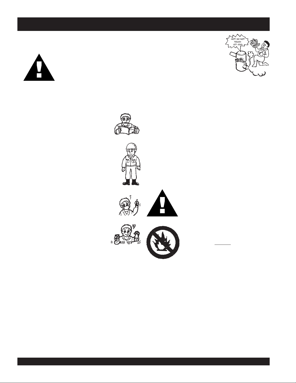
■
NEVER touch the hot exhaust
manifold, muffler or cylinder. Allow
these parts to cool before servicing
engine or generator.
■
High Temperatures – Allow the engine to cool before
adding fuel or performing service and maintenance
functions. Contact with
burns.
■
The engine of this generator requires an adequate free
flow of cooling air. Never operate the generator in any
enclosed or narrow area where free flow of the air is
restricted. If the air flow is restricted it will cause serious
damage to the generator or engine and may cause injury
to people. The generator engine gives off DEADLY carbon
monoxide gas.
CAUTIONCAUTION
CAUTION
CAUTIONCAUTION
hot
components can cause serious
:
■
NEVER operate this equipment when not feeling
well due to fatigue, illness or taking medicine.
■
NEVER operate this equipment under the
influence or drugs or alcohol.
■
NEVER use accessories or attachments,
which are not recommended by MQ Power for this
equipment. Damage to the equipment and/or injury to user
may result.
■
Manufacturer does not assume responsibility for any
accident due to equipment modifications.
■
Whenever necessary, replace nameplate, operation and
safety decals when they become difficult read.
■
Always check the machine for loosened threads or bolts
before starting.
■
■
Always refuel in a well-ventilated area,
away from sparks and open flames.
■
Always use extreme caution when
working with flammable liquids. When
refueling, stop the engine and allow it to
cool. DO NOT smoke around or near the
machine. Fire or explosion could result
from fuel vapors, or if fuel is spilled on a
hot engine.
NEVER operate the generator in an explosive atmosphere
or near combustible materials. An explosion or fire could
result causing severe
Topping-off to filler port is dangerous, as it tends to spill
fuel.
bodily harm or even death.
PAGE 6 — DCA-150SSJU — PARTS AND OPERATION MANUAL — REV. #3 (09/07/01)
Page 7
RULES FOR SAFE OPERATION
CAUTIONCAUTION
CAUTION
CAUTIONCAUTION
CAUTIONCAUTION
CAUTION
CAUTIONCAUTION
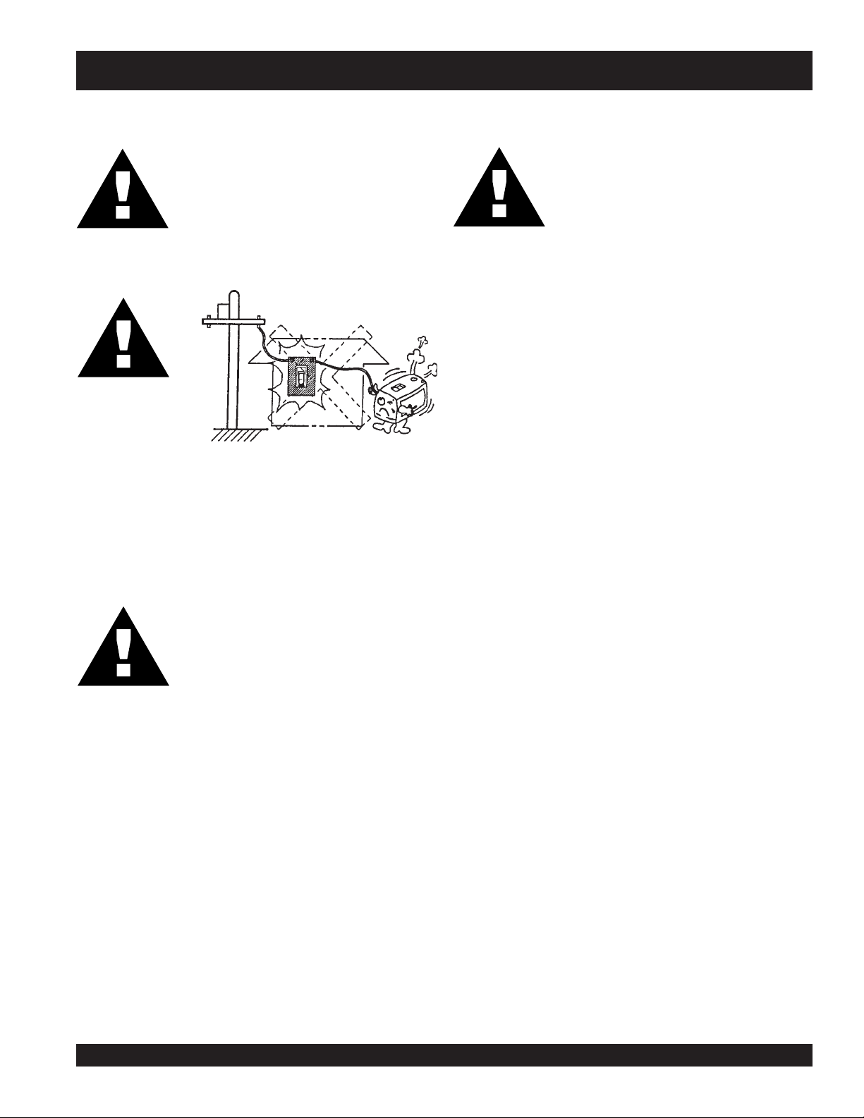
■
Backfeed to a utility system can cause electrocution
and.or property damage. Do not connect to any
building's electrical system except through an approved
device or after building main switch is opened.
:
NEVER touch output terminals during
operation. This is extremely dangerous.
Always stop the machine when contact with
the output terminals.
:
CAUTIONCAUTION
CAUTION
CAUTIONCAUTION
Radiator
1. Radiator Cap - Removing the radiator cap while the
2. Coolant Drain Plug - Removing the coolant drain plug
3. Engine Oil Drain Plug - Removing the engine oil drain
:
DO NOT touch or open any of the below
mentioned components while the
generator is running. Always allow
sufficient time for the engine and generator
to cool before performing maintenance.
engine is hot will result in high pressurized, boiling water
to gush out of the radiator, causing severe scalding to
any persons in the general area of the generator.
while the engine is hot will result in hot coolant to gush
out of the coolant drain plug, therefore causing severe
scalding to any persons in the general area of the
generator.
plug while the engine is hot will result in hot oil to gush
out of the oil drain plug, therefore causing severe
scalding to any persons in the general area of the
generator.
CAUTIONCAUTION
CAUTION
CAUTIONCAUTION
:
Never use damaged or worn cables when
connecting power tools or equipment to the
generator. Make sure power connecting
cables are securely connected to the
generator’s output terminals, insufficient
tightening of the terminal connections may
cause damage to the generator and
electrical shock.
DCA-150SSJU — PARTS AND OPERATION MANUAL — REV. #3 (09/07/01) — PAGE 7
Page 8
RULES FOR SAFE OPERATION
Battery
CAUTIONCAUTION
CAUTION
CAUTIONCAUTION
injury to the eyes and skin. To avoid eye irritation, always
wear safety glasses. Use well insulated gloves when picking
up the battery. Use the following guidelines when handling
the battery:
1. DO NOT drop the battery. There is the possibility of risk
that the battery may explode.
2. DO NOT expose the battery to open flames, sparks,
cigarettes etc. The battery contains combustible gases
and liquids. If these gases and liquids come in contact
with a flame or spark, an explosion could occur.
3. Always keep the battery charged. If the battery is not
charged a buildup of combustible gas will occur.
4. Always keep battery charging and booster cables in good
working condition. Repair or replace all worn cables.
5. Always recharge the battery in an open air environment,
to avoid risk of a dangerous concentration of combustible
gases.
6. In case the battery liquid (dilute sulfuric acid) comes in
contact with
immediately with plenty of water.
:
■
Never over fill the battery with water above
the upper limit.
The battery contains acids that can cause
clothing or skin
, rinse skin or clothing
■
NEVER Run engine without air filter. Severe engine
damage may occur.
■
Always service air cleaner frequently to prevent carburetor
malfunction.
■
Always disconnect the battery before performing service
on the generator.
■
Always be sure the operator is familiar with proper safety
precautions and operations techniques before using
generator.
■
Always store equipment properly when not in use.
Equipment should be stored in a clean, dry location out of
the reach of children.
■
DO NOT leave the generator running in the manual mode
unattended.
■
DO NOT allow unauthorized people to operate this
equipment.
■
Always read, understand, and follow procedures in
Operator’s Manual before attempting to operate equipment.
■
Refer to the
engine technical questions or information.
Loading and Unloading (Crane)
■
Before lifting, make sure the generator's lifting hook is
secure and that there is no apparent damage to the
generator itself (loose screws, nuts and bolts). If any
part is loose or damaged, please take corrective action
before lifting.
■
Always drain fuel prior to lifting.
■
Always make sure crane or lifting device has been
properly secured to the hook of guard frame on generator.
■
NEVER lift the machine while the engine is running.
John Deere Engine Owner's Manual
for
■
7. In case the battery liquid (dilute sulfuric acid) comes in
contact with your eyes, rinse eyes immediately with
plenty of water, then contact the nearest doctor or hospital,
and seek medical attention.
PAGE 8 — DCA-150SSJU — PARTS AND OPERATION MANUAL — REV. #3 (09/07/01)
Use adequate lifting cable (wire or rope) of sufficient
strength.
■
When lifting the generator, always use the balanced
center-point suspension hook and lift straight upwards.
■
NEVER allow any person or animal to stand underneath
the machine while lifting.
■
When loading the generator on a truck, be sure to use
the front and back frame bars as a means to secure the
generator during transport.
Page 9

Transporting
■
Always shutdown engine before transporting.
■
Tighten fuel tank cap securely.
■
Drain fuel when transporting generator over long distances
or bad roads.
■
Always tie-down the generator during transportation by
securing the generator.
■
If generator is mounted on a trailer, make sure trailer
complies with all local and state safety transportation
laws. See page 10 for basic towing procedures.
Emergencies
■
Always know the location of the nearest
and
first aid kit
Also know the phone numbers of the nearest
doctor
and
Maintenance Safety
■
NEVER lubricate components or attempt service on a
running machine.
. Know the location of the nearest telephone.
fire department
.
fire extinguisher
ambulance
,
RULES FOR SAFE OPERATION
■
Always allow the machine a proper amount of time to
cool before servicing.
■
Keep the machinery in proper running condition.
■
Fix damage to the machine immediately and always
replace broken parts.
■
Dispose of hazardous waste properly. Examples of
potentially hazardous waste are used motor oil, coolant,
fuel, and fuel filters.
■
DO NOT use plastic containers to dispose of hazardous
waste.
■
DO NOT pour waste, oil, coolant or fuel directly onto the
ground, down a drain or into any water source
DCA-150SSJU — PARTS AND OPERATION MANUAL — REV. #3 (09/07/01) — PAGE 9
Page 10
DCA-150SSJU — TOWING RULES FOR SAFE OPERATION
Towing Safety Precautions
CAUTION :CAUTION :
CAUTION :
CAUTION :CAUTION :
Check with your county or state safety
towing regulations department before towing
your generator.
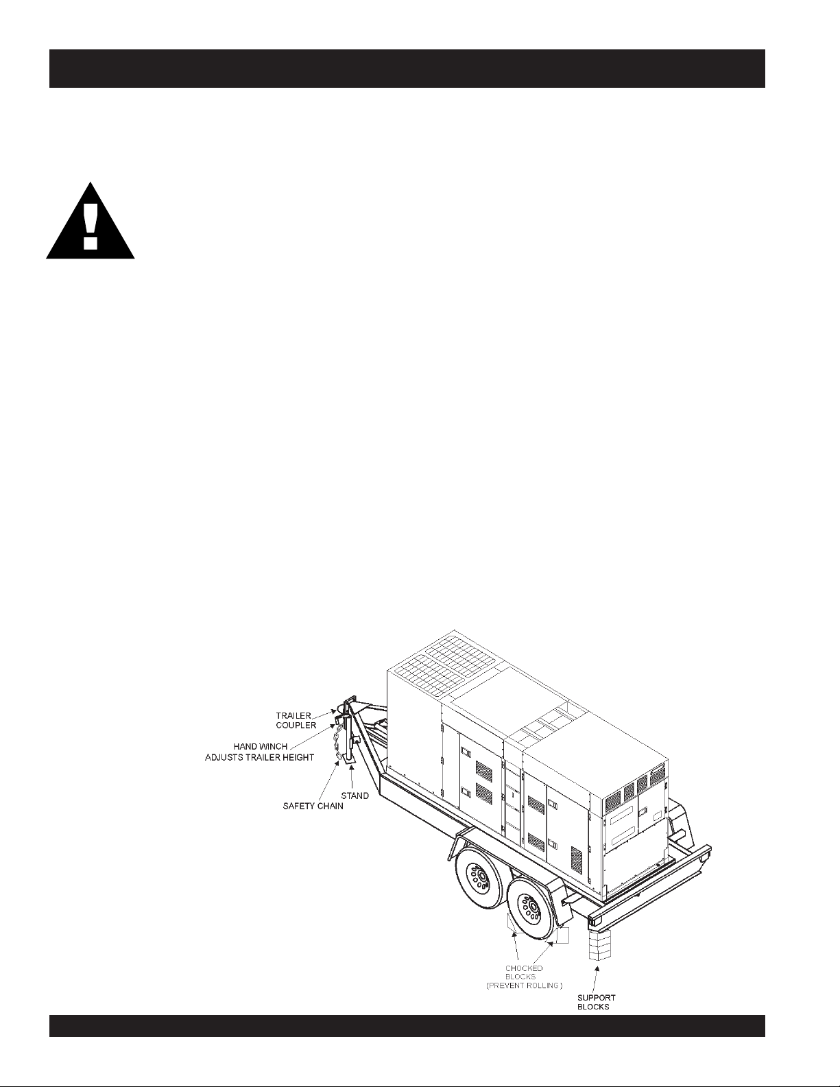
To reduce the possibility of an accident
while transporting the generator on public roads, always
make sure the trailer (Figure 1) that supports the generator
and the towing vehicle are in good operating condition and
both units are mechanically sound.
The following list of suggestions should be used when towing
your generator:
■
Make sure the hitch and coupling of the towing vehicle
are rated equal to, or greater than the trailer "gross vehicle
weight rating" (GVWR).
■
ALWAYS inspect the hitch and coupling for wear. NEVER
tow a trailer with defective hitches, couplings, chains
etc.
■
Check the tire air pressure on both towing vehicle and
trailer. Also check the tire tread wear on both vehicles.
■
ALWAYS make sure the vehicle and trailer directional,
backup, brake, and trailer lights are connected and
working properly.
■
The maximum speed for highway towing is 45 MPH
unless posted otherwise. Recommended off-road towing
is not to exceed 10 MPH or less depending on type of
terrain.
■
Place
rolling, while parked.
■
Place
prevent tipping, while parked.
■
Use the trailer’s hand winch to adjust the height of the
trailer, then insert locking pin to lock wheel stand in place,
while parked.
■
Avoid sudden stops and starts. This can cause skidding,
or jackknifing. Smooth, gradual starts and stops will
improve gas milage.
■
Avoid sharp turns to prevent rolling.
■
Remove wheel stand when transporting.
■
DO NOT transport generator with fuel in tank.
chocked blocks
support blocks
underneath wheel to prevent
underneath the trailer’s bumper to
■
ALWAYS make sure the trailer is equipped with a "Safety
Chain".
■
ALWAYS attach trailer’s safety chain to bumper of towing
vehicle.
Figure 1. Generator with Trailer
PAGE 10 — DCA-150SSJU — PARTS AND OPERATION MANUAL — REV. #3 (09/07/01)
Page 11

DCA-150SSJU — TRAILER-SAFETY GUIDELINES
CAUTION:CAUTION:
CAUTION:
CAUTION:CAUTION:
ALWAYS make sure the trailer is in good
operating condition. Check the tires for
proper inflation and wear. Also check the
wheel lug nuts for proper tightness.
Explanation of Chart:
This section is intended to provide the user with trailer service and maintenance information. The service and maintenance guidelines referenced in this section apply a wide
range of trailers. Remember periodic inspection of the trailer
will ensure safe towing of the equipment and will prevent
damage to the equipment and personal injury.
It is the purpose of this section to cover the major maintenance components of the trailer. The following trailer components will be discussed in this section:
Brakes
Tires
Lug Nut Torquing
Suspension
Electrical
Brake Troubleshooting Tables
Use the following definitions while reading Table 1.
1. Fuel Cell - Provides an adequate amount of fuel for
the equipment in use. Fuel cells must be empty when
transporting equipment.
2. Braking System - System employed in stopping the
trailer. Typical braking systems are electric, surge, hydraulic, hydraulic-surge and air.
7. Coupler - Type of hitch used on the trailer for towing.
8. Tire Size - Indicates the diameter of the tire in inches
(10,12,14, etc.), and the width in millimeters
(175,185,205, etc.). The tire diameter must match the
diameter of the tire rim.
9. Tire Ply - The tire ply (layers) number is rated in letters;
2-ply,4-ply,6-ply, etc.
10. Wheel Hub - The wheel hub is connected to the trailer’s
axle.
11. Tire Rim - Tires are mounted on a tire rim. The tire rim
must match the size of the tire.
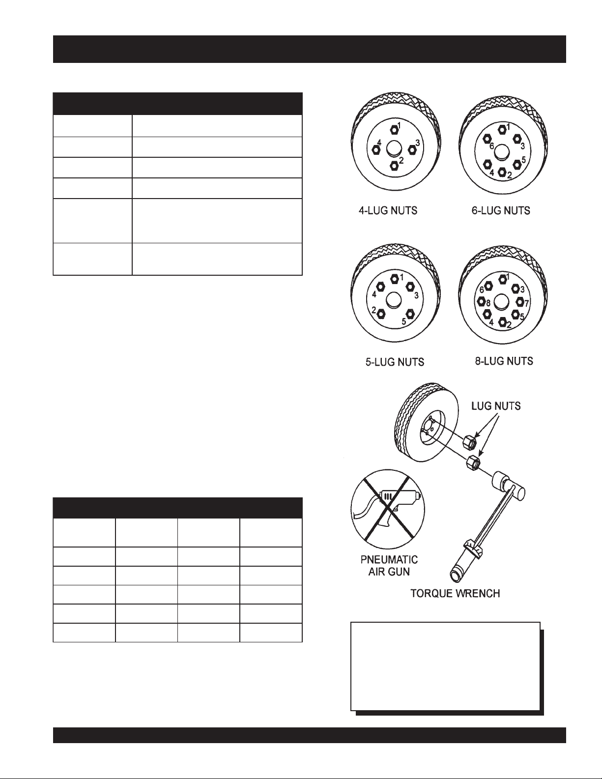
12. Lug Nuts - Used to secure the wheel to the wheel hub.
Always use a torque wrench to tighten down the lug
nuts. See Table 4 and Figure 5 for lug nut tightening and
sequence.
13. Axle - Indicates the maximum weight the axle can support in pounds, and the diameter of the axle expressed
in inches (see Table 3 on page 17). Please not that
some trailers have a double axle. This will be shown as
2-6000 lbs., meaning two axles with a total weight capacity of 6000 pounds.
14. Suspension - Protects the trailer chassis from shock
transmitted through the wheels. Types of suspension
used are leaf, Q-flex, and air ride.
15. Electrical - Electrical connectors (looms) are provided
with the trailer so the brake lights and turn signals can
be connected to the towing vehicle. See page 16 for
proper wiring connections.
16. Application - Indicates which units can be employed
on a particular trailer.
3. GVWR- Gross Vehicle Weight Rating (GVWR), is the
maximum number of pounds the trailer can carry, including the fuel cell (empty).
4. Frame Length - This measurement is from the ball
hitch to the rear bumper (reflector).
5. Frame Width - This measurement is from fender to
fender.
6. Jack Stand - Trailer support device with maximum
pound requirement from the tongue of the trailer.
DCA-150SSJU — PARTS AND OPERATION MANUAL — REV. #3 (09/07/01) — PAGE 11
Page 12

DCA-150SSJU — TRAILER-SPECIFICATIONS
snoitacificepS.1elbaT
LEDOM NOITACILPPA LEUF
LLEC
W01-RLRT ,522WDS
01-RLRT ,21GLT,01ACD
FX01-RLRT ,21-GLT,01ACD
W522-RLRT ,SREDLEW
004WLB-RLRT 004-WLBONCIRTCELESBL0072"451TSAM/W
X05-RLRT 52-ACDONONSBL0072"421"55.BL008
FX05-RLRT 52-ACDLAG14ONSBL0072"421"55.BL008
W07-RLRT 07,06-,54-ACDONEGRUSSBL0007"681"77.BL0002
X07-RLRT 07,06-,54-ACDTPOEGRUSSBL0007"831"66.BL00
FX07-RLRT 07,06-,54-ACDLAG35EGRUSSBL0007"831"66.BL0002
FX001-RLRT 521,001-ACDLAG051EGRUSCILUARDY
521/58-RLRT ,001,58-ACD
FX051-RLRT 08
FX022-RLRT 022-ACDLAG052EGRUSCILUARDYHSBL00041"222"38.BL
FX003-RLRT 003-ACDLAG052EGRUSCILUARDYHSBL00081"832"38.BL0005
FX004-RLRT 004-ACDLAG053CIRTCELESB
FX006-RLRT 008,006-ACDLAG055RIASBL00003"483"69.BL0005
XS008-RLRT 008,006-ACDLAG0
003WLT,052WGS
51-ACD
003-WLT,51ACD
S0007AD
S
521
1,051-ACDLAG002EGRUSCILUARDYHSBL06111"402"48.BL0005
ONONSBL0091"69"05.BL008
ONONSBL0091"69"05.BL00
LAG25ONSBL0091"69"05.BL008
ONONSBL0022"58"24.BL008
HSBL0007"091"67.BL0002
LAG541CILUARDYHSBL00001"681"77.BL0002
55RIASBL00003"483"69.BL0005
EKARB
METSYS
RWVG EMARF
HTGNEL
"421O/W
L00081"832"38.BL0005
EMARF
HTDIW
"55
)LLAT"87(
KCAJ
DNATS
LEEHWTLITLLUF
8
02
LEEHWTLITLLUF
LEEHWTLITLLUF
LEEHWTLITLLUF
008
.BL
LEEHWTLITLLUF
LEEHWTLITLLUF
WTLITLLUF
LEEH
DAPTALF
DAPTALF
DAPTALF
DAPTALF
DAPTALF
DAPTALF
0005
DAPTALF
DAPTALF
DAPTALF
DAPTALF
DAPTALF
PAGE 12 — DCA-150SSJU — PARTS AND OPERATION MANUAL — REV. #3 (09/07/01)
Page 13

DCA-150SSJU — TRAILER-SPECIFICATIONS
)t'noC(snoitacificepS.1elbaT
LEDOM RELPUOC SERIT SLEEHW ELXA SBUH NOISNEPSUS LACIRTCELE
W01-RLRT SSALCLLAB"2
01-RLRT SSALCLLAB"2
FX01-RLRT SSALCLLAB"2
W522-RLRT SSALCLLAB"2
WLB-RLRT
004
X05-RLRT SSALCLLAB"2CRL31-87B"05.4X"31.sbl0053
FX05-RLRT SSALCLLAB"2CRL31-87B"05.4X"31.sbl0053
W07-RLRT SSALCLLAB"2
X07-RLRT SSALCLLAB"2
FX07-RLRT SSALCLLAB"2
FX001-RLRT 6/5-2ELBATSUJDA
521/58-RLRT 6/5-2ELBATSUJDA
FX051-RLRT EYE
FX022-RLRT EYE"3
FX003-RLRT EYE"3
FX004-RLRT EYE"3
FX006-RLRT LEEHWHT5H5.7
RA008-RLRT LEEHWHT5H5.71R57/512TS
ELBATSUJDA2
ELBATSUJDA2
ELBATSUJDA2
ELBATSUJDA2
SSALCLLAB"2
SUJDA2
ELBAT
LBATSUJDA"3
E
ELBATSUJDA"3
ELBATSUJDA"3
EYE"3TPO
EYE"3TPO
LLAB"3E61-057
ELBATSUJDA
ELBATSUJDA
ELBATSUJDA
C31-571"05.4X"312X2#0022GUL5FAEL3/WMOOLERIW4
C31-571"5.4X"312X2#0022GUL5FAEL3TALFELOP4
C31-571"5.4X"312X2#0022GUL5FAEL3T
B31-571"5.4X312X2#0022GUL5XELFQTALFELOP4
C31-571"5.4X312X2#0022GUL5FAEL3TALFELOP4
"8/3-2
"8/3-2
C41-502
)4(SAIB
C41-502
4(SAIB
)
C41-502
)4(SAIB
C51-502
)4(SAIB
D51R57/522TS
)4(LAIDAR
)4(SAIB
E61R58/532TS
)4(LAIDAR
E61R58/532TS
)6(LAIDAR
E61R58/532TS
)6(LAIDAR
1R57/512TS
)8(LAIDAR
)8(LAIDAR
"5X"41.sbl0053
"5X"41sbl0053
"5X"41.sbl0053
"5.5X"41sbl0053
"6x"41sbl0006-)2(GUL6FAEL7MOOLERIW4
"7X"61sbl0006-)2(GUL8FAEL7MOOLERIW4
"7X"6
1sbl0007-)2(GUL8XELFQMOOLERIW4
"7X"61sbl0006-)2(GUL8XELFQMOOLERI
"7X"61.sbl0007-)3(GUL8XELFQMOOLERIW4
"7X"61sbl00001-)3(GUL8FAEL7MOOLERIW6
"7X"61sbl00
"3
"3
"3
"3
001-)3(GUL8EDIR-RIAMOOLERIW6
GUL5FAEL4REBBU
GUL5FAEL4REBBURELOP4
GUL5FAEL5REBBURELOP4
GUL5FAEL5REBBURELOP4
GUL5FAEL5REBBURELOP4
GUL5FAEL5MOOLERI
TALFELOP4
ALFELOP4
RELOP4
TALF
TALF
TALF
TALF
TALF
W4
W4
DCA-150SSJU — PARTS AND OPERATION MANUAL — REV. #3 (09/07/01) — PAGE 13
Page 14

DCA-150SSJU — TRAILER BRAKING SYSTEM
Brakes
If your trailer has a braking system, the brakes should be
inspected the first 200 miles of operation. This will allow
the brake shoes and drums to seat properly. After the first
200 mile interval, inspect the brakes every 3,000 miles. If
driving over rough terrain, inspect the brakes more
frequently.
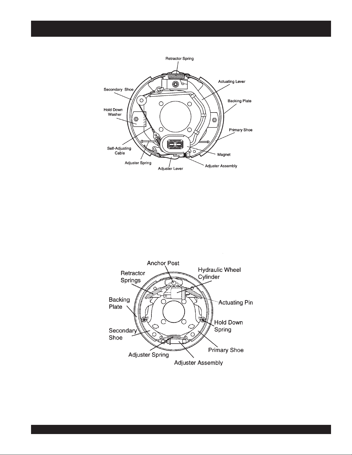
Electric Brakes
Electrically actuated brakes (Figure 2) are similar to
hydraulic brakes. The basic difference is that hydraulic
brakes are actuated by an electromagnet.
Listed below are some of the advantages that electric
brakes have over hydraulic brakes:
An electric brake system can be manually adjusted to
provide the corrected braking capability for varying road
and load conditions.
An electric brake system can be modulated to provide
more or less braking force, thus easing the brake load
on the towing vehicle.
An electric brake system has very little lag time between
the time the vehicle’s brakes are actuated and the
trailer’s brakes are actuated.
An electric brake system can provide an independent
emergency brake system.
Road testing is necessary in order to properly synchronize
the towing vehicle’s braking to the trailer’s braking. Brake
lockup, grabbiness, or harshness is due to lack of
synchronization between the tow vehicle and the trailer
being towed or under-adjusted brakes.
Before any brake synchronizations adjustments can be
made, the trailer brakes should be burnished-in by applying
the brakes 20-30 times with approximately a 20 m.p.h.
decrease in speed, e.g. 40 m.p.h. to 20 m.p.h.. Allow ample
time for brakes to cool between application. This allows
the brake shoes to slightly be seated into the brake drum
surface.
Figure 2 displays the major electric brake components that
will require inspection and maintenance. Please inspect
these components as required. Refer to Table 5 for electric
brake troubleshooting guidelines.
Electric Brake Adjustment
1. Place the trailer on jack stands. Make sure the jack
stands are placed on secure level ground.
2. Check the wheel and drum for free rotation.
3. Remove the adjusting hole cover from the adjusting
slot at the bottom brake backing plate.
4. With a screwdriver or standard adjusting tool, rotate
the star wheel of the adjuster assembly to expand the
brake shoes.
5. Adjust the brake shoes outward until the pressure of
the lining against the wheel drum makes the wheel
difficult to turn.
6. Rotate the star wheel in the opposite direction until the
wheel rotates freely with slight lining drag.
7. Replace the adjusting hole cover and lower the trailer
to the ground.
8. Repeat steps 1 through 6 on the remaining brakes.
PAGE 14 — DCA-150SSJU — PARTS AND OPERATION MANUAL — REV. #3 (09/07/01)
Page 15
DCA-150SSJU — TRAILER BRAKING SYSTEM
Figure 2. Electrical Brake Components
Hydraulic/Air/Surge Brakes
Hydraulic brakes (Figure 3) should not require any special
attention with the exception of routine maintenance such
as shoe and lining replacement. These brakes can be
adjusted in the same manner as electric brakes. Brake
lines should be periodically checked for cracks, kinks, or
blockage.
Figure 3 below displays the major hydraulic/air/surge brake
components that will require inspection and maintenance.
Inspect these components as required using steps 1
through 6 as referenced in the electric brake adjustments
section. Reference Table 6 for hydraulic brake
troubleshooting guidelines.
Figure 3. Hydraulic Brake Components
DCA-150SSJU — PARTS AND OPERATION MANUAL — REV. #3 (09/07/01) — PAGE 15
Page 16
DCA-150SSJU — TRAILER TIRES & SUSPENSION
Tires/Wheels/Lug Nuts
Tires and wheels are a very important and critical
components of the trailer. When specifying or replacing
the trailer wheels it is important the wheels, tires, and axle
are properly matched.
CAUTION:CAUTION:
CAUTION:
CAUTION:CAUTION:
DO NOT attempt to repair or modify a
wheel. DO NOT install an inner tube to
correct a leak through the rim. If the
rim is cracked, the air pressure in the
inner tube may cause pieces of the rim
to explode (break off) with great force and cause serious
eye or bodily injury.
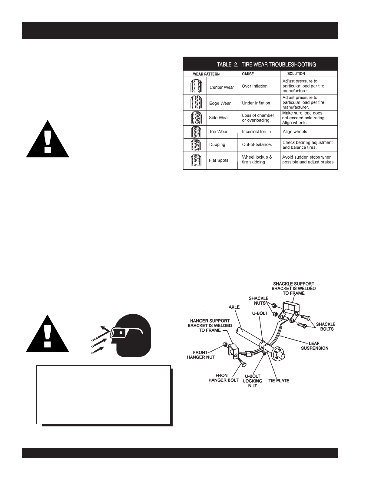
Suspension
The leaf suspension springs and associated components
Tire Wear/Inflation
Tire inflation pressure is the most important factor in
preserving tire life. Pressure should be checked cold before
operation. DO NOT bleed air from tires when they are hot.
Check inflation pressure weekly to insure the maximum
tire life and to prevent premature tread wear.
Table 2 (Tire Wear Troubleshooting) will help pinpoint the
causes and solutions of tire wear problems.
(Figure 4) should be visually inspected every 6,000 miles
for signs of excessive wear, elongation of bolt holes, and
loosening of fasteners. Replace all damaged parts
(suspension) immediately. Torqued suspension components
as detailed in Table 3.
CAUTION:CAUTION:
CAUTION:
CAUTION:CAUTION:
NOTE
ALWAYS wear safety glasses when removing
or installing force fitted parts. Failure to
comply may result in serious injury.
PAGE 16 — DCA-150SSJU — PARTS AND OPERATION MANUAL — REV. #3 (09/07/01)
Figure 4. Suspension Components
Page 17
metI ).sbL-.tF(euqroT
TLOB-U"8/353-XAM03-NIM
TLOB-U"61/706-XAM54-NIM
TLOB-U"2/106-XAM54-NIM
DCA-150SSJU — TRAILER TIRES & SUSPENSION
stnemeriuqeReuqroTnoisnepsuS.3elbaT
SHACKLE BOLT
SPRING EYE BOLT
SHOULDER TYPE
SHACKLE BOLT
SNUG FIT ONLY.PARTS MUST ROTATE FREELY
LOCKING NUTS OR COTTER PINS ARE PROVIDED TO
-
RETAIN NUT
BOLT ASSEMBLY
.
05-XAM03-NIM
.
Lug Nut Torque Requirements
It is extremely important to apply and maintain proper wheel
mounting torque on the trailer. Be sure to use only the
fasteners matched to the cone angle of the wheel. Proper
procedure for attachment of the wheels is as follows:
1. Start all wheel lug nuts by hand.
2. Torque all lug nuts in sequence. See Figure 5. DO
NOT torque the wheel lug nuts all the way down. Tighten
each lug nut in 3 separate passes as defined by Table
4.
3. After first road use, retorque all lug nuts in sequence.
Check all wheel lug nuts periodically for continued safe
operation.
stnemeriuqeReuqroTeriT.4elbaT
eziSleehWssaPtsriF
SBL-TF
"2152-0204-5356-05
"3152-0204-5356-05
"4152-0206-05021-09
5152-0206-05021-09
"
"6152-0206-05021-09
ssaPdnoceS
SBL-TF
DCA-150SSJU — PARTS AND OPERATION MANUAL — REV. #3 (09/07/01) — PAGE 17
ssaPdrihT
SBL-TF
Figure 5. Lug Nut Tightening Sequence
NOTE
NEVER use an pneumatic air gun to
tighten wheel lug nuts.
Page 18
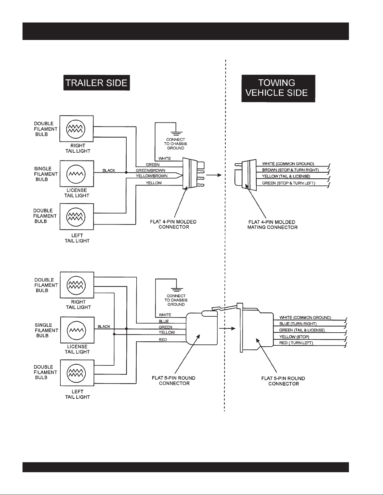
DCA-150SSJU — TRAILER WIRING DIAGRAM
NOTE:
LIGHTS ARE ORIENTED FROM THE DRIVER’S SEAT
PAGE 18 — DCA-150SSJU — PARTS AND OPERATION MANUAL — REV. #3 (09/07/01)
Page 19

DCA-150SSJU — TRAILER-BRAKE TROUBLESHOOTING
gnitoohselbuorTekarBcirtcelE.5elbaT
motpmyS esuaCelbissoP noituloS
tnettimretnIrosekarBoN
sekarB
sekarBrosekarBkaeW
ediSenOotlluP
gnikcoLrotneb,esoolstnenopmocekarB
sekarB
sekarBysioN?de
?seriwnekorbrostiucricnepoynA.tcerrocdnadniF
?stiucrictrohsynA.tcerr
?rellortnocytluaF.tcerrocdnatseT
?snoitcennocesoolynA.riaperdnadniF
?eruceseriwdnuorG.erucesdnadn
?sgninilrostengamnolioroesaerG.ecalperronaelC
?dedorrocsnoitcennoCtcerr
?devoorgroderocssmurdekarB.ecalperroenihcaM
?dezinorhcnyssekarB.tcerroC
?nekorb
?dnuor-fo-tuosmurdekarB.ecalpeR
tacirbulmetsyS.etacirbuL
ocdnadniF
iF
ocdnanaelC
.noisorrocfoesuac
.stnenopmocecalpeR
?tcerrocstnenopmocekarB.tcerrocdnaecalpeR
sekarBgniggarD?detsujdaleehwehtfosgnira
DCA-150SSJU — PARTS AND OPERATION MANUAL — REV. #3 (09/07/01) — PAGE 19
eB.tsujdA
Page 20
DCA-150SSJU — TRAILER-BRAKE TROUBLESHOOTING
gnitoohselbuorTekarBciluardyH.6elbaT
motpmyS esuaCelbissoP noituloS
sekarBoN?deknikronekorbenilekarB.ecalperroriapeR
otlluPsekarBrosekarBkaeW
ediSenO
sekarBgnikcoL?nekorbrotneb,esoolstnenopmocekarB.stnenopmocecalpeR
sekarBysioN?detacirbulmetsyS.etacirbuL
sekarBgniggarDthgirnirotcerrocssenkcihtgninilekarB
rB.ecalperrohsinrubeR
erusserperiT.yllauqeseritllaetalfnI
w
?dezalggninileka
?dedaolrevoreliarT.thgiewtcerroC
?devoorgroderocssmurdekarB.ecalperroenihcaM
?tcerroc
?elxaemasehtnodehctamnuseriT.serithctaM
?dnuor-fo-tuosmurdekarB.ecalpeR
?
tcerrocstnenopmocekarB.tcerrocdnaecalpeR
?noitisopgnor
?diulftcerrocrodiulfekarbhguonEstraprebburecalpeR
dnaseohswenllatsnI
.sgninil
.diulf4todhtiwllif
PAGE 20 — DCA-150SSJU — PARTS AND OPERATION MANUAL — REV. #3 (09/07/01)
Page 21
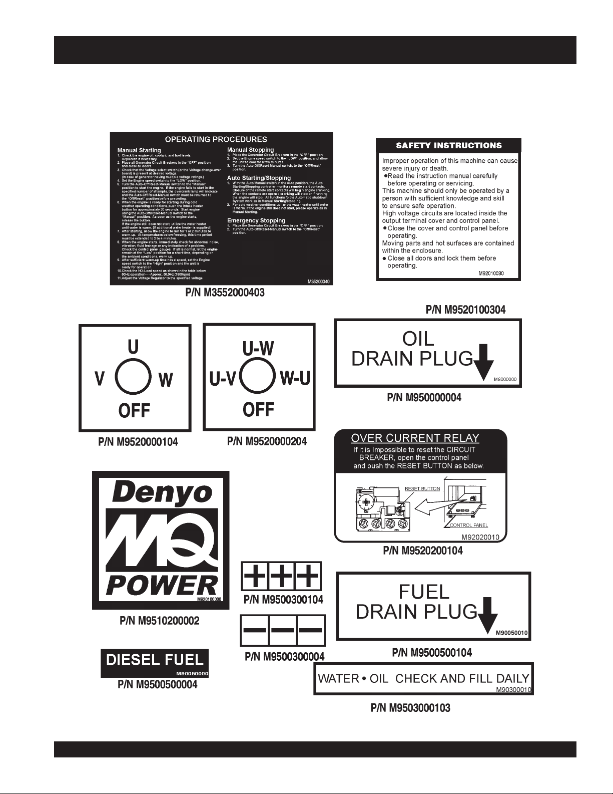
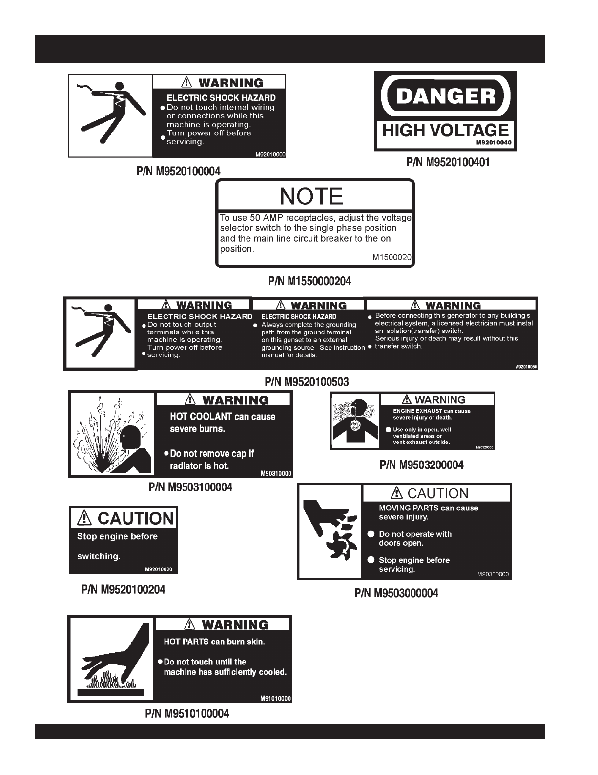
DCA-150SSJU — GENERATOR DECALS
The DCA-150SSJU generator is equipped with a number of safety decals. These decals are provided for operator safety
and maintenance information. The illustration below and on the preceding pages show the decals as they appear on the
machine. Should any of these decals become unreadable, replacements can be obtained from your dealer.
DCA-150SSJU — PARTS AND OPERATION MANUAL — REV. #3 (09/07/01) — PAGE 21
Page 22
DCA-150SSJU — GENERATOR DECALS
PAGE 22 — DCA-150SSJU — PARTS AND OPERATION MANUAL — REV. #3 (09/07/01)
Page 23

DCA-150SSJU — SPECIFICATIONS
ledoMUJSS051-ACD
snoitacificepS.7elbaT
snoitacificepSrotareneG
epyT
mrA
esahP3 elgniS
egatloVV084roV0
deepSmpr0081
egatloVV021
tuptuO)2xWK4.2(WK8.4
noitcennoCeruta
tuptuOybdnatS)WK231(AVK561WK69
tuptuOemirP)WK021(AVK051WK78
42V021/042
ycneuqerFzH06
rotcaFrewoP8.01
rewoPCA.xuAzH06,esahPelgniS
lartueNhtiwratSgaZgiZ
rotarenegsuonorhcnys
epytdetcetorpnepo,detalitnevfles,dleifgnivloveR
snoitacificepSenignE
ledoM100FT1806EREEDNHOJ
epyTdegrahc-obrut,noitcejnitcerid,delooc-retaw,elcyc-4
srednilyCfo.oNsrednilyc6
eko
rtSxeroB)mm921xmm611(.ni80.5x.ni75.4
tuptuOdetaRmpr0081/PH091
tnemecalpsiD)cc0018(.ni.uc494
gnitratScirtcelE
yticapaCtnalooC)sretil13(.lag2.8
yticapaCliOebuL)sretil23(.lag5.8
tarh/)L7.63(.lag7.9 lluf
aol
d
noitpmusnoCleuF
yrettaB1xHA522-V21
leuFle
tarh/)L02(.lag3.5 2/1
daol
tarh/)L3.82(.lag5.7 daol4/3
tarh/)L2.31(.lag5.3 daol4/1
uFleseiD2#
DCA-150SSJU — PARTS AND OPERATION MANUAL — REV. #3 (09/07/01) — PAGE 23
Page 24

DCA-150SSJU — GENERAL INFORMATION
DCA-150SSJU FAMILIARIZATION
Generator
The MQ Power Model DCA-150SSJU is a 120 kW
that is designed as a high quality portable (requires a trailer
for transport) power source for telecom sites, lighting
facilities, power tools, submersible pumps and other
industrial and construction machinery.
Engine Control Panel
The “Engine Control Panel” is provided with the following:
z
Tachometer
z
Water Temperature Gauge
z
Oil Pressure Gauge
z
Charging Ammeter Gauge
z
Engine Speed Switch
z
Auto/On/Off Engine Controller(if applicable)
z
Pre-Heat Button
z
Pre-Heat Lamp
z
Key Ignition starter
z
Fuel Gauge
z
Panel Light
z
Panel Light Switch
Generator Control Box
The “Generator Control Box” is provided with the following:
z
Output Voltage Adjustment Knob
z
Frequency Meter (Hz)
z
AC Ammeter (Amps)
z
AC Voltmeter (Volts)
z
Ammeter Change-Over Switch
z
Voltmeter Change-Over Switch
z
Main Circuit Breaker 400 amps
z
Over-Current Relay
z
Voltage Selector Switch
Output Terminal Panel
The “Output Terminal Panel” is provided with the following:
z
Three 240 output receptacles, 50 amp
z
Two 120V output receptacles, 20 amp
z
3 Circuit Breakers 240V @50 amps
z
2 GFCI Circuit Breakers 120V@ 20amps
generator
Open Delta Excitation System
The DCA-150SSJU generator is equipped with the state of
the art "
system consist of an electrically independent winding wound
among stationary windings of the AC output section.
There are four leads: A, B, C and D. During light loads, the
power to the
from the leads parallel connections of B&C. When loads
increase, the AVR switches and accepts power from leads
A&D. The output of leads A&D increase proportionally with
load. This of adding the voltages to each phase provides
better voltage response during heavy loads.
The connections of the AVR to the AC output windings are
for sensing only. No power is required from these windings.
The open-delta design provides virtually unlimited excitation
current, offering maximum motor starting capabilities. The
excitation does not have a "
according the demands of the required load.
Engine
The DCA-150SSJU is powered by a 4 cycle, water cooled,
turbocharged John Deere 6081TF001 diesel
engine is designed to meet every performance requirement
for the generator. Reference Table 7, page 23 for engine
specifications.
In keeping with MQ Power's policy of constantly improving
its products, the specifications quoted herein are subject to
change without prior notice.
The basic controls and indicators for the DCA-150SSJU
generator are addressed on the following pages.
Electronic Governor System
The electronic governor system is made up of two parts, an
electronic controller that monitors frequency variation as the
load increases and decreases and an electronic actuator
that controls the engine throttle. The frequency is regulated
at ±0.25 to help protect sensitive equipment.Engine
Open-Delta
" excitation system. The open delta
Automatic Voltage Regulator
fixed ceiling
(AVR) is supplied
" and responds
engine. This
PAGE 24 — DCA-150SSJU — PARTS AND OPERATION MANUAL — REV. #3 (09/07/01)
Page 25

NOTE PAGE
DCA-150SSJU — PARTS AND OPERATION MANUAL — REV. #3 (09/07/01) — PAGE 25
Page 26
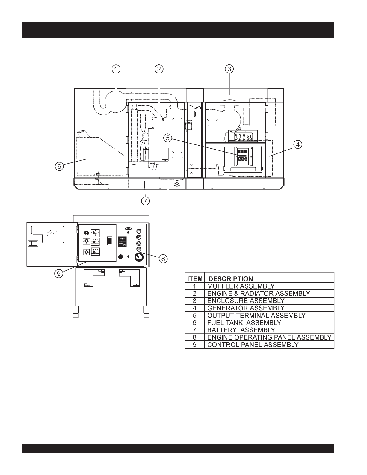
DCA-150SSJU
___
MAJOR COMPONENTS
Figure 6. Major Components
PAGE 26 — DCA-150SSJU — PARTS AND OPERATION MANUAL — REV. #3 (09/07/01)
Page 27
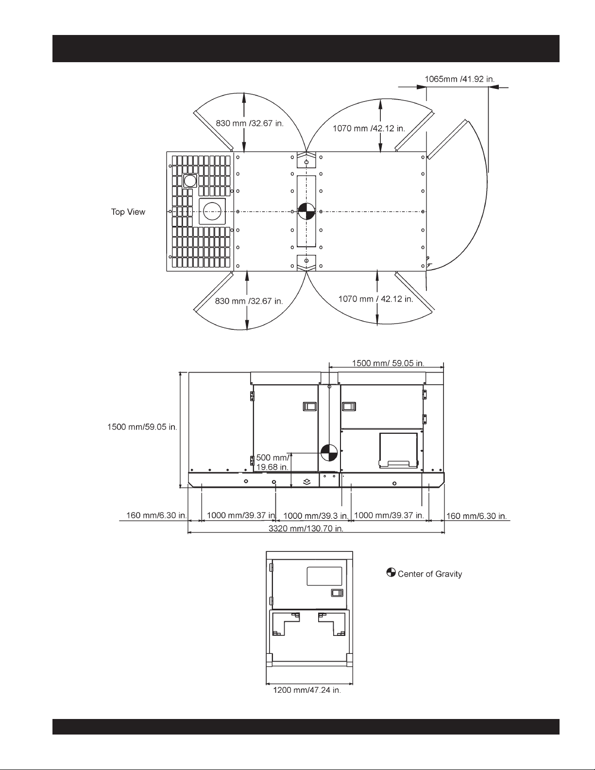
DCA-150SSJU — DIMENSIONS
Figure 7. Dimensions
DCA-150SSJU — PARTS AND OPERATION MANUAL — REV. #3 (09/07/01) — PAGE 27
Page 28
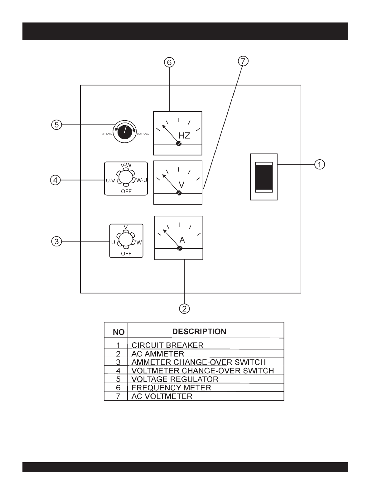
DCA-150SSJU — CONTROL PANEL
Figure 8. Control Panel
PAGE 28 — DCA-150SSJU — PARTS AND OPERATION MANUAL — REV. #3 (09/07/01)
Page 29

DCA-150SSJU — CONTROL PANEL
The definitions below describe the controls and functions of
the DCA-150SSJU "
1. Main Circuit Breaker – This three-pole, 400 amp main
breaker is provided to protect the UVW voltage output
terminals from overload.
2. AC Ammeter – Indicates the amount of current the
load is drawing from the generator.
3. Ammeter Change-Over Switch – This switch allows
the AC ammeter to indicate the current flowing to the
load connected to any phase of the output terminals, or
to be switched off.
4. Voltmeter Change-Over Switch – This switch allows
the AC Voltmeter to indicate phase to phase voltage
between any two phases of the output terminals, or to
be switched off.
5. Voltage Regulator Control – Allows adjustment of the
generator’s output voltage.
Control Panel
" (Figure 8).
6. Frequency Meter – Indicates the output frequency in
hertz (Hz). Normally 63Hz. with a calibration difference
of +0.5% with the mechanical governor or +0.25% with
the electronic governor.
7. AC Voltmeter – Indicates the single phase output
voltage present at the UVW terminals.
DCA-150SSJU — PARTS AND OPERATION MANUAL — REV. #3 (09/07/01) — PAGE 29
Page 30
DCA-150SSJU — ENGINE OPERATING PANEL
S/N 7600091~
Figure 9. Engine Operating Panel
PAGE 30 — DCA-150SSJU — PARTS AND OPERATION MANUAL — REV. #3 (09/07/01)
Page 31

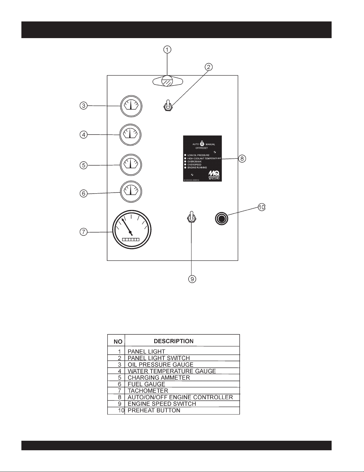
DCA-150SSJU — ENGINE OPERATING PANEL (With Engine Controller)
The definitions below describe the controls and functions of
the DCA-150SSJU "
Number greater than7600090 (Figure 9).
1. Panel light - Normally used in dark places or at night.
When activated, panel will luminate. When the generator
is not in use, turn the panel light switch to the ‘OFF’
position.
2. Panel light switch- When activated, will turn on panel
light.
3. Oil Pressure Gauge – During normal operation this
gauge be should read 42 to 71 psi. When starting the
generator the oil pressure may read slightly higher, but
after the engine warms up the oil pressure should return
within that range.
4. Water Temperature Gauge – During normal operation
this gauge be should read 165
5. Charging Ammeter Gauge – Indicates the current
being supplied by the engine’s alternator which provides
current for generator’s control circuits and battery
charging system.
Engine Operating Panel
o
-203oF.
" with Serial
using variable resistive values from the oil pressure
sending unit. This is considered a
C. High Coolant Temperature – Indicates the engine
temperature has exceeded 215°F. The engine
temperature is detected using variable resistive values
from the temperature sending unit. This is considered a
major
D. Overcrank Shutdown – Indicates the unit has
attempted to be started a pre- programmed number of
times, and has failed to start. The number of cycles
and duration are programmable. It is pre-set at 3 cycles
with a 10 second duration. This is considered a
fault.
E. Overspeed Shutdown – Indicates that the engine is
running at an unsafe speed. This is considered a
fault.
F. Engine Running – Indicates that engine is running
at a safe operating speed.
9. Throttle Handle - This handle controls the speed of
the engine (low or high).
fault.
major
fault.
major
major
6. Fuel Gauge - Indicates amount of diesel fuel available.
7. Tachometer – Indicates engine speed in RPM’s for 60
Hz operation. This meter should indicate 1800 RPM’s
when the rated load is applied. In addition a built in hour
meter will record the number of operational hours that
the generator has been in use.
8. Auto Start Controller – This controller will indicated
with LEDs that an engine fault has been detected. When
a fault has been detected the controller will evaluate
the fault will shutdown the generator if it may be
damaging to the engine.
A. Off/Manual/Auto Switch – This switch controls the
running of the generator. If this switch is left in the "OFF"
position, the generator will not run. When this switch is
set to the
immediately.
If the generator is to be connected to a building's AC
power source via a transfer switch (isolation), place the
switch in the
will monitor the AC line output from the building's power
source.
manual
auto
position, the generator will start
position. In this position the generator
10. Pre-Heat Button – This is to pre-heat the engine under
extreme cold conditions.
B. Low Oil Pressure – Indicates the engine pressure
has fallen below 15 psi. The oil pressure is detected
DCA-150SSJU — PARTS AND OPERATION MANUAL — REV. #3 (09/07/01) — PAGE 31
Page 32

DCA-150SSJU — ENGINE OPERATING PANEL
UP TO S/N760090
Figure 10. Engine Operating Panel
PAGE 32 — DCA-150SSJU — PARTS AND OPERATION MANUAL — REV. #3 (09/07/01)
Page 33

DCA-150SSJU — ENGINE OPERATING PANEL (With Key Switch)
The definitions below describe the controls and functions of
the DCA-150SSJU "
10).
1. Panel light - Normally used in dark places or at night.
When activated, panel will luminate. When the generator
is not in use, turn the panel light switch to the ‘OFF’
position.
2. Panel light switch- When activated, will turn on control
panel light.
3. Oil Pressure Gauge – During normal operation this
gauge be should read between 42 to 71 psi. When
starting the generator the oil pressure may read slightly
higher, but after the engine warms up the oil pressure
should return within the normal range.
4. Water Temperature Gauge – During normal operation
this gauge be should read between 165o to 203o F.
5. Charging Ammeter Gauge – Indicates the current
being supplied by the engine’s alternator which provides
current for generator’s control circuits and battery
charging system.
Engine Operating Panel
" (Figure
6. Fuel Gauge - Indicates amount of diesel fuel available.
7. Tachometer – Indicates engine speed in RPM’s for 60
Hz operation. This meter should indicate 1800 RPM’s
when the rated load is applied. In addition a built in hour
meter will record the number of operational hours that
the generator has been in use.
8. Ignition Switch - This switch is used to turn on or off
the engine with a key.
9. Throttle Handle - This handle controls the speed of
the engine (low or high).
10. Pre-Heat Button – This is to pre-heat the engine under
extreme cold conditions.
11. Water Temperature Indicator - This light indicates the
water temperature is too high and will shut down the
engine.
12. Oil Pressure Indicator - This light indicates the oil
pressure is either too high or too low and will shut down
the engine.
DCA-150SSJU — PARTS AND OPERATION MANUAL — REV. #3 (09/07/01) — PAGE 33
Page 34

DCA-150SSJU — OUTPUT TERMINAL PANEL OVERVIEW
OUTPUT TERMINAL PANEL FAMILIARIZATION
Output Terminal Panel
The “Output Terminal Panel” is provided with the following:
z
Three 240 output receptacles, 50 amp
z
Two 120V output receptacles, 20 amp
z
3 Circuit Breakers 240V @50 amps
z
2 GFCI Circuit Breakers 120V@ 20amps
Output Terminal Panel
The Output Control Panel (See Figure 14) is located on the
right hand side (left from control panel) of the generator.
The UVW lugs are protected by a face plate cover that can
be secured in the close position by a pad lock. (See Figure
11).
FIGURE 11. Output Terminal Cover
120 Volt Receptacle
Two GFCI Duplex Nema 5-20R (120V, 20 Amp) receptacle
is provided on the output terminal. This receptacle can be
used anytime the generator is in operation. The receptacle
is controlled by the circuit breaker located on the control
panel.
Connecting Load
Loads can be connected to the generator by the UVW Lugs or
the convenience receptacles. (See Figure 13). Make sure to
read the operation manual before attempting to connect a load
to the generator.
Circuit Breakers
To protect the generator from an overload, a 3-pole, 400 amp,
main
circuit breaker is provided to protect the UVW output
terminals from overload. In addition two single-pole, 20 amp
GFCI
circuit breakers are provided to protect the GFCI
receptacles from overload. Three 50 amp
have also been provided to protect the load side of the
generator from overload. Make sure to switch
breakers to the "OFF" position prior to starting the engine.
Maximum Output
The entire load connected to the UVW Lugs, all four slots in the
duplex receptacles, and the must not exceed 132 kW in
standby or 120 kW in prime output.
FIGURE 13. Connecting Load
load
circuit breakers
ALL
circuit
Pressing the reset button resets the receptacle after being
tripped. Pressing the "Test Button" (See Figure 12) in the
center of this receptacle will check the GFCI function. The
receptacle should be tested at least once a month.
FIGURE 12. GFCI Test Button
PAGE 34 — DCA-150SSJU — PARTS AND OPERATION MANUAL — REV. #3 (09/07/01)
Twist Lock Dual Voltage Receptacles - To use these
receptacles, place the voltage selector switch in the single
phase 240/120 voltage position and adjust the output
voltage to 240 volts with the voltage regulator on the
Control Panel. Place the voltmeter change-over switch to
the U-W position and the ammeter change-over switch to
the U or W to read the output.
Page 35

DCA-150SSJU — OUTPUT TERMINAL PANEL OVERVIEW
NOTE
Legs O and Ground are
considered Bonded Grounds.
FIGURE 14. Output Terminal Panel
DCA-150SSJU — PARTS AND OPERATION MANUAL — REV. #3 (09/07/01) — PAGE 35
Page 36

DCA-150SSJU — OUTPUT TERMINAL PANEL OVERVIEW
Output Terminal Panel Available Voltages
A wide range of voltages are available to supply load to
many different applications. Voltages may be selected by
using the voltage selector switch and how you hookup
Maximum Amps
The following table show the maximum amps the entire
generator can provide. Do not exceed the maximum amps
listed. (See Table 9)
your hard wire connection to the generator. To obtain some
of the voltages listed, fine adjustment with the Voltage
Regulator on the control panel is necessary. See the table
below (Table 8) for a list of available voltages the generator
is able to supply.
ELBALIAVASEGATLOV.8ELBAT
EGATLOVESAHP3
)ELBAHCTIWS(
ESAHPELGNIS
)ELBAHCTIWS(
TLOV802TLOV022TLOV042TLOV614TLOV044TLOV084
TLOV021TLOV721TLOV
931TLOV042TLOV452TLOV772
Voltage Selector Switch
The voltage selector switch is located above the UVWO
Hard Wire Hookup Panel. It has been provided for ease of
voltage selection.
CAUTION :
:ledoMUJSS051ACD
detaR
egatloV
esahPelgniS
tloV021
esahPelgniS
tloV042
esahPeerhT
tloV042
esahPeerhT
tloV084
spmAmumixaM.9elbaT
spmAmumixaM
)eriw4(spma3.333
)eriw4(spma7.661
spma163
spma081
NEVER switch Voltage Selector Switch
position while the engine is engaged.
Receptacle Use
When the UVWO terminals are providing power, the
receptacle power available decrease. Do not exceed
receptacle power available listed on Table 10.
Voltage Selector Switch Locking Button
The voltage selector switch has a locking button to protect
the generator and generator load from being switched while
the engine is running. To lock the Voltage Selector Switch,
press in the red button located on the Voltage Selector
Switch, and use a pad lock to hold it into this position.
Over Current Relay
An over current relay is connected to the circuit breaker.
In an over current situation, both the circuit breaker and
the over current relay may trip. If the circuit breaker can
not be reset, the reset button on the over current relay
must be pressed. The over current relay is located in the
control box.
esUelcatpeceR.01elbaT
elcatpeceR
esUnirewoP
rewoP
elbaliavA
V021/042
V084/042
esahP-3
AVKWKWK
051780
6418.582.1
2416.484.2
esahPelgniS
tsiwTro
9636SCkcoL
ICFG
xelpuD
AMEN
V021R02-5
8314.386.3
3312.288.4
PAGE 36 — DCA-150SSJU — PARTS AND OPERATION MANUAL — REV. #3 (09/07/01)
Page 37

DCA-150SSJU — OUTPUT TERMINAL PANEL OVERVIEW
How to read the output terminal gauges.
The gauges and knobs on the control panel DO NOT effect
the generator output in any fashion. They are there to
simply help the operator observe how much power is being
supplied produced at the UVWO legs.
When the voltage selector switch is in the 240/120V
position (see Figure 15), place the AC Voltmeter Changeover switch to the W-U position and the AC ammeter
Change-over Switch to the U or W position to read the
output on the selected leg.
FIGURE 18. AC Ammeter
Change-over Switch
(Reading the U leg on the
output terminal panel)
FIGURE 19. AC Ammeter
(Amp reading on U lug)
NOTE
FIGURE 15. Voltage Selector Switch 240/120V Single Phase
Position
FIGURE 16. AC Voltmeter
Change-over switch
(Reading the W-U leg on
the output terminal panel)
FIGURE 17. AC Voltmeter
Gauge
(Volt reading on W-U Lug)
When using plural single phase
voltages, make sure to balance
the load on each of the single
phase legs.
DCA-150SSJU — PARTS AND OPERATION MANUAL — REV. #3 (09/07/01) — PAGE 37
Page 38

DCA-150SSJU — OUTPUT TERMINAL PANEL OVERVIEW
240/120V Hard Wire Hookup
The output terminal panel, when suppling single phase 120
volts, will provide three legs available with 333.3 amps each
on three different circuits. (See Figure 21 below.) The
voltage selector switch must be set at the single phase 240/
120V position. (See Figure 20 below.)
The output terminal panel, when suppling single phase 240
volts, will provide one leg only with 166.7 amps available.
(See Figure 21 below.) The voltage selector switch must be
set at the single phase 240/120V position. (See Figure 20
below.)
480/240V Hard Wire Hookup
The output terminal panel, when suppling three phase 240
volts, will provide one circuit available at 361 amps with any
two wires plus the ground. (See Figure 23 below.) The voltage
selector switch must be set at the three phase 480/277V
position. (See Figure 22 below.)
The output terminal panel, when suppling 3 phase 480 volts,
will provide one circuit available at 180 amps available with
all three wires plus ground. (See Figure 23 below.) The
voltage selector switch must be set at the three phase 480/
277V position. (See Figure 22 below.)
FIGURE 20. Voltage Selector Switch 240/120V Single Phase
Position
FIGURE 21. Hard Wire Hookup at 240/120V Position
FIGURE 22. Voltage Selector Switch 480/277V Three Phase
Position
FIGURE 23. Hard Wire Hookup at 480/240V Position
PAGE 38 — DCA-150SSJU — PARTS AND OPERATION MANUAL — REV. #3 (09/07/01)
Page 39

DCA-150SSJU — OUTPUT TERMINAL PANEL OVERVIEW
Voltage Selector Switch- 3 Phase 480/277V Position
The following are additional voltages available when the
voltage selector switch is in the 3 phase 480/277V
position. (See Figure 24 below.)
Single Phase: 480V, 440V, or 416 Volt
The following connection, with the voltage selector switch
locked into the 3 phase 480/277V position (See Figure 27),
can offer SINGLE PHASE power at 480V, 440V, or 416V.
After hooking up the hard wires to the lugs as shown in
Figure 27 below, 480V will be the voltage with the Voltage
Regulator Knob turned toward maximum. 440 volt will be
reached when the Voltage Regulator Knob is turned down,
and 416 volt when the Voltage Regulator Knob is toward
the lowest setting (See Figure 25).
FIGURE 25. Voltage
Regulator Knob
FIGURE 24. Voltage Selector Switch 480/277V Single Phase
Position
FIGURE 27. Hard Wire Hookup for Single Phase 480V, 440V,
or 416V
Single Phase: 277V, 254V, or 240V
3 Phase, 480V, 440V, or 416 Volt
The following connection, with the voltage selector switch
locked into the 3 phase 480/277V position (See Figure 24),
can offer THREE PHASE power at 480V, 440V, or 416V.
After hooking up the hard wires to the lugs as shown in
Figure 26 below, 480V will be the voltage with the Voltage
Regulator Knob turned toward maximum. 440 volt will be
reached when the Voltage Regulator Knob is turned down,
and 416 volt when the Voltage Regulator Knob is toward
The following connection, with the voltage selector switch
locked into the 3 phase 480/277V position (See Figure 28),
can offer SINGLE PHASE power at 277V, 254V, or 240V.
After hooking up the hard wires to the lugs as shown in
Figure 28 below, 277V will be the voltage with the Voltage
Regulator Knob turned toward maximum. 254 volt will be
reached when the Voltage Regulator Knob is turned down,
and 240 volt when the Voltage Regulator Knob is toward
the lowest setting (See Figure 25).
the lowest setting (See Figure 25).
FIGURE 26. Hard Wire Hookup for Three Phase 480V, 440V,
or 416V
FIGURE 28. Hard Wire Hookup for Single Phase 277V, 254V,
or 240V
DCA-150SSJU — PARTS AND OPERATION MANUAL — REV. #3 (09/07/01) — PAGE 39
Page 40

DCA-150SSJU — OUTPUT TERMINAL PANEL OVERVIEW
Voltage Selector Switch- 3 Phase 240/139V Position
The following are additional voltages available when the
voltage selector switch is in the 3 phase 240/139V
position. (See Figure 29 below.)
Single Phase: 240V, 220V, or 208 Volt
The following connection, with the voltage selector switch
locked into the 3 phase 240/139V position (See Figure 32),
can offer SINGLE PHASE power at 240V, 220V, or 208V.
After hooking up the hard wires to the lugs as shown in
Figure 32 below, 240V will be the voltage with the Voltage
Regulator Knob turned toward maximum. 220 volt will be
reached when the Voltage Regulator Knob is turned down,
and 208 volt when the Voltage Regulator Knob is toward
the lowest setting (See Figure 30).
FIGURE 30. Voltage
Regulator Knob located
on the control panel
FIGURE 32. Hard Wire Hookup for Single Phase 240V, 220V,
FIGURE 29. Voltage Selector Switch 240/139V Three Phase
Position
or 208V
Single Phase: 139V, 127V, or 120V
3 Phase, 240V, 220V, or 208 Volt
The following connection, with the voltage selector switch
locked into the 3 phase 240/139V position (See Figure 29),
can offer THREE PHASE power at 240V, 220V, or 208V.
After hooking up the hard wires to the lugs as shown in
Figure 31 below, 240V will be the voltage with the Voltage
Regulator Knob turned toward maximum. 220 volt will be
reached when the Voltage Regulator Knob is turned down,
and 208 volt when the Voltage Regulator Knob is toward
The following connection, with the voltage selector switch
locked into the 3 phase 240/139V position (See Figure 33),
can offer SINGLE PHASE power at 139V, 127V, or 120V.
After hooking up the hard wires to the lugs as shown in
Figure 33 below, 139V will be the voltage with the Voltage
Regulator Knob turned toward maximum. 127 volt will be
reached when the Voltage Regulator Knob is turned down,
and 120 volt when the Voltage Regulator Knob is toward
the lowest setting (See Figure 30).
the lowest setting (See Figure 30).
FIGURE 31. Hard Wire Hookup for Three Phase 240V, 220V,
or 208V
FIGURE 33. Hard Wire Hookup for Single Phase 139V, 127V,
or 120V
PAGE 40 — DCA-150SSJU — PARTS AND OPERATION MANUAL — REV. #3 (09/07/01)
Page 41

DCA-150SSJU — OUTPUT TERMINAL PANEL OVERVIEW
Voltage Selector Switch- Single Phase 240/120V
Position
The following are additional voltages available when the
voltage selector switch is in the single phase 240/120V
position. (See Figure 34 below.)
Single Phase: 120 Volt
The following connection, with the voltage selector switch
locked into the single phase 240/120V position (See
Figure 34), will offer SINGLE PHASE power at 120V. After
hooking up the hard wires to the lugs as shown in Figure
37 below, use the Voltage Regulator Knob to fine tune to
120V. (See Figure 35).
FIGURE 35. Voltage
Regulator Knob located
on the control panel
FIGURE 34. Voltage Selector Switch 240/120V Single Phase
Position
FIGURE 37. Hard Wire Hookup for Single Phase, 120 volt
Single Phase, 240 Volt
The following connection, with the voltage selector switch
locked into the single phase 240/120V position (See
Figure 34), will offer SINGLE PHASE power at 240V. After
hooking up the hard wires to the lugs as shown in Figure
36 below, use the Voltage Regulator Knob to fine tune to
240V. (See Figure 35).
FIGURE 36. Hard Wire Hookup for Single Phase 240 volt
DCA-150SSJU — PARTS AND OPERATION MANUAL — REV. #3 (09/07/01) — PAGE 41
Page 42

DCA-150SSJU — INSTALLATION
Outdoor Installation
Install the generator in a location where it will not be exposed
to rain or sunshine. Make sure the generator is on secure
level ground so that it cannot slide or shift around. Also
install the generator in a manner so that the exhaust will not
be discharged in the direction of nearby homes.
The installation site must be relatively free from moisture
and dust. All electrical equipment should be protected from
excessive moisture. Failure to do will result in deterioration
of the insulation and will result in short circuits and grounding.
Foreign materials such as dust, sand, lint and abrasive
materials have a tendency to cause excessive wear to
engine and alternator parts.
CAUTION :CAUTION :
CAUTION :
CAUTION :CAUTION :
Pay close attention to ventilation when
operating the generator inside tunnels and
caves. The engine exhaust contains
noxious elements. Engine exhaust must
be routed to a ventilated area.
Indoor Installation
Exhaust gases from diesel engines are extremely poisonous.
Whenever an engine is installed indoors the exhaust fumes
must be vented to the outside. The engine should be installed
at least two feet from any outside wall. Using an exhaust
pipe which is too long or too small can cause excessive
back pressure which will cause the engine to heat
excessively and possibly burn the valves.
Mounting
The generator must be mounted on a solid foundation (such
as concrete) and set firmly on the foundation to isolate
vibration of the generator when it is running. The generator
must set at least 6 inches above the floor or grade level (in
accordance to NFPA 110, Chapter 5-4.1). DO NOT remove
the metal skids on the bottom of the generator. They are to
resist damage to the bottom of the generator and to maintain
alignment.
CAUTION CAUTION
CAUTION
CAUTION CAUTION
Generator Grounding
To guard against electrical shock and possible damage to
the equipment, it is important to provide a good EARTH
ground.
Article 250 (Grounding) of the National Electrical Code (NEC)
provides guide lines for proper grounding and specifies that
the cable ground shall be connected to the grounding system
of the building as close to the point of cable entry as
practical.
NEC articles 250-64(b) and 250-66 set the following
grounding requirements:
1. Use one of the following wire types to connect the
generator to earth ground.
a. Copper - 10 AWG (5.3 mm2) or larger.
b. Aluminum - 8 AWG (8.4 mm2) or larger.
2. When grounding the generator (Figure 38) connect the
ground cable between the lock washer and the nut on
the generator and tighten the nut fully. Connect the other
end of the ground cable to earth ground.
3. NEC article 250-52(c) specifies that the earth ground
rod should be buried a minimum of 8 ft. into the ground.
When connecting the generator to any buildings
electrical system ALWAYS consult with a licensed
electrician.
:
An electric shock may happen when
vibrators are used. Pay close attention to
handling when operating vibrators and
always use rubber boots and gloves to
insulate the body from electrical shock.
NOTE
PAGE 42 — DCA-150SSJU — PARTS AND OPERATION MANUAL — REV. #3 (09/07/01)
Page 43

DCA-150SSJU — INSTALLATION
CAUTION CAUTION
CAUTION
CAUTION CAUTION
DCA-150SSJU — PARTS AND OPERATION MANUAL — REV. #3 (09/07/01) — PAGE 43
Figure 38. Typical Generator Grounding Application
:
Always check Local, State, and Federal
laws before grounding generator set.
Page 44

DCA-150SSJU — PRE-SETUP
General Inspection Prior to Operation
The DCA-150SSJU generator has been thoroughly inspected
and accepted prior to shipment from the factory. However,
be sure to check for damaged parts or components, or loose
nuts and bolts, which could have occurred in transit.
Extension Cable
When electric power is to be provided to various tools or
loads at some distance from the generator, extension
cords are normally used. Cables should be sized to allow
for distance in length and amperage so that the voltage
drop between the generator and point of use (load) is held
to a minimum. Use the Cable Selection Guide (Table 11)
as a guide for selecting proper cable size.
Circuit Breakers
To protect the generator from an overload, a 3-pole, 400 amp,
main
circuit breaker is provided to protect the UVW output
terminals from overload. In addition two single-pole, 20 amp
GFCI
circuit breakers are provided to protect the GFCI
receptacles from overload. Three 50 amp
have also been provided to protect the load side of the
generator from overload. Make sure to switch
breakers to the "OFF" position prior to starting the engine.
load
circuit breakers
ALL
circuit
NOTE
ALWAYS consult with a licensed
electrician for correct extension
cord wire size.
PAGE 44 — DCA-150SSJU — PARTS AND OPERATION MANUAL — REV. #3 (09/07/01)
Page 45

DCA-150SSJU — PRE-SETUP
Lubrication Oil
Fill the engine crankcase with lubricating oil through the filler
hole, but do not overfill. Make sure the generator is level.
With the dipstick inserted all the way, but without being screw
into the filler hole, verify that the oil level is maintained
between the two notches (Figure 39) on the dipstick. See
Fuel
Fill the fuel tank with clean and fresh
fill the tank beyond capacity.
Pay attention to the fuel tank capacity when replenishing
fuel. Refer to the fuel tank capacity listed on page 23,
Specification Table 7.
Table 12 for proper selection of engine oil.
The fuel tank cap must be closed tightly after filling. Handle
fuel in a safety container. If the container does not have a
spout, use a funnel. Wipe up any spilled fuel immediately.
CAUTIONCAUTION
CAUTION
CAUTIONCAUTION
Coolant
Use only drinkable tap water. If hard water or water with
many impurities is used, the inside of the engine and radiator
may become coated with deposits and cooling efficiency
will be reduced.
Figure 39. Engine Oil Dipstick
An anticorrosion additive added to the water will help prevent
When checking the engine oil, be sure to check if the oil is
clean and viscous. If the oil is not clean, drain the oil by
deposits and corrosion in the cooling system. See the engine
manual for further details.
removing the oil drain plug, and refill with the specified amount
of oil as outlined in the John Deere Engine Owner's
Manual.
diesel fuel.
DO NOT
:
Never fill the fuel tank while the engine is
running or in the dark. Diesel spillage on a
hot engine can cause a fire or explosion.
If diesel spillage occurs, wipe up the spilled
diesel completely to prevent fire hazards.
liOrotoMdednemmoceR.21elbaT
erutarepmeT
egnaR
o
22
o
05(
o
68
o
03(
DCA-150SSJU — PARTS AND OPERATION MANUAL — REV. #3 (09/07/01) — PAGE 45
o
8-~F
F
o
51-~C
)C
o
22-~F
F
o
03-~C
)C
o
F
22-woleB
o
51-(
)C
liOepyT
04-w51EAS
03-W5EAS
03-W0EAS
Page 46

DCA-150SSJU — PRE-SETUP
CAUTION :CAUTION :
CAUTION :
CAUTION :CAUTION :
When adding coolant or antifreeze to the
radiator, do not remove the radiator cap
until the unit has completely cooled.
Day-to-day addition of coolant is done from the reserve tank.
When adding coolant to the radiator, DO NOT remove the
radiator cap until the unit has completely cooled. See Table
13 for engine, radiator, and reserve tank coolant capacities.
Make sure the coolant level in the reserve tank is always
between the "H" and the "L" markings.
yticapaCtnalooC.31elbaT
rotaidaRdnaenignE)sretiL14(.laG9.01
knaTevreseR)sretiL9.11(strauQ2
Cleaning the Radiator
The engine may overheat if the radiator fins become
overloaded with dust or debris. Periodically clean the radiator
fins with compressed air. Cleaning inside the machine is
dangerous, so clean only with the engine turned off and the
battery disconnected.
Air Cleaner
Periodic cleaning/replacement is necessary. Inspect it in
accordance with the John Deere Engine Owner's Manual.
Fan Belt Tension
A slack fan belt may contribute to overheating, or to
insufficient charging of the battery. Inspect the fan belt for
damage and wear and adjust it in accordance with the John
Deere Engine Owner's Manual.
The fan belt tension is proper if the fan belt bends 7 to 10
mm (Figure 40) when depressed with the thumb as shown
below.
Operation in Freezing Weather
When operating in freezing weather, be certain the proper
amount of antifreeze (Table 14) has been added.
serutarepmeTgnitarepOezeerF-itnA.41elbaT
tnioPgnizeerFtnioPgnilioB
%loV
ezeerF-itnA
C°F°C°F°
0442-21-601222
0573-43-80
NOTE
When the antifreeze is mixed with
water, the antifreeze mixing ratio must
be less than 50%.
1622
Figure 40. Fan Belt Tension
CAUTIONCAUTION
CAUTION
CAUTIONCAUTION
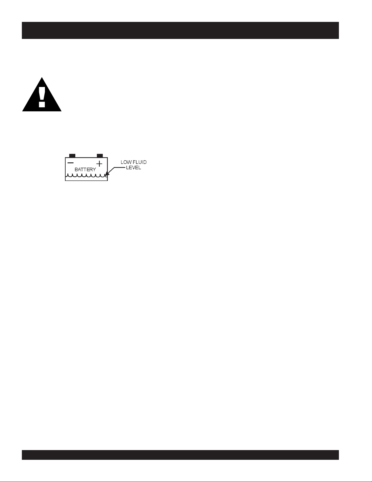
Battery
This unit is of negative ground DO NOT connect in reverse.
Always maintain battery fluid level between the specified
marks. Battery life will be shortened, if the fluid level is not
properly maintained. Add only distilled water when
replenishment is necessary.
Check to see whether the battery cables are loose. Poor
contact may result in poor starting or malfunctions. Always
keep the terminals firmly tightened. Coating the terminals
with a thin film of grease will help inhibit corrosion.
:
Never place hands near the belts or fan while
the generator set is running.
PAGE 46 — DCA-150SSJU — PARTS AND OPERATION MANUAL — REV. #3 (09/07/01)
Page 47

DCA-150SSJU — PRE-SETUP
Battery Cable Installation
ALWAYS be sure the battery cables (Figure 41) are properly
connected to the battery terminals as shown below. The
RED
cable is connected to the positive terminal of the battery,
and the BLACK cable is connected to the negative terminal
of the battery.
Figure 41. Battery Connections
CAUTIONCAUTION
CAUTION
CAUTIONCAUTION
Before connecting battery do the following:
:
If the battery cable is connected
incorrectly, electrical damage to the
generator will occur. Pay close attention
to the polarity of the battery when
connecting the battery.
CAUTIONCAUTION
CAUTION
CAUTIONCAUTION
Wiring
Inspect the entire generator for bad or worn electrical wiring
or connections. If any wiring or connections are exposed
(insulation missing) replace wiring immediately.
Piping and Hose Connection
Inspect all piping, oil hose, and fuel hose connections for
wear and tightness. Tighten all hose clamps and check hoses
for leaks.
If any hose (fuel or oil) lines are defective replace them
immediately.
Ether Canister Operation (During Cold Conditions)
To bleed the ether, crank the engine for at least two
revolutions, then momentarily depress the starting aid button
while the engine is cranking. If the engine does not start,
repeat the cranking process using only short bursts of ether
only while the engine is cranking. Stop injecting the fluid
after then engine starts. If the engine begins to die during
the first few minutes of operation, inject another small shot
of ether.
:
Inadequate battery connections may cause
poor starting of the generator, and create
other malfunctions.
1a. DO NOT connect the battery cables to the battery
terminals when the
the manual or auto position (ON) if the generator is
installed with a microprocessor engine controller.
ALWAYS make sure that the Off/Manual/Auto switch is
in the “OFF” position when connecting the battery.
1b. If the generator is equipped with an ignition switch, make
sure turned to the “OFF” position and the key is removed
from the switch.
2. Place a small amount of grease around both battery
terminals. This will ensure a good connection and will
help prevent corrosion around the battery terminals.
DCA-150SSJU — PARTS AND OPERATION MANUAL — REV. #3 (09/07/01) — PAGE 47
Off/Manual/Auto
switch is in either
CAUTIONCAUTION
CAUTION
CAUTIONCAUTION
WARNINGWARNING
WARNING
WARNINGWARNING
:
Use only ether starting fluid while the
engine is turning or damage may occur.
:
Ether is highly flammable. Do not use
near open fires, flames, or sparks.
Page 48

DCA-150SSJU — LOAD APPLICATION
Single Phase Load
Always be sure to check the nameplate on the generator
CAUTIONCAUTION
CAUTION
CAUTIONCAUTION
and equipment to insure the wattage, amperage and frequency
requirements are satisfactorily supplied by the generator for
operating the equipment.
Generally, the wattage listed on the nameplate of the
equipment is its rated output. Equipment may require 130—
150% more wattage than the rating on the nameplate, as the
wattage is influenced by the efficiency, power factor and
starting system of the equipment.
An inadequate size connecting cable which cannot carry
the required load can cause a voltage drop which can burn
out the appliance or tool and overheat the cable.
When the voltage selector switch is in single phase (240/
z
120V position), place the AC voltmeter change-over switch
to the U-V position and the AC Ammeter change-over switch
to If the generator is equipped with an ignition switch, make
When connecting a resistance load such as an
incandescent lamp or electric heater, a capacity of up
to the generating set’s rated output (kW) can be used.
sure turned to the “OFF” position and the key is removed
z
from the switch to the U or W position to read the output.
When connecting a fluorescent or mercury lamp, a
capacity of up to the generating set’s rated output (kW)
multiplied by 0.6 can be used.
NOTE
If wattage is not given on the
equipment's name plate, approximate
wattage may be determined by
multiplying nameplate voltage by the
z
When connecting an electric drill or other power tools,
pay close attention to the required starting current
capacity.
nameplate amperage.
WATTS = VOLTAGE x AMPERAGE
When connecting ordinary power tools, a capacity of up to
the generating set’s rated output (kW) multiplied by 0.8 can
be used.
:
Motors and motor-driven equipment draw
much greater current for starting than
during operation.
The power factor of this generator is 0.8. See Table 15.
CAUTION:
below when connecting loads.
daoLyBrotcaFrewoP.6elbaT
daoLfOepyTrotcaFrewoP
srotom
noitcudniesahp-elgniS
,sretaehcirtcelE
spmaltnecsednacni
,spmaltnecseroulF
spmalyrucem
,secivedcinortcelE
noitacinummoc
tnempiuqe
slootrewopnommoC8.0
Three Phase Load
When calculating the power requirements for 3-phase power
use the following equation:
PAGE 48 — DCA-150SSJU — PARTS AND OPERATION MANUAL — REV. #3 (09/07/01)
57.0-4.0
0.1
9.0-4.0
0.1
Before connecting this generator to any
building’s electrical system, a licensed
electrician must install an isolation
(transfer) switch. Serious injury or death
may result without this transfer switch.
NOTE
If output (kVA) is not given on the
equipment nameplate, approximate
output may be determined by
multiplying voltage by amperage by
.
Page 49

DCA-150SSJU — GENERATOR START-UP PROCEDURE
NEGATIVE
POSTIVE
BATTERY
WARNING:WARNING:
WARNING:
WARNING:WARNING:
The engine's exhaust contains harmful
emissions.
exhaust when operating inside tunnels,
excavations or buildings. Direct exhaust
away from nearby personnel.
Before Starting
Engine
1. Check the lubricating oil level prior to starting the engine.
Make sure the generator is level. The oil level must be
maintained between two notches on the dipstick.
2. When there is not enough lubricating oil, fill the crankcase
with high grade motor oil. Use a high quality detergent
oil classified CC or higher (See Table 12 on page 45).
3. Check the coolant level in the radiator and subtank.
Replenish with antifreeze as necessary. Always maintain
the coolant level between the FULL and LOW markings
on the coolant container. Be sure that the radiator cap is
fastened securely.
ALWAYS
ventilate the
2. Connect the load to the UVW terminals as shown in
Figure 40. These terminals can be found on the output
terminal panel, (see page 35 Figure 14). To gain access
to the output terminals lift the UVW cover. Tighten
terminal nuts securely to prevent load wires (Figure 43)
from slipping out.
Figure 43. UVW Terminal Lugs (Load)
4. Check the fuel level on the fuel gauge. If fuel is low, fill
the fuel tank diesel fuel. If diesel spillage occurs,
completely wipe up the spilled fuel immediately.
Before Starting
Generator and Control Panel
3. Connect the negative battery cable (BLACK) to the
negative post on the battery (Figure 44).
CAUTION:
z
NEVER start the engine with the
main, GFCI
in the ON position.
1. Be sure to disconnect the electrical load and switch the
main, load
the “OFF” position prior to starting the engine.
and
G.F.C.I.
or
load
circuit breakers
circuit breakers (Figure 42) to
Figure 44. Battery Connections
Figure 42. Main, GFCI and
Load Circuit Breakers
DCA-150SSJU — PARTS AND OPERATION MANUAL — REV. #3 (09/07/01) — PAGE 49
Page 50

DCA-150SSJU — GENERATOR START-UP PROCEDURE (WITH KEY)
4. Close all engine enclosure doors (Figure 45).
Figure 50. Engine Throttle Lever (high)
10. The generator's frequency meter (Figure 51) displays
the 60 cycle output frequency in HERTZ.
Figure 45. Engine Enclosure Doors
5. When starting the generator in COLD weather conditions,
press and hold the engine preheat button (Figure 46).
11. The generator's voltage meter (Figure 52) displays the
120 VAC in VOLTS. If the voltage is not within the
Figure 46. Engine Pre-Heat Button
6. Check the voltage selector switch to desired position.
(Figure 47)
specified frequency tolerance, use the voltage
adjustment control knob (Figure 53) to increase or
decrease the desired voltage.
Figure 51. Frequency Meter (Hz)
Figure 47.Voltage Selector Switch
7. Check the engine throttle lever is in ‘low’ position
(Figure 48).
Figure 48. Engine Throttle Lever (low)
8. Turn the key to ‘Start’ until the engine starts (Figure
49). Then release the key to ‘Run’.
Figure 49. Ignition Switch (Start)
9. Let the engine warm up for a few minutes. Then pull
and turn the throttle lever to the right to set the
engine speed to ‘high’ (Figure 50).
Figure 52. Voltage Meter (Volts)
Figure 53. Voltage Adjust Control Knob
PAGE 50 — DCA-150SSJU — PARTS AND OPERATION MANUAL — REV. #3 (09/07/01)
Page 51

DCA-150SSJU — GENERATOR START-UP PROCEDURE (WITH KEY)
12. The ammeter (Figure 54) will indicate zero amps with no
load applied. When a load is applied, this meter will
indicate the amount of current that the load is drawing
from the generator’s alternator.
40
20
0
60
75
15. The tachometer (Figure 57) will indicate the speed of
the engine when the generator is operating. Under normal
operating conditions this speed is approximately 1800
RPM’s.
A
Figure 54. Ammeter (No Load)
13. The engine oil pressure gauge (Figure 55) will indicate
the oil pressure of the engine. Under normal operating
conditions the oil pressure is approximately 41 to 71
psi.
16. Turn the MAIN, GFCI and LOAD circuit breakers to
their ON position (Figure 58).
Figure 57. Engine Tachometer
Figure 58. Main and GFCI Circuit Breakers
Figure 55. Oil Pressure Gauge
17. Observe the generator's ammeter (Figure 59) and verify
it reads the anticipated amount of current with respect
14. The coolant temperature gauge (Figure 56) will indicate
the coolant temperature. Under normal operating
to the load. The ammeter will only display a current
reading if the load is in use.
conditions the coolant temperature is approximately
215oF.
18. The generator will run until manually stopped or an
abnormal condition occurs.
Figure 56. Coolant Temperature Gauge
40
20
0
60
75
A
Figure 59. Ammeter (Load)
DCA-150SSJU — PARTS AND OPERATION MANUAL — REV. #3 (09/07/01) — PAGE 51
Page 52

DCA-150SSJU — START-UP PROCEDURE (MANUAL-CONTROLLER)
Begin start-up procedure 1-3 on page 49.
4. Close all engine enclosure doors (Figure 60).
Figure 60. Engine Enclosure Doors
5. When starting the generator in COLD weather conditions,
press and hold the engine preheat button (Figure 61).
Figure 61. Engine Pre-Heat Button
9. After engine starts, verify that the "Engine Running"
status LED (Figure 65) on the Engine Controller
display is "ON" (lit). If any faults light, the engine will
shut down. See troubleshooting tables for guidance.
Figure 65. Engine Controller Running Status
LED
10. Let the engine warm up for a few minutes. Change
the idle switch to “HIGH” (Figure 66).
6. Check the voltage selector switch to desired position.
(Figure 61).
Figure 62.Voltage Selector Switch
7. Check the engine throttle switch is in ‘low’ position
(Figure 63).
Figure 63. Engine Switch (LOW)
11. The generator's frequency meter (Figure 67) displays
the 60 cycle output frequency in HERTZ.
8. Place the Off/Manual/Auto switch (Figure 64) in the
MANUAL position. The engine will start cranking.
12. The generator's voltage meter (Figure 68) displays the
120 VAC in VOLTS. If the voltage is not within the
specified frequency tolerance, use the voltage
adjustment control knob (Figure 69) to increase or
decrease the desired voltage.
Figure 64. Off/Manual/Auto Switch (Manual)
Figure 66. Engine Switch (HIGH)
Figure 67. Frequency Meter (Hz)
PAGE 52 — DCA-150SSJU — PARTS AND OPERATION MANUAL — REV. #3 (09/07/01)
Page 53

DCA-150SSJU — START-UP PROCEDURE (MANUAL-CONTROLLER)
Figure 68. Voltage Meter (Volts)
Figure 69. Voltage Adjust Control Knob
13. The ammeter (Figure 70) will indicate zero amps with no
load applied. When a load is applied, this meter will
indicate the amount of current that the load is drawing
from the generator’s alternator.
40
20
0
60
75
16. The tachometer (Figure 73) will indicate the speed of
the engine when the generator is operating. Under normal
operating conditions this speed is approximately 1800
RPM’s.
17. Turn the MAIN, GFCI and LOAD circuit breakers to
their ON position (Figure 74).
Figure 72. Coolant Temperature Gauge
Figure 73. Engine Tachometer
A
Figure 70. Ammeter (No Load)
Figure 74. Main and GFCI Circuit Breakers
14. The engine oil pressure gauge (Figure 71) will indicate
the oil pressure of the engine. Under normal operating
conditions the oil pressure is approximately 41 to 71
psi.
Figure 71. Oil Pressure Gauge
15. The coolant temperature gauge (Figure 72) will indicate
the coolant temperature. Under normal operating
conditions the coolant temperature is approximately
215oF. .
18. Observe the generator's ammeter (Figure 75) and verify
it reads the anticipated amount of current with respect
to the load. The ammeter will only display a current
reading if the load is in use.
19. The generator will run until manually stopped or an
abnormal condition occurs.
40
20
0
60
75
A
Figure 75. Ammeter (Load)
DCA-150SSJU — PARTS AND OPERATION MANUAL — REV. #3 (09/07/01) — PAGE 53
Page 54

DCA-150SSJU — START UP PROCEDURE (AUTO)
With an Engine Controller, starting the generator in the
"AUTO" mode is similar to starting the generator in the
"MANUAL" mode, with a few exceptions.
CAUTION:
CAUTION:
When running the generator in the AUTO
mode, remember the generator can start
up at any time without warning. NEVER
attempt to perform any maintenance when
the generator is in the auto mode.
When starting generator in Auto mode use the "Manual Startup" procedure except where noted (see below).
1. Perform steps 1 through 7 (page 52) as outlined in the
manual starting procedure.
2. Place the Off/Manual/Auto switch (Figure 74) in the
AUTO position .
If the generator is in auto mode, the engine
may crank and attempt to start without
warning. KEEP ALL UNAUTHORIZED
PERSONNEL AWAY.
Figure 74. Off/Manual Auto Switch
(AUTO)
3. Continue to follow the steps outline in the manual startup procedure (start at step 11, page 32).
PAGE 54 — DCA-150SSJU — PARTS AND OPERATION MANUAL — REV. #3 (09/07/01)
Page 55

DCA-150SSJU — SHUTDOWN PROCEDURE
ENGINE SHUTDOWN (Key)
To shutdown the generator, use the following procedure:
1. Switch both the MAIN, GFCI and LOAD circuit breakers
(Figure 75) to the “OFF” position.
Figure 75. Main, GFCI and Load
circuit breakers
2. Set the engine throttle lever to the idle (low) position.
3. Let the engine cool by running it for 3-5 minutes with no
load applied.
4. Turn the starter switch to “STOP” position (Figure 76).
ENGINE SHUTDOWN (Engine Controller)
To shutdown the generator, use the following procedure:
1. Switch both the MAIN, GFCI and LOAD circuit breakers
(Figure 77) to the “OFF” position.
2. Set the engine idle to (low) position.
3. Let the engine cool by running it for 3-5 minutes with no
load applied.
4. Place the Off/Manual/Auto Switch (Figure 78) in the "OFF/
RESET" position.
Figure 77. Main, GFCI and Load
circuit breakers
Figure 76. Starter Switch (Stop
Position)
5. Remove the load from the UVW terminal strip.
DCA-150SSJU — PARTS AND OPERATION MANUAL — REV. #3 (09/07/01) — PAGE 55
Figure 78. Off/Manual Auto Switch (OFF)
5. Verify that the "Engine Running" status LED (Figure 79)
on the Auto/On/Offf Engine Controller display is "OFF"
(not lit).
Figure 79. Engine Controller
Status LED (OFF)
6. Remove the load from the UVW terminal strip.
Page 56

DCA-150SSJU — MAINTENANCE
General Inspection
Prior to each use, the generating set should be cleaned and
inspected for deficiencies. Check for loose, missing or
damaged nuts, bolts or other fasteners. Also check for fuel
or oil leaks.
Engine Side, Fuel, Oil and Coolant (Refer to the Engine
Instruction Manual)
Air Cleaner
Every 50 hours: Remove air cleaner element and clean heavy
duty paper element with kerosene, or foam element with
liquid detergent and hot water. Wrap foam element in a cloth
and squeeze dry. For heavy duty paper element, wipe
excess kerosene with towel. Replace if any damage or unable
to clean.
Fuel Addition
Add diesel fuel (the grade may vary according to season
and locations). Always pour through the mesh filter.
Removing Water from the Tank
After prolonged use, water and other impurities accumulate
in the bottom of the tank. Occasionally remove the drain
cock and drain the contents. During cold weather, the greater
the empty volume inside the tank, the easier it is for water
to condense. This can be reduced by always keeping the
tank as full as possible.
Air Removal
If air enters the fuel injection system of a diesel engine,
starting becomes impossible. After running out of fuel, or
after disassembling the fuel system, bleed the system
according to the following procedure.
To restart after running out of fuel, turn the key switch to the
“START” position for 15-30 seconds. Try again, if needed.
This unit is equipped with an automatic air bleeding system.
Service Daily
If engine is operating in very dusty and dry grass conditions,
a clogged air cleaner will result in high fuel consumption,
loss of power and excessive carbon buildup in the
combustion chamber.
Cleaning the Fuel Strainer
Clean the fuel strainer if it contains dust or water. Remove
dust or water in the strainer cap and wash it in diesel. Securely
fasten the fuel strainer cap so that fuel will not leak. Check
the fuel strainer every 200 hours of operation or once a month.
Check Oil Level/Change Oil
Check the crankcase oil level prior to each use, or when the
fuel tank is filled. Insufficient oil may cause severe damage
to the engine. Make sure the generator is level. The oil level
must be between the two notches on the dipstick as shown
in page 27, Figure 9.
To change the oil, remove oil plug located on the bottom of
the generator. Make sure the to use an oil recycle container
to catch the oil. Replace oil plug. Remove the oil filter
located on the left side of the generator. Remove oil filter
gasket and clean filter mounting pad. Lubricate gasket with
small amount of oil and install new oil filter. Tighten filter
with 1/4 turn after gasket contacts filter housing. DO NOT
overtighten.
Fill with correct oil through oil filler located on the left side of
the generator (see page Table for proper oil and specification
table for proper amount). Crank engine (without starting) for
30 seconds to ensure proper lubrication. Start engine and
check for leaks. Stop engine and check oil level.
Replacing Fuel Filter
Close shut-off valve. Throroughly clean fuel filter assembly
and surrounding area. Loosen drain plug and drain fuel into
a suitable container. Firmly grasp the retaining ring and rotate
it counterclockwise 1/4 turn. Remove ring with filter element.
Inspect filter mounting base for cleanliness. Install new filter
element onto mounting base. Be sure element is properly
indexed and firmly seated on base. It may be necessary to
rotate filter for correct alignment.
Cleaning and Installing Ether Canister
Remove safety cap from ether canister. Remove spray
nozzle from canister. Remove the old canister assembly
from the solenoid and properly dispose the old canister.
Install the new canister and canister assembly to the
solenoid.
CAUTION:
Ether is highly flammable. Do not use near
open fires, flames, or sparks. Do not leave
the canister assembly valve open.
PAGE 56 — DCA-150SSJU — PARTS AND OPERATION MANUAL — REV. #3 (09/07/01)
Page 57

DCA-150SSJU — MAINTENANCE
.61ELBAT
ECNANETNIAM/NOITCEPSNI
sleveLdiulFenignEkcehC X
renaelCriAkcehC X
leveLdicAyrettaBkcehC X
noitidnoCtleBnaFkcehC X
skaeLrofkcehC X
straPfogninesooLrofkcehC X
1
*retliFdnaliOenignEecalpeR
retliFriAnaelC X
ENIGNE
leveLnoitcetorP
knaTleuFfomottoBniarD X
edistuOdnaedisnI,tinUnaelC X
2
*retliFleuFegnahC
retsinaCrehtEecalpeR X
tnalooCkcehCdnarotaidaRnaelC
tnemelEretliFriAecalpeR X
srH01
YLIAD
srH052 srH005 srH0001
X
X
X
rotsiseRnoisorroCegnahC X
spmalCdnasesoHllakcehC X
knaTleuFfoedisnInaelC X
revOecnatsiseRnoitalusnIerusaeM
R
-OTARENEG
smhoM3
1
*
2
*
Generator Storage
For storage of the generator for over 30 days, the following
is required:
z
Drain the fuel tank completely.
z
Completely drain the oil from the crankcase and refill
with fresh oil.
z
Clean all external parts of the generator with a cloth.
z
Cover the generating set and store in a clean, dry place.
X
.ylnoemittsrif,sruoh001taretliffnalioenigneecalpeR
.ylnoemittsrif,sruoH052taretlifleufecalpeR
DCA-150SSJU — PARTS AND OPERATION MANUAL — REV. #3 (09/07/01) — PAGE 57
Page 58

DCA-150SSJU — TROUBLESHOOTING (ENGINE)
Practically all breakdowns can be prevented by proper
handling and maintenance inspections, but in the event of a
breakdown, use the tables shown for
MOTPMYS MELBORPELBISSOP NOITULOS
?dedaolrevO .daolehtnesseL
?metsysleufehtniriA .metsysdeelB
?deggolcepipleuF .epipleufnaelC
?noitcejnileufnevenU .pmupnoitcejniehtecalperroriapeR
?erutarepmet
enatecwolhtiwleuF
?rebmun
esooloteudkaelleuF
diagnosis based on the Engine Troubleshooting (Table 17). If
the problem cannot be remedied, consult our company's
business office or service plant.
?metsysleufehtniretaW .knatleufmorfretawevomeR
ytisocsivhgihylevissecxE
woltalioenigneroleuffo
?tungniniaterepipnoitcejni
)1trap(GNITOOHSELBUORTENIGNE.71ELBAT
.lioenigneroleufdeificepsehtesU
.leufdeificepsehtesU
.tunnethgiT
?gnimitnoitcejnitcerrocnI .tsujdA
pmupnoitcejnI
?gninoitcnuflam
?gniraebrorenil
?nrowtfahsmacleuF .ecalpeR
?deggolcelzzonnoitcejnI .elzzonnoitcejninaelC
,tfahsknarcfoeruzieS
rednilyc,notsip,tfahsmac
morfkaelnoisserpmoC
?gnimitevlavreporpmI .raeggnimitecalperrotcerroC
?nrowrenildnagnirnotsiP .ecalpeR
?ecnaraelcevlavevissecxE .tsujdA
?gniziesstrapenignE .ecalperroriapeR
?gnimitnoitcejnitcerrocnI .gnimittsujdA
?noisserpmoctneicifeD ecnaraelcpottsujdA
nrowrenildnagnirnotsiP
.ecalperroriapeR
.ecalperroriapeR
wolg,tlobdaehrednilycnethgit,teksagdaehecalpeR
.redlohelzzondnagulp
.ecalpeR
,tratstonseodenignE
tsuahxeyargrokcalb
tneicifedro,sag
.tuptuoenigne
?rednilyc
?kcutsro
PAGE 58 — DCA-150SSJU — PARTS AND OPERATION MANUAL — REV. #3 (09/07/01)
Page 59

DCA-150SSJU — TROUBLESHOOTING (ENGINE)
MOTPMYS MELBORPELBISSOP NOITULOS
)2trap(GNITOOHSELBUORTENIGNE.71ELBAT
esooloteudkaelleuF
?tungniniaterepipnoitcejni
pmupnoitcejnI
?gninoitcnuflam
?erusserp
.htooms
.ecruos
tonsinoituloverenignE
?deggolc
?deggolc
?rotorevitcefeD .rotorecalpeR
?ecruosrewop
ondnasesirdeepsenignE
rewopCAnitneserpsiegatlov
gninepoelzzontcerrocnI
rokcutselzzonnoitcejnI
epipwolfrevoleuF
?gninoitcnuflamronrevoG .ecalperroriapeR
?kaelnoisserpmoC
CAnitneserpegatlovoN
?retemtlovevitcefeD .retemtlovecalpeR
?gniriwdetcennocsiD .gniriwriaperdnakcehC
.tunnethgiT
.ecalperroriapeR
.tsujdA
.ecalperroriapeR
.naelC
wolg,tlobdaehrednilycnethgit,teksagdaehecalpeR
.redlohelzzondnagulp
.)1ER(reifitcerecalpeR
nitiucric-trohsreyaL
?gnidniwerutamra
CAdnasesirdeepsenignE
.desuebtonnac
rowolootsiegatlovrewop
.noosootsegrahcsid
yrettabdnasesirdeepsenignE
?gniriwevitcefeD .gniriwriapeR
tubsesirdeepsenignE
.dedaolrevosmeesenigne
?gniraeb
?rekaerbtiucricevitcefeD .rekaerbtiucricecalpeR
?rotalugerenigneevitcefeD .rotalugerecalpeR
?rotanretlaevitcefeD .rotanretlaecalperroriapeR
rotanretlaegamaD
.erutamraecalpeR
.sgniraebrotanretlaecalpeR
DCA-150SSJU — PARTS AND OPERATION MANUAL — REV. #3 (09/07/01) — PAGE 59
Page 60

DCA-150SSJU — TROUBLESHOOTING (ENGINE CONTROLLER)
Practically all breakdowns can be prevented by proper
handling and maintenance inspections, but in the event of a
breakdown, use the tables shown for diagnosis based on
the Engine and Radiator Troubleshooting (Table 18) and Atuo/
On/Off Engine Controller Trouble shooting (if applicable) (Table
19) . If the problem cannot be remedied, consult our
company's business office or service plant.
notpmySesuaCelbissoPnoituloS
?levelliowoL.levelliolliF
erusserpliowoL
.nosithgil
?detrohseriW.eriwriaper/tcepsnI
?leveltnaloocwoL.leveltnalooclliF
leveltnaloocwoL
.nos
ithgil
?rotaidar
?eruliaftinugnidneS.tinugnidnesecalpeR
?egatlovyrettabwoL.yrettabe
alucrictonsiwolfriA
?eruliaftinugnidneserusserpliO .tinugnidneserusserplio
?rellortnocninoitnuflamyaledemiT.relaedotrefeR
?tcerrocninoisnettlebnaF.tlebnafecalper/nethgiT
hguorhtnoit
GNITOOHSELBUORTRELLORTNOCENIGNE.81ELBAT
ecalpeR
grahc/ecalpeR
.llirgrotaidarriaper/naelC
?neposrooD.sroodesolC
tnaloochgiH
sithgilerutrepmet
.no
sithgilknarcrevO
.no
sithgildeepsrevO
.no
etsujda
UPMfossoL
.noro)s(thgil
?gnikaeltsuahxE .trapytluafr
?dedaolrevogniebrotareneG.daolecuder/kcehC
?eruliaftatsomrehT.tatsomrehtecalpeR
?de
kcolbekatniriA.sekatniriallaraelC
?eruliafhctiwserutarepmeT.hctiwserutarepmetecalpeR
?
leuFwolrooN.levelleuflliF
?detarbilacebotsdeenrellortnoC.relaedotrefeR
igneMPR.MPRtsujdA
?d
?hgihootdeepsen
?detsujdaebotsdeenrotautcaronrevoG.rotautcaronrevogtsujdA
ebotsdeenrellortnocronrevoG
?detarbilacebotsdeenrellortnoC.relaedotrefeR
?tne
mtsujdafotuopukcipcitengaM.pukcipcitengamtsujdA
?ytridpukcipcitengaM.pukcipcitengamnaelC
osteksagriaper/ecalpeR
.rellortnocronrevogtsujdA
PAGE 60 — DCA-150SSJU — PARTS AND OPERATION MANUAL — REV. #3 (09/07/01)
Page 61

DCA-150SSJU — WIRING DIAGRAM (GENERATOR)
DCA-150SSJU — PARTS AND OPERATION MANUAL — REV. #3 (09/07/01) — PAGE 61
Page 62

DCA-150SSJU — WIRING DIAGRAM (ENGINE W/ STARTER SWITCH)
PAGE 62 — DCA-150SSJU — PARTS AND OPERATION MANUAL — REV. #3 (09/07/01)
Page 63

DCA-150SSJU — WIRING DIAGRAM (ENGINE WITH CONTROLLER)
DCA-150SSJU — PARTS AND OPERATION MANUAL — REV. #3 (09/07/01) — PAGE 63
Page 64

EXPLANATION OF CODE IN REMARKS COLUMN
How to read the marks and remarks used in this parts
book.
Items Found In the “Remarks” Column
Serial Numbers-Where indicated, this indicates a serial
number range (inclusive) where a particular part is used.
Model Number-Where indicated, this shows that the
corresponding part is utilized only with this specific model
number or model number variant.
Items Found In the “Items Number” Column
All parts with same symbol in the number column, *, #,
+, %, or n, belong to the same assembly or kit.
Note: If more than one of the same reference number is
listed, the last one listed indicates newest (or latest)
part available.
PAGE 64 — DCA-150SSJU — PARTS AND OPERATION MANUAL — REV. #3 (09/07/01)
Page 65

DCA-150SSJU — SUGGESTED SPARE PARTS
DCA-150SSJU W/JOHN DEERE 6081TF001 diesel ENGINE
1 to 5 Units
Qty. P/N Description
10 .............. 0602046379 .....................AIR FILTER
10 .............. 0602042591 .....................FUEL FILTER
10 .............. 0602041291 .....................OIL FILTER
1 ................ 0601808803 .....................CIRCUIT BREAKER
2 ................ 0602011492 .....................ENGINE FAN BELT
1 ................ 0602100056 .....................SWITCH, STARTER
5 ................ AR51481 .......................... KEY SET, STARTER SWITCH (2)
2 ................ 0602122281 .....................OIL SWITCH
1 ................ M3310500203 ..................RADIATOR HOSE (UPPER)
1 ................ M3310500303 ..................RADIATOR HOSE (LOWER)
1 ................ 0605505070 .....................FUEL CAP
1 ................ 0601820671 .....................AUTOMATIC VOLTAGE REGULATOR
1 ................ 0601808815 .....................MAIN CIRCUIT BREAKER
1 ................ 0601808804 .....................CIRCUIT BREAKER
1 ................ 0602103092 .....................PILOT LAMP
2 ................ 0601810245 .....................BULB, PILOT LAMP
1 ................ 0602011068 .....................CAP, RADIATOR
1 ................ 0602122271 .....................UNIT, OIL PRESSURE
1 ................ 0602123261 .....................UNIT, WATER TEMPERATURE
1 ................ 0602121080 .....................CHARGING AMMETER
NOTE
Part number on this Suggested Spare
Parts list may supercede/replace the
P/N shown in the text pages of this
book.
DCA-150SSJU — PARTS AND OPERATION MANUAL — REV. #3 (09/07/01) — PAGE 65
Page 66

GENERATOR ASSY.
DCA-150SSJU — GENERATOR ASSY.
PAGE 66 — DCA-150SSJU — PARTS AND OPERATION MANUAL — REV. #3 (09/07/01)
Page 67

DCA-150SSJU — GENERATOR ASSY.
GENERATOR ASSY.
NO. PART NO. PART NAME QTY. REMARKS
1 C0110000102 ROTOR ASS’Y 1
2 FIELD ASS’Y 1
3 8131070013 FAN 1
4 8131611914 COUPLING DISK 8
5 8131015003 BALANCING PLATE 1
6 0012112035 HEX. HEAD BOLT 10
7 0042612000 LOCK WASHER 10
8 8101026013 SET PLATE RECTIFIER 1
9 0601821349 RECTIFIER .........................................................2 ................ PT 3610
10 0601822601 SERGE ABSORBER .......................................... 1 ................ ERZ- M14JK621A
11 8001020004 INSULATOR WASHER 1
12 8001020504 INSULATOR WASHER 1
13 0010110020 HEX. HEAD BOLT 4
14 0040010000 LOCK WASHER 4
15 0601000209 BALANCING WEIGHT KIT 1
16 0076506312 CERAMIC BEARING ......................................... 1 ................ 6312 SN34 DDU C3
17 C0130000003 STATOR ASS’Y 1
18 0845041804 GROMMET 2
19 8131315202 END BRACKET 1
20 8101350013 FIELD ASS’Y. EXCITER 1
21 0012110060 HEX. HEAD BOLT 4
22 0042610000 LOCK WASHER 4
23 031110160 PLAIN WASHER .................................................4 ................ REPLACES 0041210000
24 0010112035 HEX. HEAD BOLT 6
25 0040012000 LOCK WASHER 6
26 031112230 PLAIN WASHER .................................................6 ................ REPLACES 0041212000
27 8131310104 COVER, BEARING 1
28 8131312204 GASKET BEARING 1
29 8131331003 COVER, END BRACKET 1
30 0105050616 HEX. HEAD BOLT ............................................ 10 ................ REPLACES 0017106012
31 8101333003 COVER, END BRACKET 1
32 0010106030 HEX. HEAD BOLT 2
33 0040006000 LOCK WASHER 2
34 952404470 PLAIN WASHER .................................................2 ................ REPLACES 0041206000
35 M3163400303 COUPLING RING 1
36 0013904064 HEX. HEAD BOLT ............................................... 8 ................ S/N 7600001 TO 7600036
0343204230 HEX. HEAD BOLT ............................................... 8 ................ S/N7600037~
37 EM923344 LOCK WASHER .................................................. 8 ................REPLACES 0043604000
38 0070506306 BEARING ............................................................ 1 ................ 6306ZZ
39 0012810030 HEX. HEAD BOLT 12
40 0013904032 HEX. HEAD BOLT ............................................ 12 ................ S/N7600001 TO 7600036
0343204120 HEX. HEAD BOLT ............................................ 12 ................ S/N7600037~
41 EM923344 LOCK WASHER ............................................... 12 ................ REPLACES 0043604000
42 C0131300004 COVER, FAN 1
43 0605000013 RUBBER SUSPENSION 2
44 0030016000 HEX. NUT 2
0040016000 LOCK WASHER 2
45 020106050 NUT .....................................................................1 ................ REPLACES 0600815000
DCA-150SSJU — PARTS AND OPERATION MANUAL — REV. #3 (09/07/01) — PAGE 67
Page 68

CONTROL BOX ASSY.
DCA-150SSJU —CONTROL BOX ASSY.
PAGE 68 — DCA-150SSJU — PARTS AND OPERATION MANUAL — REV. #3 (09/07/01)
Page 69

DCA-150SSJU — CONTROL BOX ASSY.
CONTROL BOX ASSY.
NO. PART NO. PART NAME QTY. REMARKS
M3246700814 WIRE HARNESS, GENERATOR 1
1 M3213000302 CONTROL BOX ............................................. 1 ......... S/N7600001 TO 7600036
M3213000312 CONTROL BOX ............................................. 1 ......... S/N7600037 TO 7600090
M3213000322 CONTROL BOX ............................................. 1 ......... S/N7600091~
2 0601808815 CIRCUIT BREAKER ....................................... 1 .........LAF364001021 3P 400A
3 0021006080 MACHINE SCREW 4
4 0601823863 RELAY UNIT ................................................... 2 .........MSA9013A
5 0021304015 MACHINE SCREW ......................................... 4 .........REPLACES 0027104015
6 0601820671 AUTOMATIC VOLTAGE REGULATOR ......... 1 ......... NTA- 5A- 2DB
7 0027105010 MACHINE SCREW ......................................... 4 .........S/N7600001 TO 7600036
0027105015 MACHINE SCREW ......................................... 4 .........S/N7600037~
8 0601806127 CURRENT TRANSFORMER ........................ 3 .........814- 943 300/5A
9 011808015 MACHINE SCREW ......................................... 6 .........REPLACES 0027106015
10 0601820845 OVER CURRENT RELAY .............................. 1 ......... LR2D1308
11 0601820846 OVER CURRENT RELAY .............................. 1 ......... LA7D1064
12 M1260600004 FITTING BRACKET ....................................... 1 .........S/N7600001 TO 7600036
13 0021304015 MACHINE SCREW ......................................... 2 .........REPLACES 0027104015
0207004000 HEX. NUT 2
14 0027104010 MACHINE SCREW ......................................... 2 .........S/N7600001 TO 7600036
15 M3213500013 CONTROL BOX COVER ............................... 1 ......... S/N7600001 TO 7600036
M3213500013 CONTROL BOX COVER .............................. 1 .........S/N7600014~
16 011106015 HEX. HEAD BOLT .......................................... 4 ......... REPLACES 0016906015
17 M3923100014 SELECTOR SWITCH .................................... 1 ......... VY- 200
18 M3213600203 SWITCH BRACKET 1
19 0330000370 EDGES ........................................................... 2 .........REPLACES 0330000370
20 0027104010 MACHINE SCREW 4
21 011106015 HEX. HEAD BOLT .......................................... 8 ......... REPLACES 0016906015
22 M3213600304 SWITCH COVER 1
23 011106015 HEX. HEAD BOLT .......................................... 4 ......... REPLACES 0016906015
24 0016906015 HEX. HEAD BOLT 13
0040506000 TOOTHED WASHER 1
25 M3223000303 CONTROL PANEL 1
26 0601807630 FREQUENCY METER ................................... 1 ......... 264250DJDJ9
27 0601808954 AC AMMETER ................................................ 1 ......... 260240LSLS1JBZ
28 0601801040 CHANGE - OVER SWITCH, AMMETER ...... 1 ......... SL - 2AS
29 0601806814 AC VOLTMETER ............................................ 1 ......... 264230SJSJ9
30 0601801041 CHANGE - OVER SWITCH, VOLTMETER .. 1 .........SL - 2VS
31 0601840073 RHEOSTAT ( VOLTAGE REGULATOR) ....... 1 .........RA20A2SE102BJ
32 0601840121 KNOB 1
33 M1223100004 STOPPER 1
34 0027105015 MACHINE SCREW ......................................... 2 .........S/N7600001 TO 7600036
0027105010 MACHINE SCREW ......................................... 2 .........S/N7600037~
35 0027105015 MACHINE SCREW ......................................... 4 .........S/N7600001 TO 7600036
0027105010 MACHINE SCREW ......................................... 4 .........S/N7600037~
DCA-150SSJU — PARTS AND OPERATION MANUAL — REV. #3 (09/07/01) — PAGE 69
Page 70

CONTROL BOX ASSY.
DCA-150SSJU —CONTROL BOX ASSY.
PAGE 70 — DCA-150SSJU — PARTS AND OPERATION MANUAL — REV. #3 (09/07/01)
Page 71

DCA-150SSJU —CONTROL BOX ASSY.
CONTROL BOX ASSY.
NO. PART NO. PART NAME QTY. REMARKS
36 M9220100004 SET SCREW 1
37 0080200007 SNAP RING 1
38 0601821370 RECTIFIER..................................................... 1 ......... REPLACES 0601823240;
DE 4503
39 0027104020 MACHINE SCREW 1
40 0602200478 EMERGENCY RELAY .................................... 1 .........S/N7600001 TO 7600090;1070160603
41 0027105040 MACHINE SCREW ......................................... 2 .........S/N7600001 TO 7600090
42 0602202592 STARTER RELAY .......................................... 1 ......... AT141011
43 011808015 MACHINE SCREW......................................... 2 .........REPLACES 0027106015
44 0602202597 RELAY ............................................................ 1 .........AL81719
45 0027105015 MACHINE SCREW 1
46 0601823240 RECTIFER ..................................................... 1 ......... S/N7600091~; DE4503
47 DYN110754000012 CONTROLLER .............................................. 1 .........S/N7600091~; REPLACES 0602202546
48 0027105015 MACHINE SCREW ......................................... 1 .........S/N7600091~
49 LY2D12VD RELAY ............................................................ 1 .........S/N7600091~; REPLACES 0601827656
0601823109 BASE .............................................................. 1 ......... S/N7600091~; PTF08AE
PYCA1 CLIP ................................................................ 2 ......... S/N7600091~; REPLACES 0601824400
50 0027104020 MACHINE SCREW ......................................... 2 .........S/N7600091~
51 0601840240 POTENIOMETER .......................................... 1 .........S/N7600091~; 73JB5000 2W 5k
DCA-150SSJU — PARTS AND OPERATION MANUAL — REV. #3 (09/07/01) — PAGE 71
Page 72

ENGINE & RADIATOR ASSY.
CONTROL BOX ASSY.
DCA-150SSJU —ENGINE AND RADIATOR ASSY.
S/N7600091~
PAGE 72 — DCA-150SSJU — PARTS AND OPERATION MANUAL — REV. #3 (09/07/01)
Page 73

DCA-150SSJU —ENGINE AND RADIATOR ASSY.
ENGINE & RADIATOR ASSY.
NO. PART NO. PART NAME QTY. REMARKS
1 M3923200024 ENGINE .................................. 1 ......... JOHN DEERE 6081TF;
S/N7600001 to 7600108
M3925200024 ENGINE .................................. 1 ......... JOHN DEERE 6081TF; S/N7600109~
0602011492 FAN BELT ............................... 1 ......... 2402
2 0602041291 ELEMENT, OIL FILTER .......... 1 ......... RE57394
3 0602042591 ELEMENT, FUEL FILTER ....... 1 ......... AR86745
4 0602060012 BLOWER FAN ........................ 1 ......... REPLACES 0602060002;
RE20967
5 0602061001 FAN SPACER ......................... 1 ......... S/N7600001 TO 7600120;R128767
0602061002 FAN SPACER ......................... 1 ......... S/N7600121~;R100676
6 0013904178 HEX HEAD BOLT ................... 6 ......... S/N7600001 TO 7600120
0343304350 HEX. HEAD BOLT .................. 6 ......... S/N7600121~
7 0043004000 LOCK WASHER 6
8 M3303200003 ENGINE FOOT 2
9 0013907076 HEX HEAD BOLT 8
10 0043007000 LOCK WASHER 8
11 0605000011 RUBBER SUSPENSION 2
12 0030016000 HEX NUT 2
13 0040016000 LOCK WASHER 2
14 0602012720 RADIATOR .............................. 1 ......... S/N7600001 TO 7600120;RE65161
0602012724 RADIATOR .............................. 1 ......... S/N7600121~; C2810060002
15 0602011068 CAP ........................................ 1 ......... S/N7600001 TO 7600120
0602011066 CAP ........................................ 1 ......... S/N7600121~; C89C0225010
16 0602010691 SHROUD ................................ 1 ......... S/N7600001 TO 7600120;R132912
0602010692 SHROUD ................................ 1 ......... S/N7600121~; C2810064100
17 0602010795 FAN COVER ........................... 1 ......... S/N7600001 TO 7600120;C2810044210
0602010796 FAN COVER ........................... 1 ......... S/N7600121~;C2810064200
18 012210025 HEX HEAD BOLT ................... 8 ......... REPLACES 0016910025;
S/N7600001 TO 7600120
0343003070 HEX. HEAD BOLT .................. 5 ......... S/N7600121~
0043003000 LOCK WASHER ...................... 5 ......... S/N7600121~
0043103000 PLAIN WASHER ..................... 5 ......... S/N7600121~
19 M3310200604 RADIATOR BRACKET ............ 1 ......... S/N7600001 TO 7600120
20 M3310200504 RADIATOR BRACKET ............ 1 ......... S/N7600001 TO 7600120
21 0013003019 HEX HEAD BOLT ................... 8 ......... S/N7600001 TO 7600120
22 0043003000 LOCK WASHER ...................... 8 ......... S/N7600001 TO 7600120
23 0043103000 PLAIN WASHER ..................... 8 ......... S/N7600001 TO 7600120
24 011008020 HEX HEAD BOLT ................... 8 ......... REPLACES 0016908020
25 M3310500203 RADIATOR HOSE ................... 1 ......... S/N7600001 TO 7600120
M3310500603 RADIATOR HOSE ................... 1 ......... S/N7600121~
26 M3310500303 RADIATOR HOSE ................... 1 ......... S/N7600001 TO 7600120
M3310500706 RADIATOR HOSE ................... 1 ......... S/N7600121~
DCA-150SSJU — PARTS AND OPERATION MANUAL — REV. #3 (09/07/01) — PAGE 73
Page 74

ENGINE & RADIATOR ASSY.
DCA-150SSJU —ENGINE AND RADIATOR ASSY.
S/N7600091~
PAGE 74 — DCA-150SSJU — PARTS AND OPERATION MANUAL — REV. #3 (09/07/01)
Page 75

DCA-150SSJU —ENGINE AND RADIATOR ASSY.
ENGINE & RADIATOR ASSY.
NO. PART NO. PART NAME QTY. REMARKS
27 0605515148 HOSE BAND .......................... 3 ......... S/N7600001 TO 7600120
0605515148 HOSE BAND .......................... 1 ......... S/N7600121~
28 0605515147 HOSE BAND .......................... 1 ......... S/N7600001 TO 7600120
0605515147 HOSE BAND .......................... 3 ......... S/N7600121~
29 0605512194 HOSE JOINT .......................... 1 ......... S/N7600001 TO 7600120
30 7812014003B DRAIN JOINT ......................... 1 ......... S/N7600001 TO 7600120;
REPLACES M2320300103
31 M9200200004 DRAIN BOLT .......................... 1 ......... S/N7600001 TO 7600120
32 0150000018 O RING ................................... 1 ......... S/N7600001 TO 7600120
33 011206020 HEX HEAD BOLT ................... 2 ......... S/N7600001 TO 7600120;
REPLACES 0016906020
34 0191300730 DRAIN HOSE ......................... 1 ......... S/N7600001 TO 7600120
35 0605515189 HOSE BAND .......................... 2 ......... S/N7600001 TO 7600120
36 0602046255 AIR CLEANER ........................ 1 ......... S/N7600001 TO 7600141;FWG120063
0602046583 AIR CLEANER ........................ 1 ......... S/N7600142~; FRG110206
0602046379 ELEMENT, AIR CLEANER ..... 1 ......... S/N7600001 TO 7600141; XLP18- 2035
0602046680 ELEMENT, AIR CLEANER ..... 1 ......... S/N7600142~; P532966
37 0602040650 INDICATOR, AIR CLEANER ... 1 ......... RBX002252
38 0602040591 BAND, AIR CLEANER ............ 2 ......... S/N7600001 TO 7600141
0602040555 BAND, AIR CLEANER ............ 2 ......... S/N7600142~; P004079
39 011008020 HEX HEAD BOLT ................... 4 ......... REPLACES 0016908020
40 020108060 HEX NUT ................................ 4 ......... REPLACES 0207008000
41 M3373100103 HOSE , AIR CLEANER .......... 1 ......... S/N7600001 TO 7600141
M3373100113 HOSE, AIR CLEANER ........... 1 ......... S/N7600142~
42 0605515200 HOSE BAND .......................... 2 ......... S/N7600001 TO 7600141
0605515200 HOSE BAND .......................... 1 ......... S/N7600142~
43 0602022564 ADAPTER 1
44 0602021165 O RING 1
45 0602022562 UNION .................................... 1 ......... S/N7600001 TO 7600090
46 0602022792 SWIVEL 1
47 0602021070 CAP 1
48 0602021572 DRAIN HOSE ......................... 1 ......... S/N7600001 TO 7600090
0269200390 DRAIN HOSE ......................... 1 ......... S/N760091~; 83610 L=390
49 M9300000203 RESERVE TANK 1
50 0802010900 CAP, RESERVE TANK ............ 1 ......... REPLACES 0602010900
51 M3316100104 BRACKET, RESERVE TANK 1
52 011008020
53 0193601200 HOSE 1
54 M3313100104 RADIATOR COVER ................. 1 ......... S/N7600001 TO 7600120
HEX HEAD BOLT ................... 2 ......... REPLACES 0016908020
DCA-150SSJU — PARTS AND OPERATION MANUAL — REV. #3 (09/07/01) — PAGE 75
Page 76

ENGINE & RADIATOR ASSY.
DCA-150SSJU —ENGINE AND RADIATOR ASSY.
S/N7600091~
PAGE 76 — DCA-150SSJU — PARTS AND OPERATION MANUAL — REV. #3 (09/07/01)
Page 77

DCA-150SSJU —ENGINE AND RADIATOR ASSY.
ENGINE & RADIATOR ASSY.
NO. PART NO. PART NAME QTY. REMARKS
M3313100304 RADIATOR COVER................. 1 ......... S/N7600121~
M3493600004 ACOUSTIC SHEET ................ 1 ......... S/N7600001 TO 7600120
M3493600014 ACOUSTIC SHEET ................ 1 ......... S/N7600121~
55 011008020 HEX HEAD BOLT ................... 4 ......... REPLACES 0016908020
56 M3483400104 ALTERNATOR COVER 1
57 011008020 HEX HEAD BOLT 3 ......... REPLACES 0016908020
58 0602220911 CLAMP 1
59 011008020 HEX HEAD BOLT ................... 1 ......... REPLACES 0016908020
60 0602122281 OIL SWITCH ........................... 1 ......... 17189- 39011
61 M9200100704 ADAPTER 1
62 0602123282 WATER SWITCH .................... 1 ......... 15181- 83041
63 M9200100404 ADAPTER 1
64 0602014298 ETHER KIT ............................. 1 ......... AR68492
65 011106015 HEX HEAD BOLT ................... 2 ......... REPLACES 0016906015
66 0041216000 PLAIN WASHER ..................... 8 ......... S/N7600001 TO 7600120
67 M3326200004 HOSE BRACKET ................... 1 ......... S/N7600001 TO 7600090
68 0013003019 HEX HEAD BOLT ................... 1 ......... S/N7600001 TO 7600090
69 0043003000 LOCK WASHER ...................... 1 ......... S/N7600001 TO 7600090
70 0043103000 PLAIN WASHER ..................... 1 ......... S/N7600001 TO 7600090
71 0605511395 VALVE .................................... 1 ......... S/N7600091~; XV500P8
72 DYNC10502000012 ACTUATOR ............................. 1 ......... S/N7600091~; REPLACES 0602150095
73 M3356200203 STOPPER BRACKET ................ 1 ........... S/N7600091~
74 0016906020 HEX. HEAD BOLT ...................... 2 ........... S/N7600091~
75 M3356200103 ACTUATOR BRACKET ............. 1 ........... S/N7600091~
76 0343502009 CAP SCREW .............................. 4 ........... S/N7600091~
0036302000 HEX. HEAD NUT ........................ 4 ........... S/N7600091~
0043002000 LOCK WASHER ......................... 4 ........... S/N7600091~
0343003008 HEX. HEAD BOLT ...................... 2 ........... S/N7600091~
0043003000 LOCK WASHER ......................... 2 ........... S/N7600091~
77 0602180090 CLEVIS ....................................... 1 ........... S/N7600091~
78 0602180290 ROD END ................................... 2 ........... S/N7600091~
79 0343002010 HEX. HEAD BOLT ...................... 2 ........... S/N7600091~
0036302000 HEX. HEAD BOLT ...................... 2 ........... S/N7600091~
0043002000 LOCK WASHER ......................... 2 ........... S/N7600091~
80 M3356100004 THROTTLE LEVER ................... 1 ........... S/N7600091~
81 0603306590 CONNECTOR............................ 1 ........... S/N7600091~;10WFTXS
82 0603300285 ROCK NUT ................................ 1 ........... S/N7600091~; 10WLN
83 0603306395 HOSE JOINT .............................. 1 ...........
84 0036302000 HEX. HEAD NUT ........................ 2 ...........
85 M3356300004 THROTTLE THREAD ................ 1 ........... S/N7600091~
86 0605515231 HOSE BAND .............................. 1 ........... S/N7600142~; 5080
S/N7600091~; 30182810
S/N7600091~
DCA-150SSJU — PARTS AND OPERATION MANUAL — REV. #3 (09/07/01) — PAGE 77
Page 78

DCA-150SSJU —ENGINE OPERATING PANEL ASSY.
ENGINE OPERATING PANEL ASSY.
S/N 7600001 TO S/N7600090
S/N 7600091~
PAGE 78 — DCA-150SSJU — PARTS AND OPERATION MANUAL — REV. #3 (09/07/01)
Page 79

DCA-150SSJU —ENGINE OPERATING PANEL ASSY.
ENGINE OPERATING PANEL ASSY.
NO. PART NO. PART NAME QTY. REMARKS
M3357200112 WIRE HARNESS, ENGINE ......................... 1 .............S/N7600001 TO 7600090
M3357200122 WIRE HARNESS, ENGINE ......................... 1 .............S/N7600091 TO 7660108
M3357200132 WIRE HARNESS, ENGINE ......................... 1 .............S/N7600109~
1 M1354300304 SLIDE LEVER ............................................. 1 ............. S/N7600001 TO 7600090
2 0601840190 KNOB .......................................................... 1 .............S/N7600001 TO 7600090;
REPLACES M9320000004
3 020108060 HEX NUT ..................................................... 1 ............. S/N7600001 TO 7600090;
REPLACES 0036003000
4 M1354200004 BRACKET ................................................... 1 ............. S/N7600001 TO 7600090
5 020108060 HEX NUT ..................................................... 1 ............. S/N7600001 TO 7600090;
REPLACES 0207008000
6 020108060 HEX NUT ..................................................... 1 ............. S/N7600001 TO 7600090;
REPLACES 0030008000
7 0605010550 SNAP PIN ................................................... 1 ............. S/N7600001 TO 7600090
8 M3354600004 GOVERNOR LEVER ................................... 1 .............S/N7600001 TO 7600090
9 M3354600104 GOVERNOR BOLT ...................................... 1 ............. S/N7600001 TO 7600090
10 0036203000 HEX NUT ..................................................... 1 .............S/N7600001 TO 7600090
11 M3354300204 GOVERNOR ROD ....................................... 1 ............. S/N7600001 TO 7600090
12 M3354300304 GOVERNOR ROD ....................................... 1 ............. S/N7600001 TO 7600090
13 020108060 HEX NUT ..................................................... 2 ............. S/N7600001 TO 7600090;
REPLACES 0030008000
14 0602180106 BALL JOINT ................................................ 2 ............. S/N7600001 TO 7600090
15 020108060 HEX NUT ..................................................... 2 ............. S/N7600001 TO 7600090;
REPLACES 0030008000
16 0602180107 BALL JOINT ................................................ 2 ............. S/N7600001 TO 7600090
17 020108060 HEX NUT ..................................................... 2 ............. S/N7600001 TO 7600090;
REPLACES 0036508000
18 0207006000 HEX NUT ..................................................... 4 .............S/N7600001 TO 7600090
952404470 PLAIN WASHER .......................................... 4 ............. S/N7600001 TO 7600090;
REPLACES 0041206000
19 0602100056 STARTER SWITCH ..................................... 1 ............. S/N7600001 TO 7600090; AR58126
0602100028 SET NUT ..................................................... 1 .............S/N7600001 TO 7600090; R44342
0602100029 SET WASHER ............................................. 1 ............. S/N7600001 TO 7600090; A4827R
20 0601831594 COLD STARTING BUTTON ......................... 1 .............S/N7600001 TO 7600036; R39554
0601831585 COLD STARTING BUTTON ......................... 1 ............. S/N7600037~; 44047
0601831584 CAP ............................................................. 1 .............T55585; S/N7600001 TO 7600036
0601831588 CAP
21 0602120096 TACHOMETER ............................................ 1 .............103678
............................................................. 1 ............. S/N7600037~; 44053
DCA-150SSJU — PARTS AND OPERATION MANUAL — REV. #3 (09/07/01) — PAGE 79
Page 80

ENGINE OPERATING PANEL ASSY.
DCA-150SSJU —ENGINE OPERATING PANEL ASSY.
S/N 7600001 TO S/N7600090
S/N 7600091~
PAGE 80 — DCA-150SSJU — PARTS AND OPERATION MANUAL — REV. #3 (09/07/01)
Page 81

DCA-150SSJU —ENGINE OPERATING PANEL ASSY.
ENGINE OPERATING PANEL ASSY.
NO. PART NO. PART NAME QTY. REMARKS
22 0602122093 OIL PRESSURE GAUGE ............................ 1 ............. 100174
23 0602122272 UNIT, OIL PRESSURE ................................ 1 ............. S/N7600001 TO 7600036;105965;
REPLACES 0602122271
0602122272 UNIT, OIL PRESSURE; ............................... 1 .............S/N7600037~;108497
24 0602123092 WATER TEMPERATURE GAUGE ............... 1 ............. 100182
25 0602123261 UNIT, WATER TEMPERATURE; ................... 1 ............. 0202500
26 0602121080 CHARGING AMMETER .............................. 1 ............. 100158
27 0602125090 FUEL GAUGE.............................................. 1 ............. 100176
28 0602103092 ALARM LAMP ............................................. 2 ............. S/N7600001 TO 7600090; PL- 05
0601810245 BULB ........................................................... 2 .............S/N7600001 TO 7600090;
E- 10 T- 10 DC18V
29 0601810141 PANEL LIGHT .............................................. 1 ............. 98268- 00370
30 0601831330 SWITCH, PANEL LIGHT.............................. 1 ............. 90- 0001
31 ECU9988N ENGINE CONTROLLER .............................. 1 ............. S/N 7600091~
REPLACES 0602202546
32 0601831340 SWITCH ...................................................... 1 .............S/N760091~;7562K4
33 0601831395 SWITCH ...................................................... 1 .............S/N7600091~; 7602K36
34 0027104035 MACHINE SCREW ...................................... 2 ............. S/N7600091~
0207004000 HEX. NUT .................................................... 2 ............. S/N7600091~
DCA-150SSJU — PARTS AND OPERATION MANUAL — REV. #3 (09/07/01) — PAGE 81
Page 82

OUTPUT TERMINAL ASSY.
DCA-150SSJU —OUTPUT TERMINAL ASSY.
ADD THE FOLLOWING DIGITS AFTER THE PART NUMBER
WHEN ORDERING ANY PAINTED PANEL TO INDICATE
COLOR OF UNIT:
1-ORANGE
2-WHITE
3 -SPECTRUM GRAY
4 -SUNBELT GREEN
THE SERIAL NUMBER MAY BE REQUIRED.
5 -BLACK
6 -CATERPILLAR YELLOW
7 -CATO GOLD
8 -RED
PAGE 82 — DCA-150SSJU — PARTS AND OPERATION MANUAL — REV. #3 (09/07/01)
Page 83

DCA-150SSJU —OUTPUT TERMINAL ASSY.
OUTPUT TERMINAL ASSY.
NO. PART NO. PART NAME QTY. REMARKS
1 M3230700003 TERMINAL PANEL 1
2 M9220100304 OUTPUT TERMINAL BOLT 5
3 0801830804 TIE BOLT ........................................................ 5 .......... REPLACES M9220100404
4 0039316000 HEX NUT 10
5 0040016000 LOCK WASHER 15
6 0041416000 PLAIN WASHER 20
7 0012108035 HEX HEAD BOLT ............................................ 5 .......... REPLACES 0016908035
8 M3236100303 TERMINAL COVER ......................................... 1 .......... S/N 7600001 TO 7600090
M3238100103 TERMINAL COVER ......................................... 1 .......... S/N7600091~
9 M3236100104 OUTPUT WINDOW 1
10 0605010040 HINGE 2
11 0027103010 MACHINE SCREW 4
0207003000 HEX NUT ......................................................... 4 ..........REPLACES 0030003000
58413 PLAIN WASHER .............................................. 4 ..........REPLACES 0041203000
12 0027103010 MACHINE SCREW 4
0207003000 HEX NUT ......................................................... 4 ..........REPLACES 0030003000
13 0112206020 HEX HEAD BOLT ............................................ 2 ..........REPLACES 0016906020
14 011106015 HEX HEAD BOLT ............................................ 4 ..........REPLACES 0016906015
15 M3236400004 CABLE OUTLET COVER 1
16 M3236300004 SUPPORTER, CABLE OUTLET COVER 1
17 011206020 HEX HEAD BOLT ............................................ 6 ..........REPLACES 0016906020
18 0601808803 CIRCUIT BREAKER ........................................ 2 .......... QOU 120B 1P 20A
19 0601808804 CIRCUIT BREAKER ........................................ 3 .......... QOU 250B 2P 50A
20 M1260700304 BREAKER FITTING COVER 1
21 0222100150 CUSHION RUBBER 1
22 011206020 HEX HEAD BOLT ............................................ 2 ..........REPLACES 0016906020
23 0601812597 RECEPTACLE ................................................. 2 ..........REPLACES 0601812598;
GF530EM 125V 20A X 2
24 0601811034 RECEPTACLE ................................................. 3 ..........REPLACES 0601812538;
CS6369 250V 50A
25 0021304015 MACHINE SCREW ........................................ 10 .......... REPLACES 0027104015
0030004000 HEX NUT ....................................................... 10 ..........REPLACES 0207004000
26 M3236100213 TERMINAL COVER 1
27 012212045 HEX HEAD BOLT ............................................ 2 ..........REPLACES 0010112045
28 031112230 PLAIN WASHER .............................................. 2 ..........REPLACES 0041212000
29 M9310200004 STAY RUBBER 2
30 0030012000 HEX NUT 2
31 0603306775 PLUG ............................................................... 2 ..........S/N7600091~
32 0027104015 MACHINE SCREW .......................................... 4 .......... S/N7600091~
33 0601815194 TERMINAL ...................................................... 1 .......... S/N7600091~; 601GP02
34 0027104015 MACHINE SCREW .......................................... 2 .......... S/N7600091~
DCA-150SSJU — PARTS AND OPERATION MANUAL — REV. #3 (09/07/01) — PAGE 83
Page 84

BATTERY ASSY.
DCA-150SSJU —BATTERY ASSY.
PAGE 84 — DCA-150SSJU — PARTS AND OPERATION MANUAL — REV. #3 (09/07/01)
Page 85

DCA-150SSJU —BATTERY ASSY.
BATTERY ASSY.
NO. PART NO. PART NAME QTY. REMARKS
1 0602220196 BATTERY ........................................................ 1 .......... 4D- 2
2 M9310500404 BATTERY SHEET 1
3 M9103000504 BATTERY BAND 1
4 0602220921 BATTERY BOLT SET 2
5 0040006000 LOCK WASHER 2
6 M3346900204 BATTERY CABLE ............................................ 1 .......... S/N7600001 TO 7600003
M3346900214 BATTERY CABLE ............................................ 1 .......... S/N7600004
M3346900214 BATTERY CABLE 1
7 M3346900104 BATTERY CABLE ............................................ 1 .......... REPLACES M3346900304
8 CABLE 1
9 0013007025 HEX HEAD BOLT 1
0043007000 LOCK WASHER 1
0043107000 PLAIN WASHER 1
0040516000 TOOTHED WASHER 1
10 012210020 HEX HEAD BOLT ............................................ 1 ..........REPLACES 0017110020
0040510000 TOOTHED WASHER 1
DCA-150SSJU — PARTS AND OPERATION MANUAL — REV. #3 (09/07/01) — PAGE 85
Page 86

MUFFLER ASSY.
DCA-150SSJU —MUFFLER ASSY.
PAGE 86 — DCA-150SSJU — PARTS AND OPERATION MANUAL — REV. #3 (09/07/01)
Page 87

DCA-150SSJU —MUFFLER ASSY.
MUFFLER ASSY.
NO. PART NO. PART NAME QTY. REMARKS
1 M3330100202 MUFFLER ........................................................ 1 .......... S/N7600001 TO 7600030
0602300168 MUFFLER ........................................................ 1 ..........S/N7600031~
2 012210025 HEX HEAD BOLT ............................................ 4 .......... REPLACES 0016910025
3 M3333000503 EXHAUST PIPE 1
4 0602325066 CLAMP 1
5 M3333200104 GASKET 1
6 0017110050 HEX HEAD BOLT 4
7 M3330400804 COVER 1
8 M3330400903 BRACKET 1
9 011008020 HEX HEAD BOLT ............................................ 4 .......... REPLACES 0016908020
10 0602326062 U BOLT SET 1
DCA-150SSJU — PARTS AND OPERATION MANUAL — REV. #3 (09/07/01) — PAGE 87
Page 88

FUEL TANK ASSY.
DCA-150SSJU —FUEL TANK ASSY.
PAGE 88 — DCA-150SSJU — PARTS AND OPERATION MANUAL — REV. #3 (09/07/01)
Page 89

DCA-150SSJU —FUEL TANK ASSY.
FUEL TANK ASSY.
NO. PART NO. PART NAME QTY. REMARKS
1 M3363000402 FUEL TANK 1
1-1 0605505070 CAP, FUEL TANK 1
2 M3363200204 TANK BAND 2
3 M9310500104 SUPPORTER SHEET 4
4 011008020 HEX HEAD BOLT ............................................ 2 .......... REPLACES 0016908020
5 0207308000 HEX NUT 2
6 0222100660 RUBBER SHEET 2
7 1502025103C DRAIN JOINT .................................................. 1 .......... REPLACES M9200000003
8 M9200200004 DRAIN BOLT 1
9 0150000018 O RING 1
10 011206020 HEX HEAD BOLT ............................................ 2 ..........REPLACES 0016906020
11 M1363400104 DRAIN HOSE 1
12 0605515198 HOSE BAND 2
13 0602042420 FUEL FILTER .................................................. 1 ..........PTG15P
14 0605512195 HOSE JOINT ................................................... 1 .......... S/N760001 TO 7600036
14 0602022793 HOSE JOINT ................................................... 1 .......... S/N7600037~
15 0602042601 LEAK - OFF LINE ............................................ 1 ..........67050
16 0191300100 SUCTION HOSE 1
17 0191300900 SUCTION HOSE 1
18 0191302400 RETURN HOSE 1
19 0605515109 HOSE BAND 6
DCA-150SSJU — PARTS AND OPERATION MANUAL — REV. #3 (09/07/01) — PAGE 89
Page 90

ENCLOSURE ASSY.
DCA-150SSJU —ENCLOSURE ASSY.
ADD THE FOLLOWING DIGITS AFTER THE PART NUMBER
WHEN ORDERING ANY PAINTED PANEL TO INDICATE
COLOR OF UNIT:
1-ORANGE
2-WHITE
3 -SPECTRUM GRAY
4 -SUNBELT GREEN
THE SERIAL NUMBER MAY BE REQUIRED.
5 -BLACK
6 -CATERPILLAR YELLOW
7 -CATO GOLD
8 -RED
PAGE 90 — DCA-150SSJU — PARTS AND OPERATION MANUAL — REV. #3 (09/07/01)
Page 91

DCA-150SSJU —ENCLOSURE ASSY.
ENCLOSURE ASSY.
NO. PART NO. PART NAME QTY. REMARKS
1 M3413000402 BASE .............................................................. 1 .......... S/N7600001 TO 7600120
M3413000412 BASE .............................................................. 1 .......... S/N7600121~
2 M1413400004 UNDER COVER 1
3 011008020 HEX HEAD BOLT ............................................ 2 .......... REPLACES 0016908020
4 M3423000502 FRONT FRAME ............................................... 1 .......... S/N7600001 TO 7600120
M3423000512 FRONT FRAME ............................................... 1 .......... S/N7600121~
M3493101703 ACOUSTIC SHEET 1
5 012210025 HEX HEAD BOLT ............................................ 6 .......... REPLACES 0016910025
6 M3423200304 COVER, FRONT FRAME 1
M3493103104 ACOUSTIC SHEET 1
7 011008020 HEX HEAD BOLT .......................................... 16 ..........REPLACES 0016908020
8 M3433000312 CENTER FRAME 1
M3493200304 ACOUSTIC SHEET 1
9 0010114045 HEX HEAD BOLT .......................................... 12 ..........S/N7600001 TO 7600012
0010114040 HEX HEAD BOLT .......................................... 12 .......... S/N7600013~
020114110 HEX NUT ....................................................... 12 ..........REPLACES 0030014000
030214350 LOCK WASHER............................................. 24 ..........REPLACES 0040014000
031114260 PLAIN WASHER ............................................ 24 ..........REPLACES 0041214000
10 M3443000402 REAR FRAME ................................................. 1 .......... S/N7600001 TO 7600090
M3443000412 REAR FRAME ................................................. 1 .......... S/N7600091~
M3493301504 ACOUSTIC SHEET 1
11 012210025 HEX HEAD BOLT ............................................ 4 ..........REPLACES 0016910025
12 M3443300603 REAR COVER 1
M3493302204 ACOUSTIC SHEET 2
13 M3443300503 DUCT, REAR COVER 2
M3493301804 ACOUSTIC SHEET 1
14 0207006000 HEX NUT 12
15 011008020 HEX HEAD BOLT .......................................... 12 ..........REPLACES 0016908020
16 M3443200203 REAR DOOR ................................................... 1 ..........S/N7600001 TO 7600036
M3443200213 REAR DOOR ................................................... 1 .......... S/N7600037~
17 M3443600104 WINDOW PLATE 1
18 020106050 HEX NUT ....................................................... 10 ..........REPLACES 0207306000
952404470 PLAIN WASHER ............................................ 10 ..........REPLACES 0041206000
19 B9114000002 DOOR HANDLE ASSY .................................... 1 ..........REPLACES M9113000002
20 0021806015 MACHINE SCREW .......................................... 4 ..........REPLACES 0021806015
020106050 HEX NUT ......................................................... 4 .......... REPLACES 0030006000
21 M9110100204 HINGE 2
22 M9116100004 WASHER 2
23 011008020 HEX HEAD BOLT ............................................ 3 ..........REPLACES 0016908020
24 0845031504 BLIND PLUG ................................................... 2 .......... REPLACES M9310000004
25 M3463100303 ROOF PANEL 1
M3493501203 ACOUSTIC SHEET 1
DCA-150SSJU — PARTS AND OPERATION MANUAL — REV. #3 (09/07/01) — PAGE 91
Page 92

ENCLOSURE ASSY.
DCA-150SSJU —ENCLOSURE ASSY.
ADD THE FOLLOWING DIGITS AFTER THE PART NUMBER
WHEN ORDERING ANY PAINTED PANEL TO INDICATE
COLOR OF UNIT:
1-ORANGE
2-WHITE
3 -SPECTRUM GRAY
4 -SUNBELT GREEN
THE SERIAL NUMBER MAY BE REQUIRED.
5 -BLACK
6 -CATERPILLAR YELLOW
7 -CATO GOLD
8 -RED
PAGE 92 — DCA-150SSJU — PARTS AND OPERATION MANUAL — REV. #3 (09/07/01)
Page 93

DCA-150SSJU —ENCLOSURE ASSY.
ENCLOSURE ASSY.
NO. PART NO. PART NAME QTY. REMARKS
26 M3463200202 ROOF PANEL .................................................. 1 .......... S/N7600001 TO 7600141
M3493501603 ACOUSTIC SHEET ......................................... 1 .......... S/N7600001 TO 7600141
M3463200212 ROOF PANEL .................................................. 1 .......... S/N7600142~
M3493501613 ACOUSTIC SHEET ......................................... 1 .......... S/N7600142~
27 M3463500204 OVER COVER, FRONT FRAME 1
28 011008020 HEX HEAD BOLT .......................................... 39 ..........REPLACES 0016908020
29 1625165103 BONNET CAP ................................................. 1 .......... REPLACES M9310000103
30 1625165204 CHAIN ASS’Y .................................................. 1 ..........REPLACES M1483600204
31 M3453200312 SPLASHER PANEL ......................................... 1 .......... S/N7600001 TO 7600036
M3453200322 SPLASHER PANEL ......................................... 1 .......... S/N7600037 TO 7600090
M3453200332 SPLASHER PANEL ......................................... 1 .......... S/N7600091~
M3493405504 ACOUSTIC SHEET ......................................... 1 .......... REPLACES M3493405514
32 011208060 HEX HEAD BOLT ............................................ 4 ..........REPLACES 0016908055
33 012210025 HEX HEAD BOLT ............................................ 2 ..........REPLACES 0016910025
34 M3453001103 SIDE DOOR 1
M3493403804 ACOUSTIC SHEET 1
35 M3453001003 SIDE DOOR 1
M3493404404 ACOUSTIC SHEET 1
36 M3453000903 SIDE DOOR 1
M3493405204 ACOUSTIC SHEET 1
37 M3453000803 SIDE DOOR 1
M3493405304 ACOUSTIC SHEET 1
38 M3453000803 DUCT 1
M3493406303 ACOUSTIC SHEET 1
39 M3453300603 DUCT 1
M3493404804 ACOUSTIC SHEET 1
40 M3453300203 DUCT 1
M3493407003 ACOUSTIC SHEET 1
41 0207006000 HEX NUT 25
42 B9114000002 DOOR HANDLE ASSY .................................... 4 ..........REPLACES M9113000002
43 0027106016 MACHINE SCREW ........................................ 16 ..........REPLACES 0021806015
020106050 HEX NUT ....................................................... 16 ..........REPLACES 0030006000
44 M9110100204 HINGE 4
45 M9110100304 HINGE 4
46 M9116100004 WASHER 8
47 011008020 HEX HEAD BOLT ............................................ 9 ..........REPLACES 0016908020
48 0601850097 DOOR STOPPER 8
49 0027208025 MACHINE SCREW 8
50 0845031504 BLIND PLUG ................................................... 8 .......... REPLACES M9310000004
51 M3453700004 DOOR BRACKET 1
52 011106015 HEX HEAD BOLT ............................................ 4 ..........REPLACES 0016906015
53 011008020 HEX HEAD BOLT ............................................ 1 ..........REPLACES 0016908020
0040508000 TOOTHED WASHER 1
DCA-150SSJU — PARTS AND OPERATION MANUAL — REV. #3 (09/07/01) — PAGE 93
Page 94

RUBBER SEALS ASSY.
DCA-150SSJU —RUBBER SEAL ASSY.
PAGE 94 — DCA-150SSJU — PARTS AND OPERATION MANUAL — REV. #3 (09/07/01)
Page 95

DCA-150SSJU —RUBBER SEAL ASSY.
RUBBER SEALS ASSY.
NO. PART NO. PART NAME QTY. REMARKS
1 0228900955 RUBBER SEAL 7
2 0229200810 RUBBER SEAL 1
3 0228901120 RUBBER SEAL 2
4 0228901090 RUBBER SEAL 4
5 0228900520 RUBBER SEAL 2
6 0229201200 RUBBER SEAL 4
7 0229201140 RUBBER SEAL 1
8 0228801070 RUBBER SEAL 2
9 0228800680 RUBBER SEAL 1
10 0228800640 RUBBER SEAL 1
11 0228100665 RUBBER SEAL 1
12 0228100370 RUBBER SEAL 1
13 0228100300 RUBBER SEAL 1
14 0228100365 RUBBER SEAL 1
15 0228100280 RUBBER SEAL 1
16 0228100070 RUBBER SEAL 1
DCA-150SSJU — PARTS AND OPERATION MANUAL — REV. #3 (09/07/01) — PAGE 95
Page 96

NAME PLATE ASSY.
DCA-150SSJU —OPERATION AND SAFETY DECAL ASSY.
PAGE 96 — DCA-150SSJU — PARTS AND OPERATION MANUAL — REV. #3 (09/07/01)
Page 97

DCA-150SSJU —OPERATION AND SAFETY DECAL ASSY.
NAME PLATE ASSY.
NO. PART NO. PART NAME QTY. REMARKS
1 M1550000204 DECAL : NOTE ................................................................... 1 .............M15000020
2 M1550000703 DECAL : AUXILIARY OUTPUT ........................................... 1 .............M15000070
3 M3550000602 DECAL : GENERATOR CONTROL ................................... 1 .............M35000060
4 M3550000702 DECAL : ENGINE OPERATING ......................................... 1 ............. M35000070;
S/N7600001 TO 7600090
M3550000712 DECAL; ENGINE OPERATING .......................................... 1 ............. S/N3500071;
S/N7600091~
5 M3550000804 DECAL : NOTE ................................................................... 1 .............M35000080
6 M3550000904 DECAL : FOR COLD STARTING ....................................... 1 .............M35000090;
S/N7600001 TO 7600090
7 M9500000004 DECAL : OIL DRAIN PLUG ................................................ 1 .............M90000000
8 M9500100004 DECAL : WATER ................................................................. 1 ............. M90010000
9 M9500100104 DECAL : WATER DRAIN PLUG ......................................... 1 ............. M90010010;
S/N7600001 TO 7600120
10 M9500300004 DECAL : - ............................................................................ 1 ............. M90030000
11 M9500300104 DECAL : +............................................................................ 1 ............. M90030010
12 M9500500004 DECAL : DIESEL FUEL ...................................................... 1 .............M90050000
13 M9500500104 DECAL : FUEL DRAIN PLUG ............................................. 1 .............M90050010
14 M9503000004 DECAL : CAUTION, MOVING PARTS ................................ 2 .............M90300000
15 M9503000103 DECAL : WATER - OIL CHECK ......................................... 1 .............M90300010
16 M9503100004 DECAL : WARNING, HOT COOLANT ............................... 1 .............M90310000
17 M9503200004 DECAL : WARNING, EXHAUST ......................................... 1 ............. M90320000
18 M9510100004 DECAL : WARNING, HOT PARTS ..................................... 1 ............. M91010000
19 M9510200002 DECAL : MQ ........................................................................ 1 .............M91020000
20 M9520000004 DECAL : GROUND ............................................................. 1 ............. M92000000
21 M9520000104 DECAL : AMMETER CHANGE - OVER SWITCH .............. 1 ............. M92000010
22 M9520000204 DECAL : VOLTMETER CHANGE - OVER SWITCH .......... 1 .............M92000020
23 M9520100004 DECAL : WARNING, ELECTRICAL SHOCK ..................... 2 ............. M92010000
24 M9520100204 DECAL : CAUTION, STOP ENGINE .................................. 1 ............. M92010020A
25 M9520100304 DECAL : SAFETY INSTRUCTIONS .................................. 1 .............M92010030
26 M9520100404 DECAL : DANGER .............................................................. 1 .............M92010040
27 M9520100503 DECAL : WARNING, ELECTRICAL SHOCK ..................... 1 ............. M92010050
28 M9520200003 DECAL : CONNECTIONS OF OUTPUT CABLE .............. 1 ............. M92020000
29 M9520200104 DECAL : OVER CURRENT RELAY .................................... 1 .............M92020010
30 M3560100903 STRIPE : WHISPERWATT 1
31 M3560101003 STRIPE : MQ POWER 2
32 M3560101103 STRIPE 2
33 M3560101304 STRIPE 2
34 M3560101203 STRIPE : 150 1
35 M3560101403 STRIPE : 150 1
36 M3560101504 STRIPE 2
37 0600500090 EMBLEM 1
38 0021106015 MACHINE SCREW 2
39 M355200403 DECAL; OPERATING PROCEDURES 1 M35200040;
40 B1552000103 DECAL; CAUTION 2 B15200010
41 C9505300004 DECAL; CAUTION 1 C90530000
42 9039209064 DECAL; START CONTACT 1 S4468
43 C9502400004 DECAL; HIGH IDLE SPEED ADUST 1 C90240000
44 DCL160 DECAL; PROPOSITION 65 WARNING 1
DCA-150SSJU — PARTS AND OPERATION MANUAL — REV. #3 (09/07/01) — PAGE 97
Page 98

Effective: July 1, 2000
TERMS AND CONDITIONS OF SALE — PARTS
PAYMENT TERMS
Terms of payment for parts are net 10 days.
FREIGHT POLICY
All parts orders will be shipped collect or
prepaid with the charges added to the invoice.
All shipments are F.O.B. point of origin.
Multiquip’s responsibility ceases when a
signed manifest has been obtained from the
carrier, and any claim for shortage or damage
must be settled between the consignee and the
carrier.
MINIMUM ORDER
The minimum charge for orders from Multiquip
is $15.00 net. Customers will be asked for
instructions regarding handling of orders not
meeting this requirement.
RETURNED GOODS POLICY
Return shipments will be accepted and credit
will be allowed, subject to the following
provisions:
1. A Returned Material Authorization must
be approved by Multiquip prior to shipment.
2. To obtain a Return Material Authorization,
a list must be provided to Multiquip Parts
Sales that defines item numbers,
quantities, and descriptions of the items
to be returned.
a. The parts numbers and descriptions
must match the current parts price
list.
b. The list must be typed or computer
generated.
c. The list must state the reason(s) for
the return.
d. The list must reference the sales
order(s) or invoice(s) under which
the items were originally purchased.
e. The list must include the name and
phone number of the person
requesting the RMA.
3. A copy of the Return Material
Authorization must accompany the return
shipment.
4. Freight is at the sender’s expense. All
5. Parts must be in new and resalable
6. The following items are not returnable:
7. The sender will be notified of any material
8. Such material will be held for 5 working
9. Credit on returned parts will be issued at
10. In cases where an item is accepted for
11. Credit issued will be applied to future
PRICING AND REBATES
parts must be returned freight prepaid to
Multiquip’s designated receiving point.
condition, in the original Multiquip package
(if any), and with Muiltiquip part numbers
clearly marked.
a. Obsolete parts. (If an item is listed
in the parts price book as being
replaced by another item, it is
obsolete.)
b. Any parts with a limited shelf life
(such as gaskets, seals, “O” rings,
and other rubber parts) that were
purchased more than six months
prior to the return date.
c. Any line item with an extended dealer
net price of less than $5.00.
d. Special order items.
e. Electrical components.
f. Paint, chemicals, and lubricants.
g. Decals and paper products.
h. Items purchased in kits.
received that is not acceptable.
days from notification, pending
instructions. If a reply is not received
within 5 days, the material will be returned
to the sender at his expense.
dealer net price at time of the original
purchase, less a 15% restocking charge.
which the original purchase document
can not be determined, the price will be
based on the list price that was effective
twelve months prior to the RMA date.
purchases only.
Prices are subject to change without prior
notice. Price changes are effective on a specific
date and all orders received on or after that date
will be billed at the revised price. Rebates for
price declines and added charges for price
increases will not be made for stock on hand
at the time of any price change.
Multiquip reserves the right to quote and sell
direct to Government agencies, and to Original
Equipment Manufacturer accounts who use
our products as integral parts of their own
products.
SPECIAL EXPEDITING SERVICE
A $20.00 to $50.00 surcharge will be added to
the invoice for special handling including bus
shipments, insured parcel post or in cases
where Multiquip must personally deliver the
parts to the carrier.
LIMITATIONS OF SELLER’S LIABILITY
Multiquip shall not be liable here under for
damages in excess of the purchase price of the
item with respect to which damages are
claimed, and in no event shall Multiquip be
liable for loss of profit or good will or for any
other special, consequential or incidental
damages.
LIMITATION OF WARRANTIES
No warranties, express or implied, are made
in connection with the sale of parts or trade
accessories nor as to any engine not
manufactured by Multiquip. Such warranties
made in connection with the sale of new,
complete units are made exclusively by a
statement of warranty packaged with such
units, and Multiquip neither assumes not
authorizes any person to assume for it any
other obligation or liability whatever in
connection with the sale of its products. A part
from such written statement of warranty, there
are no warranties, express, implied or statutory,
which extend beyond the description of the
products on the face hereof.
PAGE 98 — DCA-150SSJU — PARTS AND OPERATION MANUAL — REV. #3 (09/07/01)
Page 99

NOTE PAGE
DCA-150SSJU — PARTS AND OPERATION MANUAL — REV. #3 (09/07/01) — PAGE 99
Page 100

HERE'S HOW TO GET HELP
PLEASE HAVE THE MODEL AND SERIAL NUMBER
ON-HAND WHEN CALLING
PARTS DEPARTMENT
800/427-1244 or 310/537-3700
FAX: 800/672-7877 or 310/637-3284
SERVICE DEPARTMENT
800/835-2551 or 310/537-3700
FAX: 310/638-8046
WARRANTY DEPARTMENT
800/835-2551 or 310/537-3700
FAX: 310/638-8046
MAIN
800/421-1244 or 310/537-3700
FAX: 310 - 537-3927
MULTIQUIP INC
18910 WILMINGTON AVE. 800-427-1244
CARSON, CALIFORNIA 90746 FAX: 800-672-7877
310-537-3700
800-421-1244 800-835-2551
FAX: 310-537-3927 FAX: 310-638-8046
E-mail:mq@multiquip.com • www:multiquip.com
..
. PARTS DEPARTMENT:
..
SERVICE DEPARTMENT:
 Loading...