

Page 1

PARTS AND OPERA TION MANUAL
MQ POWER
TM
WHISPERWELD
WELDER/A.C.GENERATOR
Model DAW-500S
© COPYRIGHT 2001, MULTIQUIP INC.
PART No. D6845200104B
Revision #0 (07/19/01)
MUL TIQUIP INC. PARTS DEPARTMENT:
18910 WILMINGTON AVE. 800-427-1244
CARSON, CALIFORNIA 90746 FAX: 800-672-7877
310-537-3700
800-421-1244 800-835-2551
FAX: 310-537-3927 FAX: 310-638-8046
E-mail:mq@multiquip.com
SERVICE DEPARTMENT:
• www:multiquip.com
Page 2
PAGE 2 —DAW-500S WELDER/A.C. GENERATOR— PARTS & OPERATION MANUAL — REV. #0 (07/19/01)
Page 3

HERE'S HOW TO GET HELP
PLEASE HAVE THE MODEL AND SERIAL NUMBER
ON-HAND WHEN CALLING
PARTS DEPARTMENT
800/427-1244 or 310/537-3700
FAX: 800/672-7877 or 310/637-3284
SERVICE DEPARTMENT
800/835-2551 or 310/537-3700
FAX: 310/638-8046
WARRANTY DEPARTMENT
800/835-2551 or 310/537-3700
FAX: 310/638-8046
MAIN
800/421-1244 or 310/537-3700
FAX: 310/537-3927
DAW-500S WELDER/A.C. GENERATOR — PARTS & OPERATION MANUAL — REV.#0 (07/19/01) — PAGE 3
Page 4

TABLE OF CONTENTS
Here's How To Get Help ............................................ 3
Parts Ordering Procedures ....................................... 5
Rules For Safe Operation ...................................... 6-7
Operation and Safety Decals ................................. 8-9
Specifications .......................................................... 10
General Information ................................................ 11
Dimensions ............................................................. 12
Controls and Indicators ...................................... 13-14
Trailer Safety Guidelines ......................................... 15
Trailer Specifications .......................................... 16-17
Trailer Tires and Suspension ............................. 18-19
Trailer Wiring Diagram............................................. 20
Installation ............................................................... 21
Pre-Setup ........................................................... 22-23
Instrumentation ....................................................... 24
Load Application ..................................................... 25
Welder Operating Instructions ........................... 26-27
Welder/Generator Use ....................................... 28-29
Engine Operating Instructions ........................... 30-31
Maintenance ...................................................... 32-33
Generator Wiring Diagram ..................................... 34
Engine Wiring Diagram ........................................... 35
Troubleshooting Welder .......................................... 36
Troubleshooting (Engine) ................................... 37-39
Explanation Of Codes in Remarks Section ............. 40
Suggested Spare Parts ........................................... 41
MQ Power DAW-500S —
Welder/AC Generator
Generator Assembly .......................................... 42-43
Control Panel Assembly ..................................... 44-45
Electric Parts Assembly...................................... 46-47
Engine and Radiator Assembly .......................... 48-49
Battery Assembly ............................................... 50-51
Muffler Assembly ............................................... 52-53
Fuel Tank Assembly ........................................... 54-55
Enclosure Assembly........................................... 56-57
Enclosure (Rubber Seals).................................. 58-59
Name Plate and Decals ..................................... 60-61
NOTE
Specification and part
number are subject to
change without notice.
KUBOTA D1703-EB ENGINE
Crankcase Assembly ........................................... 62-63
Oil Pan Assembly ................................................. 64-65
Cylinder Head Assembly ......................................66-67
Gear Case Assembly ........................................... 68-69
Head Cover Assembly .........................................70-71
Oil Filter Assembly ...............................................72-73
Dipstick and Guide Assembly .............................. 74-75
Oil Pump Assembly ..............................................76-77
Main Bearing Case Assembly ..............................78-79
Camshaft and Idle Gear Assembly ......................80-81
Piston and Camshaft Assembly ...........................82-83
Flywheel Assembly .............................................. 84-85
Fuel Camshaft Assembly ..................................... 86-87
Engine Stop Lever Assembly ...............................88-89
Stop Solenoid Assembly ...................................... 90-91
Injection Pump Assembly..................................... 92-93
Inj. Pump Component Assembly .......................... 94-95
Governor Assembly ............................................. 96-97
Speed Control Plate Assembly ............................ 98-99
Nozzle Holder Assembly ..................................100-101
Nozzle Holder Components Assembly ............ 102-103
Fuel Filter Assembly ........................................ 104-105
Fuel Pump Assembly .......................................106-107
Alternator Assembly .........................................108-109
Alternator Component Assembly .....................110-111
Starter Assembly .............................................112-113
Starter Component Assembly ..........................114-115
Oil Switch Assembly .........................................116-117
Water Flange and Thermostat Assembly .........118-119
Water Pump Assembly .....................................120-121
Fan Assembly................................................... 122-123
Valve and Rocker Arm Assembly .....................124-125
Inlet Manifold Assembly ................................... 126-127
Exhaust Manifold Assembly .............................128-129
Air Cleaner Assembly....................................... 130-131
Hydraulic Pump Assembly ............................... 132-133
Glow Plug Assembly ........................................ 134-135
Starter Switch Assembly ..................................136-137
Accessories ...................................................... 138-139
Terms and Conditions Of Sale — Parts .................. 140
PAGE 4 —DAW-500S WELDER/A.C. GENERATOR— PARTS & OPERATION MANUAL — REV. #0 (07/19/01)
Page 5
PARTS ORDERING PROCEDURES
■■
■ Dealer account number
■■
■■
■ Dealer name and address
■■
■■
■ Shipping address (if different than billing address)
■■
■■
■ Return fax number
■■
■■
■ Applicable model number
■■
■■
■ Quantity, part number and description of each part
■■
■■
■ Specify preferred method of shipment:
■■
UPS Ground
•
UPS Second Day or Third Day*
•
UPS Next Day*
•
Federal Express Priority One (please provide us with your Federal
•
Express account number)*
Airborne Express*
•
Truck or parcel post
•
*Normally shipped the same day the order is received, if prior to 2PM west coast time.
Earn Extra Discounts when
you order by FAX!
All parts orders which include complete part numbers
and are received by fax qualify for the following extra
discounts:
Number of
line items ordered Additional Discount
1-9 items 3%
10+ items** 5%
Get special freight allowances
when you order 10 or more
line items via FAX!**
■■
■ UPS Ground Service at no charge for freight
■■
■■
■ PS Third Day Service at one-half of actual freight cost
■■
No other allowances on freight shipped by any other carrier.
**Common nuts, bolts and washers (all items under $1.00 list price)
do not count towards the 10+ line items.
Extra Fax Discount
for Domestic USA
Dealers Only
Now! Direct TOLL-FREE access
to our Parts Department!
Toll-free nationwide:
800-421-1244
Toll-free FAX:
*DISCOUNTS ARE SUBJECT TO CHANGE*
Fax order discount and UPS special programs revised June 1, 1995
DAW-500S WELDER/A.C. GENERATOR — PARTS & OPERATION MANUAL — REV.#0 (07/19/01) — PAGE 5
800/6-PARTS-7 • 800-672-7877
Page 6
RULES FOR SAFE OPERATION
CAUTION:
Failure to follow instructions in this manual
may lead to serious injury or even death! This
equipment is to be operated by trained and
qualified personnel only! This equipment is
for industrial use only.
The following safety guidelines should always be used when
operating the DAW-500S Welder/AC Generator:
GENERAL SAFETY
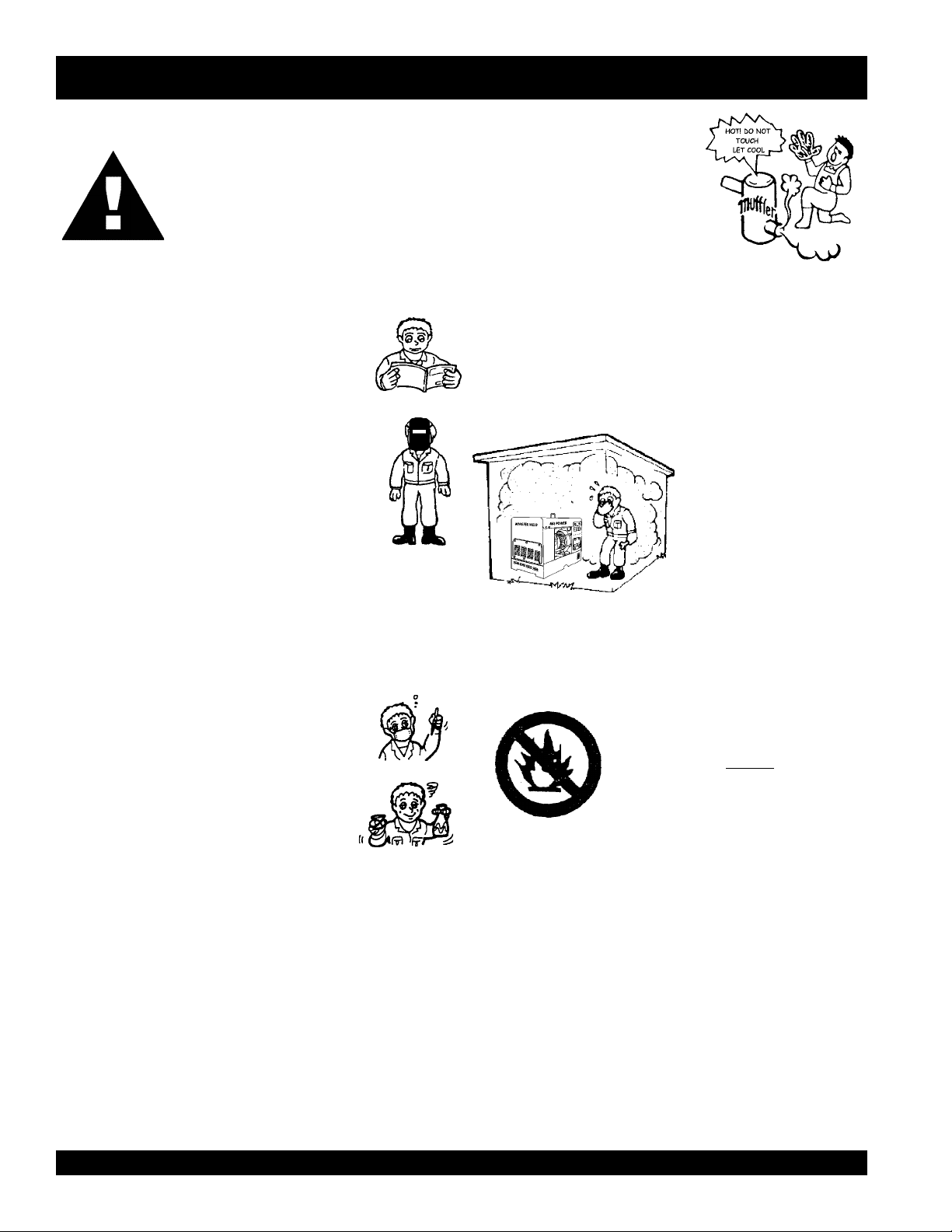
■DO NOT operate or service this equipment before
reading this entire manual.
■This equipment should not be operated by persons
under 18 years of age.
■NEVER operate this equipment without proper
protective clothing that is flame-resistant (wool or
leather), welding shield, ventilator, steel-toed
boots and other protective devices required by
the job.
■NEVER touch the hot exhaust
manifold, muffler or cylinder. Allow
these parts to cool before servicing
engine or welder/AC generator.
■High Temperatures – Allow the engine to cool before adding
fuel or performing service and maintenance functions. Contact
with hot components can cause serious burns.
■The engine of this welder/AC generator requires an adequate
free flow of cooling air. Never operate the welder/AC generator
in any enclosed or narrow area where free flow of the air is
restricted. If the air flow is
restricted it will cause serious
damage to the welder/AC
generator engine and may
cause injury to people. The
engine gives off DEADLY
carbon monoxide gas.
■ Protect others around the welding area with barriers and screens.
Warn others not to stare at the welding arc.
■NEVER operate this equipment when not feeling
well due to fatigue, illness or taking medicine.
■NEVER operate this equipment under the
influence or drugs or alcohol.
■NEVER use accessories or attachments, which are not
recommended by MQ Power for this equipment. Damage to
the equipment and/or injury to user may result.
■Manufacture does not assume responsibility for any accident
due to equipment modifications.
■Whenever necessary, replace nameplate, operation and
safety decals when they become difficult read.
■Always check the machine for loosened threads or bolts before
starting.
■DO NOT weld near flammable liquids.
■Always refuel in a well-ventilated area, away from sparks and
open flames.
Always use extreme caution when
working with flammable liquids. When
refueling, stop the engine and allow it
to cool. DO NOT
the machine. Fire or explosion could
result from fuel vapors, or if fuel is spilled
on a hot engine.
■NEVER operate the welder/AC generator in an explosive
atmosphere or near combustible materials. An explosion or
fire could result causing severe bodily harm or even death.
■Topping-off to filler port is dangerous, as it tends to spill fuel.
■Wear protective ear muffs or ear plugs if noise level is high.
smoke around or near
PAGE 6 —DAW-500S WELDER/A.C. GENERATOR— PARTS & OPERATION MANUAL — REV. #0 (07/19/01)
Page 7
RULES FOR SAFE OPERATION
CAUTION:
This welder/AC generator is a source of
providing LETHAL high voltages. Never
permit unqualified personnel-especially
children to operate the welder/AC generator.
■This welder/AC generator is equipped with a ground terminal
for your protection. Always complete the grounding path from
the welder/AC generator to an external grounding source.
■NEVER operate this welder/AC generator, or handle any
electrical equipment while standing in water, while bare foot,
while hands are wet, or in the rain. Dangerous electrical
shock could occur causing severe bodily harm or even death.
■Arc rays can cause blindness. Always wear protective
shield when welding.
CAUTION:
CAUTION:
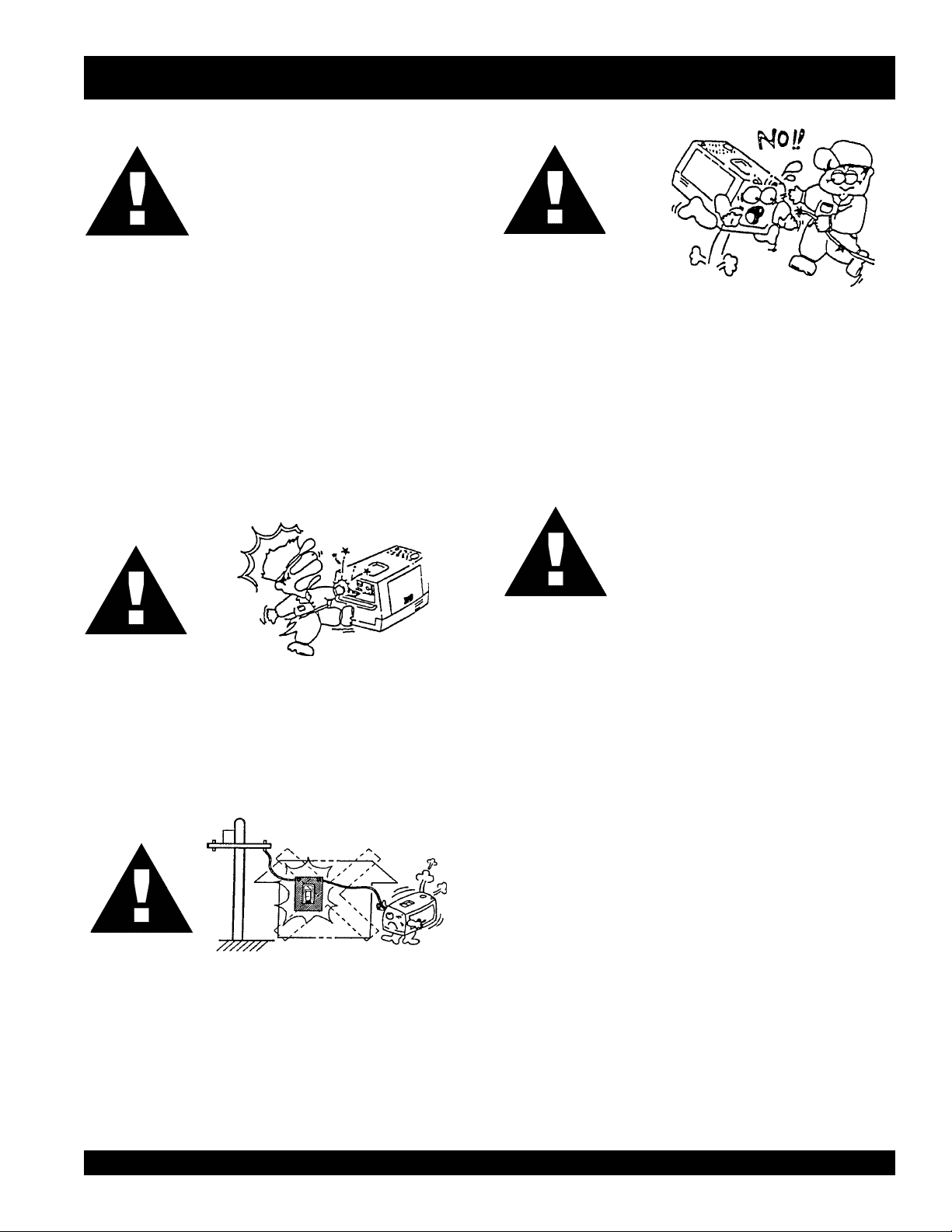
■Never use damaged or worn cables when connecting
power tools or equipment to the welder/AC generator.
Make sure power connecting cables are securely
connected to the generator’s output terminals. Insufficient
tightening of the terminal connections may cause damage
to the welder/AC generator and electrical shock.
CAUTION:
DO NOT touch or open coolant drain plug,
radiator cap, or engine oil drain plug while
the welder/AC generator is running.
Always allow sufficient time for the engine
and generator to cool before performing
maintenance.
■NEVER touch output terminals or electrode during
operation. This is extremely dangerous. Always stop the
machine when contact with the output terminals and
welding electrode.
CAUTION:
■Backfeed to a utility system can cause electrocution and/or
property damage. Do not connect to any building's electrical
system except through an approved device or after building
main switch is opened.
Emergencies
■ Always know the location of the nearest fire extinguisher
and first aid kit. Know the location of the nearest telephone.
Also know the phone numbers of the nearest ambulance,
doctor and fire department. This information will be invaluable
in the case of an emergency.
Maintenance Safety
■ NEVER lubricate components or attempt service on a running
machine.
■ Always allow the machine a proper amount of time to cool
before servicing.
■ Keep the machinery in proper running condition.
■ Fix damage to the machine immediately and always replace
broken parts.
■ Dispose of hazardous waste properly. Examples of potentially
hazardous waste are used motor oil, fuel, coolant and fuel
filters.
■ DO NOT use plastic containers to dispose of hazardous
waste.
■ DO NOT pour waste, oil, coolant or fuel directly onto the
ground, down a drain or into any water source.
DAW-500S WELDER/A.C. GENERATOR — PARTS & OPERATION MANUAL — REV.#0 (07/19/01) — PAGE 7
Page 8
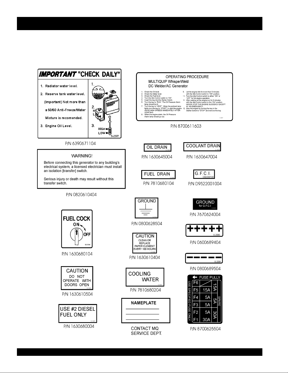
OPERATION AND SAFETY DECALS
Machine Safety Decals
The DAW-500S welder/AC generator is equipped with a number of safety decals. These decals are provided for operator safety and
maintenance information. The illustration below shows these decals as they appear on the machine. Should any of these decals
become unreadable, replacements can be obtained from your dealer.
PAGE 8 —DAW-500S WELDER/A.C. GENERATOR— PARTS & OPERATION MANUAL — REV. #0 (07/19/01)
Page 9
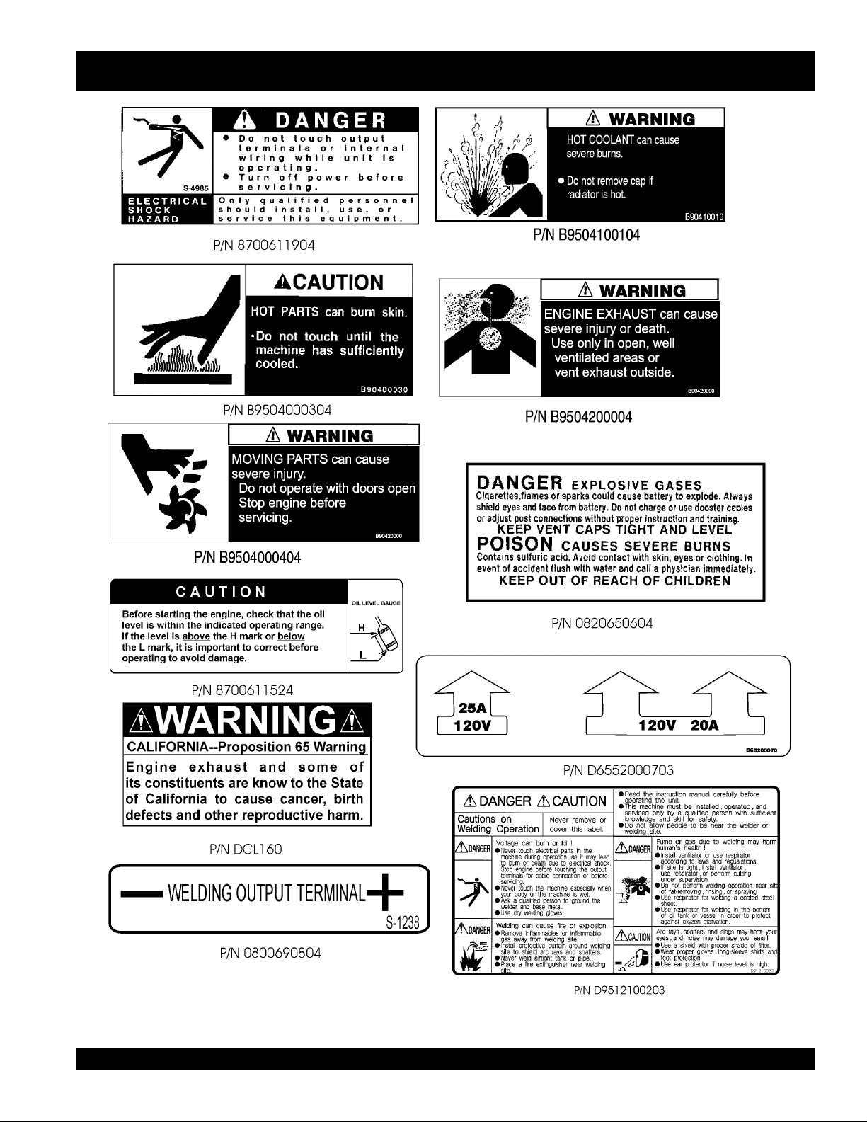
OPERATION AND SAFETY DECALS
DAW-500S WELDER/A.C. GENERATOR — PARTS & OPERATION MANUAL — REV.#0 (07/19/01) — PAGE 9
Page 10

DAW-500S — SPECIFICATIONS
snoitacificepS.1elbaT
snoitacificepSrotareneG
ledoMS005-WAD
esahPelgniS
seriW)dednuorGlartueN(eriW-2
egatloVdetaRstloV021
ycneuqerFzH06
deepSmpr0063
rotcaFrewoP%001
gnitaRsuounitnoC
snoitacificepSredleW
)CC/VC(rewoPtuptuOdetaR Wk9.11/Wk1.71
)CC/VC(egatloVtuptuOdetaR V43/V83
)CC/VC(tnerruCtuptuOdetaR A053/A054
elcyCytuD%001/%06
egnaRegatloV )ylnoVC(stloV04~61
egnaRtnerruC )ylnoCC(spmA005~05
snoitacificepSenignE
ledoM3071DATOBUK
epyTelcyC-4,lacitreV
tuptuOdetaR)Wk4.52(PH1.43
tnemecalpsiD)L746.1(ni.uc4.001
metsySgnilooCdelooc-retaW
metsySgnitratStratS-cirtcelE
yticapaCknaTleuFsretil54/lag9.11
yticapaCtnalooCsretil8.4/lag72.1
yticapaCliOebuLsretil6.5/lag84.1
)gnidlew(noitpmusnoCleuF .rh/)sretil0.5(lag3.1
yrettaBhA56-V21
leuF2.oNleuFleseiD
)HxWxL(snoisnemiD mm078x008x0331
thgieW)gk564(.sbl5201
mpr0082@
)ni43x23x25(
The maximum output of the engine listed above is applicable to supplying electrical power for continuous service at ambient
conditions in accordance with SAE Test cord J607. The above ambient conditions are at standard sea level, with a barometric
reading of 29.92 inches and a temperature of 60 degrees Fahrenheit.
°°
°
°°
Generally, the engine output power will decrease 3 1/2% for each 1000 feet of altitude above sea level, and 1% for each 10
°°
°
Fahrenheit above the standard temperature of 60
°°
F.
F
PAGE 10 —DAW-500S WELDER/A.C. GENERATOR— PARTS & OPERATION MANUAL — REV. #0 (07/19/01)
Page 11

DAW-500S — GENERAL INFORMATION
DAW-500S FAMILIARIZATION
Generator
The MQ Power Model DAW-500S welder/AC generator can
provide 450 amps of welding current when in the CV/DC
mode and 350 amps of welding current when in the CC/DC
mode.
Control Panel
The control panel is provided with the following:
! One GFCI 120 volt receptacle, 20 amp (single-phase)
! One 120 volt receptacle, 30 amp (single-phase)
! Main Circuit Breaker 125V @25 Amps
! Circuit Protector Breaker (GFCI) 120V @20 Amps
! Idle Control Switch
! Starter Switch
! Warning Lamp Unit
! Hour Meter
! Ground Terminal
Engine Protection System
Engine protection fail safe features are provided in the event
of low oil pressure, high coolant temperature and failure of
the battery to charge. If any of the above conditions occur
while operating the welder/AC generator, it will cause a
complete unit shut down.
Battery Charge Indicator
This unit is equipped with a protective device that signals
an indicator and automatically stops the engine when the
battery cannot be charged by the alternator.
Water Temperature Indicator
This unit is equipped with an apparatus that signals an
indicator and automatically stops the engine when the cooling
water temperature becomes abnormally high. This apparatus
will not function properly if the machine is operated with
less than the proper amount of coolant.
Oil Pressure Warning Indicator
In the event of low oil pressure (engine), this welder/AC
generator is equipped with an engine protection fail safe
system . If low oil pressure is detected while operating the
welder/AC generator, the engine protection system will shut
down the engine.
If this condition (low oil pressure) should occur, please refer
to the engine troubleshooting table (page 37) in this manual.
Engine
The DAW-500S is powered by a 4-cycle KUBOTA diesel
engine. This engine is designed to meet every performance
requirement for welder/AC generator. Reference Table 1,
page 10 for engine specifications.
In keeping with MQ Power's policy of constantly improving
its products, the specifications quoted herein are subject to
change without prior notice.
Figures 2 and 3 (pages 13-14) show the basic controls and
indicators for the DAW-500S Welder/AC generator.
Circuit Breakers
To protect the welder/AC generator from an overload,
pole, 25 amp, main circuit breaker is provided. In addition a
single pole, 20 amp breaker is provided for the G.F.C.I.
receptacle. Make sure to switch both circuit breakers to the
"OFF" position prior to starting the engine.
General Inspection Prior to Operation
The DAW-500S utilizes a welder/AC generator that has been
thoroughly inspected and accepted prior to shipment from
the factory. However, be sure to check for damaged parts or
components, or loose nuts and bolts, which could have
occurred in transit.
a single-
DAW-500S WELDER/A.C. GENERATOR — PARTS & OPERATION MANUAL — REV.#0 (07/19/01) — PAGE 11
Page 12
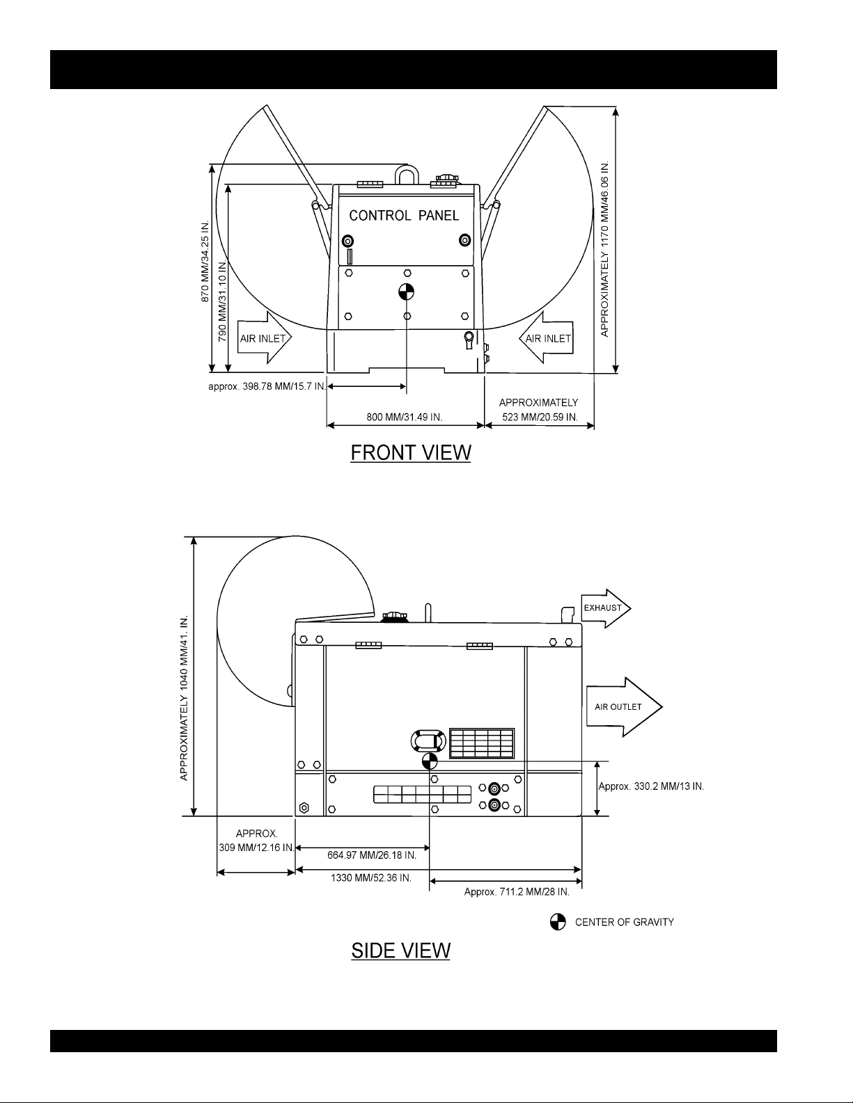
DAW-500S — DIMENSIONS
Dry Weight: 1,025 lbs.
Figure 1. DAW-500S Dimensions
PAGE 12 —DAW-500S WELDER/A.C. GENERATOR— PARTS & OPERATION MANUAL — REV. #0 (07/19/01)
Total Weight: 1,150 lbs.
Page 13
DAW-500S — CONTROLS AND INDICATORS
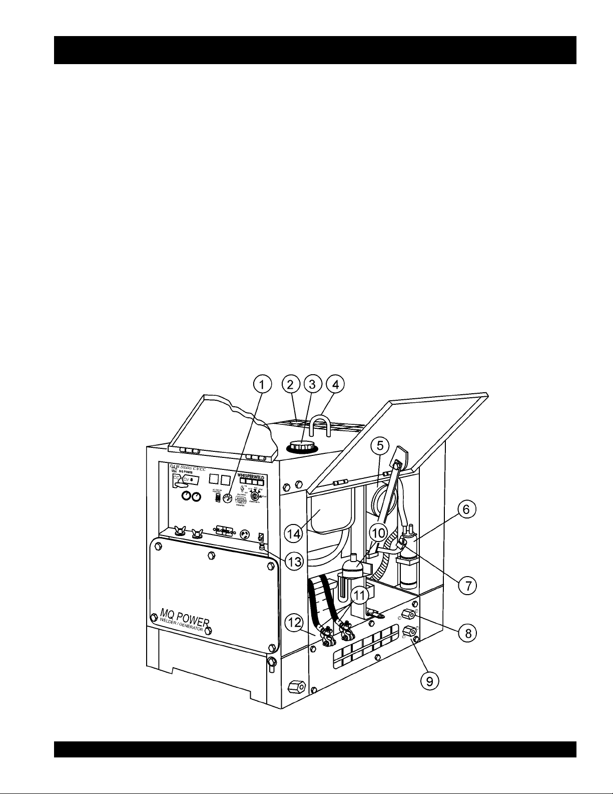
Figures 2 and 3 show the location of the controls and indicators.
The functions of each control or indicator is described below
and on the preceding page.
1. Fuel Gauge – Indicates the amount of fuel in the fuel tank.
2. Air Outlet Exhaust – Allows engine exhaust to exit the
welder/AC generator into the open air. NEVER block this
opening.
3. Fuel Cap – Remove this cap to add fuel. Add only #2
diesel fuel. Always keep an adequate amount of fuel in the
tank. DO NOT top off. Wipe up any spilled fuel immediately.
4. Lifting Hook – Use this hook to lift the welder/AC
generator.
5. Engine Air Cleaner – Prevents dirt and other debris from
entering the fuel system. Lift locking latch on air filter
cannister to gain access to filter element.
6. Overflow Bottle – Supplies coolant to the radiator when
radiator coolant level is low. Fill to indicated level as shown
on bottle.
7. Engine Oil Filler Port – Remove this cap to add engine
oil. Use only recommended type oil. See table 3, page 16.
8. Coolant Drain Plug – Remove this plug to drain coolant
from the radiator.
9. Oil Drain Plug – Remove this plug to drain oil from the
engine.
10. Automatic Speed Control Solenoid – Automatically
regulates engine speed.
11. Battery Terminals – Connect these terminals to the battery.
Always pay close attention to the polarity of the terminals
when connecting to the battery, RED (positive), and BLACK
(negative).
12. Battery – Provides +12 VDC power for the welder/AC
generator. When replacing battery (12V 35 AH) use only
recommended type battery.
13. G.F.C.I Ground Terminal – Use this terminal to connect
external equipment grounds so that the GFCI receptacle
will have a ground path.
14. Fuel Tank – Holds 6.6 gallons (25 liters) of diesel fuel.
Figure 2. Controls and Indicators
DAW-500S WELDER/A.C. GENERATOR — PARTS & OPERATION MANUAL — REV.#0 (07/19/01) — PAGE 13
Page 14
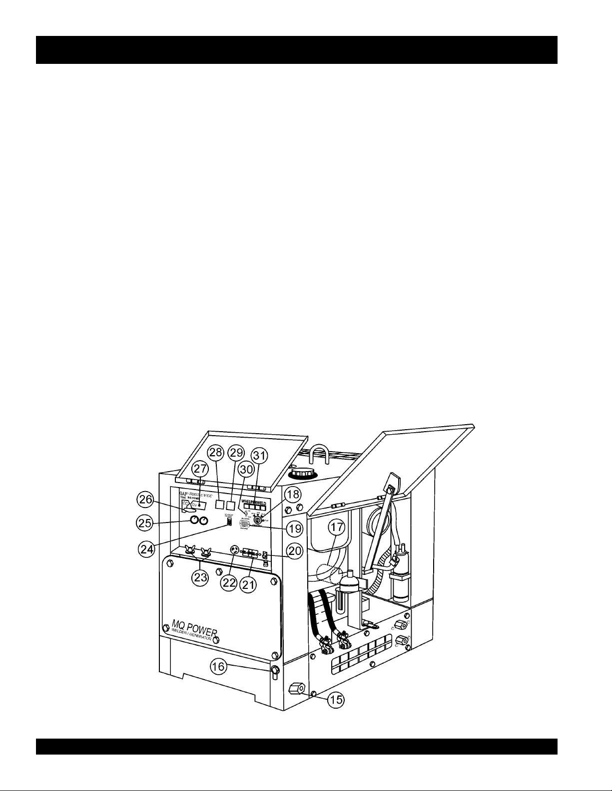
DAW-500S — CONTROLS AND INDICATORS
15. Fuel Drain Plug – Remove this plug to drain fuel from the
fuel tank.
16. Frame Ground Lug – Connect a ground strap between
this lug and a ground rod. Make sure the ground rod is
inserted deep into the ground to provide a good earth
ground. Consult with local Electrical and Safety Codes for
proper connection.
17. Oil Filter – Provides oil filtering for the engine.
18. Ignition Switch – With key inserted turn clockwise to start
engine.
19. Hour Meter – Indicates number of hours machine has
been in use or hours engine was run.
20. Circuit Protector Circuit Breaker – This single pole circuit
breaker provides circuit protection (120V @20 amps) for
the G.F.C.I. receptacle.
21. Receptacle G.F.C.I. – This receptacle provides 120 volts
output at 20 amps.
22. Receptacle – Provides 120 volts output at 25 amps.
23. Welding Output Terminals – Connect the welding cable
to this terminal. Select the appropriate polarities according
to the application. See Table 7.
24. Main Circuit Breaker – This single-pole circuit breaker
provides circuit protection (125V @25 amps) for the electric
parts assembly.
25. Current Control (CC) Voltage Control (CV) Adjustment
Knobs – Use these controls to adjust welding current and
voltage.
26. Welding Type (Wire/Stick) Selector Switch (CV/CC) –
Turn this selector switch to either the CV or CC for welding.
DO NOT turn this switch under load.
27. Sub-Selector Switch-This switch is used to select type of
welding and welding voltage needed. This switch will not
work in CC mode.
28. DC Voltmeter- Indicated the amount of voltage used during
welding in CV mode.
29. DC Ammeter- Indicates the amount of amperage being
used during welding in CC mode.
30. Idle Control Switch – Regulates the engine speed when
the welder/AC generator is under load.
31. Warning Lamp Display – Lights red when the following
conditions occur:
! Low Oil Pressure
! High Water Temperature
! Electrical System Is Not Charging Properly
! Preheat Indicator
Figure 3. Controls and Indicators (con't)
PAGE 14 —DAW-500S WELDER/A.C. GENERATOR— PARTS & OPERATION MANUAL — REV. #0 (07/19/01)
Page 15

DAW-500S — TRAILER-SAFETY GUIDELINES
CAUTION:
ALWAYS make sure the trailer is in good
operating condition. Check the tires for
proper inflation and wear. Also check the
wheel lug nuts for proper tightness.
Explanation of Chart:
This section is intended to provide the user with trailer service and maintenance information. The service and maintenance guidelines referenced in this section apply a wide
range of trailers. Remember periodic inspection of the trailer
will ensure safe towing of the equipment and will prevent
damage to the equipment and personal injury.
It is the purpose of this section to cover the major maintenance components of the trailer. The following trailer components will be discussed in this section:
" Brakes
" Tires
" Lug Nut Torquing
" Suspension
" Electrical
" Brake Troubleshooting Tables
Use the following definitions while reading Table 2.
1. Fuel Cell - Provides an adequate amount of fuel for
the equipment in use. Fuel cells must be empty when
transporting equipment.
2. Braking System - System employed in stopping the
trailer. Typical braking systems are electric, surge, hydraulic, hydraulic-surge and air.
7. Coupler - Type of hitch used on the trailer for towing.
8. Tire Size - Indicates the diameter of the tire in inches
(10,12,14, etc.), and the width in millimeters
(175,185,205, etc.). The tire diameter must match the
diameter of the tire rim.
9. Tire Ply - The tire ply (layers) number is rated in letters;
2-ply,4-ply,6-ply, etc.
10. Wheel Hub - The wheel hub is connected to the trailer’s
axle.
11. Tire Rim - Tires are mounted on a tire rim. The tire rim
must match the size of the tire.
12. Lug Nuts - Used to secure the wheel to the wheel hub.
Always use a torque wrench to tighten down the lug
nuts. See Table 4 and Figure 5 for lug nut tightening and
sequence.
13. Axle - Indicates the maximum weight the axle can sup-
port in pounds, and the diameter of the axle expressed
in inches (see Table 3 on page 17). Please not that
some trailers have a double axle. This will be shown as
2-6000 lbs., meaning two axles with a total weight capacity of 6000 pounds.
14. Suspension - Protects the trailer chassis from shock
transmitted through the wheels. Types of suspension
used are leaf, Q-flex, and air ride.
15. Electrical - Electrical connectors (looms) are provided
with the trailer so the brake lights and turn signals can
be connected to the towing vehicle. See page 16 for
proper wiring connections.
16. Application - Indicates which units can be employed
on a particular trailer.
3. GVWR- Gross Vehicle Weight Rating (GVWR), is the
maximum number of pounds the trailer can carry, including the fuel cell (empty).
4. Frame Length - This measurement is from the ball
hitch to the rear bumper (reflector).
5. Frame Width - This measurement is from fender to
fender.
6. Jack Stand - Trailer support device with maximum
pound requirement from the tongue of the trailer.
DAW-500S WELDER/A.C. GENERATOR — PARTS & OPERATION MANUAL — REV.#0 (07/19/01) — PAGE 15
Specifications may change without notice. Contact MQ
Power Sales for information of specific trailer to unit.
Page 16

DAW-500S — TRAILER-SPECIFICATIONS
snoitacificepS.2elbaT
LEDOM NOITACILPPA LEUF
LLEC
51-01-RLRT ,51ACD,21-GLT
003-WLT
X01-RLRT ,51ACD,21-GLT
003-WLT
FX01-RLRT ,51ACD,21-GLT
003-WLT
W522-RLRT 01-ACDONONSBL0022"58"24.BL008
004-WLB 004-WLBONCIRTCELESBL0072"451TSAM/W
FX51-RLRT 51-ACDLAG14ONSBL0072"421"55.BL008
X05-RLRT 52-ACDONONSBL0072"421"55.BL008
FX05-RLRT 52-ACDLAG14ONSBL0072"421"55.BL008
TBS52-RLRT 52-ACDONONSBL0992"021"66.BL008
W07-RLRT 07,06-,54-ACDONEGRUSSBL0007"681"77.BL0002
X07-RLRT 07,06-,54-ACDTPOEGRUSSBL0007"831"66.BL0002
FX07-RLRT 07,06-,54-ACDLAG35EGRUSSBL0007"831"66.BL0002
FX001-RLRT 521,001-ACDLAG051EGRUSCILUARDYHSBL0007"091"67.BL0002
521/58-RLRT ,001,58-ACD
521
FX051-RLRT 081,051-ACDLAG002EGRUSCILUARDYHSBL06111"402"48.BL0005
FX022-RLRT 022-ACDLAG052EGRUSCILUARDYHSBL00041"222"38.BL0005
FX003-RLRT 003-ACDLAG052EGRUSCILUARDYHSBL00081"832"38.BL0005
FX004-RLRT 004-ACDLAG053CIRTCELESBL00081"832"38.BL0005
FX006-RLRT 008,006-ACDLAG055RIASBL00003"483"69.BL0005
XS008-RLRT 008,006-ACDLAG055RIASBL00003"483"69.BL0005
ONONSBL0091"69"05.BL008
ONONSBL0091"69"05.BL008
LAG15ONSBL0091"69"05.BL008
LAG541CILUARDYHSBL00001"681"77.BL0002
EKARB
METSYS
RWVG EMARF
EMARF
HTGNEL
"421O/W
HTDIW
"55
)LLAT"87(
KCAJ
DNATS
LEEHWTLITLLUF
LEEHWTLITLLUF
LEEHWTLITLLUF
LEEHWTLITLLUF
.BL008
LEEHWTLITLLUF
LEEHWTLITLLUF
LEEHWTLITLLUF
LEEHWTLITLLUF
LEEHWTLITLLUF
DAPTALF
DAPTALF
DAPTALF
DAPTALF
DAPTALF
DAPTALF
DAPTALF
DAPTALF
DAPTALF
DAPTALF
DAPTALF
PAGE 16 —DAW-500S WELDER/A.C. GENERATOR— PARTS & OPERATION MANUAL — REV. #0 (07/19/01)
Page 17

DAW-500S — TRAILER-SPECIFICATIONS
)t'noC(snoitacificepS.2elbaT
LEDOM RELPUOC SERIT SLEEHW ELXA SBUH NOISNEPSUS LACIRTCELE
W51-01-RLRT SSALCLLAB"2
ELBATSUJDA2
X01-RLRT SSALCLLAB"2
ELBATSUJDA2
FX01-RLRT SSALCLLAB"2
ELBATSUJDA2
W522-RLRT SSALCLLAB"2
ELBATSUJDA2
004WLB SSALCLLAB"2
ELBATSUJDA2
FX51-RLRT SSALCLLAB"2CRL31-87B"05.4X"31"2/1-2#0053GUL5FAEL4REBBURELOP4
X05-RLRT SSALCLLAB"2CRL31-87B"05.4X"31.sbl0053
FX05-RLRT SSALCLLAB"2CRL31-87B"05.4X"31.sbl0053
W07-RLRT SSALCLLAB"2
ELBATSUJDA"3
X07-RLRT SSALCLLAB"2
ELBATSUJDA"3
FX07-RLRT SSALCLLAB"2
ELBATSUJDA"3
FX001-RLRT 6/5-2ELBATSUJDA
EYE"3TPO
521/58-RLRT 6/5-2ELBATSUJDA
EYE"3TPO
FX051-RLRT EYELLAB"3E61-057
FX022-RLRT EYE"3
ELBATSUJDA
FX003-RLRT EYE"3
ELBATSUJDA
FX004-RLRT EYE"3
ELBATSUJDA
FX006-RLRT LEEHWHT5H5.71R57/512TS
RA008-RLRT LEEHWHT5H5.71R57/512TS
C31-571"05.4X"312X2#0022GUL5FAEL3/WMOOLERIW4
C31-571"5.4X"312X2#0022GUL5FAEL3TALFELOP4
C31-571"5.4X"312X2#0022GUL5FAEL3TALFELOP4
B31-571"5.4X312X2#0022GUL5XELFQTALFELOP4
C31-571"5.4X312X2#0022GUL5FAEL3TALFELOP4
"8/3-2
"8/3-2
C41-502
)4(SAIB
C41-502
)4(SAIB
C41-502
)4(SAIB
C51-502
)4(SAIB
D51R57/522TS
)4(LAIDAR
)4(SAIB
E61R58/532TS
)4(LAIDAR
E61R58/532TS
)6(LAIDAR
E61R58/532TS
)6(LAIDAR
)8(LAIDAR
)8(LAIDAR
"5X"41.sbl0053
"3
"5X"41sbl0053
"3
"5X"41.sbl0053
"3
"5.5X"41sbl0053
"3
"6x"41sbl0006-)2(GUL6FAEL7MOOLERIW4
"7X"61sbl0006-)2(GUL8FAEL7MOOLERIW4
"7X"61sbl0007-)2(GUL8XELFQMOOLERIW4
"7X"61sbl0006-)2(GUL8XELFQMOOLERIW4
"7X"61.sbl0007-)3(GUL8XELFQMOOLERIW4
"7X"61sbl00001-)3(GUL8FAEL7MOOLERIW6
"7X"61sbl00001-)3(GUL8EDIR-RIAMOOLERIW6
GUL5FAEL4REBBURELOP4
GUL5FAEL4REBBURELOP4
GUL5FAEL5REBBURELOP4
GUL5FAEL5REBBURELOP4
GUL5FAEL5REBBURELOP4
GUL5FAEL5MOOLERIW4
TALFELOP4
TALF
TALF
TALF
TALF
TALF
TALF
DAW-500S WELDER/A.C. GENERATOR — PARTS & OPERATION MANUAL — REV.#0 (07/19/01) — PAGE 17
Page 18
DAW-500S — TRAILER TIRES & SUSPENSION
Tires/Wheels/Lug Nuts
Tires and wheels are a very important and critical
components of the trailer. When specifying or replacing
the trailer wheels it is important the wheels, tires, and axle
are properly matched.
CAUTION:
DO NOT attempt to repair or modify a
wheel. DO NOT install an inner tube to
correct a leak through the rim. If the
rim is cracked, the air pressure in the
inner tube may cause pieces of the rim
to explode (break off) with great force and cause serious
eye or bodily injury.
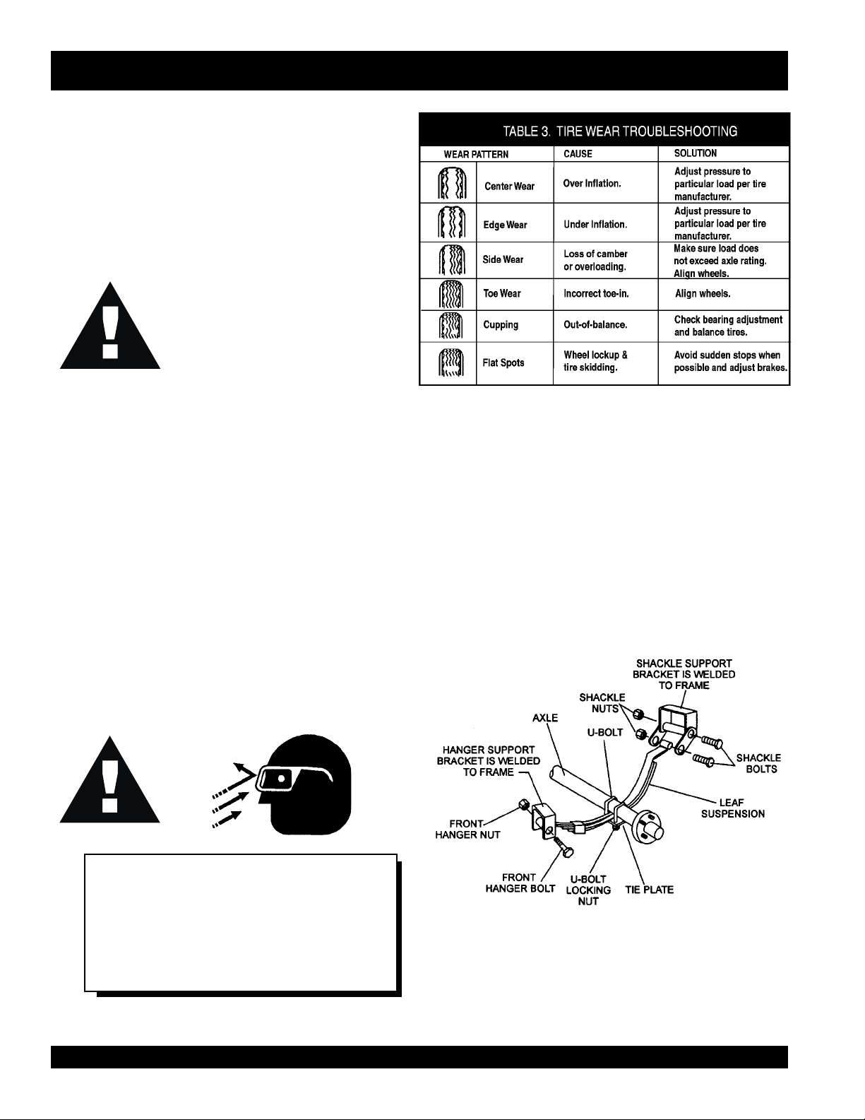
Tire Wear/Inflation
Tire inflation pressure is the most important factor in
preserving tire life. Pressure should be checked cold before
operation. DO NOT bleed air from tires when they are hot.
Check inflation pressure weekly to insure the maximum
tire life and to prevent premature tread wear.
Table 2 (Tire Wear Troubleshooting) will help pinpoint the
causes and solutions of tire wear problems.
Suspension
The leaf suspension springs and associated components
(Figure 4) should be visually inspected every 6,000 miles
for signs of excessive wear, elongation of bolt holes, and
loosening of fasteners. Replace all damaged parts
(suspension) immediately. Torqued suspension components
as detailed in Table 4.
CAUTION:
NOTE
ALWAYS wear safety glasses when removing
or installing force fitted parts. Failure to
comply may result in serious injury.
PAGE 18 —DAW-500S WELDER/A.C. GENERATOR— PARTS & OPERATION MANUAL — REV. #0 (07/19/01)
Figure 4. Suspension Components
Page 19
metI ).sbL-.tF(euqroT
TLOB-U"8/353-XAM03-NIM
TLOB-U"61/706-XAM54-NIM
TLOB-U"2/106-XAM54-NIM
DAW-500S — TRAILER TIRES & SUSPENSION
stnemeriuqeReuqroTnoisnepsuS.4elbaT
SHACKLE BOLT
SPRING EYE BOLT
SHOULDER TYPE
SHACKLE BOLT
SNUG FIT ONLY.PARTS MUST ROTATE FREELY
LOCKING NUTS OR COTTER PINS ARE PROVIDE D T O
-
RETAIN NUT
BOLT ASSEMBLY
.
05-XAM03-NIM
.
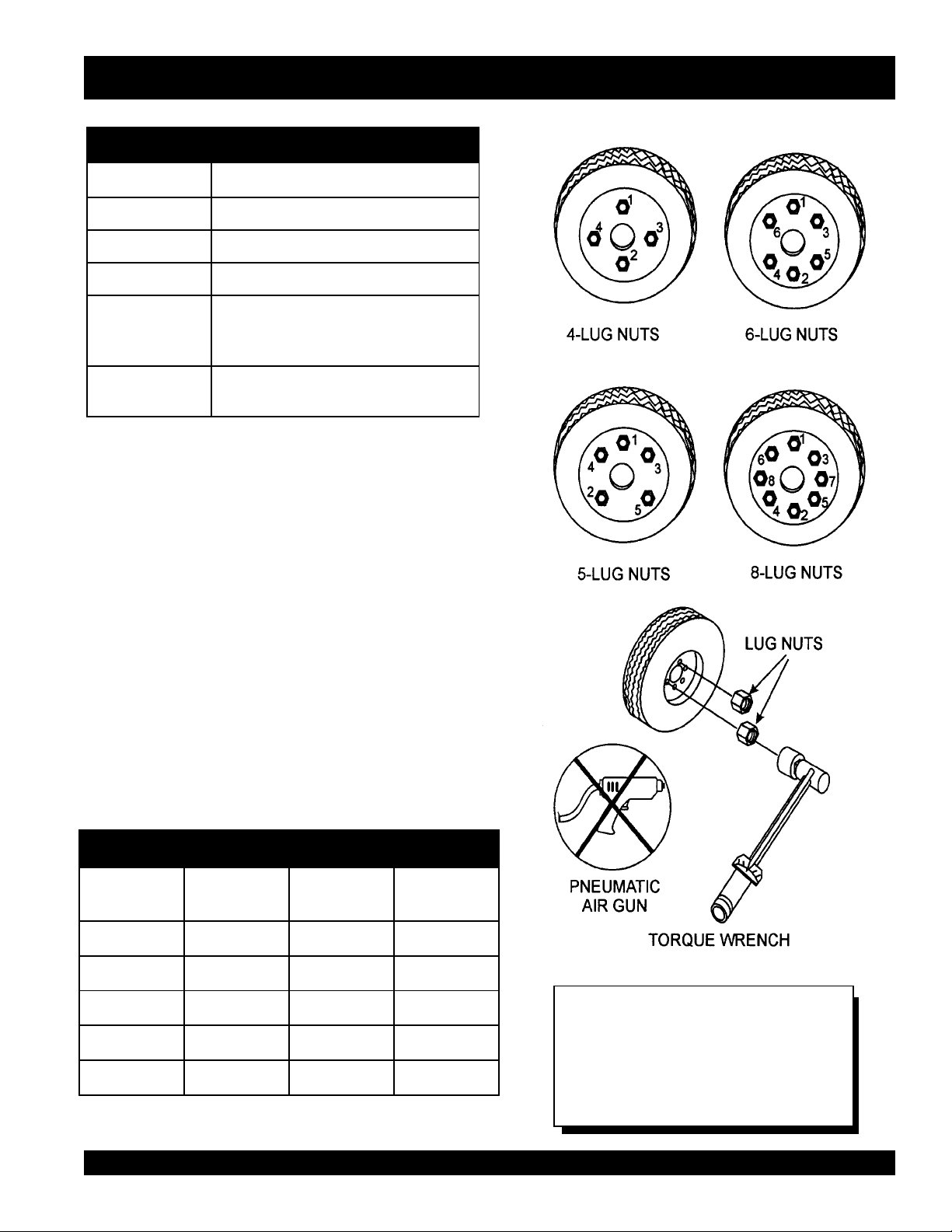
Lug Nut Torque Requirements
It is extremely important to apply and maintain proper wheel
mounting torque on the trailer. Be sure to use only the
fasteners matched to the cone angle of the wheel. Proper
procedure for attachment of the wheels is as follows:
1. Start all wheel lug nuts by hand.
2. Torque all lug nuts in sequence. See Figure 5. DO
NOT torque the wheel lug nuts all the way down. Tighten
each lug nut in 3 separate passes as defined by Table
5.
3. After first road use, retorque all lug nuts in sequence.
Check all wheel lug nuts periodically for continued safe
operation.
stnemeriuqeReuqroTeriT.5elbaT
eziSleehWssaPtsriF
SBL-TF
"2152-0204-5356-05
"3152-0204-5356-05
"4152-0206-05021-09
"5152-0206-05021-09
"6152-0206-05021-09
DAW-500S WELDER/A.C. GENERATOR — PARTS & OPERATION MANUAL — REV.#0 (07/19/01) — PAGE 19
ssaPdnoceS
SBL-TF
ssaPdrihT
SBL-TF
Figure 5. Lug Nut Tightening Sequence
NOTE
NEVER use an pneumatic air gun to
tighten wheel lug nuts.
Page 20
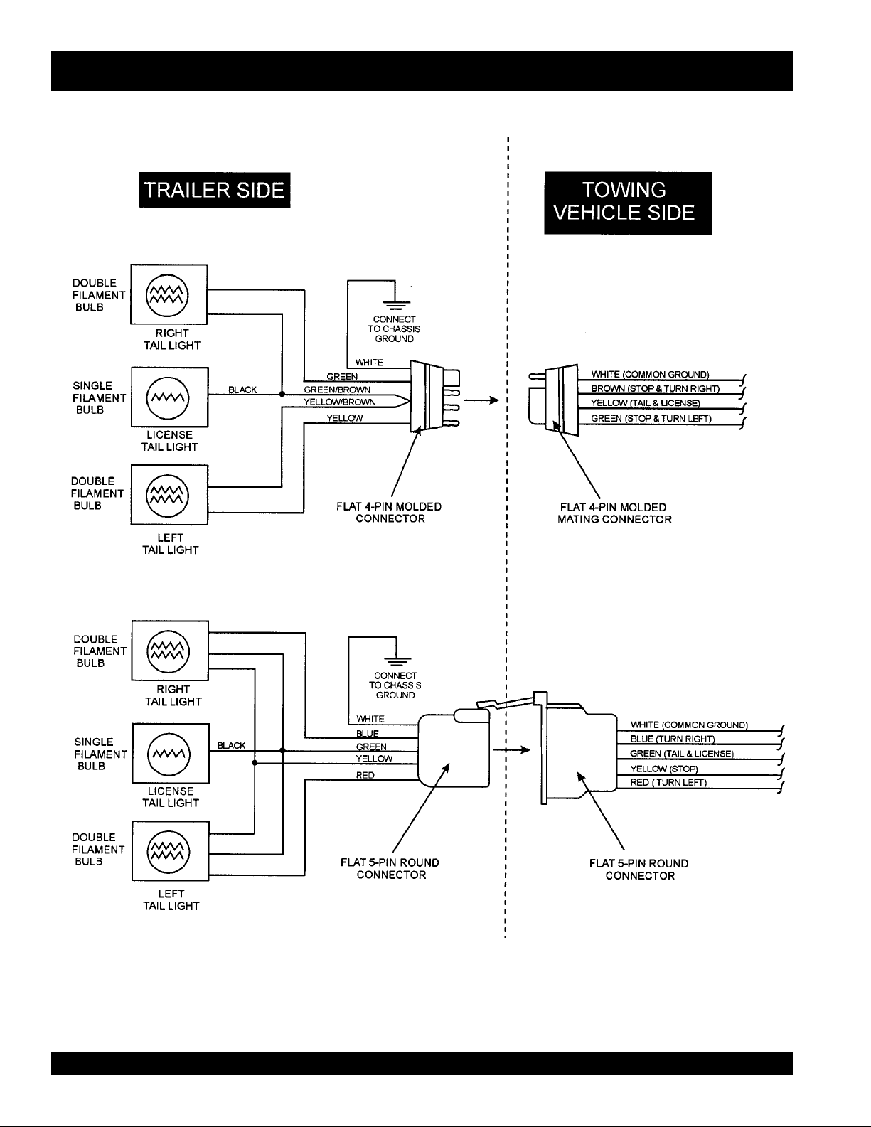
DAW-500S — TRAILER WIRING DIAGRAMS
NOTE:
LIGHTS ARE ORIENTED FROM THE DRIVER’S SEAT
PAGE 20 —DAW-500S WELDER/A.C. GENERATOR— PARTS & OPERATION MANUAL — REV. #0 (07/19/01)
Page 21

DAW-500S — INSTALLATION
Outdoor Installation
Install the welder/AC generator in a location where it will not
be exposed to rain or sunshine. Make sure the welder/AC
generator is on secure level ground so it cannot slide or
shift around. Do not operate machine with inclination of
more than 5 degrees. Also install the welder/AC generator
so the exhaust will not be discharged in the direction of
nearby homes.
The installation site must be relatively free from moisture
and dust. All electrical equipment should be protected from
excessive moisture. Failure to do will result in deterioration
of the insulation, and will result in short circuits.
Foreign materials such as dust, sand, lint and abrasive
materials will cause excessive wear to engine and alternator
parts.
CAUTION :
Indoor Installation
Exhaust gases from diesel engines are extremely poisonous.
Whenever an engine is installed indoors the exhaust fumes
must be vented to the outside. The engine should be installed
at least two feet away from any wall. Using an exhaust pipe
which is too long or too small can cause excessive back
pressure and cause the engine to heat excessively.
Eliminate the danger of deadly carbon monoxide gas.
Remember that exhaust fumes from any diesel engine are
very poisonous if discharged in a closed room, but harmless
if allowed to mix with the outside air. If the welder/AC
generator is installed indoors, you must make provisions for
venting the engine exhaust to the outside of the building.
Pay close attention to ventilation when
operating the welder/AC generator inside
tunnels and caves. The engine exhaust
contains noxious elements.
DAW-500S WELDER/A.C. GENERATOR — PARTS & OPERATION MANUAL — REV.#0 (07/19/01) — PAGE 21
Page 22
DAW-500S — PRE-SETUP
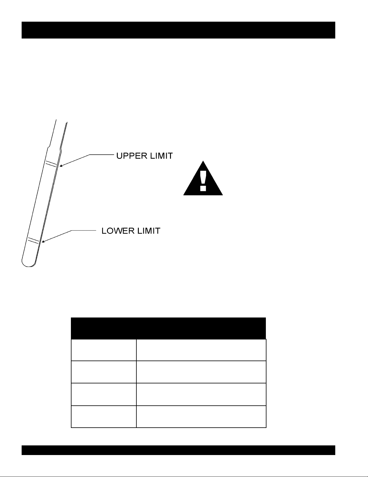
Lubrication Oil
Fill the engine crankcase with lubricating oil through the filler
hole, but do not overfill. Make sure the welder/AC generator
is level. With the dipstick inserted all the way, but without
being screw into the filler hole, verify that the oil level is
maintained between the two notches (Figure 6) on the
dipstick. Use grade CC or higher when refilling. See Table 6
for proper selection of engine oil.
Fuel
Fill the fuel tank with clean diesel fuel. Do not fill the tank
beyond capacity.
Pay attention to the fuel tank capacity when replenishing
fuel. Refer to the fuel tank capacity listed on page 10
Specification Table 1.
The fuel tank cap must be closed tightly after filling. Handle
fuel in a safety container. If the container does not have a
spout, use a funnel.
CAUTION :
Never fill the fuel tank while the engine is
running or in the dark. Fuel spillage on a
hot engine can cause a fire or explosion.
If fuel spillage occurs, wipe up the spilled
gasoline completely to prevent fire
hazards.
Coolant
Figure 6. Engine Oil Dipstick
egnaRerutarepmeT)rehgihrossalcCC(liOepyT
F°32~F°401
)C°5-~C°04(
F°5~F°32
)C°51-~C°5-(
Use only drinkable tap water. If hard water or water with
many impurities is used, the inside of the engine and radiator
may become coated with deposits and cooling efficiency
will be reduced.
An anticorrosion additive added to the water will help prevent
deposits and corrosion in the cooling system. See the
Kubota Engine Operator's Manual for further details.
liOrotoMdednemmoceR.6elbaT
04W01EAS
03-W01EASroW02EAS
)°51-(C°5woleB03-W01EASroW01EAS
PAGE 22 —DAW-500S WELDER/A.C. GENERATOR— PARTS & OPERATION MANUAL — REV. #0 (07/19/01)
Page 23
DAW-500S — PRE-SETUP
CAUTION :
When adding coolant or antifreeze to the
radiator, do not remove the radiator cap
until the unit has completely cooled.
Day-to-day addition of coolant or
antifreeze is done from the reserve tank. See Table 7 for
engine, radiator and reserve tank coolant capacities. Make
sure the coolant level in the reserve tank is always between
the "H" and the "L" markings.
yticapaCtnalooC.7elbaT
rotaidaRdnaenignE)L8.4(.laG72.1
knaTevreseR)L1(.laG61.0
Day-to-day addition of coolant is done from the
Operation in Freezing Weather
When operating in freezing weather, be certain that the proper
amount of antifreeze has been added. See Table 8 for
antifreeze operating temperatures.
Cleaning the Radiator
The radiator may overheat if the fins become overloaded
with dust or debris. Periodically clean the radiator fins with
compressed air. Change the radiator fluid every two yearsl
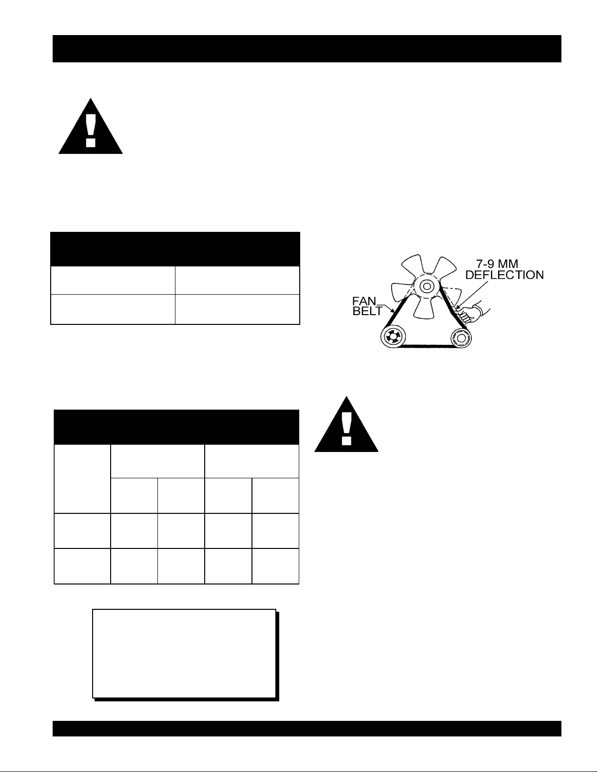
Fan Belt Tension
The deflection of the fan belt may contribute to overheating,
or to insufficient charging of the battery. Inspect and adjust
it in accordance with the Kubota Engine Operator's
Manual.
The fan belt tension is proper if the fan belt (Figure 7) deflects
7 to 9 mm (0.28- to 0.35 in.) when depressed with the thumb
as shown in Figure 5 below.
Figure 7. Fan Belt Tension
CAUTION :
serutarepmeTgnitarepOezeerF-itnA.8elbaT
tnioPgnizeerFtnioPgnilioB
%loV
ezeerF-itnA
C° F° C° F°
0442-21-601222
0573-43-801622
NOTE
When the antifreeze is mixed with
water, the antifreeze mixing ratio must
be less than 50%.
Never place hands near the belts or fan
while the welder/AC generator is running.
Air Cleaner
Periodic cleaning/replacement is necessary. Inspect it in
accordance with the Kubota Engine Operator's Manual.
Battery
Connect the battery to correct polarity. DO NOT connect in
reverse.
Always maintain battery fluid level between the specified
marks. Battery life will be shortened, if the fluid level is not
properly maintained. Add only distilled water when
replenishment is necessary.
The battery is sufficiently charged if the specific gravity of
the battery fluid is 1.28 (at 68° F). If the specific gravity
should fall to 1.245 or lower, it indicates that the battery is
dead and needs to be recharged or replaced.
Check to see whether the battery cables are loose. Poor
contact may result in poor starting or malfunctions, always
keep the terminals firmly tightened. Coating the terminals
with a thin film of grease will help to inhibit corrosion.
DAW-500S WELDER/A.C. GENERATOR — PARTS & OPERATION MANUAL — REV.#0 (07/19/01) — PAGE 23
Page 24

DAW-500S — INSTRUMENTATION
CAUTION :
When using a combination of dual
receptacles, total load should not exceed
the rated capacity of the welder/AC
generator set.
Power Outlets
The welder/AC generator has the following single-phase 60
Hz, 120 volt receptacles.
Single Phase
One Duplex NEMA (GFCI) 5-20R (120V, 20 Amp)
One Twist Lock NEMA L5-30R (120V, 30 Amp)
Main Circuit Breaker (Single-Pole)
This single-pole, 25 amp breaker protects the welder/AC
generator from short circuiting or overloading from the 60
Hz single-phase load.
GFCI Protection Breaker (Single-Pole)
This single-pole, 20 amp breaker protects the GFCI
receptacle from short circuiting or overloading.
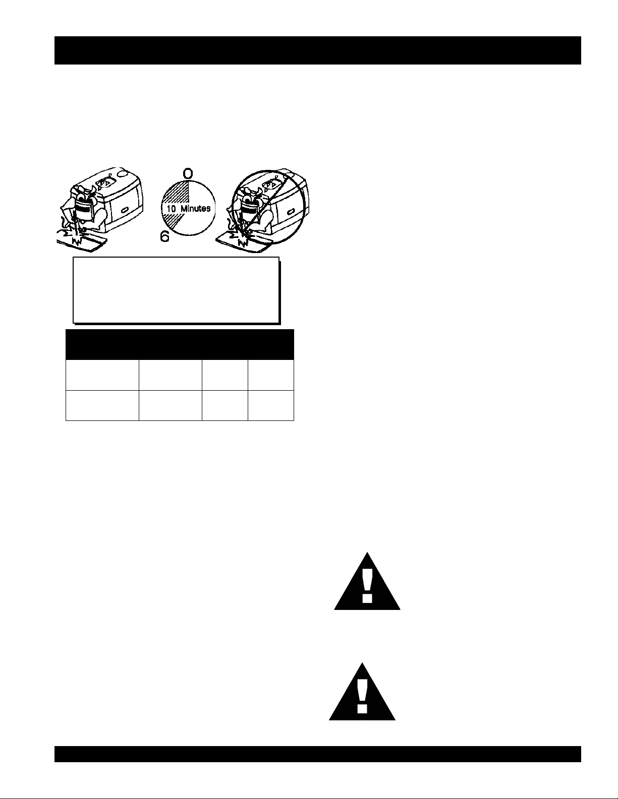
Idle Control Switch
The DAW-500S Welder/AC generator is provided with an
automatic idle (engine) control capability for noise
suppression and fuel cost reduction. The automatic idle
control feature automatically engages under a no-load
condition.
When the Idle Control Switch is placed in the “ON” position,
the engine revolutions will be approximately 2000 rpm (lowspeed operation). When a load is connected to one of the
output receptacles, the engine speed will automatically
increase to about 2800 rpm (high-speed operation) within 10
seconds. Conversely, when the load is removed, the engine
speed will automatically drop back down to 2000 rpm within
10 seconds.
With AC loads of more than 150W (such as lighting
equipment, motor-powered tools, submersible water pumps,
etc.), the engine runs at high speed. When a no load condition
is produced, the engine automatically slows down.
Turn the idle control switch to the “ON” (up) position when
AC loads of more than 200W are connected. Turn the idle
control switch to the “OFF” (down) position when AC loads
of less than 100W or when a magnetic switch is used, or if
very high quality of welding result is required.
However, when welding in CV Low, the engine will continue
to run at a low speed, even when appling AC loads.
GFCI Receptacle
Before connecting a load to the generator's GFCI receptacle,
push the "Test Button" on the front of receptacle before
connecting the load, to confirm that the receptacle is
functioning correctly.
PAGE 24 —DAW-500S WELDER/A.C. GENERATOR— PARTS & OPERATION MANUAL — REV. #0 (07/19/01)
Page 25
DAW-500S — LOAD APPLICATION
Single Phase Load
Always be sure to check the nameplate on the welder/AC
generator and equipment to insure the wattage, amperage
and frequency requirements are satisfactorily supplied by
the welder/AC generator for operating the equipment.
Generally, the wattage listed on the nameplate of the
equipment is its rated output. Equipment may require 130—
150% more wattage than the rating on the nameplate, as
the wattage is influenced by the efficiency, power factor and
starting system of the equipment.
NOTE
If wattage is not given on the
equipment's name plate, approximate
wattage may be determined by
multiplying nameplate voltage by the
nameplate amperage.
WATTS = VOLTAGE x AMPERAGE
The power factor of this welder/AC generator is 1.0. See
Table 9 below when connecting loads.
CAUTION:
Motors and motor-driven equipment draw
much greater current for starting than
during operation.
An inadequate size connecting cable which cannot carry
the required load can cause a voltage drop which can burn
out the appliance or tool and overheat the cable.
The idle control is operated at minimum load capacity of
100W. If the load capacity is less than 100W, change the
idle control switch to the "OFF" position.
CAUTION:
Before connecting this welder/AC
generator to any building’s electrical
system, a licensed electrician must install
an isolation (transfer) switch. Serious injury
or death may result without this transfer
switch.
daoLyBrotcaFrewoP.9elbaT
daoLfOepyTrotcaFrewoP
srotomnoitcudniesahp-elgniS57.0-4.0
spmaltnecsednacni,sretaehcirtcelE0.1
spmalyrucrem,spmaltnecseroulF9.0-4.0
tnempiuqenoitacinummoc,secivedcinortcelE0.1
! When connecting a resistance load such as an
incandescent lamp or electric heater, a capacity of up
to the generating set’s rated output (kW) can be used.
! When connecting a fluorescent or mercury lamp, a
capacity of up to the generating set’s rated output (kW)
multiplied by 0.6 can be used.
! When connecting an electric drill or other power tools,
pay close attention to the required starting current
capacity.
When connecting ordinary power tools, a capacity of up to
the generating set’s rated output (kW) multiplied by 0.8 can
be used.
DAW-500S WELDER/A.C. GENERATOR — PARTS & OPERATION MANUAL — REV.#0 (07/19/01) — PAGE 25
Page 26
DAW-500S— WELDER OPERATING INSTRUCTIONS
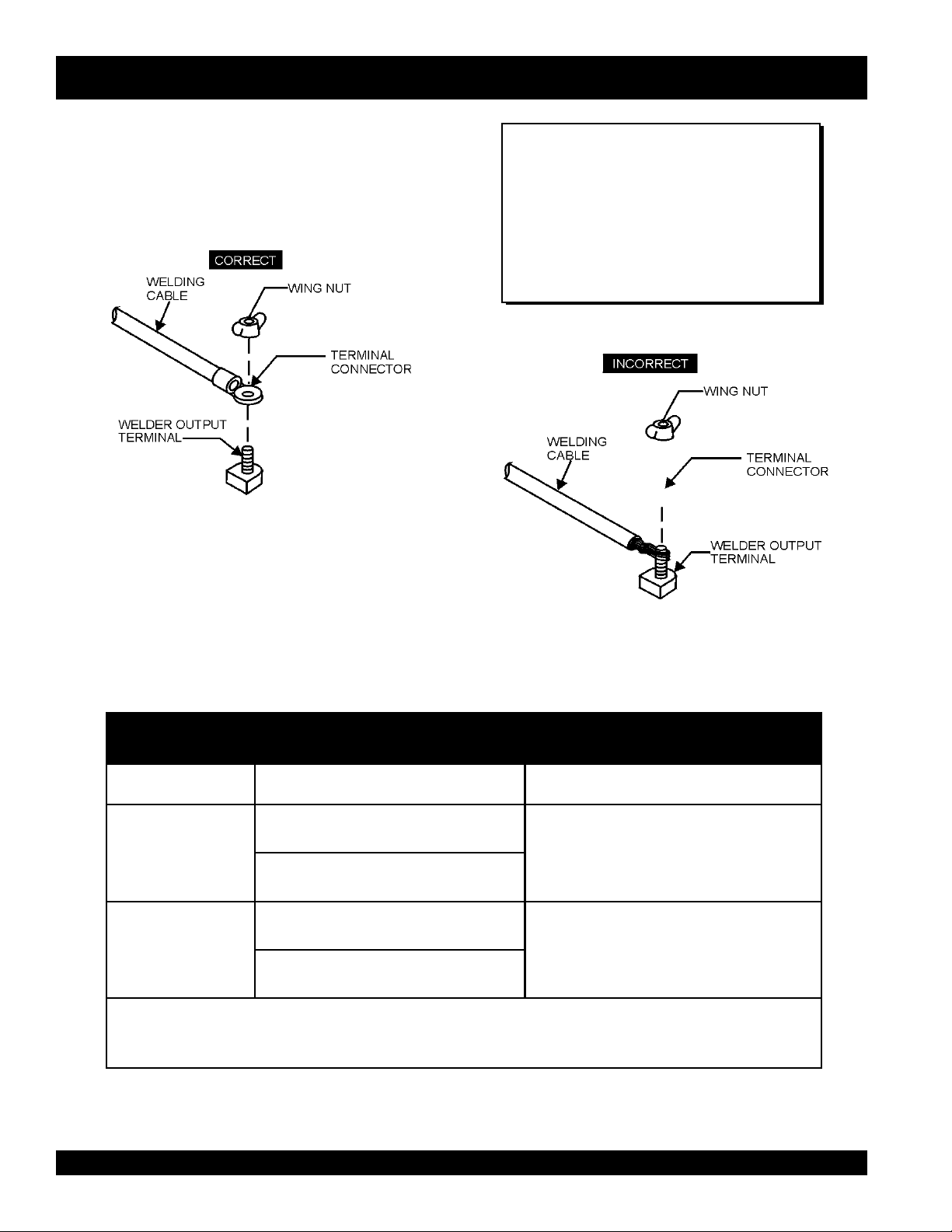
Welding Cables and Polarities
Connect the welding cables (Figure 8) to the welder's output
terminals located on the control panel. The output terminals
have (+) and (-) polarities. Select the appropriate polarities
according to the application (See Welding Applications,
Table 10).
Figure 8. Electrode Cable Connection
(Correct)
NOTE
ALWAYS attach terminal connectors at
the end of each cable. NEVER connect
exposed or frayed wires (Figure 9)
directly to the terminals. Exposed wiring
may cause shocks or di-electric
breakdown from poor contact.
Figure 9. Electrode Cable Connection
YTIRALOPDOHTEMGNIDLEWSNOITACILPPALACIPYT
...
)+(
pmalCdnuorG
ytiraloPthgiartS
redloHedortcelE...)-(
pmalCdnuorG...)+(
ytiraloPesreveR
...
)+(
redloHedortcelE
.rerutcafunameriwehtmorfsnoitcurtsni
(Incorrect)
snoitacilppAgnidleW.01elbaT
larenegrofslairetamleetsgnidleW
.setalpssenkcihtdna,serutcurts
yollareppocrofgnidlewcrA
fognidlewCRA,gnidlewpu-dliuB
setalpniht
leetssselniatsfognidlewcrA
ehtwollof,scitretcarahcVCehtniytiralopehtfonoitcelesehtgnidraugeR:etoN
PAGE 26 —DAW-500S WELDER/A.C. GENERATOR— PARTS & OPERATION MANUAL — REV. #0 (07/19/01)
Page 27
DAW-500S— WELDER OPERATING INSTRUCTIONS
CAUTION :
Never turn Main or Sub Welding CV/CC
Selector Switch while using welder.
CV MODE
This mode is for use of wire feeders. Use the voltage control
to adjust the feeding speed. See Table 11 for maximum
voltage range in relevant to electrode size.
CV HIGH
Adjust the CV Voltage Regulator for welding output voltage,
with Main Welding CV/CC Selector Switch turned to the right
side and the Sub Selector Switch to CV HIGH.
NOTE
The CC Current Regulator will not function in this
position.
CC Mode (for stick)
This mode is for use of welding sticks. Use the current
regulator to adjust the feeding speed. See Table 11 for
maximum current range in relevant to electrode size.
CC HIGH
Adjust the CC Current Regulator for welding current, with
Main Welding DV/CC Selector Switch turned to the right side
and the Sub Welding CV/CC Selector Switch turned to the
lower position .
NOTE
The CV Voltage Regulator will not function in this
position.
CC LOW
Adjust the CC Current Regulator for welding current, with
Main Welding CV/CC Selector Switch turned to the left side.
CV LOW Position
Adjust the CV Voltage Regulator for welding output voltage,
with Main Welding CV/C Selector Switch turned to the right
side and the Sub Selector Switch to the center, CV LOW.
NOTE:
The idle control switch will not function and the engine
will remain on low speed during welding operation in
this mode.
egnaRtnerruC
NOTE
The Sub Selector Switch and CV Voltage
Regulator will not function in this mode.
egnaRtnerruCdnaeziSedortcelE.11elbaT
A052otmuminiM
mumixaMotA002
woLCC
eziSedortcelE23/7ot23/3
hgiHCC
retemaiD61/5ot61/3
retemaiD
DAW-500S WELDER/A.C. GENERATOR — PARTS & OPERATION MANUAL — REV.#0 (07/19/01) — PAGE 27
Page 28

DAW-500S — WELDER/GENERATOR USE
Ground
The nut and ground terminal on the welder/AC generator
should always be used to connect to a suitable ground. The
ground path should be of #8 size wire.
Connect the terminal of the ground wire between the lock
washer and the nut and tighten the nut fully. Connect their
end of the wire to a suitable ground.
htgneLelbaClatoT
gnidleWnideecxEottoN
serepmA
0014#4#4#3#2#0/1#0/1#
0513#2#1#0/1#0/2#0/3#0/3#
0522#1#0/1#0/2#0/3#0/4#0/4#
0031#0/1#0/2#0/3#0/4#0/2-2#0/2-2#
0530/1#0/2#0/3#0/4#0/2-2#0/3-2#0/3-2#
.tf001
ro)m03(
ssel
.tf051
)m54(
.tf002
)m06(
Welding Cable
When welding, use the table below (Table 12) to measure
the optimum amount of voltage and amperes when selecting
the proper welding cable. The relationship between cable
length and sectional area is to keep the line voltage drop
within 4V.
seziSelbaCgnidleW.21elbaT
.tf052
)m07(
.tf003
)m09(
.tf053
)m501(
.tf004
)m031(
0040/2#0/3#0/4#0/2-2#0/3-2#0/3-2#0/4-2#
0050/3#0/4#0/2-2#0/3-2#0/4-2#0/3-3#0/3-3#
Welding and Auxiliary Outputs
In the position of CV Low, the engine will continue run at a
low speed, even if AC load is applied. For this reason, it is
recommended not to use AC output terminal when in this
mode of welding.
The welder can supply a welding current of 120 amps, and
the AC generator can supply up to 3 kW of power at 120
volts simultaneously.
Welding/AC Power
This unit will provide simultaneous use of DC welding power
and AC output power. Use the table below (Table 13) when
selecting electrode size for the amount of AC power
available.
yticapaCrewoPCA/gndleWCD.31elbaT
EZISEDORTCELEGNIDLEWYTICAPACECRUOSREWOPCA
)A08("23/3AVk3
)A031("8/1AVk2.2
)A071("23/5AVk0.2
)A022("61/3AVk7.1
)A072("23/7AVk0.1
"4/1NAHTSSEL0
PAGE 28 —DAW-500S WELDER/A.C. GENERATOR— PARTS & OPERATION MANUAL — REV. #0 (07/19/01)
Page 29
DAW-500S— WELDER/GENERATOR USE
Duty Cycle
The welder is rated at 100% duty cycle at 350 amps. Duty
Cycle refers to the amount of time the user can weld and
how long the machine must rest. The duty cycle depends
upon the welding current being used. Select the appropriate
duty cycle from Table 14 to prevent overload.
EXAMPLE:
The 450 amp, 60% duty cycle referenced in
Table 14 is for CV welding ONLY.
elcyCytuD.41elbaT
)%(elcyCytuD0010806
)spmA(tnerruCsselro053004054
FIVE ESSENTIALS FOR PROPER
WELDING PROCEDURES
Besides the steady sizzling sound that a correct arc
produces, the shape of the molten pool and the movement of the metal at the rear of the pool serve as a guide
in checking weld quality. In a correctly made deposit, the
ripples produced on the bead will be uniform and the bead
will be smooth, with no overlap or undercut.
1. Correct Electrode Size
The correct choice of electrode size involves consideration of a variety of factors. Such as the type, position,
and preparation of the joint, the ability of the electrode to
carry high current values without injury to the weld metal
or loss of deposition efficiency. The mass of work metal
and its ability to maintain its original properties after
welding, the characteristics of the assembly with reference to effect of stresses set up by heat application, the
practicability of heat treatment before and/or after welding,
the specific requirements as to welding quality and the
cost of achieving the desired results.
2. Correct Current
If current on equipment is too high or too low, you are
certain to be disappointed in your weld. If too high, the
electrode melts too fast and your molten pool is large and
irregular. If too low, there is not enough heat to melt the
base metal and your molten pool will be too small, will pile
up, and look irregular.
3. Correct Arc Length
If the arc is too long or voltage too high the metal melts
off the electrode in large globules which wobble from side
to side as the arc wavers, giving a wide, spattered and
irregular bead–with poor fusion between original metal and
deposited metal.
If the arc is too short or voltage too low, there is not
enough heat to melt the base metal properly and the
electrode quite often sticks to the work. This gives a high,
uneven bead, having irregular ripples and poor fusion.
4. Correct Travel Speed
When your speed is too fast: your pool does not last long
enough, impurities and gas is locked in. The bead is
narrow and ripples pointed. When speed is too slow: the
metal piles up, the bead is high and wide, with a rather
straight ripple.
5. Correct Electrode Angle
The electrode angle is of particular importance in fillet
welding and deep groove welding. Generally speaking,
when making a filet weld, the electrode should be held so
that it bisects the angle between the plates and is
perpendicular to the line of weld. If under cut occurs in the
vertical member lowers the angle of the arc and directs
the arc toward the vertical member.
CAUTION :
Always wear welding shield with correct
filter shade when welding. Improper use,
or looking directly at the arc will lead to
blindness.
CAUTION :
Use protective screens or barriers to
protect others from flash and glare; warn
others not to stare at the welding arc.
DAW-500S WELDER/A.C. GENERATOR — PARTS & OPERATION MANUAL — REV.#0 (07/19/01) — PAGE 29
Page 30

DAW-500S — ENGINE OPERATING INSTRUCTIONS
WARNING:
The engine's exhaust contains harmful
emissions. ALWAYS ventilate the
exhaust when operating inside tunnels,
excavations or buildings. Direct exhaust
away from nearby personnel.
Before Starting
1. Disconnect the electrical load and switch the main circuit
breaker to the 'OFF ' position.
2. Check the fuel level on the fuel gauge. If the fuel is low
fill the fuel tank with clean, fresh diesel fuel.
CAUTION:
If any diesel spillage occurs, completely
wipe up the spilled diesel fuel.
3. Check the lubricating oil level. If there is not enough
lubricating oil, fill the crankcase with high grade motor
oil. Use a high quality detergent oil classified CC or
higher (See Table 8 on page 23).
Starting
1. Turn the fuel cock lever to the “ON” position (Figure 10).
Figure 10. Fuel cock lever set to 'ON' position
2. Close doors. Operations with the doors open may cause
insufficient cooling to the unit, and damage may result.
3. Insert the key into the starter switch and turn it to the “RUN”
position. Check to see the oil pressure and charge lights
on the "Warning Lamp Unit " are lit. If either are not lit, check
the system and wiring (refer to the Kubota Engine
Operator's Manual).
4. Turn the key to the 'HEAT' position. When the preheat light
is off, turn the key to the 'START' position to start the engine
(Figure 11). As soon as the engine starts, release the key.
The key will automatically return to the 'ON' position.
4. Check the coolant level in the radiator and subtank.
Replenish with antifreeze as necessary. Always maintain
the coolant level between the FULL and LOW markings
on the coolant container. Be sure the radiator cap is
fastened securely.
Figure 11. Key switch set to 'HEAT'
5. During winter or when the surrounding air temperature is
cold, in situations where a load start is required, turn
the key to the 'HEAT' position, you must wait until the
preheat light goes off.
6. If the engine does not start within 10 seconds after the
key is turned to the 'START' position, wait for about 30
seconds and repeat the procedure as described in
step 4.
CAUTION:
NEVER turn the key to the 'START'
position while the engine is running.
PAGE 30 —DAW-500S WELDER/A.C. GENERATOR— PARTS & OPERATION MANUAL — REV. #0 (07/19/01)
Page 31

DAW-500S — ENGINE OPERATING INSTRUCTIONS
7. When the engine starts, the oil pressure light and charge
light should go out. If these lights stay on, immediately
stop the engine and check the system and wiring (refer to
the Kubota Engine Operator's Manual).
8. Let the engine idle for five minutes with the automatic idle
control switch in the “ON” position.
9. Check the engine for abnormal vibrations, noises and oil
leakage.
10. Check the generator's output voltage by referring to the
DC voltmeter on the control panel.
Shutdown
1. Remove the load from the welder/AC generator, then
place both the main and GFCI circuit breakers to the
"OFF" position.
2. Listen for the engine speed to drop. Run at low speed
for 3-5 minutes.
3. Stop the engine by turning the key to “STOP” position
and remove the key. Turn the fuel cock lever to the
“OFF” position.
DAW-500S WELDER/A.C. GENERATOR — PARTS & OPERATION MANUAL — REV.#0 (07/19/01) — PAGE 31
Page 32

DAW-500S — MAINTENANCE
General Inspection
Prior to each use, the generator should be cleaned and
inspected for deficiencies. Check for loose, missing or
damaged nuts, bolts or other fasteners. Also check for fuel,
oil, and coolant leaks.
Engine Side (Refer to the Engine Instruction Manual)
Service Daily
If the engine is operating in very dusty or dry grass
conditions, a clogged air cleaner will result. This can lead to
a loss of power, excessive carbon buildup in the combustion
chamber in high fuel consumption.
Air Cleaner
Every 100 hours: The air cleaner used on this unit is a dry
type. NEVER apply oil to the air cleaner. If welder/AC
generator has been used in extreme dusty area, service air
cleaner more frequently.
Release the air cleaner retaining clamps (Figure 12) and
remove the air cleaner element.
the drain cock and drain the contents. During cold weather,
the more empty volume inside the tank, the easier it is for
water to condense. This can be reduced by keeping the
tank full as much as possible.
Air Removal
If air enters the fuel injection system of a diesel engine,
starting becomes impossible. After running out of fuel, or
after disassembling the fuel system, bleed the system
according to the following procedure.
To restart after running out of fuel, turn the switch to the
“ON” position for 15-30 seconds. Try again, if needed. This
unit is equipped with an automatic air bleeding system.
Cleaning the Fuel Strainer
Clean the fuel mesh strainer located under fuel capif it
contains dust or water. Remove dust or water in the strainer
cap and wash it in gasoline. Securely fasten the fuel strainer
cap so that fuel will not leak. Check the fuel strainer every
200 hours of operation or once a month. If damaged, replace
with P/N 1552143160.
Check Oil Level
Figure 12. Air Cleaner Element
Wipe the inside of the air cleaner with a damp cloth and
remove all dust and debris that have accumulated inside
the air cleaner body.
Used compressed air to clean air filter element. DO NOT
use more than 99 psi. Blow compressed air from the inside
while turning the element.
If damaged, replace with P/N 7000011081.
Fuel Addition
Add diesel fuel (the grade may vary according to season
and locations). Always pour through the mesh filter.
Removing Condensation from the Fuel Tank
After prolonged use, condensation and other impurities
accumulate in the bottom of the tank. Occasionally remove
Check the crankcase oil level prior to each use, or when the
fuel tank is filled. Insufficient oil may cause severe damage
to the engine. Make sure the generator is level. The oil level
must be between the two notches on the dipstick as shown
in Figure 31, page 39.
Replacing Oil Filter
! Drain oil from engine. Use recyclable container to hold
used oil. Replace cartridge with P/N 700032091.
! Detach the oil filter cartridge with a filter wrench.
! Apply a film of oil to the gasket for the cartridge.
! Screw in the cartridge by hand. When the gasket is in
contact with the seal surface, tighten the cartridge one
or two more times by hand.
! After the oil cartridge has been replaced, add oil
according to recommended motor oil (Table 6, page 22).
Run the engine for a while and check for leaks before
adding more oil if needed. Clean excessive oil from
engine.
Replacing Fuel Filter
! Replace the fuel filter cartridge with new one every 200
hours or so. Use P/N 1707643010.
PAGE 32 —DAW-500S WELDER/A.C. GENERATOR— PARTS & OPERATION MANUAL — REV. #0 (07/19/01)
Page 33

DAW-500S — MAINTENANCE
! Apply fuel oil thinly over the gasket and hand-tighten
the cartridge into position.
! Vent any air.
Flushing Out Radiator and Replacing Coolant
! Open both cocks located at the crankcase side and at
the lower part of the radiator and drain coolant. Open
the radiator cap while draining. Remove the overflow
tank and drain.
! Check hoses for softening and kinks. Check clamps
for signs of leakage.
! Flush the radiator by running clean tap water through
radiator until signs of rust and dirt are removed. DO
NOT clean radiator core with any objects, such as a
screwdriver.
! Tighten both cocks and replace the overflow tank.
! Replace with coolant (see page 40, Table 12 for mixture).
! Close radiator cap tightly.
CAUTION :
Allow engine to cool when flushing out
radiator. Flushing the radiator while hot
will damage engine and radiator.
Generator Storage
For storage of the generator for over 30 days, the following
is required:
! Drain the fuel tank completely.
! Completely drain the oil from the crankcase and refill
with fresh oil.
! Clean all external parts of the generator with a cloth.
! Cover the generating set and store in a clean, dry place.
! Disconnect eh battery cable (+) (-) from battery.
ECNANETNIAM/NOITCEPSNI
sleveLdiulFenignEkcehC X
renaelCriAkcehC X
leveLdicAyrettaBkcehC X
noitidnoCtleBnaFkcehC X
skaeLrofkcehC X
straPfogninesooLrofkcehC X
*liOenignEecalpeR X X
*retliFliOecalpeR X
ENIGNE
ROTARENEG
retliFriAnaelC X
knaTleuFfomottoBniarD X
edistuOdnaedisnI,tinUnaelC X
*retliFleuFegnahC X
leveLnoitcetorPtnalooCkcehCdnarotaidaRnaelC X
tnemelEretliFriAecalpeR
spmalCdnasesoHllakcehC
knaTleuFfoedisnInaelC
smhoM3revOecnatsiseRnoitalusnIerusaeM X
YLIADsrH01 .srH001 srH002 srH004 srH005
srH0001
X
X
X
.gninnurfosruoh05laitiniretfaretlifliodna,retlifleuf,lioecalpeR*
DAW-500S WELDER/A.C. GENERATOR — PARTS & OPERATION MANUAL — REV.#0 (07/19/01) — PAGE 33
Page 34

DAW-500S —GENERATOR WIRING DIAGRAM
PAGE 34 —DAW-500S WELDER/A.C. GENERATOR— PARTS & OPERATION MANUAL — REV. #0 (07/19/01)
Page 35

DAW-500S —ENGINE WIRING DIAGRAM
DAW-500S WELDER/A.C. GENERATOR — PARTS & OPERATION MANUAL — REV.#0 (07/19/01) — PAGE 35
Page 36

DAW-500S — TROUBLESHOOTING (WELDER)
Practically all breakdowns can be prevented by proper
handling and maintenance inspections, but in the event of a
breakdown, please take a remedial action following the
MOTPMYS MELBORPELBISSOP NOITULOS
?deepswoL .noitces"deepswoltasniamerenignE"otrefeR
?)R(rotsiserevitcefeD .rotsiserecalpeR
s'rotarenegnitneserptonsiegatlovCA
.noitcesgnidlewronoitcesCA
CAniegatlovwoldnagnidlewrooP
.noitcesrewop
?rotorevitcefeD .rotorecalpeR
?3FesufnwolB .esufecalpeR
?rotorevitcefeD .rotorecalpeR
?deepswoL .noitces"deepswoltasniamerenignE"otrefeR
?gnidniw
?rellortnoCdleiFevitcefeD ."rellortnoCdleiF"ecalpeR
?gniriWevitcefeD .gniriwriapeR
?rellortnoCdleiFevitcefeD ."rellortnoCdleiF"ecalpeR
erutamranitiucric-trohsreyaL
diagnosis based on the Welder Troubleshooting (Table 15)
information shown below . If the problem cannot be remedied,
please leave the unit just as it is and consult our company's
business office or service plant.
GNITOOHSELBUORTREDLEW.51ELBAT
.erutamraecalpeR
?gniriwevitcefeD .gniriwriapeR
?rellortnoCdleiFevitcefeD ."rellortnoCdleiF"ecalpeR
?)eR(reifitcerevitcefeD .reifitcerecalpeR
onsierehttubtublamronsirewopCA
egatlovdnatnerruC.ytilibapacgnidlew
.evitarepo-nierastnemtsujda
,desuebtonnacrowolootsirewopCA
.lamronsignidlewtub
.noosootsegrahcsidyrettaB `?rotalugerenigneevitcefeD .rotalugerecalpeR
?elbacgnidlew
?gnidniw
?gniriwevitcefeD .gniriwriapeR
?sehctiwsrotcelesevitcefeD .2Sro1SecalpeR
?rekaerbtiucricevitcefeD .rekaerbtiucricecalpeR
?)edisCA(
?gniriwevitcefeD .gniriwriapeR
?rellortnoCdleiFevitcefeD ."rellortnoCdleiF"ecalpeR
?remrofsnarttnerrucevitcefeD .3TCro2TC,1TC,remrofsnartecalpeR
?)2Lro1LroLCD(rotcaerevitcefeD .rotcaerecalpeR
fossenkcihtdnahtgneletauqedanI
erutamranitiucric-trohsreyaL
gnidniwerutamranitiucric-trohsreyaL
.elbacgnidlewecalpeR
.erutamraecalpeR
.erutamraecalpeR
?gniriwevitcefeD .gniriwriapeR
?hctiwsnoitingievitcefeD .hctiwsnoitingiecalpeR
PAGE 36 —DAW-500S WELDER/A.C. GENERATOR— PARTS & OPERATION MANUAL — REV. #0 (07/19/01)
Page 37

DAW-500S — TROUBLESHOOTING (ENGINE)
Practically all breakdowns can be prevented by proper
handling and maintenance inspections, but in the event of a
breakdown, please take a remedial action following the
MOTPMYS MELBORPELBISSOP NOITULOS
?leufoN .leufhsinelpeR
?metsysleufehtniriA .metsysdeelB
?metsysleufehtniretaW .knatleufmorfretawevomeR
?deggolcepipleuF .epipleufnaelC
?deggolcretlifleuF .retlifleufegnahcronaelC
ytisocsivhgihylevissecxE
woltalioenigneroleuffo
?erutarepmet
diagnosis based on the Engine and Generator Troubleshooting
(Table 16) information shown below and on the proceeding
page. If the problem cannot be remedied, please leave the
unit just as it is and consult our company's business office
or service plant.
)1TRAP(GNITOOHSELBUORTENIGNE.61ELBAT
.lioenigneroleufdeificepsehtesU
enatecwolhtiwleuF
?rebmun
esooloteudkaelleuF
?tungniniaterepipnoitcejni
.tratstonseodenignE
pmupnoitcejnI
?gninoitcnuflam
?gniraebrorenil
?rednilyc
?gnimitnoitcejnitcerrocnI .tsujdA
?nrowtfahsmacleuF .ecalpeR
?deggolcelzzonnoitcejnI .elzzonnoitcejninaelC
,tfahsknarcfoeruzieS
rednilyc,notsip,tfahsmac
morfkaelnoisserpmoC
?gnimitevlavreporpmI .raeggnimitecalperrotcerroC
?nrowrenildnagnirnotsiP .ecalpeR
.tunnethgiT
.leufdeificepsehtesU
.ecalperroriapeR
.ecalperroriapeR
wolg,tlobdaehrednilycnethgit,teksagdaehecalpeR
.redlohelzzondnagulp
?ecnaraelcevlavevissecxE .tsujdA
DAW-500S WELDER/A.C. GENERATOR — PARTS & OPERATION MANUAL — REV.#0 (07/19/01) — PAGE 37
Page 38

DAW-500S — TROUBLESHOOTING (ENGINE)
MOTPMYS MELBORPELBISSOP NOITULOS
?ytridrodeggolcretlifleuF .egnahcronaelC
?deggolcrenaelcriA .egnahcronaelC
)2TRAP(GNITOOHSELBUORTENIGNE.61ELBAT
esooloteudkaelleuF
?tungniniaterepipnoitcejni
pmupnoitcejnI
?gninoitcnuflam
.htooms
tonsinoituloverenignE
?erusserp
?deggolc
?deggolc
eulbroetihwrehtiE
.devresbosisagtsuahxe
?kcutsro
gninepoelzzontcerrocnI
rokcutselzzonnoitcejnI
epipwolfrevoleuF
?gninoitcnuflamronrevoG .riapeR
?lioenigneevissecxE .leveldeificepsehtotecudeR
nrowrenildnagnirnotsiP
?gnimitnoitcejnitcerrocnI .tsujdA
?noisserpmoctneicifeD .ecnaraelcpottsujdA
.tunnethgiT
.ecalperroriapeR
.tsujdA
.ecalperroriapeR
.naelC
.ecalperroriapeR
?daolrevO .daolehtnesseL
?desuleufedargwoL .leufdeificepsehtesU
yargkradrokcalbrehtiE
.devresbosisagtsuahxe
.tuptuotneicifeD
PAGE 38 —DAW-500S WELDER/A.C. GENERATOR— PARTS & OPERATION MANUAL — REV. #0 (07/19/01)
?deggolcretlifleuF .egnahcronaelC
?deggolcrenaelcriA .egnahcronaelC
?noitcejnielzzontneicifeD .elzzonehtecalperroriapeR
?gnimitnoitcejnitcerrocnI .tsujdA
strapgnivoms'enignE
?gniziesebotmees
?noitcejnileufnevenU .pmupnoitcejniehtecalperroriapeR
?noitcejnielzzontneicifeD .elzzonehtecalperroriapeR
?kaelnoisserpmoC
.ecalperroriapeR
wolg,tlobdaehrednilycnethgit,teksagdaehecalpeR
.redlohelzzondnagulp
Page 39

DAW-500S — TROUBLESHOOTING (ENGINE)
MOTPMYSMELBORPELBISSOPNOITULOS
?tiucrictaeh-erpnekorB.tiucrictaeh-erpkcehC
retratsdnatratsotsliafenignE
.setator
woltasniamerdnastratsenignE
.deeps
.nurtonseodretratS ?degrahcsidyrettaB .yrettabegrahC
?leufoN.leufddA
?gniriwevitcefeD.gniriwkcehC
?reniartsleufdeggolC.ecalperronaelC
?renaelcriadeggolC.ecalperronaelC
?gniriwdetcennocsiD.gniriwriaperdnakcehC
?gninoitcnuflamretratS .ecalperroriapeR
?gninoitcnuflamhctiwsyeK .ecalperroriapeR
?detcennocsidgniriW .gniriwtcennoC
?tuodenrub5FesuF.esufecalpeR
)3TRAP(GNITOOHSELBUORTENIGNE.61ELBAT
rewopCAnitneserpegatlovoN
?ecruos
?rotorevitcefeD.rotorecalpeR
egatlovondnasesirdeepsenignE
.ecruosrewopCAnitneserpsi
?gnidniw
rewopCAdnasesirdeepsenignE
ebtonnacrowolootsiegatlov
.desu
enignednasesirdeepsenignE
.dedaolrevosmees
lortnoCeldI"dnastratsenignE
enignE.noitisopFFOnisi"hctiwS
egralsahenignednasesirdeeps
.sdaolrevO.snoitarbiv
lortnoCeldI"dnastratsenignE
enignE.noitisopFFOnisi"hctiwS
sahenignednasesirdeeps
.esionlamronba
?retemtlovevitcefeD.retemtlovecalpeR
?gniriwdetcennocsiD.gniriwriaperdnakcehC
erutamranitiucric-trohsreyaL
?)rotcetorp(rekaerbtiucricevitcefeD .)rotcetorp(rekaerbtiucricecalpeR
niseriwnekorb,tiucric-trohsreyaL
?gnidniwerutamra
?rotanretlaevitcefeD.rotanretlaecalperroriapeR
?gniraebrotanretladegamaD.sgniraebrotanretlaecalpeR
?noitallatsnienignedaB.enignefonoitallatsnitaepeR
?strapenigneesooL .senthgitrofstrapenignellakcehC
?rotanretlaevitcefeD esoolrogniraebdegamadrofrotanretlakcehC
.stlobgnipmalc
.)1ER(reifitcerecalpeR
.erutamraecalpeR
.erutamraecalperroriapeR
?erusolcneevitcefeD .ssenthgitrofstloberusolcnekcehC
lortnoCeldI"dnastratsenignE
enignE.noitisopFFOnisi"hctiwS
hgihtasniamerdnasesirdeeps
sihctiwslortnoCeldInehwdeeps
.noitisopNOehtnidecalp
?dionelosevitcefeD .dionelosecalpeR
?yalerevitcefeD .yalerecalpeR
?ecivedlortnoceldievitcefeD .ecivedlortnoceldiecalperroriapeR
?hctiwslortnoceldievitcefeD .hctiwslortnoceldiecalpeR
DAW-500S WELDER/A.C. GENERATOR — PARTS & OPERATION MANUAL — REV.#0 (07/19/01) — PAGE 39
Page 40

EXPLANATION OF CODE IN REMARKS COLUMN
How to read the marks and remarks used in this parts
book.
Items Found In the “Remarks” Column
Serial Numbers-Where indicated, this indicates a serial
number range (inclusive) where a particular part is used.
Model Number-Where indicated, this shows that the
corresponding part is utilized only with this specific model
number or model number variant.
Items Found In the “Items Number” Column
All parts with same symbol in the number column, *, #, +,
%, or ■, belong to the same assembly or kit.
Note: If more than one of the same reference number is
listed, the last one listed indicates newest (or latest) part
available.
NOTE
The contents of this parts catalog are
subject to change without notice.
PAGE 40 —DAW-500S WELDER/A.C. GENERATOR— PARTS & OPERATION MANUAL — REV. #0 (07/19/01)
Page 41

DAW-500S — SUGGESTED SPARE PARTS
DAW-500S W/KUBOTA D1703-EB DIESEL
ENGINE 1 TO 3 UNITS
Qty. P/N Description
5 ............ 7000011081 .......... AIR FILTER
5 ............ 1552143160 .......... FUEL FILTER
5 ............ 7000032091 .......... OIL FILTER
2 ............ 1711297010 .......... FAN BELT
1 ............ 3741059110 .......... STARTER SWITCH
5 ............ 3741055151 .......... IGNITION KEY
2 ............ 1584139010 .......... OIL SENDING UNIT
1 ............ D6312500803 ....... RADIATOR HOSE (UPPER)
1 ............ D6312500713 ....... RADIATOR HOSE (LOWER)
1 ............ 0810105900 .......... FUEL CAP
1 ............ 0602200467 .......... EMERGENCY UNIT
1 ............ 0601842464.......... RESISTOR
1 ............ 0601807454 .......... MAIN CIRCUIT BREAKER
1 ............ 1982639003 .......... SOLENOID, ROTARY
4 ............ 1907765510 .......... GLOW PLUG
2 ............ 1554383040 .......... SWITCH, WATER TEMP.
1 ............ 0602201378 .......... REGULATOR
2 ............ 0601821391 .......... RECTIFIER
1 ............ 0601803071 .......... CV/CC SELECTOR SWITCH
2 ............ D1233000004 ....... OUTPUT TERMINAL
2 ............ 0801880004 .......... INSULATOR WASHER
4 ............ 0039510000 .......... HEX NUT
4 ............ 0045110000 .......... LOCK WASHER
4 ............ 0042710000.......... PLAIN WASHER
2 ............ 0000000002 .......... WING NUT
1 ............ D9925800104 ....... CONTROL UNIT
1 ............ D9925800184 ....... CONTROL UNIT
DAW-500S WELDER/A.C. GENERATOR — PARTS & OPERATION MANUAL — REV.#0 (07/19/01) — PAGE 41
Page 42

GENERATOR ASSY.
DAW-500S — GENERATOR ASSY.
PAGE 42 —DAW-500S WELDER/A.C. GENERATOR— PARTS & OPERATION MANUAL — REV. #0 (07/19/01)
Page 43

DAW-500S — GENERATOR ASSY.
GENERATOR ASSY.
NO PART NO PART NAME QTY. REMARKS
1 D6110000202 ROTOR ASSY. 1
2 0340010045 HEX. HEAD BOLT 6
3 030210250 LOCK WASHER .......................... 6 .............. REPLACES 0042510000
4 D6130200103 STATOR ASSY. 1
5 0012110120 HEX. HEAD BOLT 6
6 030210250 LOCK WASHER .......................... 6 .............. REPLACES 0042510000
7 031110160 PLAIN WASHER .........................6 .............. REPLACES 0041210000
8 D6153400102 COVER 1
9 D6153300113 GROMMET 2
DAW-500S WELDER/A.C. GENERATOR — PARTS & OPERATION MANUAL — REV.#0 (07/19/01) — PAGE 43
Page 44

CONTROL PANEL ASSY.
DAW-500S — CONTROL PANEL ASSY.
PAGE 44 —DAW-500S WELDER/A.C. GENERATOR— PARTS & OPERATION MANUAL — REV. #0 (07/19/01)
Page 45

DAW-500S — CONTROL PANEL ASSY.
CONTROL PANEL ASSY.
NO PART NO PART NAME QTY. REMARKS
1 D6225000603 CONTROL PANEL 1
2 0021806030 MACHINE SCREW 5
3 0601803071 WELDING MAIN SELECTOR ........................... 1 ............ SK2533MS
4 8705945004 SEAL 1
5 0016906016 HEX. HEAD BOLT 3
6 0601830704 WELDING SUB SELECTOR ............................. 1 ............ S7B
7 0601840214 RHEOSTAT (CURRENT AND VOLT. REG.) ....... 2 ............ RV24YN20SB5025KOHM
8 0601840103 KNOB 2
9 0023304008 SET SCREW 2
10 0601800387 DC VOLTMETER............................................... 1 ............ DCF50~100V
11 0601800179 DC AMMETER.................................................. 1 ............ DCF50~750A/6mA
12 0602103098 PILOT OPERATING LAMP 1
0601810248 BULB 1
13 0601807454 CIRCUIT BREAKER ......................................... 1 ............ KM51B25A
14 3011816004 CIRCUIT BREAKER BAND SET ...................... 1 ............ S1B
15 0027404010 MACHINE SCREW 2
16 0601830771 IDLE CONTROL SWITCH 1
17 3741059110 STARTER SWITCH........................................... 1 ............ REPLACES 0602100059
18 0601810523 INDICATOR ASSY. 1
0601810830 BULB 4
19 0602125055 FUEL GAUGE 1
20 0601800682 HOUR METER 1
21 D6235400014 SET BOARD, OUTPUT TERMINAL 1
22 D6235100004 OUTPUT TERMINAL, WELDING 2
23 000000000 2 WING NUT ........................................................ 4 ............ REPLACES 0801884004
24 0039312000 HEX. NUT ......................................................... 4 ............ REPLACES 0039512000
25 0040012000 LOCK WASHER 4
26 0041412000 PLAIN WASHER 8
27 D6235500214 RUBBER SEAL 1
28 0021106020 MACHINE SCREW 1
29 0601825115 SURGE FILTER 1
30 0601811031 RECEPTACLE................................................... 1 ............ REPLACES 0601811035
31 0601812597 RECEPTACLE................................................... 1 ............ REPLACES 0601812598
32 0601826150 CONDENSER 1
33 0027404015 MACHINE SCREW 4
0038704000 HEX. NUT 4
34 0601806420 CIRCUIT PROTECTOR 1
35 0021003005 MACHINE SCREW 2
36 0601815109 GROUND TERMINAL 1
37 D6238100514 COVER, OUTPUT TERMINAL 1
38 D6238400404 RUBBER SEAL 2
39 0805088004 STAY RUBBER 2
40 011206020 HEX. HEAD BOLT ............................................. 1 ............ REPLACES 0017106020
0017106000 HEX. NUT 1
41 011206020 HEX. HEAD BOLT ............................................. 1 ............ REPLACES 0017106020
42 0017106016 HEX. HEAD BOLT 1
DAW-500S WELDER/A.C. GENERATOR — PARTS & OPERATION MANUAL — REV.#0 (07/19/01) — PAGE 45
Page 46

ELECTRIC PARTS (1) ASSY.
DAW-500S — ELECTRIC PARTS (1) ASSY.
PAGE 46 —DAW-500S WELDER/A.C. GENERATOR— PARTS & OPERATION MANUAL — REV. #0 (07/19/01)
Page 47

DAW-500S — ELECTRIC PARTS (1) ASSY.
ELECTRIC PARTS (1) ASSY.
NO PART NO PART NAME QTY. REMARKS
1 D6353600133 SET PANEL, ELEC. PARTS ...... 1
2 0017406016 HEX.HEAD BOLT 4
3 0601842464 RESISTOR 1
4 0027104016 MACHINE SCREW 2
5 0601827619 RELAY ...................................... 1 ........... G7L2ABUBDC12V
6 0027104016 MACHINE SCREW 2
7 0601821391 RECTIFIER ............................... 1 ........... DF100BA40; REPLACES 0601821359
8 0027105016 MACHINE SCREW 2
9 8701899004 FUSE BOX ................................ 1 ........... FB6PS
0601806642 FUSE, 5A 4
0601806643 FUSE, 15A 2
0601806644 FUSE, 30A 2
10 0027105020 MACHINE SCREW 2
11 0602200467 EMERGENCY UNIT.................. 1 ........... 1746260601
12 0027106025 MACHINE SCREW 4
13 1569465990 LAMP TIMER ............................ 1 ........... REPLACES 0602201273 AND1569465992
14 0027105016 MACHINE SCREW 1
15 0601823707 RELAY ...................................... 1 ........... ACA3213CA1DC12VN;
REPLACES 0601824527
16 0027105016 MACHINE SCREW 1
17 0601824525 RELAY ...................................... 1 ........... ACA22136CAIBDC12VN
18 0027105016 MACHINE SCREW 1
19 0601815759 TERMINAL BOARD .................. 1 ........... KT206P
D9522000104 DECAL; SYMBOL MARK 1
20 0027105025 MACHINE SCREW 2
21 0601823204 RECTIFIER ............................... 1 ........... S5VB60
22 0027103016 MACHINE SCREW 1
23 0601806640 FUSE, 65A 1
DAW-500S WELDER/A.C. GENERATOR — PARTS & OPERATION MANUAL — REV.#0 (07/19/01) — PAGE 47
Page 48

ELECTRIC PARTS (2) ASSY.
DAW-500S — ELECTRIC PARTS (2) ASSY.
PAGE 48 —DAW-500S WELDER/A.C. GENERATOR— PARTS & OPERATION MANUAL — REV. #0 (07/19/01)
Page 49

DAW-500S — ELECTRIC PARTS (2) ASSY.
ELECTRIC PARTS (2) ASSY.
NO PART NO PART NAME QTY. REMARKS
1 D6215000413 BOX, ELECT. PARTS ................. 1 ......... UP TO S/N5428475
D6215000423 BOX, ELECT. PARTS .................1 ......... S/N5428476~
2 D9925800104 DC CONTROL UNIT ASSY. ....... 1 ......... CA50
3 D9925800184 AC CONTROL UNIT ASSY. ....... 1 ......... CA41
4 0221900245 RUBBER SEAL 1
5 011206020 HEX. HEAD BOLT ...................... 8 ......... REPLACES 0016906020
6 D6215400214 COVER ...................................... 1 ......... UP TO S/N5428475
D4515400224 COVER ...................................... 1 ......... S/N5428476~
7 0017106016 HEX. HEAD BOLT 4
8 0017106016 HEX. HEAD BOLT 6
9 D6485400504 AIR DUCT 1
10 0017106016 HEX. HEAD BOLT 4
11 D6485500303 BRACKET 1
12 0017106016 HEX. HEAD BOLT 5
13 D6265500303 DC REACTOR ............................ 1 ......... L2
14 D6265500403 AC REACTOR ............................ 1 ......... L3
15 0017106016 HEX. HEAD BOLT 8
16 D6262700614 COVER 1
17 0017106016 HEX. HEAD BOLT 4
18 D6262600204 BRACKET, ROT. SOLENOID 1
19 011008020 HEX. HEAD BOLT...................... 2 ......... REPLACES 0017108020
20 1982639003 ROTARY SOLENOID .................. 1 ......... REPLACES 1790150203
21 D6388100104 ARM SOLENOID 1
22 011606025 HEX. HEAD BOLT...................... 1 ......... REPLACES 0010106025
020106050 HEX. NUT .................................. 1 ......... REPLACES 0030006000
23 0050403020 SPRING PIN 1
24 0207006000 HEX. NUT 1
25 D6356300104 GOVERNOR ROD 1
26 8702151004 GOVERNOR ROD 1
27 1552154004 SCREW JOIINT 1
28 0031008000 HEX. NUT 1
29 0039308000 HEX. NUT .................................. 1 ......... REPLACES 0036508000
30 031108160 PLAIN WASHER ........................ 1 ......... REPLACES 0041208000
0605010503 SNAP PIN 1
31 952404470 PLAIN WASHER ........................ 1 ......... REPLACES 0041206000
505015300 SNAP PIN .................................. 1 ......... REPLACES 0605010502
32 8511864601A PLATE ........................................ 1 ......... REPLACES 8511864604
33 0017106016 HEX. HEAD BOLT 5
DAW-500S WELDER/A.C. GENERATOR — PARTS & OPERATION MANUAL — REV.#0 (07/19/01) — PAGE 49
Page 50

ENGINE & RADIATOR ASSY.
DAW-500S — ENGINE & RADIATOR ASSY.
PAGE 50 —DAW-500S WELDER/A.C. GENERATOR— PARTS & OPERATION MANUAL — REV. #0 (07/19/01)
Page 51

DAW-500S — ENGINE & RADIATOR ASSY.
ENGINE & RADIATOR ASSY.
NO PART NO PART NAME QTY. REMARKS
1 D692520034 ENGINE ........................................ 1 ............ KUBOTA D1703
1-1 7000032091 CARTRIDGE, OIL FILTER ........... 1 ............ REPLACES 0602041173
2 D6305200104 ENGINE FOOT 1
3 D6305200004 ENGINE FOOT 1
4 D6133100104 ENGINE FOOT 1
5 D6133100004 ENGINE FOOT 1
6 012212025 HEX. HEAD BOLT ......................... 7 ............ REPLACES 0012412025
7 0012410025 HEX. HEAD BOLT 9
8 7605419004A RUBBER SUSPENSION .............. 2 ............ REPLACES 7605419004
9 7725419004 RUBBER SUSPENSION 2
10 0207010000 HEX. HEAD BOLT 4
11 0602012730 RADIATOR.................................... 1 ............ 4324221318920
0602011064 RADIDATOR CAP 1
12 D6312100624 BRACKET, RADIATOR 1
13 0017106016 HEX. HEAD BOLT 2
14 D6312600304 RUBBER MOUNT 2
15 D6312200213 FAN GUARD 1
16 0017106016 HEX. HEAD BOLT 5
17 D6312500803 RADIATOR HOSE 1
18 D6312500713 RADIATOR HOSE 1
19 0605515134 HOSE BAND 2
20 0605515016 HOSE BAND 2
21 0602046262 AIR CLEANER .............................. 1 ............ IK3111T012
7000011081 ELEMENT, AIR CLEANER ........... 1 ............ REPLACES 1540111081 AND 0602046372
22 1538111250 BAND, AIR CLEANER .................. 1 ............ REPLACES 0602040573
23 011208025 HEX. HEAD BOLT ......................... 1 ............ REPLACES 0017108025
24 D6485500214 BRACKET, AIR CLEANER ........... 1 ............ UP TO S/N5421717
D6485500224 BRACKET, AIR CLEANER ........... 1 ............ S/N5421718~
25 011008020 HEX. HEAD BOLT 2 ............REPLACES 0017108020
26 0017106016 HEX. HEAD BOLT 2
27 D6375100613 HOSE, AIR CLEANER .................. 1 ............ UP TO S/N5421717
D6375100623 HOSE, AIR CLEANER .................. 1 ............ S/N5421718~
28 D6375100714 HOSE, AIR CLEANER .................. 1 ............ UP TO S/N5421717
D6375100724 HOSE, AIR CLEANER .................. 1 ............ S/N5421718~
29 0605515027 HOSE BAND 1
30 0605515001 HOSE BAND 2
31 1502025004 DRAIN JOINT 1
32 0602021193 PACKING 1
33 1502025103C DRAIN JOINT ............................... 1 ............ REPLACES 1502025103
34 0802011104 PLUG 2
35 0150000018 O RING 2
36 0017106016 HEX. HEAD BOLT 4
37 0192200550 DRAIN HOSE 1
38 0605515158 HOSE BAND 2
39 1622014103 DRAIN JOINT 1
40 0199900700 DRAIN HOSE 1
41 0199900600 DRAIN HOSE 1
42 0605515094 HOSE BAND 4
43 0802081403 RESERVE TANK 1
44 0802081104 CAP, RESERVE TANK 1
45 0199100215 HOSE 1
46 8702082004 BRACKET, RESERVE TANK 1
47 011606025 HEX. HEAD BOLT ......................... 1 ............ REPLACES 0017106025
48 0017106016 HEX. HEAD BOLT 2
49 0199900500 HOSE 1
50 0605515094 HOSE BAND 2
DAW-500S WELDER/A.C. GENERATOR — PARTS & OPERATION MANUAL — REV.#0 (07/19/01) — PAGE 51
Page 52

BATTERY ASSY.
DAW-500S — BATTERY ASSY.
PAGE 52 —DAW-500S WELDER/A.C. GENERATOR— PARTS & OPERATION MANUAL — REV. #0 (07/19/01)
Page 53

DAW-500S — BATTERY ASSY.
BATTERY ASSY.
NO PART NO PART NAME QTY. REMARKS
1 0167306531 BATTERY .................................... 1 ........ 65D31R
2 7612251004 BATTERY SHEET 1
3 D6345200004 BATTERY BAND 1
4 1742251004 BATTERY BOLT 2
5 0037806000 WING NUT 2
6 0040006000 LOCK WASHER 2
7 952404470 PLAIN WASHER ......................... 2 ........ REPLACES 0041206000
8 0602220310 TERMINAL ASSY. ...................... 1 ........ NO 9P
9 0602220311 TERMINAL ASSY. ...................... 1 ........ NO. 9N
10 2845040414 TERMINAL CAP ......................... 1 ........ TC7R; REPLACES 0602220600
DAW-500S WELDER/A.C. GENERATOR — PARTS & OPERATION MANUAL — REV.#0 (07/19/01) — PAGE 53
Page 54

MUFFLER ASSY.
DAW-500S — MUFFLER ASSY.
PAGE 54 —DAW-500S WELDER/A.C. GENERATOR— PARTS & OPERATION MANUAL — REV. #0 (07/19/01)
Page 55

DAW-500S — MUFFLER ASSY.
MUFFLER ASSY.
NO PART NO PART NAME QTY. REMARKS
1 D6332000322 MUFFLER 1
2 0017108020 HEX. HEAD BOLT 4
3 D6335000523 EXHAUST PIPE 1
4 1526312370 GASKET .................................... 1 ......... REPLACES 0602320153
5 1502336004 GASKET 1
6 0207008000 HEX. NUT 4
7 0017108035 HEX. HEAD BOLT 2
8 0130012000 ELBOW JOINT 1
DAW-500S WELDER/A.C. GENERATOR — PARTS & OPERATION MANUAL — REV.#0 (07/19/01) — PAGE 55
Page 56

FUEL TANK ASSY.
DAW-500S — FUEL TANK ASSY.
PAGE 56 —DAW-500S WELDER/A.C. GENERATOR— PARTS & OPERATION MANUAL — REV. #0 (07/19/01)
Page 57

DAW-500S — FUEL TANK ASSY.
FUEL TANK ASSY.
NO PART NO PART NAME QTY. REMARKS
1 B6365000423 FUEL TANK 1
1-1 0810105900 CAP, FUEL TANK ....................... 1 ......... REPLACES 0810105800
2 E1924300164 SENDER, FUEL GAUGE 1
3 0022905015 MACHINE SCREW 5
4 D6365300613 BRACKET, FUEL TANK 1
5 0017108020 HEX. HEAD BOLT 4
6 1555527004 TANK SHEET 2
7 D6492700104 RUBBER SEAL 1
8 D6365200104 TANK BAND 2
9 D6365300504 PAD, TANK BAND 4
10 0017106016 HEX. HEAD BOLT 2
11 0207208000 HEX. NUT 2
12 1615511204 RUBBER SEAL 1
13 7812014003 DRAIN JOINT 1
14 0802011104 PLUG 1
15 0150000018 O RING ...................................... 2 ......... AP18
16 0017106016 HEX. HEAD BOLT 2
17 0199900750 DRAIN HOSE 1
18 0605515094 HOSE BAND 2
19 1707643010 FUEL FILTER............................. 1 ......... REPLACES 0602042077
1552143160 ELEMENT, FUEL FILTER .......... 1 ......... REPLACES 0602042174
20 0017108035 HEX. HEAD BOLT 2
21 0605513152 SUCTION HOSE........................ 1 ......... 0966180300
22 0966180180 SUCTION HOSE........................ 1 ......... REPLACES 0605513116
23 0605514064 RETURN HOSE ......................... 1 ......... 0966140280
24 0605514022 RETURN HOSE ......................... 1 ......... 0966140170
25 0605515179 HOSE BAND .............................. 4 ......... 1430142753
26 1024442320 HOSE BAND .............................. 4 ......... REPLACES 0605515072
DAW-500S WELDER/A.C. GENERATOR — PARTS & OPERATION MANUAL — REV.#0 (07/19/01) — PAGE 57
Page 58

ENCLOSURE ASSY
DAW-500S — ENCLOSURE ASSY.
PAGE 58 —DAW-500S WELDER/A.C. GENERATOR— PARTS & OPERATION MANUAL — REV. #0 (07/19/01)
Page 59

DAW-500S — ENCLOSURE ASSY.
ENCLOSURE ASSY.
NO PART NO PART NAME QTY. REMARKS
1 D6415000722 BASE 1
D6492100104 RUBBER SHEET 1
1-1 0221700150 RUBBER SEAL 2
1-2 0221700365 RUBBER SEAL 2
2 D6415100104 FLOOR PANEL 2
3 0017106016 HEX. HEAD BOLT 16
4 D6455200603 SPLASHER PANEL 1
5 D6455200713 SPLASHER PANEL 1
6 D6415500003 GUIDE 2
7 0017106016 HEX. HEAD BOLT 16
8 D6425000832 FRONT FRAME 1
8-1 0221900410 RUBBER SEAL 2
9 0601850262 GROMMET 1
10 0017106016 HEX .HEAD BOLT 3
11 011008020 HEX .HEAD BOLT ......................2 ......... REPLACES 0017108020
12 D6425200314 COVER, FRONT FRAME 1
13 0017106016 HEX. HEAD BOLT 10
14 D6435300823 HANGER 1
15 D6435300923 HANGER 1
16 012212030 HEX. HEAD BOLT ....................... 4......... REPLACES 0017112030
17 012010030 HEX. HEAD BOLT ....................... 4......... REPLACES 0017110030
18 D6445000632 REAR FRAME 1
19 011008020 HEX. HEAD BOLT .......................4 ......... REPLACES 0017108020
20 D6445300824 COVER, REAR FRAME 1
21 0017106016 HEX. HEAD BOLT 10
22 D6445200113 DOOR, REAR FRAME 1
22-1 0226900785 EDGE COVER 1
23 0810014704 PIN 2
24 0080200004 SNAP RING 2
25 0601851613 STOPPER 2
26 D6465000722 ROOF PANEL .............................1 ......... UP TO S/N5421717
D6465000732 ROOF PANEL ............................. 1 ......... S/N5421718~
27 0017106016 HEX. HEAD BOLT 17
28 D6465400204 COVER 1
29 0017106016 HEX. HEAD BOLT 2
30 D6455001513 SIDE DOOR 1
31 D6455001433 SIDE DOOR 1
32 B9114000002 DOOR HANDLE 2
33 0021806016 MACHINE SCREW 1
34 0810014704 PIN 4
35 0080200004 SNAP RING 4
36 8705164004 DOOR STAY 2
37 7835088004 COLLAR 2
38 011208025 HEX. HEAD BOLT ....................... 2 ......... REPLACES 0017108025
DAW-500S WELDER/A.C. GENERATOR — PARTS & OPERATION MANUAL — REV.#0 (07/19/01) — PAGE 59
Page 60

ENCLOSURE (RUBBER SEALS)
DAW-500S — ENCLOSURE (RUBBER SEALS)
PAGE 60 —DAW-500S WELDER/A.C. GENERATOR— PARTS & OPERATION MANUAL — REV. #0 (07/19/01)
Page 61

DAW-500S — ENCLOSURE (RUBBER SEALS)
ENCLOSURE (RUBBER SEALS)
NO PART NO PART NAME QTY. REMARKS
1 0228800530 RUBBER SEAL 4
2 0221900125 RUBBER SEAL 4
3 0221600100 RUBBER SEAL 4
4 0221900410 RUBBER SEAL 2
5 0228800870 RUBBER SEAL 2
6 0228300730 RUBBER SEAL 1
7 0228300330 RUBBER SEAL 2
8 0228300755 RUBBER SEAL 1
9 0228300700 RUBBER SEAL 1
DAW-500S WELDER/A.C. GENERATOR — PARTS & OPERATION MANUAL — REV.#0 (07/19/01) — PAGE 61
Page 62

NAMEPLATE AND DECALS
DAW-500S — NAMEPLATE AND DECALS
PAGE 62 —DAW-500S WELDER/A.C. GENERATOR— PARTS & OPERATION MANUAL — REV. #0 (07/19/01)
Page 63

DAW-500S — NAMEPLATE AND DECALS
NAMEPLATE AND DECALS
NO PART NO PART NAME QTY. REMARKS
1 0800628504 DECAL; GROUND ...................................... 4 .......... S1123
2 0800690804 DECAL; WELDING OUTPUT TERMINAL ... 4 .......... S1238A
3 1630645004 DECAL; OIL DRAIN .................................... 4 .......... S1403
4 1630647004 DECAL; COOLANT DRAIN ........................ 2 .......... S1404
5 1630610404 DECAL; CAUTION ...................................... 2 .......... S1406
6 1630680104 DECAL; FUEL COCK ................................. 1 .......... S1407
7 1630680004 DECAL; USE #2 DIESEL FUEL ONLY ....... 2 .......... S1408
8 1630610504 DECAL; CAUTION ...................................... 2 .......... S1409
9 0800689404 DECAL;+ .................................................... 1 .......... S2090
10 0800689504 DECAL;- ..................................................... 1 .......... S2091
11 6390671104 DECAL; IMPORTANT "CHECK DAILY" ...... 1 .......... S2377
12 7810680104 DECAL; FUEL DRAIN ................................ 1 .......... S3060
13 7810680204 DECAL; WATER.......................................... 1 .......... S3061
14 7670624004 DECAL; GROUND ...................................... 1 .......... S3821
15 8700611524 DECAL; CAUTION ...................................... 1 .......... S4926B
16 8700611603 DECAL; OPERATING PROCEDURE ......... 1 .......... S4937
17 8700611904 DECAL; DANGER ELECTRICAL SHOCK .. 1 .......... S4985
18 B9504000304 CAUTION; HOT PARTS .............................. 2 .......... B90400030
19 B9504000404 DECAL; CAUTION MOVING PARTS .......... 2 .......... B90400040
20 B9504100104 DECAL; WARNING HOT COOLANT........... 1 .......... B90410010
21 B9504200004 DECAL; WARNING ENGINE EXHAUST .... 1 .......... B90420000
22 B9504500004 DECAL; DIESEL FUEL .............................. 1 .......... B90450000
23 B9511100304 DECAL; WARNING ..................................... 1 .......... B91110030
24 D6512201202 DECAL; CONTROL PANEL ........................ 1 .......... D61220120
25 D6552000703 DECAL; AC POWER OUTPUT .................. 1 .......... D65200070
26 D6552000803 DECAL; WORKING CURRENT TO DUTY .. 1 .......... D65200080
27 D9512100203 DECAL; DANGER CAUTION ...................... 1 .......... D91210020
28 D9522001004 DECAL; G.F.C.I. ......................................... 1 .......... D92200100
29 DCL160 DECAL; PROP 65 WARNING ..................... 1 .......... D92210020
30 0820650604 DECAL; DANGER EXPLOSIVE GASES 1
31 8700625504 DECAL; FUSE BOX 1
32 D2562200004 DECAL; WHISPERWELD 1
33 D2562200104 DECAL; MQ POWER 2
34 D5562100002 STRIPE 1
35 D5562100102 STRIPE 1
DAW-500S WELDER/A.C. GENERATOR — PARTS & OPERATION MANUAL — REV.#0 (07/19/01) — PAGE 63
Page 64

CRANKCASE ASSY.
KUBOTA D1703-EB ENGINE — CRANKCASE ASSY.
PAGE 64 —DAW-500S WELDER/A.C. GENERATOR— PARTS & OPERATION MANUAL — REV. #0 (07/19/01)
Page 65

KUBOTA D1703-EB ENGINE — CRANKCASE ASSY.
CRANKCASE ASSY.
NO PART NO PART NAME QTY. REMARKS
010 1K33201010 CRANKCASE COMP. .................... 1 ........ INCL. ITEMS W/#
020# 1552196020 PLUG 4
025# 1669196020 PLUG 1
030# 1552196030 PLUG 2
040# 1739196160 PLUG, EXPANSION 3
050# 0631175045 PLUG, EXPANSION 1
060# 1522103383 SEALING CAP .............................. 5 ........ REPLACES 1522103380
070# 1522103392 SEALING CAP .............................. 2 ........ REPLACES 1522103390
080# 0501200408 STRAIGHT PIN 2
090# 0501200609 STRAIGHT PIN 2
100# 0501200612 STRAIGHT PIN 2
110# 0501201018 STRAIGHT PIN 1
120# 1522133650 PIPE PIN 1
140 1522133610 PLUG 1
150 1502133660 GASKET 1
160 1522133700 O RING 1
170 1584773130 JOINT, DRAIN PIPE 1
DAW-500S WELDER/A.C. GENERATOR — PARTS & OPERATION MANUAL — REV.#0 (07/19/01) — PAGE 65
Page 66

OIL PAN ASSY.
KUBOTA D1703-EB ENGINE — OIL PAN ASSY.
PAGE 66 —DAW-500S WELDER/A.C. GENERATOR— PARTS & OPERATION MANUAL — REV. #0 (07/19/01)
Page 67

KUBOTA D1703-EB ENGINE — OIL PAN ASSY.
OIL PAN ASSY.
NO PART NO PART NAME QTY. REMARKS
010 1929901613 OIL PAN 1
020 1531301620 GASKET, OIL PAN 1
030 1733391010 FLANGE BOLT 20
040 1522133750 PLUG 1
050 7000065259 GASKET ...................................... 1 .......... REPLACES 1510933660
060 1595133750 DRAIN PLUG 1
070 0472400160 GASKET 1
080 1562832110 OIL FILTER 1
090 0112360814 BOLT 1
100 0481100160 O RING 1
DAW-500S WELDER/A.C. GENERATOR — PARTS & OPERATION MANUAL — REV.#0 (07/19/01) — PAGE 67
Page 68

CYLINDER HEAD ASSY.
KUBOTA D1703-EB ENGINE — CYLINDER HEAD ASSY.
PAGE 68 —DAW-500S WELDER/A.C. GENERATOR— PARTS & OPERATION MANUAL — REV. #0 (07/19/01)
Page 69

KUBOTA D1703-EB ENGINE — CYLINDER HEAD ASSY.
CYLINDER HEAD ASSY.
NO PART NO PART NAME QTY. REMARKS
010 1522101750 ENGINE HOOK 1
020 1641501752 ENGINE HOOK 1
030 0112360816 BOLT 1
040 1547191530 STUD 1
050 0215650080 NUT 1
060 0451260080 LOCK WASHER 1
070 0401250080 PLAIN WASHER 1
080 1644403040 CYLINDER HEAD COMP. .......... 1 ........... INCL. ITEMS W/#
090# 1522103370 SEALING CAP 9
100# 1522103490 SEALING CAP 1
110# 1526196010 PLUG 2
120# 1732113580 INLET VALVE GUIDE 3
130# 1732113560 EXHAUST VALVE GUIDE 3
140 1901303450 CYLINDER HEAD BOLT 14
150 1648703310 CYLINDER HEAD GASKET 1
DAW-500S WELDER/A.C. GENERATOR — PARTS & OPERATION MANUAL — REV.#0 (07/19/01) — PAGE 69
Page 70

GEAR CASE ASSY.
KUBOTA D1703-EB ENGINE — GEAR CASE ASSY.
PAGE 70 —DAW-500S WELDER/A.C. GENERATOR— PARTS & OPERATION MANUAL — REV. #0 (07/19/01)
Page 71

KUBOTA D1703-EB ENGINE — GEAR CASE ASSY.
GEAR CASE ASSY.
NO PART NO PART NAME QTY. REMARKS
010 1749004012 GEAR CASE ASSY. ....................... 1 ....... INCL. ITEMS W/#
020# 1685196010 PLUG 2
030# 0481400150 O RING 2
035# 0481100200 O RING 1
040# 0481400360 O RING 1
050# 1522156280 START SPRING PIN 1
060# 0501200612 STRAIGHT PIN 2
070 1708904130 GEAR CASE GASKET 1
080 0112350860 BOLT 2
090 0115350870 BOLT 5
100 1736791010 BOLT 1
110 0115350880 BOLT 2
120 1736791020 BOLT 3
130 0115350895 BOLT 2
140 0451290080 LOCK WASHER .............................. 9 ....... REPLACES 0451260080
150 0401250080 PLAIN WASHER 1
160 1552132290 PIPE JOINT 1
170 0401150180 PLAIN WASHER 1
180 1524136950 SPRING 1
190 1552136930 VALVE SEAT 1
200 0771503213 BALL 1
210 1552173320 WATER RETURN FLANGE 1
220 1576673330 WATER FLANGE GASKET 1
230 0102350620 BOLT 3
240 1585233140 OIL FILLER PLUG 1
250 0481150300 O RING 1
260 1641433110 FLANGE, OIL FILLER 1
270 1547254550 GASKET 1
280 1718291510 STUD 2
290 164149151 STUD 2
300 0451260060 LOCK WASHER 4
310 0205650060 NUT 4
DAW-500S WELDER/A.C. GENERATOR — PARTS & OPERATION MANUAL — REV.#0 (07/19/01) — PAGE 71
Page 72

HEAD COVER ASSY.
KUBOTA D1703-EB ENGINE — HEAD COVER ASSY.
PAGE 72 —DAW-500S WELDER/A.C. GENERATOR— PARTS & OPERATION MANUAL — REV. #0 (07/19/01)
Page 73

KUBOTA D1703-EB ENGINE — HEAD COVER ASSY.
HEAD COVER ASSY.
NO PART NO PART NAME QTY. REMARKS
010 1718214510 HEAD COVER 1
020 1552114520 HEAD COVER GASKET 1
030 1718205020 BREATHER COMP. 1
040 1711405130 BREATHER GASKET 2
050 0112350840 BOLT 2
060 1624105670 BREATHER ELEMENT 1
070 1718214490 PLATE 1
080 1718205510 BREATHER TUBE 1
090 0931888200 HOSE CLAMP 2
100 1545192330 CAP NUT 3
110 1502133660 GASKET 3
DAW-500S WELDER/A.C. GENERATOR — PARTS & OPERATION MANUAL — REV.#0 (07/19/01) — PAGE 73
Page 74

OIL FILTER ASSY.
KUBOTA D1703-EB ENGINE — OIL FILTER ASSY.
PAGE 74 —DAW-500S WELDER/A.C. GENERATOR— PARTS & OPERATION MANUAL — REV. #0 (07/19/01)
Page 75

KUBOTA D1703-EB ENGINE — OIL FILTER ASSY.
OIL FILTER ASSY.
NO PART NO PART NAME QTY. REMARKS
010 700032091 CARTRIDGE, OIL FILTER ................ 1.......... REPLACES 1732132430
DAW-500S WELDER/A.C. GENERATOR — PARTS & OPERATION MANUAL — REV.#0 (07/19/01) — PAGE 75
Page 76

DIPSTICK & GUIDE ASSY.
KUBOTA D1703-EB ENGINE — DIPSTICK & GUIDE ASSY.
PAGE 76 —DAW-500S WELDER/A.C. GENERATOR— PARTS & OPERATION MANUAL — REV. #0 (07/19/01)
Page 77

KUBOTA D1703-EB ENGINE — DIPSTICK & GUIDE ASSY.
DIPSTICK & GUIDE ASSY.
NO PART NO PART NAME QTY. REMARKS
010 1711136410 GAUGE, OIL 1
DAW-500S WELDER/A.C. GENERATOR — PARTS & OPERATION MANUAL — REV.#0 (07/19/01) — PAGE 77
Page 78

OIL PUMP ASSY.
KUBOTA D1703-EB ENGINE — OIL PUMP ASSY.
PAGE 78 —DAW-500S WELDER/A.C. GENERATOR— PARTS & OPERATION MANUAL — REV. #0 (07/19/01)
Page 79

KUBOTA D1703-EB ENGINE — OIL PUMP ASSY.
OIL PUMP ASSY.
NO PART NO PART NAME QTY. REMARKS
010 1547135012 OIL PUMP ASSY. 1
020 1529635150 OIL PUMP GASKET 1
030 0105350650 BOLT 4
040 0451260060 LOCK WASHER 4
050 1920235660 OIL PUMP DRIVE GEAR 1
060 0571200410 FEATHER KEY
070 1522135682 FLANGE NUT 1
DAW-500S WELDER/A.C. GENERATOR — PARTS & OPERATION MANUAL — REV.#0 (07/19/01) — PAGE 79
Page 80

KUBOTA D1703-EB ENGINE — MAIN BEARING CASE ASSY.
MAIN BEARING CASE ASSY.
PAGE 80 —DAW-500S WELDER/A.C. GENERATOR— PARTS & OPERATION MANUAL — REV. #0 (07/19/01)
Page 81

KUBOTA D1703-EB ENGINE — MAIN BEARING CASE ASSY.
MAIN BEARING CASE ASSY.
NO PART NO PART NAME QTY. REMARKS
010 1901307090 BEARING WHEEL CASE ASSY............... 1 ..................INCL. ITEMS W/#
020# 1901304090 MAIN BEARING CASE ASSY. 1
030# 1901304540 BEARING CASE BOLT 2
040 1907704360 BEARING CASE GASKET 1
050 1901304813 BEARING CASE COVER 1
060 1711804830 CASE COVER GASKET 1
070 0112350825 BOLT 8
080 0112350828 BOLT 8
090 1920204460 OIL SEAL 1
100 1901307040 MAIN BEARING CASE ASSY. .................1..................INCL. ITEMS W/&
110& 1901304040 MAIN BEARING CASE ASSY. 1
120& 1901304540 BEARING CASE BOLT 2
130 1901307050 MAIN BEARING CASE ASSY. .................1..................INCL. ITEMS W/$
140$ 1901304050 MAIN BEARING CASE ASSY. 1
150$ 1901304540 BEARING CASE BOLT 2
160 1560104560 BEARING CASE BOLT 2
DAW-500S WELDER/A.C. GENERATOR — PARTS & OPERATION MANUAL — REV.#0 (07/19/01) — PAGE 81
Page 82

KUBOTA D1703-EB ENGINE — CAMSHAFT & IDLE GEAR ASSY.
CAMSHAFT & IDLE GEAR SHAFT ASSY.
PAGE 82 —DAW-500S WELDER/A.C. GENERATOR— PARTS & OPERATION MANUAL — REV. #0 (07/19/01)
Page 83

KUBOTA D1703-EB ENGINE — CAMSHAFT & IDLE GEAR ASSY.
CAMSHAFT & IDLE GEAR SHAFT ASSY.
NO PART NO PART NAME QTY. REMARKS
010 1560115550 TAPPET 6
020 1901315110 PUSH ROD 6
030 1733316010 CAMSHAFT ASSY. .....................1 ........... INCL. ITEMS W/#
040# 1733316150 CAMSHAFT 1
050# 1552193610 SET SCREW 1
060# 1552116510 CAM GEAR 1
070# 0571200720 FEATHER KEY 1
080# 1522116270 CAMSHAFT STOPPER 1
090 0112350818 BOLT 2
100 1642724010 IDLE GEAR COMP. .....................1 ........... INCL. ITEM W/&
110& 1642724980 IDLE GEAR BUSHING 1
120 1642724360 COLLAR 1
130 1642724370 COLLAR 1
140 1545195400 EXT. CIRCULAR CLIP 1
150 1642724250 IDLE GEAR SHAFT 1
160 0112350818 BOLT 3
DAW-500S WELDER/A.C. GENERATOR — PARTS & OPERATION MANUAL — REV.#0 (07/19/01) — PAGE 83
Page 84

KUBOTA D1703-EB ENGINE — PISTON & CRANKSHAFT ASSY.
PISTON & CRANKSHAFT ASSY.
PAGE 84 —DAW-500S WELDER/A.C. GENERATOR— PARTS & OPERATION MANUAL — REV. #0 (07/19/01)
Page 85

KUBOTA D1703-EB ENGINE — PISTON & CRANKSHAFT ASSY.
PISTON & CRANKSHAFT ASSY.
NO PART NO PART NAME QTY. REMARKS
010 1642321110 PISTON ................................................ 3........... STD.
010 1642321910 PISTON ................................................ 3........... +0.50MM
020 1733121050 PISTON RING ASSY............................ 3........... STD.
020 1733121090 PISTON RING ASSY. ........................... 2........... +0.50MM
030 1490121310 PISTON PIN 3
040 1410921330 INT. CIRCULAR CLIP 6
050 173112201 CONNECTING ROD ASSY. ..................2 ........... INCL. ITEMS W/#
060# 1733121980 PISTON PIN BUSHING 3
070# 1552122142 CONNECTING ROD BOLT 6
080# 1731122310 CRANKPIN METAL ............................... 3........... STD.
080# 1733122970 CRANKPIN METAL ............................... 3........... -0.20MM, SET
080# 1733122980 CRANKPIN METAL ............................... 3........... -0.40MM, SET
090 1641423010 CRANKSHAFT COMP. .........................1........... INCL. ITEMS W/&
100& 0771500401 BALL 3
110& 1920223280 CRANKSHAFT BUSHING 1
120 1547124110 CRANK GEAR 1
130 0571200720 FEATHER KEY 1
140 1547123312 OIL SLINGER 1
150 1920223250 CRANKSHAFT COLLAR 1
160 0481110300 O RING 1
170 1522123360 CRANKSHAFT NUT 1
180 1731123470 CRANKSHAFT METAL .........................1........... STD.
180 1731123910 CRANKSHAFT METAL .........................1........... -0.20MM
180 1731123920 CRANKSHAFT METAL .........................1........... -0.40MM
190 1731123480 CRANKSHAFT METAL .........................3........... STD., SET
190 1731123930 CRANKSHAFT METAL .........................3........... -0.20MM
190 1731123940 CRANKSHAFT METAL .........................3........... -0.40MM
200 1552123530 SIDE METAL ........................................2........... STD.
200 1522123950 METAL SIDE ........................................ 2 ........... +0.2MM
200 1522123960 METAL SIDE ........................................ 2 ........... +0.4MM
210 1920223540 METAL SIDE ........................................ 2 ........... STD.
210 1920223970 METAL SIDE ........................................ 2 ........... +0.2MM
210 1920223980 METAL SIDE ........................................ 2 ........... +0.4MM
220 1920204140 OIL SEAL 1
DAW-500S WELDER/A.C. GENERATOR — PARTS & OPERATION MANUAL — REV.#0 (07/19/01) — PAGE 85
Page 86

FLYWHEEL ASSY.
KUBOTA D1703-EB ENGINE — FLYWHEEL ASSY.
PAGE 86 —DAW-500S WELDER/A.C. GENERATOR— PARTS & OPERATION MANUAL — REV. #0 (07/19/01)
Page 87

KUBOTA D1703-EB ENGINE — FLYWHEEL ASSY.
FLYWHEEL ASSY.
NO PART NO PART NAME QTY. REMARKS
010 1K33225010 FLYWHEEL COMP..................... 1 ............. INCL. ITEM W/#
020# 1522163820 RING GEAR 1
030 1532125163 FLYWHEEL BOLT 6
040 1K33204610 FLYWHEEL HOUSING 1
050 3122014172 COVER ......................................1............. REPLACES 3122014170
060 0115350812 BOLT 1
070 0451290080 LOCK WASHER .........................1............. REPLACES 0451260080
080 1642791010 BOLT 11
DAW-500S WELDER/A.C. GENERATOR — PARTS & OPERATION MANUAL — REV.#0 (07/19/01) — PAGE 87
Page 88

KUBOTA D1703-EB ENGINE — FUEL CAMSHAFT & GOV. SHAFT ASSY.
FUEL CAMSHAFT & GOVERNOR SHAFT ASSY.
PAGE 88 —DAW-500S WELDER/A.C. GENERATOR— PARTS & OPERATION MANUAL — REV. #0 (07/19/01)
Page 89

KUBOTA D1703-EB ENGINE — FUEL CAMSHAFT & GOV. SHAFT ASSY.
FUEL CAMSHAFT & GOVERNOR SHAFT ASSY.
NO PART NO PART NAME QTY. REMARKS
010 1642716020 FUEL CAMSHAFT ASSY. .............. 1 .......... INCL. ITEMS W/#
020# 1642716173 FUEL CAMSHAFT 1
030# 0815306205 BALL BEARING 1
040# 1641551150 INJECTION PUMP GEAR 1
050# 0571200525 FEATHER KEY 1
060# 0461200240 EXT. CIRCULAR CLIP 1
070# 1561155450 GOVERNOR SLEEVE 1
080# 1522155470 GOV. SLEEVE CIR. CLIP 1
090# 1561155690 GOVERNOR BALL CASE 1
100# 0771503205 BALL 39
110# 1522155740 CIRCULAR CLIP 1
120# 0771500403 BALL 7
130 0810306205 BALL BEARING 1
140 1666116320 FUEL CAMSHAFT STOPPER 1
150 0112360814 BOLT 2
DAW-500S WELDER/A.C. GENERATOR — PARTS & OPERATION MANUAL — REV.#0 (07/19/01) — PAGE 89
Page 90

KUBOTA D1703-EB ENGINE — ENGINE STOP LEVER ASSY.
ENGINE STOP LEVER ASSY.
PAGE 90 —DAW-500S WELDER/A.C. GENERATOR— PARTS & OPERATION MANUAL — REV. #0 (07/19/01)
Page 91

KUBOTA D1703-EB ENGINE — ENGINE STOP LEVER ASSY.
ENGINE STOP LEVER ASSY.
NO PART NO PART NAME QTY. REMARKS
010 1552154090 IDLING APPARATUS................... 1 ........... INCL. ITEMS W/#
020# 1552154100 ADJUSTING BOLT ASSY. 1
030# 1540192010 NUT 1
040# 1552192330 CAP NUT 1
050# 1502133660 GASKET 2
060# 1552154270 CAP 1
070 1666157702 ENGINE STOP LEVER ASSY. ....1 ........... INCL. ITEMS W&
080& 1666151650 INJ. PUMP COVER 1
090& 1733157740 LEVER SHAFT 1
100& 1920257725 ENGINE STOP ROD 1
110& 1547157980 OIL SEAL 1
120& 0541100420 SPRING PIN 1
130 1547157920 RETURN SPRING 1
140 1529651660 PUMP COVER GASKET 1
150 0102350618 BOLT 4
DAW-500S WELDER/A.C. GENERATOR — PARTS & OPERATION MANUAL — REV.#0 (07/19/01) — PAGE 91
Page 92

STOP SOLENOID ASSY.
KUBOTA D1703-EB ENGINE — STOP SOLENOID ASSY.
PAGE 92 —DAW-500S WELDER/A.C. GENERATOR— PARTS & OPERATION MANUAL — REV. #0 (07/19/01)
Page 93

KUBOTA D1703-EB ENGINE — STOP SOLENOID ASSY.
STOP SOLENOID ASSY.
NO PART NO PART NAME QTY. REMARKS
010 1749060010 SOLENOID ASSY. 1
020 1666160150 SOLENOID GASKET COVER 1
030 1522188210 STUD 2
040 0205650060 NUT 2
050 0451260060 LOCK WASHER 2
060 166167580 CORD CLAMP 1
DAW-500S WELDER/A.C. GENERATOR — PARTS & OPERATION MANUAL — REV.#0 (07/19/01) — PAGE 93
Page 94

INJECTION PUMP ASSY.
KUBOTA D1703-EB ENGINE — INJECTION PUMP ASSY.
PAGE 94 —DAW-500S WELDER/A.C. GENERATOR— PARTS & OPERATION MANUAL — REV. #0 (07/19/01)
Page 95

KUBOTA D1703-EB ENGINE — INJECTION PUMP ASSY.
INJECTION PUMP ASSY.
NO PART NO PART NAME QTY. REMARKS
010 1G70251010 INJECTION PUMP ASSY. ...........1 ........... INCL. ITEM W/#
020# 1641452090 INJ. PUMP SHIM,0.20MM 1
020 1641452110 INJ. PUMP SHIM,0.25MM 1
020 1641452120 INJ. PUMP SHIM,0.30MM 1
040 011008020 BOLT ...........................................2 ........... REPLACES 0112350822
050 1522191530 STUD 2
060 0215650080 NUT 2
070 0451290080 LOCK WASHER ...........................2........... REPLACES 0451260080
080 1574860570 ORIFICE ASSY. 1
090 1411142410 EYE JOINT 1
100 1468142010 FUEL PIPE ASSY. 1
110 1430142750 PIPE CLIP 2
DAW-500S WELDER/A.C. GENERATOR — PARTS & OPERATION MANUAL — REV.#0 (07/19/01) — PAGE 95
Page 96

KUBOTA D1703-EB ENGINE — INJECTION PUMP COMP. ASSY.
INJECTION PUMP COMP. ASSY.
PAGE 96 —DAW-500S WELDER/A.C. GENERATOR— PARTS & OPERATION MANUAL — REV. #0 (07/19/01)
Page 97

KUBOTA D1703-EB ENGINE—INJECTION PUMP COMP. ASSY.
INJECTION PUMP COMP. ASSY.
NO PART NO PART NAME QTY. REMARKS
010 1G70251010 INJECTION PUMP ASSY. ............ 1 ......... INCL. ITEMS W/#
020# 1647551050 PUMP PLUNGER 3
030# 1647551030 DELIVERY VALVE 3
040# 1647551230 DELIVERY VALVE SPRING 3
050# 1522151240 DELIVERY VALVE GASKET 3
060# 1641551220 DELIVERY VALVE HOLDER 3
070# 1641551610 PLATE LOCK ASSY. 1
080# 1522151070 TAPPET ASSY. 3
090# 1461151250 TAPPET GUIDE PIN 3
100# 1948451460 PLATE 1
110# 1522151280 PLUNGER SPRING 3
120# 1522151270 UPPER SEAT SPRING 3
130# 1502151290 LOWER SEAT SPRING 3
140# 1907751490 SHIM 3
150# 1532151060 CONTROL RACK 1
180# 1522151382 CONTROL SLEEVE 3
190# 1552151320 FOLLOW SCREW 1
200# 1522196650 GASKET 2
210# 1461151200 O RING 3
DAW-500S WELDER/A.C. GENERATOR — PARTS & OPERATION MANUAL — REV.#0 (07/19/01) — PAGE 97
Page 98

GOVERNOR ASSY.
KUBOTA D1703-EB ENGINE — GOVERNOR ASSY.
PAGE 98 —DAW-500S WELDER/A.C. GENERATOR— PARTS & OPERATION MANUAL — REV. #0 (07/19/01)
Page 99

KUBOTA D1703-EB ENGINE —GOVERNOR ASSY.
GOVERNOR ASSY.
NO PART NO PART NAME QTY. REMARKS
010 1666156020 GOVERNOR LEVER ASSY. 1
020 1909017830 FORK LEVER ASSY. .................... 1 .................. INCL. ITEMS W/#
030# 1560156130 FORK LEVER 1
040# 1522156150 FORK LEVER SHAFT 1
050# 1624194010 PLAIN WASHER 1
060# 1502156240 LEVER SHAFT BOLT 1
070# 0451260060 LOCK WASHER 3
080# 1981856230 FORK LEVER HOLDER 1
090# 1522166410 BOLT 1
100 0112350832 BOLT 2
110 0102350628 BOLT 1
120 0401250080 PLAIN WASHER 2
130 0401250060 C CLIP 1
140 1981856480 START SPRING 1
150 1909017820 GOVERNOR SPRING 1
DAW-500S WELDER/A.C. GENERATOR — PARTS & OPERATION MANUAL — REV.#0 (07/19/01) — PAGE 99
Page 100

KUBOTA D1703-EB ENGINE — SPEED CONTROL PLATE ASSY.
SPEED CONTROL PLATE ASSY.
PAGE 100 —DAW-500S WELDER/A.C. GENERATOR— PARTS & OPERATION MANUAL — REV. #0 (07/19/01)
 Loading...