

Page 1

MODEL MP7500E
14 HP Generator
Owner’s Manual
DO NOT RETURN TO STORE
Questions? Problems?
Please call our customer help line:
(877) 968-3733 M-F 8-5 CT
WARNING: AS A SAFETY PRECAUTIO N YOU MUST READ THIS OWNERS MANUAL TO
AVOID THE RISK OF PROPERTY DAMAGE, BODILY INJURY OR DANGER.
Thank you for purchasing a Multi-Power MP7500E generator. This manual provides information
regarding the operation and maintenance of this product. We have made every effort to ensure the
accuracy of the information in this manual. Multi-Power reserves the right to change this product at
any time without prior notice. This manual may not be reproduced without written consent from
Multi-Power.
Please keep this manual available to all users during the entire life of the generator.
02/06
Page 2

2
MODEL MP7500E
14 HP Generator
FEATURES
7500 Surge Watt Output
7000 Rated Watt Output
Powerful Enough to Run Essential Appliances During Power
Outages
120 and 240 Volt AC Outputs
Low Oil Indicator
Circuit Breaker for Overload Protection
6.5 Gallon Fuel Tank Capacity
Meets EPA Emission Standards
DC Battery Charging Receptacle
Digital Hour Meter
Automatic Idle Reduction
Page 3

3
TABLE OF CONTENTS
GENERAL SAFETY PROCEDURES……………………………………………………………...
4
PACKAGE CONTENTS……………………………………………………………………………
8
GENERATOR COMPONENTS……………………………………………………………………
ASSEMBLY…………………………………………………………………………………………
Attach feet…………………………………………………………………………………...
Attach handles……………………………………………………………………………….
Attach wheels………………………………………………………………………………..
9
10
10
11
11
PREPARING THE GENERATOR FOR USE……………………………………………………...
Using the Generator for the First Time……………………………………………………...
Step 1- Add Oil……………………………………………………………………...
Step 2- Add Gasoline………………………………………………………………..
Step 3- Ground the Generator……………………………………………………….
13
13
13
14
14
Subsequent Use of the Generator…………………………………………………………...
Step 1- Check the Oil………………………………………………………………..
Step 2- Check the Gas Level………………………………………………………..
Step 3- Ground the Generator……………………………………………………….
15
15
16
16
STARTING THE GENERATOR…………………………………………………………………...
17
USING THE GENERATOR ……………………………………………………………………… ..
AC Usage……………………………………………………………………………………
DC Usage……………………………………………………………………………………
18
18
21
STOPPING THE GENERATOR…………………………………………………………………...
21
MAINTENANCE / CARE………………………………………………………………………….
Cleaning the Generator…………………………… ………………………………………...
Checking the Oil…………………………………………………………………………….
Changing/ Adding Oil……………………………………………………………………….
Air Cleaner Maintenance……………………………………………………………………
Fuel Filter Cup Cleaning……………………………………………………………………
Spark Plug Maintenance…… ……………………………………………………………….
Emptying the Gas Tank……………………………………………………………………..
22
22
22
23
24
25
25
26
STORAGE / TRANSPORT PROCEDURES………………………………………………………
26
SPECIFICATIONS……………………………………………………………………………….…
27
TROUBLESHOOTING………………………………………………………………………….….
EXPLODED VIEW AND PARTS LIST…………………………………………………………...
WIRING DIAGRAM……………………………………………………………………………….
28
29
31
WARRANTY……………………………………………………………………………………… .
33
Notice Regarding Emissions
Engines that are certified to comply with U.S . EPA emission regulations for SORE (Small Off Road
Equipment), are certified to operate on regular unleaded gasoline, and may include the following
emission control systems: (EM) Engine Modifications and (TWC) Three -Way Catalyst (if so equipped).
Page 4
4
GENERAL SAFETY PROCEDURES
Please familiarize yourself with the following safety symbols and words:
The safety alert symbol is used with one of the safety words ( DANGER, CAUTION, or
WARNING) to alert you to hazards. Please pay attention to these hazard notices both in this manual
and on the generator.
DANGER: Indicates a hazard that will result in serious injury or death if instructions are not followed.
WARNING: Indicates a strong possibility of causing serious injury or death if instructions are not
followed.
CAUTION: Indicates a possibility of personal injury or equipment damage if instructions are not
followed.
If you have any questions regarding the hazard and safety notices listed in this manual or on
the product, please call (877) 968-3733 M-F 8-5 CT before using the generator.
DANGER: This generator produces poisonous carbon monoxide gas when
running. This gas is both odorless and colorless. Even if you do not see or smell
gas, carbon monoxide may still be present. Breathing this poison can lead to
headaches, dizziness, drowsiness, and eventually death.
Use outdoors ONLY in non -confined areas.
Keep several feet of clearance on all sides to allow proper ventilation of the
generator.
WARNING: The exhaust from this product contains chemicals known to the
State of California to cause cancer, birth defects, or other reproductive harm.
WARNING: This generator may emit highly flammable and explosive gasoline
vapors, which can cause severe burns or even death. A nearby open flame can lead
to explosion even if not directly in contact with gas.
Do not operate near open flame.
Do not smoke near generator.
Always operate on a firm, level surface.
Always turn generator off before refueling. Allow generator to cool for at least 2
minutes before removing fuel cap. Loosen cap slowly to relieve pressure in
tank.
Do not overfill gas tank. Gas may expand during operation. Do not fill to the top
of the tank.
Always check for spilled gas before operating.
Empty gasoline tank before storing or transporting the generator..
Before transporting, turn fuel valve to off and disconnect spark plug.
Page 5

5
WARNING: This generator produces powerful voltage, which can result in
electrocution.
ALWAYS ground the generator before using it (see the “Ground the Generator”
portion of the “PREPARING THE GENERATOR FOR USE” section).
Generator should only be plugged into electrical devices, either directly or with
an extension cord. NEVER connect to a building electrical system without a
qualified electrician. Such connections m ust comply with local electrical laws
and codes. Failure to comply can create a backfeed, which may result in serious
injury or death to utility workers.
Use a ground fault circuit interrupter (GFCI) in highly conductive areas such as
metal decking or steel work. GFCIs are available in -line with some extension
cords.
Do not use in rainy or wet conditions.
Do not touch bare wires or receptacles (outlets).
Do not allow children or non -qualified persons to operate.
WARNING: This generator produces heat wh en running. Temperatures near
exhaust can exceed 150oF (65o C).
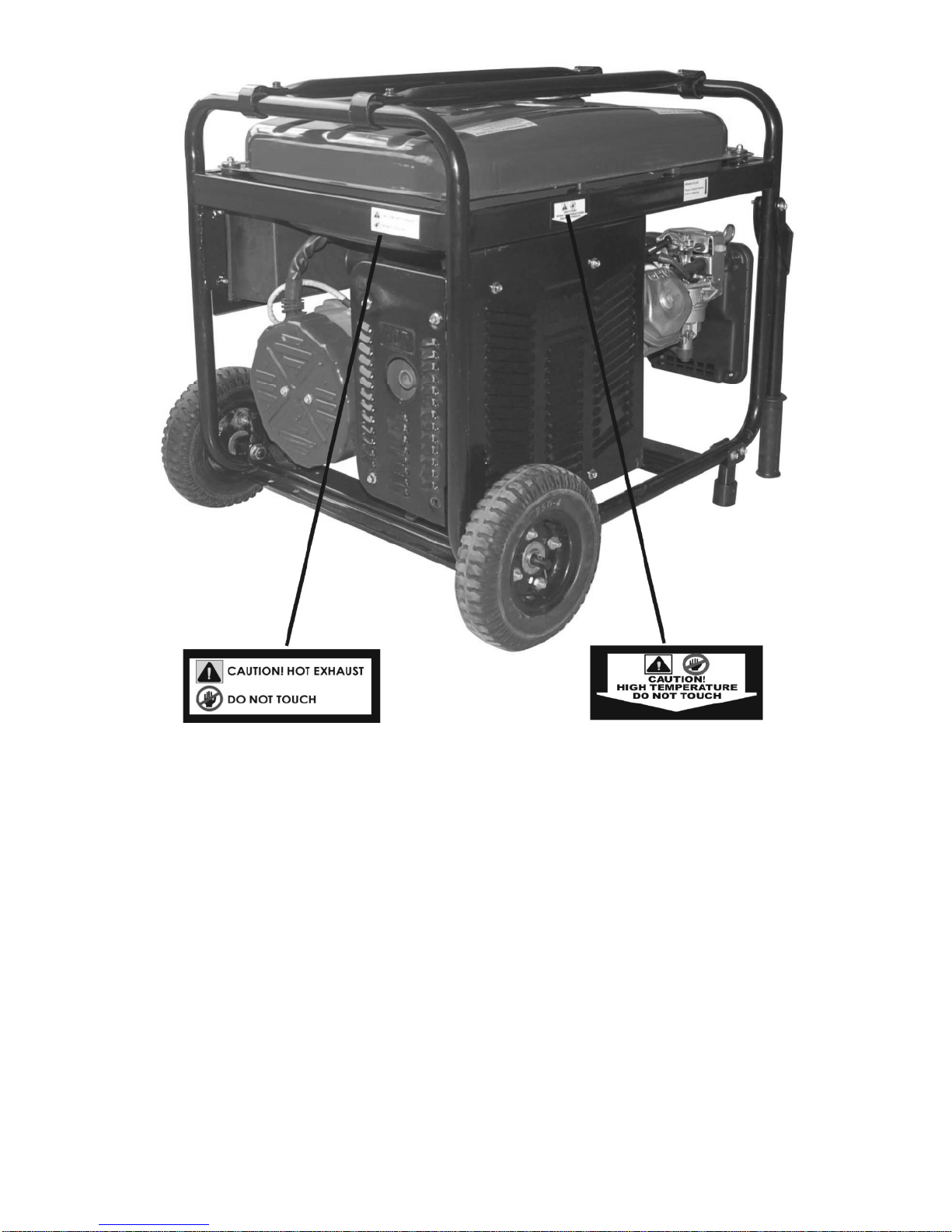
Do not touch hot surfaces. Pay attention to warning labels on the generator
denoting hot parts of the machine.
Allow generator to cool several minutes after use before touching engine or ar eas
which heat during use.
CAUTION: Misuse of this generator can damage it or shorten its life.
Use generator only for its intended purposes.
Operate only on dry, level surfaces.
Allow generator to run for several minutes before connecting electrical dev ices.
Shut off and disconnect any malfunctioning devices from generator.
Do not exceed the Wattage capacity of the generator by plugging in more
electrical devices than the unit can handle.
Do not turn on electrical devices until after they are connected to the generator.
Turn off all connected electrical devices before stopping the generator.
Page 6

6
In addition to the above safety notices, please familiarize yourself with the safety and hazard markings
on the generator.
Page 7
7
Page 8

8
PACKAGE CONTENTS
Your generator comes with the items listed below. Please check to see that all of the following items
are included with your generator.
If you are missing components DO NOT RETURN TO STORE, please call (877) 968-3733
M-F 8-5 CT for customer service.
ITEM LIST
DC Cord
Flat Head
Screwdriver
Rubber
Foot (2 pcs)
NEMA
L14-30
plug
Set of three
wrenches
for
assembly
Wheel (2
pcs)
Instruction
manual
Vinyl Tool
Pouch
Wheel kit
hardware
Spark
plug
wrench
Handle
(2 pcs)
Page 9
9
GENERATOR COMPONENTS
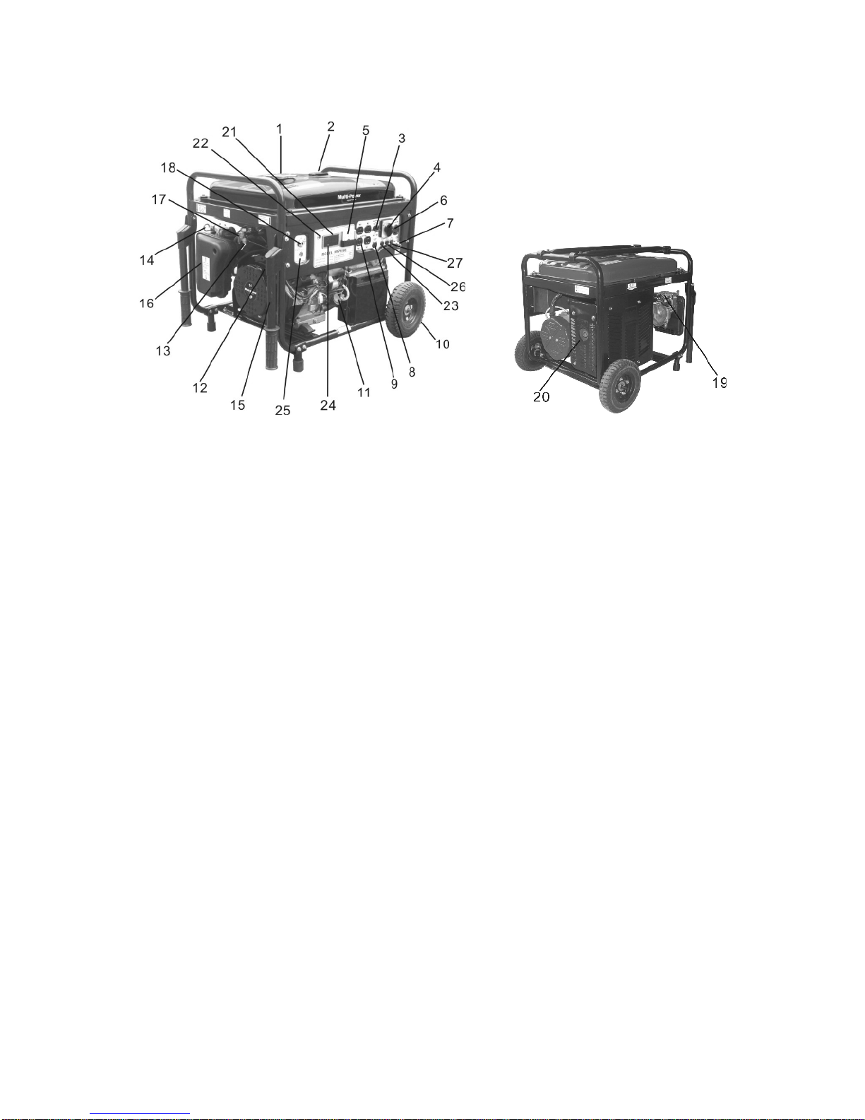
Please familiarize yourself with the locations and functions of the various components and controls of
your generator.
.
(1) Fuel Cap- Access to the fuel tank for adding
fuel.
(2) Fuel Gauge- Indicates the amount of fuel in the
tank.
(3) Circuit Breaker- Set switch that protect the
generator from electrical overload.
(4) Voltage Selector-To switch between 120 and
240 Volt output.
(5) Voltage Meter –Indicate output voltage.
(6) 240/120 Volt AC Receptacle - To connect
electrical devices that run 120 and/or 240 Volt, 60
Hz, single phase, AC current.
(7) Ground Terminal - Connect grounding wires
here to properly ground unit.
(8) DC Output Receptacle- For charging 12 V,
8.3A batteries
(9) 120 Volt AC Duplex Receptacle- To connect
electrical devices that run 120 Volt, 60 Hz, single
phase, AC current.
(10) Wheels- For easy transport.
(11) Oil Fill and Dipstick - Location for checking
and filling engine oil.
(12) Recoil Starter - Pull-cord for starting engine
manually.
(13) Fuel Filter Cup - Traps dirt and water from fuel
before it enters the engine
(14) Choke Lever- Adjusts the amount of air let into the
engine.
(15) Handles- For easy transport.
(16) Air Cleaner- a removable, cleanable, sponge -like
element that limits the amount of dirt pulled into the
engine.
(17) Fuel Valve- Allows fuel to enter engine.
(18) Engine Switch - Used to start/stop engine.
(19) Spark Plug- Provides proper engine ignition.
(20) Muffler- Reduces engine noise.
(21)Hours Meter- showing running time /Frequency/
oil adding reminder
(22) Low Oil Alert - Red lights that turn on to indicate
oil adding.
(23) Control Panel Fuse - Protect DC output circuit.
(24) Hours Meter Reset Button - To switch among
running times,frequency and oil change reading.
(25) DC Circuit Reset Buttons -Protect starting circuit.
(26) Fuel Control Solenoid -for preventing fuel flow
into engine after engine stops
(27) The Battery Charger Fuse -Protecting DC charge
circuit.
Page 10
10
ASSEMBLY
In order to best protect the generator wh ile in the package, this product comes with some components
disassembled. Please complete the following assembly steps before proceeding to use the generator.
For ease of assembly, we recommend attaching the components in the order listed in this manual.
If after reading this section, you are unsure about how to perform any of the steps, please call
(877)968-3733 M-F 8-5 CT for customer service.
WARNING: This generator is heavy. Some assembly procedures may require two people.
Attach Feet
To attach the feet to the generator, perform the following steps:
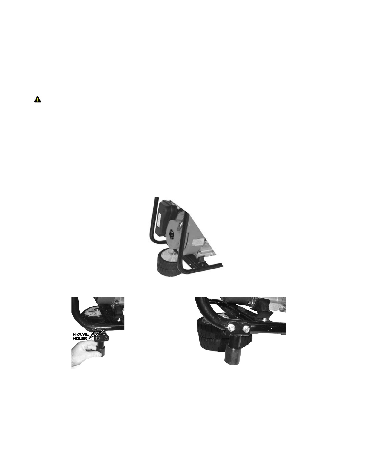
1. Stack the two generator wheels on top of each other. Lift the end of the generator that has the
recoil starter onto the stack of wheels (see figure 1). Be careful not to obstruct any holes on the
generator.
2. Place one leg onto the frame as shown in figure 2. Line up the holes on the generator frame with
the holes on the bracket portion of the leg. Tighten using two M6x40 bolts, two M6 nuts, and the
included wrench.
3. Repeat step 2 for the other generator leg.
Figure 1- Stacking the wheels
a b
Figure 2- foot assembly
Attach Handles
The handles attach to the same end of the generator as the feet. To attach the handles to the generator,
perform the following steps:
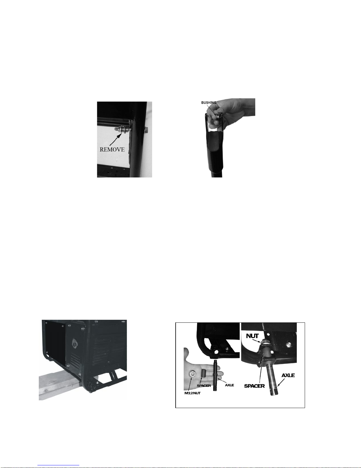
1. The handle assembly consists of the handle, bolt, two bushings, and a nut as shown in figure 3.
Page 11
11
The new generator comes with the bolt, bushings, and nut attached to the fram e. To attach the
handle, first remove these pieces from the frame.
2. Place one bushing into each hole of the handle bracket. The head (large part) of the bushing
should be on the inside of the bracket.
3. Line up the holes on the handle bracket, with bushings attached, the holes on the generator frame.
4. Secure the handle to the frame using the bolt and nut. Make this attachment so that the nut is on
the inside of the frame.
5. Repeat steps 1-4 for the other handle.
At this point, gently remove the two wheels from underneath the generator.
a b
Figure 3- handle assembly
Attach Wheels
To attach the wheels to the generator, perform the following steps:
1. Find a wood block or s imilar item that is 3 inches thick or greater and rest the exhaust end of the
generator on the block as shown in figure 4.
2. Take one wheel shaft, one spacer, and one M12 nut as shown. Place the spacer between the two
holes on the frame bracket. Slide the wheel shaft, with the threaded part facing inward, through the
frame and spacer. Secure using an M12 nut and the included wrench as shown in figure 5.
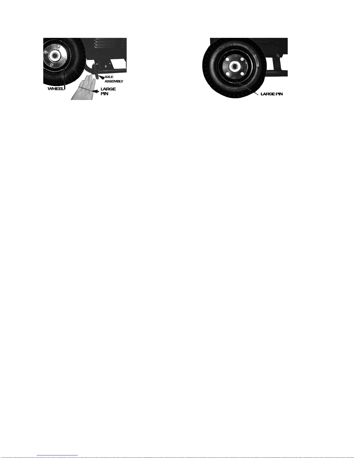
3. Slide the wheel onto the axle and secure in place using a large cotter pin as shown in figure 6.
Spread the pin legs apart slightly to help secure the pin in place.
4. Repeat steps 2 and 3 for the other wheel.
At this point, the generator assembly is complete. Gently remove the generator from the wood block.
Figure 4- supporting the generator Figure 5 - axle assembly
a b
Page 12
12
a Figure 6- wheel installation b
Page 13
13
PREPARING THE GENERATOR FOR USE
Using the Generator for the First Time
The following section describes steps you must follow to prepare your gene rator for first-time
use. If after reading this section, you are unsure about how to perform any of the steps please call
(877) 968-3733 M-F 8-5 CT for customer service. Failure to perform these steps properly can
damage your generator or shorten its li fe.
If you are using the generator for the first time, there are a few steps you must take to prepare it for
operation:
Step 1- Add oil
The generator requires engine oil to operate properly. The generator, when new from the package,
contains no oil in the crankcase. You must add the proper amount of oil before operating the generator
for the first time. This amount, which is equal to the oil capacity of the engine crankcase, can be found
on the chart in figure 6. When filling the engine with oil in the future, please refer to this chart.
Figure 6- Generator Oil Capacity
Model number
MP3501
MP3502
MP5500DF
MP6000E
MP7500E
Engine oil capacity
20 fluid oz.
20 fluid oz.
37 fluid oz
37 fluid oz.
37 fluid oz.
For general use, we recommend SAE 10W/30 o il to fill the engine crankcase.
To add oil, follow these steps:
1. Make sure the generator is on a level surface.
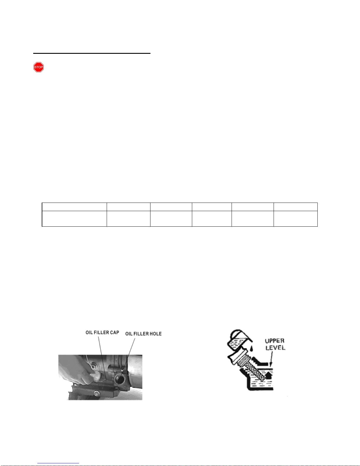
2. Unscrew the oil filler/dipstick cap from the engine as shown in figure 7.
3. Using a funnel, add the appropriate amount of oil, as found in figure 6, into the crankcase.
NOTE: Even if you have measured out the appropriate amount of oil, some spillage is common
when filling. You will know the crankcase is full when the oil level has reached the lower lip of
the opening you have just poured the oil i nto (see figure 7).
4. Replace oil filler cap.
Figure 7- Unscrewing the oil cap Figure 8- Adding oil
Page 14

14
Step 2- Add Gasoline
WARNING: Gasoline and gas fumes are highly flamm able.
Do not fill tank near an open flame.
Do not overfill. Always check for fuel spills.
To ensure that the generator runs smoothly use only FRESH, UNLEADED GAS WITH AN OCTANE
RATING OF 87 OR HIGHER. To add gasoline:
1. Make sure the generator is on a le vel surface.
2. Unscrew gas cap and set aside (NOTE: the gas cap may be tight and hard to unscrew).
3. Slowly add unleaded gasoline to the fuel tank. Be careful not to overfill. Please refer to the
chart in figure 9 to find the gas capacity of your generator mod el. The fuel gauge on the top of
the generator indicates how much gasoline is in the generator gas tank. NOTE: Gas can expand.
Do not fill the gas tank to the very top.
4. Replace fuel cap and wipe up any spilled gasoline with a dry cloth.
IMPORTANT:
Never use an oil/gasoline mixture.
Never use old gas.
Avoid letting dirt or water into the fuel tank.
Gas can age in the tank and make it hard to start up the generator in the future. Never store
generator for extended periods of time with fuel in the tank.
Figure 9- Gas Tank Capacity
Model number
MP3501
MP3502
MP5500DF
MP6000E
MP7500E
Gas tank
capacity
3.6L
(0.95gallons)
15 L
(3.96gallons)
25L
(6.60gallons)
25L
(6.60gallons)
25L
(6.60gallons)
Step 3- Ground the Generator
WARNING: Failure to properly ground the generator can result in electrocution.
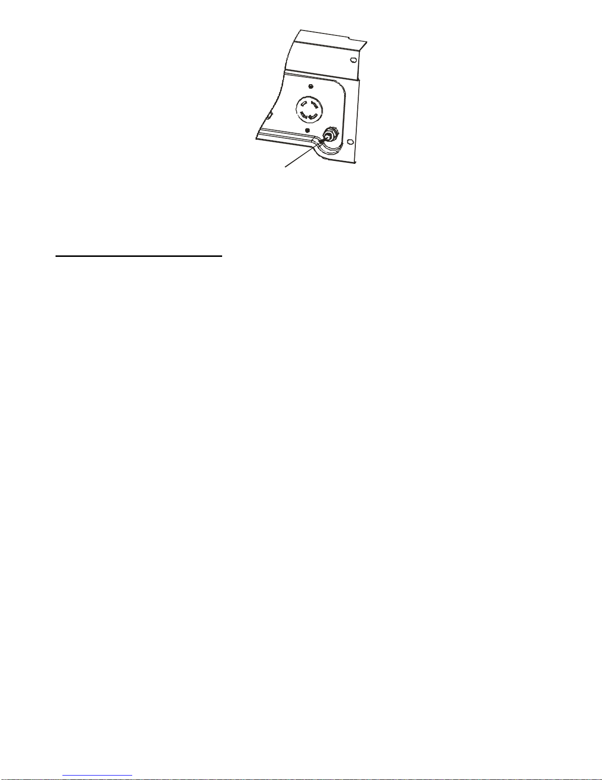
Ground the generator by tightening the grounding nut against a grounding wire (see figure 1 0). A
generally acceptable grounding wire is a No. 12 AWG (American Wire Gauge) stranded copper wire.
This grounding wire should be connected at the other end to a copper or brass grounding rod that is
driven into the earth.
Grounding codes can vary by location. Please contact a local electrician to check the grounding
regulations for your area.
Page 15
15
Grounding
Wing Nut
Figure 10- Grounding nut location
Subsequent Use of the Generator
If this is not your first time us ing the generator there are still steps you should take to prepare it for
operation.
IMPORTANT: At this point you should be familiar with the procedures described in the first
portion of this section entitled “Using the Generator for the First Time.” If y ou have not yet read
this section, go back and read it now.
Step 1- Check the Oil
The generator is equipped with an automatic shutoff to protect it from damage due to low oil.
Nonetheless, you should check the oil level of the engine before each use to ensure that the engine
crankcase has a sufficient amount. To check the oil level:
1. Make sure the generator is on a level surface.
2. Unscrew the oil filler/dipstick cap.
3. With a dry cloth, wipe the oil off of the stick on the inside of the cap.
4. Insert the dipstick as if you were replacing the cap and then remove again. There should now
be oil on the stick. If there is no oil on the stick, or oil only at the very end of the stick, you
should add oil until the engine crankcase is filled (see “ Changing/Adding Oil” portion of the
“Maintenance” section).
5. Be sure to replace cap when finished checking oil.
NOTE: The oil capacity for your generator can be found in the “Specifications” section of this manual
Page 16

16
Step 2 – Check the Gas Level
Before starting the generator , check to see that there is sufficient gasoline in the gas tank. The fuel
gauge on top of the generator will indicate the gas level in the tank. Add gas if necessary according to
the steps in the “Adding Gasoline” portion of the “Maintenance” section.
WARNING: Gasoline and gasoline fumes are highly flammable.
Do not fill tank near an open flame.
Always allow engine to cool for several minutes before refueling.
Do not overfill (check the “Specifications” section for the tank capacity of your generato r).
Always check for fuel spills.
IMPORTANT:
Use only UNLEADED gasoline with an octane rating of 87 or higher.
Do not use old gas.
Never use an oil/gasoline mixture.
Avoid letting dirt or water into the fuel tank.
Never store generator for extended per iods of time with fuel in the tank.
Step 3- Ground the Generator
WARNING: Failure to properly ground the generator can result in electrocution.
Ground the generator by tightening the grounding nut against a grounding wire (see figure 11). A
generally acceptable grounding wire is a No. 12 AWG (American Wire Gauge) stranded copper wire.
This grounding wire should be connected at the other end to a copper or brass grounding rod that is
driven into the earth.
Grounding codes can vary by location. Please contact a local electrician to check the grounding
regulations for your area.
Page 17
17
STARTING THE GENERATOR
Before starting the generator, make sure you have read and performed the steps in the
“Preparing the Generator for Use” section of this manual. If you are unsure about how to perform
any of the steps in this manual please call (877) 968-3733 M-F 8-5 CT for customer service.
CAUTION: Disconnect all electrical loads from the generator before attempting to start.
To start your generator, perfor m the following steps:
1. Make sure no electrical devices are connected to the generator. Such devices can make it
difficult for the engine to start.
2. Check that the generator is properly grounded (see “Ground the Generator”).
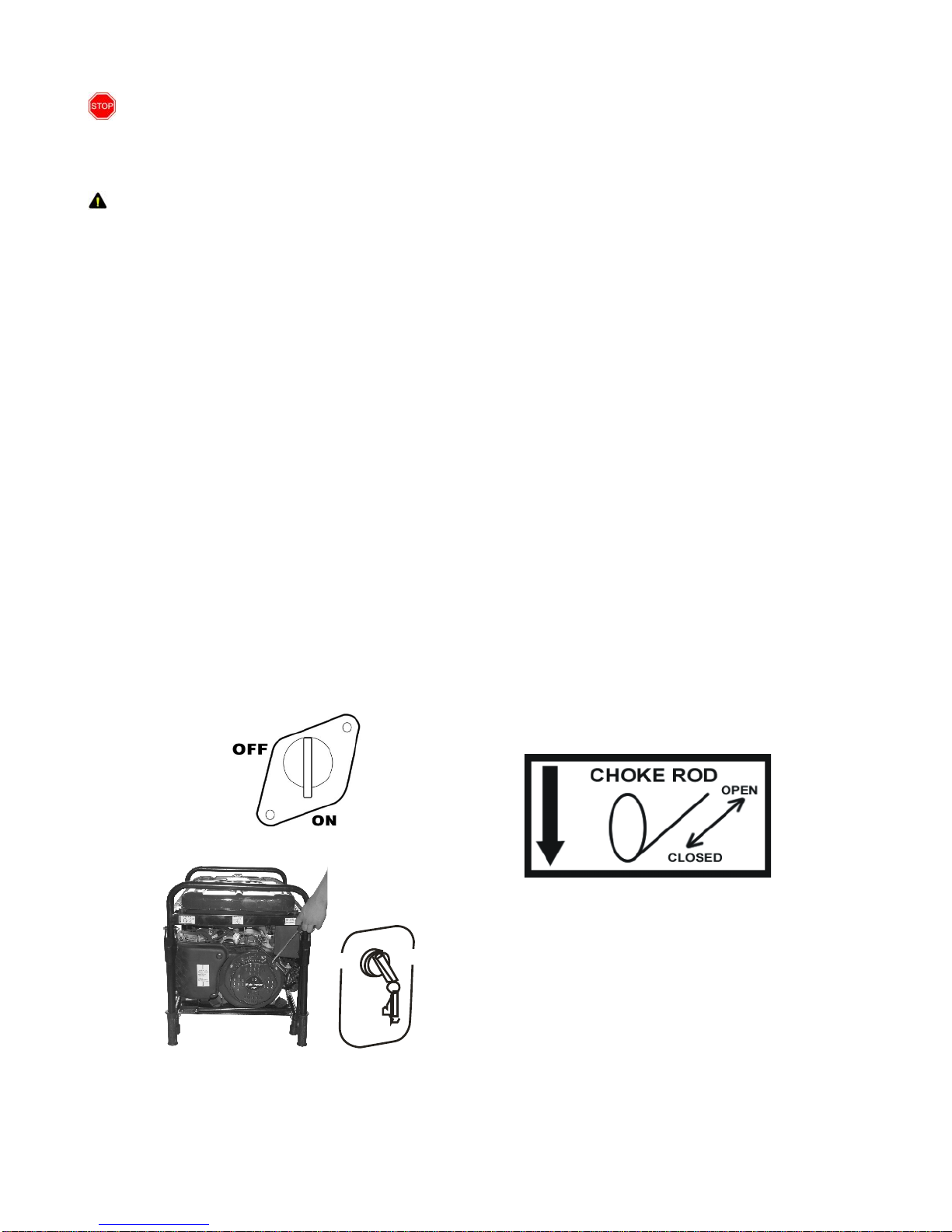
3. Turn the fuel valve to the “on” p osition (see figure 1 1).
4. Move the choke lever to the “closed” position (see figure 13).
5. Turn on the key switch to “start” position,not more than 15 seconds for every time, if succeed,
release th key, if fail,have a second try in the same way.(see figure 12 )
6. If the engine doesn’t work when you start with key,please try to start with recoil starter.(see
figure 12)
7. Pull on the recoil starter handle slowly until a slight resistance is felt (see figure 1 2). Then pull
quickly to start the engine. Return cord gen tly into the machine. Never allow the cord to snap
back.
8. If engine fails to start, repeat step 6. NOTE: After repeated failed attempts to start the engine,
please consult the troubleshooting guide before attempting again. If problems persist please ca ll
(877) 968-3733 M-F 8-5 CT.
9. Once the engine has started, move the choke lever about half way towards the “open” position.
Wait 30 seconds and then move the choke lever all the way to the “open” position.
10. Allow the generator to run for several minutes before attempting to connect any electrical
devices.
Figure 11- Fuel Valve in the “on” position
ON
OFF
STA RT
Figure 12- Start the generator
Figure 13- Pull choke out for closed position.
Push in for open position.
Page 18
18
USING THE GENERATOR
Once you have allowed the engine to run for several minutes, you may connect electrical devices to the
generator.
AC Usage
CAUTION: Please familiarize yourself with the markings on the panel before connecting electrical
devices.
You may connect electrical devices running on AC current according to their wattage requirements.
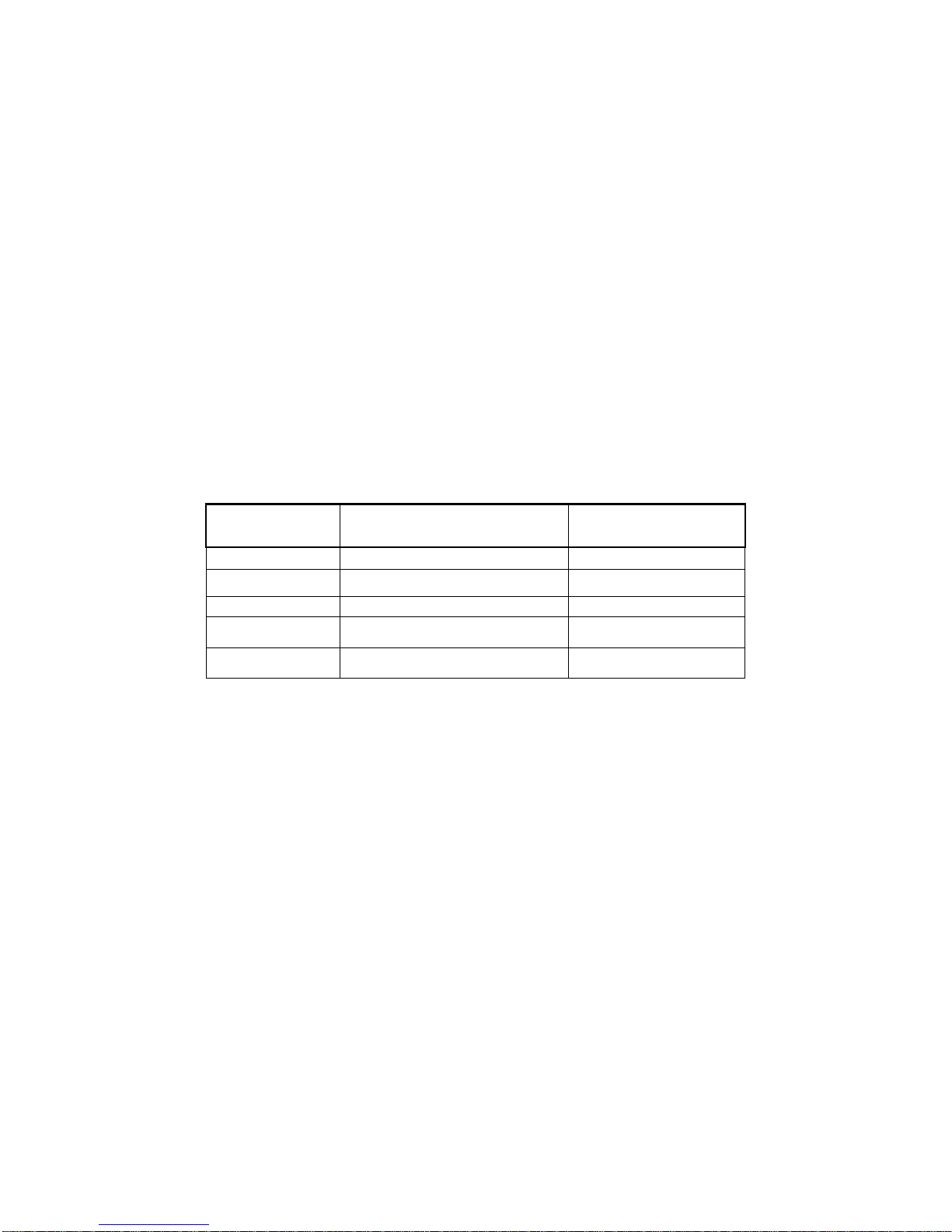
The chart in figure 1 4 shows the rated and surge wattage of your generator according to its model
number.
CAUTION: Although the overall rated wattage of the machine is 7000 Watts, you never attempt to
draw more than 2400 Watts(20 A) from any ONE of the 120 Volt receptacles.
The rated wattage corresponds to the maximum wattage the generator can output on a continuous basis.
The surge wattage corresponds to the maximum amount of power the generator can output for a short
period of time. Many electrical devices such as refrigerators require short bursts of extra power, in
addition to the rated wattage listed by the device, to stop and start their motors. T he surge wattage
ability of the generator covers this extra power requirement.
Model Number
Rated(Running) Wattage
Surge Wattage
MP3501
3000
3500
MP3502
3000
3500
MP5500DF
5000
5500
MP6000E
5500
6000
MP7500E
7000
7500
Figure1 4- generator wattage by model number.
The total running wattage requirement of the electrical devices connected to the generator should not
exceed the rated wattage of the generator itself. To calculate the total wattage requirement of the
electrical devices you wish to conne ct, find the rated (or running) wattage of each device. This number
should be listed somewhere on the device or in its instruction manual. If you cannot find this wattage,
you may calculate it by multiplying the Voltage requirement by the Amperage drawn:
Watts= Volts x Amperes
If these specifications are not available, you may estimate the Watts required by your device using the
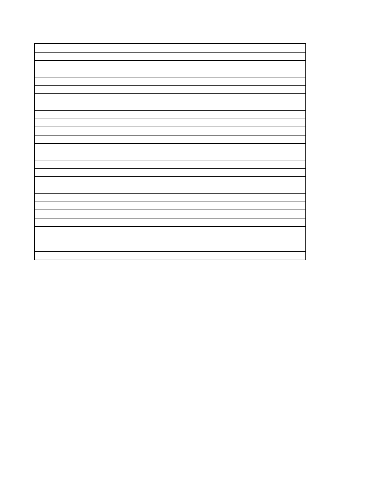
chart in figure 15.
Once you have found the rated wattage requirement of each electrical device, add these numbers to find
the total rated wattage you wish to draw from the generator. If this number exceeds the rated wattage
of the generator, DO NOT connect all these devices. Select a combination of electrical devices, which
has a total rated wattage lower than or equal to the rated wattage of the generator.
CAUTION- The generator can run at its surge wattage capacity for only a short time. Connect
electrical devices requiring a rated (running) wattage equal to or less than the rated wattage of
Page 19
19
the generator. Never connect de vices requiring a rated wattage equal to the surge wattage of the
generator.
tool or appliance
rated (running) Watts
additional surge Watts
electric water heater (40 gal)
4000
0
hot plate
2500
0
saw- radial arm
2000
2000
electric stove
1500
0
saw- circular
1500
1500
air compressor (1 HP)
1500
3000
window air conditioner
1200
1800
saw- miter
1200
1200
microwave
1000
0
well water pump
1000
1000
reciprocating saw
960
1040
sump pump
800
1200
refrigerator freezer
800
1200
furnace blower
800
1300
computer
800
0
electric drill
600
900
television
500
0
deep freezer
500
500
garage door opener
480
0
stereo
400
0
box fan
300
600
clock radio
300
0
security system
180
0
DVD player/ VCR
100
0
common light bulb750
NOTE: The above wattage figu res are estimates. Try to check the wattage listed on your electrical
device before consulting this chart.
Figure 15- Estimated wattage requirements of common electrical devices.
Once you have determined what electrical devices you will be powering with the generator, connect
these devices according to the following procedure:
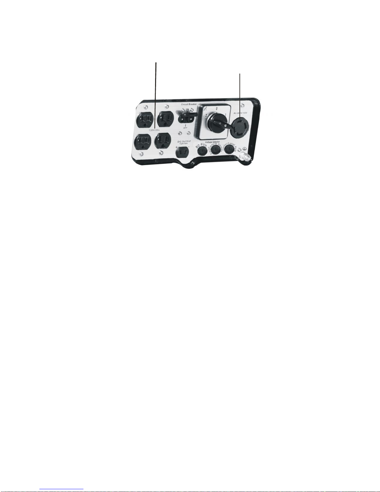
1. Plug in each electrical device with the device turned off. NOTE: Be sure to attach appliances to
the correct receptacle (outlet). Connect standard 120 Volt, single phase, 60 Hz l oads only to the
120 Volt receptacles. Connect 2 40/120 Volt, single phase, 60Hz loads with a NEMA L14 -30
plug only to the 240/120 Volt receptacle See Figure 1 6 for a depiction of each of these
receptacles.
2. Push the circuit breaker to the “on” position .
3. Move the voltage selector to the desired position. Move the switch to the left to use the standard
120 Volt receptacles. Move the switch to the right to use the 240/120 Volt NEMA receptacle.
4. The voltage meter will indicate accordingly as the Volt Selector is selected. It works when the
receptacles receive power. In the case of the 240/120 Volt receptacle, it will indicate 240V ±
20V. In the case of the 240/120 Volt receptacle, it indicates 120V ±10V.If the voltage meter
does not indicate accordingly or indicate wrong, call our customer service number for
instructions.
Page 20
20
CAUTION: Do not connect 50Hz or 3 -phase loads to the generator .
120V/20A AC Duplex
Receptacles
240/120VAC
Receptacle
(L14-30)
Figure 16- Receptacles available on the generator
CIRCUIT BREAKER
The circuit breakers help to prevent the generator fro m electrical overload. If your receptacle short
circuits or becomes overloaded by an electrical device or devices with too great a wattage rating, the
circuit protector may shut off power to the receptacle. If this happens, you will see the voltage meter
changing from having voltage output to no voltage. and you will not be able to draw power from the
overloaded receptacle. In the event of such an overload, disconnect all electrical devices from the
generator and press the circuit breaker to “ON” position. If power still does not return to the receptacle,
call our customer service line.
ATUOMATIC IDLE REDUCTION
When load≥100W(0.83A), the generator will run from automatic idle reduction state to normal
running state. The transition will be finished within 20 seconds.
When load ≤60W(0.5A), the generator may run from normal running state to automatic idle reduction
state. The transition will be finished within 30 seconds.
SOME NOTES ABOUT POWER CORDS
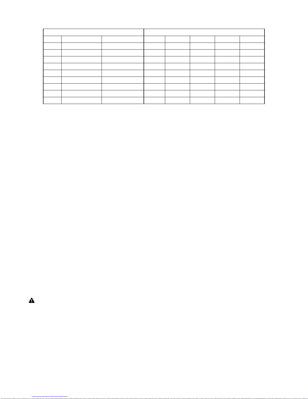
Long or thin cords can drain the power provided to an electrical device by the generator. When using
such cords, allow for a slightly higher rated wattage requirement by the electrical device. See Figure
17 for recommended cords based on the power requirement of the electrical device.
Page 21
21
Device Requirements
Max. Cord Length (ft) by Wire Gauge
Amps
Watts (120V)
Watts (240 V)
#8 wire
#10 wire
#12 wire
#14 wire
#16 wire
2.5
300
600
NR
1000
600
375
250
5
600
1200
NR
500
300
200
125
7.5
900
1800
NR
350
200
125
100
10
1200
2400
NR
250
150
100
50
15
1800
3600
NR
150
10065NR
20
2400
4800
175
1257550
NR
25
3000
6000
150
10060NR
NR
30
3600
7200
12565NRNRNR
40
4800
9600
90NRNRNRNR
*NR= not recommended
Figure 17- Maximum Extension Cord Lengths by Power Requirement
DC Usage
CAUTION: The DC receptacle is for charging 12 Volt 8.3A batteries ONLY. Do not connect any
other device to this receptacle.
CAUTION: Only charge batteries when they are removed from the automobile. Never try to
“jumpstart” a car using the generator.
To connect 12 Volt batteries to the DC receptacle:
1. Connect the positive end of charging wire to the positive terminal on the battery.
2. Connect the other end of charging wire to the negative terminal on the battery.
3. Start the generator.
4. Carefully connect the plug of charging wire to V shape DC receptacle on the generator.
STOPPING THE GENERATOR
To stop the generator:
1. Turn off, then unplug all connected electrical devices.
2. Allow the generator to run for several more minutes with no electrical devices connected. This
helps stabilize the temperature of the generator.
3. Set the engine switch to the “off” position.
4. Turn the fuel valve to the “off” position.
WARNING: Allow the generator to cool for several minutes before touching areas that
become hot during use.
CAUTION: Allowing gas to sit in the generator tank for long periods of time without use can
make it difficult to start the gen erator in the future. Never store generator for extended periods
of time with fuel in the tank.
Page 22
22
MAINTENANCE / CARE
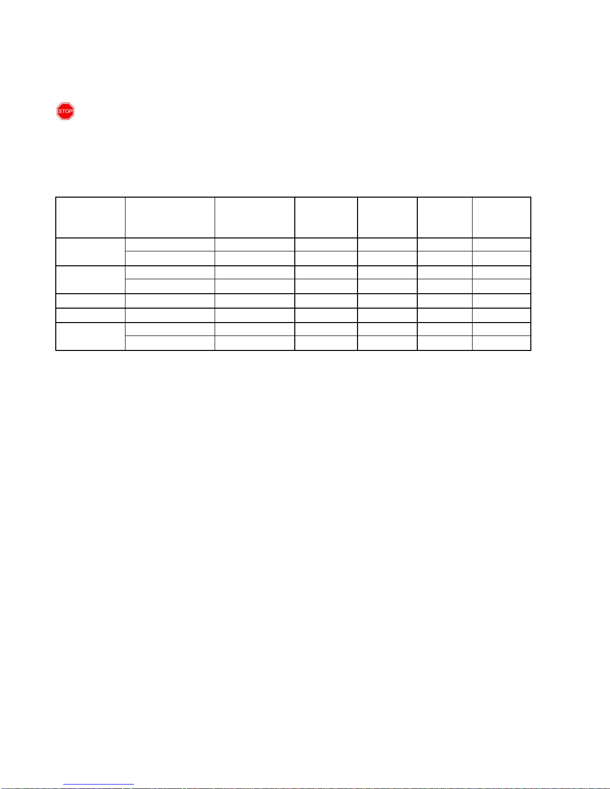
Proper routine maintenance of your generator will help prolong the life of your machine. Please
perform maintenance checks and operati ons according the schedule in figure 1 8.
If you have questions about any of the maintenance procedures listed in this manual, please call
(877) 968-3733 M-F 8-5 CT
CAUTION: Never perform maintenance operations while the generator is running.
Recommended Maintenance Schedule
each use
first month
then every
20 hrs
every 3
months or
50 hrs
every 6
months or
100 hrs
every year
or 300 hrs
check level
x
Engine oil
replacexx
check
x
Air cleaner
clean
x
Fuel filter cup
clean
x
Spark plug
check/ clean
x
check gas level
x
Gas tank
clean
x
Figure 18- Recommended maintenance schedule
Cleaning the Generator
Always try to use your generator in a cool dry place. In the event t he generator becomes dirty, clean the
exterior with one or more of the following:
- a damp cloth
- a soft brush
- a vacuum
- pressurized air
Never clean the generator with a bucket of water or a hose. Water can get inside the working parts of
the generator and cause a short circuit or corrosion.
Checking the Oil
The generator is equipped with an automatic shutoff and low oil indicator to protect it from running on
low oil. Nonetheless, you should check the oil level of the generator before each use to ensure t hat the
generator crankcase has a sufficient amount. To check the oil level:
1. Make sure the generator is on a level surface.
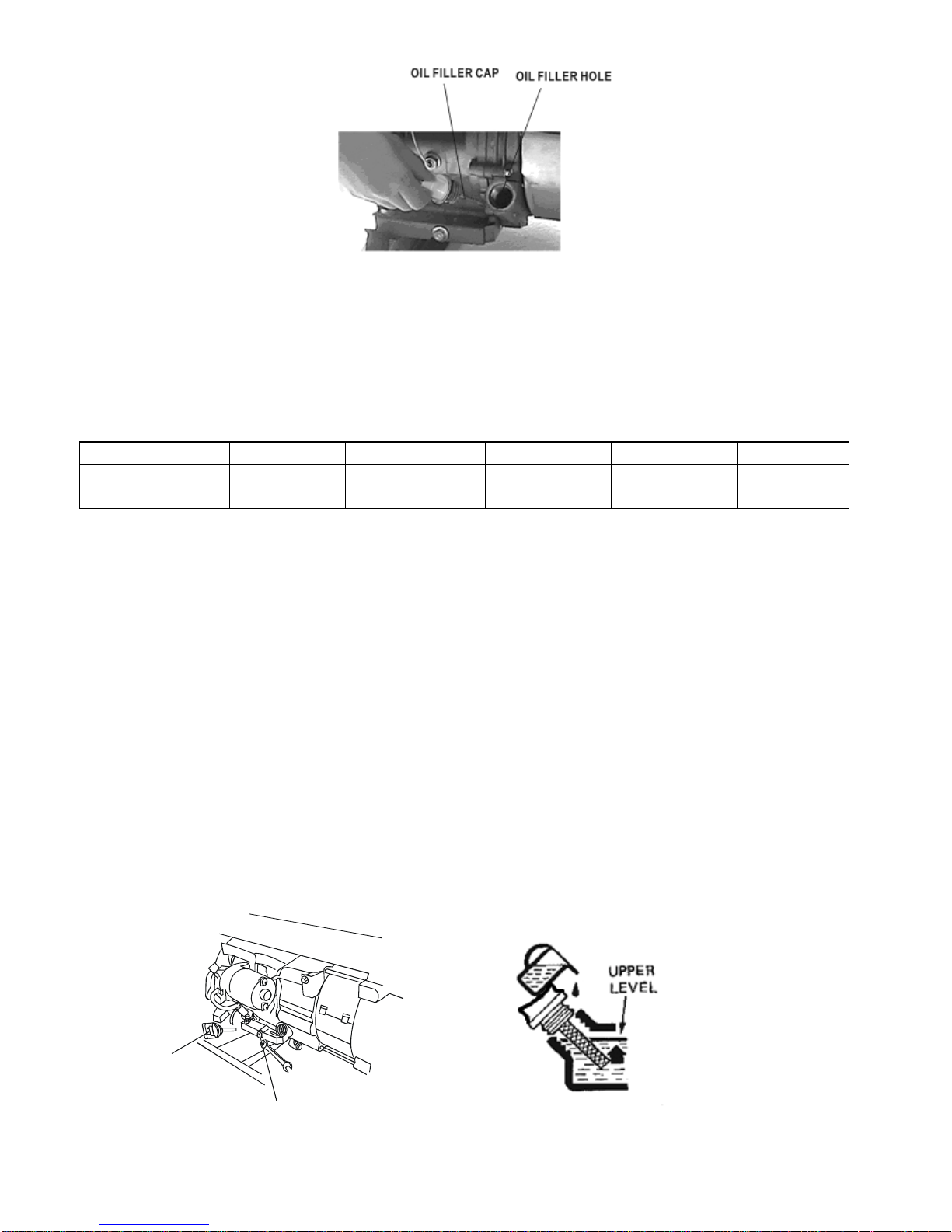
2. Unscrew the oil filler/dipstick cap (see figure 19).
3. With a dry cloth, wipe the oil off of the stick on the inside of the cap.
4. Insert the dipstick as if you were replacing the cap and then remove again. There should now
be oil on the stick. If there is no oil on the stick, or oil only at the very end of the stick, you
should add oil until the engine crankcase is filled. See “Changin g/ Adding Oil” in this section.
5. Be sure to replace cap when finished checking oil.
Page 23
23
Figure19- Checking the oil
Changing/ Adding Oil
You should check the oil level of the generator according to the maintenance schedule in figure 19.
When the oil level is low you will need to add oil until the level is sufficient to run the generator.
The oil capacity of your generator engine is listed in figure 2 0.
Model Number
MP3501
MP3502
MP5500DF
MP6000E
MP7500E
Engine oil
capacity
20 fluid oz.
20 fluid oz.
37 fluid oz
37 fluid oz
37 fluid oz.
Figure 20- Engine Oil Capacity.
It is necessary to drain the oil from the crankcase every 3 months or Hours Meter shows “OFF”, or if it
has become contaminated with water or dirt. Drain the oil from the generator accordi ng to the
following steps:
1. Place a bucket underneath the generator to catch oil as it drains.
2. Using a 10 mm hex wrench, unscrew the oil drain plug, which is located on the crankcase
underneath the oil filler/dipstick cap (see figure 2 1). Allow all the oil to drain from the
generator.
3. Replace the oil drain plug and tighten with a 10 mm hex wrench.
To add oil to the crankcase, follow these steps:
1. Make sure the generator is on a level surface.
2. Unscrew the oil filler/dipstick cap from the engine as shown in fi gure 20 above.
3. Using a funnel, add high detergent motor oil to the crankcase. We recommend SAE 10W/30
motor oil for general use. When full, the oil level should come close to the top of the oil fill
opening (see figure 22).
FILLER CAP
DRAIN PLUG
Figure 21- Draining oil Figure 2 2- Adding oil
Page 24
24
NOTE: Never dispose of used motor oil in the trash or down a drain. Please call your local
recycling center or auto garage to arrange oil disposal.
Air Cleaner Maintenance
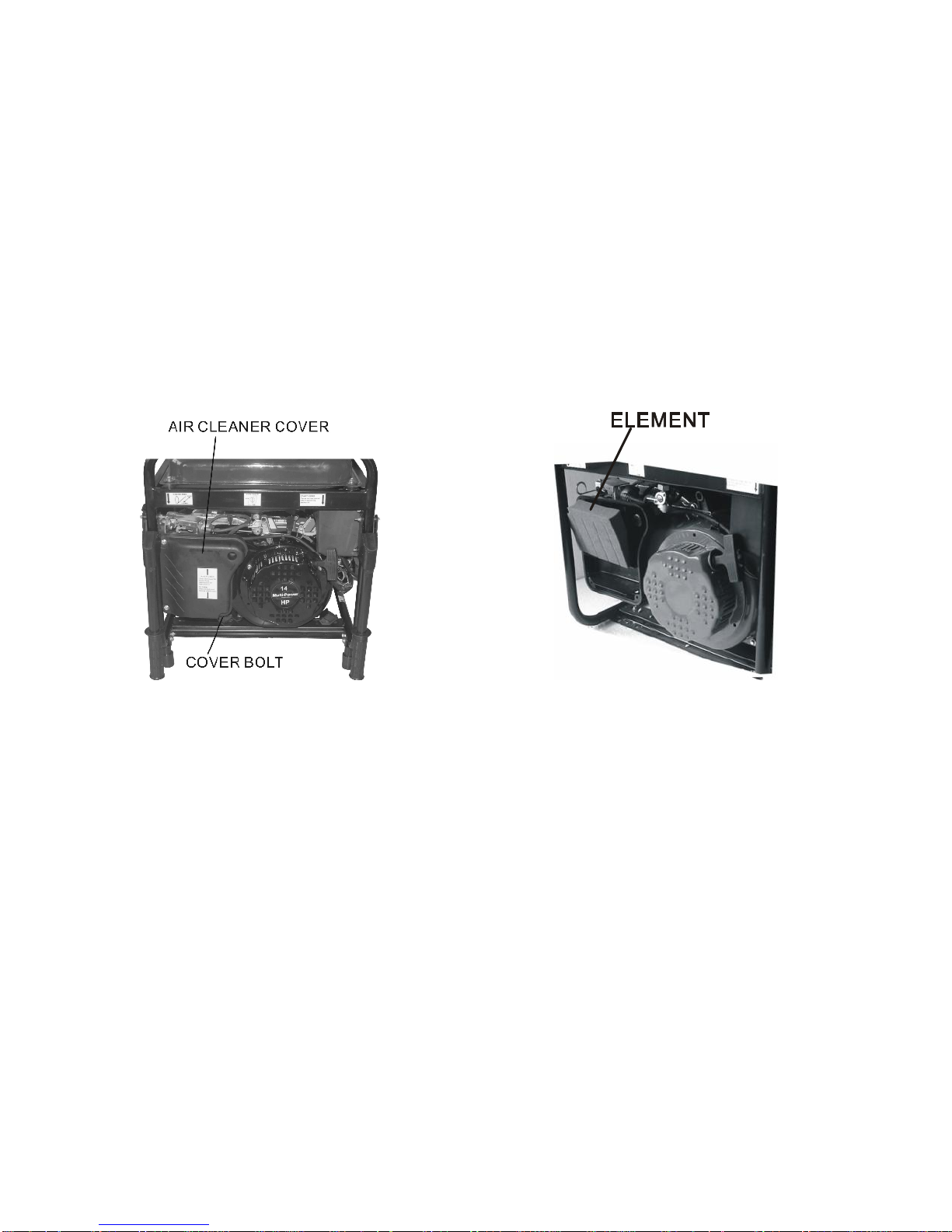
Routine maintenance of the air cleaner helps maintain proper air flow to the carburetor. Check that the
air cleaner is free of excessive dirt.
1. Unhinge the clasps at the top and bottom of the air cleaner cover (see figure 2 3).
2. Remove the sponge-like elements from the casing.
3. Wipe the dirt from inside the empty air cleaner casing
4. Wash the sponge-like elements in household detergent and warm water. Allow to dry.
5. Replace the sponge-like elements in the air cleaner casing and replace the cover.
Figure 23- Removing the air cleaner casing.
Fuel Filter Cup Cleaning
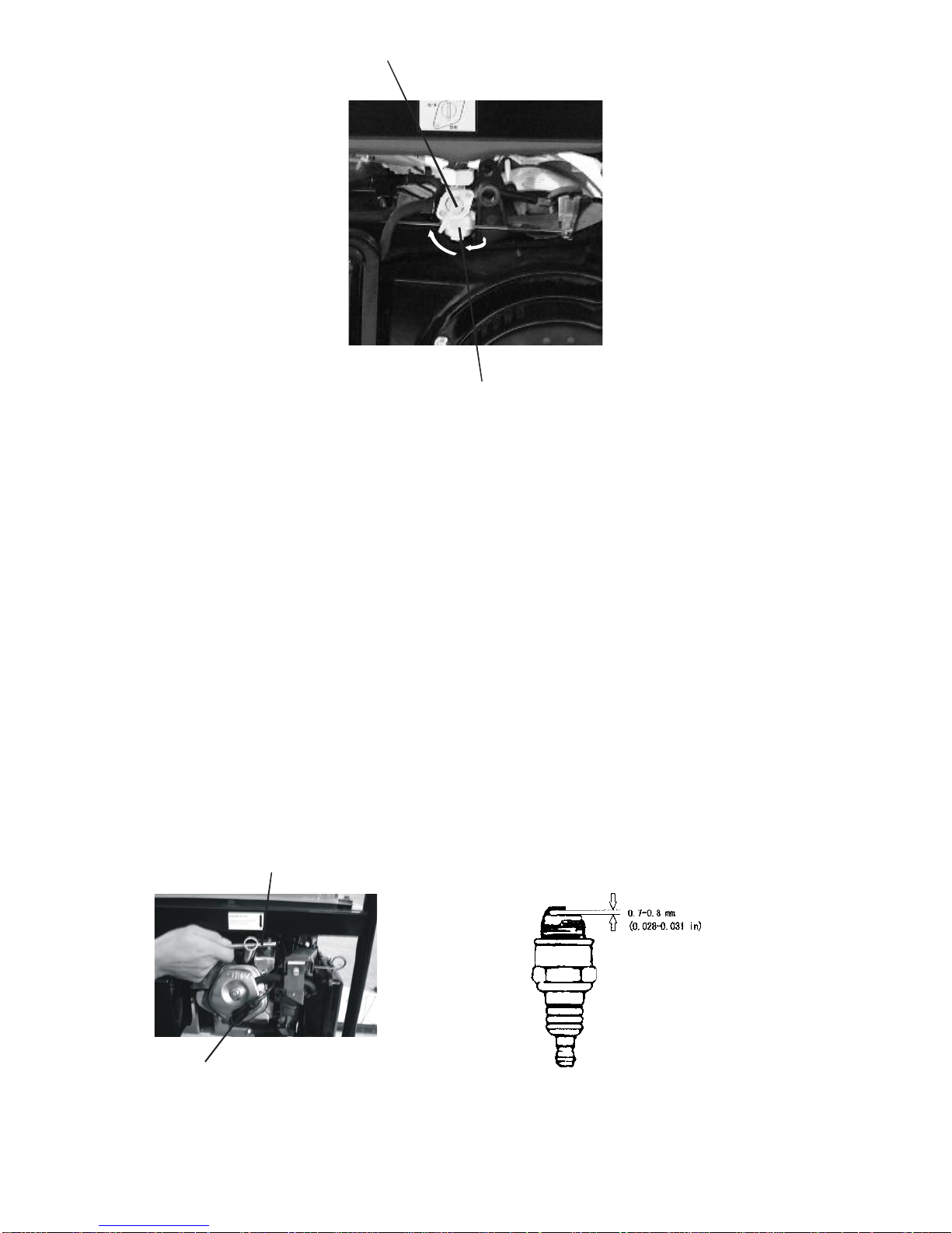
The fuel filter cup is a small well underneat h the fuel valve. It helps to trap dirt and water that may be
in the fuel tank before it can enter the engine. To clean the fuel filter cup:
1. Turn the fuel valve to the “off” position.
2. Unscrew the fuel filter cup from the fuel valve using a wrench. Turn t he valve toward you to
unscrew (see figure 24).
3. Clean the cup of all sediment using a rag or brush.
4. Reinstall the fuel filter cup.
Page 25
25
FUEL FILTER CUP
FUEL VALVE
Figure 24- Removing the Fuel Filter Cup
Spark Plug Maintenance
The spark plug is importa nt for proper engine operation. A good spark plug should be intact, free of
deposits, and properly gapped. To inspect the spark plug:
1. Pull on the spark plug cap to remove it.
2. Unscrew the spark plug from the generator using the spark plug wrench included with this
product (see figure 25).
3. Visually inspect the spark plug. If it is cracked or chipped, discard and replace with a new
spark plug.
4. Measure the plug gap with a gauge (see figure 2 6). The gap should be 0.7 -0.8mm (0.028-
0.031in).
5. If you are re-using the spark plug, use a wire brush to clean any dirt from around the spark plug
base and then re-gap the spark plug.
6. Screw the spark plug back into its place on the generator using the spark plug wrench. Place
back the spark plug cap.
PLU G WRENCH
PLUG CAP
Figure 25- Removing the spark plug Figure 2 6- Measuring the spark plug gap
Page 26

26
Emptying the Gas Tank
Before storing the generator for extended periods of time, you should drain the generator of gasoli ne.
To drain the generator of gas:
1. Turn the fuel valve to the “off” position.
2. Remove the fuel filter cup (see “ Fuel Filter Cup Cleaning ” earlier in this section ).
3. Empty the fuel filter cup of any fuel.
4. With a receptacle underneath the generator to catch t he gas, turn the fuel valve to the “on”
position. Drain all the gas from the generator.
5. Turn the fuel valve to the “off” position.
6. Replace the fuel filter cup.
7. Store the emptied gasoline in a suitable place.
CAUTION: Do not store fuel from one season to another.
STORAGE / TRANSPORT PROCEDURES
CAUTION: Never place any type of storage cover on the generator while it is still hot.
When transporting or storing the generator for extended periods of time:
Empty the gas tank (see “Emptying the Gas Ta nk” in the “Maintenance” section).
Disconnect the spark plug cap from the spark plug.
Do not obstruct any ventilation openings.
Keep the generator in a cool dry area.
Page 27
27
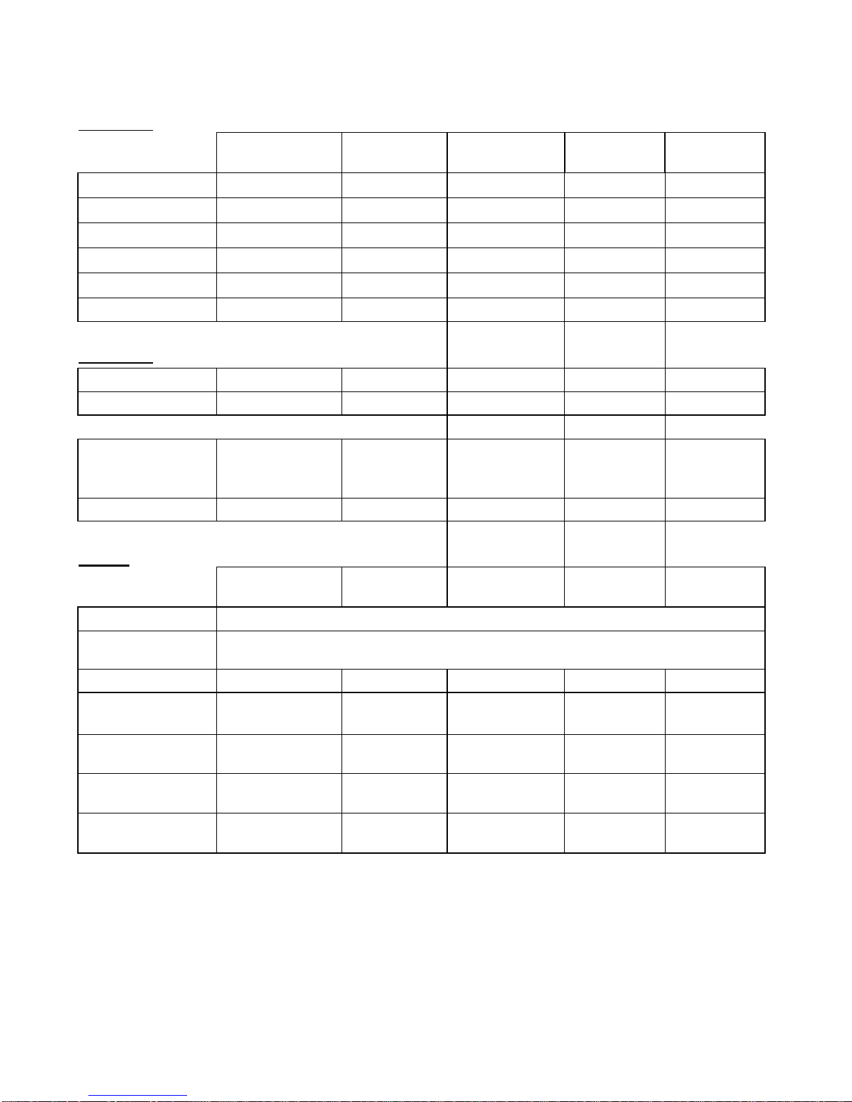
SPECIFICATIONS
Generator
AC Output
Model
MP3501
Model
MP3502
Model
MP5500DF
Model
MP6000E
Model
MP7500E
Rated Wattage
3000 W
3000 W
5000 W
5500W
7000 W
Surge Wattage
3500 W
3500 W
5500 W
6000W
7500 W
Rated Voltage
120 V
240V/120V
240V/120V
240V/120V
240V/120V
Rated Amperage
25A
12.5A/25A
20.8A/41.6A
22.9A/45.8A
29A/58A
Rated Frequency
60 Hz
60 Hz
60 Hz
60 Hz
60 Hz
Phase
Single
Single
Single
Single
Single
DC Output
Voltage
12 V
12 V
12 V
12 V
12 V
Amperage
8.3 A
8.3 A
8.3 A
8.3 A
8.3 A
Dimensions(in):
length= 23
width=15.9
height= 16.3
length= 24
width= 17.7
height= 18.5
length= 27.6
width= 21.1
height= 22.1
length= 27.6
width= 21.1
height= 22.1
length= 27.6
width= 21.1
height= 22.1
Dry mass
77lbs
104 lbs
191lbs
191lbs
200lbs
Engine
Model
MP3501
Model
MP3502
Model
MP5500DF
Model
MP6000E
Model
MP7500E
Engine type
4-stroke OHV single cylinder with forced air cooling system
Ignition system
non-contact transistor
Displacement
196 cm
3
196 cm
3
389 cm
3
389 cm
3
420 cm
3
Fuel tank capacity:
3.6L
(0.95 US gal)
15 L
(3.96 US gal.)
25 L
( 6.60 US gal.)
25 L
( 6.60 US gal.)
25 L
( 6.60 US gal.)
Oil capacity
0.6 L
(20 fl oz.)
0.6 L
(20 fl oz.)
1.1 L
(37 fl oz.)
1.1 L
(37 fl oz.)
1.1 L
(37 fl oz.)
Run time on 50%
load
4hrs
15 hrs
12 hrs
11hrs
8hrs
Noise rating
69 dB
67dB
74dB
74dB
75 dB
Page 28
28
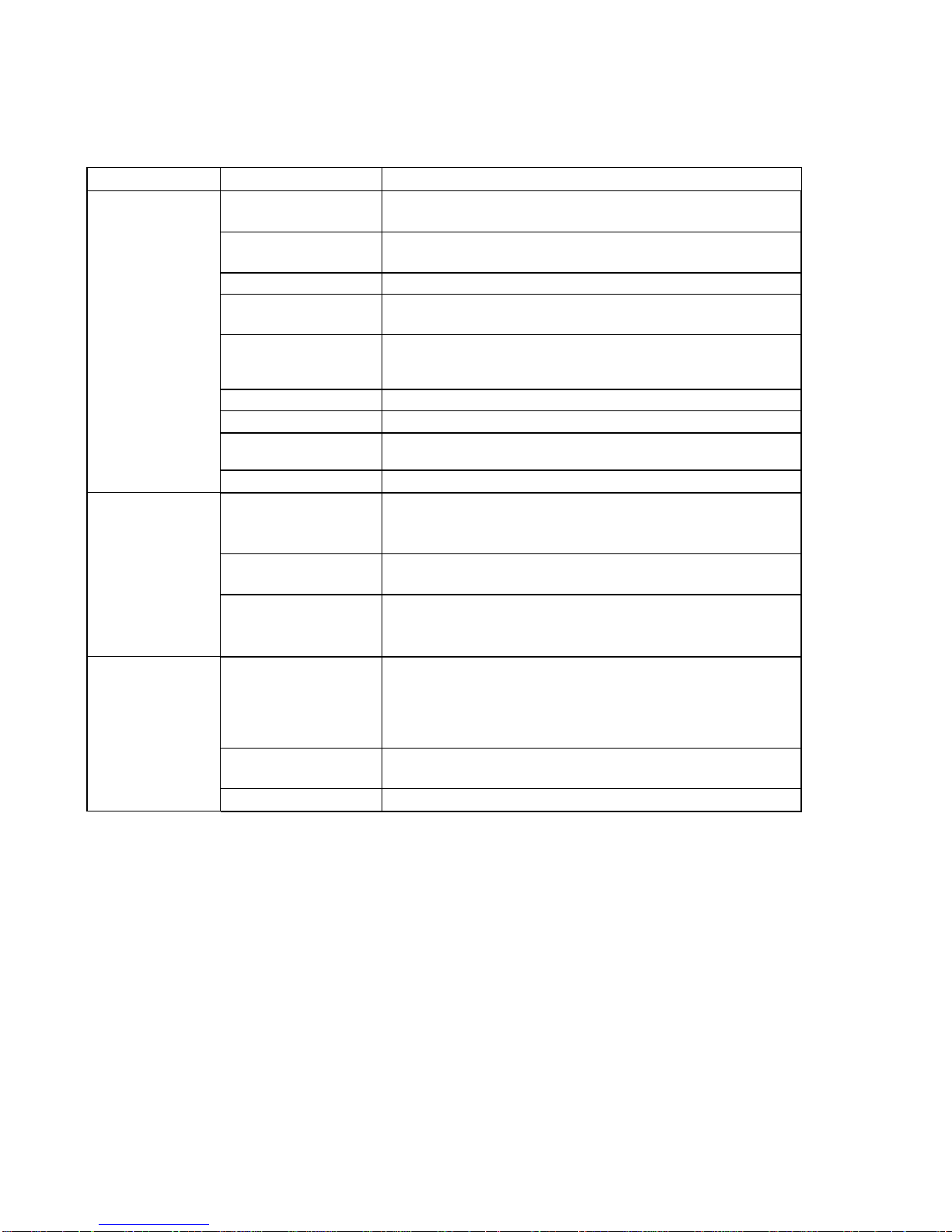
TROUBLESHOOTING
IMPORTANT: If trouble persists please call our customer help line at (877) 968-3733 M-F 8-5
Central Time.
Problem
Cause
Solution
Engine will not
start
Engine switch is set to
"off".
Set engine switch to "on".
Fuel valve is turned to
"closed".
Turn fuel valve to "open" position.
Choke is open.
Close the choke
Engine is out of gas.
Add gas.
Engine is filled with
contaminated or old
gas
Change the gas in the engine.
Spark plug is dirty.
Clean spark plug.
Spark plug is broken.
Replace spark plug.
Generator is not on
level surface.
Move generator to a level surface to prevent low oil
shutdown from triggering.
Oil is low
Add or replace oil.
Engine runs but
there is no
electrical output
Circuit Breaker button
is off.
Wait for 2 minutes and push the circuit breaker to the "on"
position.
Bad connecting
wires/cables.
If you are using an extension cord, try a different one.
Bad electrical device
connected
to generator.
Try connecting a different device.
Generator runs but
does not support
all electrical
devices
connected.
Generator
is overloaded
Perform these steps: 1. Turn off all electrical devices.
2. Unplug all electrical devices. 3. Turn off generator. 4. Wait
several minutes. 5. Restart genertor. 6.Try connecting fewer
electrical loads to the genertor.
Short in one of the
connected devices.
Try disconnecting any faulty or short -circuited electrical
loads.
Air cleaner is dirty.
Clean or replace air cleaner.
Page 29
29
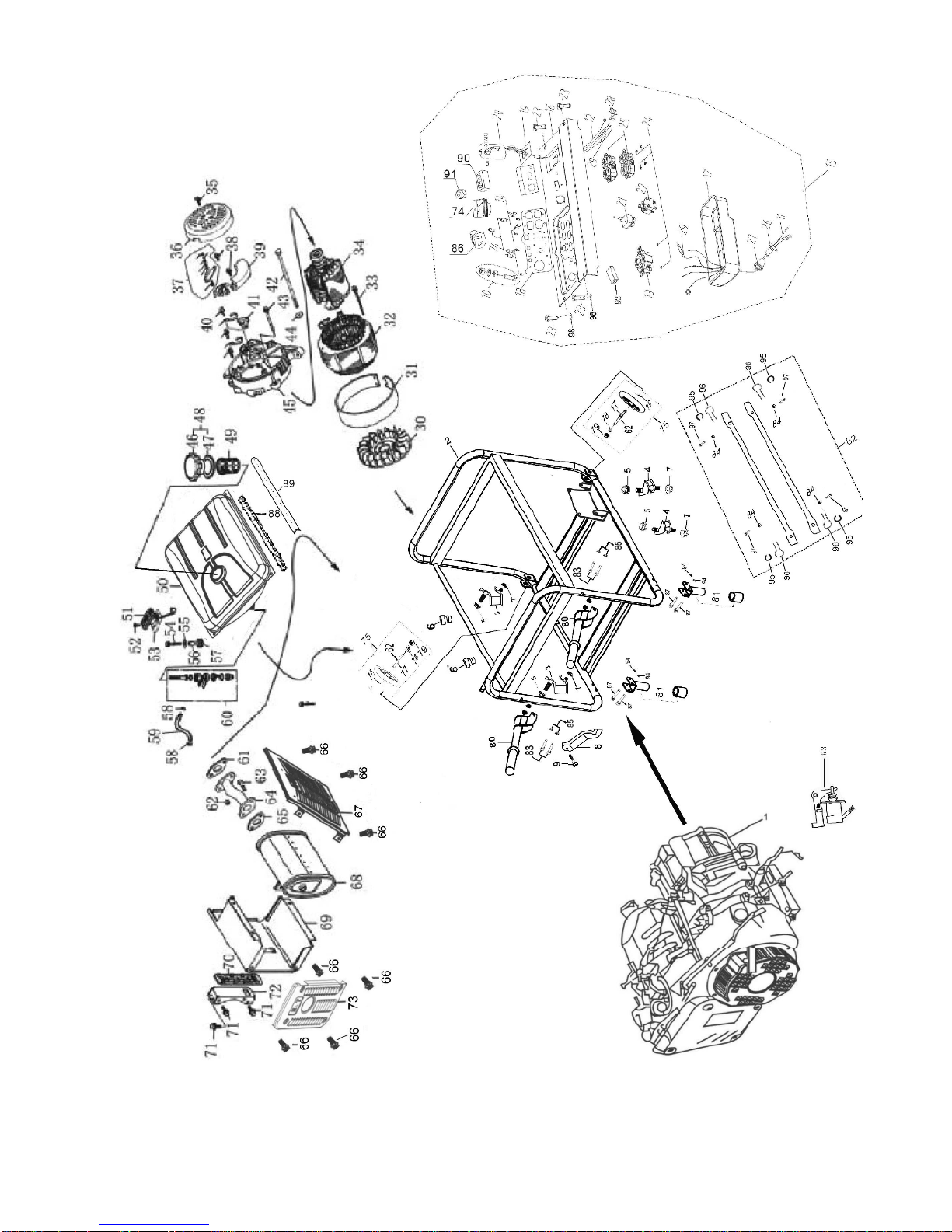
EXPLODED VIEW AND PARTS LIST
Page 30

30
PARTS LIST
Item
Description
Qty
Item
Description
Qty
1
13hp gasoline engine
150Gas tank
1
2
Tubular frame
151Fuel gauge
1
3
Left rubber damper
252Screw M5×10
2
4
Right rubber damper
253Gasket
1
5
Nut M10
454Bolt M6×25
4
6
Rubber frame pad
255Upper tank damper
4
7
Nut M8
456Bolt spacer
4
8
Air cleaner bracket
157Lower tank damper
4
9
M6×14 screw
158Fuel line clip
2
10
Earth terminal set
159Fuel line φ9×φ 4.5×170
1
11
Wire harness Assy
160Fuel valve assembly
1
12
Switch wire
161Exhaust pipe gasket
1
13
Consent(30A)
162Black gasket
2
14
Bolt M4×10
6638mm nut
2
15
Control panel Assy
164Exhaust pipe
1
16
Control panel
165Exhaust pipe gasket
1
17
Control panel case
1666×10 bolt
8
18
Panel switch mark,RH
167Muffler guard
1
19
Panel switch mark,LH
168Muffler
1
20
Ignition switch
169Muffler shroud
1
21
Voltage Selector
170Rubber seal
1
22
Circuit breaker(21A)
271Bolt M8× 16
4
23
Circuit bolt M6×25
472Metal bracket
1
24
Nut M4
673Muffler side cover
1
25
Duplex Receptacle
274Voltage Meter
1
26
Boot, AC output wire
475Wheel
2
27
Boot,main wire harness
1
76
Collar Pin
2
28
Diode Assy
2
77
Wheel Shaft
2
29
Fuse278
Spacer
2
30
Generator fan
1
79
Flange Nut
2
31
Stator cover
180Handle
2
32
Stator assy
181Rubber Foot
2
33
Bolt M5×198
282Protecting bar
2
34
Rotor183
Bolt M6X50
2
35
Screw M5×12
284Bolt
4
36
End cover
185Nut M6
2
37
Voltage change Terminal
18612V DC Receptacle
1
38
Screw M5×16
287Bolt M6X40
4
39
Capacitor assembly
188Stripe, fuel tank
1
40
Cable tie
189Decorating Stripe, fuel tank
1
41
Brush assembly
190Hours Meter
1
42
Bolt M10×250
191Low Oil Alert
1
43
Bolt M6×160
4
92
Current sensor inductors, idle speed
1
44
Washer
193Electromagnetic valve
1
45
Housing
194Nut M6
4
46
Gas cap
195Cushion
4
47
Gas cap washer
196Lock,protecting bar
4
48
Gas cap assembly
197Bolt M8X25
4
Page 31
31
Item
Description
Qty
Item
Description
Qty
49
Fuel tank filter
198Gasket,control pannel
4
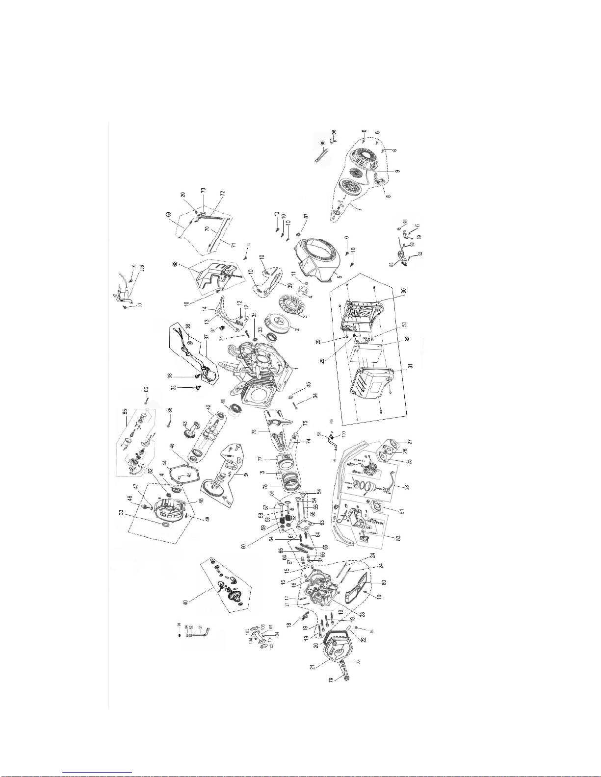
EXPLODED VIEW FOR ENGINE
Page 32

32
ENGINE PARTS LIST
NO.
Description
Qty
NO.
Description
Qty
1
Crankcase body
129M6 Nut
3
2
Flywheel assembly
130Air filter base
1
3
Cooling Fan
131Air filter cover
1
4
Starting Cup
132Air filter core assembly
1
5
Fan cover
133Sealing washer
2
6
M6X10 Bolt
434Bolt
2
7
Recoil starter cover
135Washer
2
8
Handle
136Nut
1
9
Recoil starting cord
137Oil sensor
1
10
M6X12 Bolt
1238M6X16 Bolt
2
11
M16X1.5 Nut
139Oil alert
1
12
M6X25 Bolt
240Regulating gear assembly
1
13
Choke cord
141Bearing 6207
2
14
lgnition winding assembly
142Crankshaft assembly
1
15
12*20 Pin
243Balance shaft
1
16
Cylinder gasket
144Crankcase cover gasket
1
17
M8X35 Bolt
2458X14 Pin
2
18
Spark plug F7TC
146Oil dipstick
1
19
M10X80 Bolt
447Seal
1
20
Cylinder cap gasket
148Crankcase cover
1
21
Cylinder cap assembly
149M8X40 Bolt
7
22
Exhaust air duct
150Camshaft assembly
1
23
Cylinder head assembly
151Regulating swing rod
1
24
M8/M6X110 Bolt
252Sealing washer
1
25
Intake gasket
153M5X16 Bolt
1
26
Heat insulation plate
154Tappet
2
27
Carburetor washer
155Handspike
2
28
Carburetor assembly
156Intake valve
1
57
Exhaust valve
182Bearing 6202
1
58
Oil baffle
183Check valve assembly
1
59
Spring
284Washer
1
60
Spring base
185Starting Motor
1
61
Rotor
186M8X32 Bolt
2
62
Spring base
187Rubber plug
1
63
Handspike guider
188Charge winding
1
64
Bolt289
Latch
1
65
Rocker
290Washer
1
66
Rocker shaft
291Rubber bushing
1
67
Adjusting nut
292M6X30 Bolt
2
68
Regulating bracket assembly
193B-spring
1
69
Restoring spring
194O-ring
1
70
Spring
195Wire lock
1
71
Regulating pull rod
196Plastic lock
1
72
Regulating arm
197Wire lock
1
73
T-Bolt
198Fuel pipe
1
74
Piston pin
199Duct lock
1
75
Locking washer
2
100
Lock bushing
1
76
Connecting rod assembly
1
101
Exhaust pipe
1
Page 33
33
NO.
Description
Qty
NO.
Description
Qty
77
Piston
1
102
Muffle washer
1
78
Piston ring assembly
1
103
Exhaust washer
1
79
M6X60 Bolt assembly
1
104
M8 Nut
2
80
Lower air baffle
1
105
Spring washer
2
81
Air filter gasket
1
106
Regulating electromagnetic valve
1
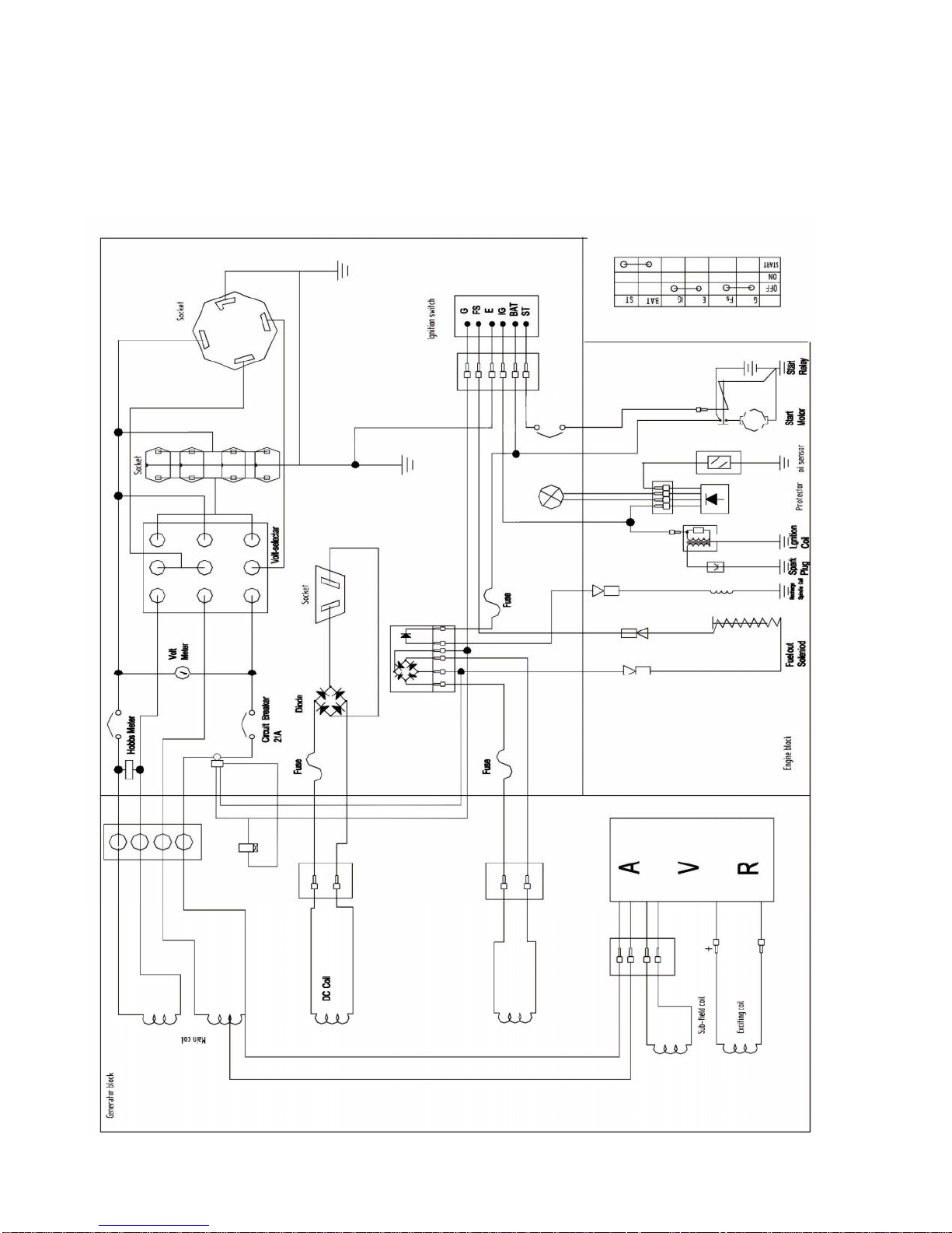
WIRING DIAGRAM
Page 34

34
NOTES:
Page 35

35
LIMITED WARRANTY FOR MULTI-POWER GENERATORS
Multi-Power Ltd. P O Box 396,Leoti, KS 67861. www.multipowerinc.com
Remember to save your receipt and to accurately fill out and mail your product regis tration
card. You must provide proof of purchase for all warranty work.
Multi-Power generators are warranted to be free from defects in materials and workmanship for a
period of one (1) year from date of original purchase. Generators used for Commercial o r Rental
use have a warranty period of 90 days from date of original purchase. Keep purchase receipt and
mail in the product registration card for proof of purchase.
Multi-Power will repair or replace, at its discretion, any part that is proven to be defe ctive in
materials or workmanship under normal use during the one (1) year warranty period. Warranty
repairs or replacements will be made without charge for parts or labor. Parts replaced during
warranty repairs will be considered as part of the original p roduct and will have the same
warranty period as the original product.
To exercise the warranty, DO NOT RETURN TO RETAILER . Instead, call the toll free
Customer Service number: (877) 968-3733 and you will be instructed on where to take the
generator for warranty service. Take the generator and proof of purchase (your receipt) to the
repair facility recommended by the Customer Service Representative.
All transportation costs under warranty, including return to the factory if necessary, are to be
borne by the purchaser and prepaid by the purchaser. The term “purchaser” means the person for
whom the generator is originally purchased. This warranty is non -transferable.
The warranty does not extend to generators damaged or affected by fuel contamination,
accidents, neglect, misuse, unauthorized alterations, use in an application for which the product
was not designed and any other modifications or abuse.
Multi-Power is not liable for any indirect, incidental or consequential damages from the sale or
use of this product. Any implied warranties are limited to one (1) year as stated in this written
limited warranty. Some states do not allow the exclusion or limitation of incidental or
consequential damages. Some states do not allow limitation on the length of an implied warranty.
This warranty gives you specific legal rights, and you may have other rights that vary from state
to state.
 Loading...