

Page 1
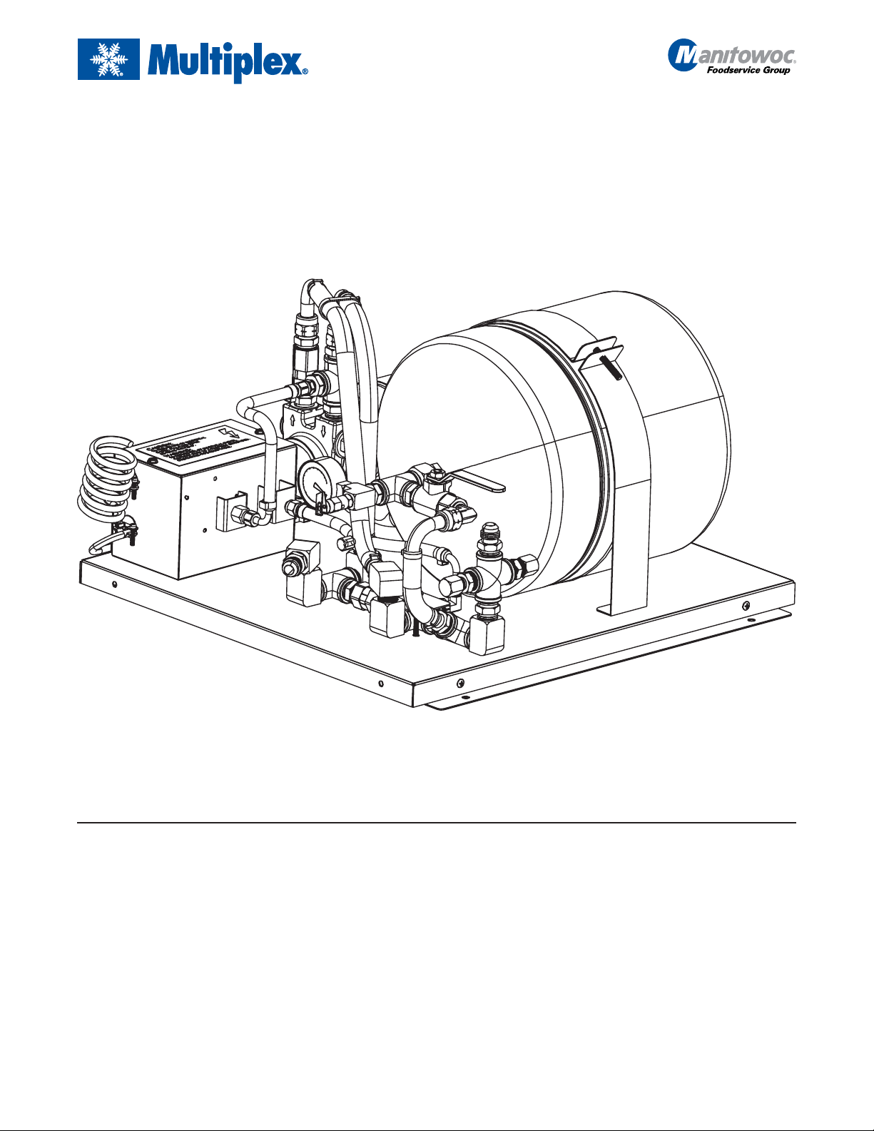
Multiplex Beverage Equipment Installation Instructions for
Model WBK10 and WBK10X Water Booster Pump
P.N. 00215639 (120 VAC, 60 Hz) and
P.N. 00216382 (220 VAC, 50 Hz)
Table of Contents
Caution: To Avoid Serious Injury ............................... 2
Introduction ....................................................... 3
Preparing the power cord (international units only
[P.N. 00216382]) ............................................ 3
Grounding instructions........................................... 3
Manitowoc Beverage Equipment
2100 Future Drive Sellersburg, IN 47172-1868
Tel: 812.246.7000, 800.367.4233 Fax: 812.246.9922
www.manitowocbeverage.com
Installing the Multiplex Model WBK10/WBK10X
Water Booster Pump ............................................. 4
How to install the water booster pump to wall.......... 4
How to install the water booster pump to a
support stand ................................................. 5
Before installing the water booster pump................ 6
After installing the water booster pump.................. 6
In accordance with our policy of continuous product development and improvement,
this information is subject to change at any time without notice.
EI215639 June 02, 2008
Page 2
Equipment Installation Instructions
Caution: To Avoid Serious Injury
Important: Read the following warnings before beginning an installation. Failure to do so
may result in possible death or serious injury.
DO Adhere to all National and Local Plumbing and Electrical Safety Codes.
DO Turn “off” incoming electrical service switches when servicing, installing, or
repairing equipment.
DO Check that all flare fittings on the carbonation tank(s) are tight. This check
should be performed with a wrench to ensure a quality seal.
DO Inspect pressure on Regulators before starting up equipment.
DO Protect eyes when working around refrigerants.
DO Use caution when handling metal surface edges of all equipment.
DO Handle CO
2 cylinders and gauges with care. Secure cylinders properly against
abrasion.
DO Store CO2 cylinder(s) in well ventilated areas.
DO NOT Throw or drop a CO2 cylinder. Secure the cylinder(s) in an upright position
with a chain.
DO NOT Connect the CO2 cylinder(s) directly to the product container. Doing so will
result in an explosion causing possible death or injury. Best to connect the
CO2 cylinder(s) to a regulator(s).
DO NOT Store CO2 cylinders in temperature above 125°F (51.7°C) near furnaces,
radiator or sources of heat.
DO NOT Release CO2 gas from old cylinder.
DO NOT Touch Refrigeration lines inside units, some may exceed temperatures of
200°F (93.3°C).
Notice: Water pipe connections and fixtures directly connected to a potable water supply
shall be sized, installed and maintained in accordance with Federal, State, and Local codes.
2
EI215639 June 02, 2008
Page 3

Equipment Installation Instructions
Introduction
The following instructions cover the installation of a 120 VAC, 60 Hz (domestic) and 220 VAC, 50 Hz (international). An
appropriate 3-Wire power receptacle must be located within 6 ft (1.8 m) of the Booster Kits.
Note: Do not plug in Booster Pump Module at this time.
Preparing the power cord (international units only [P.N. 00216382])
1. Locate a 3 terminal plug. This plug (not furnished with kit) must have a ground-wire-connecting terminal.
1
2. Locate the loose end of the power cord attached to the kit. All three (3) wires are stripped to
1
3. Connect all three (3) wires to the plug using the
terminals may require different stripped lengths.
4. Inspect the cord and plug connection for any loose or bare wires.
/2" stripped ends or any other terminal requirements. Different plugs and
/2" length from the end.
Grounding instructions
The Multiplex Model WBK10/WBK10X Water Booster Pump should be grounded. In the event of an electrical short circuit,
grounding reduces the risk of electric shock by providing an escape wire for the electrical current. This product is equipped
with a cord having a grounding wire with an appropriate grounding plug. The plug must be plugged into an outlet that is
properly installed and grounded in accordance with all local codes and ordinances.
WARNING! RISK OF ELECTRIC SHOCK: This kit is supplied with a ground conductor and grounding-type attachment plug
(domestic only). To reduce the risk of electric shock, be certain that it is connected only to a properly grounded, groundingtype receptacle.
Note: For 220 V AC, 50 Hz International Units, a ground male plug must be supplied at the installation of the booster pump.
Check with a qualified electrician or serviceman if the grounding instructions are not completely understood, or if in doubt
as to whether the product is properly grounded. Do not modify the plug provided; if it will not fit the outlet, have the proper
outlet installed by a qualified electrician.
This product is for use with a 120 VAC, 60 Hz (Domestic) or 220 VAC, 50 Hz (International). CSA requires that a switch be
provided to disconnect both outlets from the power supply (refer to figure 1).
Do not use an extension cord or an adaptor plug with this equipment.
EI215639 June 02, 2008
Figure 1
3
Page 4

Installing the Multiplex Model WBK10/WBK10X
Water Booster Pump
Equipment Installation Instructions
How to install the water booster
pump to wall
1. Locate the six (6) 5/16" lag screws and the mounting
bracket.
2. Mount the J-channel to the wall using three (3) screws
(provided).
Note: Screws must be located in a stud. If mounting to concrete wall, proper hardware (not provided) must be used.
3. Mount the booster Panel on the wall by raising the top of
the panel over the J-channel. Place the panel against wall
and slide the panel down until is catches on the J-channel.
Mount the bottom of the panel to the wall using the remaining two (2) screws (refer to figure 2).
J-channel Mounting
Bracket
4. Attach a 1/2" ID water inlet line to the inlet fitting labeled
#27 using the Barb stem, nut, and clamp provided. Then
attach another
#28 using the remaining Barb stem, nut, and clamp (refer
to figure 2).
5. Turn “on” the main water supply to the booster assembly.
Note: Outlet pressure of this assembly is not regulated.
A regulator may be required for certain applications.
6. Plug the power cord into the wall receptacle. The pump
will not begin to run until low water pressure circuit times
out. When the pump cycles “off”, the gauge should read
85 psi (59 bar). Bleed off water flow until pressure drops
to approximately 65 psi (4.5 bar). The pump motor should
begin to run, then turn “off” when pressure reaches 85 psi
(5.9 bar). If not, there are instructions on the inside of
the pressure switch cover for pressure switch adjustment.
1
/2" ID line to the Water Outlet labeled
Mounting
Wall
Power Cord
#27 Water Inlet
(1/2" Male Flare)
#28 Water Outlet
1
/2" Male Flare)
(
Mounting Screws
Figure 2
4
Water Booster
Pump
EI215639 June 02, 2008
Page 5

Equipment Installation Instructions
Installing the Multiplex Model WBK10/WBK10X
Water Booster Pump
(continued)
How to install the water booster
pump to a support stand
Note: This W ater Booster Pump can either be mounted to the
side or on the inside of the support stand. The method of
mounting is the same for either application. The following
instructions cover the side mounting. This stand is factory
assembled to mount the Water Booster Pump on the left-hand
side of the support stand. However, the W ater Booster can be
mounted on the right-hand side by moving the channel to
that side.
Caution: If the system has a plate Style W ater Filter, it MUST
be mounted to the right-hand side.
1. Locate the mounting hardware supplied with the support
stand: three (3)
x 1/2" Hex screws (not supplied), five (5) 1/4"-20 locking
nuts, and the J-Channel Mounting Plate, (supplied with
the Water Booster). The J-channel Mounting Plate will later
be mounted to the Water Booster Pump.
J-channel Mounting
Bracket
1
/4"-20 x 1/2" Carriage Bolts, two (2) 1/4"-20
2. With the hook end of the J-channel towards the floor,
mount the channel to the top portion on the side of the
stand.
1
3. Fasten the channel with three (3)
bolts and
4. Lifting the back edge of the panel above the channel and
hooking it on the lower edge of the J-channel, place the
Water Booster Pump panel on the J-channel.
5. Attach the lower edge of the Water Booster Pump panel
to the channel on the support stand with two (2)
1
/2" Hex screws and 1/4"-20 locking nuts. Tighten the screws
and nuts completely.
6. Complete the remaining installation using the instructions
supplied with the Water Booster Pump.
1
/4"-20 locking nuts. Tighten all bolts completely.
/4"-20 x 1/2" Carriage
1
/4"-20 x
Model WBK10/WBK10X
Water Booster Pump
Mounting screws and
nuts (supplied with
the support stand)
EI215639 June 02, 2008
Multiplex Support
Stand
Figure 3
5
Page 6

Installing the Multiplex Model WBK10/WBK10X
Water Booster Pump (continued)
Before installing the water booster pump
Equipment Installation Instructions
After installing the water booster pump
Figure 3
6
EI215639 June 02, 2008
 Loading...