

Page 1
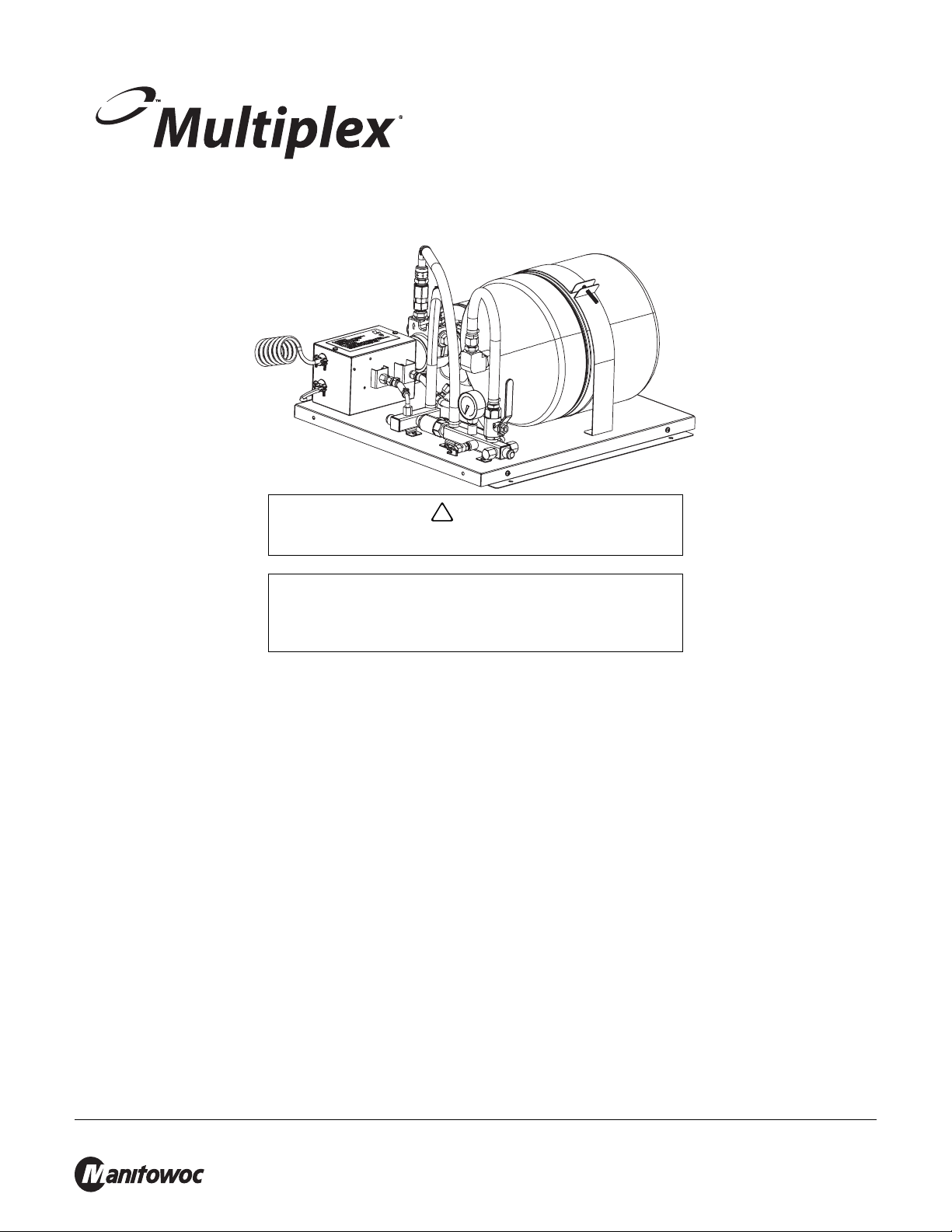
Subject: Model WBK10X Water Booster Pump
!
Caution
Important
P.N. 00216382 (220-240 VAC, 50/60 HZ)
020006830
9/15
Instructions
Caution: To Avoid Serious Injury
Read the following warnings before beginning an installation. Failure
to do so may result in possible death or serious injury.
DO Adhere to all National and Local Plumbing and Electrical Safety Codes.
DO Turn “off” incoming electrical service switches when servicing, installing, or repairing equipment.
DO Check that all flare fittings on the carbonation tank(s) are tight. This check should be performed with a
wrench to ensure a quality seal.
DO Inspect pressure on Regulators before starting up equipment.
DO Protect eyes when working around refrigerants.
DO Use caution when handling metal surface edges of all equipment.
DO Handle CO2 cylinders and gauges with care. Secure cylinders properly against abrasion.
DO Store CO2 cylinder(s) in well ventilated areas.
DO NOT Throw or drop a CO2 cylinder. Secure the cylinder(s) in an upright position with a chain.
DO NOT Connect the CO2 cylinder(s) directly to the product container. Doing so will result in an explosion
causing possible death or injury. Best to connect the CO2 cylinder(s) to a regulator(s).
DO NOT Store CO2 cylinders in temperature above 125°F (51.7°C) near furnaces, radiator or sources of heat.
DO NOT Release CO2 gas from old cylinder.
DO NOT Touch Refrigeration lines inside units, some may exceed temperatures of 200°F (93.3°C).
NOTE: Water pipe connections and fixtures directly connected to a potable water supply shall be sized, installed and
maintained in accordance with Federal, State, and Local codes.
Manitowoc Foodservice, 2110 S. 26th St., P.O. Box 1720, Manitowoc, WI 54221-1720, Tel: 920-682-0161, www.manitowocfsg.com
Page 2
Model WBK10X Water Booster Pump 020006830 9/15
!
Warning
!
Warning
!
Warning
Disconnect and lock out all electrical power sources before performing
service or maintenance on this machine - - except when electrical tests are
being performed by qualified service personnel.
The appliance is not to be used by persons (including children) with
reduced physical, sensory or mental capabilities, or lack of experience and
knowledge, unless they have been given supervision or instruction.
Children must be supervised and are not to play with the appliance.
Attention: Pressure Requirements
Max. inlet water pressure (Pa): 0.345 Mpa (3.45 bar) (50 psi)
Min. inlet water pressure (Pa): 0.138 Mpa (1.38 bar) (20 psi)
Introduction
The following instructions cover the installation of a 220 VAC, 50/60 Hz (international) booster. An appropriate 3-Wire
power receptacle must be located within 6 ft (1.8 m) of the Booster Kits.
NOTE: Do not plug in Booster Pump Module at this time.
Preparing the power cord (international units only [P.N. 00216382])
1. Locate a 3 terminal plug. This plug (not furnished with kit) must have a ground-wire-connecting terminal.
2. Locate the loose end of the power cord attached to the kit. All three (3) wires are stripped to 1/2” (2.5 cm) length from the
end.
3. Connect all three (3) wires to the plug using the 1/2” (2.5 cm) stripped ends or any other terminal requirements. Different
plugs and terminals may require different stripped lengths.
4. Inspect the cord and plug connection for any loose or bare wires.
Grounding instructions
The Multiplex Model WBK10X Water Booster Pump should be grounded. In the event of an electrical short circuit,
grounding reduces the risk of electric shock by providing an escape wire for the electrical current. This product is
equipped with a cord having a grounding wire with an appropriate grounding plug. The plug must be plugged into an
outlet that is properly installed and grounded in accordance with all local codes and ordinances.
RISK OF ELECTRIC SHOCK: This kit is supplied with a ground
conductor and grounding-type attachment plug (domestic only). To
reduce the risk of electric shock, be certain that it is connected only
to a properly grounded, grounding-type receptacle.
NOTE: For 220-240 VAC, 50/60 Hz International Units, a ground male plug must be supplied at the installation of the
booster pump.
Check with a qualified electrician or serviceman if the grounding instructions are not completely understood, or if in doubt as to
whether the product is properly grounded. Do not modify the plug provided; if it will not fit the outlet, have the proper outlet
installed by a qualified electrician.
Manitowoc Foodservice Group, 2110 S. 26th St., P.O. Box 1720, Manitowoc, WI 54221-1720, Tel: 920-682-0161, www.manitowocfsg.com
Page 3

Model WBK10X Water Booster Pump 020006830 9/15
Important
FIG 1
Do not use an extension cord or an adapter plug with this equipment.
Installation
This booster pump is intended to be installed outside
zone 1 and 2, as specified in IEC 60364-7-701.
The booster pump needs to be installed with a
horizontal distance to possibly spraying water of 1.8
meter. It is not allowed to install the water booster
above or below (vertically) of possibly spraying water
sources.
The water booster has to be installed vertical and NOT
horizontal.
HOW TO INSTALL THE WATER BOOSTER PUMP TO A WALL
1. Locate the six (6) 5/16” lag screws and the mounting bracket.
2. Mount the J-channel to the wall using three (3) screws (provided).
NOTE: Screws must be located in a stud. If mounting to concrete wall, proper hardware (not provided) must be used.
3. Place the Booster Splash Guard on edge of the booster panel that has the three (3) mounting holes. Use three (3) 8-32 x
1/2” self tapping screws supplied with the booster to mount the guard to the panel.
4. Mount the booster Panel on the wall by raising the top of the panel over the J-channel. Place the panel against wall and
slide the panel down until is catches on the J-channel. Mount the bottom of the panel to the wall using the remaining two
(2) screws (refer to figure 2).
5. Attach a 1/2” ID water inlet line to the inlet fitting using the 1/2” flare elbow with nut, and clamp provided. Then attach
another 1/2” ID line to the Water Outlet using the remaining 1/2” flare elbow with nut, and clamp (refer to figure 2).
6. Turn “on” the main water supply to the booster assembly.
NOTE: Outlet pressure of this assembly is not regulated. A regulator may be required for certain applications.
Manitowoc Foodservice Group, 2110 S. 26th St., P.O. Box 1720, Manitowoc, WI 54221-1720, Tel: 920-682-0161, www.manitowocfsg.com
Page 4

Model WBK10X Water Booster Pump 020006830 9/15
FIG 2
Mounting
Wall
J- Channel
Mounting Bracket
Water
Booster
Pump
Mounting Screws
#28 Water Outlet
(1/2” Male Flare)
#27 Water Inlet
(1/2” Male Flare)
Power Cord
Booster Splash
Guard
7. Plug the power cord into the wall receptacle. The pump will not begin to run until low water pressure circuit times out.
When the pump cycles “off”, the gauge should read .586 Mpa (5.86 bar) (85 psi). Bleed off water flow until pressure
drops to approximately .448 Mpa (4.48 bar) (65 psi). The pump motor should begin to run, then turn “off” when pressure
reaches .586 Mpa (5.86 bar) (85 psi). If not, there are instructions on the inside of the pressure switch cover for pressure
switch adjustment.
Manitowoc Foodservice Group, 2110 S. 26th St., P.O. Box 1720, Manitowoc, WI 54221-1720, Tel: 920-682-0161, www.manitowocfsg.com
Page 5

Model WBK10X Water Booster Pump 020006830 9/15
!
Caution
FIG 3
Multiplex
Support
Stand
J-Channel
Mounting
Bracket
Model WBK10X
Water Booster
Pump
Mounting
Screws & Nuts
(supplied with
support stand)
Booster
Splash Guard
How to install the water booster pump to a support stand
NOTE: This Water Booster Pump can either be mounted to the side or on the inside of the support stand. The method
of mounting is the same for either application. The following instructions cover the side mounting. This stand is factory
assembled to mount the Water Booster Pump on the left-hand side of the support stand. However, the Water Booster
can be mounted on the right-hand side by moving the channel to that side.
If the system has a plate Style Water Filter, it MUST be mounted to
the right-hand side.
1. Locate the mounting hardware supplied with the support stand: three (3) 1/4”-20 x 1/2” Carriage Bolts, two (2) 1/4”-20 x 1/
2” Hex screws (not supplied), five (5) 1/4”-20 locking nuts, and the J-Channel Mounting Plate, (supplied with the Water
Booster). The J-channel Mounting Plate will later be mounted to the Water Booster Pump.
2. With the hook end of the J-channel towards the floor, mount the channel to the top portion on the side of the stand.
3. Fasten the channel with three (3) 1/4”-20 x 1/2” Carriage bolts and 1/4”-20 locking nuts. Tighten all bolts completely.
4. Place the Booster Splash Guard on edge of the booster panel that has the three (3) mounting holes. Use three (3) 8-32 x
1/2” self tapping screws supplied with the booster to mount the guard to the panel.
5. Lifting the back edge of the panel above the channel and hooking it on the lower edge of the J-channel, place the Water
Booster Pump panel on the J-channel.
6. Attach the lower edge of the Water Booster Pump panel to the channel on the support stand with two (2) 1/4”-20 x 1/2”
Hex screws and 1/4”-20 locking nuts. Tighten the screws and nuts completely.
7. Complete the remaining installation using the instructions supplied with the Water Booster Pump.
Manitowoc Foodservice Group, 2110 S. 26th St., P.O. Box 1720, Manitowoc, WI 54221-1720, Tel: 920-682-0161, www.manitowocfsg.com
Page 6

Model WBK10X Water Booster Pump 020006830 9/15
Incoming
Water
Supply
Coarse
Filter
Filter
Accumulator Tank (optional)
Beverage Unit
To Dispenser
Regulator
.379 Mpa (3.79 bar)
(55 psi)
FIG 4
Incoming
Water
Supply
Accumulator Tank (optional)
Beverage Unit
To Dispenser
Regulator
.379 Mpa (3.79 bar)
(55 psi)
Coarse
Filter
Filter
Water
Booster
Pump
Before installing the water booster pump
After installing the water booster pump
OPERATION
Manitowoc Foodservice Group, 2110 S. 26th St., P.O. Box 1720, Manitowoc, WI 54221-1720, Tel: 920-682-0161, www.manitowocfsg.com
1. Before applying supply water pressure, verify with air gauge, that the bladder pressure (Schrader valve) is
charged to .414 Mpa (4.14 bar) (60 psi) PSI.
2. Turn water supply ON, then plug unit into supply power outlet.
3. Verify unit pump comes ON and pumps up to .586 Mpa (5.86 bar) (85 psi) and then pump goes OFF.
4. Verify unit pump comes on at .448 Mpa (4.48 bar) (65 psi), by expelling water from system.
 Loading...