

Page 1
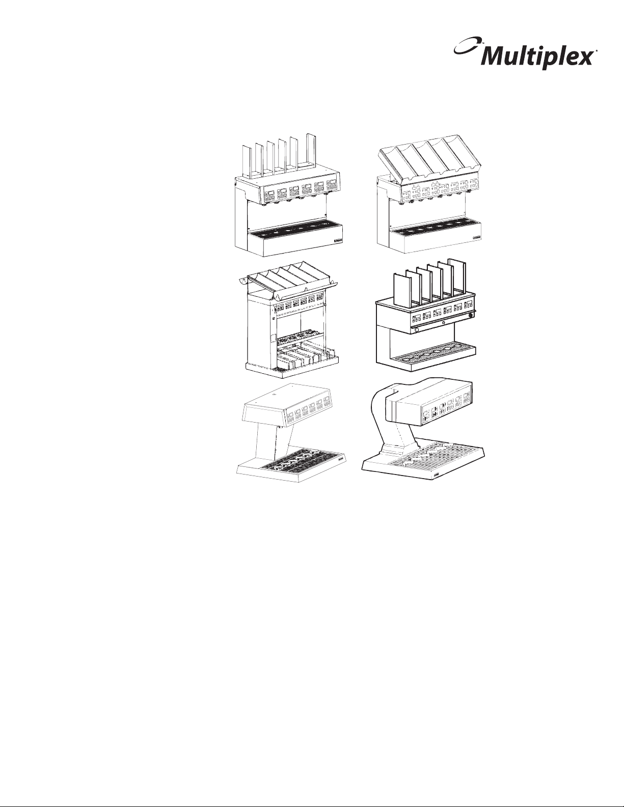
Soda Dispensing Towers
Installation, Use & Care Manual
This manual is updated as new information and models are released.
Visit our website for the latest manual. www.manitowocfsg.com
America’s Quality Choice in Refrigeration
Part Number 020002777 10/11
Page 2
Safety Notices
!
Warning
!
Caution
Important
!
Caution
Important
!
Warning
As you work on Manitowoc equipment, be sure to pay
close attention to the safety notices in this manual.
Disregarding the notices may lead to serious injury and/
or damage to the equipment.
Throughout this manual, you will see the following types
of safety notices:
Text in a Warning box alerts you to a potential
personal injury situation. Be sure to read the
Warning statement before proceeding, and work
carefully.
Text in a Caution box alerts you to a situation in
which you could damage the equip ment. Be sure to
read the Caution statement before proceeding, and
work carefully.
Procedural Notices
As you work on Manitowoc equipment, be sure to read
the procedural notices in this manual. These notices
supply helpful information which may assist you as you
work.
Throughout this manual, you will see the following types
of procedural notices:
Read These Before Proceeding:
Proper installation, care and maintenance are
essential for maximum performance and trouble-free
operation of your Manitowoc equipment. Read and
understand this manual. It contains valuable care
and maintenance information. If you encounter
problems not covered by this manual, do not
proceed, contact Manitowoc. We will be happy to
provide assistance.
Routine adjustments and maintenance procedures
outlined in this manual are not covered by the
warranty.
PERSONAL INJURY POTENTIAL
Do not operate equipment that has been misused,
abused, neglected, damaged, or altered/modified
from that of original manufactured specifications.
NOTE: SAVE THESE INSTRUCTIONS.
Text in an Important box provides you with
information that may help you perform a procedure
more efficiently. Disregarding this information will not
cause damage or injury, but it may slow you down as
you work.
NOTE: Text set off as a Note provides you with simple,
but useful, extra information about th e pr oce dur e yo u
are performing.
We reserve the right to make product improvements at any time.
Specifications and design are subject to change without notice.
Page 3

We reserve the right to make product improvements at any time.
THIS PAGE INTENTIONALLY LEFT BLANK
Specifications and design are subject to change without notice.
Page 4

We reserve the right to make product improvements at any time.
Specifications and design are subject to change without notice.
Page 5

Section 1
General Information
Section 2
Installation
Table of Contents
Read This Manual. . . . . . . . . . . . . . . . . . . . . . . . . . . . . . . . . . . . . . . . . . . . . . . . . 1-1
Unit Inspection . . . . . . . . . . . . . . . . . . . . . . . . . . . . . . . . . . . . . . . . . . . . . . . . . . . 1-1
Model Numbers. . . . . . . . . . . . . . . . . . . . . . . . . . . . . . . . . . . . . . . . . . . . . . . . . . . 1-1
Attention: Marine Installations . . . . . . . . . . . . . . . . . . . . . . . . . . . . . . . . . . . 1-2
Outdoor Applications . . . . . . . . . . . . . . . . . . . . . . . . . . . . . . . . . . . . . . . . . . 1-2
Serial Plate Location . . . . . . . . . . . . . . . . . . . . . . . . . . . . . . . . . . . . . . . . . . . . . . 1-2
Warranty Information . . . . . . . . . . . . . . . . . . . . . . . . . . . . . . . . . . . . . . . . . . . . . . 1-2
Dimensions and Clearances — All Models . . . . . . . . . . . . . . . . . . . . . . . . . . . . 2-1
Model 116 . . . . . . . . . . . . . . . . . . . . . . . . . . . . . . . . . . . . . . . . . . . . . . . . . . 2-1
Model 126 (V-Style) . . . . . . . . . . . . . . . . . . . . . . . . . . . . . . . . . . . . . . . . . . 2-1
Model 136 . . . . . . . . . . . . . . . . . . . . . . . . . . . . . . . . . . . . . . . . . . . . . . . . . . 2-1
Model 126 (S-Style) . . . . . . . . . . . . . . . . . . . . . . . . . . . . . . . . . . . . . . . . . . 2-1
Model 138 . . . . . . . . . . . . . . . . . . . . . . . . . . . . . . . . . . . . . . . . . . . . . . . . . . 2-2
Model 143 . . . . . . . . . . . . . . . . . . . . . . . . . . . . . . . . . . . . . . . . . . . . . . . . . . 2-2
Model 158 . . . . . . . . . . . . . . . . . . . . . . . . . . . . . . . . . . . . . . . . . . . . . . . . . . 2-2
Model 156 . . . . . . . . . . . . . . . . . . . . . . . . . . . . . . . . . . . . . . . . . . . . . . . . . . 2-2
Model 158 (High Cup Clearance) . . . . . . . . . . . . . . . . . . . . . . . . . . . . . . . . 2-3
Model 1310 (With Drain Pan) . . . . . . . . . . . . . . . . . . . . . . . . . . . . . . . . . . . 2-3
Model 1310 (No Drain Pan) . . . . . . . . . . . . . . . . . . . . . . . . . . . . . . . . . . . . 2-3
FootPrints - All Models . . . . . . . . . . . . . . . . . . . . . . . . . . . . . . . . . . . . . . . . 2-4
Model 116 . . . . . . . . . . . . . . . . . . . . . . . . . . . . . . . . . . . . . . . . . . . . . . . . . . 2-4
Model 126 (V & S-Style Towers) . . . . . . . . . . . . . . . . . . . . . . . . . . . . . . . . . 2-4
Model 136 . . . . . . . . . . . . . . . . . . . . . . . . . . . . . . . . . . . . . . . . . . . . . . . . . . 2-5
Model 138 . . . . . . . . . . . . . . . . . . . . . . . . . . . . . . . . . . . . . . . . . . . . . . . . . . 2-5
Model 143 . . . . . . . . . . . . . . . . . . . . . . . . . . . . . . . . . . . . . . . . . . . . . . . . . . 2-6
Model 156 (Left Hand Pass-Thru) . . . . . . . . . . . . . . . . . . . . . . . . . . . . . . . . 2-7
Model 156 (Right Hand Pass-Thru) . . . . . . . . . . . . . . . . . . . . . . . . . . . . . . 2-7
Model 158 . . . . . . . . . . . . . . . . . . . . . . . . . . . . . . . . . . . . . . . . . . . . . . . . . . 2-8
Model 1310 . . . . . . . . . . . . . . . . . . . . . . . . . . . . . . . . . . . . . . . . . . . . . . . . . 2-9
Safe Installation Dos and Don’ts. . . . . . . . . . . . . . . . . . . . . . . . . . . . . . . . . . . . . 2-10
Part Number 020002777 10/11 i
Page 6

Table of Contents (continued)
Location Requirements . . . . . . . . . . . . . . . . . . . . . . . . . . . . . . . . . . . . . . . . . . . . 2-10
Location of the Dispensing Tower . . . . . . . . . . . . . . . . . . . . . . . . . . . . . . . . 2-10
Ratings . . . . . . . . . . . . . . . . . . . . . . . . . . . . . . . . . . . . . . . . . . . . . . . . . . . . 2-10
Kitchen Equipment Installer Representative Responsibilities . . . . . . . . . . . 2-10
Requirements . . . . . . . . . . . . . . . . . . . . . . . . . . . . . . . . . . . . . . . . . . . . . . . 2-11
Installer Instructions. . . . . . . . . . . . . . . . . . . . . . . . . . . . . . . . . . . . . . . . . . . . . . . 2-11
Preparation . . . . . . . . . . . . . . . . . . . . . . . . . . . . . . . . . . . . . . . . . . . . . . . . . 2-11
Electrical . . . . . . . . . . . . . . . . . . . . . . . . . . . . . . . . . . . . . . . . . . . . . . . . . . . . . . . . 2-11
General . . . . . . . . . . . . . . . . . . . . . . . . . . . . . . . . . . . . . . . . . . . . . . . . . . . . 2-11
Minimum Circuit Ampacity . . . . . . . . . . . . . . . . . . . . . . . . . . . . . . . . . . . . . . 2-11
Electrical Requirements . . . . . . . . . . . . . . . . . . . . . . . . . . . . . . . . . . . . . . . . 2-11
Electrical Specifications . . . . . . . . . . . . . . . . . . . . . . . . . . . . . . . . . . . . . . . . 2-11
Making the Electrical Connections . . . . . . . . . . . . . . . . . . . . . . . . . . . . . . . 2-11
Grounding Instructions . . . . . . . . . . . . . . . . . . . . . . . . . . . . . . . . . . . . . . . . 2-12
Mounting The Dispensing Tower. . . . . . . . . . . . . . . . . . . . . . . . . . . . . . . . . . . . . 2-13
Secured By Bolting To The Counter . . . . . . . . . . . . . . . . . . . . . . . . . . . . . . 2-13
Secured With Mounting Clamps . . . . . . . . . . . . . . . . . . . . . . . . . . . . . . . . . 2-13
Plumbing – General. . . . . . . . . . . . . . . . . . . . . . . . . . . . . . . . . . . . . . . . . . . . . . . . 2-14
Connecting The Syrup And Water Lines . . . . . . . . . . . . . . . . . . . . . . . . . . . 2-14
How to Insulate all the Connections . . . . . . . . . . . . . . . . . . . . . . . . . . . . . . . . . . 2-18
Section 3
Operation
Calibration of the Dispensing Valves . . . . . . . . . . . . . . . . . . . . . . . . . . . . . . . . . 3-1
Set The Flow (Water Flow Rate Only) . . . . . . . . . . . . . . . . . . . . . . . . . . . . . 3-1
Set The Ratio (Water To Syrup Mixture) . . . . . . . . . . . . . . . . . . . . . . . . . . . 3-2
Set The Volume (Drink Portion Sizes) . . . . . . . . . . . . . . . . . . . . . . . . . . . . . 3-2
Run mode . . . . . . . . . . . . . . . . . . . . . . . . . . . . . . . . . . . . . . . . . . . . . . . . . . 3-2
Program modes. . . . . . . . . . . . . . . . . . . . . . . . . . . . . . . . . . . . . . . . . . . . . . . . . . . 3-3
Program Mode CAL No. 1 (total volume) . . . . . . . . . . . . . . . . . . . . . . . . . . 3-3
Program Mode CAL No. 2 (incremental) . . . . . . . . . . . . . . . . . . . . . . . . . . . 3-3
Program Mode CAL No. 3 (Water/Soda) . . . . . . . . . . . . . . . . . . . . . . . . . . . 3-3
Top-off program mode . . . . . . . . . . . . . . . . . . . . . . . . . . . . . . . . . . . . . . . . . 3-4
Test And Sanitation Mode . . . . . . . . . . . . . . . . . . . . . . . . . . . . . . . . . . . . . . 3-4
Instructions For Dual Flavor Stations . . . . . . . . . . . . . . . . . . . . . . . . . . . . . 3-4
Entering Water/soda Programming Mode . . . . . . . . . . . . . . . . . . . . . . . . . . 3-4
Equipment Setup and Close Procedure . . . . . . . . . . . . . . . . . . . . . . . . . . . . . . . 3-4
Equipment Setup Procedure . . . . . . . . . . . . . . . . . . . . . . . . . . . . . . . . . . . . 3-4
Equipment Close Procedure . . . . . . . . . . . . . . . . . . . . . . . . . . . . . . . . . . . . 3-4
ii Part Number 020002777 10/11
Page 7

Section 4
Maintenance
Maintenance Schedule. . . . . . . . . . . . . . . . . . . . . . . . . . . . . . . . . . . . . . . . . . . . . 4-1
Cleaning Equipment and Supplie s . . . . . . . . . . . . . . . . . . . . . . . . . . . . . . . . . . . 4-3
Sanitizing. . . . . . . . . . . . . . . . . . . . . . . . . . . . . . . . . . . . . . . . . . . . . . . . . . . . . . . . 4-4
Shipping, Storage and Relocation . . . . . . . . . . . . . . . . . . . . . . . . . . . . . . . . . . . 4-6
Section 5
Before Calling for Service
Checklist . . . . . . . . . . . . . . . . . . . . . . . . . . . . . . . . . . . . . . . . . . . . . . . . . . . . . . . . 5-1
Table of Contents (continued)
Periodic Maintenance Listed By Major Components . . . . . . . . . . . . . . . . . 4-1
Periodic Maintenance Listed By Scheduled Frequency . . . . . . . . . . . . . . . 4-2
Cleaning & Sanitizing The Dispensing Valves And Product Lines . . . . . . . 4-3
Beverage System Cleaning . . . . . . . . . . . . . . . . . . . . . . . . . . . . . . . . . . . . 4-4
Bag-In-Box System Sanitation . . . . . . . . . . . . . . . . . . . . . . . . . . . . . . . . . . 4-4
Figal Beverage System . . . . . . . . . . . . . . . . . . . . . . . . . . . . . . . . . . . . . . . . 4-5
No syrup or insufficient syrup in finished drink . . . . . . . . . . . . . . . . . . . . . . 5-1
No carbonated water or insufficient carbonated water in finished drink . . . 5-2
No water or insufficient water in finished drinks . . . . . . . . . . . . . . . . . . . . . 5-2
Part Number 020002777 10/11
iii
Page 8

Table of Contents (continued)
THIS PAGE INTENTIONALLY LEFT BLANK
iv Part Number 020002777 10/11
Page 9
Section 1
!
Warning
General Information
Read This Manual
Manitowoc Food Service developed this manual as a
reference guide for the owner/operator and installer of
this equipment. Please read this manual before
installation or operation of the machine. A qualified
service technician must perform installation and start-up
of this equipment, consult Section 5 within this manual
for service assistance.
If you cannot correct the service problem, call your
Manitowoc Beverage Equipment (MBE) Service Agent
or Distributor. Always have your model and serial
number available when you call.
Your Service Agent ____________________________
Service Agent Telephone Number_________________
Your Local MBE Distributor ______________________
Distributor Telephone Number ____________________
Model Number _______________________________
Serial Number ________________________________
Installation Date ______________________________
Unit Inspection
Thoroughly inspect the unit upon delivery. Immediately
report any damage that occurred during transpo rtation to
the delivery carrier. Request a written inspection report
from a claims inspector to document any nece ssa ry
claim.
PERSONAL INJURY POTENTIAL
Do not operate equipment that has been misused,
abused, neglected, damaged, or altered/modified
from that of original manufactured specifications.
Model Numbers
This manual covers the following models:
Soda Tower Models
1 16, 126CNK. 126ENK, 126LNK, 126LDP, 126LDPX,
136, 136PDP, 136PDPX, 138CDA, 136LDAX,
136EDLVX, 136LDLX, 138EDSX, 138EDSX, 138DS,
138LDAX, 138CDAL, 138PDLX, 138PDP , 138PDPX,
136FDL, 136FDP , 136FDS, 136EDL, 136FDL, 136FDP ,
136FDS, 136LDAL, 136LDL, 138FDL, 138FDP ,
138FDS, 138EDL, 138FDL, 138FDP , 138FDS,
138LDAL, 138LDL, EDA, FDA, LDA, 143LDAX,
143EDA, 143EDAX, 146, 146 Quad Control, 156,
156PDP, 156PDPX, 156EDL, 156EDRA, 156FDAX,
Pass-Thru, Quad Control, 156 Pass-Thru, 158FDLHX,
158LDLHX, 158PDPLH, 158PDPLHX, 158LDLHX,
1310EDC, 1310ENS, 1310LVD, 1310PDL, 1310PDP,
1510EDLH, 1510LDLHX
Part Number 020002777 10/11 1-1
Page 10
General Information Section 1
!
Warning
ATTENTION: MARINE INSTALLATIONS
This unit is for use on vessels over 66 ft (20 m) in
length. This unit must not be installed in the engine
space of a gasoline-powered ship.
NOTE: This unit must be secured to the vessel during
installation.
OUTDOOR APPLICATIONS
TS Multiplex Beverage Recirculating units are approved
and listed by Underwriters Laboratories (UL). However
they are not UL approved for weather exposure
applications. These units must be installed in areas
where adequate protection from the ele m en ts is
provided, all other models are ETL listed.
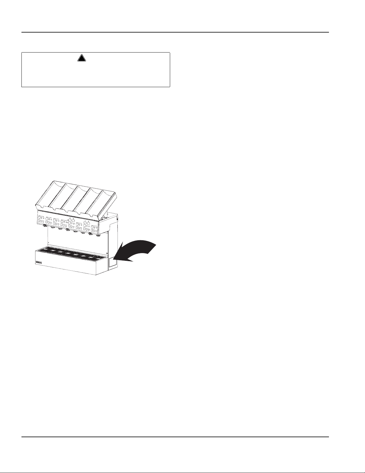
Serial Plate Location
Warranty Information
Consult your local MBE Distributor for terms and
conditions of your warranty. Your warranty specifically
excludes all beverage valve brixing, general
adjustments, cleaning, accessories and related
servicing.
Your warranty card must be returned to MBE to activate
the warranty on this equipment. If a warranty card is not
returned, the warranty period can begin when the
equipment leaves the MBE factory.
No equipment may be returned to MBE without a written
Return Materials Authorization (RMA). Equipment
returned without an RMA will be refused at MBE’s dock
and returned to the sender at the sender’s expense.
Please contact your local MBE distributor for return
procedures.
1-2
Part Number 020002777 10/11
Page 11
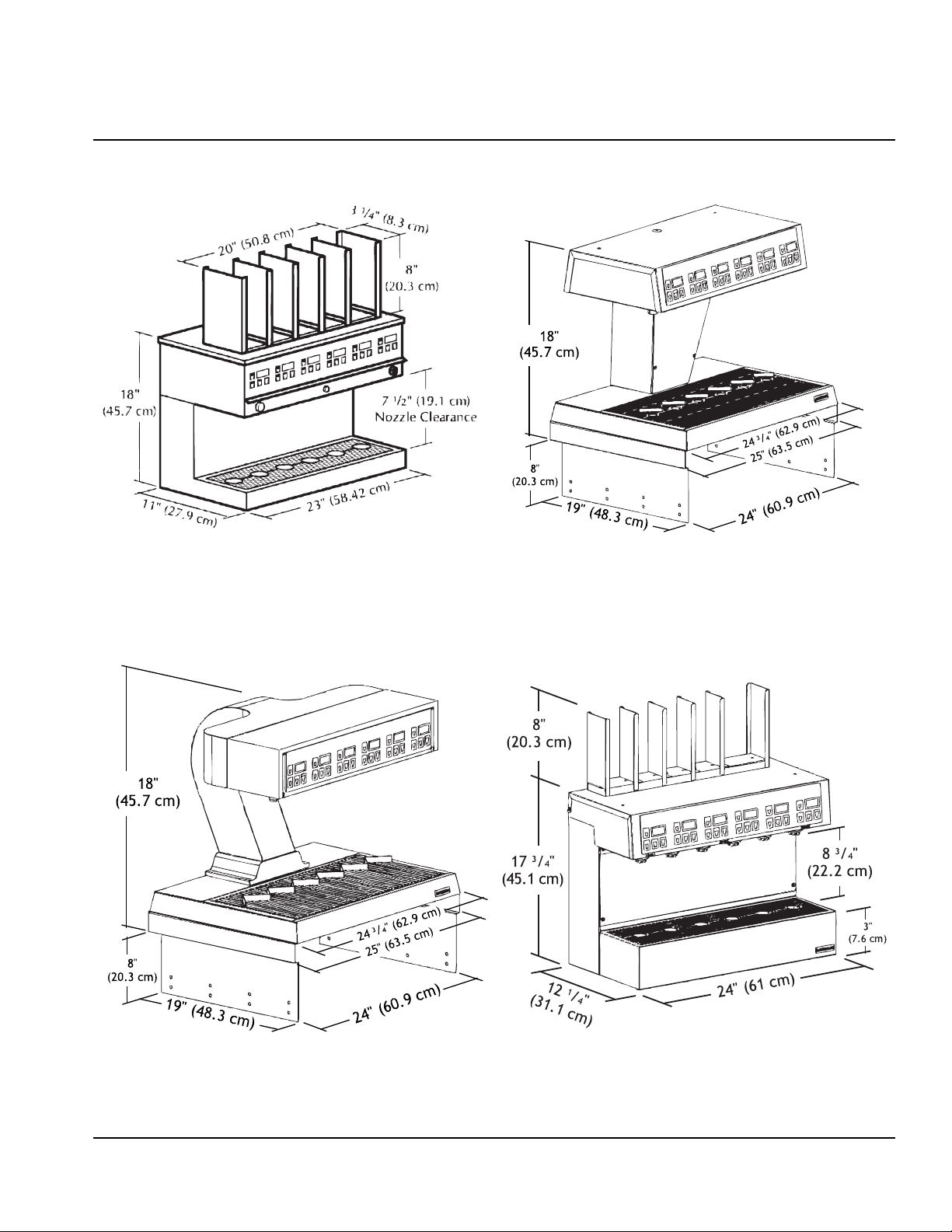
Section 2
MODEL 116
MODEL 126 (V-STYLE)
MODEL 136
MODEL 126 (S-STYLE)
Installation
DIMENSIONS AND CLEARANCES — ALL MODELS
Part Number 020002777 10/11 2-1
Page 12
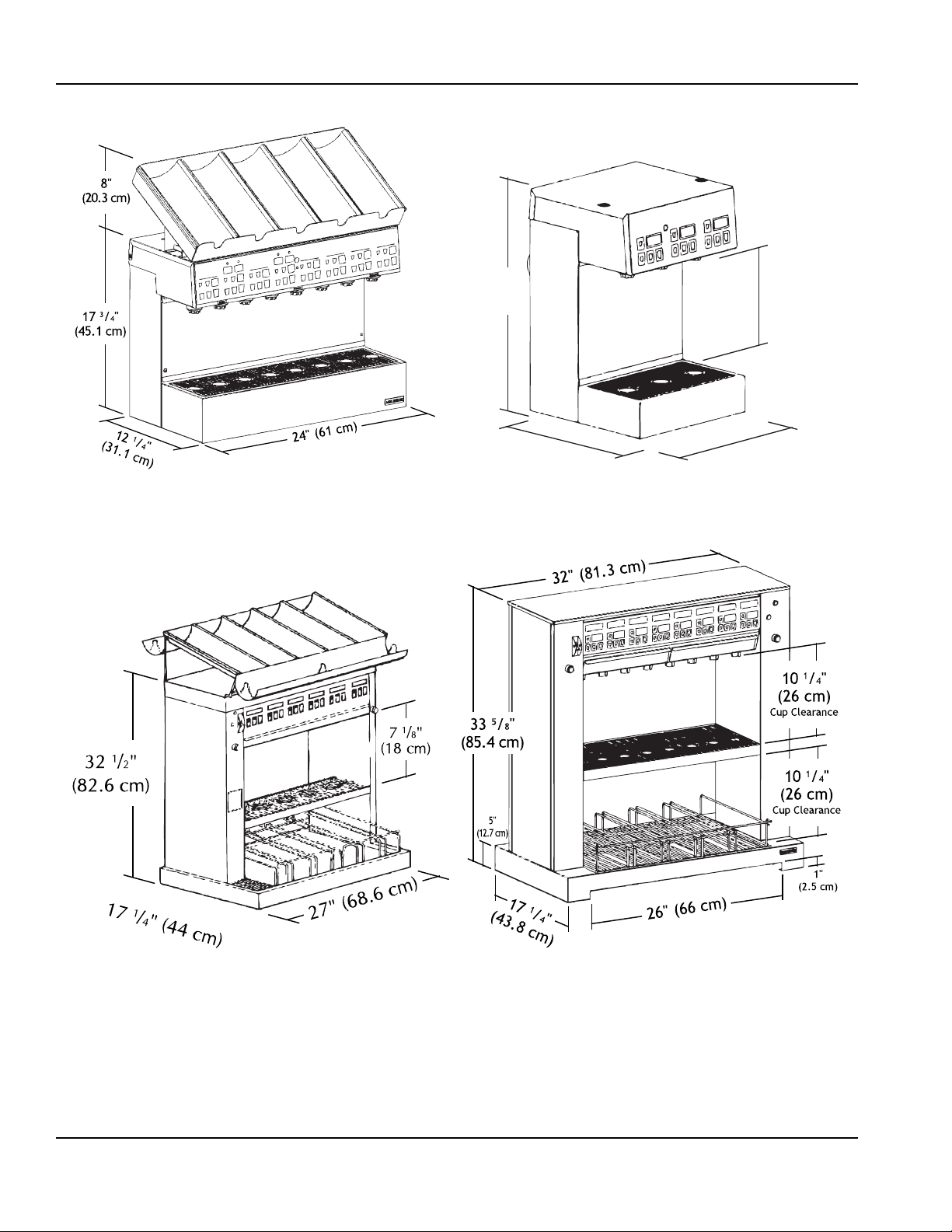
Installation Section 2
MODEL 138
MODEL 143
MODEL 158
MODEL 156
8" (20.3 cm)
cup clearance for
18 3/8"
(46.7 cm)
12
3
/
8
" (31.4 cm)
12" (30.5 cm)
3" tall drain pan
9 1/2" (24.1 cm)
cup clearance for
1
1
/2" tall drain pan
P.N. 00914300
2-2
Part Number 020002777 10/11
Page 13
Section 2 Installation
MODEL 158 (HIGH CUP CLEARANCE)
MODEL 1310 (WITH DRAIN PAN)
MODEL 1310 (NO DRAIN PAN)
Part Number 020002777 10/11 2-3
Page 14
Installation Section 2
MODEL 116
MODEL 126 (V & S-STYLE TOWERS)
FOOTPRINTS - ALL MODELS
2-4
Part Number 020002777 10/11
Page 15

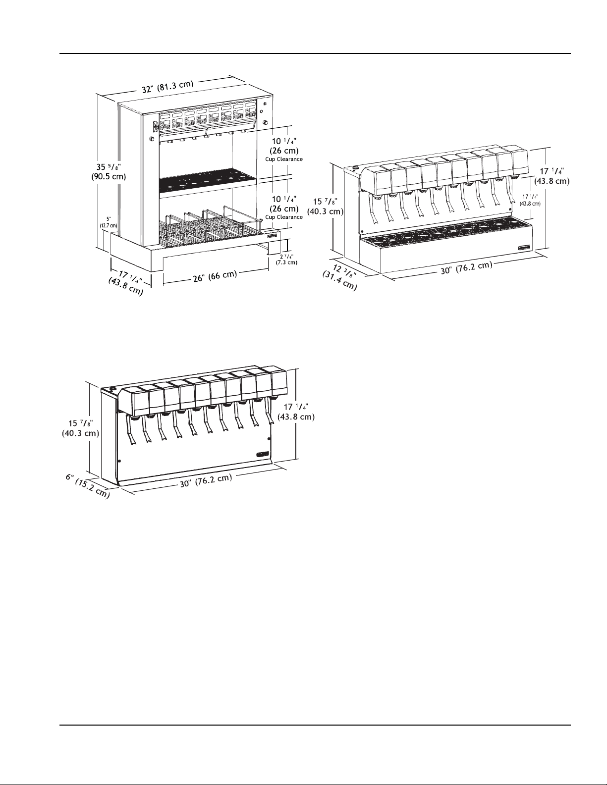
Section 2 Installation
MODEL 136
MODEL 138
Part Number 020002777 10/11 2-5
Page 16

Installation Section 2
MODEL 143
2-6
Part Number 020002777 10/11
Page 17

Section 2 Installation
MODEL 156 (LEFT HAND PASS-THRU)
MODEL 156 (RIGHT HAND PASS-THRU)
Part Number 020002777 10/11 2-7
Page 18

Installation Section 2
MODEL 158
2-8
Part Number 020002777 10/11
Page 19

Section 2 Installation
MODEL 1310
Part Number 020002777 10/11 2-9
Page 20

Installation Section 2
!
Warning
!
Warning
Safe Installation Dos and Don’ts
Read the following warnings before beginning an
installation. Failure to do so may result in possible
death or serious injury.
• DO adhere to all National and Local Plumbing and
Electrical Safety Codes.
• DO turn OFF incoming electrical service switches
when servicing, installing, or repairing equipment.
• DO check that all flare fittings are tight. This check
must be performed with a wrench to ensur e a quality
seal.
• DO inspect pressure on regulators before starting up
equipment.
• DO protect eyes when working around refrigerants.
• DO use caution when handling metal surface edges
of all equipment.
• DO handle CO
Secure cylinders properly against abrasion.
• DO store CO
• DO NOT exhaust CO
into an enclosed area, including all types of walk-in
coolers, cellars, and closets.
• DO NOT throw or drop a CO
cylinder(s) in an upright position with a chain.
• DO NOT connect the CO
product container. Doing so will result in an explosion
causing possible death or injury. It is best to connect
the CO
cylinder(s) to a regulator(s).
2
• DO NOT store CO
125°F (51.7°C) near furnaces, radiator or sources of
heat.
• DO NOT release CO
• DO NOT touch refrigeration lines inside units; some
may exceed temperatures of 200°F (9 3. 3° C) .
NOTICE: All utility connections and fixtures must be
sized, installed, and maintained in accordance with
Federal, State, and Local codes.
cylinders and gauges with care.
2
cylinder(s) in well ventilated areas.
2
gas (example: syrup pump)
2
cylinder. Secure the
2
cylinder(s) directly to the
2
cylinders in temperature above
2
gas from old cylinder.
2
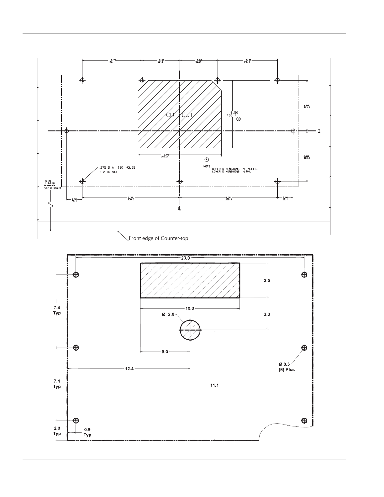
Location Requirements
LOCATION OF THE DISPENSING TOWER
1. Determine the location where the Multiplex
Dispensing Tower will be installed.
2. Locate the mounting template provided with the
tower installation kit.
3. Using the mounting template as a guide, punch out
the required holes in the counter top.
RATINGS
NOTE: Refer to nameplate on side of unit for voltage
and amperage specifications. Optional equipment may
require additional power supplies.
Carbon Dioxide (CO2) displaces oxygen. Exposure
to a high concentration of CO
which are followed rapidly by loss of consciousness
and suffocation. If a CO
particularly in a small area, immediately ventilate the
area before repairing the leak. CO
must not be installed in an enclosed space. An
enclosed space can be a cooler or small room or
closet. This may include convenience stores with
glass door self serve coolers. If you suspect CO
may build up in an area, venting o f the BIB pumps
and/or CO
monitors must be utilized.
2
KITCHEN EQUIPMENT INSTALLER REPRESENTATIVE RESPONSIBILITIES
Prior to scheduling Multiplex Equipment installer,
the following steps listed below must be completed:
1. Usable floor sewer drain.
2. Refer to electrical requirement chart for your model.
3. Usable potable water.
4. CO
Gas (bulk or bottled supply); minimum 3/8" line.
2
5. One 5 gallon (19 L) container or Bag-In-Box
container of each post mix syrup flavor.
6. A 120 VAC, 3-wire, 1 Phase, 60 Hz dual wall
receptacle for optional electrical equipment
(domestic only).
NOTE: Do not schedule the authorized Multiplex
Equipment Installer until all of the above have been
completed. It will only result in charge-backs to you for
the unnecessary trips.
gas causes tremors,
2
gas leak is suspected,
2
lines and pumps
2
2
2-10
Part Number 020002777 10/11
Page 21

Section 2 Installation
Important
Important
!
Warning
REQUIREMENTS
• Conduit can be run through floor or ceiling chase.
• 60°F (15.6°C) minimum and 105°F (40.5°C)
maximum operating ambient conditions.
• For indoor installation only.
• Syrup supply can be located on stand or adjacent to
refrigeration unit.
Installer Instructions
The remainder of these instructions is to be
completed by an authorized Multiplex Installer.
These equipment instructions are intended to assist
qualified personnel in the unpacking, locating and the
initial operation of the Multiplex Beverage Equipment
and/or Post Mix Refrigeration Unit.
This publication must be saved for future reference.
Read instructions before attempting installation.
Electrical
GENERAL
All wiring must conform to local, state and national
codes.
MINIMUM CIRCUIT AMPACITY
The minimum circuit ampacity is used to help select the
wire size of the electrical supply. (Minimum circuit
ampacity is not the beverage/ice machine’ s running amp
load.) The wire size (or gauge) is also dependent upon
location, materials used, length of run, etc., so it must be
determined by a qualified electrician.
ELECTRICAL REQUIREMENTS
Refer to Machine Model/Serial Plate for
voltage/amperage specifications.
ELECTRICAL SPECIFICATIONS
ALL TOWERS
PREPARATION
The Multiplex Beverage Equipment Soda Tower is preassembled in the factory and requires min im um
installation.
For future reference or to be used when ordering parts,
record the Model Number, Serial Number, Part Numbers
of Unit, Condenser (if remote), Towers, etc., and Date of
Installation on the inside of this Manual. Leave manual
on site in a safe place. Do not discard manual.
Ambient Location Requirement
This equipment is rated for indoor use only. It will not
operate in sub-freezing temperature. In a situation when
temperatures drop below freezing, the equipment must
be turned off immediately and properly winterized.
Contact the manufacturer for winterization process.
120 or 220VAC primary
24 VAC secondary
50/60Hz
MAKING THE ELECTRICAL CONNECTIONS
1. Locate the low voltage transformer and position it
below the tower in a shielded and protected area. Use
the screws provided to secure the transformer to the
cabinet.
2. Route the transformer cords up to the rear of the
dispensing tower and plug into the cords in the rear of
the tower.
3. Connect the transformer power supply cord to an
appropriate wall outlet. Do Not turn "on" the power
switch at this time.
Part Number 020002777 10/11 2-11
Page 22

Installation Section 2
!
Warning
!
Warning
!
Warning
GROUNDING INSTRUCTIONS
When using electric appliances, basic precautions
The beverage/ice machine must be grounded in
accordance with national and local electrical codes.
This appliance must be grounded. In the event of
malfunction or breakdown, grounding provides a path of
least resistance for electric current to reduce the risk of
electric shock. This appliance is equipped with a cord
having an equipment-grounding conductor and a
grounding plug. The plug must be plugged into an
appropriate outlet that is properly inst alled and grounded
in accordance with all local codes and ordinances.
Improper connection of the equipment-grounding
conductor can result in a risk of electric shock. The
conductor with insulation having an outer surface
that is green with or without yellow stripes is the
equipment grounding conductor. If repair or
replacement of the cord or plug is necessary, do not
connect the equipment-grounding conductor to a
live terminal. Check with a qualified electrician or
serviceman if the grounding instructions are not
completely understood, or if in doubt as to whether
the appliance is properly grounded. Do not modify
the plug provided with the appliance — if it will not fit
the outlet, have a proper outlet installed by a
qualified electrician.
must always be followed, including the following:
a. Read all the instructions before using the
appliance.
b. To reduce the risk of injury, close supervision is
necessary when an appliance is used near
children.
c. Do not contact moving parts.
d. Only use attachments recommended or sold by
the manufacturer.
e. Do not use outdoors.
f. For a cord-connected appliance, the following
shall be included:
• Do not unplug by pulling on cord. To unplug,
grasp the plug, not the cord.
• Unplug from outlet when not in use and
before servicing or cleaning.
• Do not operate any appliance with a
damaged cord or plug, or after the appliance
malfunctions or is dropped or damaged in any
manner. Contact the nearest authorized
service facility for examination, repair, or
electrical or mechanical adjustment.
g. For a permanently connected appliance — Turn
the power switch to the off position when the
appliance is not in use and before servicing or
cleaning.
h. For an appliance with a replaceable lamp —
Always unplug before replacing the lamp.
Replace the bulb with the same type.
2-12
i. For a grounded appliance — Connect to a
properly grounded outlet only. See Grounding
Instructions.
Part Number 020002777 10/11
Page 23

Section 2 Installation
FIGURE 1
Mounting The Dispensing Tower
SECURED BY BOLTING TO THE COUNTER
1. Locate the drain pan and mounting screws. Mount the
dispensing tower onto the counter.
2. Locate the rubber drain hose and clamp. Attach it to the
drain pan fitting.
3. Apply a bead of plumber's putty to the bottom of the tower.
4. Position the tower on the counter. Route the drain line,
electrical cord and product tubes through the opening in
the counter. Pull the tower backwards into position. V erify
that the drain pan is secure.
5. Remove the access panel. Locate the 1/4" 20 mounting
screws, flat washers, lock washers and nuts supplied in the
installation kit. Mount the tower via the slots inside the
tower.
SECURED WITH MOUNTING CLAMPS
View "A"
Dispensing Tower
Counter Top
Internal
Tooth
Washer
View "B"
Flat Counter
Dispensing
Tower
Counter Top
Internal
Tooth
Washer
1
/4"-20 Hex
Head
Screw
Angle
Bracket
1
/4"-20
Hex Head
Screw
Angle
Bracket
Pre-formed Counter-Top
1. Position the tower on the counter-top in it's final location.
2. Locate the rubber drain hose and clamp. Attach it to the
drain pan fitting.
3. Locate the angle mounting clamps, the 1/4"-20 x 1" Hex
Head screws, and the internal tooth washers supplied with
tower installation kit.
4. Secure the tower to the counter top with angle mounting
clamps, screws, and washers provided in kit. (see figure 1)
NOTE: If the tower is to be mounted to a flat counter top
as in Figure 1 View B, it will be necessary to seal the
edge of the tower to the counter top with R.T.V. sealant.
5. Route the beverage conduit up to the stainless steel Barb
Stem Adaptors at the base of the dispensing tower . If the
lines of the conduit are of different lengths, always connect
the shortest line first. Use two (2) tab clamps at every
connection.
Part Number 020002777 10/11 2-13
Page 24

Installation Section 2
Plumbing – General
CONNECTING THE SYRUP AND WATER LINES
Model 138CDA or 138CDAX
1. Locate the Barb-stem splicers and tab-clamps in the
installation kit.
NOTE: The Installation Kit provides syrup connections
for 1/2 or 3/8 ID conduits. The circulating carbonated
Water Lines are supplied with 1 /2 Barbs only. Determine
the conduit size prior to the attaching Barb systems.
2. Attach the 1/4" Barb of the 1/4" x 1/2" or 1/4" x 3/8"
Barb splicer to the Syrup Lines in the tower labeled
#1, #2, #4, #5, #6, #7, and #8. clamp in place with
tab clamp.
3. Attach the four (4) 1/2" x 1/2" Barb splicers to the
tower lines labeled "AF or AR" and "BF or BR".
Clamp in place with tab clamp (refer to "Note"
below).
4. Route the beverage conduit up to the tower. If the
lines of the conduit are different lengths, always
connect the shortest line first. Use two (2) tab
clamps per connection.
5. Using the plumbing diagram (located in this manual)
as a guide for steps 5 through 7 attach the tower
Syrup Lines labeled #1, #2, #3, #4, #5, #6, #7 and
#8 to the corresponding numbered or colored line of
the conduit. Clamp in place.
Model 136EDA, 136EDAX, 138EDA, or 138EDAX
1. Locate the Barb stem splicers and tab clamps in the
installation kit.
NOTE: The Installation Kit provides syrup connections for
1/2 or 3/8 ID conduits. The circulating carbonated W ater
lines are supplied with 1/2 Barbs only . Determine the conduit
size prior to the attaching Barb systems.
2. Attach the 1/4" Barb of the 1/4" x 1/2" or 1/4" x 3/8" Barb
splicer to the Syrup Lines in the tower labeled #1, #2,
#3, #4, #5, and #6. Clamp in place with tab clamp.
3. Attach the two (2) 1/2" x 1/2" Barb splicers to the tower
lines labeled "AF or AR". Clamp in place with tab clamp.
4. Route the beverage conduit up to the tower. If the lines
of the conduit are different lengths, always connect the
shortest line first. Use (2) tab clamp s per connection .
5. Using the Plumbing diagram (in this manual) as a guide
for steps 5 through 7, attach the tower Syrup Lines
labeled #1, #2, #3, #4, #5, and #6 to the corresponding
numbered or colored line of the conduit. Clamp in place.
6. Connect the plain water supply to the line labeled "WF
or WR". Clamp with tab clamp.
7. Attach the Carbonated Water Line to the line labeled
"AF or AR". Clamp in place
6. Connect the plain water supply to the line labeled
"WF or WR". clamp with tab clamp.
7. Attach the Carbonated Water Line to the line labeled
"AF or AR" and "BF or BR". Clamp in place.
NOTE: If a Single Circuit is used, run "AF or AR" In and
"AF or AR" Out to "BF or BR" In. Route "BF or BR" back
to conduit.
2-14
Part Number 020002777 10/11
Page 25

Section 2 Installation
Model 136FDA, 136FDAX, 138FDA, or 138FDAX
1. Locate the Barb stem splicers and tab clamps in the
installation kit.
NOTE: The Installation Kit provides syrup connections
for 1/2 or 3/8 ID conduits. The circulating carbonat ed
Water lines are supplied with 1/2 Barbs only. Determine
the conduit size prior to the attaching Barb systems.
2. Attach the 1/4" Barb of the 1/4" x 1/2" or 1/4" x 3/8"
Barb splicer to the Syrup Lines in the tower labeled
#1, #2, #3, #4, #5, and #6. Clamp in place with tab
clamp.
3. Attach the two (2) 1/2" x 1/2" Barb splicers to the
tower lines labeled "AF or AR". Clamp in place with
tab clamp.
4. Route the beverage conduit up to the tower. If the
lines of the conduit are different lengths, always
connect the shortest line first. Use (2) tab clamps
per connection.
5. Using the Plumbing diagram (in this manual) as a
guide for steps 5 through 7, attach the tower Syrup
Lines labeled #1, #2, #3, #4, #5, and #6 to the
corresponding numbered or colored line of the
conduit. Clamp in place.
6. Connect the plain water supply to the line labeled
"WF or WR". Clamp in place.
7. Attach the Carbonated Water Line to the line labeled
"AF or AR". Clamp in place Water Supply
Model 136LDA, 136LDAX, 138LDA, or 138LDAX
1. Locate the Barb-stem splicers and tab-clamp s in the
installation kit.
NOTE: The Installation Kit provides syrup connections
for 1/2 or 3/8 ID conduits. The circulating carbonate d
Water Lines are supplied with 1/2 Barbs only. Determine
the conduit size prior to the attaching Barb systems.
2. Attach the 1/4" Barb of the 1/4" x 1/2" or 1/4" x 3/8"
Barb splicer to the Syrup Lines in the tower labeled
#1, #2, #4, #5, #6, #7, and #8. clamp in place with
tab clamp.
3. Attach the four (4) 1/2" x 1/2" Barb splicers to the
tower lines labeled "AF or AR" and "BF or BR".
Clamp in place with tab clamp (refer to "Note"
below).
4. Route the beverage conduit up to the tower. If the
lines of the conduit are different lengths, always
connect the shortest line first. Use two (2) tab
clamps per connection.
5. Using the plumbing diagram (located in this manual)
as a guide for steps 5 through 7 attach the tower
Syrup Lines labeled #1, #2, #3, #4, #5, #6, #7 and
#8 to the corresponding numbered or colore d line of
the conduit. Clamp in place.
6. Connect the plain water supply to the line labeled
"WF or WR". clamp with tab clamp.
7. Attach the Carbonated Water Line to the line labeled
"AF or AR" and "BF or BR". Clamp in place.
NOTE: If a Single Circuit is used, run "AF or AR" In and
"AF or AR" Out to "BF or BR" In. Route "BF or BR" back
to conduit.
Part Number 020002777 10/11 2-15
Page 26

Installation Section 2
Model 138EDA2
1. Locate the Barb-stem splicers and tab-clamps in the
installation kit.
NOTE: The Installation Kit provides syrup connections
for 1/2 or 3/8 ID conduits. The circulating carbonated
Water Lines are supplied with 1 /2 Barbs only. Determine
the conduit size prior to the attaching Barb systems.
2. Attach the 1/4" Barb of the 1/4" x 1/2" or 1/4" x 3/8"
Barb splicer to the Syrup Lines in the tower labeled
#1, #2, #4, #5, #6, #7, and #8. clamp in place with
tab clamp.
3. Attach the four (4) 1/2" x 1/2" Barb splicers to the
tower lines labeled "AF or AR" and "BF or BR".
Clamp in place with tab clamp (refer to "Note"
below).
4. Route the beverage conduit up to the tower. If the
lines of the conduit are different lengths, always
connect the shortest line first. Use two (2) tab
clamps per connection.
5. Using the plumbing diagram (located in this manual)
as a guide for steps 5 through 7 attach the tower
Syrup Lines labeled #1, #2, #3, #4, #5, #6, #7 and
#8 to the corresponding numbered or colored line of
the conduit. Clamp in place.
Model 115, & 116
1. Locate the Barb-stem splicers and tab-clamps in th e
installation kit.
NOTE: The Installation Kit provides syrup connections
for 1/2 or 3/8 ID conduits. The circulating carbonate d
Water Lines are supplied with 1/2 Barbs only. Determine
the conduit size prior to the attaching Barb systems.
2. Attach Barb splicer to the syrup lines labeled #1, #2,
#3, #4, and #5 ("6" and "W" if it is a six (6) valve
tower). Clamp in place with ta clamps. Attach the
two (2) 1/2 x 1/2 Barb splicers to the lines labeled #7
Carbonated Water and #8 Carbonated Water then
clamp in place.
3. Attach the syrup lines labeled #1, #2, #3, #4, #5, and
#6 (for six (6) valve towers application only) to the
corresponding numbered or colored lines of the
conduit. Clamp in place using two (2) clamps each.
4. Connect the plain water line (labeled "W") to the
plain water supply and clamp in place (for six (6)
valve tower application only).
5. Attach the Carbonated Water line to the line labeled
#7 Carbonated Water and #8 Carbonated Water,
then clamp in place.
6. Connect the plain water supply to the line labeled
"WF or WR". clamp with tab clamp.
7. Attach the Carbonated Water Line to the line labeled
"AF or AR" and "BF or BR". Clamp in place.
NOTE: If a Single Circuit is used, run "AF or AR" In and
"AF or AR" Out to "BF or BR" In. Route "BF or BR" back
to conduit.
2-16
Part Number 020002777 10/11
Page 27

Section 2 Installation
Model 156, 158, & 1510
1. Route the Beverage Cond uit up to the stainless
steel Barb St em Adaptors at the base of the tower. If
the lines of the conduit are of different lengths,
always connect the shortest line first. Use two (2)
tab clamps at every connection.
NOTE: The Model 158 and 1510 Pass-Thru towers have
two (2) internal Carbonated Water Circuits. Use the
Carbonated Water lines #8, and #9 to connect to the
lines labeled "xF or xR" and "A". Connect the
Carbonated Water Lines labeled #7 an d #10 to th e line s
labeled "xF or xR" and "B". If the refrigeration unit has
only one (1) Carbonated Water Circuit, these lines must
be connected together.
2. Attach the syrup lines labeled "1" through "6", "1"
through "8", or "1" through "10" to the corresponding
numbered Barb fittings of the tower. Use two (2) tab
clamps per connection.
3. Attach the Non-carbonated Water Line (labeled "W")
of the beverage conduit to the Barb Stem of the
tower labeled "W". Use two (2) tab clamps.
Model 126LDP
1. Route the beverage conduit up to the base of the
tower. If the lines of the conduit are different lengths,
always connect the shortest line first. Use two (2)
Tab Clamps at every connection.
NOTE: The Multiplex Model 126 Front Draw Dispensing
Tower has only one internal carbonated water circuit.
2. Attach the six (6) Syrup Lines labeled 1, 2, 3, 4, 5,
and 6 to the corresponding numbered Barb Fittings
of the tower . Use two (2) t ab clamp s per co nnection.
If conduit has non-numbered colored tubing, use the
"Conduit Number to Color Reference Chart" listed in
these instructions.
3. Attach the Plain Water line (labeled "W") of the
beverage conduit to the Barb System of the tower
labeled "W". Use two (2) tab clamps. If six (6)
Carbonated Water Valves are required, use 1/4" tee
provided to connect the carbonated line to "W" line.
Part Number 020002777 10/11 2-17
Page 28

Installation Section 2
Model 1310
1. Locate the Barb stem splicers and tab clamps in the
install kit.
NOTE: The Installation Kit provides syrup connections
for the 1/2 or 3/8 ID conduit. The circulating carbonated
water lines are supplied with 1/2 barbs only. Determine
the conduit size prior to the attaching barb systems.
2. Attach barb splicer to the syrup lines labeled #1, #2,
#3, #4, #5, #6, #7, #8, #9 and #10 and clamp in
place. Attach two (2) 1/2 x 1/2 barb splicers to the
lines labeled #7 Carbonated Water and #8
Carbonated Water and clamp in place. Attach one
(1) 1/2 x 1/2 barb splicer to the line labeled "W" and
clamp in place.
3. Attach the syrup lines labeled #1, #2, #3, #4, #5, #6,
#7, #8, #9 and #10 to the corresponding number or
color lines of the conduit. Clamp in place.
4. Connect the plain water line labeled "W" to the plain
water supply and clamp in place.
5. Attach the Carbonated water line to the line labeled
#7 Carbonated Water and #8 Carbonated Water,
then clamp in place.
Model 143
1. Route the beverage conduit up to the stainless steel
barb stem adaptors at the base of the dispensing
tower. If the line s of the conduit are dif ferent lengths,
always connect the shortest line first. Use two (2)
tab clamps at every connection.
2. Attach the three (3) syrup lines labeled #1, #2, and
#3 to the corresponding numbered barb fittings of
the dispensing tower. Use two (2) tab clamps per
connection.
3. Attach the Carbonated Water line labeled "xF or xR"
of the beverage conduit to the barb stem of the
tower labeled "xF or xR". Use two (2) tab clamps.
How to Insulate all the Connections
NOTE: Make sure all exposed Carbonated Water, Plain
Water, and Syrup Lines are well insulated.
1. To insulate use conduit sections, aluminum foil and
tape.
2. Cut the conduit sections to fit snugly over the
exposed lines and fittings.
3. After all the lines are properly insulated, wrap tightly
with tape to assure air tightness. This will prevent
condensation from forming on the lines and prevent
dripping.
2-18
Part Number 020002777 10/11
Page 29

Section 3
Important
Portion Control Keyboard Layout
Six (6) Valve Tower Keyboard
Eight (8) Valve Tower Keyboard
FIGURE 2
Operation
Calibration of the Dispensing Valves
SET THE FLOW (WATER FLOW RATE ONLY)
For Electronic Volumetric Valves use OEM valve
manual (skip this section).
Check that the Primary CO
or Bulk CO
Pressure Regulator for sugar-based syrup must be
adjusted to 60 psi (4 bar). The Low Pressure Regulator for
sugar-free syrup must be adjusted to 14-16 psi (0.9-
1.1 bar).
1. Turn “off” the syrup at the dispensing valve by
2. Check the Water Shut-off (if applicable). It should be
NOTE: The Syrup and Water Shut-off (if equipped) are
not to be used as an alternate for flow controls. They are
to be used only for shutting “on” or “off” the syrup and/or
the water supply.
2 Regulator is adjusted properly. The Medium
turning the Syrup Shut-off (located on the valve
mounting block). If there is no syrup shut-off, use a
Syrup Separator.
in the full “open” position.
2 Tank High Pressure Regulator
3. Place a Volume Cup with 10 oz (295.7 ml)
measurement line, under valve to be adjusted. If
using Syrup Separator, place Volume Cup under
water side of separator only.
4. To adjust the water flow rate (if necessary), turn the
adjusting screw clockwise to increase. Turn the
adjusting screw counterclockwise to decrease the
flow of water.
A. Press CAL pad three (3) times in less than 3
seconds to enter Calibrate Mode. Calibrate lamp
will light. (Omit this step if already in Calibration
Mode).
B. Press STOP-FILL pad of valve to adjusted once
to cause 4 second pour into V olume Cup.
5. Repeat 4 second dispense (STOP-FILL pad) and
water flow adjustment until volume is correct.
6. Open Syrup Shut-off or remove Syrup Separator (if
applicable).
7. Repeat this procedure (steps 1 through 6 above) for
each valve.
8. Press CAL button once to exit Calibrate Mode.
Calibrate lamp will go “off”.
Part Number 020002777 10/11 3-1
Page 30

Operation Section 3
SET THE RATIO (WATER T O SYRUP MIXTURE)
1. Remove valve nozzle by turning the nozzle and pulling
down.
2. Place Syrup Separator on valve to be adjusted. Actuate
the valve manually (pad, lever) until both syrup and water
flow out of the syrup/water separator .
3. Position the proper ratio cup under the Syrup Separator .
Manually Actuate the valve pad or lever valve (pad,
lever). Dispense until at least 3/4 of the ratio cup is filled.
Both products should fill to the same level.
4. T o adjust the syrup flow (if levels are not equal), turn the
syrup flow control adjusting screw clockwise to increase.
Turn the syrup flow control adjusting screw
counterclockwise to decrease the flow of syrup.
NOTE: Do not adjust the water flow during this procedure.
5. After syrup is adjusted, remove the Syrup Separator and
replace the valve nozzle.
6. Repeat this procedure (steps 1 through 5 above) for the
remaining valves.
For Special Dual Flavor Dispensing V alves
NOTE: The Syrup Separator is not used on second flavor.
1. Make sure first flavor (keypad and LED to left) is selected
when testing Ratio as above.
2. Make sure second flavor (keypad and LED to right) is
selected when testing Ratio as follows. Leave original
nozzle on.
3. Rotate proper Ratio Cup 90o so it catches the second
flavor syrup from tube just back of nozzle on bottom of
valve.
4. Dispense until at least 3/4 of the ratio cup is filled. Both
products should fill to the same level.
5. Adjust Syrup flow as necessary as stated above (step 4
under "Hot to set the Ratio (water to syrup mixture)".
SET THE VOLUME (DRINK PORTION SIZES)
1. T o enter the Portion Control Calibrate Mode, press CAL
pad three (3) times in less than 3 seconds. The calibrate
lamp will illuminate.
2. Use Volume Cup with finished drink marking lines, or use
correct size sample cup with desired volume of ice.
3. Press and hold respective SIZE pad until product gets
close to proper finished drink mark, or until close to top of
sample cup.
4. Release SIZE pad before reaching final mark or before
foam exceeds final mark. Press SIZE pad again
momentarily , as many times as is necessary (letting foam
settle), to get to the correct finished drink mark.
5. Repeat steps 2 through 4 above for all sizes and all
stations (products) needing calibration. Be sure to use the
correct Volume Cup finished drink marking line, or correct
sample cup size and ice amount, for each size pad.
NOTE: If you fill above the final mark or need to "start over" for
any reason, you must exit the Calibrate Mode and then reenter the Calibrate Mode to resume.
6. Exit Calibrate Mode by pressing CAL pad once. Calibrate
light will go out. All changes will be permanently saved.
RUN MODE
Size Buttons
Press any size button (0, 1, 2, 3, or 4) on any station to
dispense product for that station for pre-programmed time for
that respective size.
STOP-FILL Buttons
If no dispense is in progress, press any STOP-FILL button to
manually dispense from the station. If portion dispense is in
progress, press the STOP-FILL button to manually cancel.
Portion Control Water/Soda dispensing
Press either the WATER or the SODA b utton momentarily.
Now press any size button on the respective station (within
2 seconds maximum). Portion dispense will continue
automatically for that size only .
Optional Dual Flavor Keyboard
NOTE: Station No. 2 and No. 4 have Dual Flavors.
1. Press the flavor button and its associated LED will come
“on”.
2. Press any size button to dispense this flavor and size. If the
required flavor button LED is already “on”, press the size
button desired.
NOTE: The left LED flavor is the default on both stations.
3-2
Part Number 020002777 10/11
Page 31

Section 3 Operation
Program modes
PROGRAM MODE CAL NO. 1 (TOTAL VOLUME)
To enter the Calibrate No. 1 mode, simultaneously press
the CAL button and the Size 1 button (1) on any station.
You may also press the CAL button three times within
three seconds. The CAL light will come “on” constantly.
Volume Sizing
NOTE: Use a Calibration Cup (or an appropriate size
cup with the proper amount of ice).
1. Press the respective size button for that cup (0, 1, 2,
3, or 4) at that station.
2. Fill the cup with product to the correct level.
NOTE: This same size button may be started and
stopped as many times as desired to acquire the correct
level while letting the drink settle. All times for the same
station and size are additive in the program session.
3. Repeat volume sizing procedure for all sizes and
stations needing programming.
Flow Rate Calibration
In the Calibrate No. 1 Mode, press any STOP-FILL
button one (1) time. That respective valve will flow for
exactly 4 seconds allowing for checking or adjusting the
valve flow rate.
One Station Sets All
Immediately after entering the Calibrate No. 1 Mode,
press any STOP-FILL button two (2) times in less than
1 second. The CAL light will flash constantly, 2 ti mes per
second. Now all volumes on that station programmed in
this session, will copy to all other stations when exiting.
Exiting the Program Mode, CAL No. 1
To exit, press the CAL button one (1) time turning “off”
the CAL light. All volume changes made during this
session will be permanently stored.
PROGRAM MODE CAL NO. 2 (INCREMENTAL)
To enter Calibrate No. 2 Mode, simult aneously press the
CAL button and the Size 2 button (2) on any station. The
CAL light will flash constantly, one (1) time per second.
Volume incrementing/decrementing
1. Press the size button (0, 1, 2, 3, or 4) on the specific
station that needs a small increment of time
adjustment. The CAL light will come “on” constantly
indicating this size/station time is selected.
2. To increase time, press the Size 4 button () at this
time. Each press of the Size 4 button () will increase
total selected size stored time by 0.1 seconds. The
CAL light will go “off” every time button is pressed.
Example: 10 presses = 1 second.
3. To decrease time, press the Size 1 button () at this
time. Each press of the Size 1 button () will decrease
total selected size stored time by 0.1 seconds. The
CAL light will go “off” every time button is pressed.
4. Press STOP-FILL button on this station to
temporarily save new time for this size this station.
The CAL light will resume flashing.
5. Repeat procedure 1 through 5 for any other size or
station needing incremental time programming
Exiting the Program Mode, CAL No. 2
To exit, press the CAL button one (1) time turning “off”
the flashing CAL light. All incremental volume changes
made during this session will be permanently stored.
PROGRAM MODE CAL NO. 3 (WATER/SODA)
NOTE: This is set at the factory to station number 2
(water) and 4 (soda). This may have to be reset in the
field if someone inadvertently changes location, or if the
location must change stations.
T o enter water/soda programming mode, simultaneously
press the CAL button and SIZE 3 button () on any station
(refer to figure above). The CAL light will come “on”
constantly.
1. Before changing the water/soda pour stations, you
must make sure the correct WATER and SODA
solenoids (from the stations to be programmed ) ar e
wired correctly to J9 and J10 respectively.
2. Pressing SIZE 1 button on any station, will set the
special WA TER solenoid driver J10 to come ON with
all dispenses of THIS station, as well as the W ATER
button dispensing water from this station.
An automatic 2 second pour of water solenoid from this
station will occur, to verify setting.
3. Pressing SIZE 4 button on any specific station, will
set the special SODA solenoid driver J9 to come ON
with all dispenses of this station, as well as the
SODA button dispensing soda water from this
station.
An automatic 2 second pour of water solenoid from this
station will occur, to verify setting.
Exiting the programming mode, CAL No. 3.
To exit, press the CAL button one (1) time turning “off”
the CAL light. All water/soda changes made during this
session will be permanently stored.
Part Number 020002777 10/11 3-3
Page 32

Operation Section 3
TOP-OFF PROGRAM MODE
Top-Off Program Mode
To enter the top-off program mode, simultaneously
press CAL button and the Size 4 button () on any station.
You may also press the CAL button five times within
three seconds. The CAL light will flash five (5) times and
then remain “on”.
Enabling / Disabling the individual station Top-off
Enabling the individual station top-off allows every size
dispensed on this station to pour all the volume
programmed in two (2) pours with a 3 second delay
between pours. Disabling the individual station top-off
allows every size dispensed on this station to pour all the
volume programmed in one pour.
1. Press the STOP-FILL button on the station desired
to change the top-off mode.
2. The CAL light will immediately flash five (5) times to
indicate the top-off mode has been toggled. If the
respective station was disabled for top-off, then it will
toggle to enable for top-off. If the respective station
was enabled for top-off, then it will toggle to disable
for top-off.
Exiting the Top-off Program Mode
To exit the Top-off Program Mode, press the CAL button
one (1) time turning “off” the CAL light. All station top-off
mode changes made during this session will be
permanently stored.
TEST AND SANITATION MODE
1. With the power “off”, press the CAL button and turn
power “on” simultaneously.
2. Release the CAL button. The portion control board
will sequence each station for 4 seconds starting
with the left most (station No. 1).
3. Check that each LED on the Portion Control board
comes “on” sequentially and all valve solenoids
come “on”.
NOTE: If the drain can support more than one (1) valve
pouring at a time, press the STOP-FILL button on the
station number for the number of valves flowing
simultaneously.
Example: At station number 3, press the STOP-FILL
button. Three (3) valves will flow simultaneously.
NOTE: If the LED light does not come “on” for any
station(s), the Portion Control board is bad. If the LED
light comes “on” but the valve does not come “on”, check
wiring and valve solenoids.
INSTRUCTIONS FOR DUAL FLAVOR STATIONS
NOTE: Station No. 2 and 4 have Dual Flavors
1. Press the flavor and it's associated LED will come
"on"
2. Press any size button to dispense this flavor and
size. If the required flavor button LED is already
"on", press the size button desired.
NOTE: The left LED flavor is the default on both stations.
ENTERING WATER/SODA PROGRAMMING MODE
To enter wate r/soda programming mode, press and hold
the CAL button SIZE 3 buttons. The CAL light will come
ON instantly.
Pressing SIZE 1 button on any station, will set the
special WATER solenoid driver J10 to come ON with all
dispenses of THIS station, as well as water button
dispensing from this station. An automatic 2 second pour
of water from this station will occur, to verify setting.
Pressing SIZE 4 button on any specific station, will set
the special SODA solenoid driver J9 to come on. An
automatic 2 second pour of water from this station will
occur to verify setting.
Y ou must also make sure the correct WATER and SODA
solenoids (from the stations you just programmed) are
wired correctly to J9 and J10 respectively.
Equipment Setup and Close Procedure
EQUIPMENT SETUP PROCEDURE
1. Ensure that all valve nozzles are attached to the valves.
2. Observe pressure of CO
(34 bar) or more, or bulk CO
Primary regulator set at 90 psi (6 bar) and the secondary
regulator set at 35 psi (2.4 bar).
3. Observe the control panel to verify that all pressure
gauges are set at correct operating pressures.
4. Check the syrup tanks to make sure a sufficient number
of tanks are connected in series to satisfy business
volume.
5. Clean syrup inlet and outlet quick disconnects at the
same time tanks are replaced. Rinse disconnects in clean
potable water .
EQUIPMENT CLOSE PROCEDURE
1. Clean the underside of the dispensing tower around the
nozzle area with a clean damp towel.
2. Pour at least 60 oz (1.8 liters) of warm water down the
drain openings.
high pressure tank of 500 psi
2
tank of 150 psi or more.
2
3-4
Part Number 020002777 10/11
Page 33

Section 4
Maintenance
Maintenance Schedule
This section provides a list of periodic maintenance
tasks and the scheduled frequency required to ensu re
the proper operation of your Multiplex dispensing
equipment. To ensure quality beverages, prevent
downtime, and reduce costs, these tasks must be
performed as indicated.
PERIODIC MAINTENANCE LISTED BY MAJOR COMPONENTS
Dispensing stations
Daily (365 times per year)
• Take temperature of finished drinks. Pour off the first
and take the temperature of the second drink. The
proper temperature of drinks must be 40°F (4°C) or
less.
• Remove nozzles and diffusers from each dispensing
valve. Clean with soap and warm water (not hot).
Rinse with carbonated water and reinstall.
• Flush all dispenser drains. Pour hot water down
drains at closing.
Beverage conduits
Every 4 months (3 times per year)
• Inspect beverage conduits for damage. Re-insulate
and seal any un-insulated areas.
• Inspect floor chases and seal any open chase ends.
Air compressor
Monthly (12 times per year)
• Drain condensate water from air compressor tank.
Every 4 months (3 times per year)
• Inspect air compressor filter and replace if clogged.
Air filter must be replaced every 6 months.
• Inspect air compressor to verify cut-in at 70 psi (4.8
bar) and cut-out at 90 psi (6.3 bar). Adjust pressure
switch if necessary.
• Inspect system for air leaks and repair as required.
Refrigeration unit
Every 4 months (3 times per year)
• • Clean the refrigeration unit air-cooled condenser
using a vacuum cleaner. If equipped with watercooled condenser, verify the water discharge
temperature is at 105°F (41°C). Adjust water
modulating valve if necessary.
• Inspect water bath to verify water level is at the top of
stand pipe. If below, add water and repair water
makeup device. If excessive amount of water is
flowing over stand pipe, locate leak within bath and
repair.
• Inspect ice bank within the water bath to verify proper
size ice bank and clarity. Look for uniform, 2" to 4"
thick ice bank.
• Drain, clean, and refill water bath.
• Inspect agitator motor and ensure proper operation.
• Inspect the circulating motor/pump assembly. Clean
strainer and oil motor.
• Inspect the carbonating motor/pump assembly.
Clean strainer and oil motor.
• Inspect entire system for leaks and repair as
required.
Water filters
Every 4 months (3 times per year)
• Verify that incom ing water pressure is not less than
40 psi (2.8 bar) or greater than 60 psi (4.1 bar). If
equipped with a water regulator , verify proper setting
of 55 psi (3.8 bar). Adjust if necessary.
• If pressure is low, inspect water filter cartridges to
ensure they are able to supply adequate water
pressure under normal system flow. Replace if
unable to provide minimum 20 psi (1.4 bar) under
load.
Syrup supply
Daily (365 times per year)
• Clean general area of syrup hookup with soap and
warm water. Rinse off all soap.
Every 4 months (3 times per year)
• Inspect syrup lines for proper flavor identification
labels. Replace labels if necessary .
• Disconnect syrup containers. Clean connector with
soap and warm water. Rinse with plain water and
reconnect to syrup containers.
CO
2 gas supply
Every 4 months (3 times per year)
• Inspect pressure setting at CO
regulator. Verify proper 90 psi (6.3 bar) pressure
setting. Adjust if necessary.
2 high pressure
Part Number 020002777 10/11 4-1
Page 34

Maintenance Section 4
• Inspect pressure setting at syrup pressure regulators.
Verify propter pressure setting. Adjust if necessary.
• Inspect system for CO
2 leaks, repair as required.
PERIODIC MAINTENANCE LISTED BY SCHEDULED FREQUENCY
Daily (365 times per year)
• T ake temperature of finishe d drinks. Pour off the fir st and
take the temperature of the second drink. The prope r
temperature of drinks must be 40°F (4°C) or less.
• Remove nozzles and diffusers from each dispensing
valve. Clean with soap and warm water (not hot).
Rinse with carbonated water and reinstall.
• Flush all dispenser drains. Pour hot water down
drains at closing.
• Clean general area of syrup hookup with soap and
warm water. Rinse off all soap.
Every 4 months (3 times per year)
• Using Brix cup and syrup separator , check for proper
carbonated water flows (standard flow: 5 oz. in 4
seconds, fast flow: 10 oz. in 4 seconds) and syrup to
water ratios at each dispensing station. Adjust as
required.
• Inspect beverage conduits for damage. Re-insulate
and seal any un-insulated areas.
• Inspect floor chases and seal any open chase ends.
• Inspect air compressor filter and replace if clogged.
Air filter must be replaced every 6 months.
• Inspect the circulating motor/pump assembly. Clean
strainer and oil motor.
• Inspect the carbonating motor/pump assembly.
Clean strainer and oil motor.
• Inspect entire system for leaks and repair as
required.
• Verify that incom ing water pressure is not less than
40 psi (2.8 bar) or greater than 60 psi (4.1 bar). If
equipped with a water regulator , verify proper setting
of 55 psi (3.8 bar). Adjust if necessary. If pressure is
low, inspect water filter cartridges to ensure they are
able to supply adequate water pressure under
normal system flow. Replace if unable to provide
minimum 20 psi (1.4 bar) under load.
• Inspect syrup lines for proper flavor identification
labels. Replace labels if necessary.
• Disconnect syrup containers. Clean connector with
soap and warm water. Rinse with plain water and
reconnect to syrup containers.
• Inspect pressure setting at CO
2 high pressure
regulator. Verify proper 90 psi (6.3 bar) pressure
setting. Adjust if necessary.
• Inspect pressure setting at syrup pressure
regulators. Ver ify propter pressure setting. Adjust if
necessary.
• Inspect system for CO
2 leaks. Repair as required.
• Inspect air compressor to verify cut-in at 70 psi (4.8
bar) and cut-out at 90 psi (6.3 bar). Adjust pressure
switch if necessary.
• Inspect system for air leaks and repair as required.
• Clean the refrigeration unit air-cooled condenser
using a vacuum cleaner. If equipped with watercooled condenser, verify the water discharge
temperature is at 105°F (41°C). Adjust water
modulating valve if necessary.
• Inspect water bath to verify water level is at the top of
stand pipe. If below, add water and repair water
makeup device. If excessive amount of water is
flowing over stand pipe, locate leak within bath and
repair.
• Inspect ice bank within the water bath to verify proper
size ice bank and clarity. Look for uniform, 2" to 4"
thick ice bank.
• Drain, clean, and refill water bath.
• Inspect agitator motor and ensure proper operation.
4-2
Part Number 020002777 10/11
Page 35

Section 4 Maintenance
CLEANING & SANITIZING THE DISPENSING VALVES AND PRODUCT LINES
Maintenance Schedule
Every day
Dispensing
valves
Drip pan and
drain hose
Quick
disconnects
Weekly
Outside,
dispenser
cabinet
Every 3 months
Syrup
circuits
Water bath Drain, melt ice and clean using
Every 6 months
Condenser Vacuum fins or use soft bristle brush
Air purifier
filter (if
equipped)
Remove nozzles and diffusers and
soak in mild detergent cleaning
solution. Scrub parts with small bristle
brush taking care to clean small
crevices and O-ring grooves. Turn
OFF power to dispensing valves.
Scrub exterior surfaces, including
bottom splash area and actuator
lever, with cleaning solution.
Reassemble diffusers and nozzles.
Wipe dry exterior surfaces before
turning ON power.
Wash with mild detergent. Rinse with
clean water.
Wash with mild detergent. Rinse with
potable water.
Wash with clean water and mild
detergent. Wipe dry.
Sanitize each syrup circuit. See
“Maintenance”.
detergent and brush; rinse with
potable water. Do not use water over
140°F (60°C).
(scrub brush).
Replace.
Cleaning Equipment and Supplies
• Recommended cleaner: Any caustic-base (low sudsing,
non-perfumed, easily rinsed) detergent solution which
provides a minimum 2% sodium hydroxide. The solution
must be prepared in accordance with the manufacturer’s
instructions. Solution temperature must be between 90°F
(32°C) and 110°F (43°C). Temperatures in excess of this
can cause internal damage to the dispensing valve
components.
• Recommended sanitizer: Any sanitizer which provides a
minimum of 120 parts per million (120 milligrams per liter)
of available chlorine. Solution temperature must be
between 90°F (32°C) and 110°F (43°C). Temperatures in
excess of this can cause internal damage to the dispensing
valve components.
• Two five gallon (figals) syrup tanks and fittings, cleaned
and sanitized (one for cleaner; one for sanitizer)
• Containers for cleaner and sanitizer solutions
• Clean, non-abrasive cloths
• Buckets
• Small Brush
• Extra Nozzles
• Extra Jumpers
Part Number 020002777 10/11 4-3
Page 36

Maintenance Section 4
!
Warning
!
Warning
Bag
side
connector
Sanitizing
BEVERAGE SYSTEM CLEANING
Flush sanitizing solution from syrup system.
Residual sanitizing solution left in system could
create a health hazard.
2. Disconnect the “syrup-line side” of the BIB
When using cleaning fluids or chemicals, rubber
gloves and eye protection must be worn .
Sanitize the beverage system at initial start-up as well as
regularly scheduled cleaning. The drain pan must be in
place under soda valves, to carry away detergent and
sanitizing agents that will be flushed through valves.
BAG-IN-BOX SYSTEM SANITATION
connector.
The procedure below is for the sanitation of one
syrup circuit at a time. Repeat to sanitize additional
circuits.
You will need the following items to clean and sanitize
the Bag-in-Box (BIB) beverage system:
• Three (3) clean buckets
• Plastic brush or soft cloth
• Mild detergent
• Unscented bleach (5% Na CL O) or
Commercial sanitizer
• Bag-In-Box bag connector
1. Prepare the following in the buckets:
• Bucket 1 — warm to hot tap water for rinsing.
• Bucket 2 — mild detergent and warm to hot
water.
• Bucket 3 — mix a solution of unscented bleach
(5% Na CL O) or commercial sanitizer and warm to
hot water. Mixture should supply 100 PPM
available chlorine (1/4 oz. bleach to 1 gallon water).
3. Rinse connector with warm tap water.
4. Connect syrup connector to BIB connector and
immerse both into Bucket 1. A “bag-side” connector
can be created by cutting the connector from an
empty disposable syrup bag.
4-4
Part Number 020002777 10/11
Page 37

Section 4 Maintenance
5. Draw rinse water through system until clean water is
dispensed. Most beverage valves allow the syrup
side to be manually activated by depressing the
syrup pallet.
6. Connect Bucket 2 to system.
7. Draw detergent solution through system until
solution is dispensed.
8. Repeat steps 2-7 until all syrup circuits contain
detergent solution.
9. Allow detergent solution to remain in the system for
5 minutes.
10. Connect Bucket 3 to system.
11. Draw sanitizing solution through system until
solution is dispensed.
12. Repeat step 11 until all syrup circuits contain
sanitizer solution.
13. Allow sanitizer solution to remain in system for 15
minutes.
14. Remove nozzles and diffusers from beverage
valves.
15. Scrub nozzles, diffusers and all removable valve
parts (except electrical parts) with a plastic brush or
a soft cloth and the detergent solution.
16. Soak nozzles, diffusers and removable valve parts
(except electrical parts) in sanitizer for 15 minutes.
17. Replace nozzles, diffusers and valve parts.
18. Connect Bucket 1 to system.
19. Draw rinse water through system until no presence
of sanitizer is detected.
20. Attach syrup connectors to BIBs.
21. Draw syrup through system until only syrup is
dispensed.
22. Discard first 2 drinks.
FIGAL BEVERAGE SYSTEM
1. Prepare the following in three clean Figal tanks:
• Rinse tank - fill with room temperature tap water.
• Detergent tank - mix approved beverage system
cleaner with warm water as directed.
• Sanitizing tank - mix a solution of unscented
bleach (5% Na CL O) or commercial sanitizer and
warm to hot water. Mixture should supply 100 PPM
available chlorine (1/4 oz. bleach to 1 gallon water).
2. Disconnect all product and water lines from product
tanks and remove carbonator.
3. Locate the Figal syrup tank for the circuit to be
sanitized. Remove both quick disconnects from the
Figal syrup tank. Rinse quick disconnects in tap water.
4. Connect rinse tank to the syrup line. Draw clean rinse
water through the valve until syrup is flushed from the
system.
5. Connect detergent tank to the syrup line and draw
detergent through the valve for two minutes. Then,
allow remaining detergent to stay in the system for
five minutes.
6. Connect rinse tank to the syrup line. Draw clean rinse
water through the valve until detergent is flushed from
the system.
7. Remove valve nozzle and diffuser as shown in Daily
Cleaning instructions. Using a plastic brush or a so ft
cloth and warm water , scrub the nozzle, dif fuser , bottom
of the dispensing valve and cup lever , if applicable.
8. Place removable valve part s (EXCEPT sole noids) in
sanitizing solution for 15 minutes.
9. Replace valve diffuser and nozzle on the beverage valve.
10. Connect sanitizer tank to the syrup line and draw sanitizer
through the valve for two minutes. Allow sanitizer to
remain in the system for a minimum of 15 minutes.
1 1. Reconnect syrup and carbonated water lines.
12. Draw syrup through the lines to rinse the system.
Discard drinks until at least two cups of satisfactory
tasting beverage are dispensed through the valve.
Part Number 020002777 10/11 4-5
Page 38

Maintenance Section 4
!
Caution
Shipping, Storage and Relocation
Before shipping, storing, or relocating this unit, syrup
systems must be sanitized. After sanitizing, all
liquids (sanitizing solution and water) must be
purged from the unit. A freezing environment causes
residual sanitizing solution or water remaining inside
the unit to freeze, resulting in damage to internal
components.
4-6
Part Number 020002777 10/11
Page 39

Checklist
!
Warning
Section 5
Before Calling for Service
If a problem arises during operation of your post mix
soda refrigeration unit, follow the checklist below before
calling service. Routine adjustments and maintenance
procedures are not covered by the warranty.
Problem Possible Cause To Correct
All corresponding valves dispensing no
syrup.
No syrup at only one dispensing valve. Syrup Shut-off V alve closed or partially
Malfunction of syrup system. Refer to Troubleshooting “Section 8: Syrup
closed.
Mounting Block restricted. Remove Dispensing valve from Mounting
Only trained and certified electrical and plumbing
technicians must service this unit. All wiring and
plumbing must conform to national and local codes.
System” under No syrup or insufficient syrup
in finished drink.
Remove top cover from Dispensing valve or
T ower. Locate Syrup Shut-off Valve on right
hand side of Dispensing valve. Verify shut-off
is turned fully open.
Block. Place cup over Syrup outlet on
Mounting Block and carefully open Syrup
Shut-off V alve. If little or no syrup is present,
Mounting Block is restricted. Remove and
clean mounting block. Replace if necessary.
NO SYRUP OR INSUFFICIENT SYRUP IN FINISHED DRINK
No carbonated water at half or all dispensing
valves.
Flow Control our of adjustment or inoperative. Readjust Flow Control to proper Brix. If no
response, clean Syrup Flow Control. Replace
if necessary.
Valve Port restricted. Clean Syrup valve Port Assembly.
Seat swollen. Replace Syrup Seat.
Solenoid Coil defective. Replace Syrup Solenoid Coil.
Malfunction of Carbonated Water System. Refer to Troubleshooting “Section 2:
Carbonated Water System” under No
carbonated water at any of the dispensing
valves.
Part Number 020002777 10/11 5-1
Page 40

Before Calling for Service Section 5
Problem Possible Cause To Correct
NO CARBONATED WATER OR INSUFFICIENT CARBONATED WATER IN FINISHED DRINK
No Carbonated Water only at one dispensing
valve.
NO WATER OR INSUFFICIENT WATER IN FINISHED DRINKS
All valves dispensing noncarbonated
drinks no water.
Problem occurs at only one dispensing
valve.
Too much Syrup, Carbonated Water or
Water in finished drink. Problem occurs
at only one dispensing valve.
Too much syrup in finished drink. All
valves dispensing same flavor-too much
syrup.
Too much water in finish e d dri n k. Al l
valves dispensing noncarbonated drink
too much water.
Syrup or Carbonated Water or Water
dripping from Nozzle.
Carbonated water Shut-off Valve closed or
partially closed.
Mounting Block restricted. Place cup over Carbonated Water outlet on
Flow Control our of adjustment or inoperative. Readjust Flow Control to proper Brix (5 oz in
Valve Port restricted. Clean Carbonated Water valve Port
Seat swollen. Replace Carbonated Water Seat.
Solenoid Coil defective. Replace Carbonated Water Solenoid Coil.
Carbonated Water Switch defective (black). Replaced Carbonated Water Switch.
Water Shut-off Valve closed or partially
closed.
Syrup, carbonated water, or noncarbonated
water flow control out of adjustment or
inoperative.
Malfunction of syrup system. Refer to Troubleshooting “Section 8: Syrup
Malfunction of water Booster system. Refer to Troubleshooting “Section 9: W ater
Valve port scarred. Disassemble appropriate Syrup or Water
Armature Spring or Retaining Ring
broken.
Seat scarred or obstructed. Disassemble appropriate Syrup or Water
Remove top cover from Dispensing valve or
T ower. Locate Carbonated W ater Shut-off
Valve on left hand side of Dispensing valve.
Verify Shut-off Valve is turned fully open.
Remove Dispensing valve from Mounting
Block.
Mounting Block and carefully open
Carbonated Water Shut-off V alve. If little or no
Carbonated Water is present, Mounting
Block is restricted. Remove and clean
mounting block. Replace if necessary.
4 seconds Standard valve, 10 oz in 4
seconds Fast Flow valve). If no response,
clean Carbonated Water Flow Control.
Replace if necessary.
Assembly.
Refer to Troubleshooting “Section 9: Water
Booster System” under Low or No Water
Pressure at Noncarbonated Beverages.
Refer to this section on No carbonated water
at only one dispensing valve in the
dispensing valve.
Readjust appropriate Flow Control. If Flow
Control does not respond to adjustment,
clean Flow Control. Replace if necessary.
Carbonated Water Flow rates: (5 oz in 4
seconds Standard valve, 10 oz in 4 seconds
Fast Flow valve).
System” under Drinks too sweet.
Booster System” under Qualifier: Pump and
motor cycles “on” and “off” excessively .
Assembly. Examine valve Port for scars or
nicks. Replace if necessary.
Disassemble appropriate Syrup or Water
Assembly. Examine Armature, Spring and
Retainer Ring. If damaged, replace.
Assembly. Examine Seat, if scarred, replace.
If foreign material is found in Assembly,
remove, reassemble.
5-2
Part Number 020002777 10/11
Page 41

Section 5 Before Calling for Service
Problem Possible Cause To Correct
Valves will not activate when Selection
Panel pressed. Problem occurs at two (2)
or three (3) consecutive Valves on one
(1) tower.
Problem occurs at all valves on one (1)
dispensing tower.
Problem occurs at only one (1)
dispensing valve.
Valve will not shut “off”. Mo is t u re o n Po r ti o n Co n t ro l T i m e r o r C on t a c t
Transformer inoperative. Verify wire leads from Transformer have solid
connections. Switch low voltage lead from
Transformer supplying power to left and right
hand side of T ower . If V alves operate and the
other three do not, Transformer is defective.
Replace.
Dispensing tower’s “on” and “off” T oggle
defective.
No power to transformer or transformer
defective.
Dispensing tower’s “on” and “off” is Switch
defective.
Poor connection on valve Wire Harness. Trace wiring on defective valve and
Portion Control Timer inoperative. Replace the problem valve Portion Control
Selection Switch inoperative. Replace defective Portion Control Timer with
Poor connection at Contact Clips on
Selection Panel (with Portion Control Timer).
Clips.
Portion Control Timer Adjustment Screw
turned beyond control limit.
If after switching Leads, the three valves still
do not operate, the “on” and “off” Toggle
Switch is defective.
Verify power with a voltmeter at wall outlet.
Verify power across low voltage leads on
transformer. If 24 volts are present “on” and
“off” Toggle Switch is defective. Replace.
Verify Main Power Supply and power at
Transformer Leads replace “on” and “off”
Switch if operative.
reconnect any loose wires. Clean and
reconnect any corroded connections.
Timer with a known Operative Timer. If valve
then operates, Portion Control Timer was
defective. Replace.
operative Timer . If V alves still will not activate,
Selection Panel is defective. Replace
Selection Switch.
Examine Contact Clips on Selection Panel
and insure proper contact between Portion
Control Timer and Contact Clips.
Remove top cover from Dispensing Tower .
Remove all moisture from Portion Control
Timer and Contacts.
Turn Portion Control Adjustment Screws on
defective valve counterclockwise 10
complete turns. If valve shuts off when
selection is pressed, readjust for proper
portions.
Note: Several revolutions may be necessary
to bring control back into range.
Portion Control Timer defective. Verify above probables are not the problem.
Push “on/off” Switch for Dispensing Tower to
the “off” position. If valve ceases to dispense
when pushed to “on” position, Portion Control
Timer is defective. Replace.
Selection Panel defective. Push “on/off” Switch for dispensing tower to
the “off” position. If valve ceases and then
continues to dispense when switch is pushed
in “on” position, Selection Panel is defective.
Replace.
Part Number 020002777 10/11 5-3
Page 42

Before Calling for Service Section 5
Problem Possible Cause To Correct
Foaming of finished products. Nozzles, Syrup Tube Diffusers dirty. Remove and clean Nozzle Assemblies and
reassemble.
Warm drinks. Refer to Troubleshooting “Section 7:
Refrigeration System” under Warm drinks.
Incorrect pressure on syrup. Verify pressure supplied to sugar base
products is at 60 psi (4.2 kg/cm2). Adjust
Medium Pressure Regulator if necessary.
Verify pressure supplied to diet product is at
15 psi (1.1 kg/cm2). Adjust Low Pressure
Regulator if necessary.
Note: Insure the Low Pressure Supply Line
has not mistakenly been switched for a
Medium Pressure Supply Line on the diet
tank.
Unit totally inoperative; all electrical
switches in the “on” position.
Change-over Valve Medium or Low Pressure
is in the wrong position.
Air or CO
Flake ice. Only cube ice should be used for carbonated
Improper adjustment of valve. Insure carbonated water flow is properly set
Power failure, all power to system is “off”, or
Fuse/Circuit Breaker is “open”.
2 gas in syrup line. Replace empty Syrup Tank. Dispense Syrup
Verify valve Medium to Low Pressure is in the
Low Pressure position for diet products.
from valve until consistent flow is achieved
and product stabilizes. If evidence of air is still
entering line, replace Liquid Disconnect
which is allowing air to be drawn into syrup
supply.
beverages.
(5 oz. in 4 seconds standard valve, 10 oz in
4 seconds Fast Flow valve). Insure Brix is
properly set. Adjust as necessary.
Check Circuit Breaker. Reset. Examine T ime
Delay, replace if necessary.
5-4
Part Number 020002777 10/11
Page 43

Page 44

© 2011 Manitowoc
Continuing product improvements
may necessitate change of
specifications without notice.
Part Number 020002777 10/11
Manitowoc Beverage Systems
Sellersburg, IN 47172, USA
Ph: 812-246-7000 Fax: 812-246-7024
Visit us online at: www.manitowocfsg.com
2100 Future Drive
 Loading...