

Page 1
Instructions
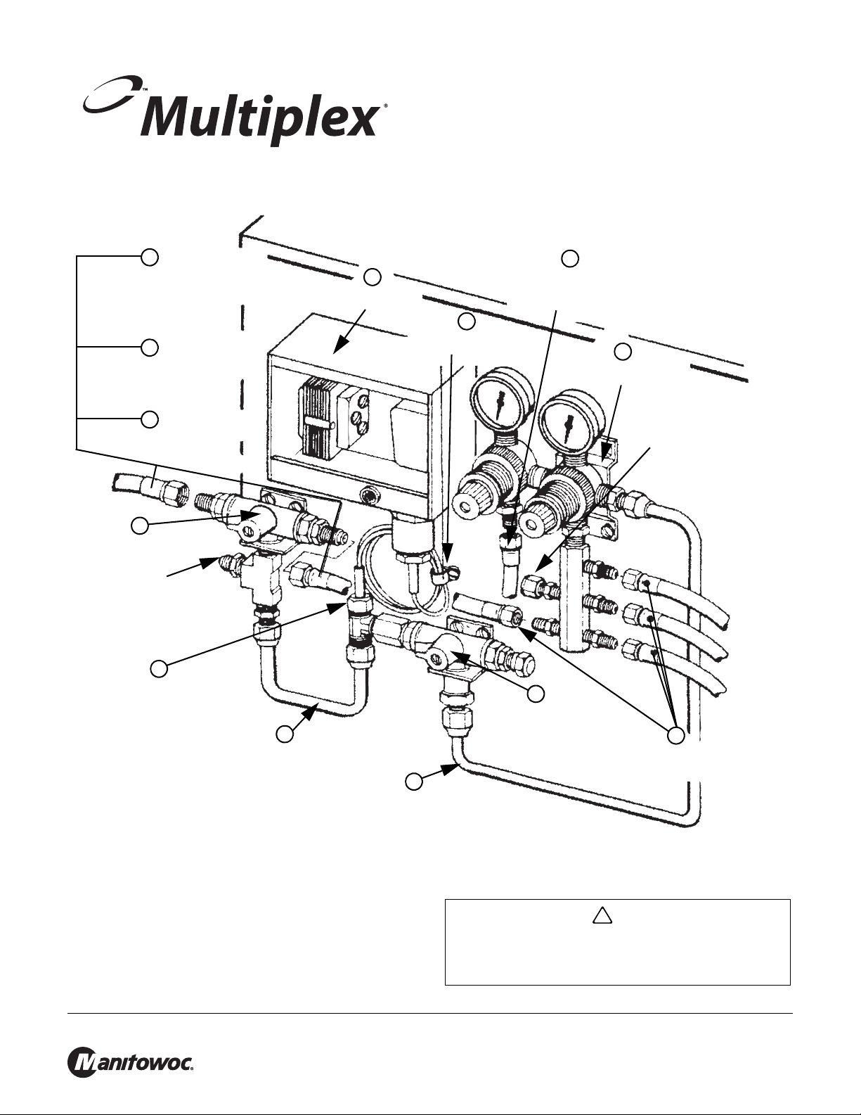
FIGURE 1
4
Low CO
2 Alarm
Assembly
10
Connect the fifth 61” CO
2
line to the low pressure
regulator if one of the
beverages is sugar free
8
Hold Down Clip for Cap
Tube of Pressure Control
1
Medium & Low Pressure
Regulator Assembly
If all Syrups are Sugar
Based, remove cap nut and
install fifth CO
2 line. Place
cap nut on outlet of low
pressure regulator outlet
9
Connect the four or five 61”
CO
2 gas lines to the medium
pressure regulator assembly
2
Air/CO
2 Changeover
Valve Assembly
5
Copper line assembly connecting the
medium & low pressure regulator
assembly to the Air/CO
2 changeover valve
6
Copper line assembly connecting the Air/CO
2
changeover valve assembly to the changeover
valve assembly for the CO
2 tanks 1&2
7
Nut connecting the pressure switch to
the Air/CO
2 changeover valve
assembly
Attach the CO2 line from the
carbonator tank of the
remote unit to the remaining
flare fitting of the CO
2 tank
1&2 change over valve
assembly
3
CO
2 Tank 1&2
changeover valve
assembly
13
Connect to power supply
11
Connect the remaining two
120” CO
2 lines to the two
outlets of the CO
2 tank 1&2
changeover valve
12
Attach the two primary CO
2
tank regulators to the 120”
CO
2 lines of thee CO2 tank
1&2 changeover valv e
assembly
!
Caution
Subject: SL282-84 C02 KIT - Export
00206960
12/09
INTRODUCTION
The CO
assemblies that must be attached to the front or back prepunched panels of either the Model 1 1 or 38 remote
refrigeration units. Follow numerical assembly sequence.
Manitowoc Foodservice Sellersburg, 2100 Future Drive, Sellersburg, IN 47172, Tel: 812-246-7000, www.manitowocbeverage.com
2 control kit consists of four basic pre-assembled
To Avoid Serious Injury Read the following warnings
before beginning an installation. Failure to do so may
result in possible death or serious injury.
Page 2
SL282-84 C02 KIT - Export 00206960
!
Warning
DO Adhere to all National and Local Plumbing and
DO Turn “Off” incoming electrical service switches
DO Check that all flare fittings on the carbonation
DO Inspect pressure on Regulators before starting
DO Protect eyes when working around refrigerants.
DO Use caution when handling metal surface
DO Handle CO
DO Stor e CO
Electrical Safety Codes.
when servicing, installing, or repairing
equipment.
tank(s) are tight. This check should be
performed with a wrench to ensure a quality
seal.
up equipment.
edges of all equipment.
2 cylinders and gauges with care.
Secure cylinders properly against abrasion.
2 cylinder(s) in well ventilated areas.
KIT INSTRUCTIONS
Refer to FIGURE 1 for the following procedures.
1. The medium and low pressure regulator assembly must
be attached to the panel by two sheet metal screws
diagonally .
2. The air/C0
2 changeover valve assembly must be
positioned at the bottom of the panel with two sheet metal
screws horizontally .
3. The CO
2 changeover valve assembly for the CO2 tanks
1& 2 must be positioned on the left and slightly above the
air/CO
2 changeover valve assembly with two sheet met al
screws horizontally .
4. The low CO
2 alarm assembly must be positioned on the
upper left side and attached with two sheet metal screws
diagonally to expose the two mounting holes. The cover
must be removed to expose the two mounting holes.
5. Connect the medium and low pressure regulator
assembly to the air/C0
2 changeover valve assembly by
using the longer of the two 1/4" copper tube assemblies.
6. Connect the air/C0
2 changeover assembly to the C02
tank changeover valve assembly by using the short “U”
shaped 1/4" copper tube assembly .
7. Connect the small copper cap tube extending from the
bottom of the C0
the tee fitting attached to the air/C0
2 control assembly box to the 1/4" MF of
2 changeover valve
assembly .
DO NOT Throw or drop a CO
DO NOT Connect the CO2 cylinder(s) directly to the
DO NOT Store CO
DO NOT Release CO
DO NOT T ouch Refrigeration lines inside units, some
cylinder(s) in an upright position with a chain.
product container. Doing so will result in an
explosion causing possible death or injury. Best
to connect the CO2 cylinder(s) to a regulator(s).
2 cylinders in temperature above 125˚
F (51. 7˚ C) near furnaces, radiator or sources
of heat.
may exceed temperatures of 200˚ F (93.3˚ C).
2 cylinder . Secure the
2 gas from old cylinder.
NOTE: Water pipe connections and fixtures directly connected to a
potable water supply shall be sized, installed and maintained in
accordance with Federal, State, and Local codes
DANGER OF ELECTRICAL SHOCK - Disconnect and
lock out all electrical power sources before performing
service or maintenance on this machine -- except when
electrical tests are being performed by qualified service
personnel.
.
8. Position the hold down clip over one section of copper
cap tube coil and attach clip to side of unit with sheet
metal screw .
9. Connect four or five 61" CO
2 gas lines to the 1/4" MF
fitting of the manifold assembly of the medium pressure
regulator.
NOTE: The fittings have check valves.
10. Connect the fifth 61" CO
2 line to the 1/4" MF fitting of the
low pressure regulator if one of the beverages is sugar
free. If all syrups are sugar based, remove the cap nut
from the remaining fitting of the medium pressure
regulator and attach the fifth CO
2 line. Install the cap nut
on the 1/4" MF fitting of the low pressure regulator.
1 1. Connect the two remaining 120" CO
CO
2 tank changeover valve. Att ach the C02 line
2 plastic lines to the
connected to the carbonator tank in the remote unit to the
remaining 1/4" MF fitting of the C0
2 tank changeover
valve assembly .
12. Attach the two CO
connect the two 120" CO
2 primary regulators to CO2 t anks then
2 lines from the C02 t ank
changeover valve assembly to the regulators. Do not
open the CO
quick disconnects to the five CO
2 tank valves at this time. Attach the C02 gas
2 gas plastic lines.
Manitowoc Foodservice Sellersburg, 2100 Future Drive, Sellersburg, IN 47172, Tel: 812-246-7000, www.manitowocbeverage.com
Page 3

SL282-84 C02 KIT - Export 00206960
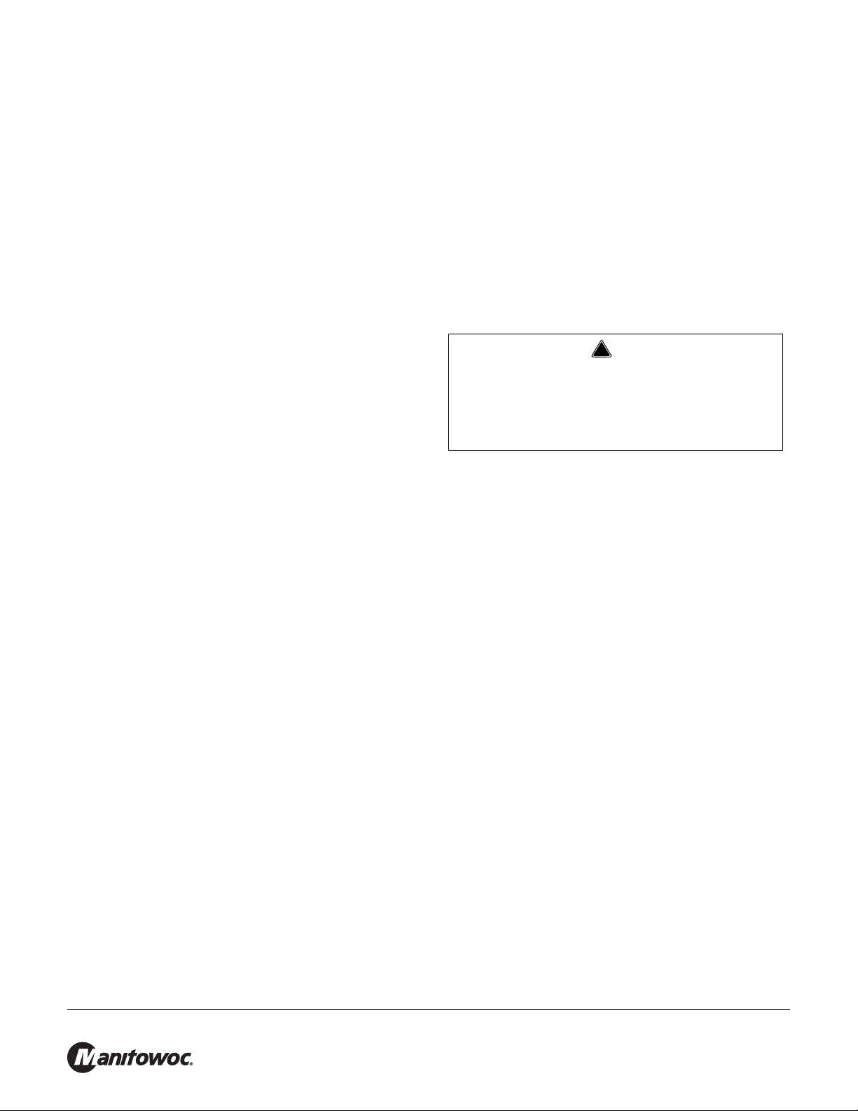
FIGURE 2
TRANS.
RED
GRD.
220
VOLTS
LIGHT
BLU
WHT
BUZZER
PRESSURE
SW.
T esting For CO2 Leaks
T o test the assembly to make Sure there are no leaks, the
CO
2 gas line previously installed from the carbonator t ank
to the CO
be removed. Remove the cap nut from the sir/CO
2 tank changeover valve assembly will have to
2
changeover valve. Turn the knob with the directional
pointer to the left, counterclockwise.
Screw the cap nut onto the 1/4" MF where the CO
2 line to
the carbonator was removed. Turn the knob with the
directional pointer to either CO
CO
2 cylinder . Adjust the primary regulator to 90 P.S.I., set
2 tank 1 or 2. Open that
the medium pressure regulator to 60 P.S.I, and set the
low pressure regulator to 14-16 P.S.I.
Allow the CO
minutes, then turn the CO
2 tank pressure to remain on fo r three
2 tank handle to the "OFF"
position. The CO
2 tank gauge should remain constant, no
drop in pressure.
If the CO
2 tank gauge drops in pressure, locate source of
leak and correct. A soap solution when applied to the
connections will pinpoint the leak.
Remove the cap nut, replace the CO
2 gas line from the
carbonator tank, and screw the cap nut back on the air/
CO
2 changeover valve.
13. Wire the electrical supply to the transformer as shown in
the wiring diagram in FIGURE 2. The CO
2 control
buzzer should sound and the lamp should illuminate
when the CO
2 pressure on the primary CO2 tank
regulator drops to 70 P. S. I. and shut of f when the
pressure reached 90 P.S.I.
Manitowoc Foodservice Sellersburg, 2100 Future Drive, Sellersburg, IN 47172, Tel: 812-246-7000, www.manitowocbeverage.com
 Loading...