

Multiplex SafetySwitch 12 HV M6, SafetySwitch 2 HV TwinBatt, SafetySwitch 12 HV TwinBatt M6, SafetySwitch 6 HV, SafetySwitch 12 HV Instructions Manual
Page 1
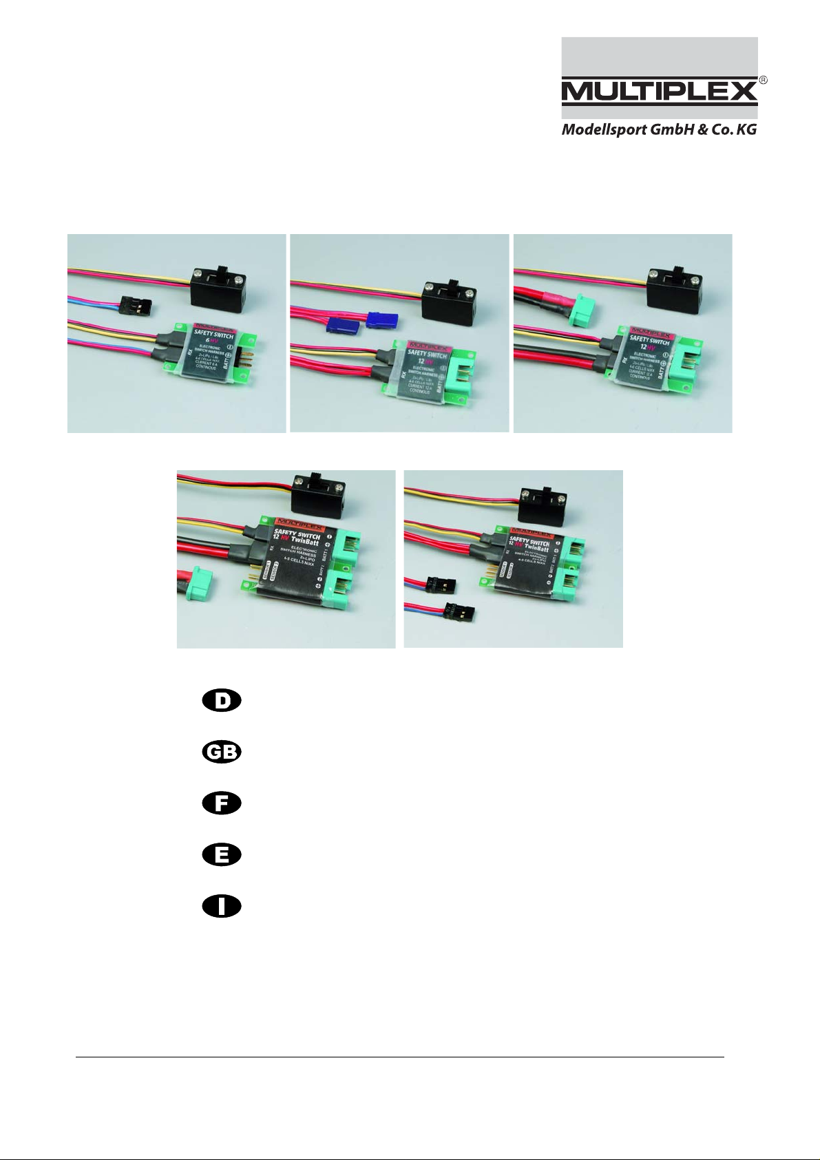
SafetySwitch 6/12 HV TwinBatt
6 HV 12 HV 12 HV M6
12 HV TwinBatt 12 HV TwinBatt M6
Rev.: 01.09.2010
Anleitung
Instructions
Instructions
Instrucciones
Istruzioni
2 – 3
4 – 5
6 – 7
8 – 9
10 – 11
© MULTIPLEX Modellsport GmbH & Co. KG Westliche Gewerbestr 1 D-75015 Bretten
GERMANY
Page 2
Anleitung SAFETY
SAFETY
SAFETY----SWITCH 12HV / 12HV (M6) / 12HV TwinBatt / 12HV TwinBatt (M6)
SAFETY SAFETY
Bedienungsanleitung
Bedienungsanleitung SAFETY
BedienungsanleitungBedienungsanleitung
SWITCH 12HV / 12HV (M6) / 12HV TwinBatt / 12HV TwinBatt (M6)
SWITCH 12HV / 12HV (M6) / 12HV TwinBatt / 12HV TwinBatt (M6)SWITCH 12HV / 12HV (M6) / 12HV TwinBatt / 12HV TwinBatt (M6)
! Diese Bedienungsanleitung ist Bestandteil des
Produktes. Sie beinhaltet wichtige Informationen
und Sicherheitshinweise. Sie ist deshalb jederzeit
griffbereit aufzubewahren und bei der Weitergabe
des Produktes an Dritte mitzugeben.
! Vor Inbetriebnahme Anleitung vollständig lesen!
1. M
ERKMALE UND FUNKTIONSWEISE
• Elektronisches Sicherheits-Schalterkabel
• Kompakte Bauweise und geringes Gewicht
• SMD-Technik, verschleißarm, vibrationsfest
• Hochwertige vergoldete Stecksysteme und große Kabel-
querschnitte
• Hohe Dauerstrombelastbarkeit
• Ausfallsicher: Bei einem Defekt am Schiebeschalter oder
dessen Anschlussleitung stellt die Elektronik sicher, dass der
zuletzt aktive Schaltzustand (EIN oder AUS) beibehalten
MULTIPLEX
wird. D.h. Selbst wenn der Schalter im Flug abvibriert ist die
Spannungsversorgung der RC-Anlage weiterhin sichergestellt.
• Zwei Empfänger-Anschlusskabel für doppelten Leitungs-
querschnitt und doppelte Kontaktzahl bei SAFETY-SWITCH
12HV / 12HV TwinBatt
• MPX M6 Hochstrom-Anschluss bei SAFETY-SWITCH
12HV (M6) / 12HV TwinBatt (M6) zum direkten Anschluss an
die MULTIPLEX Empfänger RX-9/12/16-DR pro M-LINK oder
RX-9/12-SYNTH DS M-PCM.
• Integrierte Akkuweiche bei SAFETY-SWITCH 12HV Twin-
Batt / 12HV TwinBatt (M6). Die Akkus werden gleichzeitig
und gleichmäßig entladen. Bei Ausfall eines Akkus übernimmt der zweite Akku die Empfängerstromversorgung allein.
• Zwei Sensoranschlüsse bei SAFETY-SWITCH 12HV Twin-
Batt, zur Erfassung beider Empfängerakkuspannungen während des Fluges. Dies ermöglicht eine genauere Beurteilung
des Zustandes der Empfängerakkus.
Das Schalterkabel ist ein sicherheitsrelevantes Bauteil in der
Empfänger-Stromversorgungskette. Konventionelle Schalterkabel mit rein mechanischen Schaltern stellen z.B. durch Alterungserscheinungen (Vibration, Abnutzung, Korrosion) an den
Schaltkontakten nach einer gewissen Verwendungsdauer ein
Sicherheitsrisiko durch Ausfall dar. Zudem steigen die Anforderungen an ein Schalterkabel durch den Leistungsbedarf moderner Hochleistungsservos. Viele konventionelle, rein mechanische
Schalterkabel sind dem nicht gewachsen.
Der/die Empfängerakku(s) wird/werden direkt an der Schalterplatine des SAFETY-SWITCH angeschlossen. Die Verbindung zum
Empfänger erfolgt über eine direkte kurze Stromführung ohne
mechanisches Schaltelement. Die Schaltfunktion wird von vibrationsfesten, ausfallsicheren Hochleistungs-FET´s übernommen,
die im Vergleich zu mechanischen Schaltern einen sehr geringen
Innenwiderstand aufweisen. In Verbindung mit hochwertigen
Goldkontakten und großen Kabelquerschnitten können die Servos ihre Leistungsfähigkeit erst richtig entfalten.
Als EIN / AUS-Schaltelement dient ein mechanischer Schiebeschalter, der lediglich den EIN / AUS-Schaltimpuls gibt. Der Laststrom fließt nicht über diesen Schalter. Sie können den Schalter
an beliebiger, gut zugänglicher Stelle im Modell installieren.
2. M
SAFETY-SWITCH 6HV / 12HV / 12HV (M6)/
-SWITCH 6 HV / 12 HV / 12 HV (M6) / 12HV TwinBatt / 12HV TwinBatt (M6) • # 82 5895 (10-02-25/BRAN) • Irrtum und Änderung vorbehalten! •
12HV T
ONTAGE UND INBETRIEBNAHME
WINBATT
/ 12HV T
WINBATT
(M6)
1. Befestigen Sie das Sicherheits-Schalterkabel SAFETYSWITCH möglichst vibrations- und stoßgeschützt im Modell.
2. SAFETY-SWITCH 6HV: Verbinden Sie das UNI-
SAFETY----SWITCH 6HV
SAFETYSAFETY
SWITCH 6HV
SWITCH 6HVSWITCH 6HV
Anschlusskabel (RX) mit dem Akku-Steckplatz Ihres Empfängers.
SAFETY-SWITCH 12HV / 12HV TwinBatt
: Schließen Sie das
zweite UNI-Anschlusskabel (RX) an einen beliebigen freien
Servosteckplatz oder ggf. den zweiten Akku-Steckplatz des
Empfängers an.
! Hinweis
Beim Anschließen der (des) UNI-Anschlusskabel(s) (RX) auf
korrekte Steckrichtung und insbesondere bei Fremdprodukten auf kompatible Kontaktbelegung achten:
SAFETY-SWITCH 12HV (M6) / 12HV TwinBatt (M6): Verbin-
den Sie das zweiadrige Anschlusskabel (RX) mit M6-Buchse
und den M6-Stecker des MULTIPLEX Empfängers RX9/12/16-DR pro M-LINK oder RX-9/12-SYNTH DS M-PCM.
3. Platzieren Sie den mechanischen EIN/AUS-Schiebeschalter
an einer beliebigen Stelle im Modell, möglichst geschützt vor
versehentlicher Betätigung.
Stecken Sie den/die 4 - 6 Zellen NiXX oder 2S LiXX Akkupack(s) an den/die mit „BATT“ bezeichneten Anschluss/ üsse des SAFETY-SWITCH an. Achten Sie auf korrekte Polung:
! Hinweis
Schließen Sie generell nur Komponenten an Ihren Emfpänger
an, die für die entsprechende Empfängerakkuspannung vorgesehen sind. (4 – 6 Zellen oder 2S LiXX)
! Hinweis
Bei der integrierten Akkuweiche handelt es sich um eine sichere, robuste und mit nur wenigen Bauteilen aufgebaute Diodenweiche. Der Spannungsabfall an der Akkuweiche beträgt
ca. 0,5 V.
! Hinweis
Verwenden Sie bei den SAFETY-SWITCH 12HV TwinBatt
nur typgleiche Akkus mit gleicher Kapazität, Spannungslage,
Alter und Leistungsfähigkeit.
• Stecksystem am SAFETY-SWITCH 6 HV:
MULTIPLEX MP-RC. Hierzu passend: Akkuanschlusskabel
MP-RC (# 8 5102) oder Buchse MP 3-Pol (# 8 5225).
• Stecksystem am SAFETY-SWITCH 12HV (M6) / 12HV
TwinBatt (M6): M6-Stecker.
Passend hierfür: Buchse M6 (# 8 5214).
4. Schalten Sie Ihren Sender EIN. Danach schalten Sie die
Stromversorgung Ihres Empfangssystems über das EIN/AUSSchaltelement des SAFETY-SWITCH EIN. Zum AUS schalten zuerst das EIN/AUS-Schaltelement des SAFETYSWITCH und erst danach den Sender ausschalten.
! Hinweis
Bei Bedarf können Sie die Anschlussleitung zum mechani-
schen EIN/AUS-Schiebeschalter beinahe beliebig verlängern.
5. Bei den Versionen 12HV TwinBatt / 12HV TwinBatt (M6)
kann, bei Verwendung eines telemetriefähigen Empfängers
und Senders, zusätzlich ein Spannungssensor (# 8 5400) an
den beiden 2-poligen UNI-Steckern der Platine angeschlossen werden. Verbinden Sie hierzu das mit dem Sensor gelieferte Sensor-Kabel mit einem der beiden Sensorstecker
(Sensor 1 / Sensor 2). Bei Verwendung eines zweiten Sensorkabels (# 8 5056) am Sensorausgang 2 des SAFETYSWITCH 12HV TwinBatt / 12HV TwinBatt (M6) können somit,
nach Freigabe des zweiten Messkanals, mittels MULTImate
(# 8 2094) oder Sensor DataManager, die Spannungswerte
beider Empfängerakkus an den Sender übertragen werden.
(z.B. ROYALpro)
MULTIPLEX Modellsport GmbH & Co.KG • Westliche Gewerbestraße 1 • D-75015 Bretten (Gölshausen) • www.multiplex-rc.de Seite 1/2
Page 3
Anleitung SAFETY
SAFETY
SAFETY----SWITCH 12HV / 12HV (M6) / 12HV TwinBatt / 12HV TwinBatt (M6)
SAFETY SAFETY
Bedienungsanleitung
Bedienungsanleitung SAFETY
BedienungsanleitungBedienungsanleitung
SWITCH 12HV / 12HV (M6) / 12HV TwinBatt / 12HV TwinBatt (M6)
SWITCH 12HV / 12HV (M6) / 12HV TwinBatt / 12HV TwinBatt (M6)SWITCH 12HV / 12HV (M6) / 12HV TwinBatt / 12HV TwinBatt (M6)
! Hinweis
Wir empfehlen den Einsatz der SAFETY-SWITCH 6HV in
Modellen bis hin zu 6 Standard- oder 4 Digital-/ Hochleistungs-Servos. Darüber hinaus sollten SAFETYSWITCH 12HV oder SAFETY-SWITCH 12HV TwinBatt
verwendet werden.
! Hinweis
Verwenden Sie aus Gründen der Sicherheit bei den SAFETYSWITCH TwinBatt zusätzlich einen Peak-Filter (# 8 5180). Da
durch die Sperrwirkung der Akkuweichen-Dioden eventuelle,
insbesondere durch Hochleistungsservos induzierte, Spannungsspitzen nicht von den Empfängerakkus gepuffert werden können.
3. T
ECHNISCHE DATEN
SAFETY-SWITCH 6HV 12HV 12HV (M6)
Best.-Nr:
MULTIPLEX
Zellenzahl: 2S LiPo / LiXX oder 4 – 6 NiXX Zellen
Zulässiger Dauer-
strom:
Ruhestrom-
aufnahme*:
Empfänger-
Anschluss:
Akku-Anschluss:
Abmessungen
(L x B x H):
Gewicht:
(mit Kabel)
Besonderheiten
!
Hinweis
# 8 5006 # 8 5007 # 8 5008 # 8 5009 # 8 5010
max. 6 A max. 12 A
ca. 2,5 mA (im AUS-Zustand)
1 x 0,33
mm
UNI ca. 200
mm lang
MPX MP-
RC-
Stecker
ca.
38 x 28 x 6
mm
ca. 20 g ca. 25 g ca. 30 g ca. 35g ca. 35 g
2
2 x 0,33
2
mm
UNI ca. 200
mm lang
MPX M6-
Stecker
ca.
38 x 28 x 6
mm
1 x 2,5
mm2
M6 ca. 200
mm lang
MPX M6-
Stecker
38 x 28 x 6
mm
* Der genannte Ruhestrom fließt in der AUS Stellung des mechanischen Schiebeschalters. Ziehen Sie daher den Empfängerakku bei längerer Lagerung des Modells vom SAFETY-SWITCH
ab! Auf diese Weise beugen Sie einer eventuellen Tiefentladung
des Empfängerakkus vor.
ca.
12HV Twin-
Batt
2 x 0,33
mm2
UNI ca. 200
mm lang
2 x MPX M6
Stecker
ca.
50 x 40 x 10
mm
Akkuweiche/
2 Sensoran-
schlüsse [V]
12HV Twin-
Batt (M6)
1 x 2,5
mm2
M6 ca. 200
mm lang
2 x MPX M6
Stecker
ca.
50 x 40 x 10
mm
Akkuweiche/
2 Sensoran-
schlüsse [V]
SAFETY----SWITCH 6HV
SAFETYSAFETY
SWITCH 6HV
SWITCH 6HVSWITCH 6HV
4. G
EWÄHRLEISTUNG
Die Firma MULTIPLEX Modellsport GmbH & Co.KG übernimmt
keinerlei Haftung für Verluste, Schäden oder Kosten, die sich aus
fehlerhafter Verwendung und Betrieb ergeben oder in irgendeiner
Weise damit zusammenhängen. Soweit gesetzlich zulässig, ist
die Verpflichtung der Firma MULTIPLEX Modellsport GmbH &
Co.KG zur Leistung von Schadenersatz, gleich aus welchem
Rechtsgrund, begrenzt auf den Rechnungswert der an dem
schadenstiftenden Ereignis unmittelbar beteiligten Warenmenge
der Firma MULTIPLEX Modellsport GmbH & Co.KG. Dies gilt
nicht, soweit die MULTIPLEX Modellsport GmbH & Co.KG nach
zwingenden gesetzlichen Vorschriften wegen Vorsatzes oder
grober Fahrlässigkeit unbeschränkt haftet.
Für unsere Produkte leisten wir entsprechend den derzeit
geltenden gesetzlichen Bestimmungen Gewähr. Wenden Sie
sich mit Gewährleistungsfällen an den Fachhändler, bei dem Sie
das Produkt erworben haben.
Von der Gewährleistung ausgeschlossen sind Fehlfunktionen,
die verursacht wurden durch:
• Unsachgemäßen Betrieb
• Falsche, nicht oder verspätet, oder nicht von einer autori-
sierten Stelle durchgeführte Wartung
• Falsche Anschlüsse
• Verwendung von nicht originalem MULTIPLEX-Zubehör
• Veränderungen / Reparaturen, die nicht von MULTIPLEX
oder einer MULTIPLEX-Servicestelle ausgeführt wurden
• Versehentliche oder absichtliche Beschädigungen
• Defekte, die sich aus der normalen Abnutzung ergeben
• Betrieb außerhalb der technischen Spezifikationen oder im
Zusammenhang mit Komponenten anderer Hersteller.
5. CE-K
ONFORMITÄTSERKLÄRUNG
Die Bewertung des Gerätes erfolgte nach europäisch
harmonisierten Richtlinien.
Sie besitzen daher ein Produkt, das hinsichtlich der Konstruktion
die Schutzziele der Europäischen Gemeinschaft zum sicheren
Betrieb der Geräte erfüllt.
Die ausführliche CE-Konformitätserklärung finden Sie als PDFDatei im Internet bei www.multiplex-rc.de im Bereich
DOWNLOADS unter PRODUKT-INFOS.
6. E
NTSORGUNGSHINWEISE
Elektrogeräte, die mit der durchgestrichenen Mülltonne
gekennzeichnet sind, zur Entsorgung nicht in den Hausmüll geben, sondern einem geeigneten Entsorgungssystem zuführen.
In Ländern der EU (Europäische Union) dürfen Elektrogeräte
nicht durch den Haus- bzw. Restmüll entsorgt werden (WEEE Waste of Electrical and Electronic Equipment, Richtlinie
2002/96/EG). Sie können Ihr Altgerät bei öffentlichen Sammelstellen Ihrer Gemeinde bzw. Ihres Wohnortes (z.B. Recyclinghöfe) abgeben. Das Gerät wird dort für Sie fachgerecht und kostenlos entsorgt.
Mit der Rückgabe Ihres Altgerätes leisten Sie einen wichtigen
Beitrag zum Schutz der Umwelt!
-SWITCH 6 HV / 12 HV / 12 HV (M6) / 12HV TwinBatt / 12HV TwinBatt (M6) • # 82 5895 (10-02-25/BRAN) • Irrtum und Änderung vorbehalten! •
MULTIPLEX Modellsport GmbH & Co.KG • Westliche Gewerbestraße 1 • D-75015 Bretten (Gölshausen) • www.multiplex-rc.de Seite 2/2
Page 4
Operating instructions SAFETY
SAFETY
Operating instructions SAFETY
Operating instructions SAFETY----SWITCH 6HV
Operating instructions SAFETYOperating instructions SAFETY
SAFETY----SWITCH 12HV / 12HV (M6) / 12HV TwinBatt / 12HV TwinBatt (M6)
SAFETY SAFETY
SWITCH 12HV / 12HV (M6) / 12HV TwinBatt / 12HV TwinBatt (M6)
SWITCH 12HV / 12HV (M6) / 12HV TwinBatt / 12HV TwinBatt (M6)SWITCH 12HV / 12HV (M6) / 12HV TwinBatt / 12HV TwinBatt (M6)
! These operating instructions are an integral part
of the product, and contain important information
and safety notes. Store them in a safe place, and be
sure to pass them on to the new owner if you
dispose of the product.
! Read right through the instructions before use!
1. F
EATURES
, M
ETHOD OF WORKING
• Electronic safety switch harness
• Compact design, low weight
• SMT construction, low-wear, vibration-proof
• High-quality gold-plated connector systems and large con-
ductor cross-sections
• High continuous current capacity
MULTIPLEX
• Failure-proof: if a fault develops in the slide switch or its con-
necting leads, the electronic circuit ensures that the last
active switched stage (ON or OFF) is maintained. This
means: even if the switch comes adrift in flight due to
vibration, the power supply to the RC system is reliably
maintained.
• Two receiver leads provide double the conductor cross-
section and twice the number of contacts in the case of the
SAFETY-SWITCH 12HV / 12HV TwinBatt.
• MPX M6 high-current connector on the SAFETY-SWITCH
12HV (M6) / 12HV TwinBatt (M6) for direct connection to
MULTIPLEX RX-9/12/16-DR pro M-LINK or RX-9/12-SYNTH
DS M-PCM receivers.
• Integral battery backer in the case of the SAFETY-SWITCH
12HV TwinBatt / 12HV TwinBatt (M6). Both batteries are
discharged simultaneously and evenly. If one battery should
fail, the second pack powers the receiving system on its own.
• Two sensor sockets on the SAFETY-SWITCH 12HV
TwinBatt, for monitoring the voltage of both receiver batteries
in flight. This provides a more accurate method of assessing
the state of the receiver battery while the model is flying.
The switch harness is an important safety-relevant component in
the receiving system power supply chain. After a certain period of
use, conventional switch harnesses with purely mechanical
switches represent a security risk due to ageing effects such as
vibration, wear and corrosion. What is more, the demands placed
on switch harnesses are rising due to the power requirements of
modern high-performance servos. Many conventional, purely
mechanical switches are simply not up to the job.
The receiver battery or batteries are connected directly to the
SAFETY-SWITCH circuit board. The unit is connected directly to
the receiver by a short cable which features no mechanical
switch element. The switching function is carried out by
extremely reliable, vibration-proof, high-performance FETs, which
exhibit very low internal resistance compared with mechanical
switches. In conjunction with high-quality gold-contact connectors
and cables of generous cross-section it is finally possible to
exploit the full performance potential of modern servos.
A mechanical slide switch acts as the ON / OFF switch element,
but all it does is provide the ON / OFF switching signal. The load
current does not flow through this switch. The switch can be
installed in any easily accessible position in the model.
-SWITCH 6 HV / 12 HV / 12 HV (M6) / 12HV TwinBatt / 12HV TwinBatt (M6) • # 82 5895 (10-02-25/BRAN) • Errors and omissions expected! •
2. I
NSTALLATION
, F
IRST USE
SAFETY-SWITCH 6HV / 12HV / 12HV (M6) /
12HV T
1. Mount the SAFETY-SWITCH harness in the model in a
2. SAFETY-SWITCH 6HV: connect the UNI lead (RX) to your
WINBATT
/ 12HV T
WINBATT
(M6)
position where it is well protected from vibration and shock.
receiver’s battery socket.
SWITCH 6HV
SWITCH 6HVSWITCH 6HV
SAFETY-SWITCH 12HV / 12HV TwinBatt
: connect the
second UNI lead (RX) to any vacant servo socket on the
receiver, or - if present - the receiver’s second battery socket.
! Note
When connecting the UNI lead(s) (RX) please take care to
maintain correct polarity; this applies in particular to the pin
assignment of other makes of equipment:
SAFETY-SWITCH 12HV (M6) / 12HV TwinBatt (M6): connect
the two-core lead (RX) terminating in an M6 socket to the M6
connector on the MULTIPLEX RX-9/12/16-DR pro M-LINK or
RX-9/12-SYNTH DS M-PCM receiver.
3. Install the mechanical ON/OFF slide-switch in any convenient position in the model, if possible protected from
accidental actuation.
Connect the 4 - 6 NiXX cells or 2S LiXX battery pack(s) to the
socket(s) marked “BATT” on the SAFETY-SWITCH. Take
care to maintain correct polarity:
! Note
The basic rule is that you should only connect components to
your receiver which are designed for the voltage of the
receiver battery you are using (4 – 6 cells or 2S LiXX).
! Note
The integral battery backer is a reliable, robust diode type
consisting of few components. The voltage drop across the
backer is around 0.5 V.
! Note
The SAFETY-SWITCH 12HV TwinBatt should only ever be
used with two identical batteries: same type, capacity, voltage
curve, age and performance.
• Connector system on the SAFETY-SWITCH 6 HV:
MULTIPLEX MP-RC. Matching connectors: MP-RC battery
lead (# 8 5102) or MP 3-pin socket (# 8 5225).
• Connector system on the SAFETY-SWITCH 12HV (M6) /
12HV TwinBatt (M6): M6 plug.
Matching connector: M6 socket (# 8 5214).
4. Switch your transmitter ON, then switch your receiving
system’s power supply ON using the SAFETY-SWITCH’S
ON/OFF switching element. When switching OFF: first
operate the SAFETY-SWITCH’S ON/OFF switching element,
and only then switch the transmitter off.
! Note
The lead to the mechanical ON/OFF slide-switch can be
extended to any length if necessary.
5. If you are using a telemetry-capable receiver and transmitter
together with one of the 12HV TwinBatt / 12HV TwinBatt (M6)
versions it is possible to connect a voltage sensor (# 8 5400)
to one of the two 2-pin UNI sockets on the circuit board; this
is accomplished by connecting the sensor lead (supplied with
the sensor) to one of the two sensor sockets
(Sensor 1 / Sensor 2). If you connect a second sensor lead
(# 8 5056) to sensor output 2 on the SAFETY-SWITCH 12HV
TwinBatt / 12HV TwinBatt (M6), you can transmit the voltage
values for both receiver batteries to the transmitter (e.g.
ROYALpro) after activating the second measuring channel;
this is carried out using a MULTImate (# 8 2094) or Sensor
DataManager.
MULTIPLEX Modellsport GmbH & Co.KG • Westliche Gewerbestraße 1 • D-75015 Bretten (Gölshausen) • www.multiplex-rc.de Page 1/2
Page 5

Operating instructions SAFETY
SAFETY
Operating instructions SAFETY
Operating instructions SAFETY----SWITCH 6HV
Operating instructions SAFETYOperating instructions SAFETY
SAFETY----SWITCH 12HV / 12HV (M6) / 12HV TwinBatt / 12HV TwinBatt (M6)
SAFETY SAFETY
SWITCH 12HV / 12HV (M6) / 12HV TwinBatt / 12HV TwinBatt (M6)
SWITCH 12HV / 12HV (M6) / 12HV TwinBatt / 12HV TwinBatt (M6)SWITCH 12HV / 12HV (M6) / 12HV TwinBatt / 12HV TwinBatt (M6)
! Note
We recommend the use of the SAFETY-SWITCH 6HV in
models fitted with up to six standard or four digital / highperformance servos. Above this number you should use
the SAFETY-SWITCH 12HV or SAFETY-SWITCH 12HV
TwinBatt.
! Note
For safety reasons we also recommend the use of a Peak
Filter (# 8 5180) in conjunction with the SAFETY-SWITCH
TwinBatt, as voltage peaks which may be induced by highperformance servos cannot be buffered from the receiver
batteries due to the blocking action of the battery backer
diodes.
3. S
PECIFICATION
MULTIPLEX
SAFETY-SWITCH 6HV 12HV 12HV (M6)
Order No:
Cell count: 2S LiPo / LiXX or 4 – 6 NiXX cells
Permissible con-
tinuous current:
Idle current
drain*:
Receiver lead:
Battery
connectors:
Dimensions
(L x W x H):
Weight:
(incl. leads)
Special features
!
Note
12HV
TwinBatt
# 8 5006 # 8 5007 # 8 5008 # 8 5009 # 8 5010
max. 6 A max. 12 A
approx. 2.5 mA (in OFF state)
1 x 0.33
mm
UNI ap-
prox. 200
mm long
MPX MP-
RC plug
approx.
38 x 28 x 6
mm
approx.
20 g
2
2 x 0.33
2
mm
UNI ap-
prox. 200
mm long
MPX M6
plug
approx.
38 x 28 x 6
mm
approx.
25 g
1 x 2.5
mm2
M6 approx.
200 mm
long
MPX M6
plug
approx.
38 x 28 x 6
mm
approx.
30 g
2 x 0.33
mm2
UNI approx.
200 mm
long
2 x MPX M6
plug
approx.
50 x 40 x 10
mm
approx.
35 g
Battery
backer /
2 sensor
sockets [V]
12HV Twin-
Batt (M6)
1 x 2.5
mm2
M6 approx.
200 mm
long
2 x MPX M6
plug
approx.
50 x 40 x 10
mm
approx.
35 g
Battery
backer /
2 sensor
sockets [V]
* The stated idle current flows when the mechanical slide switch
is in the OFF position. For this reason you should always
disconnect the receiver battery from the SAFETY-SWITCH if the
model is to be stored for a long period. This will prevent any risk
of the receiver battery becoming deep-discharged.
SWITCH 6HV
SWITCH 6HVSWITCH 6HV
4. G
UARANTEE
/ L
IABILITY EXCLUSION
The company MULTIPLEX Modellsport GmbH & Co.KG accepts
no liability of any kind for loss, damage or costs which are due to
the incorrect use and operation of this product, or which are
connected with such operation in any way. Unless the law
expressly states otherwise, the liability on the part of MULTIPLEX
Modellsport GmbH & Co.KG to pay damages, regardless of the
legal argument employed, is limited to the invoice value of those
products supplied by MULTIPLEX Modellsport GmbH & Co.KG
which were directly involved in the event in which the damage
occurred. This does not apply if liability is incurred according to
statutory law on account of intentional or gross negligence.
We guarantee our products in accordance with the currently valid
statutory regulations. If you wish to make a claim under
guarantee, your initial course of action should always be to contact the dealer from whom you purchased the equipment.
The guarantee does not cover faults and malfunctions which are
caused by the following:
• Incorrect or incompetent use
• Maintenance carried out incorrectly, belatedly or not at all,
or not carried out by an authorised Service Centre
• Incorrect connections
• The use of accessories other than genuine MULTIPLEX
items
• Modifications or repairs which were not carried out by
MULTIPLEX or by an authorised MULTIPLEX Service
Centre
• Accidental or intentional damage
• Defects due to normal wear and tear
• Operation of the unit outside the limits stated in the
specification
• Operation of the unit in conjunction with equipment made by
other manufacturers.
5. CE C
ONFORMITY DECLARATION
This device has been assessed and approved in
accordance with European harmonised directives.
This means that you possess a product whose design and
construction fulfil the protective aims of the European Community
designed to ensure the safe operation of equipment.
The detailed CE conformity declaration can be downloaded in the
form of a PDF file from the Internet under www.multiplex-rc.de. It
is located in the DOWNLOADS area under PRODUKTINFOS.
6. D
ISPOSAL NOTES
Electrical equipment marked with the cancelled waste bin
symbol must not be discarded in the standard household
waste; instead it should be taken to a suitable specialist
disposal system.
In the countries of the EU (European Union) electrical
equipment must not be discarded via the normal domestic refuse
system (WEEE - Waste of Electrical and Electronic Equipment,
Directive 2002/96/EG). You can take unwanted equipment to
your nearest local authority waste collection point or recycling
centre. There the equipment will be disposed of correctly and at
no cost to you.
-SWITCH 6 HV / 12 HV / 12 HV (M6) / 12HV TwinBatt / 12HV TwinBatt (M6) • # 82 5895 (10-02-25/BRAN) • Errors and omissions expected! •
By returning your unwanted equipment you can make an
important contribution to the protection of the environment!
MULTIPLEX Modellsport GmbH & Co.KG • Westliche Gewerbestraße 1 • D-75015 Bretten (Gölshausen) • www.multiplex-rc.de Page 2/2
Page 6

Notice d’utilisation de SAFETY
SAFETY
! Cette instruction fait partie intégrante du produit. Celle-
ci contient des informations importantes ainsi que des
consignes de sécurités. Elle doit donc être consultable à
tous moments et à joindre lors d’une revente à tierces personnes
! A lire complètement avant utilisation!
1.
C
ARACTERISTIQUES ET MODE DE FONCTIONNMENT
• Interrupteur électronique de sécurité
• Construction compacte et faible poids
• Technologie CMS, très faible usure, résistant aux vibra-
tions
• Système de prise à contacts dorés de grande qualité et de
MULTIPLEX
grandes sections de câbles
• Courant permanent admissible très élevé
• Système sécurisé: lors d’un problème avec l’interrupteur où
ses câbles d’alimentations, l’électronique vous garanti que la
dernière position active reconnue (MARCHE ou ARRET) sera
maintenue. De ce fait, pendant le vol, même si l’interrupteur
se déconnecte à cause des vibrations, l’alimentation de
l’ensemble de réception est maintenue.
• Double câble d’alimentation de récepteur pour une double
section de câble et double nombre de contacts pour le
SAFETY-SWITCH 12HV / 12HV TwinBatt
• Prise pour courant élevé MPX M6 sur le SAFETY-SWITCH
12HV (M6) / 12HV TwinBatt (M6) pour le branchement direct
au récepteur MULTIPLEX RX-9/12/16-DR pro M-LINK ou RX9/12-SYNTH DS M-PCM.
• Aiguilleur d’accu intégré pour le SAFETY-SWITCH 12HV
TwinBatt / 12HV TwinBatt (M6). Les accus se vident en
même temps et de même manière. Lorsqu’un accu tombe en
panne le deuxième prend le relais et alimente le récepteur.
• Deux prises pour capteurs pour le SAFETY-SWITCH 12HV
TwinBatt, permettant la mesure des tensions des deux accus
de réceptions pendant le vol. Cela vous permet d’avoir une
information précise sur l’état de vos accus de réceptions.
L’interrupteur est un élément de sécurité très important dans la
chaine d’alimentation de votre système de réception. Les interrupteurs conventionnels composés uniquement de parties mécaniques peuvent tomber en panne, par ex. par vieillissement (vibrations, usure, corrosion), suite à des défauts de contacts après
un certain temps d’utilisation, il y a donc un risque au niveau sécurité. De plus, les exigences augmentent également au niveau
puissance nécessaire lors de l’utilisation de servos de puissances modernes. Beaucoup d’interrupteurs conventionnels, purement mécanique, ne sont pas de taille à répondre à ces besoins.
Le/les accu(s) de réception sont directement branchés sur le
SAFETY-SWITCH. L’alimentation du récepteur se fait directement au travers du circuit de puissance sans passer par des
éléments mécaniques de commutation. La commutation se fait
par des FET de puissance insensibles aux vibrations, et, comparé aux interrupteurs mécaniques, ont une résistance interne très
faible. Avec ses contacts dorés et ses grandes sections de câbles, les servos peuvent ainsi montrer leur vraie puissance.
Un interrupteur mécanique sert d’élément de commutation
MARCHE/ARRET qui en fait ne livre que l’impulsion de commande MARCHE/ARRET. Le courant de charge ne passe pas
-SWITCH 6 HV / 12 HV / 12 HV (M6) / 12HV TwinBatt / 12HV TwinBatt (M6) • # 82 5895 (10-02-25/BRAN) • I sous réserve d’erreur ou modifications! •
par cet interrupteur. Vous pouvez installer cet interrupteur à
n’importe quel endroit facilement accessible de votre modèle.
SAFETY----SWITCH 12HV / 12HV (M6) / 12HV TwinBatt / 12HV TwinBatt (M6)
SAFETY SAFETY
Notice d’utilisation de SAFETY
Notice d’utilisation de SAFETY----SWITCH 6HV
Notice d’utilisation de SAFETYNotice d’utilisation de SAFETY
SWITCH 12HV / 12HV (M6) / 12HV TwinBatt / 12HV TwinBatt (M6)
SWITCH 12HV / 12HV (M6) / 12HV TwinBatt / 12HV TwinBatt (M6)SWITCH 12HV / 12HV (M6) / 12HV TwinBatt / 12HV TwinBatt (M6)
SWITCH 6HV
SWITCH 6HVSWITCH 6HV
2. SAFETY-SWITCH 6HV
(RX) sur la prise d’alimentation accu de votre récepteur.
SAFETY-SWITCH 12HV / 12HV TwinBatt: branchez le second câble d’alimentation UNI (RX) sur une sortie de servo
ou, si disponible, une deuxième prise d’accu de réception.
! Remarque
Lors du branchement du (des) câble(s) de liaison(s) UNI (RX)
veillez à respecter le sens de branchement surtout pour les
produit d‘une autre marque, vérifiez leur compatibilité de
branchement:
SAFETY-SWITCH 12HV (M6) / 12HV TwinBatt (M6): bran-
chez le câble d’alimentation bifilaire (RX) avec le connecteur
M6 sur la prise M6 du récepteur MULTIPLEX RX-9/12/16-DR
pro M-LINK ou RX-9/12-SYNTH DS M-PCM.
3. Placez l’interrupteur mécanique MARCHE/ARRET à un endroit de votre choix dans le modèle, bien protégé afin d’éviter
des manipulations involontaires.
Branchez le pack d’accu de 4 à 6 éléments NiXX ou 2S LiXX
sur la(les) prise(s) référencées „BATT“ de votre SAFETYSWITCH. Veillez à respecter la bonne polarité:
! Remarque
D’une manière générale, ne branchez à votre récepteur que
des éléments compatibles avec la tension de votre accu de
réception utilisé (4 à 6 éléments NiXX ou 2S LiXX)
! Remarque
Concernant l’aiguilleur d’accu intégré, il s’agit d’un aiguillage
à diodes sûr, robuste et composé de peu de pièces. La chute
de tension au travers de cet aiguilleur est d’environ 0,5 V.
! Remarque
Pour le SAFETY-SWITCH 12HV TwinBatt n’utilisez que des
accus du même type et de même capacité, plage de tension,
âge et puissance.
• Système de connexion sur le SAFETY-SWITCH 6 HV:
MULTIPLEX MP-RC. Pour cela: les câbles d’alimentations
pour accus MP-RC (# 8 5102) ou prise MP 3-Pol (# 8 5225)
sont bien adaptés.
• Système de connexion sur le SAFETY-SWITCH 12HV (M6)
/ 12HV TwinBatt (M6): prise M6.
Pour cela: le connecteur M6 (# 8 5214) est bien adapté.
4. Mettez en marche votre émetteur. Ensuite branchez
l’alimentation de votre système de réception à l’aide de
l’interrupteur MARCHE/ARRET de votre SAFETY-SWITCH.
Pour l’arrêt de l’ensemble, arrêtez d’abord votre SAFETYSWITCH au travers de l’interrupteur MARCHE/ARRET puis
arrêtez votre émetteur.
! Remarque
Si nécessaire vous pouvez rallonger, presque autant que
vous souhaitez, le câble de votre interrupteur mécanique
MARCHE/ARRET.
5. Pour la version 12HV TwinBatt / 12HV TwinBatt (M6) vous
pouvez, en utilisant un récepteur et émetteur compatible télémétrie, brancher un capteur de tension (# 8 5400) sur chacune des prises UNI 2 pôles de la platine. Pour cela relier le
câble livré avec le capteur avec une des deux prises pour
capteur (Sensor 1 / Sensor 2). Si vous utilisez un deuxième
câble pour capteur (# 8 5056) branchez celui-ci à la sortie
pour capteur 2 de votre SAFETY-SWITCH 12HV TwinBatt /
12HV TwinBatt (M6), vous pouvez alors transmettre les va-
: branchez le câble d’alimentation UNI
leurs des tensions des deux accus de réception à votre émet-
2. M
SAFETY-SWITCH 6HV / 12HV / 12HV (M6)/
12HV T
ONTAGE ET UTILISATION
WINBATT
/ 12HV T
WINBATT
teur (par ex. : ROYALpro) une fois que vous aurez activé le
deuxième canal de mesure à l’aide du MULTImate (# 8 2094)
(M6)
ou du Sensor DataManager.
1. Fixez cet interrupteur électronique de sécurité SAFETYSWITCH dans un endroit du modèle protégé contre les vibrations et les chocs.
MULTIPLEX Modellsport GmbH & Co.KG • Westliche Gewerbestraße 1 • D-75015 Bretten (Gölshausen) • www.multiplex-rc.de Page 1/2
Page 7

Notice d’utilisation de SAFETY
SAFETY
SAFETY----SWITCH 12HV / 12HV (M6) / 12HV TwinBatt / 12HV TwinBatt (M6)
SAFETY SAFETY
Notice d’utilisation de SAFETY
Notice d’utilisation de SAFETY----SWITCH 6HV
Notice d’utilisation de SAFETYNotice d’utilisation de SAFETY
SWITCH 12HV / 12HV (M6) / 12HV TwinBatt / 12HV TwinBatt (M6)
SWITCH 12HV / 12HV (M6) / 12HV TwinBatt / 12HV TwinBatt (M6)SWITCH 12HV / 12HV (M6) / 12HV TwinBatt / 12HV TwinBatt (M6)
! Remarque
Nous conseillons l’utilisation des SAFETY-SWITCH 6HV
pour les modèles utilisant jusqu’à 6 servos standards ou
4 servos digitaux de grande puissance. Pour un nombre
plus important, il est conseillé d’utiliser des SAFETYSWITCH 12HV ou SAFETY-SWITCH 12HV TwinBatt.
! Remarque
Pour des raisons de sécurités, utilisez un filtre Peak
(# 8 5180) avec votre SAFETY-SWITCH TwinBatt. Du fait de
l’effet de blocage des diodes de l’aiguilleur d’accu, aidé par
les servos de grande puissance, des pointes de tensions sont
induits, ne pouvant pas êtres absorbés par le récepteur.
3. D
MULTIPLEX
ONNÉES TECHNIQUES
SAFETY-SWITCH 6HV 12HV 12HV (M6)
Nr. Com.:
Nbr d’éléments: 2S LiPo / LiXX ou 4 – 6 éléments NiXX
Courant perma-
nent autorisé:
Consommation
de courant au
repos*:
Prise pour récepteur:
Prise pour accu:
Dimensions
(L x B x H):
Poids:
(avec câble)
Particularité
!
Remarque
# 8 5006 # 8 5007 # 8 5008 # 8 5009 # 8 5010
max. 6 A max. 12 A
env. 2,5 mA (en mode OFF)
1 x 0,33
mm
UNI long.
env. 200
mm
Prise MPX
MP-RC
env.
38 x 28 x 6
mm
env. 20 g env. 25 g env. 30 g env. 35g env. 35 g
2
2 x 0,33
2
mm
UNI long.
env. 200
mm
Prise MPX
M6
env.
38 x 28 x 6
mm
1 x 2,5
mm2
M6 long.
env. 200
mm
Prise MPX
M6
env.
38 x 28 x 6
mm
* Le soit disant courant au repos passe par l’interrupteur mécanique lors qu’il est en position OFF. De ce fait, débranchez l’accu
de réception du SAFETY-SWITCH lorsque vous n’utilisez plus
votre modèle pendant un certain temps! Ainsi vous éviterez de
détériorer votre accu de réception suite à une décharge trop importante.
-SWITCH 6 HV / 12 HV / 12 HV (M6) / 12HV TwinBatt / 12HV TwinBatt (M6) • # 82 5895 (10-02-25/BRAN) • I sous réserve d’erreur ou modifications! •
12HV
TwinBatt
2 x 0,33
mm2
UNI long.
env. 200
mm
2 x prises
MPX M6
env.
50 x 40 x 10
mm
Aiguillage
d’accu/
2 prises
pour cap-
teur [V]
12HV Twin-
Batt (M6)
1 x 2,5
mm2
M6 long.
env. 200
mm
2 x Prises
MPX M6
env.
50 x 40 x 10
mm
Aiguillage
d’accu/
2 prises
pour cap-
teur [V]
SWITCH 6HV
SWITCH 6HVSWITCH 6HV
4. G
ARANTIE
/ R
ESPONSABILITE
La société MULTIPLEX Modellsport GmbH & Co.KG ne garantie
en aucun cas ce produit en cas de perte, de détérioration ou de
coûts survenant à une utilisation non conforme du matériel ou
des conséquences de celle-ci. En fonction des textes de lois, la
société MULTIPLEX Modellsport GmbH & Co.KG est tenue au
remboursement, quelque soit la raison, pour une valeur maximum correspondant à la valeur des pièces de la société
MULTIPLEX Modellsport GmbH & Co.KG mises en causes lors
de l’achat. Cela est valable, que dans les limites prévues par les
textes légaux concernant une grossière négligence de la part de
la société MULTIPLEX Modellsport GmbH & Co.KG.
Pour nos produits, nous garantissons ceux-ci en fonctions des
textes de lois en vigueurs actuellement. Dans le cas de problèmes dans la période de garantie, adressez-vous directement à
votre revendeur habituel chez qui vous avez achetez ce matériel.
Ne sont pas couvert par la garantie sont des défauts ou mauvais
fonctionnement causés par:
• Utilisation non conforme
• Absence, mauvaise ou aucune réparation effectuée par une
station agrée
• Mauvais branchements
• Utilisation de matériel n’étant pas d’origine MULTIPLEX
• Modifications / réparations n’ayant pas étés effectués par la
société MULTIPLEX ou d’une station service MULTIPLEX
agrée
• Dommages volontaires ou involontaires
• Défaut suite à une usure naturelle
• Utilisation en dehors des spécifications techniques ou en
relation avec des pièces d’autres fabricants.
5. D
ÉCLARATION DE CONFORMITÉ
CE
L’homologation de ce produit ce fait en fonction des
directives européennes harmonisées.
De ce fait vous possédez un produit qui, par sa construction,
respecte la restriction de sécurités européennes en vigueurs
concernant l’utilisation sécurisée des appareils électroniques.
Vous trouverez la déclaration complète en fichier PDF sur internet sous www.multiplex-rc.de dans DOWNLOADS sous PRODUKTINFOS.
6. C
ONSIGNES DE RECYCLAGES
Les appareils électroniques portant le symbole de la
poubelle barrée ne doivent pas être jetés dans une poubelle traditionnelle, mais apportés au point de recyclage
le plus proche.
Dans les pays de l’union européen (EU) il est strictement
interdit de jeter ce genre d’appareil électrique avec les déchets
ménagés habituels (WEEE - Waste of Electrical and Electronic
Equipment, ligne directrice 2002/96/EG).
Néanmoins, vous pouvez déposer votre vieil appareil électronique auprès de toute déchetterie, centre de trie ou conteneur de
collecte prévu à cet effet de votre quartier ou ville. Celui-ci sera
recyclé gratuitement suivant les directives en vigueur.
En déposant votre vieil appareil aux endroits prévus à cet effet,
vous contribuez activement à la protection de la nature!
MULTIPLEX Modellsport GmbH & Co.KG • Westliche Gewerbestraße 1 • D-75015 Bretten (Gölshausen) • www.multiplex-rc.de Page 2/2
Page 8

Manual de instrucctiones del
Manual de instrucctiones de SA
SAFETY
SAFETY----SWITCH 12HV / 12HV (M6) / 12HV TwinBatt / 12HV TwinBatt (M6)
SAFETY SAFETY
! Este manual de instrucciones forma parte del
producto. Contiene información muy importante y
recomendaciones de seguridad. Por tanto, téngalas
siempre al alcance de la mano y entréguelas si
vende el producto a un tercero.
! ¡Lea detenidamente las instrucciones antes de su
uso!
1.
1. PPPP
ECULIARIDADES Y
ECULIARIDADES Y
1.1.
ECULIARIDADES Y ECULIARIDADES Y
FFFF
UNCIONAMIENTO
UNCIONAMIENTO
UNCIONAMIENTOUNCIONAMIENTO
• Cable con interruptor electrónico de seguridad
MULTIPLEX
• Dimensiones compactas y peso mínimo
• Componentes SMD, sin desgaste, resistente a las
vibraciones
• Conectores dorados de alta calidad y cables de gran
sección
SWITCH 12HV / 12HV (M6) / 12HV TwinBatt / 12HV TwinBatt (M6)
SWITCH 12HV / 12HV (M6) / 12HV TwinBatt / 12HV TwinBatt (M6)SWITCH 12HV / 12HV (M6) / 12HV TwinBatt / 12HV TwinBatt (M6)
2.
2. IIII
2.2.
1. Fije el cable interruptor de seguridad SAFETY-SWITCH en el
modelo, lo más protegido posible ante vibraciones y golpes.
2. SAFETY-SWITCH 6HV: Conecte el cable de conexión UNI
(RX) al conector de la batería del receptor.
SAFETY-SWITCH 12HV / 12HV TwinBatt: Conecte el
segundo cable de conexión UNI (RX) a cualquier conector
para servos libre del receptor o a la conexión de la segunda
batería de éste.
! Nota
Al conectar el/los cable/s de conexión UNI (RX) compruebe
la asignación de los pines, especialmente si utiliza productos
de otros fabricantes y fíjese la compatibilidad de pines.
SAFETY
SAFETY----SWITCH 6HV
SAFETY SAFETY
NSTALACIÓN
NSTALACIÓN Y
NSTALACIÓN NSTALACIÓN
SAFETY
SAFETY----SWITCH 6HV / 12HV / 12HV (M6)/
SAFETYSAFETY
12HV T
12HV T
12HV T12HV T
WIN
WIN
WINWIN
SWITCH 6HV
SWITCH 6HVSWITCH 6HV
Y
PPPP
UESTA EN
UESTA EN
Y Y
UESTA EN UESTA EN
SWITCH 6HV / 12HV / 12HV (M6)/
SWITCH 6HV / 12HV / 12HV (M6)/ SWITCH 6HV / 12HV / 12HV (M6)/
BBBB
ATT
ATT
/ 12HV T
/ 12HV T
ATT ATT
/ 12HV T/ 12HV T
MMMM
ARCHA DE LOS
ARCHA DE LOS
ARCHA DE LOSARCHA DE LOS
WIN
WIN
BBBB
ATT
ATT
(M6)
ATT ATT
(M6)
(M6)(M6)
WINWIN
• Soporta grandes corrientes
• Seguro contra accidentes: En caso de un defecto en el
interruptor deslizante o sus cables de conexión la
electrónica garantiza, que el último estado de activación
(ON u OFF) se mantiene. Esto quiere decir, que si el
interruptor vibra y cambia de estado en vuelo, la
alimentación del equipo RC queda garantizada.
• Doble cable de conexión al receptor para duplicar la
sección de los cables y el número de contactos, solo en
SAFETY-SWITCH 12HV / 12V TwinBatt.
• Conectores de alta intensidad MPX M6 en el SAFETY-
SWITCH 12HV (M6) / 12HV TwinBatt (M6) para la conexión
directa a los receptores MULTIPLEX RX-9/12/16-DR pro MLINK o RX-9/12-SYNTH DS M-PCM.
• Sistema de doble alimentación integrado en los
SAFETYSWITCH 12HV TwinBatt / 12 HV TwinBatt (M6).
Las baterías se descargan simultáneamente a la misma
intensidad. Si una batería falla, la segunda se encargará de
alimentar el equipo de recepción.
• Dos conexiones para sensores en el SAFETY-SWITCH
12HV TwinBatt, para detectar el voltaje de ambas baterías
del receptor durante el vuelo. Esto garantiza una más
exacta detección del estado de ambas baterías del
receptor.
El cable interruptor es un componente crucial en las
instalaciones de sistemas de alimentación. Los cables
convencionales equipados con un interruptor mecánico puro, al
verse sometidos a desperfectos en sus contactores (vibraciones,
desgaste, corrosión), pueden representar un serio riesgo de
accidente a medida que se prolonga su utilización. La necesidad
de utilizar cables con interruptores de alta calidad se hace cada
vez más presente, especialmente al utilizar servos actuales de
altas prestaciones. Muchos cables con interruptor
convencionales, puramente mecánicos, no están a la altura.
La/s batería/s del receptor se conecta/n directamente a la
circuitería del SAFETY-SWITCH. La conexión al receptor se
hace mediante un cable, corto y directo, sin ningún tipo de
interruptor metálico. La función de conmutado se realiza
mediante FETs de altas prestaciones, libres de errores y
vibraciones, que comparados con los interruptores mecánicos
tienen una ínfima resistencia interna. Junto a los conectores
dorados de alta calidad y la gran sección de los cables hacen
FETY-SWITCH 6 HV / 12 HV / 12 HV (M6) / 12HV TwinBatt / 12HV TwinBatt (M6) • # 82 5895 (10-02-25/BRAN) • ¡Salvo error, correción o modificación técnica! •
que los servos desarrollen toda su potencia y las pérdidas sean
mínimas.
Como interruptor ON/OFF se encarga de hacer las veces de
interruptor deslizante pero solo para enviar la señal de
encendido/apagado. La corriente nunca fluye por este
interruptor. Puede colocar el interruptor en el sitio donde mejor
pueda acceder del modelo.
SAFETY-SWITCH 12HV (M6) / 12HV TwinBatt (M6): Una el
cable de conexión bipolar (RX) equipado con conector
hembra M6 y el conector macho M6 del receptor MULTIPLEX
RX-9/12/16-DR pro M-LINK o RX-9/12-SYNTH DS M-PCM.
3. Coloque el interruptor deslizante mecánico ON/OFF en el
punto que prefiera de su modelo, preferentemente donde
quede a salvo de accionamientos involuntarios.
Conecte la/s batería/s de 4 – 6 elementos NiXX o LiXX 2S a
la/s conexión/es del SAFETY-SWITCH identificadas con las
letras “BATT” Compruebe que la polaridad sea
correcta:
! Nota
Por lo general, sólo debe conectar componentes a su
receptor, diseñados para el voltaje correspondiente a la
batería del receptor. (4 – 6 elem. o 2S LiXX)
! Nota
Con el sistema integrado de doble alimentación hablamos de
un montaje de sistemas de diodos, seguro, resistente y con
muy pocos componentes. La caída de tensión en el sistema
de doble alimentación es de aproximadamente unos 0,5 V.
! Nota
Use, exclusivamente, con el SAFETY-SWITCH 12HV
TwinBatt baterías del mismo tipo, de la misma capacidad,
estado de voltaje, edad y capacidad de entrega de energía.
• Sistema de conectores del SAFETY-SWITCH 6 HV:
MULTIPLEX MP-RC. Compatibles con: Cable de conexión
MP-RC (# 8 5102) o conectores MP 3-pines (# 8 5225).
• Sistema de conectores en el SAFETY-SWITCH 12HV (M6)
/ 12HV TwinBatt (M6): Conectores de 6 pines M6.
Compatibles con: Conectores hembra M6 (# 8 5214).
4. Encienda su emisora. Después, conecte la alimentación del
receptor con el interruptor de ON/OFF del SAFETY-SWITCH.
Para apagar, primero use el interruptor ON/OFF del SAFETYSWITCH y, solo después, apague la emisora.
! Nota
Si lo cree necesario puede prolongar los cables de conexión
del interruptor mecánico ON/OFF a la longitud deseada:
5. En las versiones 12HV TwinBatt / 12HV TwinBatt (M6),
usando receptores y emisoras compatibles con telemetría,
puede conectar también un sensor de voltaje (# 8 5400) en
ambos conectores de 2 pines de la circuitería.. Para ello,
conecte el cable del sensor suministrado con éste a uno de
los dos conectores para sensores (Sensor 1 / Sensor 2). Al
utilizar un segundo cable para sensores (# 8 5056) en la
salida 2 del SAFETY-SWITCH 12HV TwinBatt / 12HV
TwinBatt (M6), podría también, tras habilitar el segundo canal
de medida usando el MULTImate o el Sensor DataManager,
transmitir a la emisora los valores de voltaje de ambas
baterías del receptor. (P.Ej. ROYALpro).
MULTIPLEX Modellsport GmbH & Co.KG • Westliche Gewerbestraße 1 • D-75015 Bretten (Gölshausen) • www.multiplex-rc.de Página 1/2
Page 9

Manual de instrucctiones del
Manual de instrucctiones de SA
SAFETY
SAFETY----SWITCH 12HV / 12HV (M6) / 12HV TwinBatt / 12HV TwinBatt (M6)
SAFETY SAFETY
! Nota
Le recomendamos que utilice el SAFETY-SWITCH 6HV en
modelos con hasta 6 servos estándar o 4 digitales / alta
potencia. Además podría utilizar el SAFETY-SWITCH
12HV o el SAFETY-SWITCH 12HV TwinBatt.
! Nota
Por motivos de seguridad, con el SAFETY-SWITCH TwinBatt
use adicionalmente un filtro de picos (# 8 5180). Ya que,
eventualmente, por el efecto de bloqueo de los diodos del
sistema de doble alimentación, especialmente con servos de
MULTIPLEX
altas prestaciones, se pueden producir picos inducidos de
voltaje que no puedan ser amortiguados por las baterías del
receptor.
3.
3. CCCC
3.3.
ARACTERÍSTICAS TÉCNI
ARACTERÍSTICAS TÉCNICAS
ARACTERÍSTICAS TÉCNIARACTERÍSTICAS TÉCNI
CAS
CASCAS
SAFETY-SWITCH 6HV 12HV 12HV (M6)
Referencia:
Elementos: 2S elementos LiPo / LiXX o 4 – 6 NiXX
Corriente
autorizada
sostenida:
Consumo en
reposo*:
Conexión al
receptor:
Conexión a
baterías:
Dimensiones
(L x A x P)
Peso:
(con cable)
Particularidades
# 8 5006 # 8 5007 # 8 5008 # 8 5009 # 8 5010
máx. 6 A máx. 12 A
aprox. 2,5 mA (en OFF)
1 x 0,33
mm²
UNI aprox.
200 mm.
de largo
Conector
MPX MP-
RC
Aprox.
38 x 28 x 6
mm
Aprox. 20
gr.
2 x 0,33
mm²
UNI aprox.
200 mm.
de largo
Conector
MPX M6
Aprox.
38 x 28 x 6
mm
Aprox. 25
gr.
M6 aprox.
Conector
38 x 28 x 6
Aprox. 30
SWITCH 12HV / 12HV (M6) / 12HV TwinBatt / 12HV TwinBatt (M6)
SWITCH 12HV / 12HV (M6) / 12HV TwinBatt / 12HV TwinBatt (M6)SWITCH 12HV / 12HV (M6) / 12HV TwinBatt / 12HV TwinBatt (M6)
4.
4. GGGG
4.4.
La empresa MULTIPLEX Modellsport GmbH & Co.KG no asume,
ni puede ser responsabilizada de las perdidas, daños o
indemnizaciones derivadas de una utilización o manejo erróneo
durante el uso del producto, sean causados de manera directa o
indirecta. Tal y como establece la ley, la responsabilidad de la
empresa MULTIPLEX Modellsport GmbH & Co.KG queda limitada al valor de compra del producto involucrado directamente
en el suceso y siempre que haya sido fabricado por MULTIPLEX
Modellsport GmbH & Co.KG. MULTIPLEX Modellsport GmbH &
Co.KG quedará exenta de esta responsabilidad, tal y como dicta
la ley, en los casos en los que se denote falta de mantenimiento
o negligencia.
Aplicamos para nuestros productos la garantía legalmente
establecida en cada momento. En caso necesario, diríjase al
distribuidor autorizado donde haya comprado el producto para
12HV
TwinBatt
12HV
TwinBatt
(M6)
reclamar la garantía.
La garantía no cubrirá los posibles desperfectos ocasionados
por:
• Uso inapropiado
• Revisiones técnicas erróneas, tardías, no realizadas o las
• Conexiones erróneas
1 x 2,5
mm²
200 mm.
de largo
MPX M6 2 conectores
Aprox.
mm
gr.
2 x 0,33
mm²
UNI aprox.
200 mm. de
largo
MPX M6
Aprox.
50 x 40 x 10
mm
Aprox. 35
gr.
Sistema
doble
alimentació
n / 2
conexiones
para
sensores (V)
1 x 2,5
mm²
M6 aprox.
200 mm. de
largo
2
conectores
MPX M6
Aprox.
50 x 40 x 10
mm
Aprox. 35
gr.
Sistema
doble
alimentació
n / 2
conexiones
para
sensores (V)
• Uso de accesorios no originales de MULTIPLEX
• Modificaciones / reparaciones no llevadas a cabo por
• Daños ocasionados por el usuario con y sin intención de
• Desperfectos causados por el desgaste natural o uso
• Funcionamiento fuera de los márgenes técnicos especifi-
5.
5. DDDD
5.5.
El dispositivo ha sido probado según las directivas
armonizadas de la Unión Europea.
Por tanto, posee un producto que ha sido diseñado para
SAFETY
SAFETY----SWITCH 6HV
SAFETY SAFETY
ARANTÍA
ARANTÍA
ARANTÍA ARANTÍA
SWITCH 6HV
SWITCH 6HVSWITCH 6HV
/ E
/ E
XENCIÓN DE RESPONSAB
XENCIÓN DE RESPONSABILIDAD
/ E/ E
XENCIÓN DE RESPONSABXENCIÓN DE RESPONSAB
ILIDAD
ILIDADILIDAD
llevadas a cabo en un centro no autorizado
MULTIPLEX o un servicio técnico MULTIPLEX
causarlos
cados o relacionados con la utilización de componentes de
otros fabricantes.
ECLARACIÓN DE CONFOR
ECLARACIÓN DE CONFORMIDAD
ECLARACIÓN DE CONFORECLARACIÓN DE CONFOR
MIDAD
MIDAD MIDAD
CE
CE
CECE
cumplir con las regulaciones respecto la operatoria segura de
!
Nota
* La llamada corriente en reposo fluye por el interruptor mientras
este está en posición OFF. ¡Durante almacenamientos
prolongados desconecte el SAFETY-SWITCH de la batería del
receptor! De este modo evitará una eventual descarga profunda
de la batería del receptor.
dispositivos de la Unión Europea.
Encontrará la declaración de conformidad CE completa en
formato PDF en nuestra página web www.multiplex-rc.de zona
DOWNLOADS bajo PRODUKT-INFOS.
6.
6. NNNN
OTAS SOBRE EL RECIC
OTAS SOBRE EL RECICLADO
6.6.
OTAS SOBRE EL RECICOTAS SOBRE EL RECIC
LADO
LADOLADO
Los dispositivos electrónicos señalizados con una
papelera bajo una cruz, no deben ser arrojados a la
basura normal, sino que se han de depositar en un
contenedor para su reciclaje.
En los países de la UE (Unión Europea) los dispositivos
eléctricos-electrónicos no deben ser eliminados arrojándolos en
el cubo de la basura doméstica. (WEEE - es el acrónimo de
Reciclado de equipos eléctricos y electrónicos en inglés.
Directiva CE/96/2002). Seguro que dispone en su comunidad, o
en su población, de un punto de reciclado donde depositar estos
dispositivos cuando no le sean útiles. Todos los dispositivos
serán recogidos gratuitamente y reciclados o eliminados de
FETY-SWITCH 6 HV / 12 HV / 12 HV (M6) / 12HV TwinBatt / 12HV TwinBatt (M6) • # 82 5895 (10-02-25/BRAN) • ¡Salvo error, correción o modificación técnica! •
manera acorde a la normativa.
¡Con la entrega para el reciclado de sus antiguos aparatos,
contribuirá enormemente al cuidado del medio ambiente!
MULTIPLEX Modellsport GmbH & Co.KG • Westliche Gewerbestraße 1 • D-75015 Bretten (Gölshausen) • www.multiplex-rc.de Página 2/2
Page 10

Istruzioni d'uso SA
SAFETY-SWITCH 12HV / 12HV (M6) / 12HV TwinBatt / 12HV TwinBatt (M6)
! Queste istruzioni per l'uso sono parte integrante
del prodotto. Contengono informazioni e avvertenze
sulla sicurezza importanti. Per questo motivo sono
da conservarsi in modo che siano sempre a portata
di mano e sono da consegnarsi sempre nel caso il
prodotto venga dato a terzi.
! Leggere completamente le istruzioni prima della
messa in funzione!
1. C
ARATTERISTICHE E FUNZIONAMENTO
• Cavo con interruttore elettronico di sicurezza
• Dimensioni compatte e peso ridotto
• Tecnica SMD, priva d'usura, insensibile alle vibrazioni
• Sistemi di connettori dorati d'alta qualità e cavi con grande
sezione
• Elevata corrente di carico continua
MULTIPLEX
• A prova di guasto: Nel caso di difetto all'interruttore a
scorrimento o alla sua linea di collegamento, l'unità
elettronica assicura che venga mantenuto lo stato di
commutazione attivo per ultimo (ON o OFF). Ciò significa che
anche se l'interruttore vibra durante il volo è garantita
l'alimentazione di tensione dell'impianto RC.
• Due cavi di collegamento per la ricevente per doppia
sezione della linea e doppio numero di contatto con SAFETYSWITCH 12HV / 12HV TwinBatt
• MPX M6 collegamento a corrente forte con SAFETY-
SWITCH 12HV (M6) / 12HV TwinBatt (M6) da collegare
direttamente alla ricevente MULTIPLEX RX-9/12/16-DR pro
M-LINK o RX-9/12-SYNTH DS M-PCM.
• Deviatore batteria integrato con SAFETY-SWITCH 12HV
TwinBatt / 12HV TwinBatt (M6). Le batterie vengono scaricate
contemporaneamente e uniformemente. Nel caso di guasto di
una batteria, la seconda alimenta la ricevente.
• Due collegamenti sensore con SAFETY-SWITCH 12HV
TwinBatt, per rilevare ambedue le tensioni della batteria della
ricevente durante il volo. Ciò consente una valutazione più
precisa dello stato della batteria della ricevente.
Il cavo dell'interruttore è un componente importante per la
sicurezza della catena di alimentazione di corrente della
ricevente. Col passare del tempo i cavi per interruttori
convenzionali con interruttori puramente meccanici, a causa di
invecchiamento dei contatti (vibrazioni, usura, corrosione) ,
rappresentano un rischio per la sicurezza dovuto a guasto.
Inoltre i requisiti posti ai cavi di interruttori aumentano a causa
della necessità di potenza dei servomeccanismi moderni ad alte
prestazioni. Molti cavi di interruttori convenzionali, puramente
meccanici non sono all'altezza di quanto sudescritto.
La/le batteria/e della ricevente viene/vengono collegata/e
direttamente alla scheda dell'interruttore dello SAFETY-SWITCH.
Il collegamento della ricevente avviene tramite un passaggio
diretto e breve di corrente senza elemento di commutazione
meccanico. La commutazione viene eseguita dai transistor di
potenza FET, sicuri e insensibili alle vibrazioni che, rispetto agli
interruttori meccanici tradizionali, hanno inoltre una resistenza
interna molto ridotta e che, unita ai contatti dorati e alla grande
sezione dei cavi, permette di ridurre le perdite per ottenere
prestazioni massime dai servomeccanismi.
Come elemento di commutazione ON/OFF si usa un comune
interruttore a scorrimento che trasmette solo l'impulso ON/OFF,
mentre la corrente di carico non passa attraverso questo
FETY-SWITCH 6 HV / 12 HV / 12 HV (M6) / 12HV TwinBatt / 12HV TwinBatt (M6) • # 82 5895 (10-02-25/BRAN) • Con la riserva di errori e modifiche! •
interruttore. L'interruttore può essere montato in un punto
qualsiasi sul modello.
Istruzioni d'uso SAFETY-SWITCH 6HV
2. M
ONTAGGIO E MESSA IN FUNZIONE DEL
SAFETY-SWITCH 6HV / 12HV / 12HV (M6)/
12HV T
1. Fissare il cavo dell'interruttore di sicurezza SAFETY-SWITCH
2. SAFETY-SWITCH 6HV: Collegare il cavo di collegamento
! Nota
SAFETY-SWITCH 12HV (M6) / 12HV TwinBatt (M6):
3. Posizionare l'interruttore a scorrimento meccanico ON/OFF in
4. Accendere il vostro trasmettitore portandolo su ON. Quindi
5. Per le versioni 12HV TwinBatt / 12HV TwinBatt (M6) se si
WINBATT
nel modello, possibilmente protetto dalle vibrazioni e dagli
urti.
UNI (RX) alla presa “Batt” della vostra ricevente.
SAFETY-SWITCH 12HV / 12HV TwinBatt: Collegare il
secondo cavo di collegamento UNI (RX) ad una qualsiasi
presa libera per servo o, se necessario, alla seconda presa
“Batt” della ricevente.
Durante il collegamento del/i cavo/i di allacciamento UNI (RX)
fare attenzione alla corretta direzione di inserimento e in
particolare che la sequenza dei cavi sia corretta nel caso di
componenti di altri produttori:
Collegare il cavo di collegamento a due fili (RX) con la presa
M6 e il connettore M6 della ricevente MULTIPLEX RX9/12/16-DR pro M-LINK o RX-9/12-SYNTH DS M-PCM.
un punto qualunque sul modello, possibilmente protetto da
eventuali commutazioni accidentali.
Inserire le 4 - 6 celle NiXX o pacco (pacchi) batteria 2S LiXX
al/i collegamento/i contrassegnati con "BATT“ del SAFETYSWITCH. Fare attenzione che la polarità sia corretta:
! Nota
Collegare in generale alla vostra ricevente solo componenti
predisposti per la relativa tensione della batteria della
ricevente. (4 – 6 celle o 2S LiXX)
! Nota
Il deviatore della batteria integrato è un deviatore a diodi
sicuro, robusto costituito da pochi componenti. Il calo della
tensione al deviatore della batteria è pari a ca. 0,5 V.
! Nota
Per il SAFETY-SWITCH 12HV TwinBatt utilizzare solo
batterie dello stesso tipo, stessa capacità, tensione, età e
potenza.
• Sistema di connettori al SAFETY-SWITCH 6 HV:
MULTIPLEX MP-RC. Adatti: cavo di collegamento batteria
MP-RC (# 8 5102) o presa MP 3-Pol (# 8 5225).
• Sistema di connettori SAFETY-SWITCH 12HV (M6) / 12HV
TwinBatt (M6): connettore M6.
Adatta: presa M6 (# 8 5214).
accendere l'alimentazione di corrente della vostra ricevente
spostando l'interruttore ON/OFF del SAFETY-SWITCH su
ON. Per spegnerlo (su OFF) spegnere innanzitutto
l'interruttore ON/OFF del SAFETY-SWITCH e solo
successivamente il trasmettitore.
! Nota
Nel caso di bisogno si può prolungare quasi a piacere la linea
di collegamento dell'interruttore meccanico a scorrimento
ON/OFF.
usano una ricevente e un trasmettitore telemetrici, si può
collegare anche un sensore della tensione (# 8 5400) ad
ambedue i connettori UNI a due poli della scheda. A tal scopo
collegare il cavo sensore compreso nella fornitura del
/ 12HV T
WINBATT
(M6)
sensore con uno dei due connettori del sensore (sensore 1
/sensore 2). Se si utilizza un secondo cavo del sensore
(# 8 5056) all'uscita del sensore 2 del SAFETY-SWITCH
12HV TwinBatt / 12HV TwinBatt (M6) , previa abilitazione del
MULTIPLEX Modellsport GmbH & Co.KG • Westliche Gewerbestraße 1 • D-75015 Bretten (Gölshausen) • www.multiplex-rc.de Pagina 1/2
Page 11

Istruzioni d'uso SA
SAFETY-SWITCH 12HV / 12HV (M6) / 12HV TwinBatt / 12HV TwinBatt (M6)
secondo canale di misurazione, si possono trasmettere al
trasmettitore i valori della tensione di ambedue le batterie
della ricevente tramite MULTImate (# 8 2094) o Sensor
DataManager. (p.es. ROYALpro)
! Nota
Consigliamo di impiegare SAFETY-SWITCH 6HV nei
modelli con sino a 6 servomeccanismi standard o 4
digitali ad alte prestazioni. Per un numero di
servomeccanismi maggiore si devono utilizzare il
SAFETY-SWITCH 12HV o SAFETY-SWITCH 12HV
TwinBatt.
! Nota
Per motivi di sicurezza utilizzare con il SAFETY-SWITCH
TwinBatt anche un filtro Peak (# 8 5180). Visto che a causa
dell'azione di bloccaggio dei diodi del deviatore della batteria
eventuali picchi di tensione indotti in particolare da
servomeccanismi ad alte prestazioni, non possono venire
MULTIPLEX
tamponati dalla batteria della ricevente.
3. D
ATI TECNICI
SAFETY-SWITCH 6HV 12HV 12HV (M6)
N. articolo
Numero celle: 2S LiPo / LiXX o 4 – 6 celle NiXX
Corrente continua
ammessa:
Consumo a
riposo*:
Collegamento alla
ricevente:
Collegamento
batteria:
Dimensioni
(L x P x A):
Peso:
(con cavo)
Particolarità
# 8 5006 # 8 5007 # 8 5008 # 8 5009 # 8 5010
max. 6 A max. 12 A
1 x 0,33
2
mm
UNI lungo
ca. 200
mm
connettore
MPX MP-
RC
ca.
38 x 28 x 6
mm
ca. 20 g ca. 25 g ca. 30 g ca. 35 g ca. 35 g
Istruzioni d'uso SAFETY-SWITCH 6HV
4. G
La MULTIPLEX Modellsport GmbH & Co.KG declina qualunque
responsabilità per danni diretti o indiretti o costi dovuti ad un
utilizzo improprio o erroneo di questo apparecchio. Se stabilito
dalla legge vigente, noi ci impegniamo solo al risarcimento del
danno per un importo non superiore al valore dei prodotti
MULTIPLEX Modellsport GmbH & Co.KG coinvolti nell’evento.
Questo non vale, se dal punto di vista giuridico siamo tenuti a
rispondere dei danni per colpa grave o comportamento doloso.
I nostri prodotti sono coperti da garanzia, come stabilito dalle
leggi vigenti. Nel caso si renda necessaria una riparazione in
garanzia, l’apparecchio può essere consegnato al rivenditore,
presso il quale è stato acquistato.
La garanzia non copre i difetti dovuti a:
ca. 2,5 mA (in posizione OFF)
2 x 0,33
mm
UNI lungo
ca. 200
mm
Connettore
MPX M6
ca.
38 x 28 x 6
mm
2
1 x 2,5
2
mm
M6 lungo
ca. 200
mm
Connettore
MPX M6
ca.
38 x 28 x 6
mm
12HV Twin-
Batt
2 x 0,33
mm
UNI lungo
ca. 200 mm
2 connettori
MPX M6
ca.
50 x 40 x 10
mm
Deviatore
batteria/
collegament
i sensore [V]
2
2
12HV Twin-
Batt (M6)
1 x 2,5
2
mm
M6 lungo ca.
200 mm
2 connettori
MPX M6
ca.
50 x 40 x 10
mm
Deviatore
batteria/
2
collegament
i sensore [V]
5. D
La valutazione degli apparecchi avviene secondo le
normative europee.
Lei è quindi in possesso di un apparecchio che rispetta i requisiti
di costruzione e sicurezza stabiliti dall’Unione Europea.
La dichiarazione di conformità dettagliata CE in file PDF e può
essere scaricata dal nostro sito www.multiplex-rc.de cliccando su
DOWNLOADS e poi PRODUKT-INFOS.
6. S
Apparecchi elettrici, contrassegnati con il bidone della
spazzatura depennato, non possono essere smaltiti nella
ARANZIA
/ R
ESPONSABILITÀ
• Utilizzo improprio dell’apparecchio
• Manutenzione mancante, errata o effettuata in ritardo, o
effettuata da un centro assistenza non autorizzato
• Collegamento con polarità invertita
• Utilizzo di accessori diversi da quelli originali MULTIPLEX
• Modifiche / riparazioni non eseguite dalla MULTIPLEX o da
un centro assistenza autorizzato MULTIPLEX
• Danneggiamento involontario / volontario
• Difetti dovuti a normale usura
• Funzionamento aldifuori delle specifiche tecniche o con
componenti di altri produttori.
ICHIARAZIONE DI CONFORMITÀ
MALTIMENTO
CE
normale spazzatura di casa, ma devono essere riciclati
! Nota
* La corrente di riposo menzionata continua a passare anche
nella posizione OFF dell'interruttore a scorrimento meccanico.
Quindi staccare la batteria della ricevente dal SAFETY-SWITCH
nel caso il modello venisse immagazzinato a lungo! In questo
modo prevenite un'eventuale scarica eccessiva della batteria
della ricevente.
opportunamente.
Nei paesi UE (Unione Europea) gli apparecchi elettrici
non possono essere smaltiti nella spazzatura domestica (WEEE Waste of Electrical and Electronic Equipment, normativa
2002/96/EG). I vecchi apparecchi possono essere portati ai centri
di raccolta del comune o di zona (p.es. centri di riciclaggio), dove
gli apparecchi verranno smaltiti in modo idoneo e gratuito.
Lo smaltimento adeguato dei vecchi apparecchi elettrici aiuta a
salvaguardare l’ambiente!
FETY-SWITCH 6 HV / 12 HV / 12 HV (M6) / 12HV TwinBatt / 12HV TwinBatt (M6) • # 82 5895 (10-02-25/BRAN) • Con la riserva di errori e modifiche! •
MULTIPLEX Modellsport GmbH & Co.KG • Westliche Gewerbestraße 1 • D-75015 Bretten (Gölshausen) • www.multiplex-rc.de Pagina 2/2
 Loading...