

Page 1
S250M 8 & 10 Valve
Beverage/Ice Dispenser
with Flex Manifold
Installation, Use & Care Manual
This manual is updated as new information and models are released.
Visit our website for the latest manual. www.manitowocfsg.com
Leader in Ice & Beverage Dispensers
Part Number 020002115 10/11
Page 2
Safety Notices
! Warning
!
Caution
Important
!
Caution
Important
! Warning
As you work on Manitowoc equipment, be sure to pay
close attention to the safety notices in this manual.
Disregarding the notices may lead to serious injury and/
or damage to the equipment.
Throughout this manual, you will see the following types
of safety notices:
Text in a Warning box alerts you to a potential
personal injury situation. Be sure to read the
Warning statement before proceeding, and work
carefully.
Text in a Caution box alerts you to a situation in
which you could damage the equipment. Be sure to
read the Caution statement before proc eeding, and
work carefully.
Procedural Notices
As you work on Manitowoc equipment, be sure to read
the procedural notices in this manual. These notices
supply helpful information which may assist you as you
work.
Throughout this manual, you will see the following types
of procedural notices:
Read These Before Proceeding:
Proper installation, care and maintenance are
essential for maximum performance and troublefree operation of your Manitow oc equipment. Read
and understand this manual. It contains valuable
care and maintenance information. If you encounter
problems not covered by this manual, do not
proceed, contact Manitowoc Foodservice Group.
We will be happy to provide assistance.
Routine adjustments and maintenance procedures
outlined in this manual are not covered by the
warranty.
PERSONAL INJURY POTENTIAL
Do not operate equipment that has been misused,
abused, neglected, damaged, or altered/modified
from that of original manufactured specifications.
NOTE: SAVE THESE INSTRUCTIONS.
Text in an Important box provides you with
information that may help you perform a procedure
more efficiently. Disregarding this information will
not cause damage or injury, but it may slow you
down as you work.
NOTE: Text set off as a Note provides you with simple,
but useful, extra information about th e pr oce dur e yo u
are performing.
We reserve the right to make product improvements at any time.
Specifications and design are subject to change without notice.
Page 3

Section 1
General Information
Read This Manual. . . . . . . . . . . . . . . . . . . . . . . . . . . . . . . . . . . . . . . . . . . . . . . . . 1-1
Unit Inspection . . . . . . . . . . . . . . . . . . . . . . . . . . . . . . . . . . . . . . . . . . . . . . . . . . . 1-1
Model Numbers. . . . . . . . . . . . . . . . . . . . . . . . . . . . . . . . . . . . . . . . . . . . . . . . . . . 1-1
Accessories. . . . . . . . . . . . . . . . . . . . . . . . . . . . . . . . . . . . . . . . . . . . . . . . . . . . . . 1-1
Serial Number Location . . . . . . . . . . . . . . . . . . . . . . . . . . . . . . . . . . . . . . . . . . . . 1-2
Warranty Information . . . . . . . . . . . . . . . . . . . . . . . . . . . . . . . . . . . . . . . . . . . . . . 1-2
Section 2
Installation Instructions
General System Overview . . . . . . . . . . . . . . . . . . . . . . . . . . . . . . . . . . . . . . . . . . 2-1
Pre-installation Checklist. . . . . . . . . . . . . . . . . . . . . . . . . . . . . . . . . . . . . . . . . . . 2-2
Dimensions . . . . . . . . . . . . . . . . . . . . . . . . . . . . . . . . . . . . . . . . . . . . . . . . . . . . . . 2-4
Footprint . . . . . . . . . . . . . . . . . . . . . . . . . . . . . . . . . . . . . . . . . . . . . . . . . . . . . . . . 2-4
Location. . . . . . . . . . . . . . . . . . . . . . . . . . . . . . . . . . . . . . . . . . . . . . . . . . . . . . . . . 2-5
Grounding Instructions . . . . . . . . . . . . . . . . . . . . . . . . . . . . . . . . . . . . . . . . . . . . 2-5
Unit Installation. . . . . . . . . . . . . . . . . . . . . . . . . . . . . . . . . . . . . . . . . . . . . . . . . . . 2-6
Installing Baffle for Ice Machine Installations . . . . . . . . . . . . . . . . . . . . . . . . . . 2-6
Water and Syrup Lines. . . . . . . . . . . . . . . . . . . . . . . . . . . . . . . . . . . . . . . . . . . . . 2-7
Drainage Options . . . . . . . . . . . . . . . . . . . . . . . . . . . . . . . . . . . . . . . . . . . . . . . . . 2-7
Plumbing Diagrams . . . . . . . . . . . . . . . . . . . . . . . . . . . . . . . . . . . . . . . . . . . . . . . 2-8
Table of Contents
Baffle for Manitowoc® Cubers . . . . . . . . . . . . . . . . . . . . . . . . . . . . . . . . . . 1-1
Manual Fill Lid for Dispensers with a Cuber . . . . . . . . . . . . . . . . . . . . . . . . 1-1
Ice Flow Restrictor . . . . . . . . . . . . . . . . . . . . . . . . . . . . . . . . . . . . . . . . . . . 1-2
Legs . . . . . . . . . . . . . . . . . . . . . . . . . . . . . . . . . . . . . . . . . . . . . . . . . . . . . . 1-2
B-I-B System also: . . . . . . . . . . . . . . . . . . . . . . . . . . . . . . . . . . . . . . . . . . . 2-2
Post Mix System: . . . . . . . . . . . . . . . . . . . . . . . . . . . . . . . . . . . . . . . . . . . . 2-2
Bulk Syrup System also: . . . . . . . . . . . . . . . . . . . . . . . . . . . . . . . . . . . . . . . 2-2
Double Check: . . . . . . . . . . . . . . . . . . . . . . . . . . . . . . . . . . . . . . . . . . . . . . 2-2
Also consider: . . . . . . . . . . . . . . . . . . . . . . . . . . . . . . . . . . . . . . . . . . . . . . . 2-2
Additional Checks for Top Mounted Ice Maker Installations . . . . . . . . . . . . 2-3
“S” Series Baffle . . . . . . . . . . . . . . . . . . . . . . . . . . . . . . . . . . . . . . . . . . . . . 2-6
“Q” Series Baffle . . . . . . . . . . . . . . . . . . . . . . . . . . . . . . . . . . . . . . . . . . . . . 2-6
Carbonated Water Lines . . . . . . . . . . . . . . . . . . . . . . . . . . . . . . . . . . . . . . . 2-7
Plain Water Lines . . . . . . . . . . . . . . . . . . . . . . . . . . . . . . . . . . . . . . . . . . . . 2-7
Syrup Lines . . . . . . . . . . . . . . . . . . . . . . . . . . . . . . . . . . . . . . . . . . . . . . . . . 2-7
S250M 8 Valve . . . . . . . . . . . . . . . . . . . . . . . . . . . . . . . . . . . . . . . . . . . . . . 2-8
S250M 10 Valve . . . . . . . . . . . . . . . . . . . . . . . . . . . . . . . . . . . . . . . . . . . . . 2-9
Part Number 020002115 10/11 1
Page 4

Section 3
Operation
Table of Contents (continued)
Component Identification . . . . . . . . . . . . . . . . . . . . . . . . . . . . . . . . . . . . . . . . . . . 3-1
Sequence of Operation. . . . . . . . . . . . . . . . . . . . . . . . . . . . . . . . . . . . . . . . . . . . . 3-2
Ice Recommended for Dispensing . . . . . . . . . . . . . . . . . . . . . . . . . . . . . . . 3-2
Ice Storage and Dispensing . . . . . . . . . . . . . . . . . . . . . . . . . . . . . . . . . . . . 3-2
Beverage Valves . . . . . . . . . . . . . . . . . . . . . . . . . . . . . . . . . . . . . . . . . . . . . 3-2
Rocking Chute Ice Dispensing . . . . . . . . . . . . . . . . . . . . . . . . . . . . . . . . . . 3-2
Carbonation . . . . . . . . . . . . . . . . . . . . . . . . . . . . . . . . . . . . . . . . . . . . . . . . . 3-2
Syrup Delivery System . . . . . . . . . . . . . . . . . . . . . . . . . . . . . . . . . . . . . . . . 3-3
Racking . . . . . . . . . . . . . . . . . . . . . . . . . . . . . . . . . . . . . . . . . . . . . . . . . . . . 3-3
B-I-B . . . . . . . . . . . . . . . . . . . . . . . . . . . . . . . . . . . . . . . . . . . . . . . . . . . . . . 3-3
Pumps . . . . . . . . . . . . . . . . . . . . . . . . . . . . . . . . . . . . . . . . . . . . . . . . . . . . . 3-3
Auto Bag Selectors . . . . . . . . . . . . . . . . . . . . . . . . . . . . . . . . . . . . . . . . . . . 3-3
Agitation Timer . . . . . . . . . . . . . . . . . . . . . . . . . . . . . . . . . . . . . . . . . . . . . . 3-3
Operation Checks & Adjustments . . . . . . . . . . . . . . . . . . . . . . . . . . . . . . . . 3-4
Section 4
Maintenance
Cleaning. . . . . . . . . . . . . . . . . . . . . . . . . . . . . . . . . . . . . . . . . . . . . . . . . . . . . . . . . 4-1
Disassembly . . . . . . . . . . . . . . . . . . . . . . . . . . . . . . . . . . . . . . . . . . . . . . . . . . . . . 4-3
Sanitizing . . . . . . . . . . . . . . . . . . . . . . . . . . . . . . . . . . . . . . . . . . . . . . . . . . . . . . . . 4-5
Preventive Maintenance . . . . . . . . . . . . . . . . . . . . . . . . . . . . . . . . . . . . . . . . . . . . 4-6
Shipping, Storage and Relocation. . . . . . . . . . . . . . . . . . . . . . . . . . . . . . . . . . . . 4-6
Section 5
Before Calling for Service
Checklist . . . . . . . . . . . . . . . . . . . . . . . . . . . . . . . . . . . . . . . . . . . . . . . . . . . . . . . . 5-1
Daily Cleaning . . . . . . . . . . . . . . . . . . . . . . . . . . . . . . . . . . . . . . . . . . . . . . . 4-1
Monthly Cleaning . . . . . . . . . . . . . . . . . . . . . . . . . . . . . . . . . . . . . . . . . . . . . 4-2
Disassembly for Cleaning & Maintenance . . . . . . . . . . . . . . . . . . . . . . . . . . 4-3
Removal of Gear Motor . . . . . . . . . . . . . . . . . . . . . . . . . . . . . . . . . . . . . . . . 4-4
Beverage System Cleaning . . . . . . . . . . . . . . . . . . . . . . . . . . . . . . . . . . . . . 4-5
Bag-In-Box System Sanitation . . . . . . . . . . . . . . . . . . . . . . . . . . . . . . . . . . . 4-5
2 Part Number 020002115 10/11
Page 5
Section 1
!
Warning
General Information
Read This Manual
Manitowoc Beverage Equipment (MBE) developed this
manual as a reference guide for the owner/oper ator a nd
installer of this equipment. Please read this manual
before installation or operation of the machine. A
qualified service technician must perform inst allation and
start-up of this equipment, consult Section 5 within this
manual for service assistance.
If you cannot correct the service problem, call your MBE
Service Agent or Distributor. Always have your model
and serial number available when you call.
Your Service Agent ____________________________
Service Agent Telephone Number_________________
Your Local MBE Distributor ______________________
Distributor Telephone Number____________________
Model Number _______________________________
Serial Number ________________________________
Installation Date ______________________________
Unit Inspection
Model Numbers
This manual covers the following model:
Beverage/Ice Dispenser
S250M
Accessories
BAFFLE FOR MANITOWOC® CUBERS
When installing a Manitowoc Ice Machine on a
dispenser, a baffle kit is required for proper installation.
The baffle kit is designed to prevent ice from lying
against the front of the ice machine, and melting down
the front of the dispenser. There are two different baffle
kits available for “S” series ice machines, one kit is for
the 30" wide machine, and the other kit is for the 22"
wide machine. There is also a kit for “Q” series ice
machines.
Kits are available through your local distributor. List
prices may be subject to change without notification.
Please call your local parts distributor for current pricing
before ordering.
Thoroughly inspect the unit upon delivery. Immediately
report any damage that occurred during tr ansportation to
the delivery carrier. Request a written inspection report
from a claims inspector to document any necessary
claim.
PERSONAL INJURY POTENTIAL
Do not operate equipment that has been misused,
abused, neglected, damaged, or altered/modified
from that of original manufactured specifications.
MANUAL FILL LID FOR DISPENSERS WITH A CUBER
If you are top mounting your dispenser with a cuber, you
will require a lid for the manual fill area at the top, front of
the dispenser.
If you ordered a dispenser and a cuber at the same time,
the manual fill lid was included with the unit. The manual
fill lid can be ordered from your local distributor.
Part Number 020002115 10/11 1-1
Page 6
General Information Section 1
Label
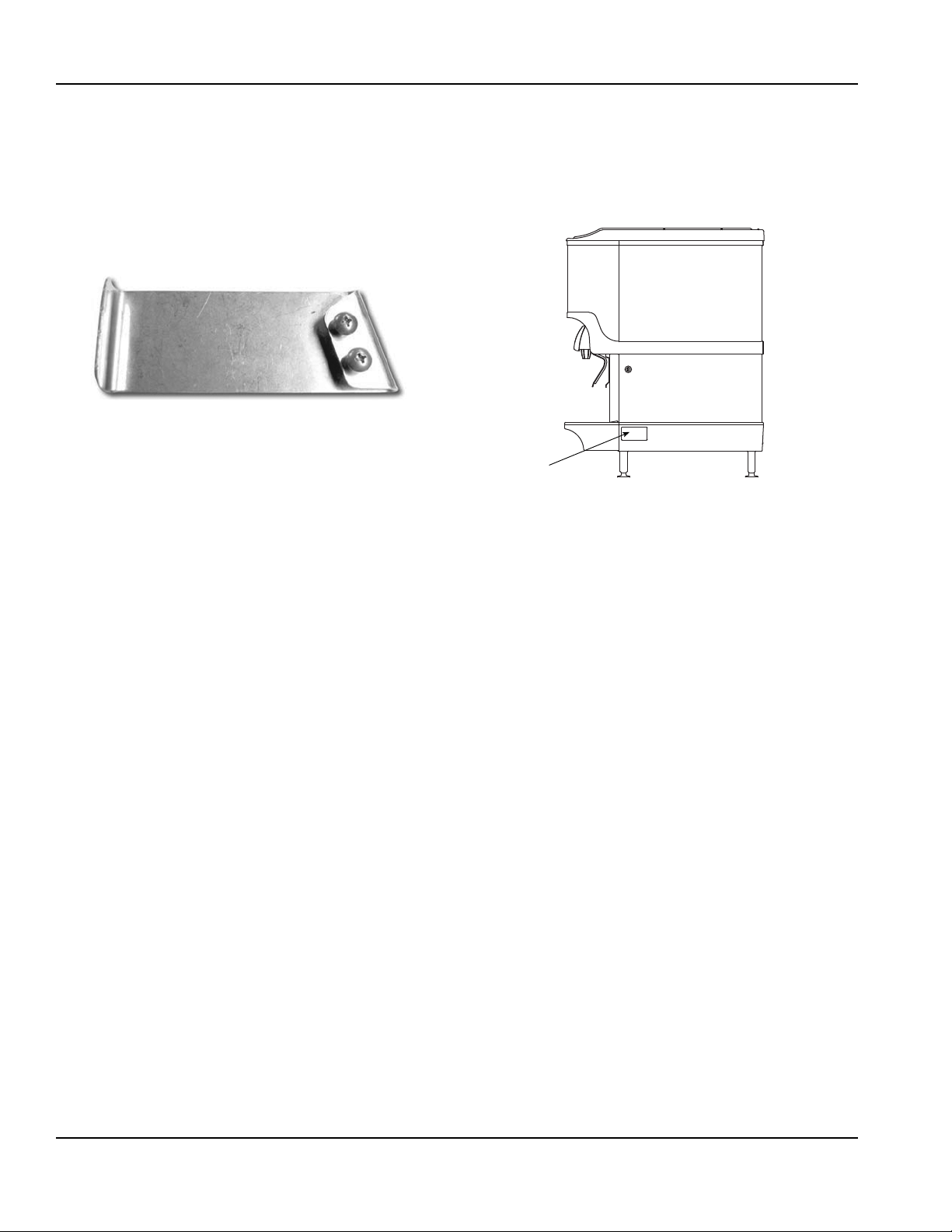
ICE FLOW RESTRICTOR
An optional ice flow restrictor decreases the amount of
ice allowed to enter the ice chute by blocking a small
area at the entrance of the dispenser chute . Th is in tur n
restricts the flow of ice that is dispensed into your cup.
Please refer to the instructions included in kit #5013822
for more information on how to install.
Ice Flow Restrictor
NOTE: For full information about icemaker installation,
including plumbing lines connections and electrical
requirements, see the icemaker installation manual.
LEGS
Legs are optional equipment with most MBE dispen sers.
Standard legs are four-inch (10.2 cm) tall stainless steel
legs. It is recommended if an icemaker is installed on top
of the dispenser, legs must not be installed. When
installing legs on a dispenser, leg braces must be used.
These are metal braces fitting side to side under the
dispenser that reinforce the leg attachment area.
Serial Number Location
This number is required when requesting information
from your local distributor. The serial number is listed on
the SERIAL NUMBER DECAL affixed to the dispenser.
Serial Number Location
Warranty Information
Consult your local MBE Distributor for terms and
conditions of your warranty. Your warranty specifically
excludes all beverage valve brixing, general
adjustments, cleaning, accessories and related
servicing.
Your warranty card must be returned to MBE to activate
the warranty on this equipment. If a warranty card is not
returned, the warranty period can begin when the
equipment leaves the MBE factory.
No equipment may be returned to MBE without a written
Return Materials Authorization (RMA). Equipment
returned without an RMA will be refused at MBE’s dock
and returned to the sender at the sender’s expense.
1-2
Please contact your local MBE distributor for return
procedures.
Part Number 020002115 10/11
Page 7
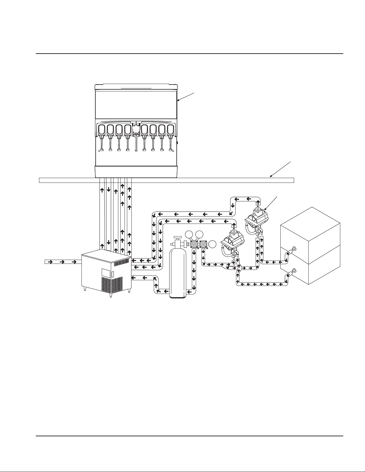
General System Overview
90
1800
60
Dispenser
BIB
Syrup Pump
Syrup
CO
2
Cylinder
Tap Water
Multiplex
Non-carbonated Water
Carbonated Water
Syrup
Syrup
Syrup
CO
2
CO
2
Carbonated Water
Syrup
Countertop
Syrup
B
a
g
-
I
n
-
B
o
x
S
y
r
u
p
C
a
r
t
o
n
CO
2
Section 2
Installation Instructions
Typical S Series Beverage Dispensing System
with Valves and Flex Manifolds
Part Number 020002115 10/11 2-1
Page 8
Installation Instructions Section 2
Pre-installation Checklist
When installing any system, first make sure the major components are available. Generally the major components
necessary for an installation are:
B-I-B SYSTEM ALSO:
B-I-B connectors
B-I-B regulator set
B-I-B rack
B-I-B syrup boxes
POST MIX SYSTEM:
regulator set
CO
2
Beverage dispenser
BULK SYRUP SYSTEM ALSO:
Syrup connectors for Bulk tank
Gas connectors for Bulk tank
Bulk syrup tanks
DOUBLE CHECK:
Do you have enough space to install the
dispenser or a dispenser and top mounted
cuber?
Does top mounted cuber (if utilized) have a
minimum of 6 inches (15.3 cm) clearance on all
sides?
Beverage tubing
tank
CO
2
Carbonator
Stepless (Oetiker) clamps
Chain for CO
tank
2
Is the countertop level?
Can the countertop support the weight of the
dispenser, or the dispenser/cuber combination
plus the weight of the stored ice?
ALSO CONSIDER:
Water line
Drain
Power outlet
Heating and air conditioning ducts
2-2
Part Number 020002115 10/11
Page 9
Section 2 Installation Instructions
ADDITIONAL CHECKS FOR TOP MOUNTED ICE MAKER INSTALLATIONS
Location — Avoid placing the dispenser and/or
ice machine near heat sources such as
radiators, ovens, refrigeration equipment and
direct sunlight.
Clearances — Six inch (15.2 cm) clearance on
all sides of the icemaker is needed.
Front of icemaker to be flush with front of
dispenser — The front of the icemaker mu st be
flush with the front of the dispenser. When the
icemaker is flush with the front of the dispenser,
some icemakers may overhang at the back of
the dispenser.
Drains — A separate drain line is required for
the ice machine, in addition to a drain line for
the ice/beverage dispenser.
Dispensers require an adapter kit to install
some top-mounted icemakers. Contact your
local distributor for the correct adapter kit.
Part Number 020002115 10/11 2-3
Page 10

Installation Instructions Section 2
I
E
F
G
H
D
B
A
C
C
D
E
B
A
Minimum Area
for Cutout
Dimensions
ABCDEFGH I
39.81"
(101.1 cm)
30.00"
(76.2 cm)
9.94"
(25.2 cm)
4.44"
(11.3 cm)
22.63"
(57.5 cm)
28.00"
(71.1 cm)
31.13"
(79.1 cm)
20.00"
(50.8 cm)
27.44"
(69.7 cm)
Footprint
ABCDE
30.00"
(76.20 cm)
2-4
31.13"
(79.07 cm)
19.81"
(50.32 cm)
4.00"
(10.16 cm)
24.00"
(61.00 cm)
Part Number 020002115 10/11
Page 11

Section 2 Installation Instructions
!
Warning
!
Warning
!
Warning
!
Warning
Location
Avoid placing the dispenser near heat sources such as
radiators, ovens, refrigeration equipment and direct
sunlight.
Carbon Dioxide (CO2) displaces oxygen. Exposure
to a high concentration of CO
which are followed rapidly by loss of consciousness
and suffocation. If a CO
particularly in a small area, immediately ventilate
the area before repairing the leak. CO
pumps should not be installed in an enclosed
space. An enclosed space can be a cooler or small
room or closet. This may include convenience
stores with glass door self serve coolers. If you
suspect CO
B-I-B pumps and / or CO
utilized.
may build up in an area, venting of the
2
gas causes tremors,
2
gas leak is suspected,
2
lines and
2
monitors should be
2
Grounding Instructions
Risk of electrical shock. Connect to a properly
grounded outlet only.
This appliance must be grounded. In the event of
malfunction or breakdown, grounding provides a path of
least resistance for electric current to reduce the risk of
electric shock. This appliance is equipped with a cord
having an equipment-grounding conductor and a
grounding plug. The plug must be plugged into an
appropriate outlet that is properly inst alled and grounded
in accordance with all local codes and ordinances.
Improper connection of the equipment-grounding
conductor can result in a risk of electric shock. The
conductor with insulation having an outer surface
that is green with or without yellow stripes is the
equipment grounding conductor. If repair or
replacement of the cord or plug is necessary, do not
connect the equipment-grounding conductor to a
live terminal. Check with a qualified electrician or
serviceman if the grounding instructions are not
completely understood, or if in doubt as to whether
the appliance is properly grounded. Do not modify
the plug provided with the appliance — if it will not fit
the outlet, have a proper outlet installed by a
qualified electrician.
When using electric appliances, basic precautions
should always be followed, including the following:
a. Read all the instructions before using the
appliance.
b. To reduce the risk of injury, close
supervision is necessary when an
appliance is used near children.
c. Do not contact moving parts.
d. Only use attachments recommended or
sold by the manufacturer.
e. Do not use outdoors.
f. For a cord-connected appliance, the
following shall be included:
• Do not unplug by pulling on cord. To
unplug, grasp the plug, not the cord.
• Unplug from outlet when not in use and
before servicing or cleaning.
• Do not operate any appliance with a
damaged cord or plug, or after the
appliance malfunctions or is dropped or
damaged in any manner. Contact the
nearest authorized service facility for
examination, repair, or electrical or
mechanical adjustment.
g. For a permanently connected appliance —
Turn the power switch to the off position
when the appliance is not in use and before
servicing or cleaning.
h. For an appliance with a replaceable lamp —
always unplug before replacing the lamp.
Replace the bulb with the same type.
i. For a grounded appliance — Connect to a
properly grounded outlet only. See
Grounding Instructions.
Part Number 020002115 10/11 2-5
Page 12

Installation Instructions Section 2
Backing Plate
to Be Inserted
Into Side
Pocket of
Bulkhead
Screws
Screws
New Ice Baffle
Backing Plate
to Be Inserted
Into Side
Pocket of
Bulkhead
Baffle, Manitowoc Ice Maker
Part #5007892
0.69"
(1.7 cm)
Ref.
6.32"
(16.0 cm)
Ref.
7.22"
(18.3 cm)
Ref.
Unit Installation
1. Place the dispenser in the desired location.
2. Run the beverage lines and water lines (make sure
to install the water connections to the proper inlets).
(Refer to plumbing diagrams)
3. Install drain plumbing and insulate.
(See Drainage Options)
4. Set flexible manifold for correct drink settings.
5. Fill bin with ice.
6. Connect power supply.
7. Brix beverage valves.
8. Meet all code requirements.
Installing Baffle for Ice Machine Installations
“S” SERIES BAFFLE
1. Remove both front panels.
2. Examine the ice machine to see if the machine has
four screws on the lower front plastic panels.
3. If there are screws, remove them from the
countersunk holes on the front surface of the
machine, save the screws.
4. Install the deflector, using the four screws removed
in step three.
5. Four screws and two backing plates are in the kit.
6. If there are no screws on the ice machine (step 2),
pierce the thin plastic countersunk holes, install the
backing plates and install the deflector using the
screws from the kit.
7. Replace the front panels.
“Q” SERIES BAFFLE
1. Position baffle on top of water well with tab on the
front and the other tab inside the water well.
2. Mount the baffle on the left side of the ice maker
using the hole and screw provided.
“S” Series Ice Machine
“Q” Series Ice Machine
2-6
Part Number 020002115 10/11
Page 13

Section 2 Installation Instructions
90° Elbow Fitting
Radiator Clamp
Flexible Tubing
Straight Fitting
Radiator Clamp
Flexible Tubing
Rear Access for Drain
Hose and Beverage Lines
Drainage Through Bottom
Drainage Through Back
Rear View
Water and Syrup Lines
CARBONATED WATER LINES
• Unit requires connection of two (2) carb water lines ,
(1/2" barb) one for each flex manifold and als o
completes the carbonated water syste m.
• Strip back the insulation on the conduit and route
through the hole in counter top. Directly connect the
lines to the left and right manifolds.
PLAIN WATER LINES
• Unit requires connection of two (2) plain water lines,
one for each flex manifold. 3/8" barb on end of check
valve (required for code). Use parts from installation
kit (2x2" black stripped 3/8" tube and 3/8" x 1/2" barb
adapter)
• Strip back the insulation on the conduit and route
through the hole in counter top. Directly connect the
lines to the left and right manifolds.
Drainage Options
SYRUP LINES
• The eight (8) valve unit has eight (8) syrup lines, Four (4)
for the left manifold and four (4) fo r the right manifold.
The ten (10) valve unit has ten (10) syrup lines, five (5)
on the left and five (5) on the right. All 3/8" barb fittings.
For 1/2" conduit syrup tubes (up to three (3)) use parts
from the installation kit. (3"x2" orange, green, white
stripped 3/8" tubes and 3/8" barb adapters) to connect 3/
8" barb to 1/2" syrup conduit tubes.
• Strip back the insulation on the conduit an d route through
the hole in counter top. Directly connect the lines to the
left and right manifolds.
• FULLY INSULATE (no air gaps) and finish with tape
wrap, all tubing from the flex manifolds to the conduit
bundle insulation. All tubing must be insulated and air
tight.
Part Number 020002115 10/11 2-7
Page 14

Installation Instructions Section 2
1234 5678
Left Flex
Manifold
Right Flex
Manifold
Manifold: Change to carbonated or non-carbonated water.
1. Rotate plunger 180° using a 5/32" Allen wrench.
2. Pull plunger out to get non-carbonated water.
3. Push plunger in to get carbonated water.
4. Turn plunger back 180° to lock.
Servend Recommended Plumbing
CW
C
CW
C
S1, S2, S3, S4 S5, S6, S7, S8
Plumbing Diagrams
S250M 8 VALVE
2-8
Part Number 020002115 10/11
Page 15

Section 2 Installation Instructions
Left Flex
Manifold
Right Flex
Manifold
Manifold: Change to carbonated or non-carbonated water.
1. Rotate plunger 180° using a 5/32" Allen wrench.
2. Pull plunger out to get non-carbonated water.
3. Push plunger in to get carbonated water.
4. Turn plunger back 180° to lock.
Servend Recommended Plumbing
CW
C
CW
C
S1, S2, S3, S4, S5
S6, S7, S8, S9, S10
S250M 10 VALVE
Part Number 020002115 10/11 2-9
Page 16

Installation Instructions Section 2
THIS PAGE INTENTIO NALLY LEFT BLANK
2-10
Part Number 020002115 10/11
Page 17

Component Identification
Merchandiser
Soda Valves
Key Switch
Carb/Non-Carb Water manifold
and Syrup/Soda Inlet
(Behind Splash Panel)
Drain Pan Grid
Drain Pan
Splash Panel
Counter
Section 3
Operation
Part Number 020002115 10/11 3-1
Page 18

Operation Section 3
RECOMMENDED ICE OTHER ICE SIZES AND SHAPES
Dice
7/8" x 7/8" x 7/8"
(2.2 x 2.2 x 2.2 cm)
Half Dice
3/8" x 1-1/8" x 7/8"
(1.0 x 2.9 x 2.2 cm)
Contour
3/8" x 1-1/4" x 1-1/4"
(1.0 x 3.2 x 3.2 cm)
Mini
7/8" Dia. x 3/4" Long
(2.2 cm Dia. x 1.9 cm Long)
Gourmet-Small
1" Dia. x 3/4"
(2.5 cm Dia. x 1.9 cm)
Crescent Cube
0.75"
(1.9 cm)
0.38"
(1.0 cm)
1.13"
(2.9 cm)
Sequence of Operation
ICE RECOMMENDED FOR DISPENSING
Dispensers are designed to dispense hard, cube ice up
to one-inch square. The ice shapes and sizes listed
above are recommended for dispensing. Warm “Super
Cooled” Ice Before Dispensing: “Super Cooled” ice is not
recommended for dispensing. “Super cooled” ice is ice
that has been stored in freezers below 32°F. Should it be
necessary to temporarily use “super cooled” ice, allow
the ice to warm at room temperature for 25 to 30
minutes before placing the ice in the dispenser.
ICE STORAGE AND DISPENSING
As the customer presses the rocking chute, the arm at
the top left rear of the chute pushes upward on the door
lock. The door opens until it contacts the stops in the
mounting brackets. The plastic arm on the ice ch ute also
activates the lever of the ice dispensing switch. When
activated, the micro switch starts the gear motor. The
gear motor turns the paddle wheel and agitator arm.
The paddle wheel carries ice. Periodic agitation is
standard on the 30" and larger dispensers. During
periodic agitation, the paddle wheel and agitator turn for
approximately three seconds every three and one halfhours. The door lock prevents ice from being dispensed
during the agitation cycle.
BEVERAGE VALVES
Post-mix beverage valves are designed to precisely
meter the flow of both water and syrup to obtain the
proper mixing ratio. The syrup and soda wate r
components of the post-mix beverage are mixed as they
leave the beverage valve.
ROCKING CHUTE ICE DISPENSING
As the customer presses the rocking chute, the arm at
the top left rear of the chute pushes upward on the door
lock. The door opens until it contacts the stops in the
mounting brackets. The plastic arm on the ice chute also
activates the lever of the ice dispensing switch. When
activated, the micro switch starts the gear motor. The
gear motor turns the paddle wheel and agitator bar.
CARBONATION
The purpose of the carbonator is to take regular tap
water at street water pressure (minimum 20 PSI,
maximum 80 PSI, dynamic or flowing pressure) 1/2"
water line and increase the water to beverage system
pressure (usually 100 PSI). This water is then combined
with the CO
same pressure, the CO
gas. Because the water and gas are at the
2
will dissolve into the water.
2
Chilling the mixture before dispensing will assist in
locking the carbon dioxide into the water. After
dispensing, the CO
The CO
will gradually leave the liquid due to pressure
2
may be unlocked from the liquid.
2
and temperature changes.
Components
The components of the carbonator are: water pump, an
electric motor to operate the pump, carbonator tank
where the water and CO
mix, and a water level control.
2
3-2
Part Number 020002115 10/11
Page 19

Section 3 Operation
1
RED
NO
2
3
6
4
5
COM NC
Operation
Carbon Dioxide (CO
) leaves the storage tank and
2
arrives at the carbonator tank through the gas inlet.
Water supply enters the carbonator pum p inlet at regular
street water line pressure (minimum 20 PSI, maximum
80 PSI, dynamic or flowing pressure). The water pump
increases the pressure of the water, which allows the
water to flow into the carbonator tank. The CO
and the
2
water mix together in the carbonator to produce the
carbonated water that is then sent to the soda dispenser.
The agitation of the water and CO
together in the tank
2
under high pressure creates the soda water. The quality
of carbonation (percent of CO
mixed in the water)
2
increases as the water temperature decreases and
exposure time increases.
The water level in the carbonator tank is controlled by a
water level control in the tank. This control turns the
pump motor off and on to maintain a preset level of liquid
in the tank. The water level control may be electronic
probes or a mechanical float.
SYRUP DELIVERY SYSTEM
Y our syrup location can va ry depending on the volume of
beverages served and ease of accessibility. Your
beverage system may set in a back storage room or
under the counter of the dispenser. Configurations are
almost limitless. Check the temperatures expected for
the storage location. Adverse temperatures can affect
the storage and quality of beverage products. It is
recommended the temperature of storage location
should not fall below 40°F or rise above 90°F.
RACKING
Regardless if you are working on a B-I-B or Figal
system, a place will be designated for placement of the
product. A rack (or shelf) system affords systematic
placement and complete usage of the beverage p aid for.
The B-I-B rack allows the boxes to lay properly for syrup
dispersal. Please check with your B-I-B syrup supplier.
Some boxes must be slightly tilted down, while others
may be in virtually any position. The Figal tank rack
keeps the newer and full tanks organized at one end of
the beverage line with the partial tanks at the othe r.
B-I-B
The Bag-In-Box system refers to a plastic disposab le
bag. The B-I-B normally contains 5 gallons of syrup,
however some locations offer 2-1/2 gallon B-I-B units.
This plastic bag is then held inside a cardboard or other
container. B-I-B systems are for post-mix applications
only .
PUMPS
The syrup in a B-I-B system is delivered to the beverage
system through gas operated pumps. These pumps
extract the syrup out of the bags, forcing th e sy r up
throughout the system.
AUTO BAG SELECTORS
These are used on higher volume B-I-B systems where
two or more bags of the same product are connected to
one pump and one system. An auto bag selector is
essentially a valve that automatically changes from one
bag (or series of bags) to another bag (or series of bags)
of syrup as the bags empty, allowing a constant flow of
product.
AGITATION TIMER
The timer is non-adjustable and is set to agitate the ice
for 3 seconds every 3.5 hours. Activating the dispenser
will reset the timer. After 3.5 hours of non-use, the timer
will energize the dispenser motor.
The LED tells the technician in which mode the timer is
operating. Rather than a jumper pin, this timer has a
female spade connector that must be connected to
terminal number 6.
When this jumper is in place, the LED will blink at
one-second intervals, this is the run mode.
When the jumper is open, the LED will flash every
0.4 second. This is the test mode and the timer will cycle
every 55 seconds in test mode. If the timer is left in test
mode, it will automatically reset to run mode.
Part Number 020002115 10/11 3-3
Page 20

Operation Section 3
Door Stops
Door Lock
Door
Ice
Delivery
Door Stops
Door
Door Lock
1/16”
to
1/4”
Tab
Switch Arm
Operation Checks & Adjustments
Rocking Chute Ice Delivery Switch Adjustment
To properly adjust the switch, first unplug the power cord
to the unit then remove the merchandiser. This will give
you access to the ice delivery switch located on the left
side of the rocking chute.
Begin by observing the chute by slowly pushing against
the rocking chute. When the ice delivery switch clicks,
measure the distance from the doo r stops on the rocking
chute bracket to the door. The distance between the two
must be no more than 1/4” (0.64 cm), but no less than
1/16” (0.16 cm).
The left side of the rocking chute has a tab that pushes
up on the ice delivery switch. To adjust it, use needle
nose pliers and bend the arm of the switch up or down in
order to change the point where the tab makes contact
with the switch arm.
3-4
Part Number 020002115 10/11
Page 21

Section 4
!
Caution
!
Warning
!
Warning
Maintenance
Cleaning
DAILY CLEANING
All cleaning must meet your local health department
regulations. The following cleaning instructions are
provided as a guide.
Use only warm soapy water to clean the exterior of
the tower. Do not use solvents or other cleaning
agents. Do not pour hot coffee into the drain pan.
Pouring hot coffee down the drain pan can
eventually crack the drain pan, especially if the
drain pan is cold or still contains ice.
Electric Shock Hazard
Unplug unit before servicing or cleaning.
When using cleaning fluids or chemicals, rubber
gloves and eye protection should be worn .
Clean the dispensing valves:
6. Remove nozzles and diffusers from beverage
valves.
Nozzle Removal
7. Rinse nozzle and diffuser with warm, clean water.
8. Clean nozzles and diffusers with soapy water and a
soft bristle brush.
9. Clean the underside of the beverage valves with
warm, soapy water. Rinse with clean damp towel.
10. Replace nozzles and diffusers on valves.
11. Turn on the key switch.
Clean the exterior and drain pan:
1. Turn off the key switch located on either right or left
side of the unit.
2. Lift the grid and remove it from the drain pan.
3. Using mild soap, warm water and a clean cloth, wipe
the drain pan and splash panel. Then, rinse with
clean, warm water. Allow plenty of warm (not hot)
water to run down the drain of the drain pan, to
remove syrup residue that can clog the drain
opening.
4. Wash the grid, then rinse with clean water. Place the
grid back in the drain pan.
5. Wash all exterior surfaces of the unit with warm
water and a clean cloth. Wipe again with a clean, dry
cloth.
Part Number 020002115 10/11 4-1
Page 22

Maintenance Section 4
!
Caution
!
Warning
MONTHLY CLEANING
Unplug unit before servicing or cleaning ice bin.
Ice bin contains part s tha t can move at any time and
will cause injury if hands are in the way.
When using cleaning fluids or chemicals, rubber
gloves and eye protection must be worn .
Clean and sanitize the ice bin:
1. Unplug unit and remove all ice from the ice bin.
2. Mix a solution of mild detergent to clean the
dispenser bin and components.
3. Wash the ice bin using a sponge and the mild
detergent solution.
4. Using the mild detergent solution and a soft bristle
brush or clean cloth, clean the following dispenser
parts:
• Entire bin
• Paddle wheel
• Paddle wheel area
•Agitator
• Paddle wheel pin
• Ice Chute
5. Rinse all the parts in clean, running water.
6. Prepare 2 gallons of sanitizing solution by mixing
1/2 ounce of household bleach (that contains 5.25 %
sodium hypochlorite) with 2 gallons of 120°F water.
The mixture should not exceed 100 PPM of chlorine.
Or mix a solution of any approved sanitizer,
following the directions for mixing and applying the
sanitizer.
7. Sanitize the ice bin and cold plate with the sanitizing
solution for at least 10 seconds.
8. Allow to air dry. Do not rinse.
Re-assembling the dispenser parts:
9. Re-assemble parts in the following order:
• Bin liner
• Paddle wheel
•Agitator
• Paddle wheel pin
• Ice chute
• Merchandiser
10. Hand tighten all knurled fasteners.
11. Pour in fresh, sanitary ice and replace the plastic lid
on the top of the dispenser.
12. Plug in the unit’s electrical cord.
13. Check for proper ice dispensing.
• Rear bushing
• Motor shaft
• Strip lids (where applicable)
4-2
Part Number 020002115 10/11
Page 23

Section 4 Maintenance
C
D
E
F
G
A
B
Disassembly
DISASSEMBLY FOR CLEANING & MAINTENANCE
NOTE: Sanitize the ice dispenser at Initial Start-u p in
addition to monthly sanitizing. Y ou will need a slotted
screwdriver in order to disassemble.
Disassemble parts in the following order:
A. Merchandiser
B. Ice chute
C. Paddle wheel or agitator pins
D. Agitator
E. Paddle wheel
F. Bin liner
G. Paddle wheel area
Accessing a Dispenser Bin Top Mounted with a Manitowoc
Ice Machine:
1. Remove the front panel of the ice machine.
2. Remove the ice deflection baffle. This will give you
access to the dispenser bin.
3. If the Manitowoc ice maker is operating, wait for the
sheet of ice to fall into the dispenser bin.
When the ice sheet falls into the dispenser bin, immediately
place toggle switch of the ice machine to the OFF position. If
the Manitowoc ice maker is NOT operating, place the toggle
switch of the ice machine to the OFF position.
4. On models without a top mounted ice maker, remove
the plastic lid from the top of the dispenser .
5. Remove all ice from the dispenser.
6. Disconnect electrical power to the dispenser.
7. Remove agitator arm and paddle wheel pin.
a. With agitator arm in any position remove hitch clip
pin from the mushroom bushing on the rear of the
ice bin.
b. Push the agitator bar toward the bush ing to remove
it from the paddle wheel hub.
NOTE: If a top mount ice maker is installed, sliding the ice
maker to one side will make bin component removal easier.
If the ice maker is hard plumbed it will need to be
disconnected.
8. Remove paddle wheel, bin liner and paddle wheel area.
9. Move the front of the agitator to one side and slide the
agitator forward until the rear of the agitator shaft is clear
of the bushing.
10. Remove the agitator from the bin area.
1 1. Slide the paddle wheel from its shaf t.
12. Loosen the four knurled fasteners that hold the bin liner
in place.
13. Remove the bin liner .
14. Remove the paddle wheel area from the bi n.
15. Discard the remaining ice in the bin.
Beverage/Ice Dispenser
Part Number 020002115 10/11 4-3
Page 24

Maintenance Section 4
REMOVAL OF GEAR MOTOR
These instructions are provided as a guide for the
removal of the gear motor. Depending on the model
number of your dispenser, these instructions may vary
slightly.
1. Unplug the dispenser.
2. Unplug the motor.
3. Remove motor mount pins.
4. Slide motor towards you.
5. Notice alignment of the chamfered edge of drive
shaft.
6. New motor must have the same alignment (within
15 degrees).
7. To get correct alignment you can do one of two
things:
a. Turn drive shaft with an adjustable wrench,
being careful not to damage the drive shaft.
b. Plug in the unit, plug in the motor and use the
ice dispense switch to move the drive shaft into
correct alignment.
8. If you plugged in the unit to help with alignment of
drive shaft now unplug the unit.
9. Slide motor up into housing, making sure that the
tabs fit on the bracket.
10. Install motor mount pins.
11. Plug in motor.
12. Test unit.
4-4
Part Number 020002115 10/11
Page 25

Section 4 Maintenance
!
Warning
!
Warning
Bag
side
connector
Sanitizing
BEVERAGE SYSTEM CLEANING
Flush sanitizing solution from syrup system.
Residual sanitizing solution left in system could
create a health hazard.
When using cleaning fluids or chemicals, rubber
gloves and eye protection must be wor n.
Sanitize the beverage system at initial start-up as well as
regularly scheduled cleaning. The drain pan must be in
place under soda valves, to carry away detergent and
sanitizing agents that will be flushed through valves.
BAG-IN-BOX SYSTEM SANITATION
The procedure below is for the sanitation of one
syrup circuit at a time. Repeat to sanitize additional
circuits.
You will need the following items to clean and sanitize
the Bag-in-Box (BIB) beverage system:
• Three (3) clean buckets
2. Disconnect the “syrup-line side” of the bag-in-box
connector.
3. Rinse connector with warm tap water.
4. Connect syrup connector to BIB connector and
immerse both into Bucket 1. A “bag-side” connector
can be created by cutting the connector from an
empty disposable syrup bag.
• Plastic brush or soft cloth
• Mild detergent
• Unscented bleach (5% Na CL O) or
Commercial sanitizer
• Bag-In-Box bag connector
1. Prepare the following in the buckets:
• Bucket 1 — warm to hot tap water for rinsing.
• Bucket 2 — mild detergent and warm to hot
water.
• Bucket 3 — mix a solution of unscented bleach
(5% Na CL O) or commercial sanitizer and warm
to hot water. Mi xture should supply 100 PPM
available chlorine (1/4 oz. bleach to 1 gallon
water).
Part Number 020002115 10/11 4-5
Page 26

Maintenance Section 4
!
Caution
5. Draw rinse water through system until clean water is
dispensed. Most beverage valves allow the syrup
side to be manually activated by depressing the
syrup pallet.
6. Connect Bucket 2 to system.
7. Draw detergent solution through system until
solution is dispensed.
8. Repeat steps 2-7 until all syrup circuits contain
detergent solution.
9. Allow detergent solution to remain in the system for
5 minutes.
10. Connect Bucket 3 to system.
11. Draw sanitizing solution through system until
solution is dispensed.
12. Repeat step 11 until all syrup circuits contain
sanitizer solution.
13. Allow sanitizer solution to remain in system for 15
minutes.
14. Remove nozzles and diffusers from beverage
valves.
15. Scrub nozzles, diffusers and all removable valve
parts (except electrical parts) with a plastic brush or
a soft cloth and the detergent solution.
16. Soak nozzles, diffusers and removable valve parts
(except electrical parts) in sanitizer for 15 minutes.
17. Replace nozzles, diffusers and valve parts.
18. Connect Bucket 1 to system.
19. Draw rinse water through system until no presence
of sanitizer is detected.
20. Attach syrup connectors to BIB’s.
Preventive Maintenance
Preventative maintenance is a vital part of keeping your
dispenser in top condition. Following the guidelines
below will assist you in continued trouble-free operation
of your unit.
1. Conduct daily maintenance of the machine.
2. Perform monthly maintenance of the machine.
3. Perform periodic maintenance and sanitizing of
beverage system.
4. Do not overfill the dispenser bin with ice.
5. Do not allow the dispenser to sit for prolonged
periods of non use with ice in the bin.
6. Most ice dispenser service problems are caused by
low usage of the ice dispenser.
7. Do not allow ice to remain in the bin more than a day
in order to prevent ice from freezing together and/or
stagnant ice.
Possible excess ice storage reasons:
• Storage capacity exceeds daily requirements.
• Low demand during the off season.
• Dispenser oversized with future growth in mind.
Lower ice storage to meet one day’s needs. If you
manually fill ice, fill only with the appropriate amount of
ice. Fill the dispenser with fresh ice each morning. Do
not fill the dispenser at night just before shut down. Ice
cubes can freeze together if not dispensed.
Contact MBE at 1-800-367-4233 for more information
about our ProActive Maintenance Program.
Shipping, Storage and Relocation
21. Draw syrup through system until only syrup is
dispensed.
22. Discard first 2 drinks.
4-6
Before shipping, storing, or relocating this unit,
syrup systems must be sanitized. After sanitizing, all
liquids (sanitizing solution and water) must be
purged from the unit. A freezing environment
causes residual sanitizing solution or water
remaining inside the unit to freeze, resulting in
damage to internal components.
Part Number 020002115 10/11
Page 27

Section 5
Before Calling for Service
Checklist
If a problem arises during operation of your dispenser, follow the checklist below before calling service. Routine
adjustments and maintenance procedures are not covered by the warranty.
Problem Possible Cause To Correct
Dispenser will not dispense ice (and NO
SOUNDS are heard when machine is
activated).
Dispenser will not dispense ice (motor
runs but no ice movement is heard in
bin).
Excessive clustering or bridging of ice. Loaded ice not broken up. (Caution:
Ice dispenses continuously. Misaligned microswitch. Adjust microswitch.
Thumping noise or irregular sound at a
particular area of the dispenser.
Dispensing crushed ice or reduced
dispensing speed.
Door will not close. Ice jammed in chute. Adjust bridge in ice maker or, when
Mounting brackets for rocking chute have
spread too far apart.
No power. Check electrical connection.
Loose wire in electrical system. Thoroughly check all wire connections.
Dispenser overloaded with ice. Remove ice from dispenser until unit will
operate.
Motor not working. Check thermally protected motor.
Replace motor or capacitor if necessary.
No ice in bin. Fill dispenser with ice.
Door not opening. Check rocking chute mechanism or
electric solenoid operation.
Paddle wheel pin slipped from the paddle
wheel.
Super cooled ice is not covered by the
Servend warranty.)
Excessive water spilling from the ice
maker.
Poorly adjusted ice maker. Adjust ice maker to eliminate large waffle
Extremely low usage of the dispenser. Lower the ice level in the bin.
Agitation timer set incorrectly. Test agitation timer.
Shaved ice clusters in the bitn. Remove clusters, discover why ice is
Water spillage from ice machine into
dispenser bin.
Agitation timer. Test agitation timer.
Bridge of ice sheet is too thick. Adjust ice maker.
Paddle wheel area broken or cracked. Replace paddle wheel area.
Ice clusters in bin. Break up or remove clusters.
Door not fully open. Adjust door.
Door and/or door lock has come out of
place.
Replace paddle wheel pin.
Break ice clusters before manually filling
the dispenser. (See ice
recommendations.)
Adjust ice maker to eliminate water
spillage.
shapes.
shaving, and then repair.
Adjust ice maker.
manually filling, break up clusters.
Replace door and lock into proper
position.
Bend parts into shape.
Part Number 020002115 10/11 5-1
Page 28

Before Calling for Service Section 5
THIS PAGE INTENTIO NALLY LEFT BLANK
5-2
Part Number 020002115 10/11
Page 29

Page 30

© 2011 Manitowoc
Continuing product improvements
may necessitate change of
specifications without notice.
Part Number 020002115 10/11
Manitowoc Beverage Systems
Sellersburg, IN 47172, USA
Ph: 812-246-7000 Fax: 812-246-7024
Visit us online at: www.manitowocfsg.com
2100 Future Drive
 Loading...