

Page 1
Operating instructions: Rx 12 DS receiver
35 MHz band A Order No. 5 5936
35 MHz band B (36 MHz*) Order No. 5 5938
40 MHz (41 MHz) Order No. 5 5937
The Rx 12 DS receiver has been developed specifically for
the new PPM 12 transmission process, which is used for
the first time in the PROFI mc 4000. This technology is
able to transmit a maximum of 12 channels. All twelve
channels operate at equal high speed, without any delay,
and all twelve can be used without restriction for any model
function.
The jumper (black bridging plug) fitted to socket 12
switches the receiver to 9-channel operation for
compatibility with earlier transmitters. This is the mode in
which the receiver is supplied as standard.
Up to three batteries can be connected to the Rx 12 DS.
This innovation makes for great versatility, and allows the
user to select the optimum power supply arrangement for
receiver and servos. The possible options are described in
detail in Section 2.
1. PPM 9 and PPM 12
transmission modes
Important: the Rx 12 DS receiver can process either PPM 9
or PPM 12 si gnals. If you set a transmission mode on the
transmitter which does not match the receiver, the receiver
will not work at all. If the receiver picks up a PCM signal, an
unusable signal (same channel interference) or a signal
which is too weak to be usable, it switches the servo outputs off.
Advantage: if you land "out" and have to recover your
model with the transmitter switched off, the servos stay at
rest, i.e. they will not move uncontrollably and cause damage to themselves or the model's linkages.
Default setting: PPM 9
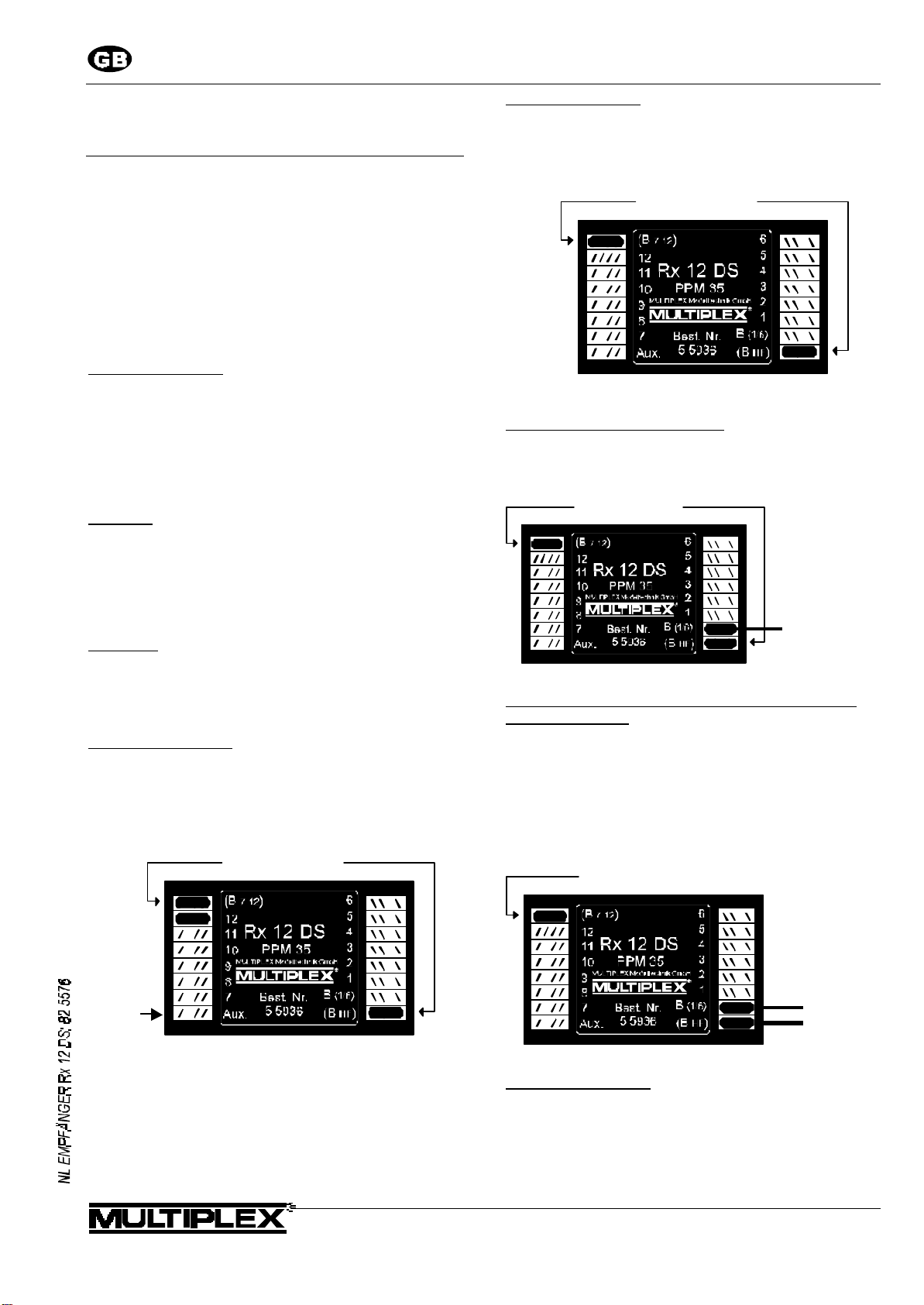
The receiver is supplied with a jumper fitted to socket 12,
i.e. it is in PPM 9 transmission mode. In this mode the
"superfluous" sockets 10 and 11 are wired in parallel to
sockets 1 and 2, and can therefore be used to replace two
Y-leads.
Power supply
jump ers
Switching to PPM 12
To use 12-channel mode you must remove the jumper
fitted to socket 12. Sockets 10 to 12 can then be used directly for servos 10 to 12. Be sure to keep the spare jumper
in a safe place!
Power su pply
ju mpers
cha nnel 1 2
cha nnel 1 1
cha nnel 1 0
2. Alternative battery circuits
Default mode: one shared battery
If you want to use a single battery, leave the jumpers in the
sockets marked B(7-12) and B(HF). Connect the battery (or
switch harness) to the socket marked B(1-6).
Power supply
jumpers
Comm on battery
Two separate batteries for servos and RF section (receiver electronics)
In this mode a separate battery is used for the RF section
(receiver electronics). A small battery (e.g. 270 mAh or 500
mAh) is adequate, as the consumption of the electronics is
only about 35 mA.
The advantage of this arrangement is that possible interference produced by the servos cannot reach the receiver
via the battery.
Power suppl y
jump er
for PPM9
= cha nnel 1
= cha nnel 2
unused
Three battery mode
(see next page)
modelltechnik gmbh • Neuer Weg 15 • D-75223 Niefern
Battery fo r:
servos 1-12
RF sectio n
Page 2
Operating instructions: Rx 12 DS receiver
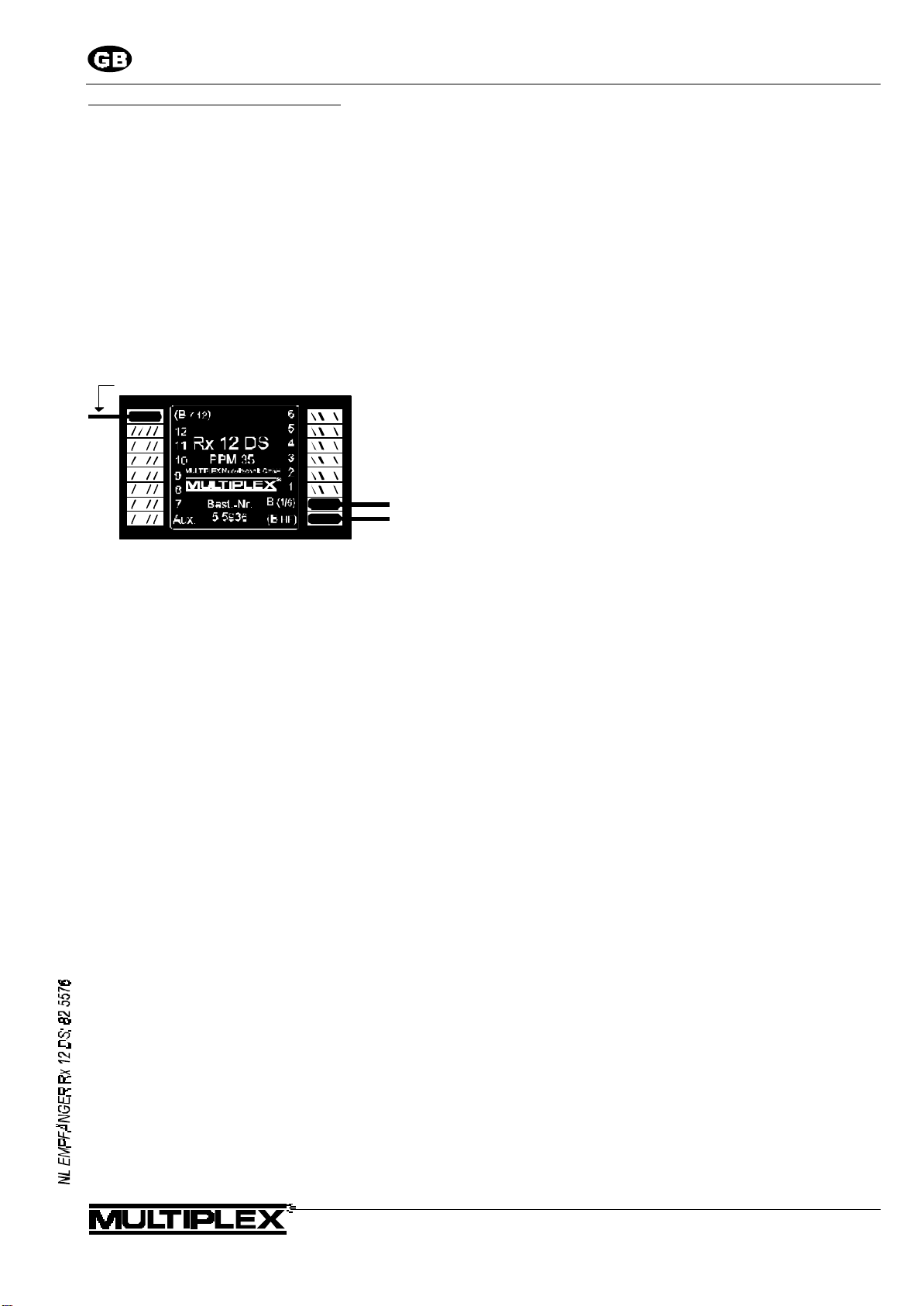
Using the receiver with three batteries
In this mode a separate battery is used for each of the
following
• the RF section (receiver electronics),
• servos 1 to 6, and
• servos 7 to 12
A divided power supply offers three advantages:
• if your model carries a large number of servos, the
current load on each battery is reduced.
• "emergency operation" is possible if one battery fails:
vital control functions are "doubled up" and the servos
shared by the two batteries
• the two servo groups can be operated with different
numbers of cells if you are using servos of suitable
specification.
Batter y for servos 7 - 12
Batter y for :
ser vos 1 - 12
RF secti on
modelltechnik gmbh • Neuer Weg 15 • D-75223 Niefern
 Loading...