

Page 1
# 26 4273
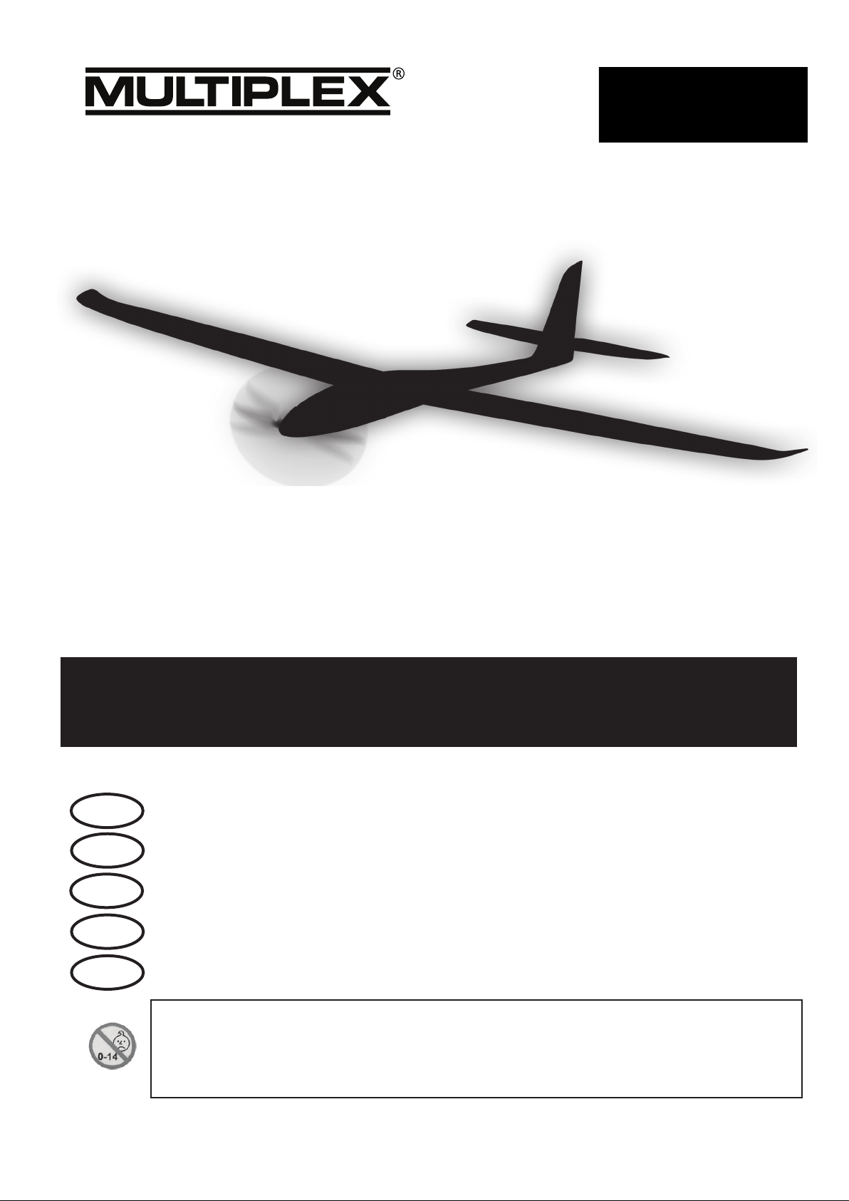
FunGlider
D
GB
F
I
ES
Anleitung 2 ... 9
Instructions 10 ... 17
Instructions 18 ... 29
Istruzione 30 ... 37
Instrucciones 38 ... 45
Abbildungen
Illustrations
Illustrations
Ilunstrazioni
Ilustraciónes
© Copyright by MULTIPLEX 2015 Version 1.0
23 ... 26
Ersatzteile
Replacement parts
Pièces de rechanges
Parti di ricambio
Repuestos
46 ... 47
Page 2

Sicherheitshinweise für MULTIPLEX-Flugmodelle
Das Modell ist KEIN SPIELZEUG im üblichen Sinne.
Mit Inbetriebnahme des Modells erklärt der Betreiber, dass er den Inhalt der Betriebsanleitung, besonders zu Sicher-
heitshinweisen, Wartungsarbeiten, Betriebsbeschränkungen und Mängel kennt und inhaltlich nachvollziehen kann.
Dieses Modell darf nicht von Kindern unter 14 Jahren betrieben werden. Betreiben Minderjährige das Modell unter der
Aufsicht eines, im Sinne des Gesetzes, fürsorgepichtigen und sachkundigen Erwachsenen, ist dieser für die Umsetzung
der Hinweise der BETRIEBSANLEITUNG verantwortlich.
DAS MODELL UND DAZUGEHÖRIGES ZUBEHÖR MUSS VON KINDERN UNTER 3 JAHREN FERNGEHALTEN
WERDEN! ABNEHMBARE KLEINTEILE DES MODELLS KÖNNEN VON KINDERN UNTER 3 JAHREN VERSCHLUCKT
WERDEN. ERSTICKUNGSGEFAHR!
Beim Betrieb des Modells müssen alle Warnhinweise der BETRIEBSANLEITUNG beachtet werden. Die Multiplex Mo-
dellsport GmbH & Co. KG ist nicht haftungspichtig für Verluste und Beschädigungen jeder Art, die als Folge falschen
Betriebes oder Missbrauches dieses Produktes, einschließlich der dazu benötigten Zubehörteile entstehen. Dies beinhaltet
direkte, indirekte, beabsichtigte und unabsichtliche Verluste und Beschädigungen und jede Form von Folgeschäden.
Jeder Sicherheitshinweis dieser Anleitung muss unbedingt befolgt werden und trägt unmittelbar zum sicheren Betrieb
Ihres Modells bei. Benutzen Sie Ihr Modell mit Verstand und Vorsicht, und es wird Ihnen und Ihren Zuschauern viel
Spaß bereiten, ohne eine Gefahr darzustellen. Wenn Sie Ihr Modell nicht verantwortungsbewusst betreiben, kann dies
zu erheblichen Sachbeschädigungen und schwerwiegenden Verletzungen führen. Sie alleine sind dafür verantwortlich,
dass die Betriebsanleitungen befolgt und die Sicherheitshinweise in die Tat umgesetzt werden.
D
Bestimmungsgemäße Verwendung
Das Modell darf ausschließlich im Hobbybereich verwendet werden. Jede weitere Verwendung darüber hinaus ist nicht
erlaubt. Für Schäden oder Verletzungen an Menschen und Tieren aller Art haftet ausschließlich der Betreiber des Modells
und nicht der Hersteller.
Zum Betrieb des Modells darf nur das von uns empfohlene Zubehör verwendet werden. Die empfohlenen Komponenten
sind erprobt und auf eine sichere Funktion passend zum Modell abgestimmt. Werden andere Komponenten verwendet
oder das Modell verändert, erlöschen alle Ansprüche an den Hersteller bzw. den Vertreiber.
Um das Risiko beim Betrieb des Modells möglichst gering zu halten, beachten Sie folgende Punkte:
Das Modell wird über eine Funkfernsteuerung gelenkt. Keine Funkfernsteuerung ist sicher vor Funkstörungen.
Solche Störungen können dazu führen, dass Sie zeitweise die Kontrolle über Ihr Modell verlieren. Deshalb müssen Sie beim Betrieb Ihres Modells zur Vermeidung von Kollisionen immer auf große Sicherheitsräume in allen
Richtungen achten. Schon beim kleinsten Anzeichen von Funkstörungen müssen Sie den Betrieb Ihres Modells
einstellen!
Sie dürfen Ihr Modell erst in Betrieb nehmen, nachdem Sie einen kompletten Funktionstest und einen Reichwei-
tentest, gemäß der Anleitung Ihrer Fernsteuerung, erfolgreich ausgeführt haben.
Das Modell darf nur bei guten Sichtverhältnissen geogen werden. Fliegen Sie nicht in Richtung Sonne, um nicht
geblendet zu werden, oder bei anderen schwierigen Lichtverhältnissen.
Ein Modell darf nicht unter Alkoholeinuss oder Einuss von anderen Rauschmitteln oder Medikamenten betrie-
ben werden, die das Wahrnehmungs- und Reaktionsvermögen beeinträchtigen.
Fliegen Sie nur bei Wind- und Wetterverhältnissen, bei denen Sie das Modell sicher beherrschen können. Be-
rücksichtigen Sie auch bei schwachem Wind, dass sich Wirbel an Objekten bilden, die auf das Modell Einuss
nehmen können.
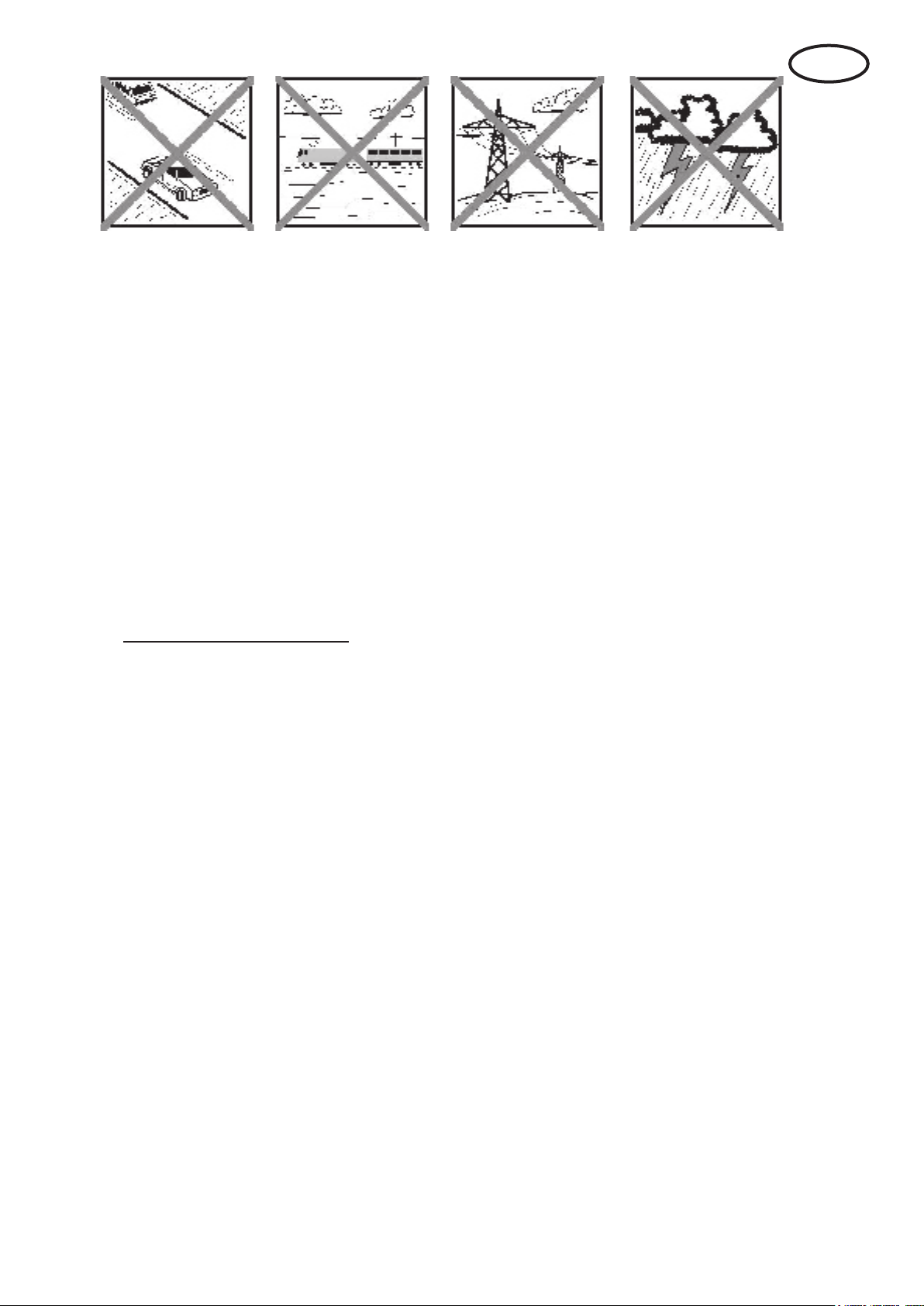
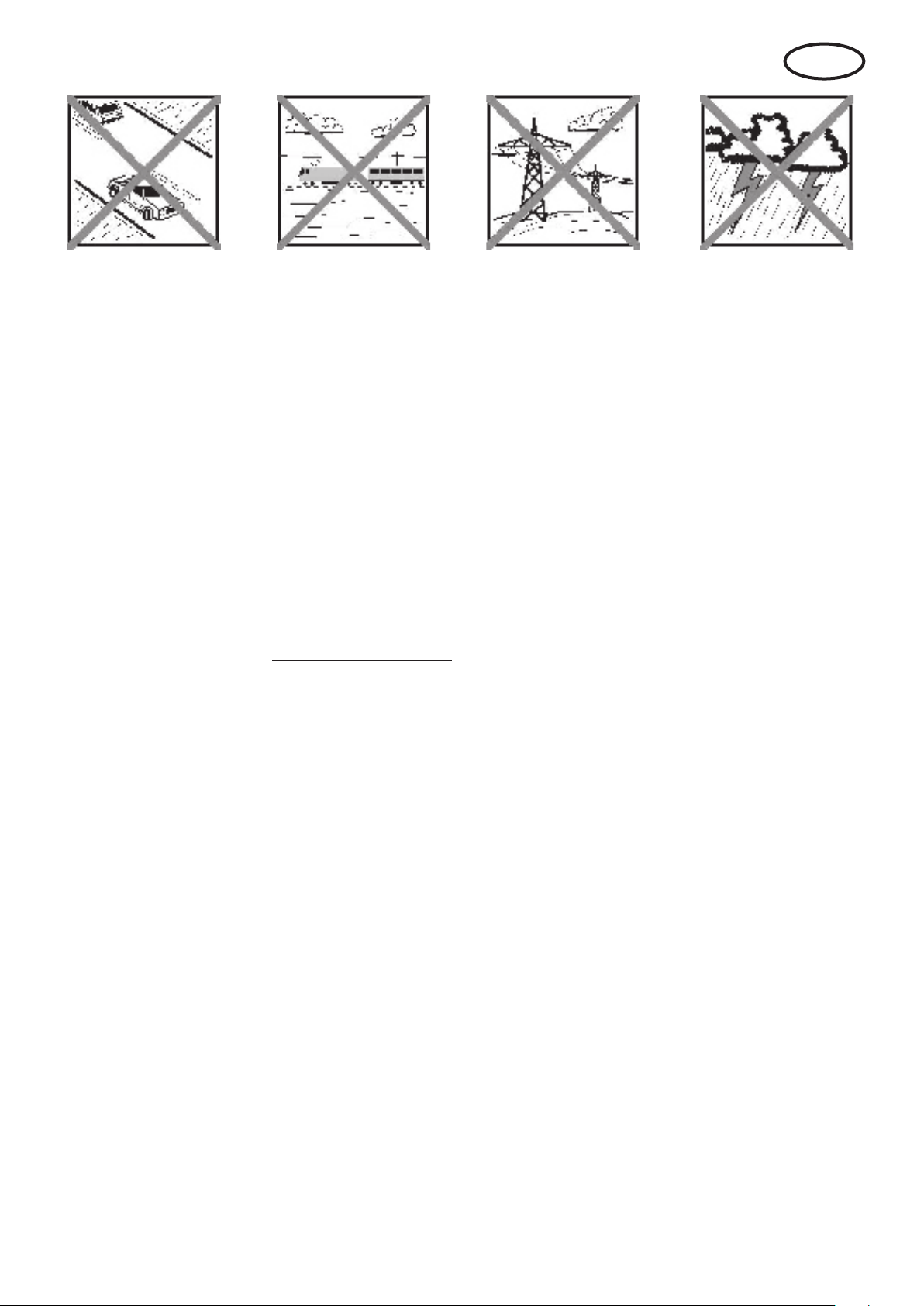
Fliegen Sie nie an Orten, an denen Sie andere oder sich selbst gefährden können, wie z.B. Wohngebiete, Über-
landleitungen, Straßen und Bahngleise.
Niemals auf Personen und Tiere zuiegen. Anderen Leuten dicht über die Köpfe zu iegen ist kein Zeichen für
wirkliches Können, sondern setzt andere Leute nur ein unnötiges Risiko aus. Weisen Sie auch andere Piloten
in unser aller Interesse auf diese Tatsache hin. Fliegen Sie immer so, dass weder Sie noch andere in Gefahr
kommen. Denken Sie immer daran, dass auch die allerbeste Fernsteuerung jederzeit gestört werden kann. Auch
langjährige, unfallfreie Flugpraxis ist keine Garantie für die nächste Flugminute.
2
Page 3
D
Restrisiken
Auch wenn das Modell vorschriftsmäßig und unter Beachtung aller Sicherheitsaspekten betrieben wird, besteht immer
ein gewisses Restrisiko.
Eine Haftpichtversicherung ist daher obligatorisch. Falls Sie in einen Verein oder V erband eintreten, können Sie diese
Versicherung dort abschließen. Achten Sie auf ausreichenden Versicherungsschutz (Modellugzeug mit Antrieb). Halten
Sie Modelle und Fernsteuerung immer absolut in Ordnung.
Folgende Gefahren können im Zusammenhang mit der Bauweise und Ausführung des Modells auftreten:
Verletzungen durch die Luftschraube: Sobald der Akku angeschlossen ist, ist der Bereich um die Luftschraube
freizuhalten. Beachten Sie auch, dass Gegenstände vor der Luftschraube angesaugt werden können oder Gegenstände dahinter weggeblasen werden können. Das Modell kann sich in Bewegung setzen. Richten Sie es
daher immer so aus, dass es sich im Falle eines ungewollten Anlaufen des Motors nicht in Richtung anderer
Personen bewegen kann. Bei Einstellarbeiten, bei denen der Motor läuft oder anlaufen kann, muss das Modell
stets von einem Helfer sicher festgehalten werden.
Absturz durch Steuerfehler: Kann dem besten Piloten passieren, deshalb nur in sicherer Umgebung iegen; ein
zugelassenes Modelluggelände und eine entsprechende Versicherung sind unabdingbar.
Absturz durch technisches Versagen oder unentdeckten Transport- oder V orschaden. Die sorgfältige Überprüfung
des Modells vor jedem Flug ist ein Muss. Es muss jedoch immer damit gerechnet werden, dass es zu Material-
versagen kommen kann. Niemals an Orten iegen, an denen man Anderen Schaden zufügen kann.
Betriebsgrenzen einhalten. Übermäßig hartes Fliegen schwächt die Struktur und kann entweder zu plötzlichem
Materialversagen führen, oder bei späteren Flügen das Modell aufgrund von „schleichenden“ Folgeschäden
abstürzen lassen.
Feuergefahr durch Fehlfunktion der Elektronik. Akkus sicher aufbewahren, Sicherheitshinweise der Elektronik-
komponenten im Modell, des Akkus und des Ladegerätes beachten, Elektronik vor Wasser schützen. Auf ausreichende Kühlung bei Regler und Akku achten.
Die Anleitungen unserer Produkte dürfen nicht ohne ausdrückliche Erlaubnis der Multiplex Modellsport GmbH
& Co. KG (in schriftlicher Form) - auch nicht auszugsweise in Print- oder elektronischen Medien reproduziert
und / oder veröffentlicht werden.
3
Page 4
RR FunGlider # 26 4273
Machen Sie sich mit dem Bausatz vertraut!
MUL TIPLEX - Modellbaukästen unterliegen während der Produktion einer ständigen Materialkontrolle. Wir hoffen, dass
Sie mit dem Baukasteninhalt zufrieden sind. Wir bitten Sie jedoch, alle Teile (nach Stückliste) vor V erwendung zu prüfen,
da bearbeitete Teile vom Umtausch ausgeschlossen sind. Sollte ein Bauteil einmal nicht in Ordnung sein, sind wir nach
Überprüfung gern zur Nachbesserung oder zum Umtausch bereit. Senden Sie das Teil, bitte ausreichend frankiert, an
unseren Service ein und fügen Sie unbedingt die vollständig ausgefüllte Reklamationsmeldung (Formular) bei. Wir arbeiten ständig an der technischen Weiterentwicklung unserer Modelle. Änderungen des Baukasteninhalts in Form, Maß,
Technik, Material und Ausstattung behalten wir uns jederzeit und ohne Ankündigung vor. Bitte haben Sie Verständnis
dafür, dass aus Angaben und Abbildungen dieser Anleitung keine Ansprüche abgeleitet werden können.
Achtung!
Ferngesteuerte Modelle, insbesondere Flugmodelle, sind kein Spielzeug im üblichen Sinne. Ihr Bau und Betrieb
erfordert technisches Verständnis, ein Mindestmaß an handwerklicher Sorgfalt sowie Disziplin und Sicherheitsbewusstsein.
Fehler und Nachlässigkeiten beim Bau und Betrieb können Personen- und Sachschäden zur Folge haben. Da der
Hersteller keinen Einuß auf ordnungsgemäßen Zusammenbau, Wartung und Betrieb hat, weisen wir ausdrücklich auf
diese Gefahren hin.
Wichtiger Hinweis
Das Modell hat, wie jedes Flugzeug, statische Grenzen! Sturzüge und unsinnige Manöver im Unverstand können zum
Verlust des Modells führen. Beachten Sie: In solchen Fällen gibt es von uns keinen Ersatz. T asten Sie sich also vorsichtig
an die Grenzen heran. Das Modell ist auf den von uns empfohlenen Antrieb ausgelegt, kann aber nur einwandfrei gebaut
und unbeschädigt den Belastungen standhalten. Weitere Tuningmaßnahmen setzen Sachverstand und entsprechend
sinnvolle Maßnahmen zur weiteren Verstärkung voraus.
D
Das Modell ist nahezu ugfertig vormontiert. Das Modell ist somit in kürzester Zeit betriebsbereit. Lesen Sie vor Fertigstellung und Inbetriebnahme die Anleitung und beachten unbedingt auch die Sicherheitshinweise und Tipps.
Um das Modell vollständig auszurüsten, ist noch ein Empfänger und der Antriebsakku notwendig. Unsere Empfehlungen
hierzu entnehmen Sie bitte aus der Anleitung und darüber hinaus (z.B. Sender, Ladegerät etc.) dem aktuellen Katalog
oder der Multiplex Homepage unter: www.multiplex-rc.de
Stückliste RR
Lfd. Stk. Bezeichnung Material Abmessungen
1 1 Bauanleitung
3 * 1 Rumpf vormontiert * Elapor geschäumt Fertigteil
5 * 1 Tragäche links * Elapor geschäumt Fertigteil
6 * 1 Tragäche rechts * Elapor geschäumt Fertigteil
7+8 1 Höhenleitwerk Elapor geschäumt Fertigteil
30 50 Trimmgewicht Metallkugel Ø4mm / 15g
32 1 Trimmgewicht Metallkugel Ø13mm / 9 g
20 2 Klettband Pilzkopf Kunststoff 25 x 60 mm
21 2 Klettband Velours Kunststoff 25 x 60 mm
28 1 Inbusschlüssel Metall SW 1,5
* mit 4 eingebauten Servos Nano-S (UNI) incl. kompl. Ruderanlenkung, Motor PERMAX BL-O 2816-0900 Regler
MULTIcont BL-20 SD und montiertem Klapp-Propeller 9x6“.
Zusätzlich Empfohlene Ausrüstung
Empfänger z.B. RX-5 light M-LINK Best. Nr. 5 5808
oder Empfänger RX-5 M-LINK telemetriefähig Best. Nr. 5 5817
Damit können Sie auch die Telemetrie-Module verwenden und Ihr Modell beispielsweise
mit dem Vario-/Höhen-Sensor und dem Strom-Sensor (elektrische Tankuhr) ausstatten!
Akkuempfehlung:
Antriebsakku Li-BATT FX 3/1-950 (M6) Best. Nr. 15 7321
Klebstoff:
Zacki ELAPOR ® 20g Best.-Nr. 59 2727
Zacki ELAPOR ® Super liquid 10g Best.-Nr. 59 2728
Ladegerät HiTEC Multicharger X1 AC Plus, mit Best.-Nr. 114 118
Netzgerät AC/DC 100-240V/10-18V 6,0A
4
Page 5

Wichtiger Hinweis
Dieses Modell ist nicht aus Styropor ™! Daher sind Verklebungen mit W eißleim, Polyurethan oder Epoxy nicht möglich.
Diese Kleber haften nur oberächlich und platzen im Ernstfall einfach ab. Verwenden Sie nur Cyanacrylat-/Sekundenkleber mittlerer Viskosität, vorzugsweise Zacki -ELAPOR® # 59 2727, der für ELAPOR® Partikelschaum optimierte und
angepasste Sekundenkleber. Bei Verwendung von Zacki-ELAPOR® können Sie auf Kicker oder Aktivator weitgehend
verzichten. Wenn Sie jedoch andere Kleber verwenden, und auf Kicker/Aktivator nicht verzichten können, sprühen Sie
aus gesundheitlichen Gründen nur im Freien. Vorsicht beim Arbeiten mit allen Cyanacrylatklebern. Diese Kleber härten
u.U. in Sekunden, daher nicht mit den Fingern und anderen Körperteilen in Verbindung bringen. Zum Schutz der Augen
unbedingt Schutzbrille tragen! Von Kindern fernhalten! An einigen Stellen ist es auch möglich Heißkleber zu verwenden.
Wir weisen in der Anleitung ggf. darauf hin!
Arbeiten mit Zacki ELAPOR®
Zacki ELAPOR® wurde speziell für die Verklebung für unsere Schaummodelle aus ELAPOR® entwickelt.
Um die Verklebung möglichst optimal zu gestalten, sollten Sie folgende Punkte beachten:
• Vor allem bei großächiger Verklebung empfehlen wir, die Teile 24 h trocken zu lassen.
• Aktivator ist lediglich zum punktuellen Fixieren zu verwenden. Sprühen Sie nur wenig Aktivator einseitig auf.
• Lassen Sie den Aktivator ca. 30 Sekunden ablüften.
• Für eine optimale Verklebung rauhen Sie die Oberäche mit einem Schleifpapier (320 er Körnung) an.
• Eine ganz wenig mit Wasser angefeuchtete Fläche beschleunigt die Aushärtung des Klebers und auf Aktivator kann
dann weitgehend verzichtet werden. Dazu die dem Kleber gegenüberliegende Fläche mit einem feuchten Tuch oder
Schwamm ganz dünn benetzen.
Krumm - gibt es eigentlich nicht. Falls mal etwas z.B. beim Transport verbogen wurde, kann es wieder gerichtet
werden. Dabei verhält sich ELAPOR® ähnlich wie Metall. Etwas überbiegen, das Material federt ein Stück zurück
und behält dann aber die Form. Alles hat natürlich auch seine Grenzen - übertreiben Sie also nicht!
Krumm - gibt es schon! Wenn Sie Ihr Modell lackieren wollen, reiben Sie die Oberäche leicht mit MPX Primer # 602700
ab, so als wollten Sie das Modell putzen. Die Lackschichten dürfen keinesfalls zu dick oder ungleichmäßig aufgetragen
werden, sonst verzieht sich das Modell. Es wird krumm, schwer und oft sogar unbrauchbar! Mattlacke bringen optisch
das beste Ergebnis.
Wir empfehlen Farben aus unserem „ELAPOR® Color“ Sprühfarbensortiment # 60 2701 - # 60 2712“ (Vorbehandlung
mit MULTIPrimer # 60 2700 erforderlich).
Technische Daten: FunGlider
Spannweite 1300 mm
Länge über alles 800 mm
Fluggewicht ab 590 g
Flächeninhalt ca.20,5 dm² (FAI)
Flächenbelastung ab 28,9 g/dm²
RC-Funktionen:
Querruder, Höhenruder, Seitenruder, Motorsteuerung
Der Schwerpunkt bendet sich 57 mm von der Vorderkante des Tragügels. Die Position ist mit kleinen Warzen auf der
Unterseite der Tragächen markiert.
1. Vor dem Bau
Prüfen Sie vor Baubeginn den Inhalt Ihres RR Modells.
Dazu sind die Abb. 1+2 und die Stückliste hilfreich.
Klebeband an der Rumpfwand festlegen.
Abb. 3
2. Fernsteuerungseinbau
Mit der Positionierung der Komponenten können Sie die
richtige Schwerpunktlage geringfügig beeinussen. Das
nale Auswiegen geschieht dann durch einfüllen von Bal-
lastkugeln in die Löcher im Seitenleitwerk.
Der M-LINK Empfänger (RX) wird im Freiraum hinter den
Servos auf dem Rumpfboden befestigt. Die Antenne wird
aus der Abluftöffnung geführt und mit Klebeband xiert.
Unter dem Regler wird vorne der Antriebsakku Li-BATT
FX 3/1-950 mit Klettband an der Rumpfseitenwand befes-
tigt. Die Kabel etwas ordnen und z.B. mit Heisskleber oder
Hinweis: Da die Klettkraft des Klettbandes besser als der
Selbstkleber auf der Schaumoberäche hält, empfehlen
wir das Klettband zusätzlich mit Heisskleber oder Zacki
ELAPOR® festzukleben. Die Schaumoberäche zuvor mit
Schmiergelpapier anschleifen.
3. Klappluftschraubenblätter
Ziehen Sie die Schrauben so weit fest, dass die Luftschraubenblätter kein Spiel aufweisen, sich jedoch noch
leicht anklappen lassen.
Abb. 4
5
Page 6

4. Erster Probelauf des Motors
Hinweis: Den Verbindungsstecker Antriebsakku / Regler
erst einstecken, wenn Ihr Sender eingeschaltet ist und Sie
sicher sind, dass das Bedienelement für die Motorsteuerung auf „AUS“ steht!
In Verbindung mit Ihrer Fernsteuerung und dem Antriebsakku die Drehrichtung prüfen. In Flugrichtung gesehen, muss sich die Antriebswelle im Uhrzeigersinn (rechts
herum) drehen. Ist das nicht der Fall, vertauschen Sie
zwei der drei Motoranschlusskabel.
5. Querruderservos
In Neutralstellung 2 Zähne nach vorne gedreht - zum Ge-
häuse (spiegelbildlich). Diese Einstellung ermöglicht die
mechanische Differenzierung der Querruder, wenn das
auf elektonischem Weg (Mischer) mit Ihrem Sender nicht
möglich ist. Die Differenzierung ist nun mechanisch so abgestimmt, dass die Ruderausschläge nach oben grösser
als nach unten sind. Ausserdem erreichen Sie dadurch
grössere Ausschläge nach oben (Spoiler => beide Quer-
ruder hoch).
Abb. 5
Tip: Eingerissene Scharniere lassen sich leicht mit einem
½ Tropfen CA-Kleber reparieren.
6. Tragächen im Rumpf einpassen
Die Tragächen nun mit dem Rumpf zusammenstecken.
Zur Demontage der Tragächen die Lasche mit einem
Finger nach vorne zur Flügelvorderkante ziehen, bis die
Verzahnung geöffnet ist.
Abb. 6
Hinweis: Wird später beim Betrieb des Modells die Ar-
retierung der Tragächen zu lose, kann durch festes zusammendrücken um einen Zahn wieder ein sicherer Halt
erfolgen.
Nun das Höhenleitwerk probeweise am Rumpf montieren.
Schieben Sie dazu die beiden Höhenleitwerkshälften so
weit zusammen dass diese verriegeln.
Abb. 7
Hinweis: Höhenleitwerk
Zur Demontage drücken Sie auf die mit „X“ gekennzeichnete Stelle am Leitwerk 8 um die Arretierung zu lösen.
Abb. 8
Hinweis: Achten Sie darauf, dass sich das Leitwerk leicht-
gängig bewegen lässt. Ggf. kann es notwendig sein den
Schaum an der Stirnseite der Leitwerke geringfügig zusammenzudrücken. Dies funktioniert am einfachsten wenn
Sie die Leitwerkshälfte mit der Stirnseite auf die Tischkante stellen und unter mässigem Druck hin und herschieben.
Der Schaum kann auch mit dem Messer minimal nachgeschnitten werden.
7. Kontrolle des Modells
Vergewissern Sie sich, dass das Modell gerade ist und alle
Fernsteuerungskomponenten richtig eingebaut und angeschlossen sind. Prüfen Sie Rudereinstellungen, Drehrichtungen der Servos und Freigängigkeit der Rudermechaniken. Achten Sie darauf, dass die Anschlusskabel nicht
in den sich drehenden Motor bzw. Servohebel gelangen
6
können (Festkleben)! Prüfen Sie auch nochmals vorsichtig die Motordrehrichtung.
Abb. 9
8. Ruderausschläge einstellen (Richtwerte!)
Um eine ausgewogene Steuerfolgsamkeit des Modells zu
erzielen, ist die Größe der Ruderausschläge richtig einzustellen. Die Ausschläge werden jeweils an der tiefsten Stelle
der Ruder gemessen.
Querruder: 12 / 6 mm +/Höhenruder: 10 / 10 mm +/Seitenruder: 15 / 15 mm +/-
Spoiler: 14 mm (Querruder nach oben)
Kompensation ins Höhenruder:
Spoiler 3,5 mm „tief“
Motor 1 mm „tief“
Das Höhenleitwerk steht neutral, wenn durch die seitliche
Öffnung im Rumpf der Inbus-Gewindestift zu sehen ist.
Bevor Sie hier den Gewindestift festziehen stellen Sie das
Höhenruderservo genau auf Neutral!
Abb. 10
Bei der Funktion „Spoiler“ können zur Verkürzung des
Landeanuges beide Querruder nach oben gestellt werden. Gleichzeitig wird dazu ein entsprechender Tiefenruderausschlag zugemischt um das Modell im stabilen
Flugzustand zu halten. Vorraussetzung dazu ist eine Fernsteuerung mit entsprechenden Mischern.
Lesen Sie hierzu in der Anleitung der Fernsteuerung.
Hinweis: Bei Querruder rechts bewegt sich das in Flugrichtung gesehen rechte Querruder nach oben.
Für die eigene farbliche Gestaltung empfehlen wir unser
Sprühfarbensortiment „ELAPOR® Color“ # 60 2701 - # 60
2712“ (Vorbehandlung mit MULTIPrimer # 60 2700 erfor-
derlich).
Tipps zur Lackierung mit „ELAPOR® Color“ Sprühfarben
nden Sie auch auf unserer Webseite unter den FAQs.
9. Schwerpunkt auswiegen
Mit der Position des Reglers, Flugakkus und ggf. etwas
Zusatzballast wird der Schwerpunkt eingestellt. Dieser
liegt 57 mm von der “Flügelnase” am Rumpf nach hinten gemessen. Die Position ist mit kleinen Warzen auf der
Unterseite der Tragächen markiert. Auf den Fingern unterstützt das Modell so auspendeln, dass die Rumpfnase
ganz leicht nach unten zeigt.
Der Zusatzballast 30 / 32 wird in die Kammern eingefüllt
und mit den Aufklebern vom Dekorbogen abgedeckt.
Abb. 11 + 12
10. Vorbereitungen für den Erstug
Für den Erstug warten Sie einen möglichst windstillen
Tag ab. Besonders günstig sind oft die Abendstunden.
Wenn Sie noch keine Erfahrung im Modellug haben, suchen Sie sich einen geübten Helfer. Ganz allein geht es
sehr wahrscheinlich „schief“. Kontakte nden Sie bei den
örtlichen Modellugvereinen. Nach Adressen können Sie
Ihren Händler befragen.
Vor dem ersten Flug unbedingt einen Reichweitentest
durchführen! Halten Sie sich dabei an die Vorgaben des
Herstellers Ihrer Fernsteuerung!
Page 7

Sender- und Flugakku sind frisch und vorschriftsmäßig
geladen. Vor dem Einschalten des Senders sicherstellen,
dass der verwendete Kanal frei ist, sofern keine 2,4 GHzAnlage verwendet wird.
Falls etwas unklar ist, sollte auf keinen Fall ein Start erfolgen. Geben Sie die gesamte Anlage (mit Akku, Schalterka-
bel, Servos) in die Serviceabteilung des Geräteherstellers
zur Überprüfung.
11. Erstug …
Das Modell wird aus der Hand mit laufendem Motor gestar-
tet (immer gegen den Wind werfen!).
Machen Sie sich in ausreichender Höhe vertraut, wie das
Modell reagiert, wenn der Motor ausgeschaltet ist. Trimmen
Sie das Modell so aus, dass es geradeaus iegt und eine
gleichmässige Fluggeschwindigkeit beibehält.
Simulieren Sie in jedem Fall Landeanüge in ausreichender Höhe, so sind Sie vorbereitet, wenn der Antriebsakku
leer wird.
Versuchen Sie in der Anfangsphase, insbesondere bei der
Landung, keine „Gewaltkurven“ dicht über dem Boden.
Landen Sie sicher und nehmen besser ein paar Schritte
in Kauf, als mit Ihrem Modell bei der Landung einen Bruch
zu riskieren.
12. Flug am Hang
Der Hangug ist eine besonders reizvolle Art des Modellsegeluges. Fliegen im Hangwind ohne Antriebshilfe gehört
mit zu den schönsten Erlebnissen. Die Krönung ist das
Thermikiegen vom Hang aus. Das Modell abwerfen, hinausiegen über das Tal, Thermik suchen, Thermik nden,
hochkreisen bis an die Sichtgrenze (Vorsicht das Modell
ist klein!), das Modell im Kunstug wieder herunterbringen um das Spiel wieder neu zu beginnen ist Modellug in
Vollendung. Durch den Elektroantrieb kann das Modell bei
ausbleibendem Aufwind jederzeit wieder zurückgeogen
werden. Das Risiko das Modell bei einer Aussenlandung
im Tal zu beschädigen ist somit nicht gegeben.
13. Lehrer / Schüler Betrieb
Der FunGlider ist aufgrund seiner gutmütigen Flugeigenschaften und der langen Flugzeit auch ideal als Schu-
lungsugzeug geeignet. Mit dem kabellosen Funk-Lehrer-
Schüler Stick # 4 5183, zwei MULTIPLEX Sendern und
einem geübten Lehrer kann der Schüler das Fliegen materialschonend erlernen. Nach kurzer Zeit wird der Schüler
das Modell selbstständig steuern können.
Als Schüler-Sender können alle Sender mit 2,4 GHz MLINK Technologie verwendet werden. Als Lehrer-Sender
eignen sich alle MULTIPLEX-Sender mit DIN-Multifunktionsbuchse und Lehrer-Funktionalität, gleichgültig ob
2,4 GHz M-LINK*- oder xx MHz-Ausrüstung. Lehrer und
Schüler können bei Bedarf auch 20 – 30 Meter voneinander entfernt stehen und es gibt keine Behinderung wegen
des Verbindungskabels mehr.
Die 3D-Landschaft bildet Ihnen die Szene eines typischen
Modellugplatzes ab.
Der Simulator lässt sich über einen Joystick, einen
Gamecontroller oder mit einem RC-Sender über Interface
steuern. Besonders komfortabel ist es für MULTIPLEX
M-LINK Besitzer, die können kabellos mit dem MULTIight
Stick ihr Modell auf dem PC steuern.
Mit MULTIight können Sie Ihr iegerisches Können verfeinern ohne dass etwas zu Bruch geht. Alle Modelle haben
ein sehr realitätsnahes Flugverhalten, was Sie besonders
bei Flug-Grenzzuständen wie: Strömungsabriss, Torquen,
Abreißverhalten gestoßen/gerissen erleben können.
15. Sicherheit
Sicherheit ist das oberste Gebot beim Fliegen mit Flug-
modellen. Eine Haftpichtversicherung ist obligatorisch.
Falls Sie in einen Verein oder Verband eintreten, können
Sie diese Versicherung dort abschließen. Achten Sie auf
ausreichenden Versicherungsschutz (Modellugzeug mit
Antrieb). Halten Sie Modelle und Fernsteuerung immer
absolut in Ordnung. Informieren Sie sich über die Ladetechnik für die von Ihnen verwendeten Akkus. Benutzen
Sie alle sinnvollen Sicherheitseinrichtungen, die angeboten
werden. Informieren Sie sich in unserem Hauptkatalog oder
auf unserer Homepage www.multiplexrc.de
MULTIPLEX-Produkte sind von erfahrenen Modelliegern
aus der Praxis für die Praxis gemacht. Fliegen Sie verantwortungsbewusst! Anderen Leuten dicht über die Köpfe zu
iegen ist kein Zeichen für wirkliches Können, der wirkliche
Könner hat dies nicht nötig. Weisen Sie auch andere Piloten
in unser aller Interesse auf diese Tatsache hin. Fliegen Sie
immer so, dass weder Sie noch andere in Gefahr kommen.
Denken Sie immer daran, dass auch die allerbeste Fern-
steuerung jederzeit durch äußere Einüsse gestört werden
kann. Auch langjährige, unfallfreie Flugpraxis ist keine
Garantie für die nächste Flugminute.
Prüfen Sie vor jedem Start den sicheren Sitz des Akkus,
der Flügel und Leitwerke. Kontrollieren Sie auch die
Funktion aller Ruder!
Wir, das MULTIPLEX -T eam, wünschen Ihnen beim Bauen
und später beim Fliegen viel Freude und Erfolg.
MULTIPLEX Modellsport GmbH & Co. KG
14. Flugsimulator
Hier ist unser Tipp für grenzenlosen Flugspass, für den
Sie keinen Cent bezahlen müssen und der trotzdem spannend und in realistischer 3D-Landschaft ist.
MULTIPLEX bietet Ihnen den hochwertigen MULTIight
Flugsimulator an. Download unter www.multiplexrc.de
Sie haben die Möglichkeit vor der Kaufentscheidung verschiedene Multiplex Helikopter und Flugmodelle ausgiebig und realitätsnah zu testen.
7
Page 8
Bedienungsanleitung
Typ:
#
Umin
-1
900
Zellenzahl NiXX / LiPo:
7 - 12 / 2S - 4S
optimaler Arbeitsbereich:
Max. Strom
für 15 sec.:
Wellen ∅:
4,0 mm
Durchmesser:
28 mm
Länge:
31 mm
Ge
max. Leistung:
max. Drehzahl:
max. Gehäusetemperatur:
Befestigung:
∅
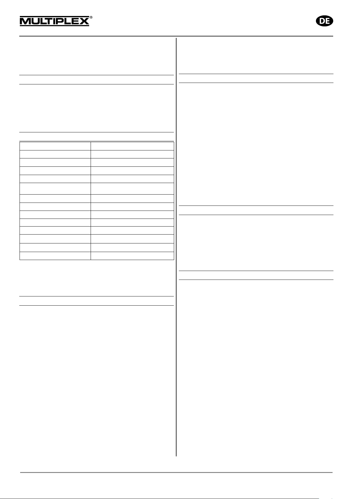
PERMAX BL-O 2816-0900 – bürstenloser Außenläufer
! Diese Bedienungsanleitung ist Bestandteil des
Produktes. Sie beinhaltet wichtige Informationen und
Sicherheits-hinweise. Sie ist deshalb jederzeit griffbereit
aufzubewahren und bei der Weitergabe des Produktes an
Dritte mitzugeben.
1. EINLEITUNG
PERMAX Brushless Motoren werden nach den hohen
Standards für qualitätsbewusste Modellsportler gefertigt.
Optimiert auf geringes Gewicht, hohen Wirkungsgrad, hohes
Drehmoment und Langlebigkeit sind PERMAX Brushless
Motoren die richtige Wahl für den preisgünstigen Antrieb von
RC-Modellen.
2. TECHNISCHE DATEN
BL-O 2816-0900
33 3112
/V:
wicht:
Der PERMAX Brushless Motor BL-O 2816-0900 ist für den
Einsatz in 3D-Modellen bis ca. 500 g Abflugmasse, für
Kunstflugmodelle bis ca. 800 g oder Trainermodelle bis ca. 1300
g, sowie für Segelflugmodelle bis ca. 2000 g konzipiert.
3. SICHERHEITSHINWEISE
• Vor erster Inbetriebnahme Anleitung lesen
• Prüfen Sie vor jeder Inbetriebnahme den festen Sitz des
Motors und der Luftschraube
• Akku nur bei eingeschalteter RC-Anlage an den Motorregler
anschließen, achten Sie darauf, dass der Steuerknüppel für
die Motorsteuerung auf „AUS“ steht
• Motor niemals in der Hand anlaufen lassen
• Bei der Montage des Motors die maximal erlaubte Einschraub-
tiefe beachten
• Entfernen Sie vor Anlaufen lassen des Antriebes alle leicht
ansaugbaren Gegenstände aus dem Ansaugbereich der Luftschraube
• Schützen Sie den Motor vor Schmutz und Feuchtigkeit
• Achten Sie darauf, dass keinerlei Fremdkörper in den Motor
gelangen
• Halten Sie sich während des Betriebes nicht vor oder in der
Drehebene der Luftschraube auf
• Zulässige Höchstdrehzahl des Motors und der Luftschraube
nicht überschreiten
10 A – 14 A
18 A
72 g
200 W
15.000 Umin-1
65° C
19 / 16 mm / 4 x M3
• Stoppen Sie den Motor sofort falls Vibrationen auftreten,
klären Sie vor dem nächsten Anlauf die Ursachen für die
Vibrationen, ggf. müssen Sie die Luftschraube wuchten
• PERMAX Brushless Motoren niemals direkt an eine Stromquelle anschließen, dies zerstört den Motor
4. BETRIEBSHINWEISE
PERMAX Brushless Motoren benötigen einen sensorlosen
Regler für bürstenlose Antriebe. Sollte der Motor in die verkehrte
Richtung drehen, klemmen Sie zur Vermeidung von Kurzschlüssen den Antriebsakku ab und vertauschen Sie beliebige
zwei Kabel zwischen Motor und Regler.
Biegen Sie die Motorkabel nicht extrem und verlegen Sie diese
schwingungsgeschützt.
Kürzen Sie die motorseitigen Anschlusskabel nicht, löten Sie die
montierten Stecker ab, falls Sie andere verwenden wollen.
Sorgen Sie für ausreichende Kühlung von Motor und Regler im
Betrieb. Die max. Belastung des Motors ist nur kurzzeitig, für
maximal 15 Sekunden zulässig. Dabei darf die max. Gehäusetemperatur von 65° C nicht überschritten werden.
Verwenden Sie zur Schonung der Lager und zum Schutz vor
Vibrationen nur ausgewuchtete Luftschrauben.
5. WARTUNGSHINWEISE
Bürstenlose Motoren sind weitgehend wartungsfrei. Geringer
Aufwand verlängert jedoch die Lebensdauer:
Schützen Sie den Motor vor Staub und Schmutz, insbesondere
die Kugellager. Verschmutzte Lager kön nen sich festfressen.
Schmieren Sie deshalb die Lager regelmäßig mit dünnflüssigem
Öl. Tauchen Sie den Motor nicht in Wasser oder Lösungsmittel.
6. TIPPS ZUR SYSTEMAUSLEGUNG
Die Auswahl des Motors und die Auslegung des Antriebes
richten sich nach dem Modelltyp bzw. Einsatzzweck und dem
Gesamtgewicht und der Fluggeschwindigkeit des Flugmodells.
Als Grundlage für die Antriebsauslegung empfehlen wir:
• ca. 100 Watt/kg Eingangsleistung für Segler
• ca. 150 Watt/kg für Trainermodelle
• ca. 250 Watt/kg für Kunstflugmodelle
• ca. 400 Watt/kg für 3D-Kunstflugmodelle
Abhängig vom Gesamtgewicht und der Art des Modells kann die
benötigte Leistung berechnet werden. Die notwendige
Stromaufnahme erhalten Sie, indem Sie die benötigte
Eingangsleistung durch die vorgesehene Eingangsspannung
teilen. I [A] = P [W] / U [V]
Legen Sie für die Berechnung der vorgesehenen Eingangsspannung 90 % der nominalen Akkuspannung zu Grunde, für
eine NiXX-Zelle also 1,1 Volt, für eine LiPo-Zelle 3,3 Volt.
Als Orientierung bei der Auswahl der passenden Luftschraube
dienen die nachfolgenden Diagramme. Die Luftschraubengröße
ergibt sich aus der Betriebsspannung und der errechneten
Stromaufnahme.
Beachten Sie dabei, dass ein Kunstflug-, Trainer- oder 3DKunstflugmodell (relativ langsam fliegend, mehr Schub
erwünscht) eine ganz andere Luftschraube als ein Modell
benötigt, das sehr schnell fliegen soll.
Anleitung PERMAX BL-O 2816-0900 (14-03-28/BRAN) # 82 5881 Irrtum und Änderung vorbehalten! MULTIPLEX
MULTIPLEX Modellsport GmbH & Co.KG • Westliche Gewerbestraße 1 • D-75015 Bretten • www.multiplex-rc.de Seite 1/2
Page 9
Bedienungsanleitung
PERMAX BL-O 2816-0900 – bürstenloser Außenläufer
Für relativ langsam fliegende Modelle sind Luftschrauben mit
einem Durchmesser-Steigungs-Verhältnis (D/S) von bis zu 2:1
(etwa 7“ x 4“ oder 8“ x 4“) zu verwenden.
Flugmodelle, die für hohe Geschwindigkeiten konstruiert sind,
benötigen Luftschrauben mit einem D/S von bis zu 1:1
(z.B. 5“ x 5“). Den höchsten Standschub erreicht man mit einem
D/S von 2:1, die höchste Geschwindigkeit mit einem D/S von
1:1. Dabei ist stets die Höchstdrehzahl des Motors und der gewählten Luftschraube zu beachten!
Beispiel: Antriebsauslegung e ines Trainermodells
mit einem Gesamtgewicht von ca. 1,0 kg unter
Verwendung des PERMAX BL-O 2816-0900
Durch das Gesamtgewicht von 1,0 kg und der Art des Modells
ergibt sich eine notwendige Eingangsleistung von (1,0 kg x 150
Watt/kg ) ca. 150 Watt.
Wir nehmen an, Sie wollen Ihr Modell mit einem 3S LiPo Pack
betreiben, (90 % der Nominalspannung von 3,7 V/Zelle x 3
Zellen ) mit 9,9 Volt. Daraus ergibt sich der notwendige Strom
von (150 Watt / 9,9 V ) ca. 15 A.
Da es sich um ein relativ langsam fliegendes Modell handelt,
würden Sie eine Luftschraube mit einem D/S Verhältnis von ca.
2:1 wählen. Dies bedeutet, Sie benötigen eine Luftschraube von
ca. 11“ x 4,7“.
Messen Sie jedoch trotzdem immer die Drehzahl sowie die
Stromaufnahme Ihres Motors unter Last bei Vollgas. Eine zu
hohe Leistungsaufnahme kann zu einer Überhitzung des Motors
führen.
7. GEWÄHRLEISTUNG
Für unsere Produkte leisten wir entsprechend den derzeit
geltenden gesetzlichen Bestimmungen Gewähr. Wenden Sie
sich mit Gewährleistungsfällen an den Fachhändler, bei dem Sie
das Gerät erworben haben.
Von der Gewährleistung ausgeschlossen sind Fehlfunktionen,
die verursacht wurden durch:
• Unsachgemäßen Betrieb (z.B. Überhitzung), falsche
Anschlüsse, Verpolung
• Verwendung von nicht originalem MULTIPLEX-Zubehör
• Versehentliche oder absichtliche Beschädigung
• Defekte auf Grund normaler Abnutzung
• Betrieb außerhalb der technischen Spezifikationen
• Veränderungen / Reparaturen, die nicht von MULTIPLEX
oder einer autorisierten MULTIPLEX-Service-Stelle ausgeführt wurden nutzen Sie unseren Service für Reparaturen
8. CE-PRÜFUNG
Die Bewertung der Geräte erfolgt nach europäisch
harmonisierten Richtlinien. Sie besitzen daher ein
Produkt, das hinsichtlich der Konstruktion die
Schutzziele der Europäischen Gemeinschaft zum sicheren
Betrieb der Geräte erfüllt.
Diese Konformitätserklärung kann bei Bedarf bei der
MULTIPLEX Modellsport GmbH & Co.KG angefordert werden.
9. ENTSORGUNGSHINWEISE
Elektrogeräte, die mit der durchgestrichenen
Mülltonne gekennzeichnet sind, zur Entsorgung nicht
in den Hausmüll geben, sondern einem geeigneten
Entsorgungssystem zuführen.
In Ländern der EU (Europäische Union) dürfen Elektrogeräte
nicht durch den Haus- bzw. Restmüll entsorgt werden (WEEE Waste of Electrical and Electronic Equipment, Richtlinie
2002/96/EG). Sie können Ihr Altgerät bei öffentlichen Sammelstellen Ihrer Gemeinde bzw. Ihres Wohnortes (z.B. Recyclinghöfe) abgeben. Das Gerät wird dort für Sie fachgerecht und
kostenlos entsorgt.
Mit der Rückgabe Ihres Altgerätes leisten Sie einen wichtigen
Beitrag zum Schutz der Umwelt!
Anleitung PERMAX BL-O 2816-0900 (14-03-28/BRAN) # 82 5881 Irrtum und Änderung vorbehalten! MULTIPLEX
MULTIPLEX Modellsport GmbH & Co.KG • Westliche Gewerbestraße 1 • D-75015 Bretten • www.multiplex-rc.de Seite 2/2
Page 10

Safety Information for MULTIPLEX model aircraft
GB
This model is NOT A TOY in the usual sense of the term.
By operating the model the owner afrms that he is aware of the content of the operating instructions, especially those
sections which concern safety, maintenance, operating restrictions and faults, and is capable of fullling these requirements.
This model must not be operated by any child under fourteen years of age. If a person below this age operates the model
under the supervision of a competent adult who is acting as the child’s guardian within the legal sense of the term, this
individual is responsible for the implementation of the information in the OPERATING INSTRUCTIONS.
THE MODEL AND ASSOCIA TED ACCESSORIES MUST BE KEPT OUT OF THE REACH OF CHILDREN UNDER THREE
YEARS OF AGE! MODELS CONTAIN SMALL DETACHABLE PARTS WHICH MAY BE SWALLOWED BY CHILDREN
UNDER THREE YEARS. CHOKING HAZARD!
All the warnings in the OPERATING INSTRUCTIONS must be observed whenever the model is operated. Multiplex
Modellsport GmbH & Co. KG accepts no liability for loss or damage or any kind which occurs as a result of incorrect
operation or misuse of this product, including the accessories required for its operation. This includes direct, indirect,
deliberate and accidental loss and damage, and all forms of consequent damage.
Every safety note in these instructions must always be observed, as all the information contributes to the safe operation of your model. Use your model thoughtfully and cautiously, and it will give you and your spectators many hours of
pleasure without constituting a hazard. Failure to operate your model in a responsible manner may result in signicant
property damage and severe personal injury. You alone bear the responsibility for the implementation of the operating
instructions and the safety notes.
Approved usage
The model is approved exclusively for use within the modelling hobby. It is prohibited to use the model for any other
purpose than that stated. The operator of the model, and not the manufacturer, is responsible for damage or injury of
any kind resulting from non-approved use.
The model may only be operated in conjunction with those accessories which we expressly recommend. The recommended components have undergone thorough testing, are an accurate match to the model, and ensure that it functions
safely . If you use other components, or modify the model, you operate it at your own risk, and any claim under guarantee
is invalidated.
To minimise the risk when operating the model, please observe the following points:
The model is guided using a radio control system. No radio control system is immune to radio interference, and
such interference may result in loss of control of the model for a period of time. To avoid collisions, you must
therefore ensure at all times that there is a wide margin of safety in all directions when operating your model. At
the slightest sign of radio interference you must cease operating your model!
Never operate your model until you have successfully completed a thorough check of the working systems, and
carried out a range-check as stipulated in the instructions supplied with your transmitter.
The model may only be own in conditions of good visibility. You can avoid being temporarily blinded by not ying
towards the sun, or in other difcult light conditions.
A model must never be operated by a person who is under the inuence of alcohol, drugs or medication which
have an adverse effect on visual acuity and reaction time.
Only y your model in conditions of wind and weather in which you are able to maintain full control of the model.
Even when the wind is light, bear in mind that turbulence can form at and around objects which may have an
effect on the model.
Never y in any location where you may endanger yourself of others, e.g. close to residential areas, overhead
cables, open roads and railway lines.
Never y towards people or animals. You may think that ying low over other people’s heads is proof of your
piloting skill, but all it does is place others at unnecessary risk. It is in all our interests that you let other pilots
know that this is what you think. Always y in such a way that you do not endanger yourself or others. Bear in
mind that even the best RC system in the world is subject to outside interference. No matter how many years of
accident-free ying you have under your belt, you have no idea what will happen in the next minute.
10
Page 11
GB
Residual risks
Even if the model is operated in the correct manner, and you observe all safety aspects, there is always a certain residual
risk.
For this reason it is mandatory to take out third-party liability insurance. If you join a club or ying association, insurance
is usually available or included in the annual fee. Make sure that your insurance cover is adequate (i.e. that it covers
powered model aircraft). Always keep your models and your radio control equipment in perfect order.
The following hazards may occur owing to the model’s construction and type:
Injury caused by the propeller: you must keep well clear of the area around the propeller from the moment that
the battery is connected. Please bear in mind that objects in front of the propeller may be sucked into it, and
objects behind the propeller may be blown away by it. The model may start moving when the propeller starts
to turn. You must therefore position the model in such a way that it cannot move towards other persons if the
motor should unexpectedly start running. When you are carrying out adjustment work involving the running
motor, you must ensure that the model is always held securely by an assistant.
Crash caused by pilot error: this can happen even to the best of pilots, so it is essential to y exclusively in a
safe environment: an approved model ying site and suitable insurance are basic essentials.
Crash caused by technical failure or unnoticed damage in transit or in the workshop. A thorough check of the
model before every ight is essential. However, you should also take into account at all times that material
failures can and do occur. Never y in a location where your model may damage or injure others.
Keep within the stated operating limits. Excessively violent ying will weaken the airframe, and may result in
sudden material failure, or may cause the model to crash during a subsequent ight due to “creeping” conse-
quent damage.
Fire hazard caused by electronic failure or malfunction. Store batteries safely, and always observe safety
notes which apply to the airborne electronic components, the battery and the battery charger. Protect all electronic equipment from damp. Ensure that the speed controller and battery are adequately cooled.
The instructions which accompany our products must not be reproduced and / or published, in full or in part, in
print or any electronic medium, without the express written approval of Multiplex Modellsport GmbH & Co. KG.
11
Page 12
RR FunGlider # 26 4273
Examine your kit carefully!
MUL TIPLEX model kits are subject to constant quality checks throughout the production process, and we sincerely hope
that you are completely satised with the contents of your kit. However, we would ask you to check all the parts (referring
to the Parts List) before you start construction, as we cannot exchange components which you have already modied. If
you nd a part is not acceptable for any reason, we will gladly correct the defect or replace the item in question once we
have inspected it. Please send the component to our Service Department, with adequate postage pre-paid, being sure to
include the completed complaints form. We are constantly working on improvements to our models, and for this reason
we must reserve the right to change the kit contents in terms of shape or dimensions of parts, technology , materials and
ttings, without prior notication. Please understand that we cannot entertain claims against us if the kit contents do not
agree in every respect with the instructions and the illustrations.
Caution!
Radio-controlled models, and especially model aircraft, are by no means playthings in the usual sense of the
term. Building and operating them safely requires a certain level of technical competence and manual skill,
together with discipline and a responsible attitude at the ying eld.
Errors and carelessness in building and ying the model can result in serious personal injury and damage to property.
Since we, as manufacturers, have no control over the construction, maintenance and operation of our products, we are
obliged to take this opportunity to point out these hazards and to emphasise your personal responsibility.
Warning:
Like every aeroplane, this model has static limits. Steep dives and senseless manoeuvres inappropriate to the type
may result in the loss of the aircraft. Please note: we will not replace the model in such cases. It is your responsibility to
approach the airframe’s limits gradually. It is designed for the power system recommended in these instructions, but is
only capable of withstanding the ight loads if built exactly as described and if it is in an undamaged state.
GB
The model is supplied pre-assembled and virtually ready to y. The model can be ready for the air very quickly. Please take
the time to read through the Instructions before completing and ying the model, paying particular attention to the Safety
Notes and Tips. To complete the model’s equipment you will need a receiver and ight battery. For our recommended
items please refer to the Instructions. For additional items (e.g. transmitter, battery charger etc.) refer to the current
catalogue or the MPX website at: www.multiplex-rc.de
Parts List
Part-No No.off Description Material Dimensions
1 1 Panda Sport KIT building instructions
3 * 1 Fuselage, assembled * Moulded Elapor foam Ready made
5 * 1 L.H. wing panel * Moulded Elapor foam Ready made
6 * 1 R.H. wing panel * Moulded Elapor foam Ready made
7+8 1 Tailplane Moulded Elapor foam Ready made
30 50 Trim ballast Metal balls Ø4mm / 15g
32 1 Trim ballast Metal balls Ø13mm / 9 g
20 2 Velcro tape, “hook” Plastic 25 x 60 mm
21 2 Velcro tape, “loop” Plastic 25 x 60 mm
28 1 Allen key Metal 1.5 mm A/F
* With four factory-tted Nano-S (UNI) servos, including all control surface linkages, Brushless motor PERMAX BL-O
2816-0900, controller MULTIcont BL-20 SD and assembled 9x6” folding propeller.
Airborne radio control system components / other accessories
Recommended equipment:
MULTIPLEX receiver, min. RX-5 light M-LINK Order No. 5 5808
or RX-5 M-LINK receiver, telemetry-capable Order No. 5 5817
With this receiver you can also use the telemetry modules, and equip your model
with sensors such as the vario / altimeter sensor and current sensor (electronic fuel gauge).
Recommended Flight battery
Flight battery Li-BATT FX 3/1-950 (M6) Order No. 15 7321
Adhesives:
Zacki ELAPOR ® 20 g Order No. 59 2727
Zacki ELAPOR ® Super liquid 10 g Order No. 59 2728
Battery charger HiTEC Multicharger X1 AC Plus, with Order No. 114 118
AC/DC 100-240V/10-18V 6,0A
12
Page 13

Important note
This model is not made of Styrofoam™, and it is not possible to glue the material using white glue, polyurethane or
epoxy; these adhesives only produce supercial joints, and simply break away under stress. Please be sure to use
medium-viscosity cyano-acrylate glue exclusively, preferably Zacki ELAPOR® # 59 2727, which is optimised specically
for ELAPOR® particle foam. If you se Zacki ELAPOR® there is usually no need for cyano ‘kicker’ or activator. However,
if you wish to use a different adhesive which requires the use of activator, please note that these materials are injurious
to health, and should always be applied in the open air. Take care when handling all cyano-acrylate adhesives, as they
harden in seconds, so don’t get them on your ngers or other parts of the body. We strongly recommend the use of
goggles to protect your eyes. Keep the adhesive out of the reach of children! For certain joints it is also possible to use
hot-melt adhesive; the instructions indicate where this is the case.
Working with Zacki ELAPOR®
Zacki ELAPOR® has been developed specically for glued joints in our models which consist of moulded ELAPOR®
foam parts.
Please observe the following points in order to obtain perfect joints:
• We advise leaving joined parts for 24 hours to obtain maximum strength, particularly when the glued area is large.
• Activator should only be used for temporary, small-area joints (‘tacking’). Spray a little activator on one surface, and
allow it to air-dry for about thirty seconds.
• To obtain maximum joint strength you should lightly sand the surface with 320-grit abrasive paper before applying glue.
• The adhesive will harden more quickly if you moisten one surface very slightly; in most cases activator (kicker) is then
not required. All you have to do is moisten the mating surface very lightly with a damp cloth or sponge.
Bent parts - actually don’t exist. If you nd that a component has taken up a curve, perhaps after being transported,
it is easy to straighten again. In this respect ELAPOR® behaves in a similar way to metal: bend the component
back slightly beyond the correct position, and the material will then spring back to its proper shape when released,
and maintain it. There are limits, however - don’t overdo it!
Bent parts - really do exist. If you wish to paint your model, apply MPX Primer # 60 2700 to the surfaces, wiping it on
very lightly as if you were cleaning the model. Paint must always be applied thinly and evenly , otherwise the component
will warp. Then you really will have bent parts, and they will also be heavy and perhaps even unusable. We have found
that matt-nish paints produce the best visual effect.
We recommend using our “ELAPOR® Color” range of spray cans # 60 2701 - # 60 2712 (surfaces must be given a coat
of MULTIPrimer # 60 2700 beforehand).
Specication: FunGlider
Wingspan 1300 mm
Overall length 800 mm
All-up weight min. 590 g
Wing area approx.20,5 dm² (FAI)
Wing loading min. 28,9 g/dm²
RC functions:
Ailerons, elevator, rudder, throttle
The Centre of Gravity should be located 57 mm aft of the root leading edge of the wing. The position is indicated by
small pimples on the underside of both wing roots.
1. Before starting construction
Check the contents of your kit before starting work on the
model. You will nd Figs. 1 + 2 and the Parts List helpful
at this stage.
2. Installing the receiving system components
The positioning of the RC components has a minor but
useful effect on the model’s Centre of Gravity. Final
balancing is carried out later by tting trim ballast (metal
balls) in the holes in the n.
to the fuselage side at the front, below the speed controller,
again using hook-and-loop tape. Group the cables together
neatly, and x them to the fuselage side using hot-melt
adhesive or adhesive tape.
Fig. 3
Note: since the “grip” of the hook-and-loop tape is greater
than the adhesion between the sticky coating and the foam
surface, we recommend gluing the tape in place using hot-
melt adhesive or Zacki ELAPOR® (cyano-acrylate).
Install the M-LINK receiver (RX) in the bottom of the
fuselage, in the empty space aft of the servos. Route the
aerial out of the cooling air exit opening, and tape it to the
fuselage. The Li-BATT FX 3/1-950 ight battery can be xed
3. Folding propeller blades
Tighten the screws just to the point where there is no lost
motion (slop) in the propeller blades, but they still fold back
smoothly.
Fig. 4
13
Page 14

4. Initial test-run of the motor
Note: do not connect the ight battery to the speed controller
until you have switched on your transmitter, and are certain
that the control which operates the motor is at the “OFF”
position.
Check the direction of rotation of the motor using your radio
control transmitter and the ight battery: when viewed from
the tail, the motor shaft must spin clockwise (to the right).
If that is not the case, swap over any two of the three wires
attached to the motor.
5. Aileron servos
The output arms on the servo shafts, angled forward by
two splines relative to the case sides (the servos as a
mirror-image pair). This arrangement provides mechanical aileron differential, if your transmitter does not feature
suitable electronic facilities (differential mixer). Angling the
output arms in this way ensures by mechanical means that
the up-travel of the ailerons is greater than their down-travel. You also can get then more up-travel for spoiler.
Fig. 5
8. Setting the control surface travels (recommended
values only!)
The control surface deections must be set correctly if the
model is to respond in a harmonious manner to control
commands. The travels are measured at the widest point
of each control surface.
Aileron: 12 / 6 mm +/Elevator: 10 / 10 mm +/Rudder: 15 / 15 mm +/-
Spoiler: 14 mm (both ailerons up)
Elevator compensation:
Spoilers: 3,5 mm „down“
Power: 1 mm „down“
The tailplane is at the correct neutral point when the sockethead grubscrew is visible through the hole in the side of the
fuselage. Be sure to set the elevator servo exactly to centre
before you tighten the grubscrew!
Fig. 10
Tip: if the hinge line should tear at any time, a drop or two
of cyano will repair the damage.
6. Trial-tting the wings in the fuselage
The wing panels can now be plugged into the fuselage.
The wings are separated by pulling the lug forward towards
the wing leading edge with one finger, until the teeth
disengage.
Fig. 6
Note: if the wing retainer system should become loose
after you have own the model for a while, push the wings
together slightly more rmly: this will engage one further
tooth, and the joint will become rm again.
Temporarily t the tailplane panels on the fuselage by
pushing them together until the latch engages.
Fig. 7
Note: Tailplane
T o dismantle the system, locate the point marked “X” on the
tailplane 8, and press it in to release the retainer.
Fig. 8
It is essential that the tailplane should pivot freely. If the
panels rub against the n, it may be necessary to compress
the foam slightly at the root face of the tailplane panels. The
easiest method of doing this is to place the root face of the
tailplane panel on the edge of a table, and slide it to and
fro using moderate pressure. Alternatively the foam can be
trimmed back very slightly using a balsa knife.
7. Checking the model
Assemble the model completely, and ensure that the
airframe is “straight and square”. All the receiving system
components must be installed and connected correctly.
Check the control surface travels and the direction of
rotation of the servos. Ensure that all the mechanical control
systems are free-moving. Check that the wires attached to
the motor cannot make contact with the rotating section of
the motor or the servo output arms (if in doubt: glue them!).
With the propeller tted, carefully check once more that the
motor rotates in the correct direction.
Figs. 9
14
The “Spoiler” function is designed to shorten the landing
approach by deecting both ailerons up simultaneously.
At the same time the appropriate down-elevator trim is
mixed in, so that the model maintains a stable attitude.
This function can only be implemented if your radio control
system features suitable mixer facilities. Please refer to the
instructions supplied with your RC system for details of this.
Note: when you apply a right-aileron command, the righthand aileron - as seen from the tail, looking forward - must
deect up.
If you wish to give your new model a coloured nish, we
recommend our range of “ELAPOR® Color” spray cans #
60 2701 - # 60 2712. Note that the foam surfaces must be
given a coat of MULTIPrimer # 60 2700 beforehand.
You will nd further information and tips on using “ELAPOR®
Color” spray paints in the FAQ section on our website.
9. Setting the Centre of Gravity
The correct Centre of Gravity can be set by adjusting the
position of the speed controller and ight battery, and by
adding ballast if required. The CG should be located 57 mm
back from the wing leading edge, measured where the wings
meet the fuselage; the position is indicated by small raised
pimples on the underside of the wings. Support the fully
assembled model on two ngertips: if balanced correctly,
the fuselage should now remain horizontal, with the nose
inclined slightly down.
If necessary, add trim ballast 30 / 32 to the chambers in
the n, then cover the recesses with the stickers from the
decal sheet.
Fig. 11 + 12
10. Pre-ight preparations
For the first flight please wait for a day with as little
breeze as possible; it is often worth waiting for the quieter
evening hours. If you are a beginner to radio-controlled
model aircraft, we strongly recommend that you ask an
experienced modeller to help you, as it is extremely likely
that things will go wrong if you try to “go it alone”. If in
doubt, contact your local model ying club. Your nearest
model shop will also be able to supply the address of clubs
in your area.
Page 15

It is essential to carry out a range-check before ying the
model for the rst time. When you do this it is important to
keep to the procedure recommended by the radio control
system manufacturer.
Be sure to give your transmitter battery and ight battery a
full charge in accordance with the battery manufacturer’s
recommendations before ying the model. If you are not
using a 2.4 GHz radio control system, check that “your”
channel is not already in use.
If you are unsure of anything, please don’t risk a ight. It is
far better to pack up the whole system (including battery,
switch harness and servos) and send it to the manufacturer’s
Service department for checking.
11. Maiden ight …
The aircraft is designed to be hand-launched (always into
wind).
If you are a beginner to model ying, we strongly recommend
that you ask an experienced modeller to help you for the
rst few ights. Once the model has reached a safe height,
adjust the control surfaces using the trims on the transmitter,
so that the model ies straight and level “hands-off”.
Powered version: with the aircraft ying at an adequate
altitude, check how it responds when the motor is switched
off, so that you are familiar with its behaviour on the glide.
Carry out repeated simulated landing approaches at a safe
height, as this will prepare you for the real landing when the
battery is discharged.
Avoid ying tight turns at rst, especially close to the ground,
and in particular during the landing approach. It is always
better to land safely some distance away than to risk a crash
by forcing the model back to your feet.
12. Slope soaring
Ridge soaring is an extremely attractive form of model ying.
Staying aloft for hours on end in slope lift, without needing
any outside aid for launching, must be one of the nest
of modelling experiences. The last word in model ying
is thermal ying from the slope: launch the model, y out
over the valley, search for a thermal, locate the lift, circle
up, “milking” it to the limits of vision (take care - the model is
small!), and then bring it down again in a continuous series
of aerobatic manoeuvres, and then repeat the whole show
- that must surely be one of the greatest of all pleasures
in modelling. At the same time the electric power system
provides a means of bringing the model “back home” at any
time if the lift should fail, thereby eliminating the old fear of
“landing out” in the valley.
13. Trainer mode operations
The good-natured ying characteristics of the FunGlider,
combined with the long ight times it offers, make the model
ideal as a practice machine. With the wireless Trainer Stick
# 4 5183, two MUL TIPLEX transmitters and an experienced
tutor, the beginner can swiftly learn the art of model ying
without wrecking model after model. Most pupils are capable
of controlling the model by themselves after just a short
period of tuition.
Any 2.4 GHz M-LINK transmitter can be used as Pupil
transmitter, while the Teacher transmitter can be any
MULTIPLEX transmitter featuring a DIN multi-function
socket and Teacher functionality - regardless of the
frequency band, i.e. 2.4 GHz M-LINK* or xx MHz. There
is no connecting lead to hinder the pilots’ movements, and
the teacher and pupil can even stand apart (20 - 30 metres)
if necessary.
14. Flight simulator
MULTIight is our tip for unlimited ying fun - and you don’t
have to spend a single penny! Nevertheless it’s exciting,
and set in a realistic 3D landscape.
MULTIPLEX offers you the high-quality MULTIight ight
simulator as a great platform for practising the art of model
ying. Download under www.multiplex-rc.de
If you are thinking about buying a Multiplex model helicopter
or xed-wing aircraft, the simulator gives you the chance to
try out various types before making up your mind. You can
test the models thoroughly in a realistic ying environment.
The 3D landscape provides the background scenery of a
typical model ying site.
The simulator can be controlled using a joystick, a game
controller or an RC system transmitter with interface.
The software is particularly convenient for owners of a
MUL TIPLEX M-LINK system, as they can control the model
on the PC wirelessly using the MULTIight Stick.
With MULTIight you can polish your ying skills without
any risk of damaging the model. All the models feature
highly realistic ying characteristics, allowing you to gain
invaluable experience - particularly when it comes to the
critical ying situations such as: stalls, torque-rolls, positive
and negative snap-rolls, etc.
15. Safety
Safety is the First Commandment when ying any model
aircraft. Third party insurance is mandatory. If you join a
model club, suitable cover will usually be available through
the organisation. It is your personal responsibility to ensure
that your insurance is adequate (i.e. that its cover includes
powered model aircraft). Make it your job to keep your
models and your radio control system in perfect order at all
times. Check and observe the correct charging procedure
for the batteries you are using. Make use of all sensible
safety systems and precautions which are advised for
your system. An excellent source of practical accessories
is the MULTIPLEX main catalogue or our website www.
multiplex.de
MULTIPLEX products are designed and manufactured
exclusively by active modellers for practising modellers.
Always y with a responsible attitude. You may think that
ying low over other people’s heads is proof of your piloting
skill; others know better. The real expert does not need to
prove himself in such childish ways. Let other pilots know
that this is what you think too, as it is in all our interests.
Always y in such a way that you do not endanger yourself
or others. Bear in mind that even the best RC system in
the world is subject to outside interference. No matter how
many years of accident-free ying you have under your
belt, you have no idea what will happen in the next minute.
Before every ight, check that the battery, the wings
and the tailplane are attached and rmly seated. Check
in turn that each control surface is operating correctly!
We - the MUL TIPLEX team - hope you have many hours of
pleasure building and ying your new model.
MULTIPLEX Modellsport GmbH &Co. KG
15
Page 16

Operating Instructi ons
Type:
BL-O 2816-0900
#
RPM / V:
Cell count
NiXX / LiPo:
Optimum working range:
10 A – 14 A
Max. current for 15 sec.:
18 A
Shaft Ø:
Diameter:
Length:
31 mm
Weight:
72 g
Max. output:
200 W
Max. r ot
Max. case temperature:
Mounting:
∅ 19 / 16 mm / 4 x M3
PERMAX BL-O 2816-0900 – brushless outrunner motor
! These operating instructions are an integral part of this
product. They contain important information and safety
notes, and should be kept in a safe place at all times. Be
sure to pass them on to the new owner if you ever dispose
of the product.
1. INTRODUCTION
PERMAX motors are manufactured to high standards for qualityconscious modellers. Carefully optimised for low weight, high
efficiency, high torque and durability, PERMAX brushless motors
are the perfect choice as power plants for RC models.
2. SPECIFICATION
33 3112
ational speed:
PERMAX BL-2816-0900 brushless motor is designed for use in
3D models with an all-up weight of up to about 500 g, for
aerobatic models weighing up to about 800 g and trainers up t o
around 1300 g. They also are suitable for powered gliders
weighing up to around 2000 g.
3. SAFETY NOTES
• Read the instructions before using the motor for the first time
• Check that the motor and propeller are firmly attached before
every flight
• Do not connect the battery to the speed controller until you
have switched the RC system on, and checked that the throttle
stick is at the “OFF” position
• Never run the motor whilst holding it in your hand
• Do not exceed the stated maximum screw depth when
installing the motor
• Remove all loose, lightweight objects from the area in front of
the propeller before running the motor, as they may be sucked
into the propeller
• Protect the motor from dirt and damp
• Ensure that no foreign bodies get inside the motor
• When the motor is running, do not stand in front of the
propeller plane or in line with it
• Do not exceed the maximum permitted rotational speed of the
motor and propeller
900
7 - 12 / 2S - 4S
4,0 mm
28 mm
15.000 Umin-1
65° C
• Stop the motor immediately if you notice vibration, and
eliminate the cause before running it again. You may need to
balance the propeller
• PERMAX brushless motors must never be connected directly
to a power source, as this will wreck the motor
4. OPERATING NOTES
PERMAX brushless motors must only be run in conjunction with
a sensorless controller for brushless motors. If the motor shaft
spins in the wrong direction, disconnect the battery (to avoid
short-circuits) and swap over any two of the leads between the
motor and the speed controller.
Do not bend the motor leads sharply. Deploy them in such a way
that they are not subjected from vibration and oscillation.
Do not shorten the wires attached to the motor. If you wish to
use different connectors, unsolder the ex isting one s.
Ensure that the motor and speed controller are adequately
cooled when running. The maximum motor load may only be
used briefly, i.e. no more than fifteen seconds. At the same time
the maximum case temperature of 65°C must not be exceeded.
Use properly balanced propellers only, as this avoids vibration
and premature bearing damag e.
5. MAINTENANCE NOTES
Brushless motors are largely maintenance-free, but a little care
will ensure that they last a very long time:
Protect the motor from dust and dirt - especially the ball races.
Soiled bearings may jam, and they will then need to be replaced.
For this reason lubricate the bearings with thin oil at regular
intervals. Do not immerse the motor in water or solvent.
6. TIPS FOR POWER SYSTEM DESIGN
The selection of the motor and the design of the power system
must reflect the model type, the kind of flying envisaged, the
model aircraft’s all-up weight, and its flying speed.
We suggest these basic rules for power system design:
• approx. 100 Watt / kg input power for electric gliders
• approx. 150 Watt / kg for trainer models
• approx. 250 Watt / kg for aerobatic models
• approx. 400 Watt / kg for 3-D aerobatic model s
You can calculate the power required if you know the model’s
all-up weight and general type. The current drain required is
found by dividing the required input power by the input voltage
available. I [A] = P [W] / U [V]
When calculating the input voltage take 90% of the nominal
battery voltage as the basis: 1.1 Volts for one NiXX cell, and 3.3
Volts for one LiPo cell.
The following diagrams are designed to help you select the
appropriate propeller. The propeller size varies according to the
operating voltage and the calculated current drain.
Please note that an aerobatic model, a 3-D aerobatic type or a
trainer (relatively slow flying, more thrust required) calls for an
entirely different propeller to a model which is to fly very fast.
PERMAX BL-O 2816-0900 instructions (14-03-28/BRAN) # 82 5881 Errors and omissions excepted MULTIPLEX
MULTIPLEX Modellsport GmbH & Co.KG • Westliche Gewerbestraße 1 • D-75015 Bretten • www.multiplex-rc.de Page 1/2
Page 17

Operating Instructi ons
PERMAX BL-O 2816-0900 – brushless outrunner motor
For relatively slow-flying models the propeller should have a
diameter: pitch ratio (D:P) of up to 2:1 (typically a 7” x 4” or 8” x
4”).
Model aircraft designed for high-speed flying need propellers
with a D:P of up to 1:1 (e.g. 5” x 5”). Maximum thrust is achieved
with a D:P of 2:1, maximum speed with a D:P of 1:1.
When making these calculations always keep within the
maximum permissible rotational speeds stated for the motor and
propeller.
Example: Typical power system for an trainer model with an
all-up weight of around 1,0 kg, using the PERMAX
BL-O 2816-0900
From the flying weight of 1,0 kg and the type of model we see
that the input power should be (1,0 kg x 150 Watt / kg )
approx. 150 Watts.
Let us assume that you want to use a 3S LiPo battery. 90% of
the nominal voltage (3.7 Volts / cell x 3 cells) is 9.9 Volts. This
gives the required current of (150 W atts / 9.9 Volts), or around
15,1 A.
As this is a model with a relatively low airspeed, you would
select a propeller with a D:P ration of around 2:1. This means:
you need a propeller of around 11“ x 4,7“.
Despite the careful calculations, always measure the speed and
current drain of your motor under load at full throttle. Overloading a motor may result in overheating and damage.
7. GUARANTEE
Our products are covered by the currently valid statutory
guarantee regulations. If you wish to make a claim under
guarantee, please contact the model shop where you purchased
the product in the first instance.
The guarantee does not cover faults and defects which are
caused by the following errors:
• Improper operation (e.g. overheating), incorrect connections,
reversed polarity
• Use of accessories other than genuine MULTIPLEX items
• Accidental or deliberate damage
• Faults due to normal wear and tear
• Operating the motor outside the technical specification
• Modifications / repairs which were not carried out by
MULTIPLEX or an authorised MULTIPLEX Service Centre
always use our official service for repairs
8. CE APPROVAL
This product has been assessed in accordance with the
relevant harmonised European directives. You are
therefore the owner of a product whose design fulfils the
protecti ve aims of t he European Community relating to the safe
operation of equipment.
You are entitled to see a copy of this Conformity Declaration.
Please contact MULTIPLEX Modellsport GmbH & Co.KG if you
wish to do this.
9. DISPOSAL INFORMATION
Electrical equipment marked with the cancelled
waste bin symbol must not be discarded in the
standard household waste; instead it must be taken
to a suitable specialist disposal system.
In the countries of the EU (European Union) electrical equipment
must not be discarded via the normal domestic refuse system
(WEEE - W aste of Electrical and Electronic Equipment, directive
2002/96/EG). You can take unwanted equipment to your nearest
local authority waste collection point or recycling centre. There
the equipment will be disposed of correctly and at no cost to
you.
By returning your unwanted equipment you can make an
important contribution to the protection of the environment.
PERMAX BL-O 2816-0900 instructions (14-03-28/BRAN) # 82 5881 Errors and omissions excepted MULTIPLEX
MULTIPLEX Modellsport GmbH & Co.KG • Westliche Gewerbestraße 1 • D-75015 Bretten • www.multiplex-rc.de Page 2/2
Page 18

Consignes de sécurités pour les modèles volants MULTIPLEX
F
Le modèle n’est PAS UN JOUET.
En utilisant ce modèle, le propriétaire de celui-ci déclare avoir pris connaissance du contenu de la notice d’utilisation,
particulièrement concernant les consignes de sécurités, l’entretien ainsi que les restrictions et défauts d’utilisations, et
qu’il a bien compris le sens de ces consignes
Ce modèle ne doit pas être utilisé par des enfants de moins de 14 ans. Si des personnes mineures devaient utiliser ce
modèle sous la surveillance d’une personne responsable, au sens légal du terme, et expérimentée, celui-ci porte donc
la responsabilité concernant le respect des consignes contenu dans la NOTICE D’UTISATION!
LE MODÈLE AINSI QUE T OUT L’ÉQUIPEMENT NÉCESSAIRE DOIT ÊTRE ÉLOIGNÉ DES ENF ANTS DE MOINS DE
3 ANS! LES PARTIES AMOVIBLES DU MODÈLE PEUVENT ÊTRES AVALÉES PAR LES ENFANTS DE MOINS DE 3
ANS. DANGER D’ÉTOUFFEMENT!
Lors de l’utilisation de votre modèle il est impératif de respecter toutes les indications relatives aux dangers décrits dans
la NOTICE D’UTISATION. La société Multiplex Modellsport GmbH & Co. KG ne peut pas être tenue pour responsable
concernant la perte ou tout type d’endommagement de votre modèle résultant à un abus ou une mauvaise utilisation de
ce produit, ainsi que des accessoires. Cela comprend également la perte ou les dommages directs ou indirects, ainsi
que de toute forme de dommages résultants
Chaque consigne de sécurité contenue dans la notice doit obligatoirement être respectée et contribue directement à une
utilisation sécurisée de votre modèle. Utilisez votre modèle intelligemment et avec prudence, cela procurera beaucoup
de plaisir à vous et à vos spectateurs sans pour autant les mettre en danger. Si vous n’utilisez pas correctement votre
modèle, ceux-ci peut conduire à des dommages sur lui-même ou des blessures plus ou moins graves sur vous ou autrui.
Vous seul êtes responsables de la transposition correcte des indications contenues dans la notice
Utilisation conforme
Ce modèle doit exclusivement être utilisé dans le domaine du modèle réduit. Toute utilisation dans un autre domaine
est absolument interdite. Pour tout dommage ou blessure sur des personnes ou des animaux résultant d’une utilisation
non conforme, c’est l’utilisateur qui en porte la responsabilité et non le fabricant.
N’utilisez votre modèle qu’avec les accessoires conseillés. Les composants/accessoires conseillés sont testés sur leur
fonctionnalité et compatibilité par rapport au modèle. Si vous deviez en utiliser d’autres ou modier le modèle, vous
utiliserez celui-ci à vos risques et périls, sans oublier que les différentes garanties constructeur / revendeur ne sont plus
valables.
An de minimiser les risques lors de l’utilisation de votre modèle, il est important de respecter les points suivants:
Le modèle est piloté au travers d’un émetteur. Malheureusement aucun émetteur n’est à l’abri de problèmes
d’émissions. Ce genre de perturbations peut entraîner une perte momentanée du contrôle de votre modèle.
De ce fait, et an de minimiser au maximum les collisions potentielles, il est vital d’utiliser votre modèle d’une
manière la plus sécurisé possible à tout point de vue. Dès que vous semblez détecter la moindre anomalie de
fonctionnement il faut absolument arrêter de l’utiliser!
Vous ne devez réutiliser votre modèle qu’après avoir effectué un test complet de toutes les fonctions ainsi qu’un
test de portée, en fonction des indications de la notice de votre émetteur.
Le modèle ne doit être utilisé que par temps clair et avec une bonne visibilité. Ne volez pas dans le soleil an
de ne pas être ébloui, ou, si la lumière environnante devait être trop faible pour assurer la bonne visibilité de
votre modèle.
Le modèle ne doit pas être utilisé si vous êtes sous l’inuence d’alcool, autres drogues ou médicaments pouvant
alterner votre perception et vos réexes, entraînant ainsi une diminution de votre vitesse de réaction.
Ne volez que par un temps sans vent et par lequel vous ne rencontrez pas de problème pour garder en per-
manence votre modèle sous contrôle. Pensez toujours que, même par faible vent, il peut y avoir des tourbillons
induits par le relief pouvant avoir des inuences sur votre modèle.
Ne volez jamais à des endroits où vous pourriez mettre en danger autrui ou vous-même, par exemple près des
habitations, lignes à haute tension, routes ou vois ferrée.
18
Page 19

Ne volez jamais directement vers les personnes ou animaux. Volez le plus près possible au-dessus de per-
sonnes n’est pas une preuve de votre savoir-faire, mais expose ces personnes inutilement à un danger. Dans
l’intérêt de tous, veillez en informer également les autres pilotes. Volez toujours de telle manière à ce que vous
ne mettiez personne en danger. Pensez toujours que même la meilleure radiocommande peut être perturbée
par des phénomènes externes. A voir beaucoup d’expérience et des années de vols sans problèmes derrière soi
ne garantie pas qu’il n’y en aura pas dans les prochaines minutes de vol.
Risques
Même si votre modèle respecte toutes les consignes de sécurités et est utilisé conformément il persiste toujours un
risque potentiel.
De ce fait une assurance est obligatoire. Si vous vous inscrivez dans un club ou une association, il est possible de
souscrire une telle assurance auprès de ceux-ci. Veillez à ce que celle-ci vous assure sufsamment (modèle avec propulsion). Veillez à toujours bien entretenir votre modèle et votre émetteur.
Les dangers suivants peuvent survenir en relation avec la construction ou la mise en œuvre du modèle:
Blessures par hélice: dès que l’accu de propulsion est branché il faut avoir dégager la zone autour de l’hélice.
Veillez également observer, que tout objet non xé peut être aspiré si posé devant ou soufé si posé derrière
l’hélice par celle-ci. Le modèle peut se mettre en mouvement. De ce fait diriger votre modèle toujours de telle
manière à ce que celui-ci n’aille jamais vers les personnes dans le cas ou le moteur venait à démarrer. Lors
de travaux de réglages, pour lesquels le moteur est en marche ou peut démarrer, il est impératif qu’une tierce
personne tienne votre modèle.
Crash suite à une erreur de pilotage: cela peut arriver au meilleur pilote, de ce fait il faut évoluer dans une zone
sécurisée comme un terrain de modélisme par exemple, et en ayant obligatoirement souscrit une assurance
avec une bonne couverture.
Crash suite à un problème technique ou dommages cachés à cause d’un mauvais transport ou autre raison. La
vérication soigneuse de votre modèle avant chaque vol est une obligation. Néanmoins il faut toujours garder en
mémoire qu’une défaillance du matériel peut survenir à tout moment. De ce fait ne volez jamais à des endroits
où vous risquez de nuire à autrui.
Respectez les limites d’utilisations. Effectuer des manœuvres trop brutales entraîne un stress inutile de votre
modèle et peut avoir comme conséquence une défaillance subite, ou par la suite au travers de dommages
‘’sournois’’, de la structure ou du matériel.
Danger de combustion par défaillance de l’électronique. Stockez vos accus toujours dans un lieu sécurisé,
respectez les consignes de sécurités des composants électroniques dans votre modèle, des accus ainsi que
du chargeur utilisé et protégez l’électronique de toute projection d’eau. Assurez-vous que le régulateur et l’accu
aient un refroidissement sufsant.
T oute reproduction / publication sous forme papier ou électronique, même partielle, des notices de nos différents
produits sont strictement interdit sauf par autorisation exclusive de le société Multiplex Modellsport GmbH &
Co. KG (sous forme écrite).
19
Page 20

RR FunGlider # 26 4273
Familiarisez-vous avec le kit d’assemblage!
Les kits d’assemblages MULTIPLEX sont soumis pendant la production à des contrôles réguliers du matériel. Nous
espérons que le contenu du kit répond à vos espérances. Nous vous prions de vérier le contenu (suivant la liste des pièces) du kit avant l’assemblage, car les pièces utilisées ne sont pas échangées. Dans le cas où une pièce ne serait pas
conforme, nous sommes disposés à la rectier ou à l’échanger après contrôle. Veuillez retourner la pièce à notre unité
de production sans omettre de joindre le coupon de caisse ainsi qu’une petite description du défaut (formulaire de récla-
mation). Nous essayons toujours de faire progresser technologiquement nos modèles. Nous nous réservons le droit de
modications de la forme, dimensions, technologie, matériel et contenu sans préavis. De ce fait, nous ne prenons donc
pas en compte toutes réclamations au sujet des images ou de données ne correspondantes pas au contenu du manuel.
Attention!
Les modèles radiocommandés, surtout volants, ne sont pas des jouets au sens propre du terme. Leur assemblage et utilisation demande des connaissances technologiques, un minimum de dextérité manuelle, de rigueur,
de discipline et de respect de la sécurité.
Les erreurs et négligences, lors de la construction ou de l’utilisation, peuvent conduire à des dégâts corporels ou maté-
riels. Du fait que le fabricant du kit n’a plus aucune inuence sur l’assemblage, la réparation et l’utilisation correcte, nous
déclinons toute responsabilité concernant ces dangers.
Avertissement:
Comme tous les appareils volants votre modèle possède également ses limites statiques! Des vols en piqués ou des
manœuvres irresponsables peuvent entraîner la perte de votre modèle. Veillez noter que dans de tels aucun remplacement sera consenti. Essayez de trouver progressivement les limites de votre modèle. Celui-ci est adapté pour accueillir
la propulsion que nous vous conseillons, néanmoins que suite à un assemblage irréprochable et exempt de tout dom-
mage an de pouvoir résister aux contraintes.
F
Le modèle est pré assemblé et quasiment près à voler. De ce fait, votre modèle est près à l’utilisation en très peu de
temps. Néanmoins, lisez attentivement la notice avant l’assemblage et l’utilisation et respectez les remarques ainsi que
les conseils de sécurités. An d’équipez complètement votre modèle, il vous manque un récepteur et l’accu de propulsion. Vous trouverez dans la notice d’assemblage des indications sur le matériel conseillé, et pour le matériel en annexe
(par ex. : émetteur, chargeur, etc.) veillez vous reporter à notre catalogue général ou visiter notre site Internet sous :
www.multiplex-rc.de
Liste de pièces RR
Nr. Nbr Désignation Matière Dimensions
1 1 Instructions d’assemblage
3* 1 Fuselage pré-assemblé* MousseElapor pièce complète
5* 1 Aile gauche ME pièce complète
6* 1 Aile droite ME pièce complète
7+8 1 Profondeur ME pièce complète
30 50 Ballast de trimm boules métal Ø4mm / 15g
32 1 Ballast de trimm boules métal Ø13mm / 9 g
20 2 Bande Velcro côté crochets Plastique 25x60mm
21 2 Bande Velcro côté velours Plastique 25x60mm
28 1 Clé six pans Métallique SW 1,5
* équipé de 4 servos Nano-S (UNI) avec leurs tringles de commandes, Motor PERMAX BL-O 2816-0900, controller
MULTIcont BL-20 SD et hélice à pales repliables montée 9x6”.
Equipement recommandé
Récepteur MULTIPLEX à partir de RX-5 light M-LINK Nr. Com. 5 5808
ou
Récepteur RX-5 M-LINK compatible télémétrie Nr. Com. 5 5817
Avec cet équipement vous pouvez également utiliser les modules télémétriques et équiper par exemple votre modèle
avec un capteur Vario-/Altitude ou capteur de courant (réservoir de charges électriques) !
Accu conseillé :
Accu de propulsion Li-BATT FX 3/1-950 (M6) Nr. Com. 15 7321
Colle :
Zacki ELAPOR ® 20g Nr. Com. 59 2727
Zacki ELAPOR ® Super liquid 10g Nr. Com. 59 2728
Chargeur HiTEC Multicharger X1 AC Plus, avec Nr. Com. 114 118
alimentation AC/DC 100-240V/10-18V 6,0A
20
Page 21

Information importante
Ce modèle n’est pas en polystyrène™! De ce fait un collage avec de la colle blanche, polyuréthane ou époxy n’est pas
possible. Ces colles ne tiennent que superciellement et cassent sous une contrainte trop importante. N’utilisez que
des colles cyanoacrylate / colle rapide de viscosité moyenne, de préférence notre Zacki-ELAPOR® # 59 2727 qui est
optimisé pour la mousse type ELAPOR® et colle rapide correspondante.
Si vous utilisez notre Zacki-ELAPOR® vous pouvez vous passer d’activateur ou de Kicker. Néanmoins, si vous utilisez
d’autres colles, et que vous ne pouvez pas vous passer d’activateur, veillez utiliser se dernier dans un endroit bien aéré
voir ou de préférence à l’extérieur.
Attention lorsque vous travaillez avec une colle cyanoacrylate. Celle-ci durcie en l’espace de quelques secondes, et
de ce fait, évitez tout contacte avec les doigts ou autres parties du corps. Portez des lunettes pour protéger les yeux!
Tenez ces produits loin de la portée des enfants! Essayez le plus possible d’utiliser de la colle chaude. Vous trouverez
également une remarque à ce sujet dans la notice!
Utilisation de notre Zacki ELAPOR®
Zacki ELAPOR® a été spécialement conçu pour le collage de nos modèles en mousse ELAPOR®.
An d’effectuer un collage d’une manière optimale, il faut respecter les différents points ci-dessous:
• Surtout pour le collage de grandes surfaces nous vous conseillons de laisser sécher les pièces pendant 24 h.
• L’activateur est utilisable pour des collages ponctuels. N’aspergez qu’un peu d’activateur sur un côté.
• Laissez aérer l’activateur pendant environ 30 secondes.
• Pour un collage optimal, rendez les surfaces concernées un peu rugueuses à l’aide de papier de verre n (grain type 320).
• Une surface un peu humide accélère le durcissement de la colle, ce qui permet de ne pas utiliser d’activateur. Pour
cela, appliquez avec un chiffon ou une éponge humide un n lm d’eau sur les surfaces des pièces que vous allez
déposer sur les pièces encollées.
Tordu - cela n’existe normalement pas. Dans le cas ou quelque chose serait tordue suite par exemple au transport, il est possible de le redresser. En effet la mousse ELAPOR® se comporte comme du métal. Tordez un peu
plus dans le sens contraire, l’élasticité de la matière replacera la partie dans sa position et conserve la forme.
Naturellement tout à ses limites - n’exagérez donc pas!
Tordu - cela est possible! Si vous souhaitez laquer votre modèle, frottez la surface délicatement avec notre
MPX Primer # 602700, de telle manière à nettoyer le modèle. Les couches de laques ne doivent surtout pas être vaporisées d’une manière trop épaisse et irrégulière, sinon le modèle se déforme. Celui-ci sera déformé, lourd et souvent
même inutilisable! Des laques satinées procurent un plus bel effet optique.
Nous vous conseillons d’utiliser les couleurs de notre gamme de bombes de peintures „ELAPOR® Color“ # 60 2701 -
# 60 2712“ (préparation nécessaire au préalable avec notre après MULTIPrimer # 60 2700).
Données techniques : Panda
Envergure 1300 mm
Longueur hors tout 800 mm
Poids en vol à partir de 590 g
Surface alaire env.20,5 dm² (FAI)
Charge alaire à partir de 28,9 g/dm²
Fonctions RC:
Ailerons, profondeur, dérive, moteur
Le Centre de gravité se situe à 57 mm mesuré vers l’arrière du modèle à partir du bord d’attaque. La position est mar-
quée sur le dessous de l’aile avec de petits tétons.
1. Avant l’assemblage
Vériez le contenu de la boite. Pour cela, vous pouvez vous
aider de l’image Fig. 1+2 et de la liste des pièces.
2. Mise en place de la télécommande
La position du centre de gravité n’est que peu dépendant de
la position des différents éléments de télécommunication.
Le réglage nal du centre de gravité est surtout effectué
par ajout de billes de ballast dans les trous de la dérive.
Le récepteur (RX) M-LINK se place dans l’espace derrière
les servos et le sol du fuselage. L’antenne passe par le trou
d’aération et est xée avec du ruban adhésif. L’accu de
propulsion Li-BATT FX 3/1-950 se place en-dessous du
régulateur et est xé avec du Velcro à l’avant sur un des
côtés du fuselage. Rangez un peu les câbles et xez les
par exemple avec une goute de colle chaude sur la paroi
du fuselage.
Fig. 3
Remarque: du fait que la force de maintient des deux par-
ties de la bande Velcro est plus puissante que celle de la
colle de xation sur la partie en mousse, nous vous conseillons d’appliquer une goutte de colle chaude ou ELAPOR ®
pour renforcer l’adhérence sur la mousse.
3. Pales d´hélice repliable
Serrez les vis juste assez fort pour que les pales puissent
bougées facilement sans pour autant avoir de jeu.
Fig. 4
21
Page 22

4. Premier essai du moteur
Remarque: ne branchez le câble d’alimentation entre l’accu
de propulsion et le régulateur que lorsque vous avez mis
en marche l’émetteur et que l’élément de commande du
moteur soit en position „Arrêt“!
Vériez le sens de rotation du moteur sans mettre en place
l’hélice. Vue dans le sens de vol, celui-ci doit tourner dans
le sens des aiguilles d’une montre (vers la droite).Si nécessaire, modier celui-ci en inversant deux des trois câbles
d’alimentation du moteur.
5. Servos d’ailerons
Les servos est tourné pour la mise en position (miroité). Ce
réglage permettra de compenser la différence mécanique de
positionnement des ailerons lorsque cela n’est pas possible
d’une manière électronique (mélangeur) au travers de votre
émetteur. Le dif férentiel est ainsi réglé mécaniquement de
telle manière à ce que le débattement vers le haut soit plus
grand que vers le bas.
Fig. 5
Astuce: Des charnières abîmées se laissent facilement
réparer avec une ½ goûte de colle rapide.
également une fois de plus le sens de rotation du moteur.
Fig. 9
8. Réglage des débattements des gouvernes (valeurs
indicatives!)
An d’obtenir un modèle suivant correctement vos ordres
de pilotages il est important de régler soigneusement la
valeur des débattements des gouvernes. Les mesures sont
font chaque fois à la partie la plus éloignée de la gouverne.
Aileron: 12 / 6 mm +/Profondeur: 10 / 10 mm +/Direction: 15 / 15 mm +/-
Aérofrein: 14 mm (Aileron vers le haut)
Compensation avec la profondeur:
Aérofrein: 3,5 mm „bas“
Moteur: 1 mm „bas“
La gouverne de profondeur est au neutre lorsque vous pouvez voir la vis de blocage six pans par l’ouverture sur le côté
du fuselage. Avant de serrer la vis de blocage positionnez
le servo de profondeur précisément en position de neutre!
Fig. 10
6. Adapter l’aile sur le fuselage
Mettez maintenant en place l’aile sur le fuselage.
Pour le démontage des ailes prenez la languette avec un
doigt et tirez vers l’avant, vers le bord d’attaque jusqu’à ce
que les dents se séparent et que l’ensemble est libre.
Fig. 6
Remarque: si par la suite, à force d’utiliser votre modèle,
le système de xation venait à ne plus tenir les ailes bien
jointivement, vous pouvez verrouiller le système de xa-
tion une dent plus loin en appliquant plus de force lors de
l’assemblage.
Effectuez un test de mise en place de la profondeur sur le
fuselage. Pour cela engagez les deux moitiés de profondeur
dans le logement an qu’ils se verrouillent.
Fig. 7
Remarque Profondeur
Pour le démontage, appuyez sur les positions marquées
„X“ de la profondeur 8 an de libérer les attaches.
Fig. 8
Remarque: veillez à ce que la gouverne de profondeur se
laisse bougée librement et sans contrainte. Si cela n’est
pas le cas, il est possible d’appliquer une pression sur la
mousse à l’avant de la gouverne. Cela est le plus simple
lorsque vous appuyez l’avant de la gouverne sur une surface de travail et appliquez une grande pression tout en
bougeant celle-ci d’avant en arrière. La mousse peut aussi
être rectiée un peu à l’aide d’un couteau.
La distance d’atterrissage peut être réduite en utilisant la
fonction ‘’aérofrein’’ qui fera monter les deux gouvernes
d’ailerons. En même temps mélangez à cette fonction un
mouvement de la profondeur an de garder un modèle
stable. Cela est possible à condition d’avoir une radiocommande permettant une telle fonction mélangeur. Pour cela,
lisez attentivement la notice de votre radiocommande.
Remarque: dans le sens de vol, lorsque vous mettez le
manche des ailerons à droite, l’aileron droit doit se lever.
Pour la mise en couleur nous vous conseillons d’utiliser les
bombes de couleurs de notre gamme „ELAPOR® Color“
# 60 2701 - # 60 2712“ (nécessite une sous-couche avec
notre MULTIPrimer # 60 2700).
Vous trouverez également d’autres astuces pour le laquage
avec nos peintures en bombes „ELAPOR® Color“ sur notre
site Web dans la rubrique FAQs.
9. Réglage du centre de gravité
Pour régler le centre de gravité il est possible de jouer sur la
position du régulateur, de l’accu de propulsion ou d’un peu
de ballast dans le fuselage. Le centre de gravité se trouve
à 57 mm à partir du ‘’bord d’attaque’’ de l’aile mesuré vers
l’arrière au niveau du fuselage. Cette position est marquée
par de petits tétons sur le dessous de l’aile. Centrez votre
modèle en le tenant sur deux doigts positionnés à cet
endroit, le nez de celui-ci doit pencher un peu vers l’avant.
Le ballast supplémentaire 30 / 32 se place dans un compartiment et est fermé par les autocollants.
Fig. 11 + 12
7. Contrôle du modèle
Assurez-vous que le modèle est bien droit et que tous les
composants de la radiocommande sont bien en place et
branchés. Vériez le réglage des gouvernes, le sens de
rotation des servos et la liberté de mouvement des éléments
mécaniques. Veillez également que les câbles d’alimentation du moteur ne se prennent pas dans les éléments
tournants du moteur ou des servos (collez les)! Vériez
22
10. Préparation pour le premier vol
Il est conseillé d’effectuer le premier vol par une météo
sans vent. Pour cela, les occasions se présentent souvent
en soirée. Si vous n’avez pas encore d’expérience dans le
domaine du modèle réduit i lest vivement conseillé de ce
faire aider par une personne expérimentée. Un essai ‘’tout
seul’’ est surement voué à l’échec. V ous trouverez surement
des contacts auprès du club de modèle réduit de votre
Page 23

# 26 4273
FunGlider
D
GB
F
I
ES
© Copyright by MULTIPLEX 2015 Version 1.0
Abbildungen
llustrations
Illustrations
Ilunstrazioni
Ilustraciónes
23
Page 24

21
32
20
28
6
3
8
30
(50x)
5
7
pic. 01
pic. 02
24
pic. 04pic. 03
Page 25
pic. 06pic. 05
8
7
pic. 08pic. 07
= =
pic. 09
28
pic. 10
3032
pic. 12pic. 11
25
Page 26

MUL TIPLEX Modellsport GmbH & Co.KG W estliche Gewerbestr. 1 D-75015 Bretten-Gölshausen www.multiplex-rc.
26
de
Page 27

région. Vous pouvez également demander votre revendeur
pour avoir des adresses. Il est impératif d’effectuer un test
de porté avant le premier vol ! Pour cela veillez respectez
les consignes du fabricant de votre radiocommande !
Les accus de votre émetteur et de propulsion sont fraichement et complètement chargés en respectant les consignes
du fabricant. Avant la mise en marche de l’émetteur assurez-vous que le canal que vous souhaitez utiliser est bien
libre, sauf si vous utilisez un équipement 2,4 GHz. Si vous
avez une incertitude, ne faite en aucun cas décoller votre
modèle. Envoyez votre équipement complet (avec accu,
interrupteur, servos) à une de nos stations services pour
vérication.
11. Premier vol …
Le modèle est lancé à la main (toujours contre le vent).
Pour effectuer le premier vol, laissez-vous aidé par une
personne expérimentée. Après avoir atteint l’altitude de
sécurité, réglez le trim de la dérive sur votre émetteur de
telle manière que le modèle vol droit.
Pour un moto planeur, après avoir atteint l’altitude de sécurité, voyez comment réagit votre modèle lorsque le moteur est éteint. En tous les cas, simulez des approches
pour l’atterrissage à une altitude sufsante, de telle manière à être bien préparé lorsque l’accu sera vide.
Dans un premier temps, surtout pour les atterrissages,
évitez d’effectuer des ‘’virages serrés“ très près du sol.
Atterrissez en toute sécurité et préférez la marche à pied
que la réparation.
12. Vol de pente
Le vol de pente est une manière de pilotage très attractive.
Voler dans les vents de pentes sans avoir besoin de propulsion est un très agréable sentiment de liberté. Le neck plus
ultra est bien sur le vol thermique à partir d’une pente. Lancer le modèle, survoler la vallée, chercher les thermiques,
monter jusqu’à la zone visuelle (attention le modèles est
petit), faire redescendre le modèle en vol acrobatique et
recommencer le même jeu est une sensation de plénitude.
Grâce à la propulsion électrique, vous pouvez toujours
faire revenir votre modèle de la vallée même s’il n’y a plus
de vent ascendant. Le risque de devoir faire atterrir votre
modèle dans la vallée et de l’endommager est ainsi minime.
13. Utilisation en écolage
De part ses excellentes caractéristiques de vols et sa longue
durée de vol, votre FunGlider est également un modèle idéal
pour l’écolage. Grâce au système de communication maître/
élève sans l # 4 5183, un pilote conrmé peut apprendre
le pilotage à un pilote débutant en utilsant deux émetteurs
MUL TIPLEX tout en prenant soin du modèle. Après peu de
temps l’élève peut prendre seul les commandes du modèle.
Comme émetteur élève vous pouvez utiliser tous les émetteurs 2,4 GHz MLINK. Comme émetteur maître vous pouvez
utiliser tous les émetteurs MUL TIPLEX possédant une prise
DIN multifonction et étant compatible écolage, peut importe
que celle-ci soit équipée en 2,4 GHz M-LINK*- ou xx Mhz. Si
nécessaire le maître et l’élève peuvent aussi être séparés
d’environ 20 – 30 mètres du fait qu’il n’y a pas de câble de
communication entre eux.
MULTIPLEX vous propose cet excellent simulateur de vol
MULTIight. (www.multiplex-rc.de)
Vous avez le choix, avant de faire votre achat, de tester
à votre guise et de manière réaliste, différents modèles
Multiplex, qu’ils s’agissent d’hélicoptères ou de modèles
à voilure xe.
Le paysage en 3D représente un terrain d’aéromodélisme
caractéristique.
Vous pouvez utiliser ce simulateur avec un Joystick, un
Gamecontroller ou avec un véritable émetteur RC et un
cordon interface. Pour les heureux possesseurs d’un émetteur MUL TIPLEX M-LINK, c’est particulièrement intéressant,
car ils peuvent piloter leur modèle sur un PC avec le Stick
MULTIight, sans ls.
Avec MULTIight vous pourrez afner votre pilotage, sans
craindre la moindre casse. Tous les modèles ont un comportement en vol très réaliste, ce qui autorise des situations
limites en vol auxquelles vous pouvez être confrontées en
réalité, à savoir, décrochages, torques, etc..
15. Sécurité
Sécurité est un maître mot dans le monde de
l’aéromodélisme. Une assurance est obligatoire. Dans le
cas où vous êtes membre au sein d’un club, vous pouvez
y souscrire une assurance qui vous couvre sufsamment.
Veillez à toujours être bien assuré (pour des modèles ré-
duits avec moteur).
Entretenez toujours correctement vos modèles et vos
radiocommandes. Informez-vous sur la procédure de
recharge des accus que vous utilisez. Mettre en œuvre
toutes les dispositions de sécurités proposées. Informezvous sur les nouveautés que vous trouverez dans notre
catalogue général MULTIPLEX ou sur notre site internet
www.multiplexrc.de.
Les produits ont été testés par de nombreux pilotes chevronnés et sont constamment améliorés pour eux. Volez
d’une manière responsable! Voler juste au-dessus des
têtes n’est pas un signe de savoir-faire, le vrai pilote n’a
pas besoin de démontrer son habilité. Tenez ce langage
à d’autres pseudo pilotes, dans l’intérêt de tous. Piloter
toujours de telle manière à éviter tous risques pour vous et
les spectateurs, et dites-vous bien que même avec la meilleure radiocommande n’empêche pas les perturbations et
les bêtises. De même une longue carrière de pilote sans
incidents n’est pas une garantie pour les prochaines minutes de vol.
Avant chaque décollage veillez vérier le bon po-
sitionnement et xation de l’accu, des ailes et de
l’empennage. Contrôlez également le bon fonctionne-
ment de toutes les gouvernes!
Nous, le Team MULTIPLEX, vous souhaitons beaucoup
de plaisir et de succès pendant la construction et le pilotage.
MULTIPLEX Modellsport GmbH & Co. KG
14. Simulateur de vol
Vous trouverez là notre recommandation pour un plaisir
illimité en vol, pour lequel vous n’aurez rien à débourser,
avec évolution dans un paysage 3D très réaliste.
27
Page 28

Notice d’utilisati on
!
Type:
#
Umin
-1
Nbr. d’éléments NiXX / LiPo:
7 - 12 / 2S - 4S
Domaine optimal de travail:
10 A – 14 A
Courant max. pour 15 sec.:
18 A
∅
4,0 mm
Diamètre:
28 mm
Longueur:
31 mm
Poids:
Puissance max.:
Vitesse de rotation max.:
Température de corps max.:
Fixation:
∅
PERMAX BL-O 2816-0900 - moteur brushless à cage tournante
Ces instructions font partie intégrante du produit. Celleci contient des informations importantes ainsi que des
consignes de sécurités. Elle doit donc être consultable à
tous moments et à joindre lors d’une revente à tierces
personnes.
1. INTRODUCTION
Les moteurs PERMAX construits en fonctions des meilleurs
standards et dans le but d’avoir la meilleure qualité pour les
modèlistes exigeants. Optimisés au niveau faible poids, haut
rendement, grande vitesse de rotation et longévité, les moteurs
PERMAX sont le meilleur choix afin d’avoir une propulsion
performante pour vos modèles réduits radiocommandés.
2. DONNEES TECHNIQUES
Le moteur Brushless PERMAX BL-O 2816-0900 est conçus
pour la propulsion d’avions du type 3D ayant un poids en vol
jusqu’à env. 500 g, pour des avions d’acrobatie d’un poids
d’env. 800 g ou pour Trainer d’un poids d’env.1300 g, ain si que
pour des planeurs allant jusqu’à env. 2000 g.
3. CONSIGNES DE SECURITES
BL-O 2816-0900
33 3112
/V:
d’axe :
• Lisez attentivement les instructions avant l’utilisation de votre
modèle
• Vérifiez avant chaque utilisation que le moteur et l’hélice soient
bien fixés
• Ne branchez l’accu de propulsion au régulateur que lorsque
vous avez mis en marche l’émetteur, veillez à ce que le
manche des gaz soit en position „OFF“
• Ne faite jamais tourner le moteur dans votre main
• Lors du montage du moteur, ne dépassez jamais la profondeur
maximale pour le des vis
• Avant de faire tourner votre moteur, éliminiez toutes les petites
pièces pouvant être facilement aspirées par l’hélice
• Protégez le moteur de toute poussière et d’humidité
• Veillez à ce qu’aucun corps étranger ne rentre dans votre
moteur
• Restez à une distance correcte de sécurité, ni devant ou
derrière de l’hélice lors de l’utilisation de v otr e mot eur
• Ne dépassez jamais la vitesse maximale prévue pour le
moteur et pour l’hélice
0900
72 g
200 W
15.000 Umin-1
65° C
19 / 16 mm / 4 x M3
• Arrêtez immédiatement le moteur si vous percevez des
vibrations. Avant de remettre en marche votre turbine trouvez
la cause et éliminez la, si nécessa ire équi librez l’hélice
• Ne branchez jamais les moteurs PERMAX Brushless
directement à une source de courant, cela détruit celui-ci
4. CONSIGNES D’UTILISATIONS
Les moteurs PERMAX Brushless nécessitent l’utilisation d’un
régulateur avec senseur pour propulsion Brushless. Si le moteur
tourne dans le mauvais sens, débranchez l’accu de propulsion
pour éviter tout court-circuit, et intervertissez deux câbles de
l’alimentation du moteur.
Ne tordez pas trop les câbles d’alimentation du moteur et
placez-les de telle manière à ce qu’ils ne se balancent pas.
Ne raccourcissez pas les câbles du côté du moteur mais
dessoudez les connecteurs si vous souhaitez en utiliser
d’autres.
Veillez à toujours refroidir suffisamment votre moteur et le
régulateur lors de son fonctionnement. Une charge maximale du
moteur ne peut être appliquée que pour une courte durée
d’environ 15 secondes. Il vital que la température du corps du
moteur ne dépasse pas les 65° C.
Pour la protection des roulements et pour éviter les vibrations,
n’utilisez que des héli ces équ il ibrée s.
5. MAINTENANCE
Les moteurs Brushless ne nécessitent généralement pas
d’entretien. Néanmoins de petites actions peuvent rallonger leur
durée de vie:
Protégez le moteur de la poussière et la saleté, surtout les
roulements. Des roulements sales peuvent gripper.
Pour cela graisser régulièrement les roulements avec de l’huile
très liquide. Ne plongez pas le moteur dans l’eau ou des
solvants.
6. REMARQUES POUR OTRE PROPULSION
Le choix du moteur et la composition de la propulsion se fait en
fonction de votre modèle ou de l’application, le poids total et la
vitesse de vol.
Comme règle de dimensionnement de votre propulsion,
nous vous conseillons:
• env. 100 Watt/kg de puissance d’entrée pour un planeur
• env. 150 Watt/kg pour un modèle d’écolage
• env. 250 Watt/kg pour un modèle acrobatique
• env. 400 Watt/kg pour un modèle d’acrobatie 3D
La puissance nécessaire peut également être calculée en
fonction du poids et du type de modèle. Le courant nécessaire
est obtenu en divisant la puissance nécessaire d’entrée par la
tension d’entrée. I [A] = P [W] / U [V]
Pour le calcul, vous pouvez utiliser pour la tension d’entrée
appliquée 90% de la tension nominale de votre accu NiXX, donc
pour un élément NiXX ce sera 1,1 Volt et pour un élément LiPo
3,3 Volt.
Comme orientation pour le choix et le dimensionnement de
l’hélice vous pouvez utiliser le tableau suivant. La taille de
l’hélice est obtenue de la tension d’alimentation et du courant
consommé calculé.
Notice d’utilisation PERMAX BL-O 2816-0900 (14-03-28/BRAN) # 82 5881 Sous réserve de toute erreur ou modifications! MULTIPLEX
MULTIPLEX Modellsport GmbH & Co.KG • Westliche Gewerbestraße 1 • D-75015 Bretten • www.multiplex-rc.de Page 1/2
Page 29
Notice d’utilisati on
PERMAX BL-O 2816-0900 - moteur brushless à cage tournante
Considérez que, pour un modèle devant être rapide, vous avez
besoin d’une toute autre hélice en fonction des différents
modèles du type acrobatie, écolage ou acrobatie 3D (volant
relativement lentement et donc plus de poussée).
Pour des modèles volants relativement lentement il est conseillé
d’utiliser des hélices dont le rapport diamètre/pas (D/P)
d’environ 2:1 (par ex. : 10“ x 5“ ou 12“ x 6“).
Des modèles conçus pour des vitesses plus élevées nécessitent
des hélices avec un rapport D/P jusqu’à 1:1 (par ex .:
5“ x 5“). La plus grande puissance au démarrage est obtenue
avec une hélice dont le rapport D/P est de 2:1, et la plus grande
vitesse avec un rapport D/P de 1:1.
Pour cela il est nécessaire de veiller à ne pas dépasser la
vitesse de rotation max. du moteur et de l’hélice choisie!
Exemple: Dimensionnement de la propuls ion pour des modè les
acrobatique d’un poids total d’env. 1,0 kg en utilisant
le moteur PERMAX BL-O 2816-0900
Par son poids de 1,0 kg et du type de modèle, la puissance
d’entrée nécessaire est d’env. (1,0 k g x 150 Watt/kg ) 150
Watt
Supposons maintenant que vous souhaitez utiliser un pack
d’accu 3S LiPo, (90 % de la tension nominale de 3,7 V/élément
x 3 éléments ) vous avez 9,9 Volts. De la le courant
nécessaire sera d’env. (150 Watt / 9,9 V ) 15,1 A.
Du fait qu’il s’agisse d’un modèle volant très doucement, nous
choisirions une hélice avec un rapport D/P d’env. 2:1. Cela
signifie que vous avez besoin d’une hélice du type 11“ x 4,7“.
Néanmoins mesurez toujours la vitesse de rotation ainsi que le
courant consommé sous charge du moteur en pleine puissance.
Une puissance consommée trop importante peut entraîner une
surchauffe du moteur.
7. GARANTIE
Nous garantissons nos produits en fonctions des textes de lois
en vigueurs actuellement. Dans le cas de problèmes dans la
période de garantie, adressez-vous directement à votre revendeur habituel chez qui vous avez achetez ce matériel.
Ne sont pas couvert par la garantie sont des défauts ou mauvais
fonctionnement causés par:
• Utilisation non conforme (par ex.: surchauffe), mauvaise
connexion ou inversion de polarité
• Utilisation de matériel n’étant pas d’origine MULTIPLEX
• Dommages volontaires ou involontaires
• Défaut suite à une usure naturelle
• Utilisation en dehors des spécifications techniques
• Modifications / réparations n’ayant pas étés effectués par la
société MULTIPLEX ou un représentant du service après
vente MULTIPLEX utilisez notre service après-vente pour
les réparations
8. CONFORMITE CE
L’homologation de ce produit ce fait en fonction des
directives européennes harmonisées. De ce fait vous
possédez un produit qui, par sa construction, respecte la
restriction de sécurités européennes en vigueurs concernant
l’utilisation sécurisée des appa r eils électroniques.
Si nécessaire, vous pouvez demander cette déclaration de
conformité auprès de la société MULTIPLEX Modellsport Gm bH
& Co.KG.
9. CONSIGNES DE RECYCLAGES
Il est strictement interdit de jeter les appareils
électroniques repérés par une étiquette avec une
poubelle barrée dans les ordures ménagères,
emmenez les au point de recyclage le plus proche.
Dans les différents pays constituants l’union européenne, il est
interdit de jeter les appareils électroniques dans les ordures
ménagères ou une poubelle quelconque, mais doivent êtres
recyclés selon le principe de la WEEE (Waste of Electrical and
Electronic Equipment, directive 2002/96/EG). Vous pouvez donc
apporter votre appareil aux différents points de collecte de votre
commune ou de votre quartier (par ex.: la déchetterie la plus
proche). Celui-ci y sera recyclé gratuitement dans les règles.
En rapportant votre vieil appareil vous contribuer activement à la
préservation de la nature!
Notice d’utilisation PERMAX BL-O 2816-0900 (14-03-28/BRAN) # 82 5881 Sous réserve de toute erreur ou modifications! MULTIPLEX
MULTIPLEX Modellsport GmbH & Co.KG • Westliche Gewerbestraße 1 • D-75015 Bretten • www.multiplex-rc.de Page 2/2
Page 30

Sicurezza per gli aeromodelli MULTIPLEX
I
Il modello NON È UN GIOCATTOLO nel senso comune del termine.
Con la messa in funzione del modello l’utente dichiara di conoscere e aver capito il contenuto delle istruzioni per l’uso,
in particolare le avvertenze sulla sicurezza, gli interventi di manutenzione, le limitazioni di funzionamento e i vizi.
Questo modello non deve essere messo in funzione da bambini di età inferiore ai 14 anni. Se minorenni utilizzano il
modello sotto la sorveglianza di un adulto con obbligo di assistenza secondo la legge ed esperto, quest’ultimo è respon-
sabile afnche le avvertenze delle ISTRUZIONI PER L’USO vengano rispettate.
IL MODELLO E I RELA TIVI ACCESSORI DEVONO ESSERE TENUTI LONT ANI DAI BAMBINI DI ETÀ INFERIORE AI 3
ANNI! LE MINUTERIE RIMOVIBILI DEL MODELLO POSSONO ESSERE INGOIATE DA BAMBINI DI ETÀ INFERIORE
AI 3 ANNI. PERICOLO DI ASFISSIA!
Durante il funzionamento del modello si devono osservare tutte le avvertenze delle ISTRUZIONI PER L’USO. La Multiplex Modellsport GmbH & Co. KG non è responsabile per perdite e danni di qualunque tipo che si vengono a creare
come conseguenza di utilizzo sbagliato o abuso di questi prodotti, compresi i relativi accessori. Ciò comprende perdite
e danni diretti, indiretti, voluti e involontari e ogni forma di danni successivi.
Ogni avvertenza di sicurezza di queste istruzioni deve essere assolutamente rispettata e contribuisce ad un utilizzo
sicuro del vostro modello. Utilizzate il vostro modello con intelligenza ed attenzione, e sarà un bel divertimento per voi e
per gli spettatori, senza rappresentare alcun pericolo. Se non utilizzate il vostro modello responsabilmente, si potranno
vericare notevoli danni materiali e lesioni gravi. Voi soli siete responsabili che le istruzioni per l’uso vengano rispettate
e che le avvertenze sulla sicurezza vengano applicate.
Impiego conforme alla destinazione d’uso
Il modello può essere utilizzato solo in campo hobbistico. Ogni altro tipo di utilizzo è proibito. Per i danni o gli infortuni
di ogni tipo a persone e animali risultanti da un utilizzo improprio è responsabile esclusivamente l’utente del modello e
non il costruttore.
Per l’uso del modello è permesso utilizzare solo gli accessori da noi consigliati. I componenti consigliati sono già collaudati
e adattati al modello ai ni di un funzionamento sicuro. Se si utilizzano altri componenti o se il modello viene modicato,
vengono a mancare tutti i diritti di garanzia del costruttore e/o rivenditore.
Per mantenere basso il rischio durante il funzionamento del modello, osservare i seguenti punti:
Il modello viene comandato tramite radiocomando. Nessun radiocomando è protetto da radiodisturbi. Tali disturbi
possono causare la perdita di controllo temporanea sul modello. Per questo motivo durante il funzionamento del
vostro modello per evitare collisioni bisogna sempre rispettare grandi distanze di sicurezza in tutte le direzioni.
Già al primo avvisaglio di radiodisturbi dovete smettere di utilizzare il vostro modello!
Dovete mettere in funzione il vostro modello solo dopo aver eseguito con successo un completo test di funzio-
namento e un test della ricezione, secondo le istruzione del vostro radiocomando.
Il modello deve essere messo in volo solo a condizioni di visibilità buone. Non volare in direzione del sole per
non essere abbagliati o a condizioni di visibilità cattive.
Un modello non deve essere messo in funzione sotto l’inusso dell’alcool o di sostanze stupefacenti o medicinali
che limitano la capacità di reazione.
Fare volare il modello solo se le condizioni atmosferiche e il vento vi permettono di controllarlo bene. Anche a
vento debole tenere conto che intorno ad oggetti si formano vortici che possono inuenzare il modello.
Non far volare mai il modello in luoghi in cui potete mettere in pericolo voi stessi o altri, come p.es. in centri
abitati, su elettrodotti, strade o binari.
Non guidare mai il modello verso persone né animali. Volare a raso sulla testa di altre persone non è un segno
di particolare bravura, ma espone gli altri ad un rischio inutile. Nell’interesse di tutti segnalare questo fatto anche
agli altri piloti. Fate volare il modello sempre in modo che né voi né gli altri siano in pericolo. Pensare sempre
che anche il miglior radiocomando può in ogni momento essere disturbato. Anche una pratica di volo di lunghi
anni, priva di incidenti non è una garanzia per il prossimo minuto di volo.
30
Page 31
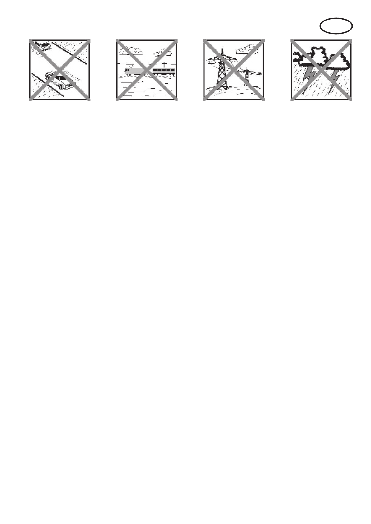
I
Rischi residui
Anche se il modello viene messo in funzione secondo le norme e tenendo conto di tutti gli aspetti di sicurezza, sussiste
sempre un determinato rischio residuo.
Quindi è obbligatorio stipulare un’assicurazione di responsabilità civile. Nel caso foste socio di un’associazione o
federazione, potete stipulare l’assicurazione anche in questa istituzione. Fare attenzione ad avere una protezione assi-
curativa sufciente (aeromodello con motorizzazione). Mantenere i modelli e il radiocomando sempre in perfetto stato.
I seguenti pericoli possono vericarsi in relazione alla costruzione e all’esecuzione del modello:
Lesioni dovute all’elica: appena il pacco batteria è collegato, tenere libera la zona dell’elica. Osservare anche che
gli oggetti di fronte all’elica possono essere aspirati o che gli oggetti dietro possono essere spinti via. Il modello
si può mettere in moto. Quindi orientarlo sempre in modo che nel caso di un avvio involontario del motore non si
possa muovere in direzione di altre persone. Durante le regolazioni in cui il motore è in funzione o può mettersi
in funzione, il modello deve sempre essere tenuto da un aiutante.
Precipitazione dovuto ad errore di comando: Può succedere anche al miglior pilota, quindi far volare il modello
solo in ambiente sicuro: un terreno omologato per aeromodelli è una relativa sicurezza sono indispensabili.
Precipitazione dovuta ad errore tecnico o danni dovuti al trasporto o danni precedenti non conosciuti. È obbli-
gatorio controllare attentamente il modello prima di ogni messa in volo. Ma bisogna sempre tenere conto che si
può vericare un guasto del materiale. Non fare mai volare il modello in luoghi in cui si possono causare lesioni
agli altri.
Rispettare i limiti di funzionamento. Un volo estremamente duro indebolisce la struttura e può o comportare un
guasto improvviso del materiale, o la precipitazione del modello durante voli successivi dovuta a danni successivi „latenti“.
Pericolo d’incendio dovuto a malfunzionamento dell’elettronica. Conservare i pacchi batteria in modo sicuro, ris-
pettare le avvertenze di sicurezza dei componenti elettronici nel modello, del pacco batteria e del caricabatteria,
proteggere l’elettronica dall’acqua. Fare attenzione che il regolatore e il pacco batteria siano sufcientemente
raffreddati.
Le istruzioni dei nostri prodotti non devono essere riprodotte e /o pubblicate senza espressa autorizzazione
della Multiplex Modellsport GmbH & Co. KG (per iscritto) - neanche solo in parte né sotto forma di stampa né
in formato elettronico.
31
Page 32

RR FunGlider # 26 4273
Acquistate familiarità con il kit di montaggio!
Le scatole di costruzione per modelli MULTIPLEX sono soggette, in fase di costruzione, a continui controlli relativi alla
qualità del materiale. Ci aguriamo che siate soddisfatti del contenuto della scatola di costruzione. Vi preghiamo comun-
que di vericare tutti i pezzi (in base alla distinta) prima dell’uso, in quanto i componenti già utilizzati per il montaggio
sono esclusi dal diritto di sostituzione. Qualora un componente non sia a posto, siamo disposti a ripararlo o sostituirlo
dopo adeguata verica. Vogliate inviare il pezzo in oggetto in busta/pacchetto adeguatamente affrancati al nostro reparto di costruzione modelli, non dimenticando di allegare il modulo di reclamo compilato. Lavoriamo costantemente
all’ulteriore sviluppo tecnico dei nostri modelli. Ci riserviamo il diritto di effettuare in qualsiasi momento modiche al contenuto della scatola di costruzione in termini di forma, misure, tecnica, materiale e dotazione senza preavviso. Vogliate
cortesemente comprendere che i dati e le immagini di queste istruzioni non danno diritto a sporgere reclami.
Importante!
I modelli radiocomandati, in particolare gli aeromodelli, non sono giocattoli in senso tradizionale. La loro costruzione e il loro funzionamento richiedono conoscenze tecniche, un minimo di accuratezza manuale, disciplina e
consapevolezza dei rischi.
Errori e imprecisioni durante la costruzione ed il funzionamento possono causare lesioni alle persone e danni materiali.
Visto che il costruttore non ha alcuna inuenza su un assemblaggio, una manutenzione e un funzionamento corretti,
vogliamo espressamente porre l’attenzione su questi pericoli.
Avvertenza:
Il modello ha come ogni aereo, dei limiti dal punto di vista statico! Voli in picchiata e altre manovre rischiose senza
pensarci possono comportare la perdita del modello. Osservare quanto segue: in tali casi non forniamo alcuna sostituzione. Avvicinarsi con attenzione ai limiti. Il modello è previsto per la motorizzazione da noi consigliata, ma può resistere
perfettamente e senza danni ai carichi solo se assemblato in modo perfetto.
I
Il modello RR è quasi pronto al volo. Prima di terminare e di mettere in funzione il modello, leggere assolutamente le
istruzioni, le avvertenze ed i consigli. Per equipaggiare il modello sono ulteriormente necessari una ricevente ed il pac-
co batteria. Per i componenti consigliati, consultare le istruzioni e (per esempio per radio, caricabatterie, ecc.) il nostro
catalogo o il nostro sito Multiplex: www.multiplex-rc.de
Lista materiale RR
Pos. Pz.Descrizione Materiale Dimensioni
1 1 Istruzioni di montaggio
3* 1 Fusoliera preassemblata* espanso Elapor nito
5* 1 Semiala sinistra espanso Elapor nito
6* 1 Semiala destra espanso Elapor nito
7+8 1 Piano di quota espanso Elapor nito
30 50 Peso trim Sfera in metallo Ø4mm / 15g
32 1 Peso trim Sfera in metallo Ø13mm / 9 g
20 2 Velcro parte uncinata materiale plastico 25 x 60 mm
21 2 Velcro parte stoffa materiale plastico 25 x 60 mm
28 1 Chiave a brugola metallo SW 1,5
* con installati 4 servi Nano-S (UNI), inclusi tutti i rinvii, motore PERMAX BL-O 2816-0900, regolatore MUL TIcont BL-20
SD, elica inclinabile 9x6” già montata.
Elementi a radiocomando nel modello / altri accessori
Dotazione consigliata:
Ricevente MULTIPLEX a partire da RX-5 light M-LINK Codice di ord. 5 5808
oppure Ricevente RX-5 M-LINK telemetrica Codice di ord. 5 5817
In questo modo potete anche utilizzare i moduli telemetrici e dotare il Vostro modello
p.es. con il sensore variometro/altimetro e il sensore di corrente (orologio elettronico che indica il livello di carica della
batteria)!
Pacco batteria consigliato:
Pacco batteria per motorizzazione Li-BATT FX 3/1-950 (M6) Codice di ord. 15 7321
Colla:
Zacki ELAPOR ® 20g Codice di ord. 59 2727
Zacki ELAPOR ® Super liquid 10g Codice di ord. 59 2728
Caricabatteria HiTEC Multicharger X1 AC Plus, con Codice di ord. 114 118
alimentatore AC/DC 100-240V/10-18V 6,0A
32
Page 33

Nota importante
Questo modello non è in Styropor ™! Pertanto non è possibile incollare con colla vinilica, poliuretano o colla epoxy.
Queste colle aderiscono solo supercialmente e non tengono in caso di emergenza. Utilizzare unicamente colla istantanea in cianoacrilato a viscosità media, preferibilmente Zacki ELAPOR® # 59 2727, perfezionata e adattata all’espanso
ELAPOR®. Se utilizzate i prodotti Zacki-ELAPOR® potete rinunciare per lo più all’uso di kicker e attivatore. Se invece
utilizzate altre colle, e non potete rinunciare a kicker/attivatore, spruzzare questi prodotti esclusivamente all’aperto, per
ragioni di salute. Attenzione durante il lavoro con tutte le colle in cianoacrilato. Queste colle induriscono nel giro di pochi
secondi, per cui va evitato il contatto con le dita o altre parti del corpo. Per proteggere gli occhi portare assolutamente
occhiali protettivi! Tenere lontano dalla portata dei bambini! In alcuni punti è anche possibile utilizzare colla a caldo. Nelle
istruzioni, se necessario, lo indichiamo!
Come lavorare con Zacki ELAPOR®
Zacki ELAPOR® è stata sviuppata appositamente per incollare i nostri modelli in schiuma ELAPOR® .
Per effettuare l’incollaggio in modo ottimale, bisogna osservare i seguenti punti:
• Soprattutto nel caso di incollaggi di grandi superci consigliamo di far essiccare i componenti per 24 h.
• L’attivatore è da utilizzarsi esclusivamente per il ssaggio a punti. Spruzzare solo poco attivatore su un lato.
• Lasciar seccare l’attivatore per ca. 30 secondi.
• Per un incollaggio ottimale irruvidire la supercie con carta abrasiva (grana da 320).
• Una supercie inumidita con pochissima acqua accelera l‘indurimento della colla e si può quasi rinunciare all‘attivatore.
A tal scopo inumidire molto leggermente la supercie opposta alla colla con un panno umido o con una spugna umida.
Curvo - non esiste. Nel caso qualcosa venisse piegato p.es. durante il trasporto, lo si può riparare. In questo
caso ELAPOR® è simile al metallo. Ricomporre qualcosa di piegato, il materiale è leggermente elastico ma
mantiene la forma. Tutto ha però dei limiti - non esagerate!
Curvo - si che esiste! Se volete verniciare il Vostro modello, sfregare leggermente la supercie con MPX Primer
# 602700 come se voleste pulire il modello. Gli strati di vernice non devono essere in alcun caso troppo grossi o irrego-
lari , altrimenti il modello si deforma. Diventa curvo, pesante e spesso perno inutilizzabile! Vernici opache danno spesso
il miglior risultato estetico.
Consigliamo i colori del nostro assortimento di colori a spruzzo „ELAPOR® Color“ # 60 2701 - # 60 2712“ (è necessario
un pretrattamento con MULTIPrimer # 60 2700).
Dati tecnici: FunGlider
Apertura alare 1300 mm
Lunghezza complessiva 800 mm
Peso in ordine di volo a partire da 590 g
Supercie alare ca.20,5 dm² (FAI)
Carico alare a partire da 28,9 g/dm²
Funzioni RC:
Alettoni, timone di quota, direzionale, comando motore
Il baricentro si trova a 57 mm dal bordo anteriore dell‘ala. La posizione deve essere contrassegnata con una piccola
borchia sulla parte inferiore dell‘ala.
1. Prima dell‘assemblaggio
Prima dell‘assemblaggio controllare il contenuto della
scatola di montaggio.
A tal scopo sono utili le gg. 1+2 e la lista materiale.
2. Montaggio del radiocomando
Con il posizionamento dei componenti potete leggermente
influenzare la posizione corretta del baricentro. Il
bilanciamento nale avviene grazie al riempimento di sfere
di zavorra nei fori dell‘impennaggio direzionale.
La ricevente (RX) M-LINK viene ssata nello spazio libero
dietro i servi sul fondo della fusoliera. L‘antenna viene fatta
uscire dall‘apertura dell‘aria di scarico e ssata con nastro
adesivo. Sotto il regolatore viene ssato anteriormente il
pacco batteria della motorizzazione Li-BATT FX 3/1-950
con nastro adesivo alla parete laterale della fusoliera.
Mettere in ordine i cavi e ssare p.es. con colla a caldo o
nastro adesivo alla parete della fusoliera. Fig. 3
Nota: Visto che la forza adesiva del nastro adesivo tiene
meglio dell‘autoadesivo sulla superficie dell‘espanso,
consigliamo di incollare il na che con colla a caldo o Zacki
ELAPOR ®.
3. Pale dell‘elica inclinabili
Serrare le viti in modo che le pale dell‘elica non presentino
alcun gioco, ma che si possana ra reclinare leggermente
indietro.
Fig. 4
33
Page 34

4. Primo giro di prova del motore
Nota: Inserire la spina di raccordo del pacco batteria della
motorizzazione / del regolatore solo quando la vostra radio
è accesa e siete sicuri che l‘elemento di comando per il
controllo del motore è su „OFF“!
In collegamento con il vostro radiocomando e il pacco
batteria della motorizzazione controllare il senso di
rotazione (ancora senza elica). Guardando in direzione
di volo, l‘albero motore deve girare in senso orario (verso
destra). 9el caso non fosse ce dei tre cavi di collegamento
del motore.
5. Servi alettoni
Le lever del servo girate di 2 denti in avanti rispetto
al carter (speculare). Questa regolazione consente la
differenziazione meccanica degli alettoni, quando non è più
possibile in modo elettronico (mixer) con la vostra radio. La
differenziazione è quindi adattata meccanicamente in modo
che le escursioni del timone verso l’alto siano maggiori che
verso il basso.
Fig. 5
6. Inserire le superci alari nella fusoliera
Inserire quindi le superci alari nella fusoliera.
Per smontare le superci alari tirare la linguetta con un dito
in avanti verso il bordo anteriore dell‘ala, sino a quando la
dentatura è aperta.
Fig. 6
8. Come regolare le escursioni del timone (valori
indicativo!)
Per ottenere un comando equilibrato del modello, si deve
regolare correttamente la grandezza delle escursioni del
timone. Le escursioni vengono misurate ogni volta nel punto
più basso del timone.
Alettoni: 12 / 6 mm +/Elevatore: 10 / 10 mm +/Direzionale: 15 / 15 mm +/-
Spoiler: 14 mm (Alettoni verso l‘alto)
Compensatione in elevatore:
Spoiler: 3,5 mm „verso il basso“
Motore: 1 mm „verso il basso“
L‘impennaggio elevatore è su neutro, quando si vede il
grano a brugola attraverso l‘apertura laterale della fusoliera.
Prima di serrare il grano, posizionare il servo del timone di
quota esattamente su neutro!
Fig. 10
La funzione “Spoiler” permette di alzare entrambi gli alettoni
per accorciare l’atterraggio. Contemporaneamente è
necessario miscelare l’elevatore a picchiare per mantenere
il modello in una fase di volo stabile. Per usare questa
funzione devono essere presenti sulla radio i mixer
necessari. Consultare a tale proposito le istruzioni allegate
al radiocomando.
Nota: Se successivamente durante l‘uso del modello il
bloccaggio delle superci alari è troppo allentato, lo si può
nuovamente comprimere con forza per dare una tenuta
sicura al dente.
Ora montare l‘impennaggio elevatore in prova alla fusoliera.
A tal scopo avvicinare ambedue le metà dell‘impennaggio
elevatore l‘una all‘altra, in modo che si blocchino.
Fig. 7
Nota: l‘impennaggio elevatore
Per lo smontaggio premere sul punto contrassegnato con
„X“ sull‘impennaggio 8 per sbloccare il bloccaggio.
Fig. 8
Nota: Fare attenzione che l‘impennaggio possa essere
mosso con facilità. Eventualmente può rendersi necessario
schiacciare leggermente l‘espanso sul lato frontale dei
piani di coda. Ciò funziona facilmente quando la metà
dell‘impennaggio viene posizionata con la parte frontale
sullo spigolo del tavolo spostandola avanti indietro
esercitando leggera pressione.
L‘espanso può essere leggermente tagliato con un coltello.
7. Controllo del modello
Assicurarsi che il modello sia diritto che tutti i componenti
del radiocomando siano montati e collegati in modo corretto.
Controllare le regolazioni del timone, i sensi di rotazione
dei servi e la facilità di funzionamento dei meccanismi del
timone. Fare attenzione che i cavi di collegamento non
possano nire nel motore che si gira e/o leva del servo
(incollati)! Controllare nuovamente anche il senso di
rotazione del motore ora insieme all‘elica.
Fig. 9
34
Nota: con alettoni a destra, l’alettone di destra (visto in
direzione di volo) deve muoversi verso l’alto.
Per la creazione propria di colori consigliamo il nostro
assortimento di colori spray „ELAPOR® Color“ # 60 2701 - #
60 2712“ (è necessario un prettrattamento con MUL TIPrimer
# 60 2700).
Consigli per verniciare con „ELAPOR® Color“ i colori a
spruzzo sono elencati anche nel nostro Sito sotto le FAQ
(domande frequenti).
9. Bilanciare il baricentro
Con la posizione del regolatore, dell‘accumulatore di volo
e, se necessario, della zavorra aggiuntiva viene regolato il
baricentro. Questa posizione è a 57 mm dal “bordo di entrata
alare” alla fusoliera misurata verso la parte posteriore. La
posizione deve essere contrassegnata con una piccola
borchia sulla parte inferiore dell‘ala. Con l‘aiuto della dita
supportare il modello e bilanciare orizzontalmente il modello
in modo che la punta della fusoliera sia leggermente rivolta
verso il basso.
La zavorra aggiuntiva 30 / 32 viene inserita nelle camere e
coperta con l‘adesivo rotondo del decal.
Fig. 11 + 12
10. Preparativi per il primo volo
Per il primo volo è consigliabile scegliere una giornata
possibilmente priva di vento. Particolarmente indicate sono
spesso le ore serali. Con poca o nessuna esperienza di
pilotaggio, farsi aiutare da un modellista esperto. Da soli,
molto probabilmente il primo volo non avrà successo. Per
informazioni utili contattare il club modellistico di zona. Per
indirizzi contattare il vostro rivenditore.
Prima del primo volo effettuare assolutamente un test di
ricezione! Rispettare le indicazioni del costruttore del vostro
radiocomando!
Page 35

Il pacco batteria della radio e l‘accumulatore di volo devono
essere stati appena caricati secondo le prescrizioni. Prima
di accendere la radio, assicurarsi che il canale usato sia
libero, per quanto non si usi un impianto da 2,4 GHz.
Nel caso qualcosa non fosse chiaro, rinunciare in ogni caso
al decollo. Consegnare tutto l‘impianto (con pacco batteria,
cavo dell‘interruttore, servi) alla divisione di assistenza
tecnica clienti del costruttore in modo che venga controllato.
11. Primo volo …
Il modello viene avviato tenendolo in mano (sempre con-
trovento).
Durante il primo volo vi consigliamo di chiedere il supporto
di una persona esperta. Dopo aver raggiunto la quota di
sicurezza regolare i timoni tramite trim alla radio in modo
che il modello voli diritto.
Nel caso di aliante a motore si consiglia di familiarizzare a
quota sufciente con il modello, in modo da sapere come
reagisce il modello quando viene spento il motore. Simu-
lare in ogni caso atterraggi a quota sufciente, in questo
modo siete preparati quando il pacco batteria della motorizzazione è scarico.
Nella fase iniziale, soprattutto durante l’atterraggio, cercare di non prendere delle “curve troppo accentuate” e vicine
al terreno. Atterrare in modo sicuro, è sempre meglio fare
qualche passo che rischiare un atterraggio di fortuna con
il vostro modello.
12. Volo in pendio
Il volo in pendio è sicuramente il modo più piacevole per
volare un aliante. Volare portati dal vento del pendio,
un‘esperienza ineguagliabile. Il culmine è certamente il
volo in termica partendo dal pendio. Lanciare il modello,
volare fuori sopra la valle, cercare la termica, farsi portare
in quota (attenzione il modello è piccolo!), e scendere in
acrobazia, per ricominciare il gioco - questo è modellismo
alla perfezione. Grazie alla motorizzazione elettrica il
modello può essere tenuto in quota e fatto rientrare quando
le correnti ascensionali non sono più sufcienti.Quindi non si
ha il rischio che il modello si danneggi nel caso di atterraggio
fuori pista in valle.
13. Funzionamento istruttore / allievo
Grazie alle sue docili caratteristiche di volo e alla sua lunga
autonomia il FunGlider è ideale anche come aereo di
addestramento. Con lo stick radio senza li istruttore-allievo
# 4 5183, due radio MULTIPLEX e un istruttore esperto,
l‘allievo può imparare a volare proteggendo il materiale.
Dopo breve tempo l‘allievo sarà in grado di comandare
autonomamente il modello.
Tutte le radio con la tecnologia 2,4 GHz M-LINK possono
essere utilizzate come radio per allievi. Tutte le radio
MULTIPLEX con presa multifunzione DIN e funzionalità
istruttore sono adatte come radio per istruttori, a prescindere
che abbiano una dotazione 2,4 GHz M-LINK* oppure xx
Mhz. L‘istruttore e l‘allievo possono, nel caso di necessità,
essere anche distanti 20 – 30 metri l‘uno dall‘altro e non vi
è più alcun impedimento dovuto al cavo di collegamento
MULTIight. Avete la possibilità di testare in abbondanza
e in modo piuttosto realistico diversi elicotteri e aeromodelli Multiplex, prima di decidere se acquistare. Il paesaggio tridimensionale vi offre lo scenario di un tipico campo
d’aviazione di aeromodellismo. Il simulatore di volo MUL-
TIight è disponibile gratuitamente, oppure può essere
scaricato dal sito internet della nostra azienda (www.mul-
tiplex-rc.de).
Il simulatore può essere gestito mediante interfaccia con
un joystick, un gamecontroller o con una radio RC. Esso è
particolarmente confortevole per chi possiede un MULTIPLEX M-LINK, in quanto è possibile manovrare il proprio
modello al PC, senza cavi, mediante lo stick di MULTIflight.
Con MULTIight potete afnare la vostra destrezza di volo
senza fare alcun danno. Tutti i modelli hanno una condotta
di volo molto realistica, che potete sperimentare soprattutto in situazioni limite quali: stallo aerodinamico, torsione,
comportamento di caso di snap negativo e snap positivo.
15. Sicurezza
La sicurezza è la regola principale da rispettare durante
il volo con gli aeromodelli. È obbligatgorio avere una assicurazione di responsabilità civile. Nel caso siate soci di
un’associazione o club, questa assicurazione viene stipulata dall’associazione stessa.Fare attenzione ad avere
una copertura assicurativa sufciente (aeromodello con
motorizzazione). Mantenere sempre in stato perfetto i
modelli e il radiocomando. Informatevi su come caricare
correttamente
i pacchi batteria da voi utilizzati. Utilizzare tutti i dispositivi
di protezione sensati che vengono offerti. Informatevi nel
nostro catalogo principale o al nostro sito Internet
www.multiplexrc.de
Il prodotti MUL TIPLEX sono stati sviluppati da aeromodellisti esperti in base alle loro esperienze pratiche. Volare
sempre in modo responsabile! Volare a bassa quota, sopra
la testa delle persone non indica una particolare bravura,
il vero campione non lo ritiene necessario. Nell’interesse
di tutti noi si faccia presente questo fatto anche agli altri
modellisti. Volare sempre in modo da non mettere in pericolo né voi stessi né gli altri. Pensare sempre che anche il
radiocomando migliore può in ogni momento essere soggetto ad interferenze esterne. Anche anni di esperienza
pratica, priva di incidenti non è una garanzia per i prossimi
minuti di volo.
Prima di ogni avvio controllare che il pacco batteria
sia ben sso nella sua sede, inoltre controllare anche
le ali e i piani di coda. Controllare anche che tutti i ti-
moni funzionino correttamente!
Noi, il team della MULTIPLEX vi auguriamo buon divertimento e tanto successo durante l’assemblaggio e anche
dopo, durante il volo.
MULTIPLEX Modellsport GmbH & Co. KG
14. Simulatore di volo
Ecco il nostro consiglio per il divertimento di volo senza
limiti, per il quale non dovete sborsare neanche un cent
e che vi garantisce comunque suspense e un realistico
paesaggio tridimensionale.
MULTIPLEX vi offre il simulatore di volo di alta qualità
35
Page 36

Istruzioni d’uso
Tipo:
BL-O 2816-0900
#
Gmin
Numero elementi
NiXX / LiPo:
Campo di lavoro ottimale:
10 A – 14 A
Corrente max. per 15 sec.:
18 A
∅
Diametro:
Lunghezza:
31 mm
Peso:
72 g
Rend
200 W
Numero di giri max.:
Temperatura max. cassa:
Fissaggio:
∅ 19 / 16 mm / 4 x M3
PERMAX BL-2816-0900 – motore brushless a cassa rotante
! Queste istruzioni sono parte integrante del prodotto e
contengono informazioni importanti. Per questo motivo è
indispensabile conservarle con cura e, in caso di vendita
del prodotto, consegnarle all’acquirente.
1. INTRODUZIONE
I motori PERMAX sono prodotti con elevati standard qualitativi,
per soddisfare i modellisti più esigenti. Il peso ridotto, l’elevata
efficienza e coppia, con una lunga durata nel tempo, sono i punti
di forza di questi motori. PERMAX - il motore di punta per
motorizzare i tuoi modelli RC.
2. DATI TECNICI
33 3112
-1/V:
albero:
imento max.:
I motori brushless PERMAX della serie BL-O 2816 sono stati
concepiti per modelli 3D con un peso in ordine di volo fino a ca.
500 g, per m ode lli acr oba tic i fin o a ca. 800 g o Trainer fino a ca.
1300 g, come pure per alianti fino a ca. 2000 g.
3. AVVERTENZE
• Prima di mettere in funzione, leggere le istruzioni
• Prima di ogni messa in funzione, controllare che il motore e
l’elica siano fissati saldamente
• Collegare il pacco batteria al regolatore solo con
radiocomando acceso e stick di comando del motore in
posizione „MOTORE SPENTO“
• In nessun caso avviare il motore tenendolo in mano
• Quando si installa il motore, non avvitare le viti ad una
profondità maggiore di quella indicata
• Prima d’avviare il motore, allontanare eventuali oggetti leggeri
che potrebbero essere risucchiati dal l’el ic a
• Proteggere il motore da sporco e umidità
• Fare attenzione che il motore non entri in contatto con corpi
estranei
• Durante il funzionamento non sostare davanti o a lato dell’elica
in movimento
• Non superare il numero di giri massimo consentito per il
motore e l’elica
900
7 - 12 / 2S - 4S
4,0 mm
28 mm
15.000 Umin-1
65° C
• Spegnere immediatamente il motore se dovessero sorgere
delle vibrazioni. Prima di mette re nuova mente in funzione,
eliminare la causa delle vibrazioni (p.es. bilanciare l’elica)
• In nessun caso collegare i motori brushless PERMAX
direttamente all’alimentaz ion e – il motore si danneggia
irrimediabilmente
4. INFORMAZIONI
I motori brushless PERMAX necessitano di un regolatore per
motori brushless privi di sensori. Per invertire il senso di
rotazione, scollegare il pacco batteria per evitare cortocircuiti, e
invertire semplicemente due dei tre cavi che collegano il motore
al regolatore.
Non piegare eccessivamente i cavi del motore e posizionarli in
modo che siano protetti dalle vibrazioni.
Non accorciare i cavi del motore. Per installare dei connettori
diversi da quelli già montati, dissaldare i connettori.
Durante il volo, il motore ed il regolatore devono essere
raffreddati sufficientemente. Il carico max. del motore è
consentito solo per massimo 15 secondi. In nessun caso la
temperatura della cassa deve superare i 65° C.
Usare solo eliche bilanciate, per proteggere i cuscinetti ed
eliminare le vibrazioni.
5. MANUTENZIONE
I motori brushless non richiedono normalmente manutenzione.
Una manutenzione minima aumenta però di molto la loro durata
nel tempo:
Proteggere il motore, ed in particolare i cuscinetti dalla polvere e
dallo sporco. Cuscinetti sporchi si possono bloccare.
Lubrificare periodicamente i cuscinetti con olio adeguato. Non
immergere il motore in acqua o solventi.
6. CONSIGLI PER LA SCELTA DEL MOTORE
Per la scelta del motore, tenere conto del tipo di modello, del
campo d’impiego, del peso e velocità dell’aeromode llo.
Per la scelta del motore consigliamo:
• ca. 100 Watt/kg di potenza assorbita per alianti
• ca. 150 Watt/kg per modelli tipo trainer
• ca. 250 Watt/kg per modelli acrobatici
• ca. 400 Watt/kg per modelli acrobatici 3D
Tenendo conto del peso complessivo e del tipo di modello è
quindi possibile calcolare la potenza necessaria. Per ottenere la
corrente assorbita, basta dividere la potenza in entrata per la
tensione prevista. I [A] = P [W] / U [V]
Per il calcolo della tensione in entrata prevista, usare un valore
pari all’90 % della tensione nominale del pacco batteria - per un
elemento NiXX quindi 1,1 Volt, per un elemento LiPo 3,3 Volt.
Per scegliere l’elica adatta, consultare i diagrammi riportati di
seguito, prendendo come riferimento la tensione di funzionamento e l’assorbimento calcolato.
Nota: un modello acrobatico, trainer o 3D (con un volo
relativamente lento, ma potente) necessita di un’elica diversa,
rispetto a quella necessaria per un aereo che vola ad una
velocità molto elevata.
Istruzioni PERMAX 2816-0900 (14-03-28/BRAN) # 82 5881 Con riserva di errori e modifiche! MULTIPLEX
MULTIPLEX Modellsport GmbH & Co.KG • Westliche Gewerbestraße 1 • D-75015 Bretten • www.multiplex-rc.de Pagina 1/2
Page 37

Istruzioni d’uso
PERMAX BL-2816-0900 – motore brushless a cassa rotante
Per modelli che hanno un volo relativamente lento, usare eliche
con un rapporto diametro-passo (D/P) di massimo 2:1 (ca. 7“ x
4“ o 8“ x 4“).
Per modelli veloci utilizzare eliche con un D/P di massimo 1:1
(p.es. 5“ x 5“). La spinta massima si ottiene con un D/P di 2:1, la
velocità massima con un D/P di 1:1.
In nessun caso superare il numero di giri massimo consentito
per il motore e l’elica!
Esempio Motorizzazione per un modello tipo trainer con un
peso complessivo di ca. 1,0 kg, utilizzando un
Prendendo come riferimento il peso complessivo di 1,0 kg ed il
tipo di modello si ottiene una potenza in entrata di (1,0 kg x 150
Watt/kg ) ca. 150 Watt.
Presupponiamo che si voglia alimentare il modello con un pacco
batteria LiPo 3S, (90 % della tensione nominale di 3,7
V/elemento x 3 elementi ) con 9,9 Volt. La corrente
necessaria è in questo caso (150 Watt / 9,9 V ) ca. 15,1 A.
Visto che il modello ha un volo relativamente lento, sarà
necessaria un’elica con un rapporto D/P di ca. 2:1. Questo
significa che l’elica adatta sarà di ca. 11“ x 4,7.
Misurare in ogni caso il numero di giri e l’assorbimento di
corrente del motore sotto sforzo e gas al massimo. Un
assorbimento troppo elevato può provocare il surriscaldamento
del motore.
PERMAX BL-O 2816-0900
7. GARANZIA
I prodotti MULTIPLEX sono coperti da garanzia, come previsto
dalle leggi vigenti. In caso di riparazione in garanzia, rivolgersi al
rivenditore presso il quale il prodotto è stato acquistato.
Sono esclusi dalla garanzia i difetti dovuti a:
• Uso improprio (p.es. surriscaldamento), collegamento errato,
cortocircuiti
• Utilizzo di accessori non originali MULTIPLEX
• Danneggiamento volontario/involontario
• Difetti dovuti a normale usura
• Funzionamento aldifuori delle specifiche tecniche
modifiche/riparazioni non effettuate dalla MULTIPLEX o
centro assistenza autorizzato MULTIPLEX per le
riparazioni contatta il nostro centr o assiste nz a
8. CONTRASSEGNO CE
La valutazione degli apparecchi avviene secondo le
normative europee. Lei è quindi in possesso di un
apparecchio che rispetta i requisiti di costruzione e
sicurezza stabiliti dall’Unione E uropea .
La dichiarazione di conformità per l’apparecchio può essere
richiesta alla MULTIPLEX Modellsport GmbH & Co.KG
all’indirizzo riportato a fondo pagina.
9. SMALTIMENTO
Apparecchi elettrici contrassegnati con il bidone della
spazzatura depennato, non possono essere smaltiti
nella spazzatura domestica, ma devono essere
apportati ad un idoneo sistema di riciclaggio.
Nei paesi dell’UE (Unione Europea) gli apparecchi elettrici non
possono essere smaltiti nella spazzatura domestica (WEEE Waste of Electrical and Electronic Equipment, direttiva
2002/96/EG). Per lo smaltimento di un apparecchio dismesso,
servirsi dei sistemi di riciclaggio e raccolta siti nel comune di
residenza (p.es. centri di riciclaggio), dove l’apparecchio verrà
smaltito in modo idoneo e gratuito.
Con lo smaltimento adeguato degli apparecchi dismessi, si da
un contributo importante per la salvaguardia dell’ambiente!
Istruzioni PERMAX 2816-0900 (14-03-28/BRAN) # 82 5881 Con riserva di errori e modifiche! MULTIPLEX
MULTIPLEX Modellsport GmbH & Co.KG • Westliche Gewerbestraße 1 • D-75015 Bretten • www.multiplex-rc.de Pagina 2/2
Page 38

Cuaderno de seguridad para modelos de aviones MULTIPLEX
ES
El modelo NO ES UN JUGUETE en el sentido habitual de la palabra.
Con la puesta en marcha del modelo, el operador declara que conoce el contenido del manual de instrucciones, especi-
almente lo respectivo a consejos de seguridad, trabajos de mantenimiento y limitaciones de uso y carencias, pudiendo
cumplir todo lo requerido.
Este modelo no debe ser manejado por menores de 14 años. El manejo del modelo por menores queda supeditado a
ser realizado bajo la supervisión de un adulto que, según la ley , sea responsable y competente, siendo éste responsable
de la aplicación de las advertencias del MANUAL DE INSTRUCCIONES.
¡EL MODELO Y LOS ACCESORIOS CORRESPONDIENTES DEBEN QUEDAR LEJOS DEL ALCANCE DE LOS
MENORES DE 3 AÑOS! ¡LAS PEQUEÑAS PIEZAS SUELTAS DEL MODELO PUEDEN SER TRAGADAS POR LOS
MENORES DE 3 AÑOS! ¡PELIGRO DE ASFIXIA!
Al manejar el modelo deben respetarse todas las advertencias del MANUAL DE INSTRUCCIONES. Multiplex Modellsport
GmbH & Co. KG no será responsable de las pérdidas y daños de cualquier tipo que puedan ocurrir debido a un manejo
erróneo y/o indolente de este producto, incluyendo cualquiera de los accesorios necesarios para su uso. Esto incluye,
de manera directa e indirecta, pérdidas o daños con o sin intención y cualquier tipo de daños a las cosas.
Cada advertencia de seguridad de estas instrucciones debe ser observada forzosamente y contribuyen de manera directa
a un manejo seguro del modelo. Utilice su modelo con juicio y cuidado, y éste le divertirá a Usted y sus espectadores
sin ponerlos en riesgo alguno. Si maneja su modelo de manera poco responsable, éste podría producir serios daños
materiales y provocar graves heridas. Usted será el único responsable de seguir el manual de instrucciones y llevar a
la práctica las advertencias de seguridad.
Uso acorde al contrato
El modelo debe usarse exclusivamente en el ámbito del hobby . Cualquier otro uso queda expresamente prohibido. Ante
lesiones o daños de cualquier tipo causados a personas o animales, la responsabilidad recaerá exclusivamente en el
usuario del modelo y no en el fabricante.
Para utilizar el modelo deben ser utilizados, exclusivamente, los accesorios recomendados por nosotros. Lo componentes
recomendados han sido probados y adaptados para garantizar el funcionamiento seguro del modelo. Si se modica el
modelo o se usan componentes distintos, ni el fabricante ni el distribuidor podrán ser responsabilizados.
Para mantener al mínimo el riesgo al utilizar el modelo, tenga en cuenta los siguientes puntos:
• El modelo se maneja mediante una emisora de radio control. Ninguna emisora de radio control está libre de interferencias. Este tipo de interferencias pueden provocar que se pierda puntualmente el control de su modelo. Por
tanto, durante el manejo de su modelo debe disponer del máximo espacio posible en todas direcciones para evitar
colisiones. ¡A la menor señal de interferencias deberá dejar de usar su modelo!
• Solo debe manejar su modelo tras haber realizado y superado una completa prueba de funcionamiento y una prueba
de alcance, siguiendo las instrucciones de su emisora.
• El modelo solo debe ser pilotado en buenas condiciones de visibilidad. Nunca vuele en dirección al sol para no
quedar cegado, ni en condiciones difíciles de visibilidad.
• Un modelo no debe ser pilotado bajo los efectos del alcohol o de cualquier otro estupefaciente, o de medicación que
pueda alterar su capacidad de atención o reacción.
• Vuele solo cuando las condiciones climatológicas le permitan controlar el modelo de manera segura. T enga en cuenta
que, incluso con poco viento, se pueden formar turbulencias sobre los objetos que pueden llegar a inuir sobre el
modelo.
• Nunca vuele en lugares en los que pueda ponerse en riesgo, a Usted o a terceros, como por ejemplo: Viviendas,
tendidos eléctricos, carreteras y vías férreas.
• Nunca vuele en dirección a personas o animales. Realizar pasadas por encima de las cabezas de la gente no es
una demostración de saber hacer, sino de poner en riesgo innecesario a otras personas. Llame la atención a otros
pilotos, por el bien de todos, si se comportan de esta manera. Vuele siempre de manera que no se ponga a nadie
en peligro, ni a Usted, ni a otros. Recuerde que hasta el equipo de radio control más puntero puede verse afectado
por interferencias externas. Haber estado exento de accidentes durante años, no es una garantía para el siguiente
minuto de vuelo
38
Page 39

ES
Otros riesgos
Incluso utilizando el modelo según las normas y respetando todos los aspectos de seguridad, siempre hay un riesgo
determinado.
Por tanto, un seguro de responsabilidad civil es obligatorio. En caso de que vaya a entrar en un club o una asociación,
puede realizar la gestión del seguro por esa vía. Preste atención a los aspectos cubiertos por el seguro (aviones con
motor). Mantenga siempre los modelos y la emisora en perfecto estado.
Los siguientes riesgos pueden derivarse ya durante el montaje y la preparación del modelo:
• Heridas causadas por la hélice: Mantenga libre la zona cercana a la hélice tan pronto como conecte la batería. No
olvide retirar también cualquier objeto que pueda ser absorbido por la hélice o cualquier objeto que, quedando por
detrás, pueda ser „soplado“ por ésta. El modelo puede comenzar a moverse. Oriéntelo de tal manera que, en el caso
de ponerse en marcha inesperadamente, su trayectoria no sea en dirección a otras personas. Durante las tareas
de ajuste, en las que el motor funcione o pueda funcionar, un ayudante deberá sostener el modelo con seguridad.
• Accidentes por fallos de pilotaje: Hasta al mejor piloto le pasa: Volar en un entorno seguro, utilizar una pista autorizada y utilizar el seguro correspondiente son cosas imprescindibles.
• Accidentes debidos a fallos técnicos, daños previos o de transporte inadvertidos. La comprobación cuidadosa del
modelo antes de cada vuelo es una obligación. Siempre se debe tener en cuenta que todos los materiales sufren
de fatiga. Nunca vuele en lugares en los que se puedan producir daños a terceros.
• Respete los límites de uso. Los vuelos demasiado agresivos debilitan la estructura y pueden provocar roturas inmediatas del material, o hacer que el modelo se estrellen en un vuelo posterior por culpa de esos daños „no inmediatos“.
• Riesgo de incendio provocado por funcionamiento defectuoso de la electrónica. Conserve las baterías de manera
segura, respete las recomendaciones de seguridad de los componentes electrónicos empleados en el modelo, de
las baterías y los cargadores. Proteja la electrónica del agua. Procure la suciente ventilación del regulador y la
batería.
Las instrucciones de nuestros productos no pueden ser reproducidas ni distribuidas sin el consentimiento
expreso y por escrito de Multplex Modellsport GmbH & Co. KG, ya sea en forma impresa y/o por cualquier otro
medio electrónico.
39
Page 40

RR FunGlider # 26 4273
¡Familiarícese con su Kit!
Durante la producción, los kits de MUL TIPLEX se someten a continuos controles de material. Esperamos que el contenido del kit sea de su agrado. Aun así, le rogamos, que compruebe que todas las piezas (según la lista de componen-
tes) están incluidas antes de empezar a montar, ya que cualquier pieza que haya sido manipulada no podrá cambiarse.
En caso de que en alguna ocasión una pieza esté defectuosa, estaremos encantados de corregir el defecto o remplazar
la pieza una vez realizadas las comprobaciones pertinentes. Por favor, envíe la pieza a nuestro Servicio Técnico, con el
franqueo suciente, incluyendo sin falta la hoja (formulario) de reclamación debidamente cumplimentada. Trabajamos
constantemente en la evolución técnica de nuestros modelos. Nos reservamos el derecho de modicar el contenido del
kit de construcción, tanto en su forma como en su tamaño, técnica, material o equipamiento en cualquier momento y sin
previo aviso. Les rogamos que comprendan, que no se puedan hacer reclamaciones basándose en los datos, textos o
imágenes, de este manual.
¡Atención!
Los modelos radio controlados, especialmente los aviones, no son juguetes en el sentido habitual de la palab-
ra. Su montaje y manejo requieren de conocimientos técnicos, cuidado, esmero y habilidad manual, así como
disciplina y responsabilidad.
Errores o descuidos durante la construcción y su posterior vuelo pueden conllevar a daños personales y materiales.
Dado que el fabricante no tiene ninguna inuencia sobre la correcta construcción, cuidado y uso, advertimos especialmente acerca de estos peligros.
Aviso:
¡El modelo tiene, al igual que cualquier otro avión, sus propios límites! Los picados o las maniobras sin sentido pueden
acabar con el modelo. Tenga en cuenta: En estos casos no le ofreceremos ningún sustituto. Por tanto, sea muy cuidadoso a la hora de explorar sus límites. El modelo está diseñado para el propulsor que le recomendamos, solo de este
modo se podrá montar sin esfuerzo y soportar las cargas sin daños.
ES
El modelo RR está premontado y casi listo para volar. Antes de terminar y de volarlo, lea detenidamente las instrucciones de montaje y siga sin falta las advertencias y los consejos acerca de la seguridad.
Para completar el modelo y poder volar, solo necesita un receptor y una
batería para el motor. Por favor, consulte el manual de instrucciones para ver los productos que nosotros le recomendamos y nuestro catalogo actual o la página web de Multiplex en www.multiplex-rc.de para la emisora, el cargador, etc.
Lista de piezas
Nº Cant. Denominación Material Medidas
1 1 Instrucciones de montaje
3* 1 Fuselaje premontado* Elapor espumado Pieza terminada
5* 1 Ala izquierda Elapor espumado Pieza terminada
6* 1 Ala derecha Elapor espumado Pieza terminada
7+8 1 Cola Elapor espumado Pieza terminada
30 50 Lastre Bola metálica Ø4mm / 15g
32 1 Lastre Bola metálica Ø13mm / 9 g
20 2 Velcro lado ganchos Plástico 25 x 60 mm
21 2 Velcro lado velours Plástico 25 x 60 mm
28 1 Llave hexagonal Metal SW
* con 4 servos Nano-S (UNI) montados incl. articulación completa de los timones, motor PERMAX BL-O 2816-0900,
regulador MULTIcont BL-20 SD, hélice plegable 9x6” montada.
1. Elementos RC en el modelo / Otros accesorios
Equipo recomendado:
Receptor MULTIPLEX, a partir de RX-5 light M-LINK Referencia 5 5808
o Receptor RX-5 M-LINK compatible con telemetría Referencia 5 5817
¡De este modo podrá usar también el módulo de telemetría y , por ejemplo, equipar su modelo con el altímetro/variómetro
y el sensor de corriente (aguja electrónica del depósito)!
Baterías recomendadas
Batería principal Li-BATT BX 3/1-950 (M6) Referencia 15 7321
Pegamento:
Zacki ELAPOR ® 20gr. Referencia 59 2727
Zacki ELAPOR ® Super liquid 10gr. Referencia 59 2728
Cargador HiTEC Multicharger X1 AC Plus, con Referencia 114 118
fuente de alimentación AC/DC 100-240V/10-18V 6,0A
40
Page 41

Aviso importante:
¡Este modelo no es de Styropor ™! Por tanto, no debe usar cola blanca, poliuretano o Epoxy para las uniones.
Estos pegamentos solo producen una unión supercial y que se despega fácilmente. Utilice exclusivamente pegamen-
tos con base de cianocrilato de viscosidad media, preferentemente Zacki -ELAPOR® # 59 2727, que está optimizado
para las partículas de ELAPOR® y un pegamento instantáneo compatible. Al utilizar Zacki-ELAPOR® podría ahorrarse
el uso de activador. Sin embargo, si quiere utilizar otro pegamento y no desea prescindir del activador , deberá aplicarlos
sobre el modelo en exteriores, por razones de seguridad. Cuidado al trabajar con pegamentos a base de cianocrilato.
Estos pegamentos fraguan en cuestión de segundos, y por este motivo no deben entrar en contacto con los dedos u
otras partes del cuerpo. ¡No olvide usar gafas para proteger sus ojos!
¡Mantener lejos de los niños! En algunos puntos también puede usarse cola termo-fusible. ¡Se lo advertiremos adecu-
adamente en las instrucciones!
Trabajar con Zacki ELAPOR®
Zacki ELAPOR® ha sido desarrollado especícamente para el pegado de nuestros modelos de espuma fabricados con
ELAPOR®
Para que el pegado sea óptimo, debe respetar los siguientes puntos:
• Ante todo, al pegar grandes supercies le recomendamos dejar secar las piezas durante 24 horas.
• El activador tan solo debería usarse para jaciones puntuales. Aplique un poco de activador en uno de los lados.
• Deje que se ventile el activador durante unos 30 segundos aproximadamente.
• Para un pegado óptimo, lije suavemente la supercie con un papel de lija (grano tipo 320).
• Una supercie humedecida con muy poca agua acelera el endurecimiento del pegamento y puede evitarle la utiliza-
ción de activador. Para ello, use un paño o una esponja húmeda para aplicar el agua a la parte opuesta a la que haya
aplicado el pegamento.
¿Se dobló? – ¡No pasa nada!. En caso de que algo se haya doblado, por ejemplo durante el transporte, se puede
volver a enderezar. El ELAPOR® se comporta como si fuse metal. Si lo dobla un poco en el sentido contrario,
el material vuelve a su estado normal, manteniendo la forma. Por supuesto, todo tiene un límite - ¡No lo fuerce
demasiado”
¿Se dobló? – ¡Ya está!. Si quiere pintar su modelo, aplique una ligera capa de imprimación MPX Primer # 602700,
como si limpiase su modelo. Bajo ningún concepto debe aplicar gruesas capas o de manera irregular, podría estropear
su modelo. ¡Se torcerá, se volverá pesado y a menudo hasta frágil! Con una pintura mate conseguirá los mejores re-
sultados.
Le recomendamos las pinturas de nuestro surtido de sprays ELAPOR® Color # 60 2701 - # 60 2712 (necesita imprima-
ción con MULTIPrimer # 60 2700),
Características técnicas: FunGlider
Envergadura 1.300m.
Longitud total 800 mm.
Peso en orden de vuelo Desde 590gr.
Supercie alar Aprox. 20,5 dm2 (FAI)
Carga alar desde 28,9 gr./dm
2
Funciones RC:
Alerones, profundidad, dirección, control del motor
El centro de gravedad se encuentra a unos 57 mm. aprox. del borde de ataque del ala. La posición esta marcada con
pequeños abultamientos en la parte inferior del ala.
Nota: ¡Separe las ilustraciones del cuadernillo central!
1. Antes de comenzar el montaje
Antes de comenzar el montaje, compruebe el contenido de
su RR. Le serán muy útiles las Img. 1+2 y la lista de partes.
fuselaje. Ordene un poco el cable y use, por ejemplo, cola
caliente o cinta adhesiva para jarlo al lateral del fuselaje.
Img. 3
2. Instalación del equipo RC
Con la ubicación de los componentes se consigue ubicar
el centro de gravedad en su lugar correcto. El equilibrado
nal se logra aplicando bolas de lastre en los agujeros del
estabilizador vertical.
El receptor (RX) M-LINK se ja en la zona libre en el su-
elo del fuselaje, tras los servos. La antena se pasa por la
abertura de ventilación y se ja con cinta adhesiva. Bajo el
regulador, en la parte delantera, se ja la batería principal
Li-BATT FX 3/1 950 usando velcro en la pared lateral del
Nota: Ya que el adhesivo del velcro no es lo mejor para
una supercie de espuma, le recomendamos que aplique
además de éste un poco de cola caliente o Zacki ELAPOR®.
3. Palas de la hélice
Apriete el tornillo hasta que las palas de la hélice no presenten juego alguno pero sin llegar a apretarlo tanto que
no se plieguen fácilmente.
Img. 4
41
Page 42

4. Primera prueba del motor
Nota: ¡Conecte el conector batería/regulador, solo si su
emisora está encendida y ha comprobado que el mando
que controla el motor está en posición de apagado (OFF)!
Compruebe el correcto sentido de giro del motor usando
la batería principal y su emisora. En la dirección de vuelo,
el eje del motor debe girar en el sentido de las agujas del
reloj (hacia la derecha). Si no es el caso, intercambie dos
cables cualesquiera de los tres que van al motor.
5. Los alerones de los servos
Del servo justo 2 dientes hace adelante respecto a la carca-
sa (visto en un espejo). Este ajuste posibilita el diferencial
mecánico de los alerones, siempre 54 que su emisora no
disponga de recorrido (mezclador)
electrónico . El diferencial se ajusta mecánicamente de tal
modo que el recorrido de los timones sea mayor hacia arriba
que hacia abajo.
Img. 5
6. Adaptar las alas al fuselaje
Una ahora las alas al fuselaje. Para desmontar las alas,
use un dedo para empujar la lengüeta hacia adelante
desde el borde de ataque del ala hasta que el engranaje
quede abierto.
Img. 6
Nota: Más tarde, al utilizar el modelo, puede que el bloqueo
de las alas quede suelto y puede mejorarse presionando
rmemente para conseguir un mejor apriete con un diente
más.
A modo de prueba, monte el estabilizador horizontal en el
fuselaje. Para ello, deslice ambas mitades del estabilizador
horizontal hasta que éstas se bloqueen.
Img. 7
Nota: Los estabilizadores,
Para desmontarlos, presione sobre la posición marcada con
„X“ en el estabilizador 8 para soltar el bloqueo.
Img. 8
Nota:
Compruebe que el estabilizador pueda moverse con
facilidad. Puede que sea necesario presionar ligeramente la
espuma de la parte frontal del estabilizador. Esto funciona
mejor colocando las mitades del estabilizador con la parte
frontal sobre el canto de la mesa, deslizándola hacia atrás
y delante mientas se realiza presión, También puede usar
una cuchilla para recortar un mínimo de espuma.
7. Control del modelo
Asegúrese de que el modelo está equilibrado y todos
los componentes de radio control están bien montados y
conectados. Compruebe el ajuste de los timones, el sentido de giro de los servos y la facilidad de movimiento de la
mecánica de los timones. Asegúrese de que los cables de
conexión no puedan ser alcanzados por el motor al girar o
por los brazos de los servos (¡Fíjelos!) Vuelva a comprobar una vez el sentido de giro del motor, pero ahora con
la hélice.
Img. 9
8. Recorridos de los timones (¡Valores indicativos!):
Para poder conseguir una maniobrabilidad adecuada del
modelo, se han de ajustar correctamente los recorridos de
las supercies de mando. Los recorridos siempre se miden
en el punto más bajo de los timones.
Alerones: 12 / 6 mm +/-
Timón de profundidad: 10 / 10 mm +/Dirección: 15 / 15 mm +/-
Spoiler: 14 mm (Alerones hacia arriba)
Compensación en profundidad:
Spoiler: 3,5 mm „abajo“
Motor: 1 mm „abajo“
El estabilizador horizontal se encuentra en posición neutra
cuando a través de la abertura lateral del fuselaje se ve el
prisionero allen. ¡Antes de apretar el prisionero, asegúrese
de que el servo de profundidad está también en neutral!
Img. 10
Para la función “Spoiler” se pueden –para acortar el aterrizaje – poner hacía arriba los dos alerones. Al mismo
tiempo se mezcla un correspondiente recorrido del timón
de profundidad para mantener el modelo estable. Para ello
se necesita una emisora con las correspondientes mezclas.
Para más información consulte el manual de instrucciones
de la emisora.
Advertencia: si se da alerón a la derecha, el alerón derecho
visto hacía la dirección de vuelo se mueve hacía arriba.
Para la decoración propia le ofrecemos nuestro surtido de
pinturas “ELAPOR® Color“ # 60 2701 - # 60 2712“ (Necesita
una imprimación con MULTIPrimer # 60 2700)
Encontrará consejos sobre pintado con sprays „ELAPOR®
Color“ en nuestra página web, bajo el apartado FAQs.
9. Equilibrar el centro de gravedad.
Mediante la posición del regulador, las baterías y, en caso
necesario, algo de lastre se ajusta el centro de gravedad.
Este se encuentra a 57 mm. del „borde del ala“ medidos
en el fuselaje hacia atrás. La posición esta marcada con
pequeños bultos en la parte inferior del ala. Sostenga el
modelo con la punta de los dedos de modo que el morro
apunte ligeramente hacia abajo.
El lastre adicional 30 / 32 se coloca en los huevos y se tapa
con los adhesivos de la lámina decorativa,
Img. 11 +12
10. Preparativos al primer vuelo
Para su primer vuelo, espere siempre a un día en el que
haga el menor viento posible. A menudo, las horas del
atardecer son el mejor momento. Si no tiene experiencia
en aeromodelismo, busque un ayudante experimentado. Lo
más normal es que si lo intenta solo, no salga „muy bien“.
Póngase en contacto con los clubes locales de aeromodelismo. Seguro que su distribuidor conoce su dirección.
Antes del primer vuelo, ¡Es imprescindible hacer una prueba
de alcance! ¡Cíñase para ello a las indicaciones del fabricante
de su emisora!
La emisora y las baterías del avión han de estar recién
y debidamente cargadas. Antes de encender la emisora,
asegúrese de que el canal a emplear está libre, a no ser
que vaya a utilizar un sistema 2,4 GHz.
Si tiene alguna duda, no despegue bajo ningún concepto.
Haga que el servicio técnico autorizado por el fabricante
42
Page 43

de su equipo de radio le revise toda la instalación (batería,
interruptor, servos).
11. El primer vuelo …
El modelo se lanza a mano (siempre en contra de la direc-
ción del viento).
En los primeros vuelos, debería procurarse la ayuda de
una persona experimentada. Una vez alcanzada la altura
de seguridad, ajuste los timones utilizando los trims de la
emisora, hasta que consiga que el modelo vuele recto y
nivelado.
Cuando vuele a una altura considerable con su modelo
motorizado, familiarícese con éste y vea como se comporta con el motor apagado. Simule en cada situación vuelos
de aproximación a mayor altura para que le sea más sencillo el aterrizar una vez se agote la batería. Al principio,
no intente describir virajes cerrados, especialmente cerca
del suelo y durante el aterrizaje. Aterrice de manera segura y sea precavido para evitar roturas al aterrizar.
12. Vuelo en ladera
El vuelo en ladera es un tipo especialmente atractivo de
vuelo con planeadores. Volar durante horas, colgados del
viento, sin ayuda de tornos, es algo que brinda las experiencias más hermosas Lo máximo es aprovechar las térmicas
de la ladera. Lanzar el modelo, ir y venir sobre el valle,
buscar térmicas, encontrarlas, subir haciendo círculos hasta
donde alcanza la vista (¡cuidado, el modelo es pequeño!),
volver a bajar el modelo haciendo acrobacias y comenzar de
nuevo el juego es aeromodelismo en su máxima expresión.
Gracias a su propulsión eléctrica el modelo puede volver a
realizar trepadas aunque no haya corrientes ascendentes.
El riesgo de dañar el modelo en un aterrizaje fuera de pista
sobre el valle queda excluido de este modo.
13. Funcionamiento profesor/alumno
El FunGlider, gracias a sus nobles cualidades de vuelo
y su gran autonomía, es un ideal para aprender a pilotar
aviones. Con el stick sin cables profesor- alumno # 4 5183,
dos emisoras MUL TIPLEX y un profesor experimentado, el
alumno puede aprender a volar protegiendo el material. En
poco tiempo, el alumno será capaz de controlar el modelo
por sí solo.
Como emisora del alumno se pueden utilizar todas las emisoras que dispongan de tecnología 2,4 GHz M-LINK. Como
emisoras de profesor son apropiadas todas las emisoras
MUL TIPLEX con conector multifunción DIN y funcionalidad
de emisora de profesor, da igual si son 2,4 GHz M-LINK* o
equipos de xx MHz. Según gustos, el profesor y el alumno
pueden separarse incluso hasta 20 - 30 metros y ya no
existen más obstáculos gracias a la ausencia de cables.
Podrá controlar el simulador utilizando un joystick, un mando de juegos o con una emisora RC mediante el interface.
Resulta especialmente cómodo para los propietarios de una
MUL TIPLEX M-LINK, quienes podrán controlar, sin cables,
su modelo desde el PC con el stick MULTIight.
Con MULTIight podrá anar su destreza en vuelo sin tener
que poner en riesgo alguna cosa. T odos los modelos tienen
un comportamiento en vuelo muy próximo a la realidad que
le permitirán probar situaciones de vuelo especiales como:
Pérdidas de alimentación, torques, corregir/evitar entradas
en pérdida.
15. Seguridad
La seguridad es el primer mandamiento del aeromodelismo.
El seguro de responsabilidad civil es algo obligatorio. En
caso de que vaya a entrar en un club o una asociación,
puede realizar la gestión del seguro por esa vía. Preste
atención a los aspectos cubiertos por el seguro (aviones
con motor).
Mantenga siempre los modelos y la emisora en perfecto
estado.
Infórmese acerca de las técnicas de carga de las baterías
que vaya a utilizar. Utilice las medidas de seguridad más
lógicas que estén disponibles. Infórmese en nuestro catálogo principal o en nuestra página Web
www.multiplexrc.de
Los productos MUL TIPLEX son el resultado práctico de la
práctica de experimentados pilotos de radio control.. ¡Vuele responsablemente! Realizar pasadas por encima de las
cabezas de la gente no es una demostración de saber
hacer, los que realmente saben no necesitan hacer eso.
Llame la atención a otros pilotos, por el bien de todos, si
se comportan de esta manera. Vuele siempre de manera
que no se ponga a nadie en peligro, ni a Usted, ni a otros. Recuerde que hasta el equipo de radio control más
puntero puede verse afectado por interferencias externas.
Haber estado exento de accidentes durante años, no es
una garantía para el siguiente minuto de vuelo.
Antes de cada despegue compruebe el correcto asiento de la batería, las alas y los estabilizadores. ¡Com-
pruebe también el funcionamiento de los timones!
Nosotros, el equipo MULTIPLEX, deseamos que disfrute
del montaje y posterior vuelo y que obtenga el mayor éxito
y satisfacción.
MULTIPLEX Modellsport GmbH & Co. KG
14. Simulador de vuelo
Aquí está nuestro truco para un diversión en vuelo sin problemas, para que no tenga que pagar ni un céntimo y , a pesar
de ello, disfrutar de unos escenarios 3D impresionantes.
MUL TIPLEX le ofrece el simulador de vuelo de altas pres-
taciones MULTIight.
Usted tiene la posibilidad de probar distintos modelos de
helicópteros y aviones MULTIPLEX de manera completa
y realista antes de decidir su compra.
Los escenarios 3D le muestran las escenas de un típico
campo de vuelo.
El simulador de vuelo MULTIight está a su disposición, sin
coste, como descarga desde el sitio Web de MULTIPLEX
(www.multiplex-rc.de)
43
Page 44

Manual de instrucciones
Modelo:
BL-O 2816-0900
#
33 3112
Rpms/V
900
Elementos
NiXX / LiPo:
Rango óptimo
de trabajo:
Corriente máx. durante 15 seg.
∅
Diámetro:
28 mm
Longitud:
31 mm
Peso:
Pote
Revoluciones máximas:
Temperatura máx. de la carcasa:
Fijación:
∅
PERMAX BL-O 2816-0900 – motor sin escobillas de carcassa rotatoria
! Estas instrucciones forman parte del producto.
Contienen información muy importante y recomendaciones
de seguridad. Téngalas siempre al alcance de la mano y
entréguelas si vende el producto a un tercero.
1. INTRODUCCIÓN
Los motores sin escobillas PERMAX se diseñan con la mayor
precisión, para satisfacer las más altas exigencias de calidad de
los modelistas. Optimizados en peso, de gran eficiencia, alto par
y extrema longevidad, los motores sin escobillas PERMAX son
la elección correcta para propulsar modelos RC.
2. DATOS TÉCNICOS
7 - 14 / 2S - 4S
10 A – 14 A
18 A
del eje:
ncia máxima:
El motor sin escobillas PERMAX BL-O 2816-0900 se han
concebido para ser usados con modelos 3D de hasta 500 gr. de
peso en orden de vuelo, acrobáticos de hasta 800 gr.,
entrenadores de hasta 1300 gr. y veleros de hasta 2000 gr.
3. CONSEJOS DE SEGURIDAD
• Lea las instrucciones antes de ponerlo en marcha
• Antes de cada uso debe comprobar que tanto la hélice como
el motor están bien sujetos.
• Conecte la batería al regulador solo si ha encendido
previamente el equipo de radio y comprobado que el mando
asignado al motor está en posición “OFF”.
• Nunca haga funcionar el motor en su mano.
• Respete la profundidad de apriete máxim a permitida al instalar
el motor.
• Antes de conectar el motor, debe retirar todos los posibles
obstáculos que estén en la zona de giro de la hélice y que
puedan ser absorbidos.
• Proteja el motor de la suciedad y humedad.
• Asegúrese de que ningún cuerpo extraño pueda caer en el
motor.
• Mientras esté funcionando el motor, no se coloque delante ni
en la zona de giro de la hélice.
• No sobrepase el número máximo de revoluciones ni del motor
ni de la hélice.
4 mm
72 g
200 W
15.000 Umin-1
65° C
19 / 16 mm / 4 x M3
• Detenga el motor tan pronto como aparezcan vibraciones:
antes de intentar volverlo a arrancar deberá aclarar el motivo
de su aparición y solucionarlo, p.ej., equilibrando la hélice.
• Nunca conecte un motor sin escobillas PERMAX directamente
a la batería o fuente de alimentación ya que se estropeará.
4. NOTAS SOBRE SU FUNCIONAMIENTO
Los motores PERMAX requieren un regulador sin sensores para
motores sin escobillas. Si el motor girase en sentido contrario al
deseado, intercambie la conexión de dos de los tres cables del
motor, desconectando la batería para evitar cortocircuitos.
No fuerce los cables del motor, ni los doble demasiado, y evite
que vibren.
No acorte los cables de conexión del lado del motor, desuelde
los conectores si desea utilizar un tipo distinto.
Procure la mejor ventilación posible del motor y regulador
durante el vuelo. La carga máxima del motor solo se soporta
durante un corto espacio de tiempo, máximo 15 segundos. En
ningún momento la temperatura de la carcasa debe superar los
65º C.
Para cuidar de sus rodamientos y evitar las vibraciones, utilice
siempre hélices que estén bien equilibradas.
5. NOTAS SOBRE EL MANTENIMIENTO
Los motores sin escobillas apenas requieren mantenimiento.
Una menor carga de trabajo implica una mayor vida útil:
Proteja su motor de la suciedad y el polvo, especialmente los
rodamientos. Unos rodamientos sucios pueden agarrotarse.
Aplique regularmente un poco de aceite en los rodamientos. No
sumerja el motor en agua o disolventes.
6. CONSEJOS PARA ELEGIR MOTOR
La elección del motor y la configuración de la hélice ha de
hacerse dependiendo del tipo de modelo, o del tipo de vuelo, el
peso total y la velocidad de vuelo del modelo.
Como base para elegir los componentes le recomendamos:
• Aprox. 100 Vatios/Kilo de potencia para un velero.
• Aprox. 150 Vatios/Kilo para un entrenador
• Aprox. 250 Vatios/Kilo para un modelo acrobático
• Aprox. 400 Vatios/Kilo para un modelo acrobático/3D
Dependiendo del peso total y el tipo del modelo se puede
calcular la potencia necesaria. Se puede calcular el consumo
dividiendo la potencia absorbida por la tensión de la
alimentación. I [A] = P [W] / V [V]
Como punto de partida se ha de tomar como voltaje o tensión
de alimentación el 90% de la tensión nominal de la batería, para
un elemento de níquel 1,1 voltio, para uno LiPo 3,3 V.
Como orientación para la elección de la hélice apropiada puede
consultar los siguientes esquemas. El tamaño de la hélice
influirá directamente en el consumo y depende del voltaje de
alimentación.
Debe tener en cuenta que un modelo acrobático o entrenador a
uno para vuelo 3D (que vuelan relativamente más lentos pero
con un mayor empuje) necesitará una hélice totalmente distinta
a un modelo que deba volar más veloz.
Instrucciones PERMAX BL-O 2816-0900 (14-03-14/BRA N ) # 82 5881 ¡S alv o erro r, omi sión o modificación técnica ! MULTIPLEX
MULTIPLEX Modellsport GmbH & Co.KG • Westliche Gewerbestraße 1 • D-75015 Bretten • www.multiplex-rc.de Página 1/2
Page 45

Manual de instrucciones
PERMAX BL-O 2816-0900 – motor sin escobillas de carcassa rotatoria
En los modelos relativamente más lentos, generalmente, son
apropiadas las hélices con una relación diámetro / paso (D/P)
de hasta 2:1 (más o menos una 7” x 4” o 8” x 4”).
Los aviones que han sido diseñados para obtener las mayores
velocidades necesitan una hélice con una relación de hasta 1:1
(Por ejemplo, 5” x 5”). Alcanzará el mayor empuje estático con
una relación de 2:1, y la mayor velocidad con una relación de
1:1.
¡No olvide comprobar que el equipamiento seleccionado no
supera el régimen máximo de giro de la hélice y el motor!
Ejemplo: Configuración del sistema de propulsión de un modelo
acrobático con un peso total de aprox. 1,0 Kg., y
utilizando el PERMAX BL-O 2816-0900
Con el peso de 1,0 Kg. en orden de vuelo y el tipo de modelo se
calcula que la potencia necesaria es de unos
(1,0 Kg. x 200 W/Kg.) 150 vatios.
Supongamos que desea utilizar su modelo con una batería de 3
elementos LiPo en serie (90% de la tensión nominal de 3,7
V/elemento x 3 elementos ) con 9,9 voltios. Con esta
alimentación se deduce que el consumo es de unos
(150 vatios / 9,9 voltios ) ca. 15,1 A.
Ya que se trata de un modelo que vuela relativamente lento,
utilice una hélice con una relación D/P de aprox. 2:1. Esto
quiere decir que necesitará una hélice de 10" x 4,7"
aproximadamente.
Aun así, mida las revoluciones y el consumo, poniendo el motor
a todo gas bajo carga. Un consumo excesivo puede dar lugar a
un calentamiento severo del motor.
7. GARANTÍA
Aplicamos para nuestros productos la garantía legalmente
establecida en cada momento. En caso necesario, diríjase al
distribuidor autorizado donde haya comprado el producto para
reclamar la garantía.
La garantía no cubrirá los posibles desperfectos ocasionados
por:
• Manejo inadecuado (p. ej. Sobrecalentamiento), conexiones
erróneas o inversión de polaridad
• Uso de accesorios no originales de MULTIPLEX
• Daños ocasionados por el usuario con y sin intención de
causarlos
• Desgaste por el uso
• Funcionamiento fuera de los márgenes técnicos
especificados
• Modificaciones / reparaciones efectuadas por otras personas
distintas a MULTIPLEX o los servicios técnicos autorizados
por MULTIPLEX Use nuestros servicios para las
reparaciones
8. DECLARACIÓN DE CONFORMIDAD CE
El dispositivo ha sido probado según las siguientes
normas armonizadas de la Unión Europea: Por tanto,
posee un producto que ha sido diseñado para cumplir
con las regulaciones respecto la operatoria segura de
dispositivos de la Unión Europea.
Si lo necesita, puede solicitar esta declaración de conformidad a
MULTIPLEX Modellsport GmbH & Co.KG.
9. NOTAS SOBR E EL RECICLADO
Los dispositivos electrónicos señalizados con una
papelera bajo una cruz, no deben ser arrojados a la
basura normal, sino que se han de depositar en un
contenedor para su reciclaje.
En los países de la UE (Unión Europea) los dispositivos
eléctricos-electrónicos no deben ser eliminados arrojándolos en
el cubo de la basura doméstica. (WEEE - Es el acrónimo de
Reciclado de equipos eléctricos y electrónicos en inglés.
Directiva CE/96/2002). Seguro que dispone en su comunidad, o
en su población, de un punto de reciclado donde depositar estos
dispositivos cuando no le sean útiles. Todos los dispositivos
serán recogidos gratuitamente y reciclados o eliminados de
manera acorde a la normativa.
¡Con la entrega para el reciclado de sus antiguos aparatos,
contribuirá enormemente al cuidado del medio ambiente!
Instrucciones PERMAX BL-O 2816-0900 (14-03-14/BRA N ) # 82 5881 ¡S alv o erro r, omi sión o modificación técnica ! MULTIPLEX
MULTIPLEX Modellsport GmbH & Co.KG • Westliche Gewerbestraße 1 • D-75015 Bretten • www.multiplex-rc.de Página 2/2
Page 46

111
48
49
7, 8
Tailplane L.H./ R.H.
Connector with axis (elevator)
Connector with tting ( elevator)
111221112
909192939496979899
Propeller driver
Spinner
Driver with clamping cone Ø 4mm
Self-locking nut M3
Head screw M3x18mm
Nut M6
1
Washer M6
Tooth lock washer M6
Screw M2,2x6,5mm
1
1
1
1
1
1
1
1
1
1
1
Remote control SMART SX (1+3)
Remote control SMART SX (2+4)
Transmitter COCKPIT SX M-LINK classic
Transmitter COCKPIT SX M-LINK elegance
Transmitter COCKPITSXM-LINK action
Artikel-Nr. Bezeichnung Designation Lfd. Stück
# 26 4273
Höhenleitwerk links, rechts
HLW Steckung mit Achse
HLW Steckung mit Arretierung
# 22 4288 Höhenleitwerkssatz Tailplane set
21221121112501121121111111
9
3, 4
Fuselage shell L.H./R.H.
Fin
Spinner, Blatthalter, Mitnehmer Propeller-driver-spinner set
Propellermitnehmer (grau)
Spinner (grau)
Mitnehmer mit Spannkonus Ø 4mm
Stoppmutter M3
Zylinderschraube M3x18mm
Mutter M6
U-Scheibe M6
Zahnscheibe M6
Schraube M2,2x6,5mm
# 22 4279 Rumfpdeckel (grau) Fuselage decking (grey) 41 1
# 73 3492 Klappluftschraubenblatt 9x6“ Folding propeller blade 9x6“ 95 2
20212223242526272930323334404243464750636461626065
Velcro tape, hook 25x60mm
Velcro tape, loop 25x60mm
Control surface horn „Twin“
Swivel barrrel Ø 6x8mm
(# 33 2337) 1 St.
# 73 3509
Allen-head grubscrew M3x3mm
(# 68 2676) 10 St.
Swivel pushrod connector
Washer M2
Nut M2
Countersunk screw M2x10mm
Trim ballast Ø 4mm
(# 68 2651) 50 St.
Trim ballast Ø 13mm
Spar in-ll-piece
Cable holder
Fuselage frame (grey)
# 33 3112 Motor PERMAX BL-O 2816-0900 Motor PERMAX BL-O 2816-0900
Fuselage cover with motormount (grey)
# 7 2232 Regler MULTIcont BL-20 SD Controller MULTIcont BL-20 SD 1
# 15 7321 Akku Li-BATT FX 3/1-950 (M6) Battery Li-BATT FX 3/1-950 (M6)
# 5 5817 Empfänger RX-5 M-LINK Receiver RX-5 M-LINK
# 6 5120 x4 Servo Nano-S Servo Nano-S
# 6 5119 x4 Servo Nano Pro MG Servo Nano Pro MG
1
Servoframe „Nano“ upright
Bearing housing (elevator)
Bearing cover (elevator)
Bell crank (elevator)
Bowdentube elevator
Bowdentube rudder
Pre-formed pushrod, elevator Ø 0.8x535mm
Pre-formed pushrod, rudder Ø 0.8x565mm
Fuselage reinforcement tube
# 33 2130 Ersatzwelle Ø 4x45mm Spare shaft Ø 4x45mm
# 8 2523 MULTIcharger L-703 EQU Multicharger L-703 EQU
# 1 5300 Fernsteuerung SMART SX (1+3)
# 1 5301 Fernsteuerung SMART SX (2+4)
# 4 5130 Sender COCKPIT SX M-LINK classic
# 4 5131 Sender COCKPIT SX M-LINK elegance
22221222211
1
GRP rod
2223243133
5, 6
Wing panel L.H./R.H.
Control surface horn „Twin“
Swivel barrrel Ø 6x8mm
35
Allen-head grubscrew M3x3mm
Screw M2,2x6,5mm
Spar in-ll-piece
Pre-formed aileron pushrod
# 4 5132 Sender COCKPIT SX M-LINK action
2
384445
36, 37
Servo cover L.H:/ R.H.
60
Servo cover sticker
Wing joiner
Wing catcher
Fuselage reinforcement tube
Dekorbogen Funglider Decal Funglider 2 1
Rumpfhälften links, rechts
Seitenleitwerk
Klettband Pilzkopf 25x60mm
Rumpfsatz Fuselage set
Artikel-Nr. Bezeichnung Designation Lfd. Stück
# 72 4801
Zubehör / Accessories:
# 22 4285
Klettband Velours 25x60mm
(# 68 3112) 5 St.
(# 68 3112) 5 St.
Ruderhorn „Twin“
Kardanbolzen Ø 6x8mm
Inbus-Gewindestift M3x3mm
Gestängeanschluss Ø 6mm
U-Scheibe M2
Mutter M2
Senkschraube M2x10mm
Trimmgewicht Ø 4mm
(# 70 3457) 2 St.
(# 70 3457) 2 St.
(# 70 3457) 2 St.
(# 70 3455) 2 St.
(# 70 3455) 2 St.
(# 70 3455) 2 St.
Trimmgewicht Ø 13mm
Holmfüllstück
Kabelhalter
Rumpfrahmen (grau)
Rumpfverkleidung mit Motorspant (grau)
Servorahmen „Nano“ stehend
HLW Lagergehäuse
HLW Lagerdeckel
(# 8 5086)
HLW Hebel
Bowdenzugrohr HR
Bowdenzugrohr SR
Stahldraht für HR m. Z. Ø 0.8x535mm
Stahldraht für SR m. Z. Ø 0.8x565mm
Tragächensatz Wings set
Rumpf-Verstärkungsrohr
GFK-Stab Ø1,3x650mm
# 22 4275
Tragäche links, rechts
Ruderhorn „Twin“
Kardanbolzen Ø 6x8mm
Inbus-Gewindestift M3x3mm
Schraube M2,2x6,5mm
Holmfüllstück
Querrudergestänge m.Z.
Servohutze links, rechts
(# 70 3457) 2 St.
(# 70 3457) 2 St.
(# 70 3457) 2 St.
(# 68 2651) 50 St.
Aufkleber Servoabdeckung
Holmverbinder
Flächenarretierung
Holm Tragäche
(# 82 6504) 2St.
Page 47

(# 70 3455) 2 St.
Mutter M2
Nut
Ecrou
# 22 4275
Tragächen/ Wings/ Ailes
Rumpfrahmen (grau)
Fuselage frame (grey)
Carénage de fuselage (gris)
Rumpfverkleidung mit Motorspant (grau)
Fuselage cover with motormount (grey)
40
42
Ruderhorn „Twin“
Control surface horn „Twin“
Guignol
Swivel barrel
Rotule de xation
(# 70 3457) 2 St.
Tragächen links, rechts
Wing panel L.H./R.H.
Ailes gauche, droite
x2
5, 6
Carénage de fuselage (gris) avec pare-feu
22
Servorahmen „Nano“ stehend
Servo mount „Nano“ , upright
Cadre servo ‘’Nano’’ vertical
(# 8 5086)
x2
43
Kardanbolzen Ø 6x8mm
(# 70 3457) 2 St.
23
x2
x2
HLW Lagerdeckel
HLW Lagergehäuse
46
Bearing cover (elevator)
Bearing housing (elevator)
Compartiment pour levier de renvoie
47
27
(# 70 3457) 2 St.
Inbus-Gewindestift M3x3mm
Allen-head grubscrew
Vis six pans creux
U-Scheibe M2
Washer
Rondelle
(# 70 3455) 2 St.
x2
HLW Hebel
Bell crank
Levier profondeur
50
26
Rumpf-Verstärkungsrohr
Fuselage reinforcement tube
60
24
Couvercle pour compartiment levier
Holmfüllstück
Spar in-ll piece
(# 68 2651) 50 St.
Schraube M2,2x6,5mm
Screw
31
Tube de renfort fuselage
Stahldraht für HR m. Z. Ø 0,8x535mm
Pièce de remplissage de tube
Vis
x2
33
Pre-formed pushrod, elevator
Tringle pour profondeur avec embout en Z.
61
Aufkleber Servoabdeckung
Servo cover sticker
Servohutze links, rechts
Servocover L.H./R.H.
Couvercle de servo gauche, droite
Querrudergestänge m. Z. Ø 1x70mm
Pre-formed aileron pushrod
Tringle pour aileron avec embout Z.
35
36,37
x2
Bowdenzugrohr HR
Bowdentube elevator
63
Pre-formed pushrod, rudder
Tringle pour dérive avec embout en Z.
Stahldraht für SR m. Z. Ø 0,8x565mm
Autocollant de compartiment servo
x2
38
Bowdenzugrohr SR
Gaine de tringle
Bowdentube rudder
64
62
Holmverbinder
Wing joiner
Clé d’aile
Flächenarretierung
44
Gaine de dérive
45
# 15 7321
Akku Li-BATT FX 3/1-950 (M6)/
Battery/ Accu
Wing catcher
Système de fixation d’aile
Holmrohr
Spar tube
Tube de clé d´aile
x2
60
# 22 4285
9
Rumpf/ Fuselage/ Fuselage
3, 4
x2
Seitenleitwerk
Fin
Dérive
(# 68 3112) 5 St.
Klettband Velours 25x60mm
21
x3
Rumpfhälften links/ rechts
(# 68 3112) 5 St.
Fuselage shell L.H./R.H.
Moitié de fuselage gauche, droite
Klettband Pilzkopf 25x60mm
20
x3
Kardanbolzen Ø 6x8mm
(# 70 3457) 2 St.
Velcro tape, loop
Bande Velcro côté velours
23
Ruderhorn „Twin“
Control surface horn „Twin“
(# 70 3457) 2 St.
Velcro tape, hook
Bande Velcro côté crochets
22
Swivel barrel
Rotule de xation
(# 70 3455) 2 St.
Gestängeanschluss Ø 6mm
25
(# 70 3457) 2 St.
Guignol
Inbus-Gewindestift M3x3mm
24
Senkschraube M2x10mm
Countersunk screw
Swivel pushrod connector
Pièce de xation de tringle
Vis
x2
29
(# 70 3455) 2 St.
Mutter M2
Nut
Ecrou
27
Allen-head grubscrew
Vis six pans creux
U-Scheibe M2
Washer
Rondelle
(# 70 3455) 2 St.
x2
26
Holmfüllstück
Spar in-ll piece
Pièce de remplissage de tube
33
GFK-Stab Ø 1,3x650mm
65
Trimmgewicht Ø 13mm
Trimm ballast
Lest
32
Kabelhalter
Cable holder
Trimmgewicht Ø 4mm
Trimm ballast
Lest
34
30
x50
x2
# 33 3112
GRP rod
Tube bre
x2
Support de câbles
# 73 3509
Motor PERMAX BL-O 2816-0900 /
Motor/ Moteur
Spinner (grey)
Spinner (grey)
Cône (gris)
91
# 7 2232
Regler MULTIcont BL-20 SD/
Controller/ Variateur
(# 68 2676) 10 St.
Stoppmutter M3
Self-locking nut
Ecrou autobloquant
(# 68 2651) 50 St.
Schraube M2,2x6,5mm
93
x2
99
screw
x2
Zahnscheibe M6
Vis
Mutter M6
Shakeproof washer
Rondelle dentée
9796
Nut
Ecrou
98
(# 33 2337)
Mitnehmer mit Spannkonus Ø 4,0
Driver with clamping cone
92
Entraîneur avec axe de serragew
Zylinderschraube M3x18mm
Head screw
Vis tête cylindrique
U-Scheibe M6
Washer
Rondelle
x2
94
Propellermitnehmer (grau)
Propeller boss (grey)
Entraîneur d’hélice (gris)
Spinner, Blatthalter, Mitnehmer/
Propeller-driver- spinner set/ Hélice, entraîneur et cône
90
# 72 4801 Funglider
Dekorbogen/ Decal sheet/
Planche de décoration
2
# 22 4288
Höhenleitwerkssatz/
Tailplane Set/
Kit de profondeur
7, 8
HLW Steckung mit Achse
Profondeur
48
Höhenleitwerk L+R
Elevator L.H./ R.H.
HLW Steckung mit Arretierung
Connector with fitting (elevator)
Connector with axis (elevator)
Fixation profondeur avec axe
Fixation profondeur avec axe
49
grau
grey
gris
41
# 22 4279
Rumpfdeckel/ Fuselage decking/
Carénage de fuselage
9x6“
1 pair
1 paire
95
1 Paar
# 73 3492
Klappluftschraubenblatt/
Folding propeller blade/
Pales d`hélice repliable
Page 48

Anleitung FunGlider # 94 4800 (20141006 BEDO) Irrtum und Änderungen vorbehalten © MULTIPLEX 2015
MUL TIPLEX Modellsport GmbH & Co.KG W estliche Gewerbestr. 1 D-75015 Bretten-Gölshausen www.multiplex-rc.
48
de
 Loading...