

Page 1

Instructions
MULTIPLEX Modellsport GmbH & Co.KG • Westliche Gewerbestraße 1 • Bretten • Germany
© MULTIPLEX 2014 • Printed in Germany
www.multiplex-rc.de
Page 2

Page 3

1. Contents
1. Contents 1
2. Introduction 5
2.1. The ROYAL SX philosophy ...................... 6
2.2. Arrangement of the instructions ............. 6
3. Safety Notes 7
3.1. General safety notes ................................. 8
3.2. Range checking ......................................... 9
4. Liability / Compensation 10
5. Guarantee 10
6. CE Conformity Declaration 10
10. Switching on, using the transmitter 22
10.1. Switching on for the first time ................ 22
10.2. Switching on “normally” ......................... 22
10.2.1. Normal OpartionsFehler! Textmarke nicht definiert.
10.2.2. RF module excl. Scanner installed 22
10.3. Switching the transmitter on with throttle-
check active............................................. 22
10.3.1. Throttle-check for fixed-wing models 22
10.3.2. 23
10.3.2. Throttle-check for model helicopters 23
10.4. Binding Procedure................................... 23
10.5. Range Checking ....................................... 23
10.6. Fast Response ON/OFF .......................... 24
10.7. The Status displays ................................. 24
10.7.1. Status display 1 (standard) 24
10.7.2. Status display 2 (flight phases) 24
10.7.3. Status display 3 (timers) 25
10.7.4. Status display 4 (system information) 25
7. Specification 11
8. The Transmitter Battery 11
8.1. Safety Notes ............................................. 11
8.2. Charging the transmitter battery ........... 11
8.3. The correct method of charging ............ 12
8.4. ROYAL SX battery management ............ 12
8.4.1. Self-discharge 12
8.4.2. Unchanged features 13
8.4.3. This is important 13
8.5. Terms used in battery charging ............. 13
8.5.1. Normal charging … 13
8.5.2. Fast charging … 13
8.5.3. Trickle charging … 14
8.6. Replacing the transmitter battery .......... 14
8.7. Transmitter battery care and storage .... 14
8.8. Recycling ................................................. 14
9. The Transmitter 15
9.1. Front face of the transmitter .................. 15
9.2. Rear face of the transmitter ................... 16
9.3. Interior of the transmitter ....................... 16
9.4. Mechanical details ................................... 17
9.4.1. Opening / closing the transmitter case 17
9.4.2. Removing / installing the RF module 17
9.4.3. Ideal Transmitter Aarial Orientation When Using the
Transmitter 18
9.4.4. Replacing the transmitter battery 18
9.4.5. Disabling the stick centring spring, activating the
ratchet / friction system 19
9.4.6. Adjusting the “hardness” of the sticks 19
9.4.7. Swivelling the stick units 19
9.4.8. Adjusting / replacing the stick tops 19
9.5. Plastic stick top with three buttons:
installation and functions ...................... 20
9.6. Digital trims .............................................. 20
9.6.1. General information 20
9.6.2. Advantages of digital trims 21
9.6.3. The cruciform digital trims 21
9.6.4. On-screen trim display 21
11. The “ROYAL SX” philosophy 25
11.1. Operating the ROYAL SX ........................ 25
11.1.1. Using the keypad 25
11.1.2. Using buttons when operating a model 26
The............................................................. 26
11.2. ROYAL SX menu structure ..................... 26
11.3. What do the sticks, sliders and switches
do? Or: Global assignments (lists) ....... 27
11.3.1. What does “Assignment” mean? 27
11.3.2. What are transmitter controls? 27
11.3.3. What are switches? 27
11.3.4. Why “global” assignments? 27
11.3.5. Which assignment lists are available? 28
11.3.6. How are the assignment lists arranged? 28
11.3.7. How are the assignment lists used? 28
11.3.8. Summary: “Global assignments” 29
11.4. Global mixer definitions .......................... 29
11.4.1. Why “global” mixer definitions? 29
11.4.2. Which global mixers are available? 29
11.4.3. Mixer names with a “+” suffix 29
11.4.4. How are the free mixers used in fixed-wing model
aircraft? 29
11.4.5. How are mixers used in helicopters? 30
11.4.6. Summary of the “free mixers” 30
11.5. Model templates ....................................... 30
11.5.1. Why are model templates needed? 30
11.5.2. What do the model templates contain? 30
11.5.3. Which model templates are available? 30
11.6. Servo configuration ................................. 30
11.7. Servo calibration ...................................... 31
11.7.1. What can be calibrated? 31
11.7.2. How is the calibration carried out? 31
11.7.3. Allocation - what’s that? 31
12. Setting up a fixed-wing model 32
12.1. The method in principle .......................... 32
12.2. Setting up the new model in the
transmitter ............................................... 32
12.2.1. Menu I, call up New model 32
12.2.2. Which model memory will be used? 32
12.2.3. Selecting the Template 32
19.11.2008 1
Page 4

ROYAL SX
12.2.4. Selecting the servo configuration (servo conf.)32
12.2.5. Selecting the stick mode 33
12.2.6. Selecting the Assignment 33
12.2.7. Confirming with OK 33
12.2.8. Entering the model name 34
Preparing the controls / switches .......... 34
12.3. 34
12.3.1. Selecting / changing the idle position for spoiler /
throttle 34
12.3.2. Changing the switch ON position 35
12.4. Preparing servos ..................................... 35
12.4.1. Checking / changing the servo assignment 35
12.4.2. Checking / changing the direction of servo rotation36
12.4.3. Calibrating servos = setting the centre and
maximum travels 36
12.5. Adjusting ailerons, and activating landing
aid (Mixer AILERON+) .............................. 37
12.6. Differential aileron travel ........................ 38
12.6.1. Activating differential 38
12.6.2. Setting the differential value 38
12.7. Adjusting elevator, activating elevator
mixers (Mixer ELEVATR+) ........................ 39
12.7.1. Spoiler to elevator = Spoiler compen-sation
(Spoiler input to ELEVATR+ mixer) 39
12.7.2. Throttle to elevator = Throttle compen-sation (Thr
-Tr input to ELEVATR+ mixer) 39
12.8. Activating inboard flaps (camber-
changing flaps) (Mixer FLAP+) ............... 39
Activating the Spoiler input in the mixer FLAP+
( 40
12.8.1. Butterfly) 40
12.8.2. Activating the Flap input in the mixer FLAP+
(camber-changing flaps) 40
12.8.3. Activating the Aileron input in the FLAP+ mixer
(aileron support by the inboard (camber-changing)
flaps) 40
12.8.4. Activating the Elevator-Tr (Ele -Tr) input in the
FLAP+ mixer (snap-flap) 41
12.9. V-tail models ............................................ 41
12.9.1. Assigning V-tail servos 41
12.9.2. Activating the mixer V-TAIL+ 41
12.9.3. 41
12.9.3. Checking / changing the direction of servo rotation41
12.9.4. Adjusting the remaining inputs 42
Working with flight phases ................. 42
12.10. 42
12.10.1. What is the purpose of switching between different
flight phases? 42
12.10.2. Default settings in the menu Flight phase 42
12.10.3. Assigning flight phase switches 42
12.10.4. Locking / unlocking flight phases 42
12.10.5. Copying flight phases 43
12.10.6. Changing flight phase names 43
12.10.7. Setting a transition time 43
12.11. Supplementary functions ....................... 44
12.11.1. D/R and Expo 44
12.11.2. Activating Combi-Switch 44
12.11.3. Motor run timer 44
13. Setting up a model helicopter 45
13.1. The method in principle .......................... 45
13.2. Setting up a New model in the transmitter45
13.2.1. Menu I, call up New model 45
13.2.2. Which model memory will be used? 45
13.2.3. Selecting the template 45
13.2.4. Selecting the servo config(uration) 45
13.2.5. Selecting the stick Mode 46
13.2.6. Selecting the Assignment 46
13.2.7. Confirming with OK 46
13.2.8. Entering the model name 47
13.3. Preparing the controls / switches .......... 47
13.3.1. Checking / changing control settings for idle /
collective pitch min. and throttle limiter min. 47
13.3.2. Changing the switch ON positions and / or the
switch assignment 48
13.4. Checking / changing the servo
Assignment .............................................. 48
13.5. Checking / adjusting the main rotor ...... 49
13.5.1. Checking / changing the direction of rotation of the
rotor head servos 49
13.5.2. Calibrating servos = setting the centre and
maximum travels 49
13.6. Checking / adjusting the tail rotor .......... 50
13.6.1. Checking / changing the direction of rotation of the
tail rotor servo 50
13.6.2. The TAIL mixer 50
Basic 51
13.6.3. Offset value 51
13.6.4. Collective pitch to tail (Revo-Mix) 51
13.6.5. Mixer Zero point 51
13.6.6. Differential yaw (rudder) travel 51
13.7. Gyro ........................................................... 51
13.7.1. Parameter Type of Gyro 52
13.7.2. Adjusting gyro suppression 52
13.8 ............................................................ 53
13.8. Throttle, and associated functions ........ 53
13.8.1. What is the meaning of the terms Limiter, Curve,
Throttle Min., Trim, DTC and Throttle cut? 53
13.8.2. Throttle for electric helicopters 54
13.8.3. Throttle for I.C. powered helicopters 54
13.9. Setting the collective pitch curve ........... 55
13.10. Working with Flight phases .................. 55
13.10.1. What is the purpose of switching between different
flight phases? 55
13.10.2. Default settings in the menu Flight phase 55
13.10.3. Assigning flight phase switches 56
13.10.4. Locking / unlocking flight phases 56
13.10.5. Copying flight phases 56
13.10.6. Changing flight phase names 56
13.10.7. Setting a transition time 57
14. Main menu ¡Setup 58
14.1. Menu Transmitter .................................. 58
If the screen area is not sufficient to display all the sub-menus,
this is indicated by means of arrows ( or ) at
the left-hand edge of the screen. In this case you
can access the start or end of the list by scrolling up
or down using the UP / DOWN buttons ( / ) or
one of the two 3-D digi-adjusters. 58
14.1.1. Parameter Sound 58
14.1.2. Parameter group Safety 58
14.1.3. Parameter group Battery 58
2
Page 5
Manual
14.1.4. Parameter group Display 59
Menu ......................................................... 59
14.2. Mixer def. .............................................. 59
14.2.1. Defining a free mixer 59
14.2.2. Method of working and options for the mixer inputs59
14.2.3. Making mixer inputs switchable 61
14.3. Menu: Assignment .................................. 61
14.3.1. Sub-menu Assign.Controls 61
14.3.2. Sub-menu Assign.Switches 62
(Proportional) transmitter controls as switches: 62
14.3.3. Special case Extra Sw. 62
14.4. Menu Training ....................................... 63
14.4.1. The ROYAL SX as Teacher transmitter 63
14.4.2. The ROYAL SX as Pupil transmitter 64
14.5. Menu User ................................................ 65
14.5.1. Parameter PIN (access code) 65
14.5.2. Parameter Language 65
Parameter Name 65
14.5.3. 65
15. Main menu ¢Control 66
15.1. Menu Control ................................. 66
15.2. Menu Control ................................. 67
15.3. Menu ¢TriggerPoint .......... 68
15.4. Control menu screen layout ................... 68
15.4.1. Parameter Trim 68
15.4.2. Parameter Step (Trim increment) 68
15.4.3. Parameter Mode (throttle trim) 69
15.4.4. Parameter D/R (Dual-Rate) 69
15.4.5. Parameter Trvl (Travel) 69
15.4.6. Parameter Expo 69
15.4.7. Parameter Fixed Value 69
15.4.8. Parameter Time 70
15.4.9. Parameter Limit 70
15.4.10. Parameter Collect. P1 ... P5 (Coll. pitch curve)70
15.4.11. Parameter Throttle P1 ... P5 (Throttle curve)70
15.4.12. Parameter Throttle Min. (idle, throttle limiter) 71
Main menu 72
16. £Mixer 72
16.1. Menu Mixer Fixed-wing models . 72
16.1.1. Combi-Sw. (Combi-Switch) 72
16.1.2. Ail.Diff. (aileron differential) 72
16.1.3. Controls Mix (transmitter control mixer) 73
16.1.4. Setting up free mixers 73
16.2.4. Rotor head (swashplate mixer) 76
17. Main menu Servo K 78
17.1. Menu Calibrate ...................................... 78
17.1.1. Sub-menus for individual servos 78
17.1.2. The procedure for calibrating a servo 79
17.2. Menu Assignment .................................... 79
17.2.1. ROYAL SX 16 only: Special features relating to
servo 11 and / or servo 12 (PPM modulation) 80
17.2.2. Non-MULTIPLEX receivers with ten channels 81
17.3. Menu Monitor .......................................... 81
Menu: Test run ........................................ 81
17.4. 81
18. Main menu Timer A 81
18.1. Slot, Sum and Interval timers: display
and reset .................................................. 81
18.2. Menu ¥Timer, Model for flight time per
season / session ..................................... 82
18.2.1. Summary Timer Model 82
18.3. Menu ¥Timer, µSlot ............................ 82
18.3.1. Example: monitoring the slot time (time limit) 82
Summary: Timer 1 µSlot 83
18.3.2. 83
18.4. Menu ¥Timer, ´Sum .............................. 83
18.4.1. Example: recording motor run time 83
18.4.2. Summary Timer 2 ´Sum 83
18.5. Menu ¥Timer, ¶¶Interval ................... 84
Example 84
18.5.1. : Monitoring motor run time per climb 84
18.5.2. Summary Timer 3 ¶¶Interval 84
18.6. Total transmitter operating time ............ 84
19. Main menu Memo I 85
19.1. Selecting a model memory ..................... 85
19.2. Copying a model memory ....................... 85
19.3. Erasing model memories ........................ 86
19.4. Managing Flight phases ....................... 86
19.4.1. Selecting flight phase names 86
19.4.2. Locking / unlocking flight phases 87
19.4.3. Copying flight phases 87
Setting the flight phase transition time 87
19.4.4. 87
19.5. Checking / changing the Properties of
the current model memory .................... 87
19.5.1. What is displayed? 87
19.5.2. What can be changed? 87
19.6. Setting up a New model ............................ 87
19.7. Menu: Modulation .................................. 88
20. Special facilities 89
16.2. Menu: Mixer Helicopters ............ 74
16.2.1. Comp. Mixer (compensation mixer) 74
16.2.2. Gyro (Gyro mixer) 75
16.2.3. TAIL (tail rotor mixer) 75
a. Basic Offset value 76
b. Collective pitch to tail (Revo-Mix) 76
c. Mixer Zero point 76
d. Differential yaw (rudder) travel 76
3
20.1. Using the 3-D digi-adjuster to alter
settings in flight ...................................... 89
20.2. PC data back-up / updating .................... 90
Using a flight ............................................ 91
20.3. simulator ................................................... 91
20.4. Error messages ........................................ 91
20.5. Accessories .............................................. 91
Page 6

ROYAL SX
20.5.1. Trainer lead 91
20.5.2. Aluminium stick top with switch or button installation and functions 91
a. Installing the stick tops 91
b. Using the stick switches 92
c. Connecting the stick button 92
d. Connecting a stick switch or second stick button 92
e. Using the second stick button 93
20.5.3. Retro-fitting switches K and / or P 93
Two-position switch 94
20.5.4. Additional accessories, replacement parts 94
21. Model templates in detail 94
21.1. Fixed-wing model aircraft ....................... 94
21.1.1. BASIC model template 95
21.1.2. ACRO model template 96
21.1.3. HOTLINER model template 97
21.1.4. DELTA model template 99
21.1.5. GLIDER model template 100
21.1.6. 4 FLAPS model template 101
21.2. Model helicopters .................................. 104
21.2.1. HELImech model template 104
21.2.2. HELIccpm model template 104
21.3. Servo configurations ............................. 105
22. Appendix: “global” lists 107
22.1. Global transmitter control and switch
assignments .......................................... 107
22.2. Pre-set mixers ........................................ 108
23. Care and maintenance 109
24. Disposal 109
25. Advice and Service 109
4
Page 7

Manual
2. Introduction
We are delighted that you have decided to purchase
the MULTIPLEX ROYAL SX radio control system.
The ROYAL SX is the result of a consistent programme
of development through the ROYAL series. The new
ROYAL SX retains many familiar and proven features
from the ROYALevo in combination with new features
suggested and requested by our large circle of users.
Transmission
M-LINK is a transmission system designed by
MULTIPLEX. It operates on the 2.4 GHz ISM band,
and exploits modern FHSS technology (FHSS = Frequency Hopping Spread Spectrum).
Automatic RF channel management:
With this system it is no longer necessary for the operator to select the RF channel manually (plug-in crystals, Synthesizer). 2.4 GHz Spread Spectrum systems
automatically divide up the frequency spectrum, and
this eliminates the need for conventional frequency
monitoring. Same-channel interference (as is possible
on the 35, 40 … MHz band) is virtually impossible.
The first time the system is used you just have to
carry out a simple binding procedure to link the transmitter to the receiver. From this moment on the receiver only responds to the signals from your specific
transmitter.
FHSS technology:
The transmitter and receiver jump from channel to
channel every few milliseconds, maintaining the same
rhythm; the data is transmitted during a fraction of this
period. The resultant brief period of channel occupation minimises signal conflicts, and suppresses interference. Even if data packets are lost on particular
channels, the constant high-speed hopping to the next
channel makes any interruptions unnoticeable to the
pilot.
Good data security / transmission security:
The enormous bandwidth available on 2.4 GHz makes
it possible to transmit much greater quantities of data
than is possible, for example on the 35 MHz band
(bandwidth on 2.4 GHz = 83.5 MHz; on 35 MHz =
1 MHz). Digital modulation in conjunction with sophisticated error-checking in the receiver guarantee outstanding data quality.
Good resistance to interference:
Typical interference sources in the model, such as
electric motors, and electronic devices such as speed
controllers, petrol engine ignition systems etc., have
an interference spectrum whose maximum frequency
is significantly below the 2.4 GHz range. It is virtually
impossible for 2.4 GHz systems to suffer interference
from such sources, and this provides a further improvement in security.
Fast, accurate transmission:
MULTIPLEX M-LINK is a digital transmission system
offering a maximum of sixteen servo channels with a
resolution of 12 bits (3872 steps). Background noise
has no effect on servo signal accuracy right up to the
limits of range. Resolution, centring precision and with
it general accuracy of control are at a con-stant high
level up to the effective limits of range. M-LINK’s digital encoding allows both HOLD and FAIL-SAFE to operate very accurately. The standard servo pulse rate
of 21 ms (16-channel mode) can be reduced to 14 ms
(12-channel mode - Fast Response) in the case of the
ROYALevo, ROYAL SX and ROYAL SX M-LINK
transmitter types.
Feedback capability / Telemetry:
The 2.4 GHz ISM band offers the possibility of transmitting data from the model back to the transmitter. If
you use a telemetry-capable receiver, the actual voltage of the receiver power supply is displayed on the
transmitter’s integral screen. If the voltage falls below
the set minimum value, an audible signal warns you
that the battery is almost flat. It is also possible to
have additional telemetry data from the model displayed on the screen, provided that appropriate sensors are installed in the model; these parameters include motor current, battery voltage, temperature, …).
Short transmitter aerial:
The short 2.4 GHz transmitter aerial is robust and
easy to handle, and it does not impinge on the pilot’s
field of vision.
Operation
Digital trim system
easily accessible cruciform trim buttons, trims specific to each flight phase, clearly arranged graphic
on-screen trim display, audible support, variable
trim increments
Voltage display and battery monitor with variable
warning threshold (battery voltage) and audible
alarm
Battery management system
Transmitter battery monitor with display of residual
charge in mAh, plus calculated display of remaining operating time in hours
Servo monitor
with graphic or numerical display, for checking
model settings
Code lock PIN (4-digit) for securing the transmitter
against unauthorised data access
Hardware
Modern, ergonomically efficient case design with
ultra-precise, individually variable, swivelling ballraced stick units for use hand-held or in a tray
Graphics-capable folding screen (132 x 64 pixels)
with variable contrast
Modern FLASH processor technology; simple up-
date via the Internet when new software versions
become available
MULTIPLEX multi-function socket fitted as stan-
dard: acts as charge socket, Trainer mode interface, PC interface (PC update, data back-up, flight
simulator)
Selective Trainer mode operations
facilities provided as standard; unique QuickSelect control assignment
5
Page 8
ROYAL SX
ROYAL SX
9
16
Channels
9
16
Model memories
28
36
Timers for total transmitter operating time and
model operating time (model-specific)
Programming
Clearly designed, efficiently structured menus for
simple programming
Optional keypad or two 3-D digi-adjusters for pro-
gramming
Clear text menu system, screen texts can be dis-
played in various national languages
Model-specific settings
Flight phase switching
With up to four flight phases for fixed-wing models
and helicopters, variable transition time
Dual-Rate and Expo, variable for each flight phase
separately
Five-point servo adjustment
Servo travel right / left, centre and two intermediate
adjustment points allow compensation for linkage
inaccuracies and mechanical travel discrepancies
Three timers (slot, sum, interval)
With variable alarm time and audible alarm
Separate timer for the model’s total operating time
Convenient model memory management
Unrestricted model names, up to sixteen characters, copy and erase functions
Comprehensive set-up and mixer facilities for
fixed-wing model aircraft and helicopters
Eight model templates cater for many different
model types and help to minimise the programming effort required
Differences between transmitter versions:
We are confident that you will rapidly learn to appreciate
your ROYAL
familiarise yourself with its facilities. These operating
instructions are intended to guide you through this
process. The system will give your endless hours of
pleasure in our mutual and fascinating hobby of model
sport.
pro
once you have taken a little time to
Yours - the MULTIPLEX team
2.1. The ROYAL SX philosophy
At the design stage of the ROYAL SX we placed particular emphasis on high-level user-friendliness, flexibility and maximum standardisation.
The user-friendly aspect results from the clearly arranged menu structure, the informative and well laidout menus and the large number of useful “little
touches” which make it easier to program and use the
transmitter.
The transmitter’s flexibility is due to a combination of
two features: the large number of facilities which are
pre-defined and ready to use, and the ability to vary
almost all of them exactly as you wish. Transmitter
controls (sticks, sliders and switches) and servos can
be assigned without restriction, and the pre-defined
mixers can be modified in any way you like.
You can create your own “standard” by fine-tuning the
pre-defined mixers and assignment lists to suit your
personal preferences and applications.
Standardisation makes it easier and more intuitive to
program the transmitter. Pre-defined model templates,
mixers and assignment lists ensure that you can set
up a new model memory with just a few buttonpresses, and it is then ready for immediate use.
Chapter “11. The ROYAL SX philosophy” describes
the background to the system and related facilities,
and is intended to help you understand the way the
transmitter works. It is therefore particularly important
to read this section.
2.2. Arrangement of the instructions
In addition to other subjects, Part 1 (Chapters 1. to
10.) contains important information on the subject of
safety !. This section also includes all the informa-
tion you need concerning the transmitter’s hardware.
Essential reading!
Part 2 (Chapter 11.) concentrates on the HOW and
WHY of the ROYAL SX’s wide-ranging software func-
tions. This background information makes it much
easier to understand the sequence of operations
when programming the transmitter.
Part 3 and Part 4 describe step by step how to pro-
gram a fixed-wing model aircraft and a model heli-
copter.
First the basic functions (aileron, elevator, rudder,
throttle / collective pitch, roll, pitch, yaw) are “brought
into play”.
After this the text explains the essential steps required
to expand and refine the model’s functions.
Part 5 contains a detailed description of all the
menus, the model templates, the default transmitter
control settings, the switch assignments and much
more.
6
Page 9
Manual
Chapter
Part 1
Introduction
Safety notes
Specification
Notes on the transmitter battery
Transmitter hardware
Switching on for the first time
2.
3.
7.
8.
9.
10.
!
!
Part 2
The “ROYAL SX” philosophy
Buttons and 3-D digi-adjusters ...
... when programming
... when operating the model
... when switching on
Global assignments
Global mixers
Model templates
11.
Part 3
Programming a fixed-wing model
Preparing the transmitter
Preparing the model
Setting up the basic functions
Supplementary functions
12.
Part 4
Programming a model helicopter
Preparing the transmitter
Preparing the model
Setting up the basic functions
Supplementary functions
13.
Part 5
Reference
All the menus in detail
Trainer mode operations
Overviews
14. - 19.
14.4. + 20.6.3.
21. + 22.
Arrangement of the instructions
3. Safety Notes
! These operating instructions are an integral
part of the product, and contain important information and safety notes. Please store them
in a safe place, and be sure to pass them on
to the new owner if you ever dispose of the
product.
! Observe the safety notes!
Read the instructions carefully!
Do not switch the system on until you have
studied these operating instructions and the
safety notes which follow (either included in
the instructions, or supplied separately).
! Warning!
Radio-controlled models are not playthings in
the usual sense of the term. The construction,
the installation of the RC system and the
method of operating the models require technical expertise, care and responsible, safetyconscious behaviour. Errors and neglect can
result in serious damage or injury. However,
since we as manufacturers have no means of
ensuring that you build and operate your
models competently, all we can do is express-
ly point out these hazards. We deny all liability.
A model which goes out of control, for what-
ever reason, can cause severe personal injury
and serious damage to property. It is fundamentally essential that you take out suitable insurance to cover this risk.
This character indicates chapters which are
!
safety-related. It is essential to read and observe
these sections!
7
! Under no circumstances is it permissible to
carry out technical modifications to your radio control system. Use genuine MULTIPLEX
accessories and replacement parts exclusively; this applies in particular to the
transmitter battery, aerial, expansion units,
additional hardware items, …).
! If you operate the transmitter in conjunction
with products made by other manufacturers,
it is up to you to ensure that they are of good
quality and work properly. Every time you set
up a new or modified chain of products, you
must ensure that all the functions work properly, and carry out a range check before flying
the model. Do not be tempted to fly the model
if something is not in order: first seek out the
problem and eliminate it.
! Have your radio control equipment (especially
transmitters and receivers) checked at regular
intervals (every two or three years) by an
authorised MULTIPLEX Service Centre.
! Operate your transmitter only within the per-
missible temperature range ( 7.). Please
note that condensation can form inside the
transmitter if it is subjected to a rapid change
of temperature (e.g. warm car, cold flying
field). Damp has an adverse effect on the operation of the transmitter and any other electronic items.
Page 10

ROYAL SX
If damp is present in any electrical device,
cease operations immediately, disconnect the
power source, and allow the unit to dry out
thoroughly, preferably with the case open.
This may take several days. After this, carry
out a thorough check of its operation. If you
have the slightest doubt, send the device to
an authorised MULTIPLEX Service Centre for
checking.
! This radio control system may only be oper-
ated legally on particular channels / transmitter frequencies, which vary from country to
country. In some regions official formalities
have to be completed before the system can
be used. Please read the notes included with
the system.
! Always program a new model at home in
peace, and check all functions carefully. Make
sure you are familiar with the methods of
programming and using the transmitter before you operate your model outdoors.
! Always keep to the correct sequence when
switching on and off, as this avoids the possibility of the power system switching itself
on unexpectedly: this can be a serious hazard:
1. When switching on:
first switch transmitter ON,
then switch receiver ON,
then connect flight / drive battery
or switch power system ON.
2. When switching off:
first disconnect flight / drive battery
or switch power system OFF,
then switch receiver OFF,
then switch transmitter OFF.
3.1. General safety notes
Build your model carefully:
Install and adjust all control surface linkages in
such a way that the surfaces move smoothly and
freely, and are not stalled at maximum travel. Don’t
limit servo travels at the transmitter; it is always
better to adjust the system mechanically, i.e. the
horns, levers and pushrods. Avoid lost motion
(sloppy linkages). These measures are essential in
order to minimise the load on the servos. This in
turn allows them to perform at their best, and they
will also last longer and operate more reliably.
Provide effective protection from vibration to the
receiver, battery, servos and other RC and electronic components (danger of electronic component failure!). Read and observe the advice included in the appropriate operating instructions.
Of course, this also includes the avoidance of
vibration in the first place: balance propellers and
rotor blades before use, and replace them at any
sign of damage. Install I.C. engines on vibrationabsorbing mounts, and replace motors, engines
and motor parts which are damaged or do not run
true.
Do not place leads under tension or kink them;
protect them from rotating parts.
Avoid unnecessarily long or superfluous servo ex-
tension leads. Leads longer than about 30 to 50
cm should be fitted with separation filters (ferrite
ring # 8 5131 or separation filter lead # 8 5035),
and must be of adequate conductor cross-section
(voltage loss). We recommend at least 0.3 mm2.
Do not shorten or coil up the receiver aerial. Never
deploy the aerial parallel to conductive parts such
as metal pushrods, or inside fuselages with a
shielding effect (made of or reinforced with carbon
fibre, metallic painted finish). Do not lay the aerial
on electrically conductive model components.
Whip aerials are recommended for large-scale
model aircraft. Read the instructions supplied
with your receiver!
Ensure that the receiver power supply is of ade-
quate capacity. For servos up to about 40 Ncm
torque you can estimate the required battery ca-
pacity using the following formula:
Capacity [mAh] > Servo count x 200 mAh
If in doubt, always use the next larger size of bat-
tery unless weight or space make this impossible.
Moving parts made of conductive materials (e.g.
metal linkage components or pushrods) must not
be allowed to touch each other. They produce
metal-to-metal “noise” interference which has an
adverse effect on radio reception.
Interference caused by static charge and powerful
electrical or electro-magnetic fields should be
avoided by suitable suppression measures (e.g.
suppress brushed electric motors with suitable ca-
pacitors, fit petrol engines with shielded sparkplug
connectors, suppress ignition leads and ignition
units), and keep such items well away from the RC
system, the receiver aerial, wiring and batteries.
Maintain an adequate distance between high-
current cables (e.g. electric power system leads)
and all the receiving system components. In par-
ticular, the leads between brushless electric mo-
tors and their speed controllers should be kept as
short as possible (guideline: max. 10 to 15 cm).
The receiver can be shielded from interference
generated by speed controllers by the use of sup-
pressor filters (ferrite ring # 8 5146 or suppressor
filter lead # 8 5057).
Check your model at regular intervals:
Ensure that control surfaces and their linkages
move freely, smoothly, and without lost motion.
Ensure that pushrods, other linkages, hinges etc.
are stiff enough, and are in perfect condition.
Carry out a visual check for fractures, cracks, pos-
sible shear points etc. on the model itself, and in its
components such as the RC and power systems.
Check that all electrical leads and connectors are
in perfect condition, and are making sound contact.
8
Page 11
Manual
It is essential to examine the airborne power sup-
ply and its wiring at regular intervals. This includes
the switch harness, and the external condition of
the battery.
Regular maintenance also covers the battery
gular maintenance also covers the battery (conditioning by repeated charge / discharge cycles), and
regular checks of the voltage curve and capacity.
This requires the use of a battery charger and a
charge process which is suitable for the type of
battery in use.
Pre-flight checks:
Charge the transmitter, receiver and flight batteries
carefully, and ensure that they are in good condition
during pre-flight checks and between flights.
At the flying field your first job is to check with the
other modellers present whether your own channel /
transmitter frequency is free. If there is a flight director or site warden, be sure to register with that
person, and make sure you understand the type of
frequency control in use.
Only then switch ON!
Ignore this, and you risk a “channel clash” (two
transmitters on the same frequency)!
Carry out a range check with the transmitter aerial
fitted, but collapsed. ( 3.2.).
Ensure that the correct model memory is active.
Check the function and effect of all primary and
secondary control systems.
! If you discover anything doubtful: do not fly!
Locate the fault, eliminate it, then check again.
When operating the model:
If you have never flown a radio-controlled model, it
is really essential initially to ask an experienced
model pilot for help. A Trainer (buddy-box) system
is ideal for the first steps in learning to fly.
Models should only be operated at suitable sites.
Never fly or drive over or towards spectators.
Do not carry out any high-risk flying or driving ma-
noeuvres.
It is tempting to over-estimate your own ability and
skill. Don’t do it: keep within your limits.
If you detect any sign of a problem or interference,
land or cease operations immediately.
Caution: static electrical charges!
In extremely dry air (in mountainous terrain, in a
mountain bowl, close to weather fronts) static
charges tend to build up in the transmitter and / or
the pilot. The discharge takes the form of static
sparking, which can endanger the pilot, and cause
interference or damage to the transmitter.
Counter-measures:
Cease operations as quickly as possible, and walk
a little way down the mountain in order to find a
less exposed location.
Keep at least 2 m away from mobile phones!
We recommend that you stand at least 2 m away
from mobile telephones when operating your model, as the high output of these devices may cause
interference to your transmitter or RF module. In
general terms we recommend that you switch off
mobile phones and any other equipment which
could affect the concentration of pilots.
ESD notes for electronic sub-assemblies:
The sub-assemblies of radio control transmitters (main circuit board, RF module,
Channel-Check module, Scanner module)
are fitted with electrostatically sensitive
components. These parts can be destroyed or their
useful life shortened if static discharges take place
(potential equalisation through electro-static discharge) when the sub-assembly is touched.
The following protective measures are essential if you
have to handle electrostatically sensitive subassemblies:
Before fitting or removing such assemblies, equal-
ise the potential difference between yourself and
your environment (e.g. by touching a heating radiator).
If necessary, open the main device and touch it
over a large area, in order to equalise the potential
relative to the base unit.
Do not remove the sub-assembly from the conduc-
tive anti-static bag until you have equalised the potential. Avoid touching electronic components or
solder pads directly. Hold the sub-assembly by the
edges of the circuit board only.
Once removed from the basic device, the sub-as-
sembly should only be stored in the conductive
anti-static bag in which it was delivered. Never allow the sub-assembly to make direct contact with a
conventional, non-ESD compatible container made
of foam, Styrofoam or other plastic.
3.2. Range checking
Regular range checks are very important - even when
using a 2.4 GHz system - in order to ensure reliable
operation of the radio control system, and to give you
a chance to detect sources of interference in good
time. This applies in particular:
Before the use of new or changed components, or
existing components in a new or modified arrangement.
Before re-using radio control system components
which were previously involved in a crash or a hard
landing.
If you have encountered problems on a previous
flight.
9
Page 12

ROYAL SX
Important:
Always ask a second person to help you with your
range check, so that one of you can secure and observe the model.
If possible, carry out the range check when no other
trans-mitters are operating.
Preparations, carrying out the range check:
1. Select “Range check” mode on the transmitter:
Hold button F on the transmitter pressed
in.
Switch the transmitter ON.
Release button F:
The red LED on the transmitter now glows
constantly, and the message “RANGE!”
flashes on the transmitter’s screen in all
the status displays with the exception of
status display 4.
2. Switch the M-LINK receiver ON.
3. Carry out the range check as described in the op-
erating instructions supplied with your M-LINK receiver.
4. When the range check is completed, switch the
M-LINK transmitter OFF, and then ON again, in
order to switch back to full range.
! Caution: selecting “Range check” mode re-
duces the transmitter’s output power. The trans-
mitter emits an audible signal every ten seconds
or so to warn you of this. Never attempt to fly a
model with the transmitter set to reduced output
(Range check mode)!
4. Liability / Compensation
Radio-controlled models are not playthings in the
usual sense of the term. The construction, the installation of the RC system and the method of operating
the models require technical expertise, care and responsible, safety-conscious behaviour. Errors and
oversights, not to mention deliberate negligence, can
result in serious damage or injury. You, as operator of
the model, are fundamentally responsible for the hazards presented by your model. This liability is not accepted by the manufacturer. The same applies to accidents caused by uncontrollable interference or outside intervention. As operator of the model, you therefore are assumed to have an enhanced obligation of
care.
Since we as manufacturers have no means of ensuring that you build, operate and maintain your models
and radio control equipment competently, all we can
do is expressly point out these hazards. We deny all
liability.
MULTIPLEX Modellsport GmbH & Co.KG accepts no
liability for loss, damages or costs which are incurred
due to the improper use and operation of the product,
or are connected in any way with such activity.
Whatever legal argument is employed, the liability of
MULTIPLEX is limited to the invoice value of those
MULTIPLEX products which were directly involved in
the event which caused the damage. This clause is
valid unless deemed invalid in a court of law. It no
longer applies if liability is accepted due to statutory
regulation on account of deliberate or gross negligence.
Moreover MULTIPLEX Modellsport GmbH & Co.KG
does not guarantee that the documents which accompany the radio control components are complete or
correct in every respect.
Please read the relevant information sheets
included in the transmitter documentation!
5. Guarantee
We guarantee our products in accordance with the
currently valid legal requirements. If you wish to make
a claim under guarantee, please contact the dealer
from whom you purchased the equipment.
The guarantee does not cover malfunctions which are
caused by the following:
- improper usage, incorrect connections, reversed
polarity,
- maintenance carried out incorrectly, carried out
late, not carried out at all, or carried out by a nonauthorised body,
- the use of accessories other than genuine
MULTIPLEX items,
- modifications or repairs not carried out by
MULTIPLEX or an authorised MULTIPLEX Service
Centre,
- accidental or deliberate damage,
- defects due to normal wear and tear,
- operation of the equipment outside the specification,
or in conjunction with equipment made by other
manufacturers.
Please read the relevant information sheets
included in the transmitter documentation.
6. CE Conformity Declaration
ROYAL SX systems have been assessed in accordance with European harmonised directives.
You are therefore the owner of a product whose design and construction satisfy the protective aims of the
European Community for the safe operation of equipment.
A detailed Conformity Declaration is available on our
Internet site www.multiplex-rc.de from the DOWNLOADS
area under PRODUCT INFORMATION.
If necessary you can also request a copy of the conformity declaration from us.
MULTIPLEX Modellsport GmbH & Co.KG
Kundendienst / Customer Service
Westliche Gewerbestraße 1
D-75015 Bretten-Gölshausen
Germany
10
Page 13
Manual
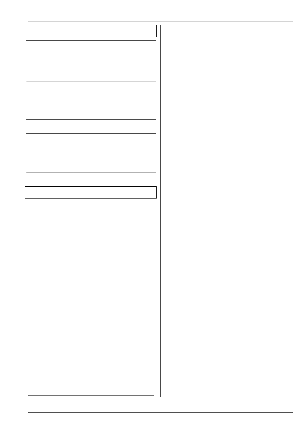
ROYAL SX
Model Memories
Channels
9
28
9
16
36
16
Frequency range
2.4000 GHz … 2.4835 GHz
Restricted frequency range:
2.4000 GHz … 2.4540 GHz
Transmission type
2.4 GHz FHSS M-LINK system
Frequency Hopping Spread Spectrum
MULTIPLEX-LINK
Transmission power
100 mW EIRP
Power supply
7.2 V, 6 AA cells
Charge current
max. 1.4 A (fast charge)
210 mA (normal charge)
Temperature range
Operation
Storage
Battery Charging
- 15 °C to + 55 °C
- 20 °C to + 60 °C
0 °C to + 40 °C
Dimensions
(L x W x H)
approx. 220 x 270 x 60 mm
Weight
approx. 900 g
7. Specification
8. The Transmitter Battery
The ROYAL SX is powered by a high-quality rechargeable PERMABATT+ battery consisting of six
AA-size NiMH (Nickel-Metal-Hydride) cells.
Features of the PERMABATT+ transmitter battery:
Capacity 2100 mAh
(approx. eight hours’ operation possible).
Self-discharge rate around 25% per year
(no recharging required even when stored for long
periods).
Fast-charge capable, max. 1.4 A
The pack must only be charged using a charger
with automatic cut-off: Delta-Peak cut-off at < 5 mV
per cell.
Normal charge at 210 mA
(corresponding to 1/10 C, charge for sixteen hours).
Integral over-current fuse, self-resetting
The battery is ready for use again approx. 1 s after
the excessive current is eliminated.
Avoid deep-discharging the battery (< 5.4 V).
If the transmitter or transmitter battery is to be
stored for a long period (several days), avoid temperatures above 30°C (brief maximum 55°C).
! The transmitter battery is responsible for the power
supply to the transmitter, and plays an important
role in operational security. For this reason it is essential to heed our recommendations regarding
charging and storing the rechargeable battery.
! The transmitter is fitted with a self-resetting fuse
which protects the battery and the transmitter from
short-circuit, reversed polarity and excessive currents. The transmitter electronics feature no additional fuse!
For this reason it is absolutely essential to use
genuine MULTIPLEX transmitter batteries in this
transmitter!
! Additional safety notes:
Batteries are not playthings, and must always be
stored well out of the reach of children.
Check that the battery is in perfect condition before
every flying session. Damaged or defective batteries must not be re-used. Dispose of them in the
authorised manner / recycling centre ( 8.8.).
Do not heat, incinerate, open or short-circuit re-
chargeable batteries, do not charge or discharge
them at excessive currents, do not overcharge
them, and do not charge with reversed polarity.
Place the transmitter or battery on a heat-resistant,
non-inflammable and non-conductive surface for
charging, and do not leave it on charge unsupervised.
Do not modify the battery pack in any way. Never
solder or weld directly to the cells.
Mis-handling the battery incurs a risk of combus-
tion, explosion, corrosion and burning.
Suitable extinguishing agents: water, CO2, sand.
Escaped electrolyte is corrosive!
Do not allow electrolyte to contact your skin or eyes.
In an emergency rinse the affected area with copious quantities of water, and call for medical assistance immediately.
Note:
Like many other technical components, rechargeable
batteries are the subject of constant development. For
this reason we reserve the right to alter the specification of the battery pack installed as standard, in order to keep abreast of technical developments.
8.1. Safety Notes
11
Page 14
ROYAL SX
8.2. Charging the transmitter battery
Never connect the transmitter to a battery
!
charger without a battery in the transmitter!
High voltages may be present at the charge out puts of battery chargers if no battery is connected.
These voltages can easily damage the transmitter.
Timer-controlled fast-charging, automatic cur-
!
rent setting systems and REFLEX charging
must not be used with this battery!
Fast-charge at max. 1.4 A!
!
This also applies if you remove the battery
from the transmitter for charging.
Important when fast-charging:
!
The battery charger must be suitable for NiMH
cells!
Delta-Peak cut-off sensitivity < 5 mV / cell
Charging using mains or 12 V chargers:
!
It is safe to leave the battery in the transmitter for
recharging. The charger should be connected
using the multi-function socket on the underside
of the transmitter ( 9.2.). Use genuine MULTIPLEX
charge leads (e.g. transmitter charge lead with
banana plugs # 8 6020). Please refer to the cur rent MULTIPLEX main catalogue for information
concerning other charge leads and battery char gers.
8.3. The correct method of charging
a. Switch the transmitter OFF.
b. Select a charger suitable for NiMH batteries,
switch it on and connect the charge lead to it.
c. Check correct polarity:
red plug = positive terminal (+)
blue / black plug = negative terminal (-)
Connecting the transmitter battery with reversed polarity may wreck the battery
(overheating, escape of corrosive electrolyte, cell
burst)!
d. Connect the charge lead to the transmitter
(back panel, CHARGE ( 9.2.)).
e. Select the charge current (max. 1.4 A).
If you are using an automatic fast-charger,
!
select the current manually!
f. If the battery becomes hot whilst on charge, to the
point where you can no longer touch the pack, interrupt the charge process immediately.
g. When the charge process is complete, first discon-
nect the transmitter / battery from the charger, and
then the charger from the power source.
h. When the charge process is complete, check the
charge quantity calculated by the battery management circuit, and correct it if necessary ( 8.4.3. a.).
8.4. ROYAL SX battery management
The term “battery management” means that the transmitter measures the current when the unit is in use
and when the battery is on charge. From this data the
software calculates the actual state of charge of the
battery, and displays it on-screen in Status display 4
( Fig. 8.4.1.) and in the main menu ¡Setup under
Transmitter ( Fig. 8.4.2.).
When the RF module is operating (LED flashes red)
the expected residual operating time is calculated
and displayed in Status display 4. This indicates how
long the transmitter should be able to operate if the
current drain remains the same:
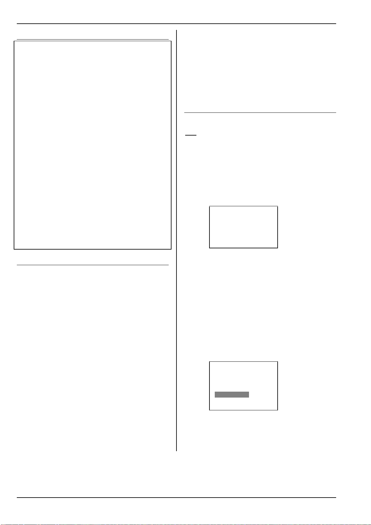
ROYAL SX16 3.46 DE/EN
M-LINK
Batt. voltage 8.20V
Battery charge 1998mAh
Remaining time 7.7h
Operating time 12.4h
Fig. 8.4.1.: Status display 4
8.4.1. Self-discharge
When the transmitter is stored, the system also takes
into account the battery’s rate of self-discharge, and
corrects the available battery charge quantity accordingly.
The ROYAL SX uses transmitter batteries of the type
PERMABATT+. The new manufacturing process used
for these batteries has reduced the rate of selfdischarge to around 0.07% per day (approx. 25% selfdischarge annually). The self-discharge rate of conventional NiMH batteries is around 1.5% per day.
For this reason the menu ¡Setup, Transmitter includes the menu point SlfDsCharge (self-discharge):
¡Transmitter
©
Battery
Alarm 7.10V
Capacity 2100mAh
Charge 1900mAh
SlfDsCharge low
Display
ª Contrast 0
Fig. 8.4.1.1.: Menu: Setup, Transmitter
In this menu point it is possible to switch the self-discharge rate between “low” (approx. 25% per year)
and “normal” (approx. 1.5 % per day). The factory default setting is “low”.
12
Page 15

Manual
Battery management only provides supple-
!
mentary information!
Battery charge and residual time represent additional
information relating to the condition of the transmitter
battery, and are intended to provide additional security
when handling the transmitter. However, major discrepancies may occur due to production tolerances,
battery ageing and the effects of battery maintenance.
In any case the system only works properly if the capacity and battery charge quantity ( 8.4.3.a.) are set
correctly when the battery is initially charged.
8.4.2. Unchanged features
Voltage display:
Virtually all modern transmitters display the actual battery voltage as a numerical value and / or in graphic
form (bar graph).
Battery alarm:
If the battery voltage falls below a certain minimum
value, the transmitter emits an audible alarm. On
many transmitters the alarm threshold is variable.
As you would expect, the ROYAL SX also includes
these two functions (Setting the alarm threshold
( 14.1.3.)).
8.4.3. This is important
To ensure that the battery management function displays values which are as close to “the truth” as possible, it is essential to observe the following points:
a. Correcting the battery capacity
The battery management function assumes that
the transmitter is fitted with a battery of 2100 mAh
capacity. When the transmitter battery has been
conditioned (more than five charge / discharge cycles) you can correct any discrepancy from the
nominal capacity as follows:
Menu: LSetup, Transmitter,
Parameter: Battery Capacity.
At this point you can set the value determined by
the battery charger (in increments of 50 mAh).
When the battery voltage falls below 6.5 V,
!
the available charge quantity is set to 0 mAh.
b. Correcting the available battery charge quantity
If you fit a new transmitter battery, or charge it di-
rectly (i.e. not via the socket on the back panel),
then the available battery charge quantity must be
corrected manually:
Menu: LSetup, Transmitter,
Parameter: Battery charge.
If the battery voltage is above 8.6 V when
!
the transmitter is switched on, the battery
charge quantity is set to the value which is set
for battery capacity in the menu ¡Setup,
Transmitter.
If the battery voltage falls below 6.5 V, the
!
available charge quantity is set to 0 mAh.
c. Charge the battery via the charge socket!
The battery management system can only
calculate the available charge quantity if you recharge the battery via the charge socket.
d. Normal charging at constant current (210 mA)
If you leave the battery connected to the charger
for longer than the period calculated according to
the formula in Section 8.5.1, the battery management system still displays the charge quantity
which you have set as the capacity in the menu
¡Setup, Transmitter.
8.5. Terms used in battery charging
Full capacity and potential performance ...
… are achieved by NiMH batteries only after several
charge / discharge cycles (~5 cycles). The initial charge /
discharge cycles should be carried out at 0.1 C (210
mA). Don’t fast-charge the battery until you have first
conditioned the pack in this way.
Charging at 1 C ...
... feeds 100% of the battery’s nominal capacity into
the pack in one hour in the form of charged-in energy.
For a battery of 2000 mAh capacity a current of
2000 mA is required to achieve this. If this current is
used for charging, we speak of a 1 C charge. This current value is found by simply taking the nominal capacity in mAh (or Ah), and omitting the “h” (hours).
8.5.1. Normal charging …
... means that the battery is charged at a current
within the range 0.05 C and 0.2 C. For a 2000 mAh
pack, for example, this means a charge rate of 100
mA to 400 mA.
To ensure that a rechargeable battery really is fully
charged, it is necessary to feed more than 100% of its
nominal capacity into the pack. The amount of the additional charge is defined by the charge factor.
The charge time for a flat battery is calculated as follows:
Capacity [mAh]
Charge time [h] = ------------------------------ Charge current [mA]
Note the charge factor for normal charging!
!
For PERMABATT+ type batteries of 2100 mAh the
charge factor is 1.6. Using a charge current of 210 mA
(1/10 C) a flat battery must therefore be charged for
sixteen hours if it is to be charged fully.
8.5.2. Fast charging …
... means that the battery is charged at a current in the
range 0.5 C to 1 C.
Observe the maximum charge current!
!
For PERMABATT+ type batteries of 2100 mAh the
maximum approved fast-charge current is 1.4 A.
In this case the charge time is determined by the fastcharger’s automatic cut-off circuit.
charge factor
*
13
Page 16

ROYAL SX
8.5.3. Trickle charging …
... means that the battery is charged at a current within
the range 0.03 C to 0.05 C.
Observe the maximum trickle charge current!
!
For PERMABATT+ type batteries of 2100 mAh capacity we recommend a trickle charge current of 20
mA to 100 mA. At a trickle charge rate of max. 105
mA the battery can safely be left connected to the
charger for up to a year.
Many automatic battery chargers switch to a trickle
charge current when the main charge process is terminated. If this is the case, we recommend that you
switch off the trickle charge no later than 24 hours after the charge process is complete.
8.6. Replacing the transmitter battery
If you replace the transmitter battery by a pack other
than a genuine MULTIPLEX battery, please note the
following:
Maximum current via the charge socket: 2 A!
!
Be sure to follow the charging instructions
!
provided by the battery manufacturer!
Set the self-discharge rate to suit the battery
!
type you are using! ( 8.4., Fig. 8.4.2.).
8.7. Transmitter battery care and storage
NiMH batteries should always be stored fully charged.
This avoids the danger of deep-discharging.
Store NiMH batteries at temperatures in the range 0°C
to 30°C, in dry conditions, away from direct sunshine.
Top up (recharge) unused NiMH batteries every six to
twelve months. This compensates for the selfdischarge effect, and avoids the danger of the cells
becoming deep-discharged.
Batteries which have been stored for a long period
should be conditioned (multiple charge / discharge cycles). Note that the usable capacity of such batteries
may diminish after a long period of storage.
8.8. Recycling
Do not dispose of exhausted rechargeable batteries in
the ordinary domestic waste. Take your old packs to a
suitable recycling centre. Make sure the batteries are
completely discharged beforehand, and insulate the
terminals to avoid the danger of short-circuit.
14
Page 17
Manual
1 9 8 1 7 6 2
10
9
3
4
5
9. The Transmitter
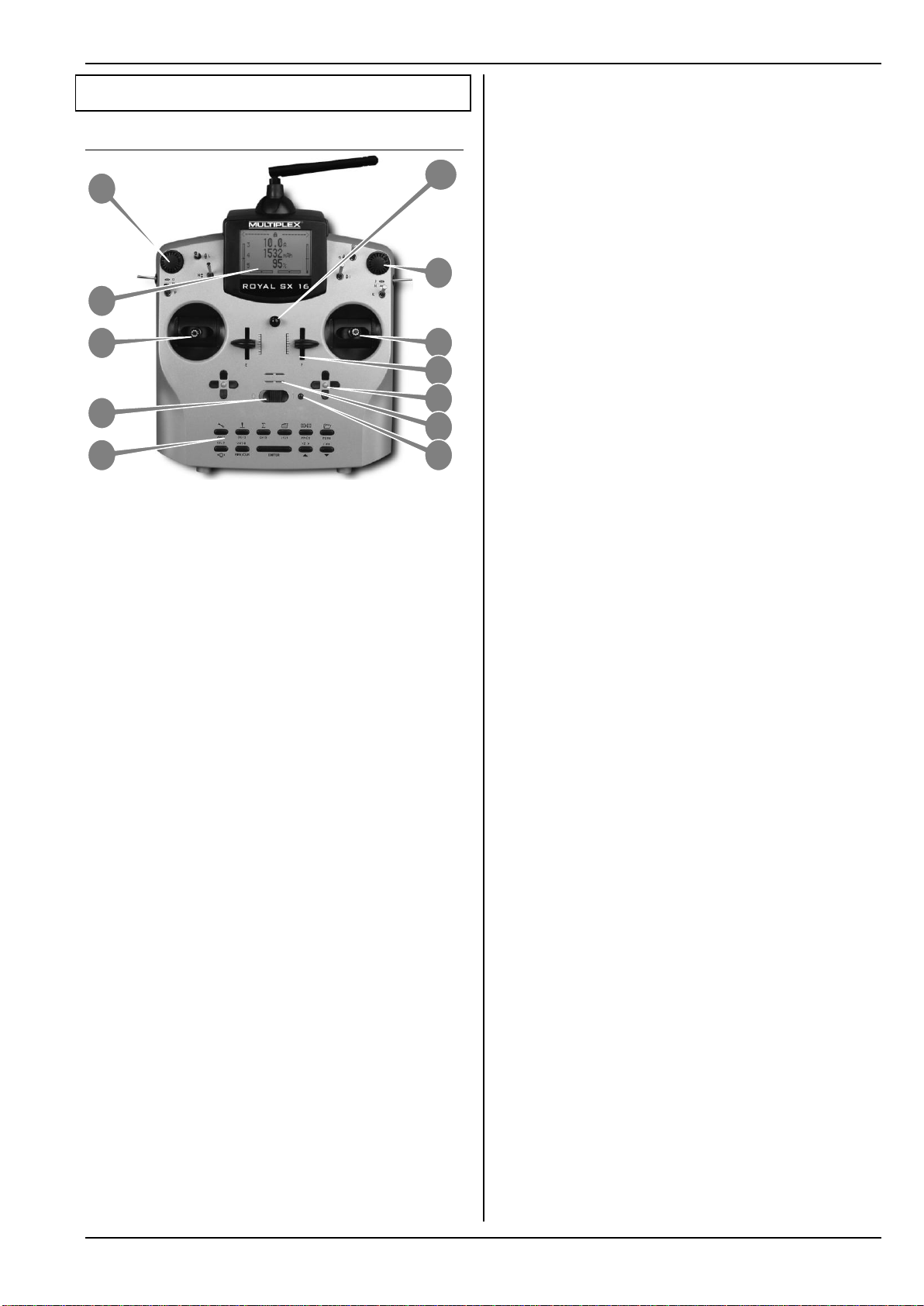
9.1. Front face of the transmitter
Fig. 9.1.1.: Front face of transmitter
(Switches K and P retro-fitted; not included as standard.)
The front face of the transmitter features the following
elements:
Two extremely accurate, ballraced stick units for
controlling the four primary axes. Stick ratchet for
throttle / spoiler can be activated right or left. Both
stick units can be swivelled to suit the pilot’s ergonomic preferences ( 9.4.7.). The stick tops rotate
and are infinitely variable in length; various types of
stick top are available.
With the exception of the “ENTER” button, all the buttons have a dual function for text input. Text is entered
in a similar way to mobile telephones ( 11.1.1.c.).
OFF / ON switch (“O” / “1”).
The screen is a modern, UV-stable, non-reflective
graphic LCD unit (132 x 64 dots) featuring variable
contrast ( 14.1.4.). The screen can be hinged
through around 40° to optimise the viewing angle.
Two 3-D digi-adjusters are used for program-
ming and set-up tasks. They are fitted as standard,
and are permanently installed. For programming, both
adjusters work in parallel with the “ENTER” button and
the “” (UP) / “” (DOWN) buttons. When using the
transmitter it is possible to allocate many different settings / parameters to the 3-D digi-adjusters, enabling
the pilot to adjust the settings quickly and easily while
the model is in the air ( 20.1.).
Neckstrap lug for attaching a support strap (e.g.
# 8 5161 or # 8 5646).
All the remaining control elements ...
… (switches / buttons “G” to “O”, apart from installa-
tion wells “K” and “P” ( 20.6.6.)), are installed as
standard in easily accessible locations. They cannot
be altered or interchanged.
The switch and button designations are neutral (“G”,
“H”, “I”, ... “O”, “P”) and are only intended for identification purposes, as they can be assigned to any
channel and / or switched function (transmitter control
or switch) ( 14.3.).
Two permanently installed proportional controls
(sliders “E” and “F”) with centre detent; available for
use with freely assignable channel functions and / or
switched functions.
Two cruciform trim groups below the stick units
for digital trimming of the primary control axes. They
consist of pairs of buttons for left / right and up / down.
Audible sounder (piezo beeper).
When the transmitter is switched on, the RF sta-
tus indicator / LED (red LED) indicates whether an
RF (Radio Frequency) signal is being transmitted:
LED glows constantly
no RF transmission
LED flashes every two seconds
RF being transmitted
The LED is controlled by the current drain of the RF
module. If the RF module is not drawing the corresponding current, or is not installed, the constantly
glowing LED warns you that an RF signal is not being
transmitted.
Keypad consisting of eleven buttons in two rows.
The six buttons in the top row provide fast, direct access to the six main menus (direct menu access buttons). The five buttons in the second row are used for
programming the transmitter.
15
Page 18

ROYAL SX
3 2 3 1 4 2 1
9.2. Rear face of the transmitter
Fig. 9.2.1.: Rear face of the transmitter
Two sliding latches (marked “OPEN”) provide a
fast, easy method of opening and closing the transmitter, e.g. for changing the RF module ( 9.4.2).
The robust carry handle provides a safe method
of carrying the transmitter, and also protects the rear
face when you set the transmitter down.
As is usual with MULTIPLEX, the ROYAL SX is
also fitted with a MULTIPLEX multi-function socket
installed as standard (marked “CHARGE”). It is used
as:
charge socket for the transmitter ( 8.2.)
socket for Trainer operations
( 14.4.1. and 14.4.2.)
PC interface for backing-up model data
( 20.2.)
PC interface for updating the transmitter
( 20.2.)
PC interface for flight simulators
( 20.3.)
interface for a ‘closed-loop’ receiver connection
(without RF transmission) for programming and adjustment work using a Diagnosis lead ( 20.2.).
The TORX
in clips in the transmitter’s back panel, is used for
various tasks such as adjusting the stick ratchet, friction and centring spring force, swivelling the stick
units, and for installing supplementary switches in the
installation wells “K” and “P”.
screwdriver (size T6), which resides
9.3. Interior of the transmitter
Fig. 9.3.1.: The interior of the transmitter
The transmitter battery fitted as standard con-
sists of six environmentally friendly, high-capacity AAsize NiMH (Nickel-Metal-Hydride) cells. For safety
reasons the individual cells are permanently interconnected and protected by a heat-shrink sleeve.
! Use genuine replacement batteries only!
Always heed the charging instructions!
( 8.2. and 8.3.)
The transmitter battery is fitted with a thermal fuse
which protects the battery - and above all the transmitter - from short-circuit, reversed polarity and excessive currents. The transmitter does not feature
a separate fuse. For this reason it is essential to
use genuine MULTIPLEX transmitter batteries designed for this transmitter.
RF module (Radio Frequency module). The RF
module is simply plugged into the main circuit board,
and can easily be changed if you wish.
Only RF modules of this type may be fitted to
!
the ROYAL SX!
Fig. 9.2.2.: TORX screwdriver in the transmitter back panel
16
Page 19
9.4. Mechanical details
OPEN
CLOSE
9.4.1. Opening / closing the transmitter case
! Switch the transmitter OFF before opening the
case (short-circuit hazard)!
Opening the transmitter case:
Fig. 9.4.1.1. Fig. 9.4.1.2.
a. Hold the transmitter in both hands, and push the
rear-mounted sliding latches down with both
thumbs (towards “OPEN”) ( Fig. 9.4.1.1.).
b. Carefully remove the rear case panel
( Fig. 9.4.1.2.).
Closing the transmitter case:
Manual
2. Carefully remove the back cover of the transmitter
case.
Plug in the HFM4 M-LINK 2.4 GHz RF module
1. Remove the HFM4 M-LINK 2.4 GHz RF module from
the protective anti-static bag, and hold it as described
above.
2. Carefully insert the RF module using steady pressure.
Ensure that the module is fitted on the correct pins,
and is inserted “squarely”, i.e. not canted over:
Fig. 9.4.1.3. Fig. 9.4.1.4.
c. Carefully stand the case at an angle on its rear edge,
and engage the two retaining lugs on the back panel
in their recesses
(arrows in Fig. 9.4.1.3.).
d. Carefully close the back panel ( Fig. 9.4.1.4.).
! Ensure that no wires are trapped, and that the
transmitter aerial has not slipped out of its guide
tube. It should be possible to fit the case back
easily, without using force.
e. Push the sliding latches up as far as they will go
(opposite direction to “OPEN”).
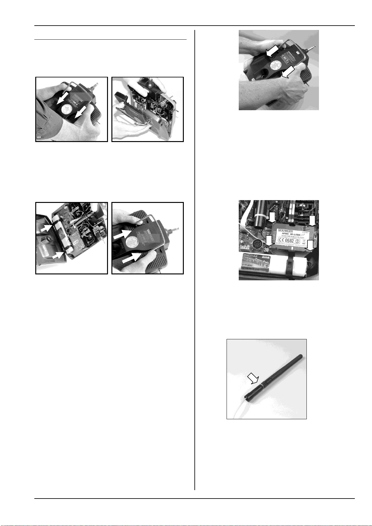
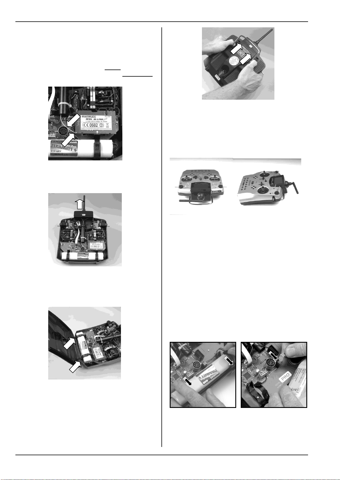
9.4.2. Removing / installing the RF module
The following section describes the method of
installing the HFM4 M-LINK 2.4 GHz RF module in a
transmitter of the ROYALevo, ROYAL SX or ROYAL
SX M-LINK type.
Open the transmitter case
! Switch the transmitter OFF before opening the
case (short-circuit hazard)!
1. Hold the transmitter in both hands, locate the sliding latches, and push both of them down using
your thumbs (in the direction marked “OPEN”):
Fit the 2.4 GHz aerial unit
1. Screw the 2.4 GHz aerial to the aerial base:
Hold the aerial by the knurled section.
Check that the resultant screwed joint is firm, to
ensure that the aerial cannot possibly come
loose in use, e.g. when swivelled in the installed
state:
! Note: avoid using excessive force, and keep
the parts correctly aligned when screwing them
together.
2. Set the prepared 2.4 GHz aerial unit straight (not at
an angle), then carefully slide it into the aerial
guide sleeve from the bottom end.
! Caution: the swivel base on the top face of
the transmitter must lie parallel with the aerial
guide sleeve during this stage. If you ignore
17
Page 20
ROYAL SX
this and hold the aerial at an angle, the wiper
contacts in the aerial guide sleeve could be
damaged.
3. Deploy the connecting lead from the RF module
and the aerial unit inside the transmitter:
The connecting lead must pass under the HFM4
M-LINK 2.4 GHz RF module and also to one side
of the MULTIPLEX multi-function socket:
4. Pull the 2.4 GHz aerial unit upwards out of the
aerial guide sleeve to the point where the aerial
joint is visible; you will feel a distinct mechanical
resistance at this point:
9.4.3. Ideal Transmitter Aarial Orientation When
Using the Transmitter
When installed, the 2.4 GHz transmitter aerial can be
rotated to either side and swivelled upwards.
Before using the transmitter, the aerial should be angled approximately at right-angles at the swivel joint,
then swivelled either to left or right in the horizontal
plane (see illustrations):
Close the transmitter case
1. Carefully offer up the case back panel to the
transmitter, inserting the retaining lugs at the bottom edge, and ensure that both lugs engage properly (arrows in the picture below):
2. Carefully close the transmitter back panel:
Ensure that no cables are trapped or jammed. It
should be possible to fold the case back into position without requiring force.
1. Push the sliders up as far as they will go (away
from the “OPEN” marking):
For applications where the model is not operated directly above or below the transmitter, the optimum aerial orientation is vertically upwards; this applies in
particular to model cars and boats.
! Important:
Never point the aerial directly at the model. For
physical reasons the signal radiated from the aerial is
at its weakest in an imaginary line extending straight out
from the aerial.
9.4.4. Replacing the transmitter battery
a. Switch the transmitter OFF!
b. Locate the snap-catches of the two plastic battery
retainers, pull both of them back in the direction of
the battery, then fold them up ( Fig. 9.4.4.1.).
c. Remove the battery and withdraw the battery con-
nector and lead from the socket on the main circuit
board ( Fig. 9.4.4.2.).
Fig. 9.4.4.1. Fig. 9.4.4.2.
Opening / closing the retainers Connecting the battery
When installing the battery ensure that the connecting
lead is neatly deployed, so that it cannot become trapped
when you close the transmitter back.
18
Page 21
Note:
(4) "Hardness"
centring force
right / left
(4) "Hardness"
centring force
forward / back
(1) Disable
neutralising action
(3) Strength of friction / ratchet
(2) Spring for
friction or ratchet
1 2 3
No model data is lost when you swap batteries.
9.4.5. Disabling the stick centring spring, activating the ratchet / friction system
ROYAL SX transmitters are supplied as standard with
self-centring sticks. The springs for use with a ratchet
or friction system are already fitted to both stick units,
and can be activated quickly and easily as follows:
Switch the transmitter OFF and open the case.
a. Locate the TORX screwdriver on the inside of the
transmitter back panel, and use it to tighten (turn
clockwise) the TORX screw on the appropriate
(please check!) neutralising lever (1) to the point
where the stick centring action is completely disabled. Don’t screw it in too far! On no account
remove the neutralising lever and centring
spring!
b. The screws (2) hold the springs, while the screws
(3) adjust the hardness of the ratchet / friction action: the further you tighten the screw, the harder
the ratchet or friction.
If you wish, you can set a superimposed ratchet / friction action by activating both springs on one stick.
This is simply a matter of personal preference.
Manual
Fig. 9.4.7.1.
a. Using the T6 TORX screwdriver (located in clips in
the transmitter back cover) ( Fig. 9.4.7.2.),
loosen the three TORX screws which retain the
appropriate stick unit until the unit can be swivelled.
b. Rotate the stick unit to the angle which seems
most natural to you ( Fig. 9.4.7.3.), then tighten
the TORX screws again. Don’t over-tighten them,
or you might strip the threads in the plastic.
Fig. 9.4.5.1.: Adjuster screws on the stick unit
9.4.6. Adjusting the “hardness” of the sticks
This term applies to the centring force of the neutralising spring on any one stick axis.
The ROYAL SX allows you to adjust the “hardness”
for each of the four stick axes separately. The picture
above shows how adjustments are made. The stick
axes become “harder” when you tighten the screws (4)
(turn them clockwise).
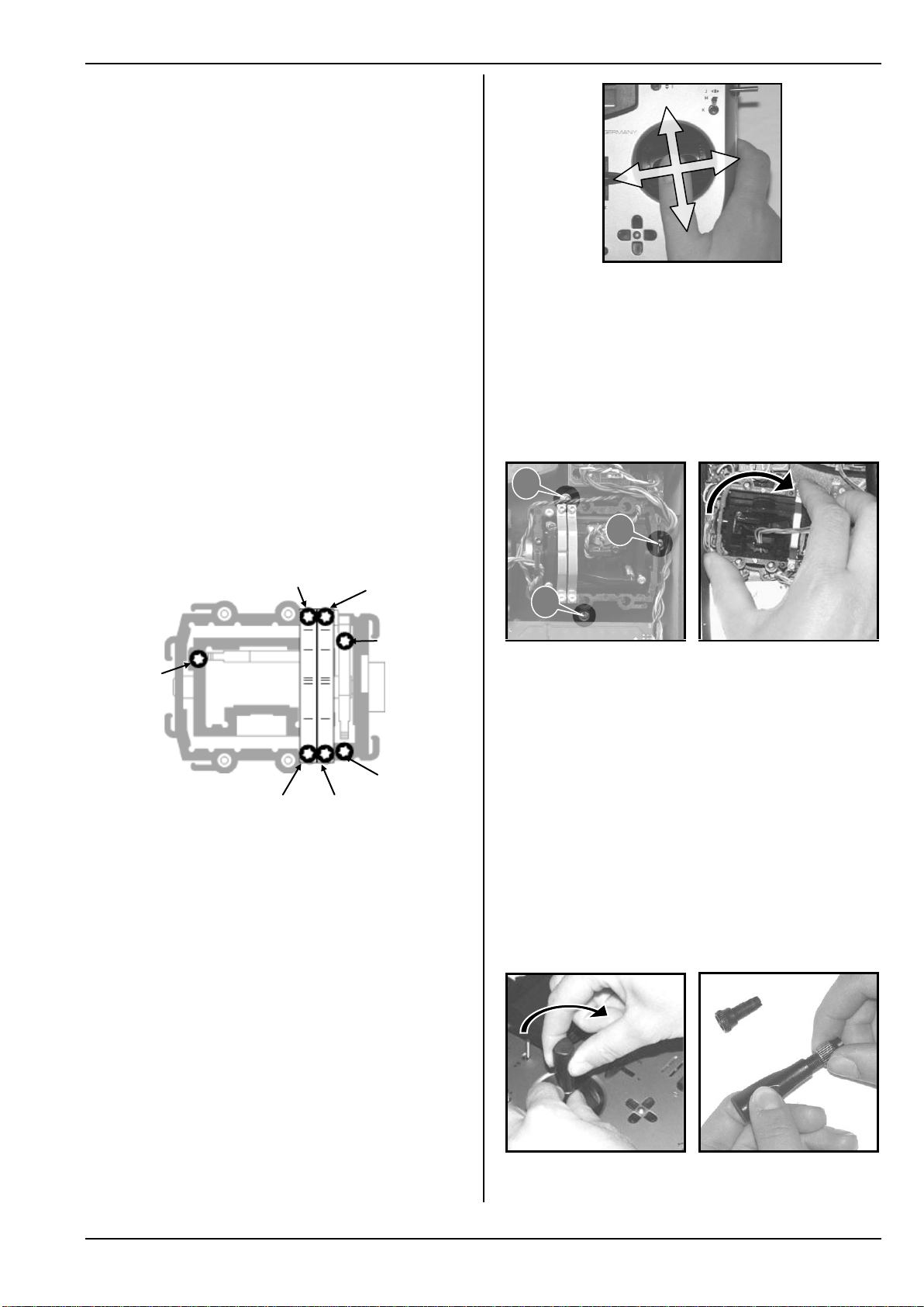
9.4.7. Swivelling the stick units
A unique feature of the ROYAL SX is that its stick
units can be swivelled to improve the ergonomics of
the transmitter. This is particularly advantageous if
you operate the transmitter hand-held, and use your
thumbs to control short sticks. In this case the “natural
working axis” is not exactly horizontal and vertical
relative to the transmitter, but at a more or less pronounced angle. Both stick units of the ROYAL SX can
be swivelled to any angle up to about 15° from the
nominal position.
Fig. 9.4.7.2. Fig. 9.4.7.3.
9.4.8. Adjusting / replacing the stick tops
The ROYAL SX is supplied as standard with three
pairs of stick tops of different lengths. They are easily
changed, rotated and adjusted in length:
a. Place the transmitter on a flat surface.
b. Hold the stick top in one hand, and loosen the
locking nut by turning it clockwise with your other
hand ( Fig. 9.4.8.1.).
The stick shaft is smooth, so the stick top can now be
rotated or adjusted in length. If you wish to change the
stick tops, unscrew the locking nuts and use them to
secure the alternative items ( Fig. 9.4.8.2.).
Before fitting the stick tops please ensure that the
shafts are clean and devoid of grease or oil. If you neglect this, the stick tops may not stay in position.
Fig. 9.4.8.1. Fig. 9.4.8.2.
19
Page 22

ROYAL SX
Dead zone
not
accessible
Centre Trim principle
Trim
Untrimmed
Standard
trim
Top
end-point
Bottom
end-point
Stick travel
Servo travel
KSw '
KSw #
C D
9.5. Plastic stick top with three buttons: installation and functions
If your model features important supplementary functions, the long stick top with push-button / switch
(# 7 5303, supplied with the transmitter) may be useful, as it provides a fast, simple and reliable method of
operating such functions without having to let go of
the stick.
Fig. 9.5.1. Fig. 9.5.2.
The top button KTa has a momentary function.
The two side-mounted buttons to-
gether form the switch KSw.
This stick top is connected to the
transmitter electronics by means
of two wires. The button and the
switched function can be assigned
to transmitter controls and
switches using the same procedure as for the other buttons (H
and M) and switches.
Fig. 9.5.3.
Fitting this stick top is quick and simple, and requires
no soldering:
a. Switch the transmitter OFF and remove the stick
top.
b. Locate the two connecting wires attached to the
stick top with the push-buttons, slip them through
the locking nut and the stick shaft ( Fig. 9.5.4.),
then install the stick top exactly as described in
Chapter 9.4.8.
Tip:
You will find it easier to thread the wires through
the stick shaft if you curve the cable ends slightly
and hold the stick in one corner position.
c. Clip the wires from the stick unit in the holders de-
signed for them. Check that the cables have plenty
of ‘elbow room’ when you move the stick, are
never under tension, i.e. they cannot become
trapped at any position of the associated stick.
d. Locate the appropriate screw clamp terminal block
on the main circuit board, and run the bare wire
ends to the clamps ( Fig. 9.5.5; small slot-head
screwdriver required) from the transmitter battery
side; you will need to remove the battery before
doing this. The two wires can be connected to terminals C and D either way round.
Fig. 9.5.4. Fig. 9.5.5.
Note: calibrating the stick buttons
!
When a stick top with push-buttons is first connected
to the transmitter, the software carries out an automatic calibration process. If you need to replace the
stick top for any reason, a re-calibration must be carried out; this will only occur if you reset the original
calibration using the PC program “ROYAL SXDataManager” ( 20.2.). For more information on this
procedure please refer to the instructions supplied
with the “DataManager”.
9.6. Digital trims
9.6.1. General information
The term “trimming” refers to the following procedure:
For example, you want your model aircraft to fly
straight and level when you leave the sticks exactly at
centre. If this is not the case, and the model always
tends to turn in one direction, you can adjust the neutral point of the corresponding control function (in our
example Rudder) to “trim” the model accurately.
The ROYAL SX features digital trims on all four axes
of the primary sticks.
The ROYAL SX exploits the “Centre Trim” principle,
i.e. trim corrections only affect the area around the
centre point of the transmitter control, without affecting
the end-points of the travel. Compared with “standard
trims” this offers the advantage that full transmitter
control travel (and thus servo travel) is always available, because no reserve has to be provided for trimming:
Standard trims:
If you move a stick with standard trims to the right, the
servo reaches its upper end-point before the stick
reaches its own end-point, as shown in the diagram
above. This means: a dead-zone at the stick.
20
Page 23

Manual
When the stick is moved to the left, the servo does not
reach full travel in the “down” direction. This means:
available servo travel which cannot be exploited.
Centre trims:
The servo runs to both end-points regardless of the
associated trim setting.
Tip:
Since Centre Trims alter the effect curve of the transmitter control, it is important to limit trim corrections to
small values. If a large correction is required, it is always best to adjust the mechanical linkage.
9.6.2. Advantages of digital trims
Digital trims offer two significant advantages:
1. The physical position of a conventional trim (with
trim slider) corresponds to the actual trim value,
but digital trim buttons do not. Instead the digital
trim position is displayed on the screen, and the
trim values are stored in the model memory. If you
switch model memories, the correct trims are immediately available, i.e. there is no need to move
the trim sliders to the correct position to suit the
model.
2. If the ROYAL SX is used with a model for which
you have set up multiple flight phases, each flight
phase has its own trim memory, i.e. it is an easy
matter to trim each flight phase accurately, and
independently of the trims in the other phases.
Starting from the trim centre position, the maximum
trim range is twenty increments in both directions. The
trim increment (step, or adjustment rate) can be set to
any of four magnitudes (0.5%, 1.5%, 2.5%, 3.5%) (
15.4.2.).
! Note regarding increment size and trim range:
the number of steps remains the same even if
you change the size of the trim increment,
with the result that both the trim range and
the absolute trim value also change! This
means: if you alter the trim increment size,
you must remember to re-trim the model.
The current trim value is displayed in graphic form on
the screen, but can also be read off as a numeric
value for each transmitter control (Parameter Trim
15.4.1.).
The type of graphic display can be selected in the
Status screen (Parameter Trim graph (Trim graphic)
14.1.4.).
Tip!
Resetting the trim to Centre:
Simultaneously pressing both trim buttons for any
stick axis resets the trim for the currently active flight
phase to Centre. This also applies to throttle trim.
9.6.3. The cruciform digital trims
In the case of the ROYAL SX, trimming is carried out
using the buttons arranged in a cross-shape below
and to one side of each primary stick unit. They are
located in an ergonomically efficient position, and are
easily reached when you are using the transmitter,
whether hand-held or in a tray.
The effect of each button-press is to shift the trim of
the associated control axis in the corresponding direction. If you hold the trim button pressed in for longer
than about 0.5 sec., the trim value changes continuously until you release the button once more
(AUTO-REPEAT function).
Each trim increment (step) is accompanied by an audible beep. When the trim reaches Centre or either
end-point of the trim range, the transmitter emits different beeps to inform you of the position. The trim
beeps can be switched OFF and ON ( 14.1.1.).
The trim of the fourth stick axis (‡) always
!
acts as throttle idle trim!
This also applies to gliders (powered gliders) if
this stick controls Spoiler, or model helicopters
if this stick controls Collect. (collective pitch).
9.6.4. On-screen trim display
The trim positions are displayed in graphic form at
both sides and the bottom of the screen in Status displays 1 - 3:
21
Page 24
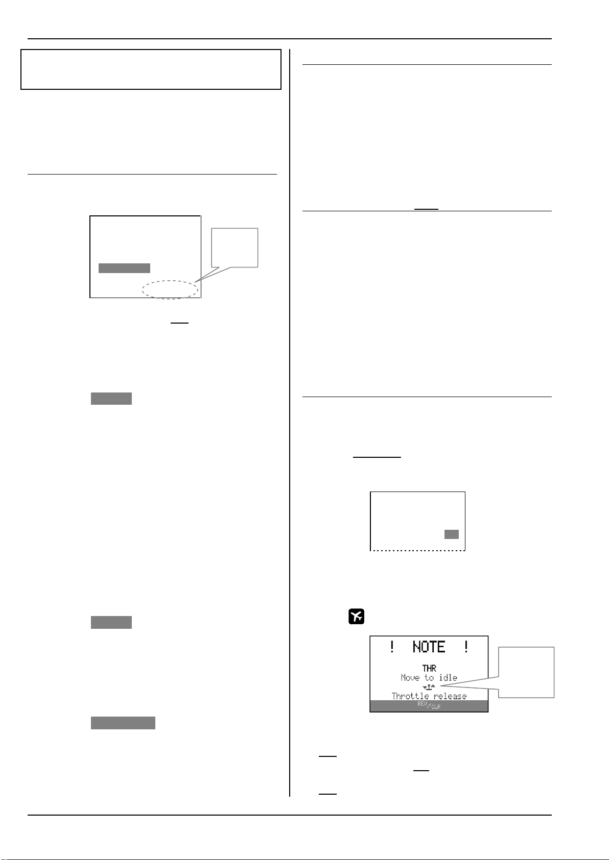
ROYAL SX
Only these
buttons are
active!
Indicator for
throttle control
(throttle stick
in this case)
10. Switching on, using the
transmitter
The ROYAL SX is supplied with the transmitter
!
battery partially charged. The pack must be fully
charged before you use the transmitter. Please refer
to the charging notes ( 8.).
10.1. Switching on for the first time
The very first time you switch the ROYAL SX transmitter on is a special case. When switched on, the
transmitter displays the following menu:
ROYAL SX16 3.46 DE/EN
Select language:
Sprache wählen:
skip/später
English
Deutsch ENTER ▲
In this menu you select the language which the transmitter will use for the menus and the names of the
pre-defined mixers and assignment lists. We recommend that you select the appropriate language when
you first switch the transmitter on:
Select the appropriate language using the ▲ and ▼
buttons, then press ENTER to confirm your choice.
If you select English:
a. English will be used as the menu language.
b. The pre-defined mixers are defined using English
terminology:
ELEVATR+, AILERON+, …
The mixer inputs are also described in English:
Aileron, Elevator, Rudder, …
If you change the selected language to German
(Deutsch) in the menu Setup, User, then the
names of the pre-defined mixers will continue to
appear in English, but the German terms will be
used for the mixer inputs:
Quer, Höhe, Seite, …
It is possible to change the names of all the fourteen free mixers to anything you like (Name parameter). This is accomplished in the menu Setup,
Mixer def..
If you select Deutsch (German):
a. German will be used as the menu language.
b. The pre-defined mixers are defined using the
German terminology:
HÖHE+, QUER+, …
The mixer inputs are also described in German:
Quer, Höhe, Seite, …
If you select skip/später (not recommended):
a. English will be used as the language.
b. Next time you switch on, the same menu will ap-
pear, and you can repeat the language selection.
10.2. Normal Operations
This is the procedure for operating your ROYALevo,
ROYAL SX or ROYAL SX M-LINK transmitter in nor-
mal mode:
1. Switch the ROYALevo, ROYAL SX or ROYAL SX
M-LINK transmitter ON:
The red LED on the transmitter flashes once
every two seconds.
2. Switch the M-LINK receiver ON.
The M-LINK system is now ready for use.
10.3. RF module excl. Scanner installed
The 2.4 GHz ISM band offers the facility to transmit
model data back to the transmitter. If you are using
a telemetry-capable M-LINK receiver, the actual voltage of the receiver power supply will be displayed directly on the integral screen of your
ROYAL SX
or
ROYAL SX M-LINK
transmitter. If the
ROYALevo
battery voltage falls below a certain threshold, the
transmitter also emits an audible signal to warn you
that the receiver battery is almost flat.
For more information on this feature, please refer to
the operating instructions supplied with your telemetry-capable M-LINK receiver.
10.4. Switching the transmitter on
with throttle-check active
Throttle-check is a safety function. If you are about to
fly a powered model, the throttle check (throttle lock)
prevents an electric motor bursting into life unexpectedly if you switch the system on when the throttle
channel is not at idle.
You will find the parameter Check Thr. in the menu:
Setup, Transmitter:
¡Transmitter
¨Exit
Sound All
Safety
Check Thr. ON_
Check RF ON
The factory default setting is ON. The conditions for
throttle-check are different for fixed-wing model aircraft
and helicopters; for this reason they are described
separately in the next two sections.
10.4.1.
This warning appears if:
Throttle-Check (Check Thr.) is set to ON (see above)
and
the throttle control is not in the idle position (or at
the motor OFF position)
and
Throttle-check for fixed-wing models
,
22
Page 25

Manual
Indicator for
the throttle
and throttle
limiter controls
the Throttle CUT switch has not been operated.
As long as the on-screen warning is visible, …
the servo assigned to throttle (or the speed control-
ler) remains in the Idle position (or motor OFF),
and
all other control functions can still be operated
normally.
The throttle lock is terminated when …
the throttle control is moved to the Idle position (or
motor OFF),
or
the Throttle CUT control is operated (default button H)
or
you press the REV/CLR button.
! Caution! The motor might start to run!
If you override the throttle lock using the REV/CLR
button or Throttle CUT, the throttle channel will jump
to the value defined by the assigned throttle control.
EMERGENCY throttle OFF is operated (default:
button H)
or
the throttle limiter is moved to the Minimum position
or
you press the REV/CLR button.
! Caution! The motor might start to run!
If you override the throttle lock using the REV/CLR
button or Throttle CUT, the throttle will jump to the
value defined by the assigned throttle control.
10.5. Binding Procedure
The transmitter and receiver must be “introduced” to
each other once; this process is known as “binding”.
! Note:
You will find general information on the subject of
binding, and on fault-finding and correction relating to
the binding procedure, in the operating instructions
supplied with your MULTIPLEX M-LINK receiver.
The binding procedure in detail:
10.4.2. Throttle-check for model helicopters
Helicopter throttle is affected by the following transmitter controls:
a. Throttle CUT switch (default: button H).
b. Direct Throttle switch
(DTC = Direct Throttle Control, default: switch N).
c. Collective pitch stick via the throttle curve.
d. Throttle limiter (default: slider F).
1. Place the transmitter and the receiver aerial(s) immediately adjacent to each other.
2. Switch the ROYALevo, ROYAL SX or ROYAL SX
M-LINK transmitter ON in binding mode:
Hold button L on the transmitter pressed in.
Switch the transmitter ON.
Release button L:
The red LED on the transmitter flashes rap-
idly, and the message “BINDING!” flashes
on the transmitter screen in all status displays with the exception of status display 4.
3. Switch the M-LINK receiver ON in binding mode
(see the
M-LINK receiver operating instructions):
This warning appears on-screen if:
Throttle-Check (Check Thr.) is set to ON ( 10.4.)
and
the collective pitch stick is not at the Idle position
(collective pitch minimum)
and
the Throttle CUT switch is not active.
As long as the note is visible on the screen, …
The binding process is now in progress.
4. Once the transmitter and receiver have detected
each other, both units automatically switch over
to regular transmit / receive mode (Normal operations 11.):
The red LED on the transmitter flashes ap-
proximately every two seconds, and the flashing message “BINDING!” disappears.
! Note: the binding process usually only takes a few
seconds
the servo assigned to throttle (or the speed control-
ler) remains in the Idle position (or motor OFF)
and
all other control functions can still be operated
normally.
The throttle lock is terminated when …
the collective pitch stick is moved to the Collective
Pitch Minimum position (provided that: point P1
on the throttle curve is lower than or equal to the
set value for Throttle Minimum Min.)
or
10.6. Range Checking
Regular range checks are very important - even when
using a 2.4 GHz system - in order to ensure reliable
operation of the radio control system, and to give you
a chance to detect sources of interference in good
time. This applies in particular:
Before the use of new or changed components, or
existing components in a new or modified arrangement.
Before re-using radio control system components
which were previously involved in a crash or a hard
landing.
23
Page 26
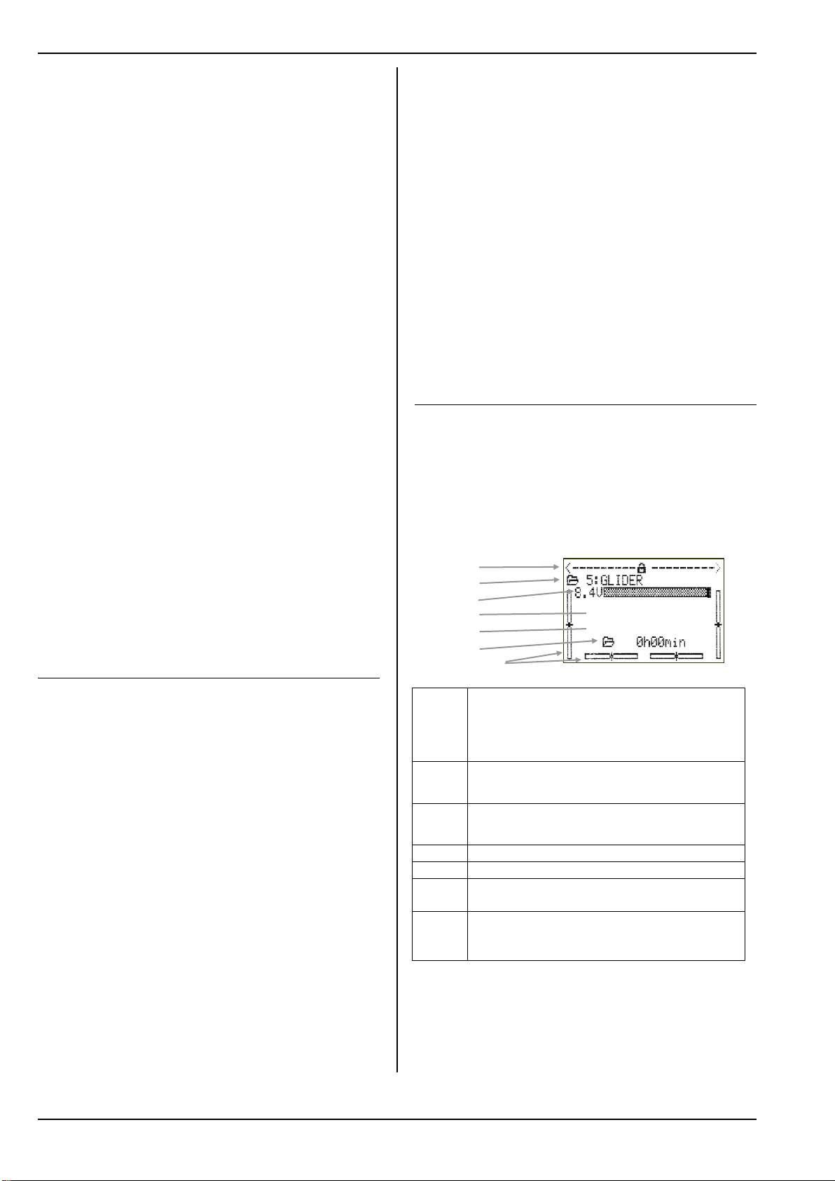
ROYAL SX
1
2
3
4
5
6
Bars
Line 1
Status of the 3-D digi-adjusters.
Numerous set-up parameters can be allocated to
the 3-D digi-adjusters, which can then be adjusted
while the model is flying ( 20.1.)
Line 2
Current model memory with memory number and
model name: 5:GLIDER
Line 3
Actual operating voltage of the transmitter battery in
numeric form and as a graphic bar display
Line 4
Transmitter type: ROYAL SX 9 or 16
Line 5
Owner’s name ( 14.5.3.)
Line 6
Operating time for the currently active model memory ( 18.2.)
Bars
The four bars at the sides and bottom indicate the
current trim positions for the four primary control
functions / sticks
SX 16
MULTIPLEX
If you have encountered problems on a previous
flight.
Important:
Always ask a second person to help you with your
range check, so that one of you can secure and observe the model.
If possible, carry out the range check when no other
trans-mitters are operating.
Preparations, carrying out the range check:
5. Select “Range check” mode on the transmitter:
Hold button F on the transmitter pressed
in.
Switch the transmitter ON.
Release button F:
The red LED on the transmitter now glows
constantly, and the message “RANGE!”
flashes on the transmitter’s screen in all
the status displays with the exception of
status display 4.
6. Switch the M-LINK receiver ON.
7. Carry out the range check as described in the op-
erating instructions supplied with your M-LINK receiver.
8. When the range check is completed, switch the
M-LINK transmitter OFF, and then ON again, in
order to switch back to full range.
! Caution: selecting “Range check” mode re-
duces the transmitter’s output power. The trans-
mitter emits an audible signal every ten seconds
or so to warn you of this. Never attempt to fly a
model with the transmitter set to reduced output
(Range check mode)!
5. Mark the menu point FastResponse by rotating
one of the
3-D digi-adjusters, or by pressing the button.
6. Press the ENTER button or one of the 3-D digiadjusters.
7. Select one of the options ON or OFF by turning one
of the
3-D digi-adjusters, or by pressing the or but-
tons.
8. Confirm your selection by pressing the ENTER
button, or by pressing one of the two 3-D digiadjusters.
9. Quit the menu.
! Note:
If you enable or disable Fast Response mode, you
must repeat the binding process between transmitter and receiver ( 9.)!
10.8. The Status displays
“Status display” is the term we use for the four different screen displays which appear as options when the
transmitter is “started” (with or without RF transmission).
You can switch between the individual Status displays
using the “” or “” buttons.
10.8.1. Status display 1 (standard)
10.7. Fast Response ON/OFF
In Fast Response mode, which operates at the ultrarapid pulse rate of 14 ms, up to twelve servo channels
are available. This reduced pulse rate can cause analogue servos to oscillate or run jerkily.
If this occurs, or if you need to use the maximum of
sixteen servo channels, it is possible to switch Fast
Response mode OFF on the ROYALevo, ROYAL SX
or ROYAL SX M-LINK transmitter. The pulse rate is
then 21 ms.
Please refer to the notes in the operating instructions
supplied with your ROYAL SX M-LINK transmitter in
this regard.
This is the procedure for switching Fast Response ON
or OFF if you are using a ROYALevo, ROYAL SX or
ROYAL SX M-LINK transmitter:
1. Switch the transmitter ON.
2. Press button I on the transmitter.
3. Mark the menu point Modulation by rotating one
of the
3-D digi-adjusters, or by pressing the button.
4. Press the ENTER button, or one of the 3-D digiadjusters.
24
10.8.2. Status display 2 (flight phases)
Page 27
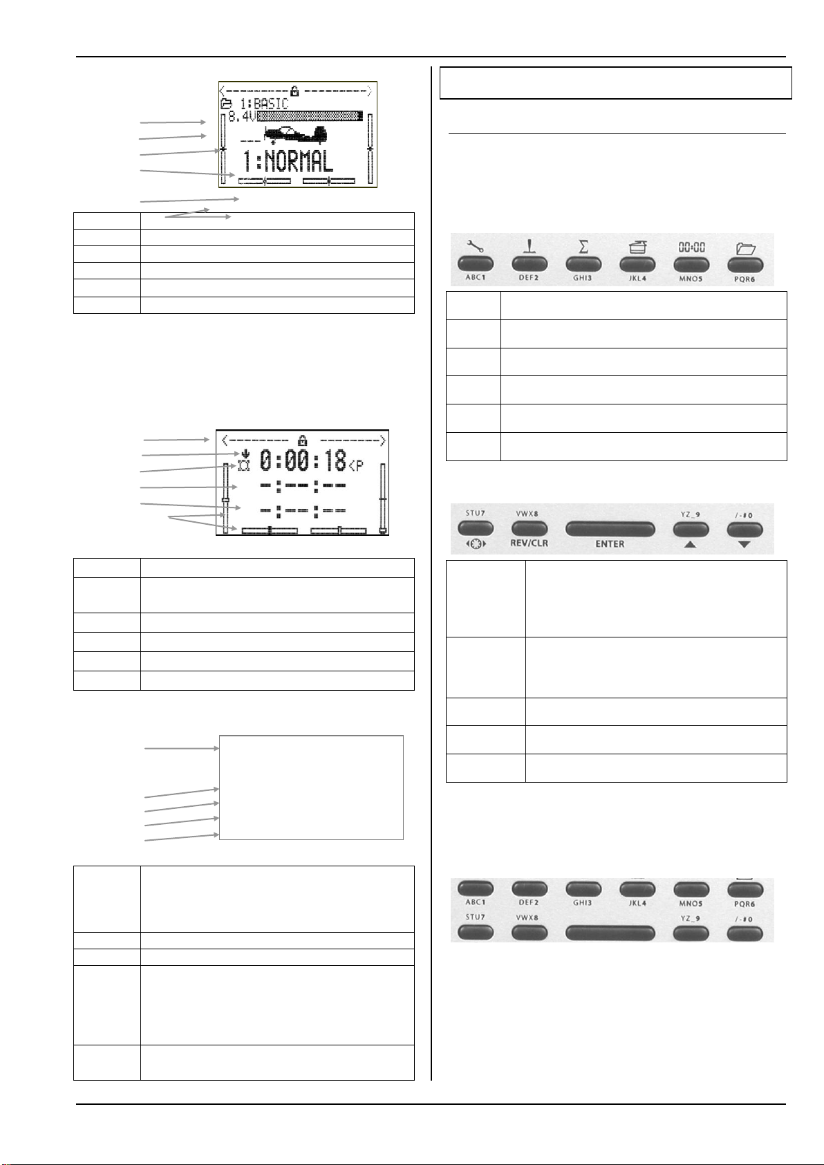
1
2
3
4
5
Line 1
Status of the 3-D digi-adjusters ( Status display 1)
Line 2
Current model memory ( Status display 1)
Line 3
Actual battery voltage ( Status display 1)
Line 4
Switch used to select the current flight phase ( 19.4.)
Line 5
Current flight phase with number and name: 1:NORMAL
Bars
Current trim positions ( Status display 1)
1
2
3
4
5
Bars
Line 1
Status of the 3-D digi-adjusters ( Status display 1)
Line 2
Direction of operation of each timer (here: counting
down)
Line 3
Slot timer ( 18.3.)
Line 4
Sum timer ( 18.4.)
Line 5
Interval timer ( 18.5.)
Bars
Current trim positions ( Status display 1)
1
2
3
4
5
Line 1
Transmitter type: ROYAL SX 9 or 16
Software version: e.g. 3.46,
Loaded language set:
e.g. DE/EN (German / English)
Line 2
Actual battery voltage
Line 3
Available battery charge quantity
Line 4
Calculated remaining transmitter operating time
based on the available battery charge quantity and
the actual current drain. Only displayed if an RF signal is being transmitted.
The red LED must flash!
Line 5
Transmitter operating time, up to 1000.0 hours,
then restarts at 0.0 h
L
Setup (Configuration)
H
Control
G
Mixer
K
Servo
A
Timer
I
Memory
F
Allocate 3-D digi-adjuster for:
altering values in flight 20.1.
calibrating servos 17.1.2.
Activate scanner when switching on
REV/CLR
Reverse (REVerse) Erase (CLeaR).
Many set-up values (% values) can be restored to
the default setting using this button
ENTER
Menu / Open / Close parameter
Cursor up / Increase values
Cursor down / Reduce values
ROYAL SX16 3.46 DE/EN
M-LINK
Batt. voltage 8.20V
Battery charge 1998mAh
Remaining time 7.7h
Operating time 12.4h
10.8.3. Status display 3 (timers)
The screen only displays those timers to which a
switch has been assigned. After the timer the screen
shows the associated switch (in this example: the Slot
timer is controlled using switch “P”):
Manual
11. The “ROYAL SX” philosophy
11.1. Operating the ROYAL SX
11.1.1. Using the keypad
The ROYAL SX is programmed using the keypad and
the two 3-D digi-adjusters. There are eleven buttons in
all.
a. Six buttons for direct access to main menus
10.8.4. Status display 4 (system information)
b. Special function buttons
c. Text input buttons
The ten buttons with inscribed letters are used for entering text (name of transmitter owner, model, free
mixers, assignment lists):
25
Text is entered in the manner familiar from mobile
telephones. The two 3-D digi-adjusters can be used to
select individual characters in the input field.
The characters which can be called up by rapidly and
repeatedly pressing one button are printed in small
script below the direct menu access buttons (row 1)
and above the working buttons (row 2).
Page 28

ROYAL SX
Button
Character
ABC1
A B C Ä 1 a b c ä
DEF2
D E F 2 d e f
GHI3
G H I 3 g h i
JKL4
J K L 4 j k l
MNO5
M N O Ö 5 m n o ö
PQR6
P Q R 6 p q r
STU7
S T U Ü 7 s t u ü
VWX8
V W X 8 v w x
YZ_9
Y Z 9 y z _ ( )
{ }
/-#0
0 / ? ! - + % # & < >
*
Status displays
( 10.8.)
Entry into the main menus using
one of the six menu buttons
Main menus
xxxx ....
Branches into menus
Menus
xxxx ....
Branches into sub-menus
Variable parameters
Fixed parameters (information
Sub-menus
Variable parameters
Fixed parameters (information
only)
When you enter a letter at the start of a text input, or
after a space, this is automatically displayed as a
capital letter, with the following letters automatically
set in lower case. If you wish to enter a series of capital letters, simply ‘leaf past’ the lower-case letters, and
the capitals will follow. When you select a letter, the
cursor automatically moves on to the next position.
The cursor can also be moved forward or back manually to any position using either of the two 3-D digiadjusters.
Text input is concluded by pressing the ENTER button. The screen now displays a request to input text:
Clear rest
of line?
Yes ->
No -> ENTER
Pressing the REV/CLR button erases all inputs af-
ter the last position of the cursor.
Pressing ENTER leaves the text unchanged.
Entering special characters:
Certain buttons can also be used to enter characters
in addition to the printed ones, such as accented letters and other special characters:
REV
/CLR
11.2. The ROYAL SX menu structure
You will find a diagram of the ROYAL SX menu structure in the coloured A3 supplement to the manual.
Please refer to the supplement when reading this section.
The ROYAL SX has four menu levels:
Status displays (not shown in the Overview)
Main menu
Menu
Sub-menu
The Status display supplies information about the
transmitter and the current model, and is divided up
over four screens. You can switch between the displays using the ▲ and ▼ buttons. The Status display
appears when you switch the transmitter on, or when
you leave the main menus. The four Status displays
are not shown in the Overview. Please see Chapter
( 10.6.) for details regarding the Status display.
The six main menus are called up using the six direct
menu access buttons. Within the main menus all you
will find is branches leading into the menus themselves. Each branch is always indicated by a series of
four full stops.
The menus can contain both branches into sub-
menus, as well as parameters.
The sub-menus only contain parameters.
Parameters are variable values which appear in
menus and sub-menus. Some only provide information, but others are in a form which can be altered.
Invariable parameters are skipped when you leaf
through the menus.
Space character
11.1.2. Using buttons when operating a model
The REV/CLR button resets all timers to
the set alarm times.
The 3-D digi-adjusters can be allocated
to any parameter which is marked in the menus with a
hyphen “-” ( 20.1.).
Button F is used to unlock / lock the values allocated for adjustment:
Fig. 11.1.2.1.: Aileron Expo allocated to the right-hand 3-D
digi-adjuster
a. Value locked b. Value unlocked
26
Fig. 11.2.1.: Menu structure in principle
Page 29
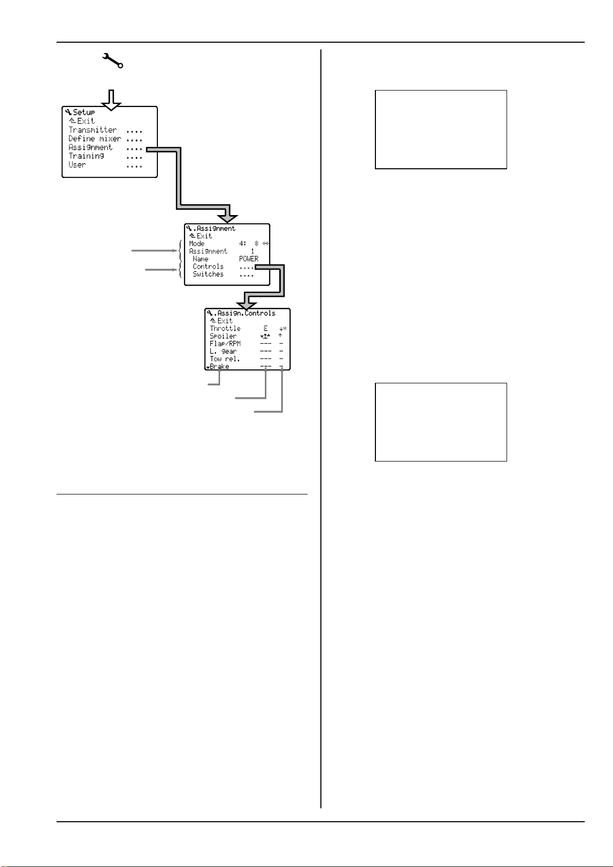
Setup
Main men u: Setup
with branches in to the menus
Menu: Assignment
with parameters
(Mode, Assignment, Name)
and branches
into sub-menus
(TX Controls, Switches)
Sub-menu: Assign Controls
with parameters
TX control
Operating element
Idle position and status
Fig. 11.2.2.: Typical menu structure
11.3. What do the sticks, sliders and
11.3.1. What does “Assignment” mean?
The assignment defines which transmitter control is
used to operate a function in the transmitter or the
model. This information is stored in the assignment
lists.
The software differentiates between
Controls ( 11.3.2.) and Switches ( 11.3.3.).
The assignment lists do not include the basic functions (aileron / elevator / rudder for fixed-wing models,
roll / pitch / yaw / collective pitch for helicopters).
These functions are covered by the stick mode
(Modes 1 to 4).
11.3.2. What are transmitter controls?
Controls are all those elements on the transmitter
which operate functions in the model (servos, speed
controllers, gyros, …). The following controls are
available:
a. Sticks
(e.g. for throttle, spoilers, ...).
b. Sliders E and F
(e.g. for flaps, mixture, gyro, ...).
c. Switches and buttons, including those on the
sticks
(e.g. for retracts, aero-tow release, ...).
switches do?
Or: Global assignments (lists)
Manual
The menu ¡Setup, Assignment, Controls contains
a list of all the transmitter controls which are managed
by the software:
¡Assign.Controls
¨Exit
Throttle ‡ #*
Spoiler E '
Flap/RPM F #
L. gear --- Tow rel. --- ªBrake --- -
In this menu you can change the assignment of the
controls in any way you wish, i.e. you can change the
arrangement to suit your personal preferences.
11.3.3. What are switches?
Switches are all those elements which control trans-
mitter functions such as Dual-Rate, Combi-Switch,
Timer, Flight phases, …
The menu ¡Setup, Assignment, Switches contains a list of all the switches which are managed by
the software.
Transmitter controls can also be used to switch certain functions. Example: the motor run time can be
recorded using the timer ´ (sum timer), if you use the
throttle control as the switch to control this timer. It
makes no difference whether the throttle control is a
stick, a slider or a switch:
¡Assign.Switches
¨Exit
DR-ai <L #*
In this menu you can change the switch assignment
exactly as you wish, i.e. to suit your personal preferences and requirements.
11.3.4. Why “global” assignments?
Every model pilot has his own ideas about the ideal
layout of the transmitter controls.
Examples: when flying power models a pilot may always control throttle with the stick, but use switch G
for his electric gliders. The glider aero-tow release
might always be switch I. When flying model helicopters he may always control idle-up with slider F.
To ensure that our pilot is not obliged to enter this information for each new model, he uses “global” assignment lists for each model category (maximum five
lists). Once he has defined the control assignment at
this point, it can be used for as many models of the
same category as he likes.
The fact that these lists can be altered at any time is
one factor in the flexibility of the ROYAL SX. However, a high level of standardisation is important in
order to avoid confusion, and that is why we limit the
number of assignment lists to five. This level of standardisation also helps to avoid operating the wrong
controls in flight.
If you subsequently wish to change an assignment,
perhaps to take into account new methods of control
or habits, all you have to do is enter the change in the
DR-el <L #*
DR-ru <L #*
CS/DTC <N #
Throttle-cut H> „
ªµSlot --- -
27
Page 30
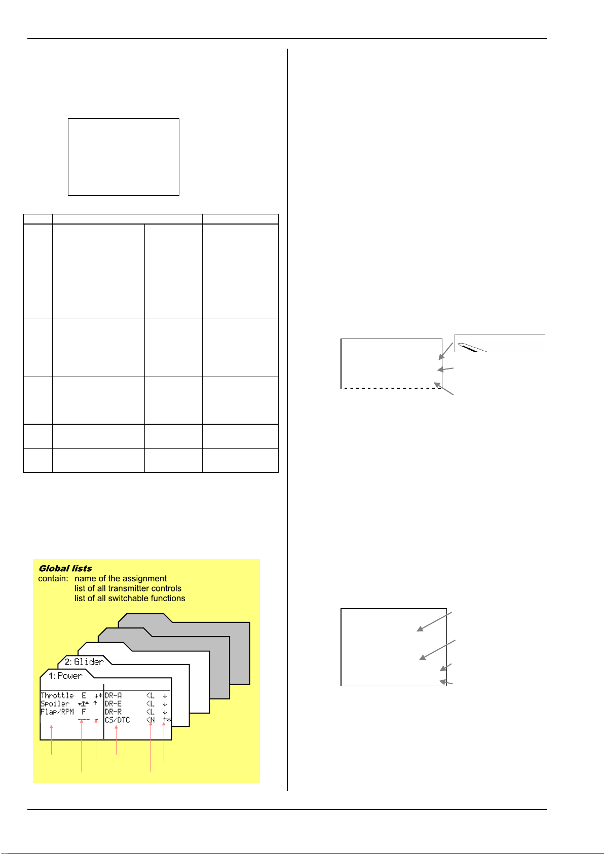
ROYAL SX
Line
Menu point
Meaning
1.
Mode
1: è é
For Mode 1 this
means:
Elevator and
rudder on the left
stick;
can also be
changed in this
menu point
2.
Assignment
1
Selected list is
No. 1;
can also be
changed in this
menu point
3.
Name
BASIC
Name of the list;
can also be
changed in this
menu point
4.
Controls
....
On to control assignment list
5.
Switches
....
On to switch assignment list
3:
HELI
4:
-----
5:
-----
Control
Switch
Control
Assigned control
Status
Function
Assigned switch
Status
L. g ear
1.
2.
3.
4.
5.
Spoiler on the stick,
Idle forward, active
Flap on slider F,
Idle back, not active
Dual-Rate on switch L
(ON position back)
Combi-Switch on switch N
(ON position forward)
Throttle-cut on button H
(active when button is pressed)
Slot timer
(no switch assigned)
appropriate assignment list, i.e. you do not need to do
this separately for each individual model.
The menu ¡Assignment contains all the information
concerning the current assignment for your model.
Example:
¡Assignment
¨Exit
Mode 1: è é
Assignment 1
Name BASIC
Controls ....
Switches ....
The function of the individual menu lines is as follows:
Fig. 11.3.5.1.: Global assignment lists
Please refer to ( 22.1.) for information on the default
assignments.
11.3.6. How are the assignment lists arranged?
The assignment lists contain all the transmitter controls and switches which can be used when programming.
The second column indicates the control element to
which the transmitter control or switch is linked. The
arrows adjacent to the switch code letters indicate
whether the switch is positioned on the left (<N) or
right (G>) side of the transmitter.
The third column (Status) includes an up-arrow or a
down-arrow; these have the following meaning for
transmitter controls and switches:
a. In the Controls assignment list
The arrow shows the location of the “Idle” position
of the transmitter control.
' = forward, # = back
The asterisk “*” following the arrow appears when
the control is actually in the Idle position.
Example:
¡Assign.Controls
¨Exit
Throttle E #*
Spoiler ‡ '*
Flap/RPM F #
For fixed-wing models: Idle for throttle, spoiler /
landing gear retracted.
For helicopters: coll. pitch min., motor OFF position
for throttle limiter.
For the other transmitter controls the Idle position
11.3.5. Which assignment lists are available?
The ROYAL SX provides five assignment lists: three
are pre-defined, and bear the names POWER, GLIDER,
HELI. Lists 4 and 5 are empty; by default they are
named “4.......” and “5.......”. All five lists and
their names can be changed in any way you wish.
only has a subordinate significance.
b. In the assignment list Switches
The arrow indicates the direction in which the function is switched on.
DR-ai (Dual-Rate aileron), CS/DTC (Combi-Switch /
Direct Throttle), Throttle-cut, Timers etc.
The asterisk “*” following the arrow appears when
the switch is currently at the ON position (function
active).
Example:
¡Assign.Switches
¨Exit
DR-ai <L #
DR-el <L #
DR-ru <L #
CS/DTC <N '*
Throttle-cut H> „
ªµSlot --- -
11.3.7. How are the assignment lists used?
When you set up a new model in a memory ( 12.2.6.
and 13.2.6.), you can select one of the five lists.
28
The name of the list is intended to describe the model
category for which the list was created, rather than a
specific model (i.e. “E-glider”, rather than “Cularis”).
Page 31

Manual
1.
Suggested names: E-heli, E-glider if, for example,
you wish to use different assignments for your electric
models to their equivalents with I.C. motors.
Tip: we recommend that you set up the list to cover
the most complex model which you own in that particular category. For example, it presents no problem
if the Glider list includes, say, assigned transmitter
controls for flaps and retractable wheel, even if your
current model is just a simple rudder / elevator glider.
11.3.8. Summary: “Global assignments”
Five global assignment lists are available.
Three assignment lists are pre-defined.
All list names and assignments can be changed.
11.4. Global mixer definitions
11.4.1. Why “global” mixer definitions?
As in the case of assignments, there are particular
mixer configurations which modellers use again and
again. For this reason we have separated the mixer
definitions from the process of setting up the individual mixer input values for a particular model.
The definition is entered “globally” in menu L
(Setup), Mixer def. (see illustration below). Once
defined, a mixer can be used as often as you like for
any number of models.
When a mixer is defined, the following points are determined:
1. A name for the mixer.
2. A maximum of five mixer inputs.
3. A switch for the mixer inputs.
4. The method of working of the mixer inputs.
¡Define mixer
¨Exit
Name AILERON+
1 Aileron ON ™2
2 Spoiler ON ›+
3 FLAP ON š
4 Ele-Tr Mx1 š
5 -------- ---- --
2. 3. 4.
The magnitude of the mixer inputs is set individually
for each model in the menu £Mixer.
11.4.2. Which global mixers are available?
The ROYAL SX includes fourteen free mixers. Five of
them are pre-defined, and can be used immediately.
All the mixers - including the pre-defined ones - can
be changed exactly as you wish.
Please refer to the overview ( 22.2.) “Pre-defined
mixers” for information on the default mixer definitions.
Tip: the mixer definition should cover the most
complex application for which you are likely to want to
use the mixer. If the model is a glider whose ailerons
you “only” wish to raise for landing, you can use the
AILERON+ mixer. The inputs Flap and Ele -tr can
simply be left at “OFF” when you are setting up the
mixer inputs in the menu £Mixer. However, those
inputs remain available in the definition even though
they have no effect on the present model, assuming
that they are not set up and activated for that model.
11.4.3. Mixer names with a “+” suffix
You will see a “+” suffix attached to the names of the
pre-defined mixers. This indicates that, for example,
the AILERON+ mixer includes other inputs in addition
to the basic Aileron function. These mixer names are
also displayed in capital letters (ELEVATR+, AILERON+,
FLAP+, …), to differentiate them more clearly from the
basic inputs (Elevator, Aileron, Flap).
11.4.4. How are the free mixers used in fixedwing model aircraft?
You might care to think of the free mixer definitions as
a collection of building blocks, from which you select
the most suitable for any particular model. The “selecting” is carried out when you assign the servos in
the model. Only if a mixer is assigned to at least one
servo (menu ¤Servo, Assignment) does the mixer
appear in menu G (Mixer); you can then set the values
for the individual mixer inputs.
The illustration below shows the building block collection and the fourteen mixer building blocks:
Example:
£5x Mixer.AILERON+
¨Exit
™2 ---- trv
Aileron__–----- 80% *
Spoiler – OFF OFF *
Flap – OFF OFF *
Ele –Tr – OFF OFF G-
--------–-----------
In the line above the mixer inputs, the screen shows
the method of working of the selected mixer input and
the meaning of the variable values.
Fig. 11.4.4.1.: The free mixers
Important: a maximum of five free mixers can be
!
used simultaneously in any one model memory.
29
Page 32

ROYAL SX
1. BASIC
7. HELImech
2. ACRO
8. HELIccpm
3. HOTLINER
4. DELTA
5. GLIDER
6. 4 FLAPS
11.4.5. How are mixers used in helicopters?
For model helicopters the mixers required to control
the various rotor head types and the tail rotor are preprogrammed as standard. As a result, the free mixers
(1 to 14) cannot be used when assigning the servos
for model helicopters.
However, there are three free transmitter control mixers, and they can be used to mix the signals from the
controls ROLL, PITCH and YAW into the transmitter controls ROLL, PITCH, YAW, THROTTLE or COLLECTIVE
PITCH.
The most important application for these facilities is
the various compensation mixers, in which all the control functions are mixed into THROTTLE. For example, these mixers make it possible to compensate for
the increased power requirement when the pilot
makes deliberate control commands.
The settings in these mixers might look as follows:
£Comp.Mix.CRUISE
©
Aileron ™ -> Throttle
Travel — 10%
Elevator™ -> Throttle
Travel — 10%
Rudder š -> Throttle
Travel+ — -5%
Travel- — 17%
Roll and Pitch (-axis) are mixed into Throttle
symmetrically. Separate values for “left” and “right”
can be entered for yaw.
11.4.6. Summary of the “free mixers”
Fourteen free mixers are available.
Mixer names (max. eight characters), mixer inputs,
switches and method of working can be changed
in all mixer definitions.
Up to five free mixers can be used simultaneously
for a particular model.
Every mixer you use can be assigned to as many
servo channels as you wish.
The menu £Mixer only displays those mixers to
which at least one servo has been assigned.
Only Control mixers are available for helicopters.
11.5. Model templates
11.5.1. Why are model templates needed?
The model templates make it much easier and quicker
to set up new models, as a large part of the routine
work is accomplished just by selecting the appropriate
template. Use a template, and you can immediately
start entering the settings for the model.
The model templates themselves cannot be changed.
However, when you set up a new model and load a
copy of the template into the model memory, you can
then access it and make changes as needed.
Advantage: since the template itself cannot be altered (even accidentally), it is always available in the
exact form described in the Manual.
11.5.2. What do the model templates contain?
a. Basic mixer settings
The main input is set to full servo travel; all other
inputs to OFF.
b. Basic transmitter control settings
Travel and Dual-Rate to 100%
Expo to 0%
Trim increment to 1.5%.
c. Basic servo settings
Servo travels 100%
Centre to 0%.
d. Basic flight phase settings
All four possible flight phases are assigned names.
However, only the following are unlocked by default:
- for fixed-wing models: NORMAL
- for helicopters: HOVER and AUTOROT (Autorotation).
11.5.3. Which model templates are available?
Amongst these eight model templates you are bound
to find one which is so close to your model that only
minor corrections are necessary to produce a perfect
match.
For a detailed description of the model templates
please refer to section ( 21.1.) “Fixed-wing models”
and ( 21.2.) “Helicopters”.
11.6. Servo configuration
The term servo configuration refers to the order in
which the servos are connected to the receiver output
sockets. There are four possible choices:
a. M-PCM
for use with the new sequence optimised for the
new M-PCM transmission mode
b. MPX-UNI
the standard sequence used for many years by
MULTIPLEX and many other makes of transmitter
c. FUTABA
d. JR.
If you have already flown the model with a FUTABA or
JR transmitter, we recommend that you select the corresponding configuration.
Note: the receiver output assignment for the four possible configurations can be found in the Overview
( 21.3.) “Servo configuration”.
30
Page 33

Manual
11.7. Servo calibration
The advantage of our idea of “global mixers” ( 11.4.) is
that any change which affects multiple servos sharing
the same function only has to be changed as a single
numerical value if you wish to alter a control surface
travel.
To ensure that this procedure works properly, the control surface travels for servos with the same function
must be set to the same values. Any mechanical discrepancies are corrected in this way.
Example: when a 100% aileron signal is present, the
left aileron deflects by 13.5 mm, the right only 12 mm.
The manufacturer of the model recommends a travel
of 11 mm. You can now calculate the required servo
travel as a percentage value, and set up the model in
the menu ¤Servo.Calibrate.
Typical calculation, for left aileron:
Nominal deflection: 11.0 mm
Actual deflection: 13.5 mm
Formula: (Nom. / Act.) * 100% = (11 / 13.5) * 100%
= 81.48%
You should therefore set: 81%
For the right aileron the setting is as follows:
(11 / 12) * 100% = 91.67% = 92%
Advantage: when the calibration process is complete,
a value of 100% relating to transmitter controls and
mixers means that both ailerons deflect by 11 mm.
The following is also true: 1 mm travel equals a value
of 9%. If, for example, you now wish to raise the ailerons by 2 mm for a particular task, then a mixer input
(Flap control) of 18% is necessary.
11.7.1. What can be calibrated?
Two, three or five points on the servo curve can be
accessed for the calibration process. The number of
points is determined when a new model is set up, but
for each servo this can also be changed subsequently
to any other value in the menu ¤Servo.Assign.
a. 2P (2-point curve)
Only the servo end-points (Points P1 and P5) are
changed. Between these two points the servo
travel is linear.
Application: retracts, tow release, throttle, ...
b. 3P (3-point curve)
In this case the servo centre (Point P3) can be adjusted in addition to the two end-points. If you offset the centre, the two travels between centre and
end-point remain linear, i.e. the servo curve is now
“bent”.
Application: this equates to the standard form of
servo travel adjustment.
c. 5P (5-point curve)
Adding the two intermediate curve points (Points
P2 and P4) produces a deliberately ”distorted”
servo curve.
Application: this option can be used to generate
non-linear servo travel even for control functions
for which Expo or a curve are not available.
11.7.2. How is the calibration carried out?
There is a separate servo calibration menu which is
accessed as follows:
Main menu (button): K
Menu: Calibrate ....
Sub-menu: 1 AILERON+ ....
Now select the point which you wish to adjust, and
press the 3-D digi-adjuster.
¤Calibr.AILERON+
¨Exit
á
P1 -100%
P2 -- P3 0%
P4 -- P5 100%
Fig. 11.7.2.1.: Servo calibration with opened % value
0
The value (e.g. -100%) is now open, and can be altered using the 3-D digi-adjuster.
To alter the travel of one control surface you would
now have to keep the corresponding stick at one endpoint, hold a ruler against the control surface, and operate the 3-D digi-adjuster with your “third hand”.
To simplify this procedure there is the allocation process, which is described in the next section.
11.7.3. Allocation - what’s that?
Caution
!
Don’t press the allocation button F until you have set
the servos to the correct direction of rotation.
When a % value is open in the sub-menu ¤Servo.Calibrate,
press the F (allocate) button.
This action sends a control signal to the servo corresponding to the stick position for the point on the servo
curve which you wish to calibrate. The vertical line in
the graph jumps to the opened point, and the corresponding servo can now be adjusted.
Example:
Servo 1 operates the left aileron. Point P1 defines the
down-travel. Rotating the 3-D digi-adjuster moves the
servo, and the end-point can be adjusted.
Important!
Pressing the Allocate button sends the control information to all the servos which share the same function. This makes it easy and convenient to set up control surface travels to match each other accurately.
Examples for fixed-wing model aircraft:
Multi-flap wing
Matching left and right control surfaces to each
other (e.g. with AILERON+ at servos 1 and 5).
Separate elevators with two servos
Matching the travels.
Example for model helicopters:
Electronically mixed swashplate
Setting the swashplate exactly horizontal at the
end-points; if non-linear effects are apparent, the
process can be repeated at the intermediate positions (P2 and P4).
31
Page 34

ROYAL SX
12.2.2.
12.2.3.
12.2.4.
12.2.5.
12.2.6.
12.2.7.
12. Setting up a fixed-wing model
We recommend that you first read Chapter 11, which
describes the operating philosophy of the ROYAL SX,
before you set up a new model in a memory. This
should ensure that you have at least a basic understanding of the system, and will be able to carry out
the following steps more easily.
12.1. The method in principle
In this example we will set up a model memory for a
glider with a four-flap wing.
The following steps have to be carried out to ensure
that the model’s basic functions work as expected:
a. Set up new model memory 12.2.
b. Prepare transmitter controls and switches 12.3.
c. Prepare servos 12.4.
d. Activate and check mixed functions 12.5.
Example: ailerons raised as landing aid.
After these four steps you will be able to control the
model’s basic functions, i.e. aileron, elevator, rudder
and throttle. Butterfly (Crow) is activated as landing
aid.
At this point you can expand and refine the set-up:
e. Activate Combi-Switch 12.11.2.
f. Set up aileron differential 12.6.
g. Elevator trim mixers 12.7.
spoiler / throttle to elevator mixers
h. Activate the inboard wing flaps 12.8.
i. V-tail model 12.9.
j. Working with flight phases 12.10.
Assign switch
Unlock / lock / name phases
Set transition times
Adjust values
k. Further options that can be added 12.11.
Dual-Rate (D/R), Expo,
Combi-Switch, Motor run timer.
Note:
The new model is not stored in the memory until you
confirm the selected settings with OK ( 12.2.7.).
12.2.2. Which model memory will be used?
New models are automatically stored in the first vacant memory; the memory number appears in the
menu. Since you have no influence over the memory
number, this line in the menu is skipped.
If all model memories are in use, the screen displays:
Memory nr. -1
If you nevertheless attempt to set up the new model,
the following on-screen warning appears:
No memory free
Press ENTER
12.2.3. Selecting the Template
Note:
The templates ( 11.5.) make it much quicker and
easier to create new models, as they already contain
the essential assignments and settings. You can
check which template was used to create a particular
model by accessing the menu ¦Memory, Properties.
Turn the 3-D digi-adjuster to the right until the select
bar stands in the Template line, then press the 3-D
digi-adjuster.
Now you can select the template 4 FLAPS from the
eight available templates, using the 3-D digi-adjuster:
¦New model
¨Exit
Memory nr. 3
Template 4 FLAPS
Servo conf. MPX-UNI
Mode 4: è é
Assignment GLIDER
OK
Press the 3-D adjuster once more to confirm your
choice.
12.2.4. Selecting the servo configuration (servo
conf.)
12.2. Setting up the new model in the
transmitter
Note:
The servo configuration ( 11.6.) defines the order in
which the servos have to be connected to the receiver
12.2.1. Menu I, call up New model
a. Open the main menu Memory:
Press button I.
b. Open the menu New model:
Turn the 3-D digi-adjuster to the right as far as New
model, and open the menu
(press 3-D digi-adjuster):
¦New model
¨Exit
Memory nr. 3
Template 4 FLAPS
Servo conf. MPX-UNI
Mode 4: è é
Assignment GLIDER
OK
32
in the model. The selected configuration is only a
suggestion, and can be changed subsequently in any
way you wish if the servos are connected to different
receiver outputs ( Menu: K, Assignment).
Rotate the 3-D digi-adjuster to the right until the select
bar is at the Servo conf. line, then press the 3-D
digi-adjuster.
Page 35

Now use the 3-D digi-adjuster to select, for example,
MPX-UNI
1
AILERON+
2
ELEVATR+
3
Rudder
4
Throttle
5
AILERON+
6
FLAP+
7
FLAP+
8
Spoiler
9
Spoiler
Stick movements, left stick
Required
forward/back
left/right
mode
Elevator
Rudder
1: è é
Aileron
3: è é
Throttle
(or Spoiler)
Rudder
2: é è
Aileron
4: è é
1
2
4
5
6
3
7
8
9
Spoiler
Spoiler
AILERON+
Throttle
AILERON+
ELEVATR+
Rudder
FLAP+
FLAP+
the MPX-UNI configuration from those available:
¦New model
¨Exit
Memory nr. 3
Template 4 FLAPS
Servo conf. MPX-UNI_
Mode 4: è é
Assignment GLIDER
OK
Press the 3-D adjuster again to confirm your choice.
By selecting the 4 FLAPS template and the servo con-
figuration MPX-UNI you automatically set the following
receiver output sequence:
See also the illustration in ( 12.2.7.).
12.2.5. Selecting the stick mode
The stick mode defines the association between the
stick axis and the controlled function. However, the
mode affects only the functions aileron, elevator and
rudder. The way in which throttle, spoiler and flap
are controlled is defined when you assign the transmit-
ter controls ( Menu: L, Assignment, Controls).
First consider the functions you wish to control using
the left stick, then look up the appropriate mode in
the table below.
Mode table for the left stick:
Manual
¦New model
¨Exit
Memory nr. 3
Template 4 FLAPS
Servo conf. MPX-UNI
Mode 4: è é
Assignment GLIDER
OK
You can now use the 3-D digi-adjuster to select the
stick mode you have just decided to use.
Press the 3-D digi-adjuster to confirm your choice.
12.2.6. Selecting the Assignment
At this point you can select the assignment list, which
defines which transmitter controls and switches are
used to operate the various functions.
For a glider you would of course use the assignment
list bearing the name GLIDER (No. 2).
Turn the 3-D digi-adjuster to the right until the select
bar is over the Assignment line, then press the 3-D
digi-adjuster:
¦New model
¨Exit
Memory nr. 3
Template 4 FLAPS
Servo conf. MPX-UNI
Mode 4: è é
Assignment GLIDER__
OK
Select GLIDER from the five available assignments
using the 3-D digi-adjuster.
Press the 3-D digi-adjuster to confirm your selection.
Note:
You can also change the selected assignment in any
way at any time (Menu: ¡Setup, Assignment).
12.2.7. Confirming with OK
Rotate the 3-D digi-adjuster to the right until the select
bar is at the OK line, then press the 3-D digi-adjuster.
Congratulations!
You have successfully stored a new model in the
transmitter’s memory.
If you have kept to our suggestions in the steps completed thus far, the following data is now stored in the
new model memory:
The double arrows following the mode code numbers
indicate where elevator (è) and rudder (é) are lo-
cated.
The stick functions for the right stick are assigned
automatically.
Example: we will assume that you want elevator and
aileron on the left stick; in which case you would select Mode 3. Rudder is now automatically on the right
stick.
Turn the 3-D digi-adjuster to the right until the select
bar is over the Mode line, then press the 3-D digiadjuster:
33
a. Receiver output sequence
Fig. 12.2.7.1.: Servo assignment with MPX-UNI configuration
Page 36

ROYAL SX
Function Switch
DR-ai <L #
DR-el <L #
DR-ru <L #
Dual-Rate
Aileron, elevator and rudder are
switched simultaneously by L
CS/DTC <N #
Combi-Switch
(and DTC for helicopters) assigned to N
Throttle-cut H> „
With momentary function assigned to H
´Sum E '
Aggregate timer controlled by
control E (throttle) for motor run
time
Mix-1 G> #
Mixer input switch assigned to G
Phases 1-3 <O '
Flight phase switch assigned to O
Servos 1 to 9 are pre-defined
All servo assignments can be changed at any time
in any way (Menu: K Servo, Assignment).
For example, servo 4 (Throttle) could be changed
to tow-release (Tow rel.) if your model features that
function.
b. Transmitter control assignment
Aileron, elevator and rudder are defined by the stick
mode which you have selected in Step ( 12.2.5.).
In the menu L, Assignment, Controls you will find:
Throttle at slider E, Idle position “back”:
Throttle E #*
The asterisk ”*” appears after the arrow when the slider is in
the Idle position. Try moving slider E to confirm this.
Spoiler on the stick, idle position “forward”:
Spoiler ‡ '*
The asterisk ”*” appears when the stick is in the Idle position (forward). Try moving the stick to confirm this.
c. Switch assignment
In the menu L, Assignment, Switches you will see:
When you access the Monitor menu you will see the
bar graph display. Rotate the 3-D digi-adjuster to toggle between the two types of display. Press the 3-D
digi-adjuster to leave the servo monitor.
12.2.8. Entering the model name
The model you have just stored initially bears the
name of the template you are using. In our example
this would be 4 FLAPS. To help you keep track of
your models, you should change this default name to
the actual model name.
This is the procedure:
a. Open the main menu ¦Memory
(press button I).
b. Select the Properties menu and open it:
¦Memory
¨Exit
Select model ....
Copy ....
Erase ....
Flight phase ....
Properties ....
ªNew model ....
(Select using the 3-D digi-adjuster, then press).
c. Use the 3-D digi-adjuster again to select the Name
line, then press ENTER (or the 3-D digi-adjuster):
¦Properties
¨Exit
Template 4 FLAPS
Mode 4: è é
Assignment GLIDER
Name EasyGlid
er
At this point you can enter a model name with a
maximum of sixteen characters; it should clearly
identify the model. This name will also appear in
the Status display.
Text input using the keypad ( 11.1.1.).
Switches not in use are marked as “ --- - ”, and are
not listed here.
Tip: you can now carry out an initial check of the
working systems using the servo monitor; you don’t
need the model for this. Move to the monitor as follows:
Menu ¤Servo, Monitor:
Bar graph Percentage values
Move the sticks, sliders and switches and watch the
effects on-screen.
12.3. Preparing the controls / switches
In the 4 FLAPS template the following transmitter controls are already prepared in addition to the basic
functions of aileron, elevator and rudder:
a. Spoiler
controlled by stick, idle position (i.e. spoilers
retracted) forward.
b. Flap
controlled by slider F.
c. Throttle
controlled by slider E, Idle position back.
12.3.1. Selecting / changing the idle position
for spoiler / throttle
If you wish to change the Idle position, you must carry
out this procedure:
a. Open main menu ¡Setup (press button L).
b. Select (3-D digi-adjuster) and open (press 3-D digi-
adjuster) menu Assignment.
c. Select (3-D digi-adjuster) and open (press 3-D digi-
adjuster) sub-menu Controls.
d. Select (3-D digi-adjuster) and open (press 3-D digi-
adjuster) Spoiler control.
34
Page 37

Manual
e. Press ENTER to confirm the warning message:
Standard list!
The warning has to be confirmed because any
change affects all models which are set up using
the same assignment list (GLIDER).
The line in the menu must look like this:
Spoiler ‡ '
f. Now move the transmitter control to the desired
idle position; the arrow will change its direction
when you do this (' , #). The asterisk (*) is always
displayed.
g. Press the 3-D digi-adjuster or ENTER to confirm:
Spoiler ‡ #*
In our example the idle position for Spoiler is “stick
back”.
The idle position for Throttle can be changed in the
same manner.
For Flap (camber-changing flaps) there is no need to
change the idle position, as the deflection takes place
on both sides of centre.
12.3.2. Changing the switch ON position
The position of the “ON” state can be changed for all
switches which are used in an assignment list.
Example Combi-Switch (CS/DTC):
In the pre-defined assignment list GLIDER the CombiSwitch is active when the switch N is in the “back” position. If you want the ON state to be “forward”, please
use this procedure:
a. Open the main menu ¡Setup (press button ¡).
b. Select (3-D digi-adjuster) and open (press the 3-D
digi-adjuster) the Assignment menu.
c. Select (3-D digi-adjuster) the sub-menu Switches
and open the setting (press the 3-D digi-adjuster).
d. Select (3-D digi-adjuster) and open (press 3-D digi-
adjuster) the switch CS/DTC.
e. Confirm the warning message: Standard list!
by pressing ENTER.
The warning has to be confirmed because any
change affects all models which are set up using
the same assignment list (GLIDER).
When switch N is forward, the line in the menu
must look like this:
CS/DTC <N '*
f. Now move the switch to your preferred position for
Combi-Switch “ON”. The arrow changes its direction (' , #). The asterisk (*) is always displayed.
g. Press the 3-D digi-adjuster or ENTER to confirm:
CS/DTC <N '*
12.4. Preparing servos
In this section the settings for the outboard wing flaps
are entered. The inner wing flaps are added in section
( 12.8.).
12.4.1. Checking / changing the servo assignment
At the servo assignment stage the following aspects are determined:
the receiver outputs to which the servos have to
be connected,
the signal format which the servos require (MPX
or UNI), and
the number of variable curve points (2, 3 or 5)
required for servo travel and centre calibration.
Note: defaults
In the 4 FLAPS template all the servos are set to the
UNI signal format and three (3) curve points by default.
This is the procedure:
a. Open the main menu ¤Servo (press button ¤).
b. Select (3-D digi-adjuster) and open (press 3-D digi-
adjuster) the menu Assignment.
c. In this menu the assignment for all receiver outputs
can be changed in any way you like.
In our example we will change servo 4 from Throt-
tle to Tow release (Tow rel.):
d. Select (3-D digi-adjuster) and open (press 3-D digi-
adjuster) Servo 4:
¤Servo.Assign
¨Exit
1 AILERON+ UNI 3P
2 ELEVATR+ UNI 3p
3 Rudder UNI 3P
4 Throttle UNI 3P
5 AILERON+ UNI 3P
ª6 FLAP+ UNI 3P
e. Select Tow rel. (3-D digi-adjuster) and move on
to Signal format (press 3-D digi-adjuster).
f. For example: if you are using a servo with MULTI-
PLEX signal format for the tow release, you can
switch to MPX (rotate 3-D digi-adjuster) at this
point.
4 Tow rel. UNI 3P
g. Move to the number of curve points (press the 3-D
digi-adjuster again):
4 Tow rel. UNI 2P
h. Two points (2P) are sufficient for the tow release,
since only the two end-points need to be adjusted.
A tow release is normally operated using a twoposition switch as transmitter control, since intermediate positions would offer no advantage.
i. Press the 3-D digi-adjuster or ENTER to confirm.
The number 4 is highlighted, and you can now select a different servo:
4 Tow rel. UNI 2P
35
Page 38

ROYAL SX
12.4.2. Checking / changing the direction of
servo rotation
It is important to check the direction of rotation of the
servos and correct that aspect (if necessary) before
making adjustments to the centre position and travels.
Checking:
Move the transmitter controls for the individual control
functions in turn (aileron, elevator, rudder), and check
whether the control surfaces move in the correct direction.
This is the procedure for altering the direction of
rotation:
a. Open the main menu ¤Servo
(press button ¤).
b. Open the Calibration menu (Calibrate)
and select a Servo.
c. Select line á and open Parameter:
¤Calibr.AILERON+
¨Exit
á
Now you can reverse the direction of servo rotation
using the REV/CLR button. The effect is immediately visible in the graph (curve reverses).
0
Tip:
If you move the associated stick slightly away from
the centre position and then press the REV/CLR
button, the servo will jump to a new position when
you reverse it. This is an easy way to check that
you have selected the “right” servo.
d. When the direction of rotation is correct, press the
3-D digi-adjuster or the ENTER button to confirm
your choice, then quit the menu via Exit and se-
lect the next servo you wish to adjust.
Note:
!
Please don’t start adjusting servo travels and centre
positions until you have corrected the direction of rotation for all the servos. If you subsequently reverse the
servo, you will need to carry out the calibration process again.
12.4.3. Calibrating servos
= setting the centre and maximum travels
In the menu ¤Servo.Calibrate ( 11.7.) you can
adjust the travels (P1 and P5), the centre positions
(P3) and the intermediate points (P2 and P4) for all
servos in such a way that the servos take up the correct idle position, move evenly across their range of
travel, and reach the appropriate end-points.
If you wish your models to fly accurately, precise
!
servo calibration is a fundamental requirement!
The travel you set at this point cannot be ex-
!
ceeded (travel limit).
Always set the largest travel which the servo will
!
be required to carry out.
Example: when the ailerons are raised for glide path
control, the ailerons deflect up by 20 mm, but only 12
mm deflection is required for AILERON control. If the
ailerons are used as camber-changing flaps, the required travel is just 3 mm. At the calibration stage
point P1 (and P5) must be adjusted so that the aileron
travel is 20 mm.
This is the procedure for adjusting servo centre:
a. Open the main menu ¤Servo
(press button ¤).
b. Open the Calibration menu (Calibrate)
and select the servo.
c. Select line P3 and open Parameter:
¤Calibr.AILERON+
¨Exit
á
P1 -100%
P2 -- P3
P4 -- P5 100%
Note: first carry out a hardware “calibration”!
!
Now press button F. This generates the “true” centre, without the influence of the trim or mixer inputs on
the servo.
If the servo is not in the desired centre position at this
stage, it is essential to correct the control surface position mechanically (by re-positioning the output arm
on the servo, or otherwise adjusting the linkage).
Wherever possible, the fine-tuning for Point P3 of
servo calibration should not exceed ±15%.
0
0
%
d. Now use one of the two 3-D digi-adjusters to set
the control surface to the desired centre position.
Any adjustments you make are immediately visible
on the model itself.
e. When the centre point is correct, press the 3-D
digi-adjuster or the ENTER button to confirm, quit
the menu via Exit, and select the next servo you
wish to adjust.
36
Page 39

Manual
5
1
Further servos
if required
This is the procedure for setting maximum servo
travel (control surface deflection):
Tip: first adjust the mechanical linkage
Always adjust the mechanical linkages on the model
as accurately as you can before you carry out any
(electronic) adjustments at the transmitter:
Fit the output arm on the servo output shaft at right-
angles to the line of the pushrod. This eliminates
any mechanical differential.
At the servo:
Connect the pushrod as close to the centre as possible, and set maximum servo travel. This reduces
the effect of play in the gearbox, and exploits the
servo’s torque to the full.
At the control surface:
Connect the pushrod as far out as possible on the
horn. This reduces the effect of play in the linkage,
and transmits the servo’s power to the control surface in the most efficient way possible.
a. Open the main menu ¤Servo
(press button ¤).
b. Open the menu Calibrate and select the servo.
c. Select line P1 and open Parameter:
¤Calibr.AILERON+
¨Exit
á
P1
P2 -- P3 0%
P4 -- P5 100%
d. Allocating “maximum” using button F
Now press button F. This generates the largest
possible value - the maximum - for all servos which
share the same basic function (or mixed function),
enabling you to set the maximum servo travel (control
surface deflection) regardless of the position of the
transmitter control, trims and any transmitter control
and mixer settings.
Note: moving the stick or pressing button F again
cancels this allocation!
Now test the function by operating the servo using
the associated stick. To re-allocate simply press
button F again.
e. Conclude the calibration process for P1
(press the 3-D digi-adjuster or the ENTER button).
0
-100
%
! Note regarding “allocation”
Allocating the maximum in this way saves you the
bother of holding the stick at one end-point, and enables you to use both hands in order to measure the
control surface deflection on the model. If necessary
you can make corrections using the 3-D digi-adjuster.
Calibrating multiple servos with the same function
Example: setting up the left and right ailerons
Servos 1 and 5 are assigned as AILERON+ (mixed
function). In the Calibration menu (Calibrate) you
open point P1 for servo 1. If you now press button F
to allocate maximum, both ailerons will immediately
take up the same end-point (e.g. up-travel). At this
point you can conveniently measure the control surface deflection for servo 1 and adjust it using the 3-D
digi-adjuster, or alter it to match the travel of the aileron on the other wing.
! Note: maximum servo travel = ±110%
If necessary you can increase servo travel on both
sides up to the maximum of 110%.
f. Repeat the procedure for point P5 starting at step c.
(if you have selected a five-point curve for the
servo concerned, you can also adjust P2 and P4
using the same method).
g. Quit the menu via ¨Exit, and adjust the remaining
servos in the same manner.
12.5. Adjusting ailerons, and activating
landing aid
(Mixer AILERON+)
This is the procedure for defining the mixer
AILERON+:
If you have not yet changed anything in the mixer
definition, the AILERON+ mixer is defined as follows:
Fig. 12.5.1.: The AILERON+ mixer in principle
The two aileron servos are controlled by the transmitter controls Aileron, Spoiler, Flap and Elevator
without trim.
The mixer input Ele -Tr (Elevator without trim) is only
required for the “SnapFlap” function (elevator to aileron mixer), and is selected using switch “G”. The “-”
37
following the G means that the switch is in the OFF
position.
Page 40

ROYAL SX
Values marked in this
way can be allocated
to the 3-D digiadjuster, and varied in
flight.
In the menu ¡Setup, Mixer def., 4 AILERON+ you
will find the following definition:
¡Define mixer
¨Exit
Name AILERON+
1 Aileron ON ™2
2 Spoiler ON ›+
3 Flap ON š
4 Ele -Tr Mx1 š
5 -------- ---- ---
The mixer input 1 Aileron works as follows:
1 Aileron
ON always active
™ symmetrical
2 alternating direction
The control surface travel generated by the aileron
stick is set in the menu £Mixer, AILERON+. The default settings are as follows:
£5x Mixer.AILERON+
¨Exit
Aileron –----- 100% *
Spoiler – OFF OFF *
Flap – OFF OFF *
Ele -Tr – OFF OFF G-
--------–----- -----
The inputs Aileron, Spoiler and Flap are always
active (*). A value for travel is only set for Aileron
(100%). Since the method of working of the mixer input
is set to “symmetrical”, the aileron travel is the same
up and down (Differential ( 12.6.)).
The Spoiler and Flap controls have no effect on the
AILERON+ servos (all inputs are OFF).
If the model has no airbrakes, the ailerons can be set
to deflect up as a landing aid (glide path control). In
the template 4 FLAPS, which we have used for the
new model, the mixer AILERON+ is assigned to the
aileron servos. This function is controlled by the
transmitter control Spoiler.
We use the term “spoiler” for the transmitter controls
and mixer inputs which are used as glide path control
or for “braking” the model (airbrakes, ailerons up, butterfly (crow)).
The landing aid (both ailerons up) is activated by setting a value for the Spoiler input.
12.6. Differential aileron travel
Aileron differential means: the travel of the downgoing aileron is smaller than that of the up-going one.
Differential is necessary because the down-going aileron generates greater drag than the up-going aileron, and this tends to counteract the desired direction of the turn. The model yaws (swings around its
vertical axis).
The Differential setting defines the percentage by
which the down-going aileron travel is reduced relative
to that of the up-going aileron. At 50% differential the
down-deflection is half as great as the up-deflection.
The higher the percentage value, the smaller the
travel of the down-going aileron.
If you set 100% differential, the ailerons only deflect
up; there is no down-travel at all. This special setting
is sometimes termed Split mode.
Aileron differential can be set to a different value for
each flight phase separately.
12.6.1. Activating differential
Aileron differential is located in the Mixer menu.
a. Open the main menu G Mixer (press button G).
b. Select and open the Ail.Diff. menu,
select and open the Mode menu point:
£Ail.Diff..NORMAL
¨Exit
Mode OFF .m
Diff. — 50%
There are three different modes for Differential:
xOFF x
No differential.
ON x
Differential always effective with the value which is
set at Diff. (flight phase specific).
+SPOILER
When spoilers (or Butterfly) are extended, aileron
differential is suppressed in order to maintain adequate aileron response on the landing approach.
c. Press ENTER (or press the 3-D digi-adjuster) to
close this menu point.
12.6.2. Setting the differential value
a. Open the main menu G Mixer (press button G).
b. Select and open the Ail.Diff. menu, then select
and open the menu point Diff.:
£Ail.-Diff..NORMAL
¨Exit
Mode +SPOILER
Differ. — 50%
This value applies for Flight Phase 2, NORMAL
50% is a useful starting point for carrying out ex-
periments with aileron differential.
If you allocate aileron differential to one of the
!
two 3-D digi-adjusters (-), you can adjust the value
while the model is in the air ( 20.1.).
38
Page 41

Manual
6
7
Mixer
input
Nr. Name
Mixer
name
Further servos
if required
How the inputs work:
asymmetrical
single-sided, two curve points
asymmetrical
single-sided, with deadband
12.7. Adjusting elevator, activating elevator mixers
(Mixer ELEVATR+)
In the template 4 FLAPS the elevator servo is already
assigned to the mixer ELEVATR+. Various mixers are
added to the signal in order to compensate for unwanted trim changes (e.g. from Spoiler or Throttle).
This is how the mixer is defined:
¡Define mixer
¨Exit
Name ELEVATR+
1 Elevator ON š
2 Spoiler ON œ
3 Flap ON š
4 Thr -Tr ON ›-
12.7.1. Spoiler to elevator = Spoiler compen-
When the spoilers are extended (or when Butterfly is
activated), many models require elevator trim correction.
The default method of working of the Spoiler input in
the elevator mixer is single-sided with two curve
points (œ). Point 2 (pt2) defines the elevator deflection
at full extension of Spoiler / Butterfly (57%). Point 1
(pt1) is generally set to half of Point 2 (pt1 = 28%) to
ensure that response to the control is linear.
If the effect of the spoilers themselves is non-linear,
then non-linear travel can be set to compensate for
this. For instance, Point 1 (pt1) could be set to ⅓ or
¼ of Point 2 (pt2) to obtain this effect:
5 -------- --- ---
sation
(Spoiler input to ELEVATR+ mixer)
12.8. Activating inboard flaps (camberchanging flaps)
(Mixer FLAP+)
In the template 4 FLAPS servos 6 and 7 are assigned
to the FLAP+ mixer (camber-changing flap):
Fig. 12.8.1.: Four-flap wing
This mixer can be used to implement the following
functions:
Butterfly (Crow)
as glide path control or landing aid
Camber-changing flaps
for modifying the wing airfoil (thermal, speed)
Aileron support for better manoeuvrability
Snap-Flap (elevator to flap)
e.g. for aerobatics.
The structure of the FLAP+ mixer:
£5x Mixer.ELEVATR+
¨Exit
œ pt1 pt2
Elevator– 100% 100% *
Spoiler – 28% 57% *
Flap – OFF OFF *
Thr -Tr – OFF OFF *
--------–-----------
12.7.2. Throttle to elevator = Throttle compensation
(Thr -Tr input to ELEVATR+ mixer)
Many models tend to “balloon up” when the throttle is
opened (incorrect downthrust setting); this can be corrected using down-elevator (stick forward).
The default method of working of the Throttle input in
the elevator mixer is single-sided with deadband (›-).
If down-elevator correction is only required after, say,
about the 1/3 throttle point, set 33% as deadband:
£5x Mixer.ELEVATR+
¨Exit
œ- dead trv
Elevator– 100% 100% *
Spoiler – 20% 57% *
Flap – OFF OFF *
Thr -Tr – 33% OFF *
-------- ---- ----
Fig. 12.8.2.: The FLAP+ mixer in principle
These are the default settings for the FLAP+ mixer:
£5x Mixer.FLAP+
¨Exit
š trv' trv#
Flap – OFF OFF *
Spoiler – OFF 100% *
Aileron – OFF OFF *
Ele -–Tr– OFF OFF --
--------– ---------
In this mixer the Spoiler input is assigned a default
value of 100% travel (for Butterfly). All the other inputs
are OFF.
39
Page 42

ROYAL SX
100%
aileron to
AILERON+
50%
aileron to
FLAP+
100%
aileron to
AILERON+
with 50%
Ail. Diff.
12.8.1. Activating the Spoiler input in the mixer
FLAP+ (Butterfly)
For Butterfly (Crow) both ailerons are raised, and the
two inboard flaps are lowered.
We have already prepared the up-deflection of the ailerons in Section ( 12.5.).
At this point the travel of the two inboard flaps (servos
6 and 7) can be set:
- Open the menu £Mixer
- Select and open FLAP+
- Select the Spoiler line
- Press ENTER twice to open the
Travel parameter (trv)
- Move the Spoiler stick to the “extended” position
- Set the travel using the 3-D digi-adjuster
- Conclude with ENTER.
£5x Mixer.FLAP+
¨Exit
›+ offs trv
Flap – OFF 100% *
Spoiler – OFF -80% *
Aileron – OFF OFF *
Ele –Tr – OFF OFF --
--------– ---------
12.8.2. Activating the Flap input in the mixer
FLAP+ (camber-changing flaps)
Setting up the four wing control surfaces to act as
camber-changing flaps allows you to optimise the
model’s aerodynamic characteristics for different flight
situations.
The camber-changing flap function is controlled using
the Flap transmitter control. The default setting for this
is the right-hand slider (F) ( 12.3.).
For speed flying all the wing flaps are raised slightly;
for thermal flying they are all drooped slightly.
For the slider to have any effect you must first “turn
up” (assign a value to) the Flap inputs in the two mixers
AILERON+ and FLAP+.
To test the system you could initially set both sides of
the Flap input to 20% in the FLAP+ mixer:
£Mixer.FLAP+
¨Exit
š trv' trv#
Flap – 20% 20% *
Spoiler – OFF -80% *
Aileron – OFF OFF *
Ele -Tr – OFF OFF --
--------– ---------
If you now move slider F, the inboard flaps should respond.
If the direction of flap deflection to slider movement
does not meet your requirements, you must change
the prefix of both travel inputs:
š trv' trv#
Flap – -20% -20% *
Note: the effect of setting different prefixes for the two
travels would be that the flaps always deflect in the
same direction from centre, i.e. whether the slider is
moved forward or back.
These settings have to be repeated for the Flap input
in the AILERON+ mixer:
£5x Mixer.AILERON+
¨Exit
š trv' trv#
Aileron –----- 100% *
Spoiler –OFF -65% *
Flap – 18% 18% *
The values must be set in such a way that the travels
for the outboard flaps (ailerons) and the inboard flaps
(flaps) are the same.
12.8.3. Activating the Aileron input in the FLAP+
mixer (aileron support by the inboard
(camber-changing) flaps)
If your model requires it, you can set up the inboard
wing flaps to act as superimposed ailerons to support
the primary ailerons. In this case the Split arrangement
is generally used. This means: the inboard flap on the
wing panel whose aileron moves up should also be
set to deflect up.
This is the procedure for setting the aileron travel of
the two inboard wing flaps (servos 6 and 7):
- Open the menu £Mixer
- Select and open FLAP+
- Select the Aileron line
- Press ENTER to open the Travel'
parameter (trv')
- Move the aileron stick to one end-point
- Use the 3-D digi-adjuster to set the required
travel
- Conclude the procedure with ENTER.
If you hold the stick to the right, only the flap in the
right wing changes its position.
£5x Mixer.FLAP+
¨Exit
š2 trv' trv#
Flap – -20% -20% *
Spoiler – OFF -80% *
Aileron – 50% OFF *
Looking at the model from the nose, this function now
produces the following travels for a right-hand turn:
Fig. 12.8.3.1.: Ailerons supported by inboard flaps
The extent to which the left aileron (as seen from the
tail) deflects is determined by the value you have set
for differential.
40
Page 43

Manual
12.8.4. Activating the Elevator-Tr (Ele -Tr) input
in the FLAP+ mixer (snap-flap)
The term Snap-Flap is used when elevator is mixed
into the camber-changing flaps or ailerons. This function is prepared in the mixer AILERON+ and FLAP+.
Input 4 for both mixers is Ele -Tr.
The suffix “-Tr” means “without trim”. If you adjust the
elevator trim at the transmitter, the aileron and flap
settings are unaffected by the change.
Note: Snap-Flap and switches
!
If Snap-Flap is switched on at excessive airspeeds,
very high aerodynamic forces can occur which may
damage or even wreck the model. Please: take care
when using this function!
The procedure for setting up Snap-Flap:
a. Checking / changing the switch
The Ele -Tr input is switched using the mixer
switch Mix-1 (logical switch). Switch G with the
ON position “back” (G#) can be prepared as the
physical switch in assignment list 2 GLIDER.
- Main menu: ¡Setup
- Menu: Assignment, Switches
Mix-1 G> #*
In this menu you can also change the switch or
the switch position for Snap-Flap “ON”:
- Open the menu point with ENTER
- Confirm the warning message with ENTER
- Operate the desired switch repeatedly
- Move the switch to the position for ON
- Close the menu point again with ENTER.
If you are using a three-position switch, only the
!
two end-points can be set as the ON position.
b. Setting the control surface travels
- Main menu: £Mixer
- Menu: AILERON+
- Menu point: Ele -Tr
- Open the menu point with ENTER
- Move switch G to the ON position
(* must be displayed)
£Mixer.AILERON+
¨Exit
š trv' trv#
Aileron –---- 100% *
Spoiler – OFF -65% *
Flap – 18% 18% *
Ele -Tr– 15% OFF G*
Set a test value of 15% control surface travel, then
check with the elevator stick (back-stick) that the
ailerons move down.
If so: hold the elevator stick in that position, and
set the desired travel.
If not: press the REV/CLR button to change the
value to -15%. Now hold the stick in position and
set the desired travel.
Press ENTER to switch to the second parameter,
and repeat the procedure with “down-elevator”,
and the up-travel of the ailerons.
Note: The prefixes for the first and second pa-
rameters must be the same!
Ele –Tr – 15% 18%G*
12.9. V-tail models
12.9.1. Assigning V-tail servos
In the Servo Assignment menu you must change the
tail servos ELEVATR+ and Rudder to V-TAIL+:
¤Servo.Assign
¨Exit
1 AILERON+ UNI 3P
2 V-TAIL+ UNI 3P
3 V-TAIL+ UNI 3P
4 Throttle UNI 3P
5 AILERON+ UNI 3P
ª6 FLAP+ UNI 3P
The compensating inputs for Spoiler, Flap and
Throttle can also be mixed into the V-TAIL+ mixer.
12.9.2. Activating the mixer V-TAIL+
When you assign the V-tail servos, you will find
!
that the V-tail still does not respond to any control
commands, as the default value for all the mixer inputs is OFF.
For this reason you should first set both travel inputs
for Elevator to, say, 60% in the V-TAIL+ mixer:
£5x Mixer.V-TAIL+
¨Exit
š trv' trv#
Elevator– 60% 60% *
Rudder – OFF OFF *
Spoiler – OFF OFF *
Flap – OFF OFF *
Thr -Tr – OFF OFF *
12.9.3. Checking / changing the direction of
servo rotation
With the travel settings you have just entered, the Vtail servos will now respond to the elevator stick.
Apply up-elevator (back-stick) and watch the V-tail. If
either or both servos rotate in the wrong direction, reverse them at this point.
- Main menu: Open ¤Servo
- Menu: Select and open Calibrate
- Line: Select á
- Press ENTER to select Parameter
- Press REV/CLR to reverse the servo direction
- Move the elevator stick to check the direction of
rotation
- If all is well, press ENTER to end the procedure.
If necessary, you can now reverse the second servo
or adjust the other inputs.
41
Page 44

ROYAL SX
Same for all flight phases
For flight phase 2 = OFF
12.9.4. Adjusting the remaining inputs
Start with Rudder:
In V-TAIL+ set both travel inputs for rudder to 60%.
Now check that the control surfaces move in the cor-
rect direction corresponding to Rudder commands.
If the direction of movement for right / left is incorrect,
you must reverse the prefix for both mixer inputs for
Rudder.
This is accomplished by selecting the inputs in turn,
and pressing the REV/CLR button:
£5x Mixer.V-TAIL+
¨Exit
š2 trv' trv#
Elevator– 60% 60% *
Rudder – 60% 60% *
Spoiler – OFF OFF *
Flap – OFF OFF *
Thr -Tr – OFF OFF *
12.10. Working with flight phases
12.10.1. What is the purpose of switching between different flight phases?
Using flight phases you can adjust the characteristics
of the transmitter controls to suit the requirements of
the model for each phase of a flight (e.g. reduced
travels for SPEED tasks, extended flaps for LANDING).
All settings which can be varied separately for the
flight phases are marked in the transmitter control
menus with the code number of the flight phase.
Example Flap control:
¢Flap.NORMAL
¨Exit
Time – 0.0s
Fixed value — OFF
Pre-condition: if you wish to work with flight phases,
you must assign at least one switch (for the Main
phase, or Phases 1-3) in the menu ¡, ASSIGNMENT,
SWITCHES. If this is not the case, the transmitter always remains in Phase 1.
Note: only transmitter control settings can be altered
Settings which are flight phase specific can only be
entered in relation to the transmitter controls. The
servo settings remain the same for all flight phases.
12.10.2. Default settings in the menu Flight phase
Press button I: this opens the main menu Memory.
Now use the 3-D digi-adjuster to select the Flight
phase menu, and open it by pressing the 3-D digiadjuster.
A typical Flight phase menu looks like this:
¦Flight phase
¨Exit
1 SPEED1 X -- 2 NORMAL -- 3 THERMAL1 -- 4 Start1 ---
Time OFF
Names have already been assigned to all four possible flight phases, although they can be altered.
The three hyphens “---” following the flight phases indicate that physical switches have not yet been assigned to operate as flight phase switches. As a result
SPEED1 has automatically been selected as Flight
Phase 1, and marked as the active phase (X).
12.10.3. Assigning flight phase switches
You cannot use different transmitter control settings in
the various flight phases until you have assigned at
least one of the two switches:
- Main menu: Setup
- Menu: Assignment
- Menu point: Switches
- Press ENTER to open the menu point.
If you wish to use all four flight phases, you will need
to assign two switches:
a. Switch: Main phase
(assign two-position switch)
Moving this switch to the ON position (marked with
* when assigned) activates flight phase 4. The po sition of the second switch then has no effect.
If no switch is assigned for Phases 1-3, the
Main phase switch can only be used to select
Phases 1 and 4.
b. Switch: Phases 1-3
(assign three-position switch)
This switch can be used to activate phases 1, 2 or
3, provided that the Main phase switch is at the
OFF position.
Main phase I> #
Phases 1-3 --- -
12.10.4. Locking / unlocking flight phases
It is possible to lock any flight phases which you have
not yet set up. Locked phases cannot be activated
even if a switch is assigned to them. If you nevertheless move the switch to the position corresponding to
a locked flight phase, an audible warning sounds
(beep every 0.5 seconds) for as long as the switch is
in the “wrong” position.
This is the procedure for locking / unlocking flight
phases:
- Open the main menu Memory (button I)
- Select the menu Flight phase
- Press ENTER to open the menu
(or press the 3-D digi-adjuster):
¦Flight phase
¨Exit
1 SPEED1 X -- 2 NORMAL ---
3 THERMAL1 ---
4 START1 ---
Time OFF
- Select the flight phase with the 3-D digi-adjuster,
and press ENTER to open it
(or press the 3-D digi-adjuster):
3 THERMAL1 ---
42
Page 45

Manual
1
NORMAL
6
SPEED1
11
HOVER
2
START1
7
SPEED2
12
3D
3
START2
8
CRUISE
13
ACRO
4
THERMAL1
9
LANDING
5
THERMAL2
10
AUTOROT
--------
- Every time you press the REV/CLR button you
switch the flight phase between:
THERMIK1 locked, and
THERMAL1 unlocked.
- Once you have set the desired state,
press ENTER to conclude the procedure
(or press the 3-D digi-adjuster).
The current flight phase, which is marked with an
!
X, cannot be locked:
1 SPEED1 X ---
12.10.5. Copying flight phases
Once you have established the correct settings in one
flight phase, you can copy the values into another
flight phase and then modify them. This avoids the
need to re-enter all the settings from the start.
Only the current flight phase can be copied.
!
The destination (target) flight phase for the copy
process must be an unlocked flight phase.
This is the procedure for copying the current flight
phase:
- Open the main menu Memory (button I)
- Select the menu Flight phase
- Press ENTER twice to select the X
(or press the 3-D digi-adjuster twice):
¦Flight phase
¨Exit
1 SPEED1 X I>
- Now select the destination (unlocked flight phase)
using the 3-D digi-adjuster:
¦Flight phases
¨Exit
1 SPEED1 X I>
2 NORMAL -- 3 THERMAL1 c ---
4 START1 ---
Time OFF
- Confirm with ENTER
(or press the 3-D digi-adjuster).
The marker jumps back to the code number for the
current flight phase. Only the name for the “Target”
phase is retained. All flight phase specific transmitter
control settings are now the same as in the current
flight phases.
12.10.6. Changing flight phase names
You can select any of the thirteen pre-set names for
the flight phases:
Once you have activated an input field for the name,
you can select a suitable name from those on offer:
¦Flight phase
¨Exit
1 SPEED1 X -- 2 NORMAL -- 3 THERMAL1 -- 4 START1 ---
12.10.7. Setting a transition time
NORMAL
The switch from one flight phase to another can occur
immediately, or alternatively you can set a transition
Time OFF
period of 1, 2 or 4 seconds (smooth transition). The
SPEED1
latter reduces the loads on the model and the power
system.
This is the procedure for setting a transition Time
SCHWEBEN
between flight phases:
- Open the main menu Memory (button I)
11
- Select the menu Flight phase
- Press ENTER (or press the 3-D digi-adjuster)
START1
to open the menu
- Select the Time line (see fig. 12.10.7.1.)
- Press ENTER (or press the 3-D digi-adjuster)
SPEED2
to open the set-up window
- Use the 3-D digi-adjuster to set a transition period
(see fig. 12.10.7.2.):
3D
1sec, 2sec, 4sec or OFF
- Press ENTER (or press the 3-D digi-adjuster)
12
to confirm the selected setting.
START2
RUNDFLUG
ACRO
Fig. 12.10.7.1.: Time line selected
THERMIK1
LANDUNG
Fig. 12.10.7.2.: Time set to 2 sec
¦Flight phase
¨Exit
1 NORMAL X -- 2 ACRO -- 3 START1 -- 4 LANDING ---
Time OFF
¦Flight phase
¨Exit
1 NORMAL X -- 2 ACRO -- 3 START1 -- 4 LANDING ---
Time 2sec
13
THERMIK2
1
6
2
7
3
8
4
9
5
10
AUTOROT
The only purpose of the name is to provide additional
information; it has no influence on the characteristics
of the corresponding flight phase. The crucial aspect
for the properties is always the flight phase number.
Der Name dient nur als zusätzliche Information und
hat keinen Einfluss auf die Eigenschaften der
jewiligen Flugphase. Entscheidend für die
Eigenschaften ist immer die Nummer der Flugphase.
Wenn Sie das Eingabefeld für den Namen aktiviert
43
haben, können Sie einen geeigneten Namen auswählen.
¦Flugphasen
Page 46

ROYAL SX
Assigned switch
( 14.3.2.)
Switch direction
and status
Following direction
Aileron = Master
Rudder = Slave
Following rate
12.11. Supplementary functions
12.11.1. D/R and Expo
D/R (Dual-Rate) is available for the transmitter controls Aileron, Elevator and Rudder. The function is
used to reduce the control surface travels when necessary to suit the flight situation (e.g. for speed tasks).
The Travel parameter (Trvl) in the Transmitter control
menu defines the maximum travel. If D/R is switched
on, the travel is reduced by the factor entered at this
point.
Example:
80% trvl and 60% D/R result in 48% control surface
travel (60% of 80%).
Expo is available for the transmitter controls Aileron,
Elevator, Rudder and Throttle. Negative Expo
values produce finer control around the centre position of the stick (“softer” control of the model). Setting
positive Expo values produces “sharper” control around
the stick centre. In either case the end-travels are not
affected in any way.
The effect of Negative Expo applied to Throttle is a
smoother increase in speed at the Idle end of travel.
12.11.2. Activating Combi-Switch
“Smooth” turns can only be flown if aileron and rudder
commands are applied simultaneously; this applies to
models just as it does to full-size aeroplanes. Synchronised control is not particularly easy to achieve,
especially for relative beginners. The Combi-Switch
“combi”-nes (couples) aileron and rudder, and thereby
makes it easier to fly accurate turns.
a. Open the main menu Mixer (press the Σ button).
b. Select and open the menu Combi-Sw:
£Combi-Sw..NORMAL
¨Exit x
Combi-Sw <N '*
Ail > Rudder — +50%
The Combi-Sw line shows which switch is assigned
to the function (N), where the ON position is
located (' = forward) and whether the function is
switched on or not (* = ON). Nothing can be
changed in this line.
c. Open the menu point Ail > Rudder (following):
£Combi-Sw..NORMAL
¨Exit
Combi-Sw <N '*
Ail > Rudder— +50%
The rate of following can be adjusted in 2% incre-
ments up to a maximum of 200%.
Values from +2% to +200% cause the rudder to fol-
low the movement of the aileron stick. If you set a
negative following rate (-2% to -200%), the rudder
stick causes the ailerons to follow its movements.
The display changes to Ail < Rudder (< or >).
The direction of following can be altered by pressing
the REV/CLR button. It changes automatically if
you alter the value beyond OFF and in the opposite
direction (opposite prefix).
Checking / changing the switch position for CombiSwitch ON:
a. Checking the assignment
Menu: open the menu ¡Setup, Assignment,
Switches and select the line CS/DTC:
¡Assign.Switches
¨Exit
DR-ai <L #
DR-el <L #
DR-ru <L #
CS/DTC <N '*
Throttle-cut H> „
ªµSlot --- -
DTC means Direct Throttle Control and is needed for helicopters.
Switch N is assigned to Combi-Switch, and is switched
on (*). The switch position for ON is forward (').
b. Changing the switch position for ON
Move the switch to the new, desired position for
ON. Use the 3-D digi-adjuster to select the line
CS/DTC, and open the parameter with the ENTER
button (or press the 3-D digi-adjuster). Confirm the
warning message with ENTER. The arrow now
points in the new position for the switch corresponding to ON (#), and you will see an asterisk after it.
Press ENTER to close the field.
12.11.3. Motor run timer
You can record the motor run time if you assign the
switch for this timer to Throttle. You can set the
switching threshold for activating the timer ( 15.3.)
in the Transmitter control menu under TriggerPoint.
44
Page 47

Manual
13.2.2..
13.2.3.
13.2.4.
13.2.5.
13.2.6
13.2.7
13. Setting up a model helicopter
13.1. The method in principle
In our example we will set up a model memory for a
helicopter with 120° CCPM rotor head and electric
power system.
The following steps are necessary to ensure that the
model’s working systems operate correctly:
a. Set up a new model in the transmitter 13.2.
b. Prepare the transmitter controls / switches 13.3.
c. Check / change the servo assignment 13.4.
d. Check and adjust the main rotor 13.5.
e. Check and adjust the tail rotor 13.6.
Once you have completed these five steps, you will be
able to control the model’s basic functions - roll, pitch,
yaw and throttle / collective pitch.
At this point we can expand and refine the set-up:
f. Working with flight phases 13.10.
Assign switches
Unlock / lock / name flight phases
Set up transition times
Set the correct values.
13.2. Setting up a New model in the
transmitter
13.2.1. Menu I, call up New model
a. Open the main menu Memory:
Press button I.
b. Open the menu New model:
Turn the 3-D digi-adjuster to the right as far as New
model, and open the menu
(press the 3-D digi-adjuster):
¦New model
¨Exit
Memory nr. 3
Template HELIccpm
Servo conf. MPX-UNI
Mode 2: è é
Assignment HELI
OK
Note:
The definition of the model is not complete until you
confirm your selected settings with OK ( 13.2.7.).
13.2.2. Which model memory will be used?
New models are automatically stored in the transmitter’s first vacant model memory: the memory number appears in the menu. Since you have no influence
over the memory number, this line in the menu is
skipped.
If all the memories are occupied, the screen displays:
Memory nr. -1
If you nevertheless attempt to set up the new model,
the following on-screen warning appears:
No memory free
Press ENTER
13.2.3. Selecting the template
Note:
The model templates ( 11.5.) make it much easier
and quicker to set up new models, as they already
contain the essential assignments and adjustments.
You can check which template was used to create a
particular model by accessing the menu ¦Memory,
Properties.
Turn the 3-D digi-adjuster to the right until the select
bar stands in the Template line, then press the 3-D
digi-adjuster.
Now you can select the template HELIccpm from the
eight available templates, using the 3-D digi-adjuster:
¦New model
¨Exit
Memory nr. 3
Template HELIccpm
Servo conf. MPX-UNI
Mode 4: è é
Assignment HELI
OK
Press the 3-D adjuster once more to confirm your choice.
13.2.4. Selecting the servo config(uration)
Note:
The servo configuration ( 11.6.) defines the order in
which the servos in the model have to be connected
to the receiver. The selected configuration is only a
suggestion, and can be changed subsequently in any
way you wish if the servos are connected to different
receiver outputs ( Menu: ¤, Assignment).
Rotate the 3-D digi-adjuster to the right until the select
bar is at the Servo conf. line, then press the 3-D
digi-adjuster.
Now use the 3-D digi-adjuster to select the MPX-UNI
configuration from those available:
¦New model
¨Exit
Memory nr. 3
Template HELIccpm
Servo conf. MPX-UNI_
Mode 4: è é
Assignment HELI
OK
Press the 3-D adjuster again to confirm your choice.
45
Page 48

ROYAL SX
MPX-UNI
1
HEAD f/b
2
HEAD le
3
TAIL
4
HEAD ri
5
Throttle
6
Gyro
Stick movements, left stick
Required mode
forward/back
left/right
Pitch
(elevator)
Yaw (rudder)
1: è é
Roll (aileron)
3: è é
Collect. pitch
(and throttle)
Yaw (rudder)
2: é è
Roll (aileron)
4: è é
Throttle
Gyro
Direction of flight
TAIL
HEAD le
HEAD re
HEAD f/b
By selecting the HELIccpm template and the servo
configuration MPX-UNI you automatically set the following receiver output sequence:
See also the illustration in 13.2.7. and Section 21.2.2.
The servo assignment can be changed in any way
you wish, should this prove necessary ( 13.4.).
13.2.5. Selecting the stick Mode
The stick mode defines the association between the
stick axis and the controlled function. However, the
mode affects only the functions Roll, Pitch, Yaw and
Collective pitch. Throttle is controlled automatically
by the collective pitch stick ( 13.8.).
First consider the functions you wish to control using
the left stick, then look up the appropriate mode in
the table below.
Mode table for the left stick:
13.2.6. Selecting the Assignment
For a helicopter you would, of course, use the assignment list bearing the name HELI (No. 3).
Turn the 3-D digi-adjuster to the right until the select
bar is over the Assignment line, then press the 3-D
digi-adjuster:
¦New model
¨Exit
Memory nr. 3
Template HELIccpm
Servo conf. MPX-UNI
Mode 3:è é
Assignment HELI __
OK
Select HELI from the five available assignments using
the 3-D digi-adjuster.
Press the 3-D digi-adjuster to confirm your selection.
Note:
You can also change the selected assignment in any
way at any time (Menu: ¡Setup, Assignment).
13.2.7. Confirming with OK
Rotate the 3-D digi-adjuster to the right until the select
bar is at the OK line, then press the 3-D digi-adjuster.
Congratulations!
You have successfully stored a new model in the
transmitter’s memory.
If you have kept to our suggestions in the steps completed thus far, the following data is now stored in the
new model memory:
The double arrows following the mode code numbers
indicate where pitch (elevator) (è) and yaw (rudder)
(é) are located.
The stick functions for the right stick are assigned
automatically.
Example: we will assume that you want pitch (eleva-
tor) and roll (aileron) on the left stick; in which case
you would select Mode 3. Yaw (rudder) and collective
pitch (and throttle) are now automatically on the right
stick.
Turn the 3-D digi-adjuster to the right until the select
bar is over the Mode line, then press the 3-D digiadjuster:
¦New model
¨Exit
Memory nr. 3
Template HELIccpm
Servo conf. MPX-UNI
You can now use the 3-D digi-adjuster to select the
Mode 3:è é
Assignment HELI
OK
stick Mode you have just decided to use.
Press the 3-D digi-adjuster to confirm your selection.
a. Receiver output sequence
Fig. 13.2.7.1.: Servo assignment with MPX-UNI configuration
Servos 1 to 6 are pre-defined
All servo assignments can be changed at any time
in any way (Menu: K, Assignment).
46
Page 49

Manual
Function Control
Throttle --- -
Assign nothing!
Gyro E #*
Left slider for gyro gain
Collect. ‡ #
Thr.limit F #*
Function Switch
DR-ai <L #
DR-el <L #
DR-ru <L #
Dual-Rate
Aileron, elevator and rudder are
switched simultaneously
CS/DTC <N #
DTC = Direct Throttle Control
(and CS = Combi-Switch
for fixed-wing models)
Throttle-cut H> „
With momentary function
´ Sum F '
Aggregate timer, motor run
controlled by Control F
(throttle limiter)
Main phase I> #
Switch for main flight phase
Phases 1-3 <O '*
Flight phase switch
b. Transmitter control assignment
Roll, pitch, yaw (aileron, elevator, rudder) and collective pitch are defined by the stick mode which you selected in step ( 13.2.5.).
! Important: do not assign a throttle control!
The model helicopter’s throttle is always controlled by
the collective pitch stick, so you must not enter any-
thing under Throttle in the menu Setup, Assignment, Controls.
Throttle --- -
The throttle settings are entered under Throttle in the
Transmitter control menu.
In the menu L Assignment, Controls you will find:
Transmitter controls not in use are marked in the assignment list with “ --- - ”, and are not listed here.
c. Switch assignment
In the menu L Assignment, Switches you will see:
13.2.8. Entering the model name
The model you have just stored initially bears the
name of the template you are using. In our example
this would be HELIccpm. To help you keep track of
your models, you should change this default name to
the actual model name.
This is the procedure:
a. Open the main menu ¦Memory
(press button I).
b. Select the Properties menu and open it:
¦Memory
¨Exit
Select model ....
Copy ....
Erase ....
Flight phase ....
Properties ....
ªNew model ....
(Select using the 3-D digi-adjuster, then press).
c. Use the 3-D digi-adjuster again to select the Name
line, then press ENTER (or the 3-D digi-adjuster):
¦Properties
¨Exit
Template HELIccpm
Mode 3: è é
Assignment HELI
Name Heli 600
At this point you can enter a model name with a
maximum of sixteen characters; it should clearly
identify the model. This name will also appear in
the Status display.
Text input using the keypad ( 11.1.1.).
Switches not in use are marked in the assignment list with
“ --- - ”, and are not listed here
Tip: you can now carry out an initial check of the
working systems using the servo monitor; you don’t
need the model for this. Move to the monitor as follows:
Menu ¤Servo, Monitor:
Bar graph Percentage values
Move the sticks, sliders and switches and watch the
effects on-screen.
When you access the Monitor menu you will see the
bar graph display. Rotate the 3-D digi-adjuster to toggle
between the two types of display. Press the 3-D digiadjuster to leave the servo monitor.
13.3. Preparing the controls / switches
13.3.1. Checking / changing control settings for
idle / collective pitch min. and throttle
limiter min.
a. Idle / Collective pitch min.
In the Helicopter templates Idle / collective pitch
min. is set to “back”
(# arrow following the code letter).
b. Throttle limiter
By default the minimum position for the throttle
limiter is also set to “back”.
This is the procedure for changing it to “forward”:
Move to the menu ¡Setup, Assignment (e.g.
Coll. Pitch (Collect.)), and search for the transmitter control to be changed:
Collect. ‡ #*
Press ENTER to open the menu point.
This change is “global” in effect, i.e. it affects all
models which are set up to use the HELI assign-
ment list. For this reason you must confirm the
warning message by pressing ENTER.
Collect. ‡ #
Move the stick to the desired position for Idle / Col-
lective pitch min.:
Collect. ‡ '*
47
Page 50

ROYAL SX
The direction arrow indicates the current stick position. You must press ENTER to confirm the change:
Collect. ‡ '*
Idle / Coll. pitch min. is now “forward”.
The Minimum position for Throttle limit (Thr.lim.)
can be changed using the same procedure.
13.3.2. Changing the switch ON positions and /
or the switch assignment
The position for the “ON” state can be changed for all
switches which are used in an assignment list.
Example Direct Throttle (CS/DTC):
DTC stands for Direct Throttle Control. Combi-Switch
is not used for model helicopters, so the same switch
can be used for the Direct Throttle function.
In the pre-defined HELI assignment list Direct Throttle
is active by default when switch N is at the “back” position. If you wish the ON state to be “forward”, use
this procedure:
a. Open the main menu ¡Setup (press button ¡).
b. Select (3-D digi-adjuster) and open (press the 3-D
digi-adjuster) the Assignment menu.
c. Select the sub-menu Switches (3-D digi-adjuster)
and open the setting (press the 3-D digi-adjuster).
d. Select (3-D digi-adjuster) and open (press the 3-D
digi-adjuster) the switch CS/DTC.
e. Confirm the warning message Standard list!
by pressing ENTER.
You must confirm the warning message because
any change you make at this point affects all models which are set up to use the same assignment
list (HELI).
If switch N is forward, the line in the menu must
look like this:
CS/DTC <N '*
f. Now move the switch to the desired position for Di-
rect Throttle ON. The arrow changes its direction
(' , #). The asterisk (*) is always displayed.
g. Press the 3-D digi-adjuster or ENTER to confirm:
CS/DTC <N '*
13.4. Checking / changing the servo Assignment
Servo assignment determines the following:
the receiver outputs to which the servos have to
be connected,
the signal format (MPX or UNI) which the servos
require,
the number of curve points (2, 3 or 5) required for
adjusting servo travel.
Note: defaults
In the HELIccpm template all the servos are set to the
UNI signal format by default. The rotor head servos
and the gyro “servo” have three curve points (i.e. the
centre point can also be adjusted), whereas throttle
and tail have two curve points (only the end-points
have to be adjusted).
This is the procedure:
a. Open the main menu ¤Servo (press button ¤).
b. Select (3-D digi-adjuster) and open (press the 3-D
digi-adjuster) the menu Assignment.
c. In this menu the assignment for all receiver outputs
can be changed in any way you like.
In our example we will swap over servos 3 and 4, so
that all the rotor head servos are in sequence:
d. Select (3-D digi-adjuster) and open (press the 3-D
digi-adjuster) Servo 4:
¤Servo.Assign
¨Exit
1 HEAD f/b UNI 3P
2 HEAD le UNI 3P
3 TAIL UNI 3P
4 HEAD ri UNI 3P
5 Throttle UNI 3P
ª6 Gyro UNI 3P
e. Select (3-D digi-adjuster) the TAIL function, and
move on to the signal format (press the 3-D digiadjuster):
4 TAIL UNI 3P
f. If the tail rotor is controlled via a gyro, you should
leave the format at UNI.
g. Switch to the number of curve points (press the
3-D digi-adjuster again):
4 TAIL UNI 2P
Set 2P: this ensures that the Centre point for the
TAIL control signal is only influenced by the set-
tings in the TAIL mixer and the yaw (rudder) trim.
h. Press the 3-D digi-adjuster or the ENTER button to
confirm. The number 4 is highlighted, and you can
now select a different servo:
4 TAIL UNI 2P
i. Select (3-D digi-adjuster) and open (press the 3-D
digi-adjuster) Servo 3.
3 TAIL UNI 3P
j. Select the HEAD ri function (3-D digi-adjuster) and
switch to Signal format (press the 3-D digi-adjuster):
3 HEAD ri UNI 3P
k. Since all three rotor head servos are always of the
same type, the signal formats must be set to the
same value.
l. Move on to the number of curve points (press the
3-D digi-adjuster again):
3 HEAD ri UNI 3P
Set 3P at this point.
Note: you can set the swashplate exactly horizon-
tal in the centre (point P3) and both end-points (points
P1 and P5) by altering the three points in the menu
Servo, Calibrate. This compensates for any me-
chanical discrepancies in the swashplate linkages.
m. Press the 3-D digi-adjuster or ENTER to confirm
your choice. The number 3 is highlighted, and you
can select a different servo:
3 HEAD ri UNI 2P
48
Page 51

Manual
13.5. Checking / adjusting the main rotor
! Always secure the model before you adjust servo
direction, centre and travels, to avoid any danger or
damage if the model responds unexpectedly.
13.5.1. Checking / changing the direction of rotation of the rotor head servos
It is important to check the direction of rotation of the
servos (and reverse them if necessary) before making
adjustments to the centre position and travel.
! Electric helicopters: disconnect the motor !
Set the coll. pitch stick approximately to centre.
Then switch the receiving system ON.
! Start with the collective pitch function!
If the swashplate responds correctly when you move
the collective pitch stick, and the rotor head servos
are connected correctly (HEAD f/b, ri, le), the directions
of travel for roll and pitch must also be correct.
Checking:
Move the collective pitch stick in the direction of
maximum pitch (climb): the swashplate should now
move up the rotor mast, but remain exactly horizontal.
This is the procedure for altering the direction of
rotation:
a. Open the main menu ¤Servo
(press button K).
b. Open the Calibration menu (Calibrate) and se-
lect Servo.
c. Select line á and open Parameter:
¤Calibr.HEAD f/b
¨Exit
á
Now you can reverse the direction of servo rotation
using the REV/CLR button. The effect of the change is
immediately visible in the graph (the curve reverses),
and can also be observed on the model.
0
13.5.2. Calibrating servos
= setting the centre and maximum travels
In the menu ¤Servo.Calibrate ( 11.7.) you can
adjust the travels (P1 and P5), the centre positions
(P3) and the intermediate points (P2 and P4) for all
servos in such a way that the servos take up the correct idle position, move evenly across their range of
travel, and reach the appropriate end-points.
If you wish your models to fly accurately, precise
!
servo calibration is a fundamental requirement!
The travel you set at this point cannot be ex-
!
ceeded (travel limit).
Always set the largest travel which the servo will
!
be required to carry out.
Example: when the ailerons are raised for glide path
control, the ailerons deflect up by 20 mm. For
AILERON control only 12 mm deflection is required. If
the ailerons are used as camber-changing flaps, the
required travel is just 3 mm. At the calibration stage
point P1 (and P5) must be adjusted so that the aileron
travel is 20 mm.
This is the procedure for adjusting servo centre:
a. Open the main menu ¤Servo
(press button K).
b. Open the Calibration menu (Calibrate), and se-
lect the servo.
c. Select the line P3 and open Parameter:
¤Calibr.HEAD f/b
¨Exit
á
P1 -100%
P2 -- P3
P4 -- P5 100%
0
0
%
Tip:
If you move the collective pitch stick slightly from
the neutral position before pressing the REV/CLR
button, the servo will jump to the new position
when you reverse it. This is an easy way to check
that you have selected the “right” servo.
d. When the direction of rotation is correct, press the
3-D digi-adjuster or the ENTER button to confirm
your choice, then quit the menu via Exit, and se-
lect the next servo you wish to adjust.
Note: please don’t start adjusting servo travels
!
until the directions of rotation are correct!
Please don’t start adjusting servo travels and centre
positions until you have corrected the direction of rotation for all the servos. If you subsequently reverse the
servo, you will need to carry out the calibration process all over again.
49
Note: first carry out a hardware “calibration”!
!
Now press button F. This generates the “true” centre, without the influence of the trim or mixer inputs on
the servo.
If the servo is not in the desired centre position at this
stage, it is essential to correct the control surface position mechanically (by re-positioning the output arm
on the servo, or otherwise adjusting the linkage).
Wherever possible, the fine-tuning for Point 3 of servo
calibration should not exceed ±15%.
d. “Allocating” Centre using button F:
Now press button F. This passes the Centre value, 0%,
to all servos with the same basic function (or mixed function).
This enables you to set the centre for the current servo
regardless of the stick position.
Important: moving the stick, or pressing button F
again, erases the allocation!
Page 52

ROYAL SX
! Note regarding “allocation”
Allocating in this way saves you the bother of holding
the stick at one end-point, and enables you to use
both hands in order to measure the control surface
deflection on the model. If necessary you can make
corrections using the 3-D digi-adjuster.
Calibrating multiple servos with the same function
Example:
Servos 1, 2 and 4 are assigned as HEAD xxx (mixed
function). In the Calibration menu for servo 1, point P3
is opened. If you now press button F to allocate Centre, all the swashplate servos will immediately move
to centre. At this point you can use the 3-D digiadjuster to adjust the current servo to match the other
two.
e. Now use one of the two 3-D digi-adjusters to set
the servo to the desired centre. Any changes you
make are immediately visible on the model itself.
f. When the centre is correct, press the 3-D digi-
adjuster or the ENTER button to confirm the setting, quit the menu via Exit, and select the next
servo you wish to adjust.
f. Repeat the procedure for point P5, starting with
Step c.
g. Quit the menu via ¨Exit and set up the other
servos accordingly.
13.6. Checking / adjusting the tail rotor
13.6.1. Checking / changing the direction of rotation of the tail rotor servo
Before you adjust Centre and Travel it is important to
check the direction of rotation of the servo, and reverse it if necessary.
TIP: when entering the basic settings connect the
tail rotor servo directly to the receiver output socket for
TAIL (servo 3, if you have not changed the default assignment). This ensures that the gyro has no effect on
your settings.
Checking:
Set the tail rotor blades vertical relative to the tail rotor. Move the yaw stick to the left, and observe the response of the tail rotor.
This is the procedure for setting maximum servo
travel (control surface deflection):
! At this point set the maximum required value for
blade deflection; this is generally the auto-rotation
value. The smaller values needed for normal flying
can be set for the individual flight phases in the menu
¢Control under Collect..
a. Open the main menu ¤Servo
(press button K).
b. Open the menu Calibration (Calibrate), and
select the servo.
c. Select line P1 and open Parameter:
¤Calibr.HEAD f/b
¨Exit
á
P1
P2 -- P3 0%
P4 -- P5 100%
d. Allocating “maximum” using the F button:
This passes the maximum signal to all the swashplate servos so you can set the maximum servo
travel for the selected servo regardless of the position of the transmitter control or trim.
Important: moving the stick, or pressing button
F again, erases the allocation!
0
-100
%
! Note: maximum servo travel = ±110%
If necessary, servo travel can be increased to 110% on
both sides of centre.
13.6.1.1.: Direction of movement of the tail rotor blades
when a “left yaw” command is given
Watch the tail rotor blade whose rounded side is facing
forward: the trailing edge of this rotor blade must
move left when you apply a “left yaw” command. This
would push the tail to the right, causing the helicopter’s
nose to turn to the left.
13.6.2. The TAIL mixer
The ROYAL SX’s TAIL mixer conceals the function
“static tail rotor compensation”, which is also sometimes known as REVO-MIX (revolution mixer). The
TAIL mixer always appears automatically in the main
menu Mixer when you set up a model based on the
model templates HELImech or HELIccpm.
When a helicopter makes the transition from the hover
into a climb or descent, the torque which the tail rotor
has to compensate becomes larger or smaller, with
the result that the helicopter yaws in one direction.
Once set up correctly, the TAIL mixer compensates
for these torque fluctuations, and prevents the model
yawing. It also eases the task of the gyro system, so
that you can set higher gyro gain and thereby obtain
very good tail rotor stabilisation. Four parameters are
required for this:
e. Conclude the calibration for P1
(press the 3-D digi-adjuster or the ENTER button).
50
Page 53

Manual
Heading gyro
(heading-lock gyro)
Damping gyro
(normal gyro)
The gyro brakes the rotational
movement of the model
around the axis to be stabilised, and also returns the
model to its original position.
Heading or Damping can be
selected as operating modes
via the gyro gain adjustment
system.
The gyro brakes the rotational
movement of the model around
the axis to be stabilised.
Gain adjustment is variable
within the range
-100% ... +100%:
max.
Damping effect
+100%
-100%
max.
Heading effect
0% (Control)
Gain adjustment is variable
within the range
+0% ... +100%
100% (max.)
0% (OFF)
50%
Coll.(pitch)+, Coll.(pitch)-, Offset, Zero point
13.6.3. Basic Offset value
To compensate for the torque at 0° collective pitch
(main rotor), a small tail rotor pitch angle (= Offset)
is required; the value can be set separately in each
flight phase. This will be necessary if you set different
system rotational speeds in the various flight phases.
In the flight phase AUTOROT (Auto-rotation) the Off-
set can be changed so that no tail rotor pitch is present at all. This is particularly important if your model
helicopter features a driven tail rotor.
13.6.4. Collective pitch to tail (Revo-Mix)
The Collective pitch tail rotor mixers are set using
the parameters Coll.+ / Coll.-, separately for climb
and descent, and for each flight phase:
Coll.+ correction for climb
Coll.- correction for descent
The exact values can only be established through a
programme of flight testing, as they vary according to
many parameters.
13.7. Gyro
In the Gyro mixer the optimum gain (sensitivity) can
be set separately for each flight phase.
The Gyro menu is a dynamic menu: if the current
model does not feature a servo which is assigned to
Gyro, this function is not offered in the menu
£Mixer.
The default setting for gyro type in the model templates HELImech and HELIccpm is Heading. Gyro
gain is controlled using Slider E, and gyro suppression
is OFF (no reduction in gyro effect when yaw commands are given). Servo 6 is assigned to Gyro.
Press button G to open the main menu £Mixer, then
select and open the Gyro menu:
This means that everything is already prepared for
use of a gyro in Heading mode, with gyro gain variable
via slider E.
The following table shows the basic types and characteristics of commonly used gyro systems.
13.6.5. Mixer Zero point
The Zero point is where you set the starting point for
the static tail rotor compensation mixer. The collective
pitch tail rotor mixer takes effect from this collective
pitch angle in the direction of “climb”, using the value
set under Coll.+. In the other direction (descent) the
value set under Coll.- takes effect.
Procedure:
a. Move the collective pitch stick to the position equa-
ting to 0° collective (use a rotor blade gauge if available). Note: you should first set up the collective pitch
curve completely.
b. The Collective pitch value (Collect. / last line)
cannot be changed, as it simply shows the current
position of the collective pitch stick, and serves as
an aid when setting-up. This value is set in the
Zero point parameter.
13.6.6. Differential yaw (rudder) travel
The purpose of the Yaw (rudder) differential parameter (Rudd.Diff.) is to reduce the tail rotor travel in
one direction. This is necessary if the model behaves
differently when yawing (yaw commands) to left and
right (angular velocity). Since the tail rotor has to
counteract the torque generated by the main rotor,
“Yaw” is usually weaker when the model is required to
turn against the direction of the main rotor.
A separate value can be set for each flight phase.
51
If you set a value of 0° in line 2 of the menu, the
!
screen displays “Control”, and you can then vary the
gain using the transmitter control which is assigned to
the gyro (default setting: Slider E).
Page 54

ROYAL SX
13.7.1. Parameter Type of Gyro
The ROYAL SX caters for two types of gyro, and you
can select either of them.
a. Gyro type: Damping
Application:
In the case of damping (normal) gyros the gyro gain is
varied via a separate control channel.
Gyro gain is adjusted via the parameter Damping. For
each flight phase a separate % value can be set for
gyro gain. In this way the gyro can be set up very accurately to match any flight task / flight phase.
b. Gyro type: Heading
Application:
In the case of Heading gyros the gain and the behaviour (damping / heading) are influenced by a separate control channel.
For each flight phase it is possible to adjust gyro gain
and the mode of operation separately, enabling you to
set up the gyro to match each flight phase accurately.
The gyro works in Heading mode if you set gyro gain
to a value in the range -1% to -100%:
Type of Gyro Heading
Heading — -65%
Suppression OFF
Fig. 13.7.1.1. Heading gyro in Heading mode
If you set gyro gain to a value within the range -1% ...
-100% (Heading mode active), the yaw trim is auto-
matically switched off. Trim changes affect a separate
heading / yaw trim memory. This trim value is used in
every flight phase which works in Heading mode, in
order to allow the pilot to carry out minor corrections
(temperature drift). The display of this trim can be
found in Status displays 1 to 3 for the Yaw stick.
The Parameter Trim in the menu for the transmit-
!
ter control Yaw continues to display only the trim, according to the flight phase in the operational mode
Damping.
At the same time the static tail rotor compensation
mixer for the tail rotor is automatically switched off.
The gyro works in Damping mode if you set a value
for gyro gain in the range +1% and +100%:
Type of Gyro Heading
Damping — +65%
Suppression OFF
Fig. 13.7.1.2. Heading gyro in Damping mode
In Control mode gyro gain can only be varied manually using the “Gyro” transmitter control (default set-
ting: Slider E). In this case the gain must be set to 0%.
However, the screen shows the code letter of the gyro
control instead of OFF or 0%:
Type of Gyro Heading
Control — E__
Suppression OFF
Fig. 13.7.1.3. Heading gyro in Control mode
! Note: checking Heading / Damping mode
When operating a Heading gyro system in Heading
mode, you must check - before you fly the model that the gyro is working in the appropriate mode with
the gain value you have set:
a. Activate a flight phase in which the gain is set
within the range -1% ... -100% (Heading).
b. Move the yaw / tail rotor stick to either end-point,
then return it to the neutral (centre) position:
If the yaw / tail rotor servo immediately returns to
its starting point, the gyro is operating in Damping
mode:
You need to reverse the direction of rotation of
the Gyro channel!
13.7.2. Adjusting gyro suppression
Many gyros reduce their effect (gain) when the pilot
gives a deliberate yaw command. Without this suppression the gyro would also damp out intentional yaw
movements. If you are using a gyro without its own
integral automatic suppression (read the appropriate
notes in the gyro system operating instructions!), then
you should activate this function.
The gyro effect is suppressed in proportion to the deflection of the “Yaw” stick.
Gyro type Heading
Damping — +75%
Suppression 100%
Fig. 13.7.2.1. Heading gyro in Damping mode
If you set Suppression to 100%, then gyro gain (sensitivity) is reduced to zero (= gyro OFF) at full travel of
the “Yaw” control.
If you set Suppression to 200%, gyro gain is reduced
to zero (= gyro OFF) when the yaw stick is moved to
half its full travel.
If you set Suppression to 50%, gyro gain remains at
50% of the set value at full travel of the yaw stick.
In all flight phases, gyro suppression acts with the
same value in all gyro modes: Control, Damping,
Heading.
! Exception:
If you set gyro gain to a value within the range -1% ...
-100% (= Heading), gyro gain is not suppressed (re-
duced).
! Caution!
Before flying a model it is vital to check that the gyro is
working properly, i.e. that it is set up to counteract any
rotational movement. If set incorrectly, the gyro will
amplify any unwanted yawing motion of the helicopter,
rendering it uncontrollable. Please read the operating
instructions supplied with the gyro system!
52
Page 55

Manual
P1
P2
P3
P4
P5
Throttle curve for helic opter
Throttle/speed controlle r
Programmable
throttle curve
Throttl e lim iter
Area blocked by
throttle limiter
Collective pitch stick
Actual
throttle course
Area blocked by
throttle min.
Throttle
min
P1
P2
P3
P4
P5
Helicopter throttle
Throttl e
Throttl e curve
Idle
(Thr. min. + trim)
Thr. mi n.
Trim
range
(20%)
Throttle l im ite r
13.8. 13.8Throttle, and associated functions
The illustration below shows how throttle limiter, throttle curve and the collective pitch stick affect the throttle function. The individual terms are explained in Section ( 13.8.1.).
Since there are certain differences between electric
and I.C. (internal combustion) helicopters in this respect,
the instructions describe the settings for these two
power system types separately:
13.8.2. Throttle for electric helicopters
13.8.3. Throttle for I.C. helicopters
The illustration printed below shows the association
between all the settings and transmitter controls which
have a role to play in controlling the power system.
Points P1 to P5
define the shape of the throttle curve
Collective pitch stick controls throttle
Throttle limiter limits throttle upwards
Throttle min. limits throttle downwards.
20%. This makes it possible to adjust the idle to suit
the current operating conditions.
13.8.1. What is the meaning of the terms Limiter,
Curve, Throttle Min., Trim, DTC and
Throttle cut?
Throttle limiter:
The throttle limiter restricts the maximum possible
throttle value. For normal flying the limiter should be
left at Maximum. All throttle values which are dictated
by the collective pitch stick in accordance with the set
throttle curve are also present at the Throttle channel.
Once the engine has been started, the throttle limiter
can be used slowly to raise the speed of the main rotor “by hand”.
Throttle curve:
The throttle curve of the ROYAL SX has five points,
and determines how much throttle is assigned to the
various individual positions of the collective pitch stick.
The aim is a constant rotational speed, i.e. the higher
the collective pitch, the more the throttle is advanced.
Throttle Minimum and Throttle Trim (Idle):
Throttle Min. (minimum throttle) is used to set the engine’s idle speed.
If you set the throttle limiter to minimum, the idle characteristics of an I.C. engine can be fine-tuned using
the trim in order to suit the operating conditions (temperature, humidity). Trimming is carried out by the trim
button adjacent to the stick which you have selected
(via stick Mode) to control Collective Pitch.
Fig. 13.8.1.: General overview “Throttle for helicopters”
This graph contains the essential information for I.C.
powered model helicopters:
Fig. 13.8.2.: Overview for I.C. helicopters
Point P1 on the throttle curve is located at around
45%. From that point the throttle can be “pulled down”
to the value for Throttle Min. using the Limiter. However, the actual idle throttle setting is defined by the
sum of Throttle Min. and the set trim value. Starting
from Throttle Min., idle can be increased by up to
53
DTC:
DTC stands for Direct Throttle Control. If DTC is
switched on (CS/DTC switch in the ON position), the
throttle channel - regardless of whether it acts upon a
carburettor or a speed controller - is controlled directly
by the transmitter control assigned to Limiter (default
control is Slider F), and is independent of the position
of the collective pitch stick.
DTC is useful when you wish to start an I.C. engine,
or adjust the carburettor settings.
Throttle-cut:
If you hold this button pressed in, the throttle channel
is maintained in the position which you earlier selected as Point P1 for the throttle servo under Servo
travel adjustment. This enables you to “switch off” an
I.C. engine, assuming that the carburettor barrel is
fully closed at this position ( Fig.13.8.2.).
The default choice for Throttle-cut is button H on the
right-hand side of the transmitter.
! Caution: in the case of electric helicopters you
must remember that the throttle channel jumps back
to the last used throttle value when you release the
Throttle-cut button. This could cause the main rotor to
start spinning again.
Page 56

ROYAL SX
Default settings from
the model template for
HELIccpm or
HELImech
Area only visible
after scrolling
Throttle limiter slider F
at maximum
Default settings
from the templates
for HELIccpm or
HELImech
Area only visible
after scrolling
Throttle limiter slider F
at maximum
13.8.2. Throttle for electric helicopters
You must not assign Throttle in the menu
!
¡Setup, Assignment, Controls!
¡Assign.Controls
¨Exit
Throttle --- -
Throttle is controlled automatically by the collective
pitch control via the throttle curve.
If the throttle curve is to work properly, you must ensure that the following pre-conditions are fulfilled:
a. CS/DTC switch at OFF position
You will find the switch at CS/DTC in the menu
Setup, Assignment, Switches. The asterisk
must not appear after the direction arrow:
CS/DTC I> #
b. Throttle limiter at Max. position
In the menu Setup, Assignment, Controls you
will find the transmitter control which is used to
control Throttle Limit (Thr.lim.). The default is
the right-hand slider (F).
The arrow following the F points in the direction of
the Minimum position (in our example “back”):
Thr. limit F #
c. Throttle trim “fully back”
If the Idle setting for Throttle is “back”, then the trim
(trim buttons adjacent to the collective pitch stick)
must also be set fully back. Otherwise, in the worst
case - with the collective pitch stick in the Minimum
position - 20% throttle could still be generated by
the associated receiver output. That could prevent
the initialisation of an electronic speed controller,
or allow the power system to continue spinning
even when collective pitch minimum is selected.
d. Throttle Minimum at 0%
! For electric helicopters the rule is as follows:
The motor of an electric helicopter can only be
switched off completely using the Limiter or the col lective pitch stick if Throttle Min. is set to 0%.
For I.C. engines the rule is this:
At Throttle Min. = 0% the carburettor barrel is
completely closed, and the engine stops. For this
reason a value for Throttle Min. must be set at
which the engine continues to run reliably (default
setting is 20%).
The value for Throttle Min. can be found in the
main menu ¢Control under Throttle:
The full range of the throttle curve can now be exploited.
For initial experiments you can safely use the default
values from the model template (see illustration).
13.8.3. Throttle for I.C. powered helicopters
You must not assign anything for throttle in
!
the menu ¡Setup, Assignment, Controls!
¡Assign.Controls
¨Exit
Throttle --- -
Throttle is automatically controlled by the collective
pitch control via the throttle curve.
If the throttle curve is to work properly, you must ensure that the following pre-conditions are fulfilled:
a. Switch CS/DTC at OFF setting
You will find the switch at CS/DTC in the menu
Setup, Assignment, Switches. The asterisk after
the direction arrow must not appear:
CS/DTC I> #
b. Throttle limiter at Max. position
In the menu Setup, Assignment, Controls you
will find the transmitter control which is used to
control Throttle limit (Thr.lim.). By default this is
the right slider (F).
The arrow after F points in the direction of the
Minimum position (“back” in our example):
Thr.lim. F #
c. Throttle trim “to centre”
d. Throttle minimum to 20% (default setting)
This setting ensures that the motor continues to run at
idle when the throttle limiter is set to minimum. You
can find this value in the menu ¢Control under
Throttle.
The full range of the throttle curve can now be exploited.
For initial experiments you can safely use the default
values from the model template (see illustration).
Tip: speed governor (regulator)
Glow-powered model helicopters can be fitted with a
supplementary speed governor which automatically and
very accurately maintains a constant system rotational
speed. If you wish to fly such a model, the ROYAL SX
offers the following special function:
Assign the function RPM to a vacant servo output (
menu Servo, Assignment), and connect the governor to this receiver output. The menu Control now
includes an item designated RPM. At this point you can
set a fixed value for the nominal rotational speed, and
set a different value for each flight phase. The speed
governor, i.e. the fixed value for the governor, can be
switched off at any time using a physical switch. If you
do this, the throttle servo is controlled via the throttle
curve in the usual way.
54
Page 57

Manual
Same for all flight phases
For flight phase 2:
Travel = 75%
Expo = -50%
Before using the system please read the appropriate
notes in the operating instructions supplied with the
speed governor.
13.9. Setting the collective pitch curve
I: takes effect in the active model memory.
Range: +/-100%.
One collective pitch curve for each flight phase.
F Any of the curve points can be allocated to a 3-D
digi-adjuster for in-flight adjustments (20.1.).
The collective pitch curve for model helicopters is set
up in the menu ¢Control under Collec.. A separate collective pitch curve can be set up for each flight
phase, in order to obtain the most suitable form of collective pitch control for each phase of flight:
Example 1: Collective pitch curve for the
flight phase HOVER
A “shallower” collective pitch curve from the hover set-
ting (stick centre) to the minimum setting (descent)
helps to provide fine control at the hover and promote
accurate landings.
In the “climb” area (stick centre to maximum) only 70%
of possible collective pitch travel is exploited. This
also contributes to fine control at the hover:
Example 2: Collective pitch curve for the
flight phase CRUISE
Linear, symmetrical collective pitch curve for the same
collective pitch control when climbing and descending:
13.10. Working with Flight phases
13.10.1. What is the purpose of switching between
different flight phases?
Using flight phases you can adjust the characteristics
of the transmitter controls to suit the requirements of
the model for each phase of flight (e.g. reduced travels
for HOVER, maximum control travels for collective pitch
at AUTOROTATION, V-shaped throttle curve for 3-D
flying, ...).
All settings which can be varied separately for the
flight phases are marked in the transmitter control
menus with the code number of the flight phase.
Example Roll control:
¢Aileron.HOVER
¨Exit
D/R – 80%
Trvl — 75%
Expo — -50%
Pre-condition: if you wish to work with flight phases,
you must assign at least one switch (for the main
phase, or phases 1-3) in the menu ¡, Assignment,
Switches. If this is not the case, the transmitter always remains in Phase 1.
Note: only transmitter control settings can be
!
altered
Settings which are flight phase specific can only be
entered in relation to the transmitter controls. The
servo settings remain the same for all flight phases.
13.10.2. Default settings in the menu Flight phase
Press button I: this opens the main menu Memory.
Now use the 3-D digi-adjuster to select the Flight
phase menu, and open it by pressing the 3-D digiadjuster.
A typical Flight Phase menu looks like this:
¦Flight phase
¨Exit
1 HOVER X -- 2 CRUISE -- 3 ACRO -- 4 AUTOROT ---
Time OFF
55
This provides us with the following information:
Flight phases 2, 3 and 4 are blocked (names crossed
though).
Names have already been assigned to all four possible flight phases, although they can be altered.
The three hyphens “---” following the flight phases indicate that physical switches have not yet been assigned to operate as flight phase switches.
As a result Flight Phase 1 HOVER has automatically
been selected and marked as the active phase (X).
Page 58

ROYAL SX
1
NORMAL
6
SPEED1
11
HOVER
2
START1
7
SPEED2
12
3D 3 START2
8
CRUISE
13
ACRO
4
THERMAL1
9
LANDING
5
THERMAL2
10
AUTOROT
------
13.10.3. Assigning flight phase switches
You cannot use different transmitter control settings in
the various flight phases until you have assigned at
least one of the two switches:
- Main menu: Setup
- Menu: Assignment
- Menu point: Switches
- Parameter: Main phase
- Press ENTER to open the menu point
- Move switch I to the ON position
(* must appear on the screen).
If you wish to use all four flight phases, you will need
to assign two switches:
a. Switch: Main phase
(assign two-position switch)
Moving this switch to the ON position (marked with
* when assigned) activates flight phase 4.
The position of the second switch then has no effect.
If no switch is assigned for Phases 1-3, you can
only use the Main phase switch to select Phases
1 and 4.
b. Switch: Phases 1-3
(assign three-position switch)
This switch can be used to activate phases 1, 2 or
3, provided that the Main phase switch is at the
OFF position.
Main phase I> #
Phases 1-3 G> #
13.10.4. Locking / unlocking flight phases
It is possible to lock any flight phases which you have
not yet set up. Locked phases cannot be activated
even if a switch is assigned to them. If you nevertheless move the switch to the position corresponding to
a locked flight phase, an audible warning sounds
(beep every 0.5 seconds) for as long as the switch is
in the “wrong” position.
This is the procedure for locking / unlocking flight
phases:
- Open the main menu Memory (button I)
- Select the menu Flight phase
- Press ENTER to open the menu
(or press the 3-D digi-adjuster)
¦Flight phase
¨Exit
1 HOVER X -- 2 CRUISE ---
3 ACRO ---
4 AUTOROT ---
Time OFF
- Select the flight phase with the 3-D digi-adjuster
- Press ENTER to open it
(or press the 3-D digi-adjuster):
3 ACRO____ ---
- Every time you press the REV/CLR button you
switch the flight phase between
ACRO____ locked, and
ACRO____ unlocked.
- Once you have set the desired state, press ENTER
to conclude the procedure
(or press the 3-D digi-adjuster).
The current flight phase, which is marked with an X,
!
cannot be locked:
1 HOVER X ---
13.10.5. Copying flight phases
Once you have established the correct settings in one
flight phase, you can copy the values into another
flight phase and then modify them. This avoids the
need to re-enter all the settings from the start.
Only the current flight phase can be copied.
!
The destination (target) flight phase for the copy
process must be an unlocked flight phase.
This is the procedure for copying the current flight
phase:
- Open the main menu Memory (button I)
- Select the menu Flight phase
- Press ENTER twice to select the X
(or press the 3-D digi-adjuster twice):
¦Flight phase
¨Exit
1 HOVER X I>
- Now select the destination (unlocked flight
phase)
using the 3-D digi-adjuster:
¦Flight phases
¨Exit
1 HOVER X I>
2 CRUISE -- 3 ACRO c ---
4 AUTOROT ---
Time OFF
- Confirm with ENTER
(or press the 3-D digi-adjuster).
The marker jumps back to the code number for the
current flight phase. Only the name for the “Target”
phase is retained. All flight phase specific transmitter
control settings are now the same as in the current
flight phases.
13.10.6. Changing flight phase names
You can select any of the thirteen pre-set names for
the flight phases:
The only purpose of the name is to provide additional
information; it has no influence on the characteristics
of the corresponding flight phase. The crucial aspect
for the properties is always the flight phase number.
Once you have activated an input field for the name,
you can select a suitable name from those on offer.
56
Page 59

¦Flight phase
¨Exit
1 HOVER X -- 2 CRUISE -- 3 ACRO -- 4 AUTOROT ---
Time OFF
13.10.7. Setting a transition time
The switch from one flight phase to another can occur
immediately, or alternatively you can set a transition
period of 1, 2 or 4 seconds (smooth transition). The
latter reduces the loads on the model and the power
system.
! Exception: flight phase AUTOROT
Applies to helicopters only!!
The transition always occurs immediately when you
switch to the AUTOROT flight phase.
If you switch to any other flight phase (i.e. flight phase
other than AUTOROT), then the transition occurs with
the set delay or immediately, according to your setting.
This is the procedure for setting a transition time
between the flight phases:
- Open the main menu Memory (button I)
- Select the menu Flight phase
- Press ENTER (or press the 3-D digi-adjuster)
to open the menu
- Select the Time line (see Fig. 13.10.7.1.)
- Press ENTER (or press the 3-D digi-adjuster)
to open the set-up window
- Use the 3-D digi-adjuster to set a transition period
(see Fig. 13.10.7.2.):
1sec, 2sec, 4sec or OFF
- Press ENTER (or press the 3-D digi-adjuster)
to confirm the selected setting.
Manual
Fig. 13.10.7.1.: Fig. 13.10.7.2.:
Time line selected Time set to 2 sec
57
Page 60

ROYAL SX
Values
Meaning
Battery_
Battery alarm only
Bat+Trim
Battery alarm and trim increments
B+Tr+Tim
Battery alarm, trim increments and timers
Init off
All off, except power-on melody
All _
All audible signals
Function
Warning if throttle is not at a safe setting (Idle or
(electric) motor OFF) when you switch the transmitter on or change model memories
Values
ON OFF
Default
ON
Effect
Affects current model only
Function
RF channel is displayed at power-on, and must
be confirmed before an RF signal is transmitted.
Values
ON OFF
Default
ON
Effect
Affects current model only
Function
Battery alarm threshold
Values
6.70V to 7.50V (increment 0.01V)
Default
7.0V
Function
Capacity of the rechargeable transmitter battery
for the purposes of battery management
Values
0mAh to 4000mAh (increment 50mAh)
Default
2100mAh
14.1.
14.2.
14.3.
14.4.
14.5.
REFERENCE Section
The REFERENCE SECTION is the part of the manual
where you can look up terms and find out detailed information about individual menus or parameters.
This section of the manual describes all the menus of
the ROYAL SX. The sequence is the same as that of
the main menus when you access them directly using
the six dedicated buttons (Chapters 14. to 19.). The
description of the menus is also arranged in the order
in which they occur when you leaf through using the
3-D digi-adjusters.
All the menus are summarised in a clear manner on
the separate overview sheet supplied in the set, so
that you can quickly find functions which you do not
need to use regularly.
14. Main menu ¡Setup
14.1.1. Parameter Sound
The software allows you to select which events are to
be accompanied by an audible beep:
14.1.2. Parameter group Safety
Parameter: Check thr.
The main menu Setup is opened by pressing this button:
¡Setup
¨Exit
Transmitter ....
Mixer def. ....
Assignment ....
Training ....
User ....
The settings in these menus are “global”, i.e. they extend beyond individual model memories, or apply to
the transmitter as a whole.
14.1. Menu Transmitter
¡Transmitter
¨Exit
Sound All
Safety
Check thr. ON
Check RF ON
Battery
ª Alarm 7.10V
Capacity 2100mAh
Charge 275mAh
SlfDsCharge low
Display
Contrast 0
Trim graph 0
Note:
If the screen area is not sufficient to display all the
sub-menus, this is indicated by means of arrows (
or ) at the left-hand edge of the screen. In this case
you can access the start or end of the list by scrolling
up or down using the UP / DOWN buttons ( / ) or
one of the two 3-D digi-adjusters.
Parameter: Check RF
14.1.3. Parameter group Battery
Parameter: Alarm
The threshold for the battery alarm can be adjusted to
suit your own preferences and the condition of the
transmitter battery.
Tip: this setting affects the residual time, i.e. the
time between the alarm sounding and the transmitter
shutting down.
Switch the transmitter on with the aerial extended and
the RF module active (RF status LED must be flashing). You do not need to operate the transmitter sticks.
Parameter: Capacity
58
Page 61

Manual
Function
Displays the current state of charge of the battery in mAh; can be varied
Values
0mAh max. = set battery capacity
Default
According to state of charge of battery
Function
Adjusts the battery management system to the
self-discharge rate of the rechargeable transmitter battery in use
Values
norm. low
Default
low (for PERMABATT+ battery type)
Function
Optimises screen contrast to suit the operating
conditions
Values
-8 to +8
Default
0
Function
Selects different methods of representing the
trim positions on screen
Values
0 to 5
Default
0
Symbol
Effect
Parameter in Mixer menu
™
symmetrical
---- trv
š
asymmetrical
trv' trv#
›
single-sided
---- trv
œ
single-sided
with centre
pt1 pt2
Symbol
Effect
Meaning
2
2 directions
Automatic change of input direction
from servo to servo
+
with Offset
Shifts the centre point of the input
-
with deadband
Input only works when the transmitter control has passed the deadband
Symbol
Effect
Meaning
Fig.
™2
symmetrical,
2 directions
™2+
symmetrical,
2 directions,
with Offset
Shifts the centre of the servo /
servos by the Offset offs
™+
symmetrical,
with Offset
™2-
symmetrical,
2 directions,
with deadband
The input only takes effect when
the transmitter control has
passed the deadband dead
™-
symmetrical,
with deadband
™
symmetrical
š
asymmetrical
š2
asymmetrical,
2 directions
Mixer name for
servo assignment
The servo is controlled by these inputs
}
Parameter: Charge
Parameter: SlfDsCharge (self-discharge)
14.1.4. Parameter group Display
Parameter: Contrast
Parameter: Trim graph
14.2.1. Defining a free mixer
Each mixer can contain up to five inputs (transmitter
controls).
The servo travel is the sum of all mixer inputs. For this
reason we use the mathematical symbol for “sum” G
as the symbol for the mixers:
¡Define mixer
¨Exit
Name ELEVATR+
1 Elevator ON š
2 Spoiler ON œ
3 Flap ON š
4 Thr -Tr ON › 5 -------- ---- ---
Mixer input Switch Effect
(Mixer option 14.2.2.)
14.2.2. Method of working and options for the
mixer inputs
These methods of working apply to all mixer inputs:
14.2. Menu Mixer def.
This menu lists all fourteen available free mixers:
¡Define mixer
¨Exit
1 ELEVATR+ ....
2 V-TAIL+ ....
3 DELTA+ ....
4 AILERON+ ....
5 FLAP+ ....
ª6 <<MIX6>> ....
13 <<MIX13>> ....
14 <<MIX14>> ....
Mixer names consisting of up to eight characters can
be entered when the mixer is set up.
Mixers 1 to 5 are pre-defined, but can be modified in
any way you like.
Our standard for mixer names:
Capital letters with “+” suffix indicate that additional
inputs can be mixed into a basic function (e.g. Elevator).
Notes:
The mixer definitions are “global”: changes to the
mixer definition affect all models which make use
of that mixer.
Up to five free mixers can be used for each model
(memory).
The free mixers are only available for fixed-wing
model aircraft.
Possible supplementary options are:
Not all combinations of effect and supplementary option make sense in practice. The available combinations are listed in the table below.
When you leaf through the methods of working during
the mixer definition procedure you will find the symbols in the following order:
59
Page 62

ROYAL SX
›
single-sided
Idle position of the transmitter
control at one end-point
›+
single-sided,
with Offset
Shifts the end-point of the servo /
servos by the Offset offs
›-
single-sided,
with deadband
The input only takes effect when
the transmitter control as passed
the deadband dead
œ
Single-sided,
with Centre
Point1 (pt1) is the magnitude of
the input at the transmitter control’s centre point
Control
travel
Servo travel
Trv
Control
travel
Servo travel
Trv
Dead
Servo travel
Trv'
Trv#
Control
travel
Servo travel
Servo travel
Control
travel
Trv
Servo travel
Control
travel
Offs
Trv
Offs = 0%
Offs = -50%
Control
travel
Servo travel
Pt2
Pt1
The parameter
trv defines the
travels for both
directions of
servo rotation,
starting from the
transmitter control centre.
The input alters
the direction of
rotation from
servo to servo
The offs
shifts the centre of the
servo(s). The
travels for both
directions of
rotation are the
same (as in )
dead. (dead-
band) defines
how far the control must be
moved before
the effect takes
force. Servo
travels for both
directions are
the same.
The travel
(trv) can be
set to different
values for each
direction of rotation of the
servo(s).
Starting from
the idle position of the
transmitter
control, the
servo moves
only in one direction.
offs defines
the starting
point (= idle
position of the
servo), trv
defines servo
target point for
the control
end-point.
pt1 and pt2
determine the
servo positions
for the centre
and end-points
of the transmitter control.
The control surface travel is symmetrical, i.e. the same on both sides.
Example: ailerons
Different values for up-travel and down-travel can be
set using the Differential function.
Example: elevator compensation for camber-changing
flaps
Different values can be set for positive and negative
camber settings.
Example: elevator compensation for spoilers
Example: six-flap wing
Small commands move the tip ailerons only. The main
ailerons only follow when the dead-band is passed.
60
! The total servo travel is the sum of trv and offs.
Example: ailerons as landing aid
If ailerons are to be raised for landing, in most cases
as much up-deflection as possible is desirable. The
down-travel is small, so the working range of the
servo around the neutral position of the ailerons is different. An Offset is used to avoid the necessity for
travel reductions.
Example:
Non-linear throttle compensation for elevator
Less compensation (down-elevator) is required from
idle to half-throttle (pt1) than for the range from halfthrottle to full-throttle (pt2).
Page 63

Manual
Assigned function
The mixer input is ...
ON
... always switched on
Mx1
... only switched on,
if the switch is at its ON position (in the
case of three-stage switches OFF / OFF
/ ON)
Mx2
Mx3
OFF
... always switched off
Mx1N
... only switched on,
if the switch is in its OFF position (in the
case of three-stage switches ON / ON /
OFF)
Mx2N
Mx3N
Mode
Effect
1:è é
Elevator and rudder on left stick or pitch
and yaw on left stick
2: é è
Rudder left, elevator right, or
yaw left, pitch right
3: è é
Elevator left, rudder right, or
pitch left, yaw right
4: è é
Elevator and rudder on right stick, or
pitch and yaw on right stick
a.
b.
c.
14.3.1.
14.3.2.
14.2.3. Making mixer inputs switchable
Mixer switches are used when you need to be able to
activate and turn off mixer inputs using a switch. With
clever combinations of switches for the flight phases,
it is possible to switch mixer inputs off and on in individual flight phases.
Two steps are necessary in order to use a mixer
switch:
Assign a control element
(Menu: Setup, Assignment, Switches
Mix-1, Mix-2 or Mix-3).
“Attach” the mixer input to a switch
(Menu: Setup, Mixer def., desired mixer, desired
input).
Assigning a control element for the mixer switch:
The control element for the three mixer switches can
be any of the mechanical switches G to P, the control
switches on the throttle / spoiler / collective pitch stick,
or slider E or F.
“Attaching” a mixer input to a mixer switch:
When defining mixers in the menu Setup, Mixer def.
you can select the switches directly or reversed (inverted).
14.3. Menu: Assignment
If you press button L to open the main menu ¡Setup,
then select and activate Assignment, the following
menu appears (the content of the lines Mode, As-
signment and Name may be different).
Example:
a. Select Mode
Stick modes (Mode) 1 to 4 are possible.
The double arrows stand for é Rudder, è Elevator,
and indicate which stick is used to control those
functions:
The following possibilities can be selected in the
”Switches” column:
Special case: three-position switches:
In the menu Setup, Assignment, Switches you can
also assign three-position switches for Mix-1, -2 or -3.
In the centre position of the switch the following
switched functions are then available:
Mx1/2/3 Centre position equates to OFF
(effect ON / OFF / OFF).
Mx1/2/3N Centre position equates to ON
(effect OFF / ON / ON).
Aileron is assigned automatically. The unused
stick axis is generally used for throttle or spoilers
( 14.3.1.).
Roll is assigned automatically. The unused
stick is always assigned to collective pitch, and simultaneously controls the throttle via the throttle
curve.
b. Assignment
Assignments 1 to 5 are possible.
At this point you select which of the five assignments
for transmitter controls and switches is to be used
to control the model. Three pre-defined lists for
POWER, GLIDER and HELI are provided.
Note: the assignment lists are “global”, i.e. any
changes you make affect all models which are set
up using the corresponding list.
c. Name of the assignment
At this point a “descriptive” name can be entered for
the lists; it may be up to eight characters long.
61
14.3.1. Sub-menu Assign.Controls
When you select and open this sub-menu, all the
available transmitter control functions are displayed
on-screen, and you can determine which control elements are to be used to operate them.
List with all available transmitter controls and default
assignments for the lists ( 22.1.).
Page 64

ROYAL SX
Two- / three-position switches or push-button as
transmitter controls:
All the switches of the ROYAL SX can also be assigned
as transmitter controls. The control then only provides
two or three positions, i.e. proportional control is not
possible.
Examples:
Two-position switches:
Retracts, aero-tow release.
Three-position switches:
Electric motor OFF – half-throttle – full-throttle,
Flaps to neutral, launch or landing position.
If the function which you are operating with a switch
has no set-up options (e.g. Mixture control), adjustments can be carried out in the menu Servo, Cali-
brate (end-points and centre, or intermediate points).
! Check the idle position!
In the case of transmitter controls which only work in
one direction from the idle position (throttle, spoilers,
retracts), the idle position must also be set correctly at
the assigning stage. This is important for mixers, as
“nothing” is mixed in at the idle position. At the working position (full-throttle, spoilers / landing gear extended) the set travel input is to be mixed in.
This is the method of changing the idle position:
a. Select the desired transmitter control:
Spoiler ‡ #*
b. Press ENTER to open.
Press ENTER to confirm the warning message:
Spoiler ‡ #*
c. Move the control element to the desired idle posi-
tion: the arrow must point in the direction of the
desired idle position:
Spoiler ‡ '*
d. Confirm with ENTER:
Spoiler ‡ '*
e. Check:
The asterisk indicates that the control element is
located at the previously defined idle position.
14.3.2. Sub-menu Assign.Switches
When you select and open the sub-menu, you will find
all available switch functions, and can determine
which control elements are to be used to operate
them.
List showing all available switches and default assignments for the lists ( 22.1.).
Last menu point in the list is Extra-Switch ( 14.3.3.).
(Proportional) transmitter controls as switches:
The proportional controls of the ROYAL SX:
‡ Sticks (throttle, spoiler, collective pitch)
E Left-hand slider
F Right-hand slider
can all be used as two-position switches.
Examples:
Sum timer ´ for motor run time:
Switch on with throttle
(e.g. after ¼ -throttle).
Switch glowplug on at Idle
(e.g. under 15% throttle).
Change flight phase when spoilers are extended
(landing).
The trigger point is set under TriggerPoint in the
menu ¢Control.
! Check the ON position!
In the case of switches the ON position can be determined in this menu. This is useful for adjusting the
switch positions to your personal preferences.
This is the method for changing the ON position:
a. Select the desired switch:
CS/DTC <N #*
Example: Combi-Switch is ON when switch N is
back (towards keypad). The arrow “<” indicates
that switch N can be found on the left-hand side of
the transmitter.
b. Open with ENTER.
Press ENTER to confirm the warning message:
CS/DTC <N #*
c. Move the switch to the desired ON position. The
arrow must point in the direction of the ON position:
CS/DTC ‡ '*
d. Confirm with ENTER:
CS/DTC ‡ '*
e. Check:
The asterisk indicates that the switch is in the ON
position.
14.3.3. Special case Extra Sw.
The switch which is connected to the terminal clamp
(terminals ABC) on the main circuit board is termed
the Extra-Switch (supplementary switch). This will
usually be a two-position or three-position stick switch.
The method of installing and using these switches is
described in Section ( 20.5.3).
If the Extra Sw. is to be used, it must be assigned a
“logical” function in addition to the “physical” input on
the main circuit board.
! The Extra Sw. assignment always applies!
The same assignment always appears at the same
point in the five assignment lists. However, the selected “logical” assignment can be used for different
transmitter control or switch functions.
Extra Sw. -> Ksw
! Important: the assignment must be selected using
the 3-D digi-adjuster!
Quick-Select (selecting by operating) is not possible in
this menu point.
62
Page 65

Manual
There are four possibilities for assignment:
--- the socket ABC is not used
K> or <PP
enter as K or P at the assignment stage
Ksw enter as Ksw at the assignment stage
(our recommendation)
If you decide on Ksw, it will immediately be clear from
the assignment lists that this means the stick switch.
14.4. Menu Training
The arrangement known as Trainer (Teacher / Pupil)
mode is the safest method for beginners to get started
in model sport. Two transmitters are inter-connected
using a special lead. An experienced modeller has
control over the model, and is able to transfer control
functions to the pupil by operating the Trainer button
(“TEACHER” button). Initially these will be individual
control functions, and later all the main control functions when the “Pupil” has gained sufficient skill. If individual control functions are transferred, the Teacher
retains control over the remaining control functions. If
he releases the TEACHER button, the tutor resumes
full control of the model - typically if a dangerous
situation develops. The Teacher transmitter alone
transmits an RF signal, powers the Pupil transmitter
and carries out all the data processing. This means
that the Pupil transmitter simply needs to be switched
to Pupil mode, although this does vary according to
transmitter type. No further adjustments or programming work are required. All the Teacher transmitter
needs from the Pupil transmitter are the pure stick
signals.
The ROYAL SX can be used both as Teacher transmitter and Pupil transmitter.
As Teacher transmitter the ROYAL SX can transfer
up to five functions to the Pupil.
For fixed-wing model aircraft these are:
Aileron, elevator, rudder, throttle, spoiler.
For model helicopters:
Roll, pitch-axis, yaw, collective pitch.
As Pupil transmitter it also generates the functions
listed above, which can then be processed by the
Teacher transmitter. If the ROYAL SX is in Pupil mode,
the trims, mixers and all transmitter control and servo
adjustments are switched off.
14.4.1. The ROYAL SX as Teacher transmitter
a. The Teacher and Pupil transmitters are interconnected
using the Trainer lead # 8 5121 plugged into the
multi-function sockets. Connect the lead the right
way round: the Pupil end of the cable is marked
“Schüler”, the Teacher end “Lehrer”.
The following can be used as the Pupil transmitter:
ROYAL SX, ROYALevo7 / 9 / 12, Cockpit MM,
Cockpit SX, Commander mc, EUROPA mc,
PiCOline, PROFI mc 3010 / 3030 / 4000.
Many earlier MULTIPLEX transmitters can also be
used as Pupil units. If your proposed Pupil transmitter is not listed above, please ask our Customer
Service department for advice.
b. Switch the Teacher transmitter (ROYAL SX) on.
The Pupil transmitter is also switched on automatically, as it is powered by the Teacher transmitter.
Important: the ON / OFF switch on the Pupil
transmitter must be left in the OFF position.
c. Move to the sub-menu Setup, Training.
Select Mode, and confirm with ENTER. Rotate one
of the 3-D digi-adjusters until you see the following
display:
Menu Setup, Training Menu Setup, Training
for fixed-wing models for model helicopters
The “<M” indicator means that the button on the
left-hand side (<) of the transmitter is the Trainer
switch used to transfer control. If you operate this
switch, an asterisk appears, indicating that the Pupil now has control.
d. Select:
Mode = Teach.M, if the Pupil transmitter generates
signals in the MULTIPLEX format (Neutral signal =
1.6 ms):
e.g. ROYALevo7 / 9 / 12 with “Pupil M”, Cockpit MM
with servo format set to “M”, Cockpit SX with
“SCHULM”, Commander mc, EUROPA mc,
PiCOline, PROFI mc 3010 / 3030 / 4000).
Mode = Teach.U, if the Pupil transmitter generates
signals in the UNIVERSAL format (neutral signal =
1.5 ms):
e.g. PiCO-line, ROYALevo transmitter with “Pupil U”,
COCKPIT MM with servo format set to “U” (UNI),
Cockpit SX with “SCHULU”.
e. Select the function which the Pupil is to control,
then press the ENTER button or one of the 3-D
digi-adjusters.
The cursor now moves to the channel assignment input field.
f. At the Pupil transmitter move the control which is
to operate the selected control function (QuickSelect). The corresponding channel number is displayed (e.g. “K1” for aileron). Check that the control
63
Page 66

ROYAL SX
surfaces deflect in the right direction (sense). If
not, press the REV/CLR button to reverse the
function (# or ').
Note: Quick-Select is only possible if the ROYAL SX
is switched on as Teacher transmitter, with the RF
module active.
g. Press the ENTER button or one of the 3-D digi-
adjusters to complete the assignment process.
Ensure that the function works correctly by holding
the TEACHER button pressed in. The Pupil should
now operate the control function which has just
been transferred. Please check that the control
surface on the model deflects in the appropriate
direction!
h. Repeat Steps e. to g. until you have assigned all
the control functions which are to be transferred to
the Pupil. Now you can return to the Status display, and training operations can commence.
Caution when assigning the functions Throttle
!
or Collective Pitch, as the motor could burst
into life during the assigning process. Injury
hazard!
Ensure that nobody could be endangered by a
motor revving up or an electric motor starting to
run, and that the model is not in a position to
cause any damage. For safety reasons the
assignment pro-cess should be carried out with
the engine stopped or the electric motor disconnected.
The correct function can also be checked using
the Servo Monitor ( 17.3.), in which case the
model can be left switched off.
If you wish to erase an assignment, select the appropriate
control function and select OFF using the ( / ) buttons or one of the 3-D digi-adjusters.
If the transmitter is switched off in “Teach.U” or
“Teach.M” mode, the software automatically moves to
the menu Setup, Training when next switched on,
reminding you that the transmitter is still set to this
mode.
14.4.2. The ROYAL SX as Pupil transmitter
Important: when the ROYAL SX is operating as a
Pupil transmitter, the trims have no effect (Teacher
trims).
The following can be used as the Teacher transmitter:
ROYAL SX, ROYALevo7 / 9 / 12, Cockpit SX,
Commander mc, PROFI mc 3010 / 3030 / 4000.
Some earlier MULTIPLEX transmitters can also be
used as Teacher units. If your proposed Teacher
transmitter is not listed above, please ask our Customer Service department for advice.
a. The Teacher and Pupil transmitters are intercon-
nected using the Trainer lead # 8 5121 plugged
into the multi-function sockets. Connect the lead
the right way round: the Pupil end of the cable is
marked “Schüler”, the Teacher end “Lehrer”.
b. Switch the Teacher transmitter on.
The Pupil transmitter is also switched on automatically, as it is powered by the Teacher transmitter.
c. Move to the sub-menu Training.
d. Select:
Mode = Pupil M, if the Teacher transmitter expects
signals in the MULTIPLEX format (neutral signal =
1.6 ms):
e.g. ROYALevo7 / 9 / 12 with “Teach.M",
Commander mc, PROFI mc 3010 / 3030 / 4000.
Mode = Pupil U, if the Teacher transmitter expects
signals in the UNIVERSAL format (neutral signal =
1.5 ms):
e.g. ROYALevo7 / 9 / 12 with “Teach.U”.
The following display now appears:
Note:
If you switch your ROYAL SX off after a period of
Trainer mode operations, without setting the parameter Training, Mode to OFF, for safety reasons the
transmitter will revert directly to the menu Setup,
Training when you next switch the system on.
Before every flight in Trainer mode it is essential
to check the following points:
Are all the control functions which the Pupil is not
permitted to control set to OFF?
Is the control function assignment absolutely clear?
Check that none of the Pupil’s servo channels is
assigned twice!
Are all the control functions working in the correct di-
rection (sense)? Always check this before launching
the model.
Note:
If the Trainer lead is disconnected during a flight, all
the control functions will automatically revert to the
Teacher transmitter.
64
Page 67

Code
Main language
Second language
DE/EN
English
German
FR/EN
French
ES/EN
Spanish
IT/EN
Italian
ROYAL SX16 3.46 DE/EN
M-LINK
Batt. voltage 8.20V
Battery charge 1998mAh
Remaining time 7.7h
Operating time 12.4h
SX 16
Max Muster
14.5. Menu User
Manual
The following language combinations are available:
14.5.1. Parameter PIN (access code)
The purpose of the PIN (Personal Identification Number) is to protect the settings and values stored in your
transmitter. When the PIN is active, you can view settings and values, but you cannot change them.
PIN = 0000
The default PIN provides no protection against changes
to the settings and values stored in your transmitter.
PIN = **** (four digits)
The PIN must contain at least one digit which is not “0”.
If you enter a PIN, the lock takes effect next time you
switch the transmitter on. You can leaf through all the
menus, but as soon as you try to change anything you
will see this on-screen message:
Entering the correct PIN unlocks the system; the code
lock will be re-activated next time you switch the
transmitter on.
You can find out which language pair is installed in
your transmitter by consulting Status display 4:
Fig. 14.5.2.1.: Status display 4 showing screen languages
14.5.3. Parameter Name
The default name on your transmitter is MULTIPLEX.
At this point you can enter your own name with up to
sixteen characters. The name then appears in Status
display 1 (Example: Max Muster):
Fig. 14.5.3.1.: Status display 1 showing owner’s name
! If you forget your PIN:
You can reset the PIN to 0000 - and thereby render it
ineffective - using the PC program ROYAL SX-DataManager (free download from the Internet) and the PC
Interface lead # 8 5148 (USB) or # 8 5156 (serial).
14.5.2. Parameter Language
The ROYAL SX contains two language sets for the
on-screen texts. The default primary language is Eng-
lish, which is selected as the active language.
The default second language is Deutsch (German).
In the menu L, User (or Benutzer) you can toggle
between these two languages using the Language (or
Sprache) parameter.
It is also possible to install other languages in your
transmitter using the DataManager program for the
ROYAL SX. This is available on the Internet from our
website http://www.multiplex-rc.de under DOWNLOADS,
SOFTWARE.
65
Page 68

ROYAL SX
Control
Parameter Default
Aileron
Elevator
Rudder
Trim Current trim (dis-
play only)
Step Trim increment
0.5% 1.5%
2.5% 3.5%
D/R Dual-Rate
10% to 100%
Trvl Transmitter control
travel setting
Flight phase specific
0% to 100%
Expo Flight phase speci-
fic
-100% 0%
100%
Throttle
TrCut Motor CUT switch,
(display only, with
Status * = active)
Trim Current trim
(display only)
Step Trim increment
0.5% 1.5%
2.5%
Mode Effect of throttle
trim
HALF = from idle
to half-throttle
FULL = from idle
to full-throttle
Expo Expo
-100% 0%
100%
Slow Delay, only when
throttle is opened
0.0s to
6.0s
Spoiler
Flap
Time Slow function
0.0s to
6.0s
Fixed value Flight phase spe-
cific
-100% OFF
100%
L. gear
Time Slow function
0.0s to
6.0s
Tow rel.
Brake
Gyro
Mixture
AUX1
AUX2
No adjustment at the transmitter control end!
Adjustment is only possible in the
menu
¤Servo, Calibrate
Direction of rotation á
Centre P3
End-points P1, P5
Curve points P2, P4
TriggerPoint
( 15.3.)
15. Main menu ¢Control
The main menu Control is opened by pressing this
button:
H
The term transmitter control refers to all those operating
elements on the transmitter which are assigned to a
control function. These include sticks, sliders and
switches.
This menu is dynamic, i.e.:
The menu content differs for fixed-wing model air-
craft and helicopters.
The screen only displays those transmitter controls
which are used directly to control servos or mixers.
Controls which have no variable parameters are
not displayed
(Tow rel., Brake, Mixture, AUX1 and AUX2).
For a simple fixed-wing model aircraft or helicopter the
main menu Control may look like this:
15.1. Menu Control
Typical fixed-wing model aircraft:
¢Control
¨Exit
Aileron ....
Elevator ....
Rudder ....
Throttle ....
Spoiler ....
ªFlap ....
TriggerPoint ....
Typical model helicopter:
¢Control
¨Exit
Aileron ....
Elevator ....
Rudder ....
Collect. ....
Throttle ....
TriggerPoint ....
66
Page 69

15.2. Menu Control
Control
Parameter Default
Aileron
Elevator
Rudder
Trim Current trim (display
only)
Step Trim increment
0.5% 1.5% 2.5%
3.5%
D/R Dual-Rate
10% to 100%
Trvl Transmitter control travel
setting
Flight phase specific
0% to 100%
Expo Flight phase specific
-100% 0%
100%
Collect.
(Collective Pitch)
P1 to P5 5-point curve, flight
phase specific
Throttle
Min. Throttle idle (I.C. engine)
0% 20% 100%
for electric 0%: recommended
P1 to P5 5-point curve, flight
phase specific
Curve Switch throttle curve on /
off
ON use throttle curve
OFF only a fixed value
for electric
helicopters with regulated rotor
speed (Governor mode)
Limit Slow function for throttle
limiter
0.0s to 6.0s
Additional
menu points
Spoiler
Flap
Speed Slow function
0.0s to 6.0s
Fixed values Flight phase specific
-100% OFF
100%
L. gear
Time Slow function
0.0s to 6.0s
Tow rel.
Brake
Gyro
Mixture
AUX1
AUX2
No adjustment at the transmitter control
end!
Adjustment is only possible in the menu
¤Servo, Calibrate
Direction of rotation á
Centre P3
End-points P1, P5
Curve points P2, P4
Trigger
Point
( 15.3.)
Manual
67
Page 70

ROYAL SX
Control
Parameter Default
‡
E
F
# ' Idle position of the transmitter
control; display only, not defined
during the assignment process:
# back, ' forward
- * Current switched state:
- OFF, * ON
Step Trigger point:
-100% 0% 100%
100% (max.)
0% (OFF)
50% (½)
+100%
-100%
0%
(¾)
(¼)
for controls:
for controls:
Aileron, Elevator, Rudder
Roll, Pitch, Yaw
Display only
One trim value for each flight phase
for controls:
for controls:
Aileron, Elevator, Rudder,
Throttle
Roll, Pitch, Yaw
Adjustment
range:
1.5% (= normal) / 0.5% (= fine) /
2.5% / 3.5%
Control position
Switching point
15.3. Menu ¢TriggerPoint
In this menu you can set the switching thresholds for:
the stick
symbol ‡,
(left or right stick, according to mode) and
the two sliders E and F.
If a switching process is set up to operate with these
three transmitter controls, you can define a point
which determines when the switching is to take place:
Example: switching a Timer at ¼ -throttle
Since the range extends from -100% to 100%, the
switching point for ¼ -throttle must be set at -50%.
Tip: using throttle / spoiler as switch
The sketch below clearly shows the connection between the control position and the switching threshold.
For example, if the motor run time is to start at ¼ throttle, the threshold for the associated transmitter
control must be set to -50%.
2. Parameter list
On the left you will see a clearly arranged list of all
the parameters for the selected transmitter control,
together with their set values.
3. Graph
The graph on the right of the screen shows in
graphic form the effect of all the settings you have
selected. The curve immediately reflects any
changes you make to the settings, and also clearly
shows the behaviour of the transmitter control: the
vertical dotted line shows the current position of the
control.
In addition to the set-up parameters, the screen also
shows two more items of information:
The small, high-set hyphen following the parameter
name indicates that this value can be allocated to one
of the 3-D digi-adjusters, and can then be adjusted in
flight ( 20.1.):
Expo – -90%
The small number (1 to 4) following the parameter
name indicates that this value may vary from flight
phase to flight phase ( 19.4.):
Trim ˜ 2.0%
Some parameters can be allocated to a 3-D digiadjuster, and can also be set to different values for
each flight phase. In this case both symbols are displayed:
Travel — -90%
15.4.1. Parameter Trim
15.4. Control menu screen layout
In our example we show the display for the transmitter
control Aileron with all the available set-up parameters. However, the screen may not look exactly like
this, depending on the transmitter controls you have
The digital trim position is displayed graphically in barform in status displays 1 - 3. The parameter Trim also
shows the trim setting of the transmitter control in the
appropriate flight phase as a % value.
15.4.2. Parameter Step (Trim increment)
assigned, and the parameters associated with them:
The range of the digital trims of the ROYAL SX is ±
The screen is divided into three areas:
1. Transmitter control names, active flight phase
At the top is the name of the transmitter control (in
our example Aileron). Next to this is the name of
the active flight phase (in our example the flight
phase NORMAL).
68
20 steps. The parameter Step can be used to define
the trim change for each trim increment as a % figure.
For example, you could obtain a maximum trim range
of ±10% with Step 0.5%, and ±30% with Step 1.5%:
Page 71

for controls:
for controls:
Aileron, Elevator, Rudder
Roll, Pitch, Yaw
Adjustment
range:
10% to 100%
Can be allocated to a 3-D digi-adjuster
( 20.1.)
for controls:
for controls:
Aileron, Elevator, Rudder
Roll, Pitch, Yaw
Adjustment
range:
0% to 100%
Can be assigned to a 3-D digi-adjuster
( 20.1.)
One value for each flight phase
for controls:
for controls:
Aileron, Elevator, Rudder
Roll, Pitch, Yaw
Adjustment
range:
-100% to +100%
Can be allocated to a 3-D digi-adjuster
( 20.1.)
One value for each flight phase
for controls:
Spoiler, Flap
Adjustment
range:
-100% ... OFF ...+100%
One value for each flight phase.
Can be allocated to a 3-D digi-adjuster
( 20.1.)
Note:
!
If the associated transmitter control is not at
centre, then any alteration in the trim increment
size automatically affects the trim value (trim
setting). In this case you must adjust the trim
accordingly.
For general-purpose use an increment size of 1.5%
has proved a good compromise. However, for very
fast models with accurate control surface linkages, or
models with very large control surface travels (e.g.
fun-fly types) an increment size of 1.5% may be too
large. In this case you should set Step to 0.5%, which
will provide very fine trim control.
15.4.3. Parameter Mode (throttle trim)
The trim of the transmitter control Throttle enables
the user to adjust and fine-tune the idle speed in
models with internal-combustion engines. The parameter Mode also determines the throttle trim’s
method of working:
Mode = HALF: the trim of the Throttle control only
affects the range from idle to half-throttle.
Mode = FULL: the trim of the Throttle control affects
the full range from idle to full-throttle.
15.4.4. Parameter D/R (Dual-Rate)
The purpose of Dual Rates is to alter the sensitivity of
particular transmitter controls. If the Dual-Rate parameter for one control function (e.g. Elevator) is set
to 50%, you can switch to finer control of the model by
operating the switch assigned to Dual-Rate, thereby
reducing the travel of the model’s control surfaces to
half. When you operate the switch assigned to DualRate, the transmitter control curve in the graph
changes accordingly:
Manual
The parameter Trvl works in a similar way to DualRate: it provides a means of influencing (reducing) the
sensitivity of a transmitter control. The difference with
Trvl is that the influence varies from one flight phase
to the next, i.e. you can set a separate value in each
flight phase. For example, in the flight phase NORMAL
= 100% for maximum control response, and in the
flight phase SPEED1 = 60% for finer control at high
speed:
Note:
At any one time the screen can only display the set-up
value for the active flight phase. If you wish to change
the values for other flight phases, please remember
that you must first activate the appropriate flight phase
before you actually alter the value.
15.4.6. Parameter Expo
Expo can be used to assign an exponential charac-
teristic to a transmitter control curve. At Expo = 0% the
transmitter control works in a linear fashion. The effect
of negative Expo values is that the transmitter control
generates small control surface travels around the
centre position, providing finer control for the pilot.
The effect of positive Expo values is that the control
surface travels are increased around the centre position. In either case the end-points of the travel are
unchanged when Expo is used, i.e. full travel is still
available when required:
15.4.7. Parameter Fixed Value
15.4.5. Parameter Trvl (Travel)
69
This parameter can be used to generate fixed (flight
phase specific) control surface travels which cannot
be changed by the associated transmitter control. If
Fixed value = OFF, the control surfaces are controlled directly by the relevant transmitter controls.
Page 72

ROYAL SX
for controls:
for control:
Spoiler, Flap, L. gear
L. gear
Adjustment
range:
0.0s to 6.0s
Can be allocated to a 3-D digi-adjuster
( 20.1.)
for control:
for control:
Throttle
Throttle
Adjustment
range:
0.0s to 6.0s
Can be allocated to a 3-D digi-adjuster
( 20.1.)
for control:
Collect.
Adjustment
range:
-100% ... 0% ... +100%
for all curve points P1 ... P5.
Curve points can be allocated to a 3-D digiadjuster ( 20.1.)
Separate curve for each flight phase
for control:
Throttle
Adjustment
range:
0% (= OFF) ... 100% (= full-throttle)
for all curve points P1 ... P5.
0% (= motor OFF) ... 100%
for Min. (= idle)
Curve points P1 ... P5 can be allocated
to a 3-D digi-adjuster ( 20.1.)
Separate curve for each flight phase
P1 ... P5
A typical example of this is thermal and speed settings
for a four-flap model glider (e.g. F3B). For example, if
you activate the flight phase THERMAL1, ailerons and
camber-changing flaps (Flaps) move to a different
neutral position optimised for thermal flying (e.g. fixed
value Flap Thermal = -30%). If you set Fixed value
= OFF in the flight phase NORMAL, and select the flight
phase NORMAL, the neutral position of the ailerons and
camber-changing flaps in our example will be under
proportional control using the transmitter control assigned to Flap.
¢Flap.THERMAL
¨Exit
Time – 0.0s
Fixed value — OFF
¢Spoiler.NORMAL
¨Exit
Time – 0.0s
Fixed value — OFF
Note:
At any one time the screen can only display the set-up
value for the active flight phase. If you wish to change
the values for other flight phases, please remember
that you must first activate the appropriate flight phase
before you actually alter the value.
15.4.8. Parameter Time
The parameter Time is used to determine the period
of time over which the transmitter control runs from
one end-point to the other. This makes it possible for
a process to be carried out slowly, over a specific period, even though it is operated by a switch.
Examples:
Extend Retracts (L. gear) slowly, so that the process
looks true to scale.
Extend Spoiler (airbrakes / landing flaps) slowly, to
avoid the model carrying out abrupt movements when
the spoilers are deployed.
15.4.9. Parameter Limit
15.4.10. Parameter Collect. P1 ... P5 (Coll. pitch
curve)
The collective pitch curve for model helicopters is set
up in the menu ¢Control, Collect. For each flight
phase you can set up a separate collective pitch curve
with five curve points P1 ... P5, in order to match collective pitch to the various flight phases as accurately
as possible. The current position of the collective pitch
stick is shown in the graph in the form of a vertical
dotted line; this is intended as an aid at the set-up
stage.
Example 1: Collective pitch curve, flight phase HOVER
“Shallower” collective pitch curve from hover collective /
stick centre to minimum collective / descent, intended
to provide finer control at the hover and when touching
down:
Example 2: Collective pitch curve flight phase CRUISE
Linear, symmetrical collective pitch curve for constant
collective pitch control characteristics when climbing
and descending. Greater maximum collective pitch values overall, as in most cases a higher system rotational
speed is set (throttle curve), which in turn makes the
helicopter capable of a better climb performance:
Note:
At any one time the screen can only display the collective pitch curve for the active flight phase. If you
wish to change the collective pitch curve for other
flight phases, please remember that you must first activate the appropriate flight phase before you actually
alter the value.
15.4.11. Parameter Throttle P1 ... P5 (Throttle
curve)
Slow function for throttle limiter: this parameter is used
to define the period over which throttle runs up to
speed.
70
Page 73

Manual
The throttle curve for model helicopters is set up in the
menu ¢Control, Throttle. For each of the flight
phases 1 - 3 you can set up a separate throttle curve
with five points, in order to match motor power to the
collective pitch setting of the various flight phases as
accurately as possible. The aim is to obtain a constant
system rotational speed over the full range of collective
pitch. The throttle curve can only be fine-tuned in
flight, and varies according to many parameters (motor power, carburettor settings, power characteristics,
collective pitch curve, rotor blades, …). If you change
any one parameter, you will generally need to adjust
the throttle curve again.
The current position of the collective pitch stick is
shown in the graph as a vertical dotted line; this is intended as an aid at the set-up stage.
Example 1: Throttle curve, flight phase HOVER
Simple throttle curve for the hover. The least motor
power is required for negative collective pitch (= descent - in our example: P1 = 35%). The most motor
power is required for positive collective pitch (= climb in our example P5 = 85%).
Example 2: Throttle curve, flight phase ACRO
Symmetrical V-shaped throttle curve for increased
throttle when climbing in normal and inverted flight:
or motor OFF in the case of an electric power system). The auto-rotation flight phase is primarily used
for practising auto-rotation landings.
Points P1 ... P5 cannot be set separately, i.e. changing any one value also changes all the other points.
The fixed throttle value for auto-rotation is reduced or
increased:
Note:
At any one time the screen can only display the throttle
curve for the active flight phase. If you wish to change
the throttle curve, please remember that you must first
activate the appropriate flight phase before you actually alter the value.
15.4.12. Parameter Throttle Min. (idle, throttle
limiter)
The parameter Min. defines the idle speed of the
power system when the throttle limiter is at minimum
or idle. If your model is powered by a glow engine, this
is the speed which is required for starting the engine
and maintaining a safe idle (approx. 20%). For electricpowered models the setting should be 0% (= motor
OFF). This parameter applies to all flight phases, and
can be adjusted if necessary using the idle trim (trim
buttons for the collective pitch stick) ().
The horizontal dotted line in the graph shows the position of the throttle limiter in all flight phases. The throttle limiter restricts the throttle setting.
Special case: throttle Curve = OFF for electric helicopters with brushless motors in governor mode:
In this case a throttle curve does not need to be set up
at the transmitter. When set to governor mode, the
speed controller provides for a constant system rotational speed; all it requires is a fixed pre-set value for
the requisite system speed in each flight phase. The
throttle curve can be switched off by setting the parameter Curve = OFF in the menu ¢Control,
Throttle. In this case the values of P1 ... P5 are
automatically the same (= fixed value), regardless of
the point which you address.
Throttle curve AUTOROT(ation):
The fourth flight phase for model helicopters is the
auto-rotation phase (AUTOROT, auto-rotation = emergency landing if engine / motor fails). This phase always has highest priority amongst the flight phases,
i.e. if you operate the switch assigned to auto-rotation,
the transmitter immediately switches to the AUTOROT
flight phase, regardless of the position of the flight
phase switch for Phases 1 - 3. A curve for Throttle
is not set; instead a fixed value is used, which allows
you to set a fixed throttle position (e.g. safe motor idle
Tip:
If you wish to adjust the idle (parameter Min.), first
move the throttle limiter to the idle position. The
change in the Idle setting Min. can then be seen directly from the horizontal dotted line which indicates
the throttle limiter:
71
Page 74

ROYAL SX
For fixed-wing models only
Adjustment
range:
Diff.: -100% ... OFF ... 100%
Prefix (+/-) reverses direction
=> reduction of aileron up-travel or
down-travel
Separate values for differential (Diff.)
can be set for each flight phase
F
The differential value (Diff.) can be
allocated to the 3-D digi-adjuster
( 20.1.)
16. Main menu £Mixer
The main menu Mixer is opened by pressing this button:
Σ
The menu is dynamic, i.e.:
The menu content is different for fixed-wing mod-
els and model helicopters.
Only those mixers are displayed to which at least
one servo has been assigned.
Certain mixers are always present for fixed-wing
model aircraft and model helicopters ( 16.1. and
16.2.).
! Gyros in fixed-wing model aircraft:
If you have assigned the gyro function to a servo, then
Gyro also appears in this menu. You will find a description of this function in Section ( 16.2.2.).
16.1. Menu Mixer Fixed-wing models
Mixers which are always present:
Three mixers are always present in the Mixer menu,
regardless of the servo assignments. You will find
them at the start of the dynamic section with the free
mixers:
£Mixer
¨Exit
Combi-Sw. ....
Ail.Diff ....
Control Mix ....
16.1.1. Combi-Sw. (Combi-Switch)
Separately variable for each flight phase, switch is defined under CS/DTC in the menu:¡Assignment,
Switches:
£Combi-Sw..NORMAL
¨Exit
Combi-Sw. <N #*
Ail < rudder— OFF
In our example the Combi-Sw. menu shows the
switch used (<N on the left side of the transmitter), the
direction for “ON” (# = back) and the current position
(* = ON).
Adjustment range:
-200% OFF 200%
Ail < rudder Default Ail. > rudder
Increment: 2%
16.1.2. Ail.Diff. (aileron differential)
A simple description of aileron differential:
If ailerons are set up with symmetrical travels, i.e. the
same deflections up and down, then the down-going
aileron on the outside of the turn generates more drag
than the up-going aileron on the inside of the turn.
This results in a negative turning moment (known as
adverse yaw) which tends to push the model out of
the turn. The model yaws - nose-high - as it turns.
Aileron differential reduces the adverse yaw effect by
reducing the deflection of the down-going aileron. Aileron differential is only possible if a separate servo is
installed for each control surface. The effect of 100%
differential is that the ailerons only deflect in the “up”
direction (sometimes known as “split mode”).
Aileron differential is not generally required for highspeed powered model aircraft with symmetrical wing
sections. Model gliders usually feature cambered airfoils, and in such cases a good starting point is about
50% differential. The optimum values can only be established through practical flight testing. The more
highly cambered the wing section, the more differential is generally needed. That is why the system allows
you to set different levels of aileron differential for
each individual flight phase.
Example:
Glider with the following flight phases:
NORMAL: Ail.Diff. = 50%
THERMAL*: Ail.Diff. = 65%
SPEED**: Ail.Diff. = 40%
* The ailerons (and in some cases the camber-changing
flaps) are lowered slightly for the Thermal task:
=> Airfoil camber increased
=> Greater aileron differential required
** The ailerons (and in some cases the camber-changing
flaps) are raised slightly for the Speed task:
=> Airfoil camber reduced
=> Less aileron differential required.
! Flight phase specific!
72
Page 75

Manual
Parameter Mode:
The Mode parameter is used to activate or disable the
Aileron Differential mixer (switch it ON or OFF).
If both ailerons are raised in order to act as a landing
aid, then +SPOILER should be selected as the Mode.
This suppresses aileron differential when the landing
aid (transmitter control: Spoiler) is extended. The
effect of this arrangement is that more aileron response is available on the landing approach, since the
aileron travels are not reduced:
Parameter Diff.:
This is the point where the differential value itself is
set. If the differential works the wrong way round (aileron up-travel reduced, instead of down-travel), simply reverse the value using the REV/CLR button.
Aileron differential can be set separately for each flight
phase. To set the values, activate the appropriate flight
phase using the flight phase switch ”Phases 1-3”
(the active flight phase is displayed in the top line, and
also by the number before the parameter) and set the
desired value for Diff.:
ON, Mx1, Mx2, Mx3, OFF, Mx1N, Mx2N, Mx3N.
The assigned switch and the switch status are displayed in the list Assignment, Switches.
16.1.4. Setting up free mixers
For fixed-wing model aircraft!
“Free mixers” are all those mixers which are defined in
the menu Setup, Mixer def. ( 14.2.). The mixers
(maximum fourteen) defined at that point are set up in
the Menu G Mixer according to the requirements of
the particular model.
! Notes:
The mixers defined in the menu Setup, Mixer def.
can only be used in fixed-wing model aircraft, i.e. not
in model helicopters.
In the interests of clarity, the menu G Mixer only lists
those mixers which are used in the currently selected
model, i.e. which have been assigned in the menu K
Servo, Assignment ( 17.2.):
The mixers Combi-Sw., Ail.Diff. and Controls
Mix are always included in the list.
16.1.3. Controls Mix (transmitter control mixer)
! These mixers are not global, but model specific,
i.e. they can be set separately for each model.
The transmitter Controls Mix mixes the signal from
any second control (Source) into any other transmitter control (Target). The mixing affects all servos
which are connected to the Target control either directly or via a free mixer:
£Controls Mix.NORMAL
¨Exit
Travel — OFF
Source ------- Target ------- Switch ON *
Symmetrical mixer.
Adjustment range:
-100% OFF 100%
Increment: 1%
! Variable for each flight phase separately!
The mixer can be switched on and off using a mixer
switch (Mix-1 to Mix-3).
The options are as described for the free mixers under
( 14.2.3.):
73
Page 76

ROYAL SX
The next section explains the method of setting up a
“free mixer” using the example of the mixer AILERON+,
which is pre-defined as standard, and is used in several
model templates:
Mode of working of the input “Dynamic” heading
of the marked input
Mixer inputs Values Mixer switch
Allocation indicator status
This example shows the method of setting the mixer
AILERON+ ( the various aileron travels), as they might
be set up for a model glider with a four-flap wing.
What does the menu show?
The third line of this menu is a “dynamic” heading for
the parameter(s) of the marked mixer input. The information actually displayed at this point varies according to the selected mixer input:
On the left the screen shows the symbol for the
method of working of the mixer input ( 14.2.2.).
The percentages indicate the significance of the
values. The possibilities are as follows:
---- No setting
trv' Travel setting for asymmetrical inputs
trv# Travel setting for asymmetrical inputs
trv Travel setting for symmetrical inputs
offs Offset
dead. Deadband
pt1 Curve point for control centre position
pt2 Curve point for control end-points.
The bottom five lines display the following data:
The transmitter control which generates the mixer
input
% values of the mixer inputs:
Range: -100% OFF 100%
Status of the mixer inputs:
* Mixer input active
- Mixer input not active.
In the case of switched inputs:
G* Switch G, input switched on
G- Switch G, input switched off.
The Allocation indicator shows that the % values of
the mixer input can be allocated to one of the 3-D digiadjusters and - once unlocked - altered in flight ( 20.1.).
The defintions of the pre-defined mixers can be found
in the Section ( 22.2.).
16.2. Menu: Mixer Helicopters
Mixers which are always present:
The mixer Comp. Mixer (compensation mixer) is always available for model helicopters ( 16.2.1.).
Mixers which vary according to servo assignment:
Gyro and TAIL are always present in models based
on the HELImech or HELIccpm templates, as the
TAIL servo and Gyro servo (for gyro gain control) are
included in the templates. However, if you remove the
Gyro and / or TAIL servos from the servo assignment,
the associated mixers also disappear from the menu.
The Rotor head mixer appears if you have selected
HELIccpm as template, or if the HEAD f/b (front / back)
servos have been assigned to the mixer:
£Mixer
¨Exit
Comp. Mixer ....
Gyro ....
TAIL ....
Rotor head ....
16.2.1. Comp. Mixer (compensation mixer)
This menu contains three transmitter control mixers.
In each case the Source is Roll, Pitch or Yaw (Ai-
leron, Elevator, Rudder).
As Target (destination) you can select from Roll,
Pitch, Yaw (Aileron, Elevator, Rudder), Throttle
and Collective pitch (Collect.):
£Comp. Mixer.HOVER
¨Exit
Aileron ™ ----> Throttle
Travel — OFF
Elevator™ ----> Throttle
Travel — OFF
Rudder š ----> Throttle
ª Travel+ — OFF
Travel- — OFF
Adjustment range for all travels:
-100% OFF 100%
! Flight phase specific
Important: Roll and Pitch (Aileron and Elevator)
work symmetrically, and are based on a V-curve!
The mixer always works in the same direction, regardless of the direction of movement of the roll or pitch
stick.
Typical application: the mixer is always required to
compensate for increased energy requirement by applying more throttle, regardless of whether the roll
command is to right or left.
74
Page 77

Manual
Damping gyro
(normal gyro)
Heading gyro
(heading-lock gyro)
The gyro brakes the rotational
movement of the model
around the axis to which the
stabilisation is applied.
The gyro brakes the rotational
movement of the model around
the axis to which the stabilisation is applied, and also returns
the model to its initial heading.
The prefix to the gain setting
determines whether the gyro
works in “damping” mode or
“heading-lock” mode.
Gain setting range
0% ... 100%:
100% (max.)
0% (OFF)
50%
Gain setting range
-100% ... +100%:
Max damping
effect
+100%
-100%
Max. heading
effect
0% (OFF)
16.2.2. Gyro (Gyro mixer)
The gyro mixer included in the ROYAL SX can be
used for both fixed-wing model aircraft and helicopters, provided that the gyro features an input for gain
adjustment from the transmitter.
The gyro mixer of the ROYAL SX provides a means
of setting the optimum stabilisation level of any model
axis under all flying conditions, using either simple gyros or modern Heading gyros. The gyro mixer of the
ROYAL SX can be set to suit the two gyro types
Damping and Heading:
In the case of model helicopters it is assumed that the
vertical axis (yaw / tail rotor) is stabilised using a gyro
system.
The following table lists the characteristics of the two
gyro systems in common use today:
What does the menu show?
Type of Gyro Damping
Control — E
Suppression OFF
a. Type of Gyro
Heading or Damping can be selected.
b. 2nd line gain = 0%
If Control appears in this line, the gain is set to
0%. In this case you will see on the right of the
screen the code letter for the transmitter control
which you have assigned to the Gyro function in
the sub-menu Setup, Assignment, Controls
(e.g. Slider E).
c. 2nd line gain ≠ 0%
- for Damping gyro this means:
Adjustment range +1% to +100%
- for Heading gyro this means:
Adjustment range -100% to +100%
Heading indicator from -100% to -1%
Damping indicator from +1% to +100%.
d. Suppression
Gyro gain can be reduced automatically when control commands are applied. In the case of model
helicopters this occurs when the Yaw stick is
moved, for fixed-wing model aircraft when the Ai-
leron stick is operated.
Adjustment range OFF to 200%
At the 200% setting, gyro effect is reduced to
0% when the stick is only at half of full travel.
Note:
Many gyro systems feature their own suppression
function. In this case the transmitter’s gyro suppression
function should generally be disabled (Suppression
OFF). Please refer to the appropriate notes in the
operating instructions supplied with your gyro system.
75
! Caution!
Before operating the model helicopter for the first
time, do ensure that the gyro is working correctly,
and is set up to counteract any unwanted yawing
movement. If the gyro is set up incorrectly, it will
amplify the unwanted movement, and the model
will be rendered uncontrollable.
16.2.3. TAIL (tail rotor mixer)
The ROYAL SX’s TAIL mixer conceals the function
“static tail rotor compensation”, which is also some-
times known as REVO-MIX (revolution mixer). The
TAIL mixer always appears automatically in the main
menu Mixer when you set up a model based on the
model templates HELImech or HELIccpm.
When a helicopter makes the transition from the hover
into a climb or descent, the torque which the tail rotor
has to compensate becomes larger or smaller, with
the result that the helicopter yaws in one direction.
Once set up correctly, the TAIL mixer compensates
for these torque fluctuations, and prevents the model
yawing. It also eases the task of the gyro system, so
that you can set higher gyro gain and thereby obtain
very good tail rotor stabilisation. Four parameters are
required for this.
Page 78

ROYAL SX
Servo
Note
HEAD f/b
Front or back swashplate servo
HEAD le
Left swashplate servo
(as seen from the tail)
HEAD ri
Right swashplate servo
(as seen from the tail)
HEAD 4
Fourth swashplate servo
Adjustment
range:
90 ... 150 / -90 ... -150
Default 120
Coll.(pitch)+, Coll.(pitch)-, Offset, Zero point
Notes:
It is important to complete all the rotor head settings
(including collective pitch curve) before you set up the
mixer TAIL. The throttle curve must also be adjusted
carefully before you attempt to carry out fine-tuning
with the model in the air. If you subsequently change
the throttle curve, you will normally have to correct the
settings in the TAIL mixer.
If you are using a heading-lock gyro in heading mode,
the TAIL mixer must not be used, and should be
switched off permanently.
Preparation:
You must assign TAIL in the menu ¤Servo.Assign,
otherwise the mixer TAIL will not appear in the
menu £Mixer.
A two-point calibration is sufficient when setting up
TAIL. Important: take care that the servo is not
stalled (mechanically obstructed) at its end-points
(P1, P5).
The Collective pitch value (Collect. / last line) cannot be changed, as it simply shows the current position of the collective pitch stick, and serves as an aid
when setting-up. This value is set in the Zero point
parameter.
d. Differential yaw (rudder) travel
The purpose of the Yaw (rudder) differential parameter (Rudd.Diff.) is to reduce the tail rotor travel in
one direction. This is necessary if the model behaves
differently when yawing (yaw commands) to left and
right (angular velocity). Since the tail rotor has to
counteract the torque generated by the main rotor,
“Yaw” is usually weaker when the model is required to
turn against the direction of the main rotor.
A separate value can be set for each flight phase.
16.2.4. Rotor head (swashplate mixer)
The ROYAL SX features a universal swashplate mixer
(CCPM) which can be used to control all types of
swashplate fitted with three or four linkage points /
servos.
Three parameters are required to set up the mixer.
Geometry, Rotation, Lever +/-:
a. Basic Offset value
To compensate for the torque at 0° collective pitch
(main rotor), a small tail rotor pitch angle (= Offset)
is required; the value can be set separately in each
flight phase. This will be necessary if you set different
system rotational speeds in the various flight phases.
In the flight phase AUTOROT (Auto-rotation) the Off-
set can be changed so that no tail rotor pitch is present at all. This is particularly important if your model
helicopter features a driven tail rotor.
b. Collective pitch to tail (Revo-Mix)
The Collective pitch tail rotor mixers are set using
the parameters Coll.+ / Coll.-, separately for climb
and descent, and for each flight phase:
Coll.+ correction for climb
Coll.- correction for descent
The exact values can only be established through a
programme of flight testing, as they vary according to
many parameters.
c. Mixer Zero point
The Zero point is where you set the starting point for
the static tail rotor compensation mixer. The collective
pitch tail rotor mixer takes effect from this collective
pitch angle in the direction of “climb”, using the value
set under Coll.+. In the other direction (descent) the
value set under Coll.- takes effect.
Procedure:
Move the collective pitch stick to the position equating
to 0° collective (use a rotor blade gauge if available).
Note: you should first set up the collective pitch curve
completely.
Note:
The main menu Mixer is a dynamic menu, i.e. it only
displays those mixers which are used for the current
model. The mixer Rotor head only appears if you
have selected the model template HELIccpm.
To ensure that the swashplate moves in the required
manner, the swashplate servos must be connected to
the receiver in the correct sequence. The channel assignment varies according to the selected servo configuration and can be viewed at any time in the menu
Servo, Assignment ( 17.2.):
Parameter: Geometry
The parameter Geometry describes the angle between
the swashplate servo HEAD f/b and the two symmetrically positioned servos HEAD le and HEAD ri.
76
Page 79

Note:
Geometry
+120
Rotation
+0
Geometry
-90
Rotation
+0
Adjustment
range:
Range -100 ... 0 ... 100
Default 0
90°
140°
Flight direction
Rotation 20°
Geometry
Rotation 20°
Flight direction
Adjustment
range:
Range -100 ... 0 ... 100
Default 0
40 mm
50 mm
Forward
HEAD 4
90
HEAD ri
HEAD le
HEAD f/b
Forward
HEAD f/b
120
HEAD ri
HEAD le
The angle must be entered with a negative prefix “ - ”
if the servo HEAD f/b is at the front when seen from
the tail, looking forward (Example 2).
Example 1: 3-point 120 swashplate
Example 2: 4-point 90 swashplate
Manual
Parameter: Lever +/-
The parameter Lever +/- is only required for threepoint swashplate linkages whose linkage points are
not equi-distant from the rotor shaft centreline, usually
for mechanical reasons.
The difference is set as a percentage of the radial dimension (rotor shaft centre linkage point) of the
servo HEAD f/b to the two side-mounted servos HEAD
le and HEAD ri. The lateral levers are set to 100%.
Parameter: Rotation
The Rotation parameter (also known as virtual swash-
plate rotation) must be used if:
a. the swashplate is positioned physically in the model
in such a way that the servo HEAD f/b is not located on the centreline,
b. the model (typically) tends to roll when a pitch-axis
(elevator) command is given.
Virtual rotation required in the clockwise* direction
negative values for Rotation
Virtual rotation required in the anti-clockwise* direction
positive values for Rotation
*Swashplate viewed from above
Example:
Distance HEAD f/b: 40 mm
Distance HEAD ri / le: 50 mm (= 100%)
In our example the lever for the fore-and-aft linkage
(HEAD f/b) is 20% shorter than the levers for the two
side-mounted linkages.
The correct setting is: Lever +/- -20%.
77
Page 80

ROYAL SX
K
17.1.
17.2.
17.3.
17.4.
Tip:
Once you have entered the mechanical values of the
swashplate as Parameters for the Rotor head mixer,
the next step should be to carry out a careful and
thorough calibration of the Head servos; this is carried
out in the menu KServo.Calibrate ( 17.1.). This
step is essential if accurate swashplate control is required. The direction of servo rotation can be checked
by giving collective pitch commands from the transmitter: if any servo rotates in the wrong direction, you will
need to reverse it (REV). It can be useful to disconnect
the pushrods between the swashplate and the rotor
head for the servo calibration process, as this makes
it easier to calibrate the maximum travels (P1, P5).
The settings for roll, pitch and collective pitch travels
are entered in the menu HControl ( 15.2.).
Tip: Helicopters with Heim mechanics
If you wish to fly a helicopter fitted with the HEIM mechanical system, please follow this procedure:
1. Select HELIccpm as template for the new model.
2. Assign Elevator (pitch) to an unused servo
channel.
3. Set Geometry to 90° in the mixer Rotor head..
This means that the servos HEAD le and HEAD ri
are controlled only by the transmitter controls for
Aileron and Elevator (roll and pitch).
4. The servo Head f/b is not required; this channel is
left unused at the receiver.
17. Main menu Servo K
The main menu Servo is opened by pressing this button:
¤Servo
¨Exit
Calibrate ....
Assignment ....
Monitor ....
Test run ....
The settings in the menus Calibrate and Assignment are model-specific, i.e. they only apply to the
current model.
The menu Monitor shows the information which is
passed on to the servos in graphic or numerical form.
17.1. Menu Calibrate
In the Calibrate menu you can adjust the travels,
centre and (if required) intermediate points for all servos in such a way that they move evenly and run to
the end-points required for your model.
Servo list, fixed-wing model Servo list, helicopter
When you open the menu Calibrate, the screen
shows a list of all the servos which can be used with
your transmitter type (9 or 16 servos). You can also
use the 3-D digi-adjuster to select servos 7 to 12,
which are not immediately visible when you open the
Calibrate menu.
17.1.1. Sub-menus for individual servos
Rotate the 3-D digi-adjuster to select the servo to be
calibrated, then press the 3-D digi-adjuster to open
the Calibration sub-menu.
The sub-menus show the settings for REV/TRM and the
two to five curve points P1 to P5:
Example: Fixed-wing model Example: Helicopter
Aileron servo Rotor HEAD f/b servo
All changes to the parameters REV/TRM and the servo
calibration points P1 … P5 are immediately reflected
in the diagram, making it quick and easy to check the
overall settings.
Line 1 always shows the name of the servo. Above
the diagram you will see the channel number (receiver
output) for the selected servo.
78
Page 81

Manual
The numbers 1 … 5 below the diagram (X-axis) correspond to the servo calibration points P1 ... P5.
Parameter REV/TRM:
The first parameter REV/TRM has two functions:
a. Servo reverse (REV) alters the direction of rotation
of the servo.
To reverse the servo simply select the parameter
value and press the REV/CLR button:
the curve is “reversed”
the prefix changes
(only if the value for á is not 0%).
b. Servo trim (TRM) shifts all points on the servo curve
in parallel.
Servo trim is used in order to compensate for dis-
crepancies from the correct neutral point of any
one control surface. This may occur, for example,
if you are using servos which do not feature adequate temperature compensation, and are therefore subject to fluctuating neutral points.
The set trim value acts as an offset on all calibration
points P1 to P5, and produces a parallel shift of the
curve, although the shape of the curve remains
unchanged. The effect is the same as the standard
trim procedure.
! Note:
Use TRM only for temporary corrections!
The servo trim TRM should only be used to correct
trim deviations which occur when you are operating
the model, and not when setting up a new model.
In the latter case it is always better to adjust the
mechanical servo linkage.
Parameter P1 … P5:
You can solve many problems by making adjustments
to the servo calibration points (Parameter P1 … P5).
In detail these are:
Establishing the maximum working range of the servo:
The values (servo travels) set at this point are never
exceeded (Protection from mechanical servo stalling,
Limit).
Setting symmetrical control surface travels.
Matching the travels of multiple servos to each other:
This prevents individual servos placing other servos under stress when two (or more) servos are
connected to the same control surface.
Compensating for mechanical differences in the
control surface linkage:
For example, if the individual control surfaces of a
multi-flap wing do not move exactly synchronously,
you can correct this by adjusting the intermediate
points P2 and P4.
Careful and accurate calibration is particularly important with servos to which a mixer has been assigned.
! Note:
First adjust the mechanical linkage as accurately
as possible, and only then fine-tune the system
using the Calibrate menu.
Servo calibration should only be used for fine-tuning.
Careful and thorough mechanical adjustment is
strongly recommended. Never reduce the maximum
servo travels (P1 and P5) by more than about 10 20%, otherwise you will forfeit servo resolution, and
any play in the servo gearbox will be amplified unnecessarily.
17.1.2. The procedure for calibrating a servo
a. Servos controlled by basic functions
(e.g. Aileron, Elevator, Rudder, L. gear, ...):
First check that the servo rotates in the correct direction (“sense”) relative to the control movement.
If necessary, change the direction in the Parameter
REV/TRM. If you later reverse the servo, you will
need to re-calibrate it.
b. Servos controlled by mixers
(e.g. AILERON+, DELTA+, V-TAIL+, ...):
In the case of servos to which a mixer has been
assigned, the direction of servo rotation is initially
irrelevant, as the correct direction for the control
surface deflection can be set within the mixer itself.
c. Select a calibration point (P1 to P5) and activate
the value (percentage figure highlighted). Now
press the digi-adjuster allocation button <F>.
The servo (or servos, if multiple servos are con-
trolled by the same function or mixer) automatically
takes up the position corresponding to the percentage figure at the selected calibration point.
With one hand you can now easily and conveniently measure and check the control surface
deflection (ruler, calliper), while the other hand remains free to change the value using the UP /
DOWN buttons ▲ / ▼ or one of the two 3-D digiadjusters.
d. When the deflection is correct, press the digi-adjuster
allocation button <F> again, and the servo (or servos) takes up the position corresponding to the position of the associated transmitter control.
The number of servo calibration points (min. 2, max.
5 points) varies according to the selected setting
when you initially assigned the servos ( 17.2.).
Tip: Vertical line for orientation!
The vertical dotted line shows the current position of
the associated transmitter control, and is an aid to orientation. If you activate a value using the digi-adjuster
allocation button <F>, the vertical line jumps to the
corresponding point and remains there until you press
the allocation button again, or move the associated
transmitter control.
17.2. Menu Assignment
Like the MULTIPLEX radio control series PROFImc
3000 and 4000, the ROYAL SX offers the facility to
define the receiver output sequence without restriction. Compared with radio control systems with a fixed
receiver output sequence, this feature offers the advantage that, for example, the signal for a second aileron servo (generally present at the higher channels,
e.g. channel 5) can be transferred to any channel you
like, and this can make it possible to use a small fourchannel receiver.
79
Page 82

ROYAL SX
Column 1
Servo number / receiver output
ROYAL SX 9 maximum 9 servos
ROYAL SX 16 maximum 16 servos
The corresponding transmission mode
(PPM 6 / 7 / 8 / 9 / 10 or PPM 12) is set automatically.
If M-PCM modulation is used, the information
for twelve servos is always transmitted.
Column 2
Signal source
for servo/receiver output
At this point you select the transmitter control
or mixer whose signal is to be fed to the servo.
“--------” means that the receiver output is
not in use. In this case a neutral signal is present at the output.
Column 3
Servo signal format
You already selected the signal format (MPX /
UNI) when you set up a new model
( 12.2.4.).
If some of the servos / speed controllers / gyros
connected to the receiver do not use the same
signal format, at this point you can change it
for each receiver output separately (not in
M-PCM or 12-channel PPM mode).
Column 4
Servo calibration points
Here you can determine how many calibration
points are to be available in the menu
Servo.Calibrate ( 17.1.):
2P 2 points (e.g. for Throttle, Tow rel.)
3P 3 points (e.g. for Elevator, Rudder)
5P 5 points (if you need to correct or
generate non-linear servo travel).
Column 1: Column 2: Column 3: Column 4:
Servo No. Control or Servo signal Number of
mixer format calibration points
More information in the table relating to the menu
Servo, Assignment ( next page).
Free assignment: defaults in the model templates
for MULTIPLEX or the standards of other makes.
All 9 or 16 possible servos (according to the
transmitter type) are included in the list.
Up to five mixers can be assigned to each model,
each of them more than once.
How to carry out the assignment process:
a. Select the servo,
then press the 3-D digi-adjuster.
b. Select the function (transmitter control or mixer),
then press the 3-D digi-adjuster.
c. Select the signal format (only if required),
then press the 3-D digi-adjuster.
d. Select the number of calibration points,
then press the 3-D digi-adjuster.
The input cursor jumps back to the servo number.
This completes the assignment process for one re-
ceiver output.
Menu Servo.Assign:
Column 1 2 3 4
Table for the menu Servo.Assign:
How to erase an assignment:
a. Select the servo,
then press the 3-D digi-adjuster.
b. Press the button REV/CLR,
then press the 3-D digi-adjuster.
You will now see a string of hyphens in the menu
instead of the original assignment:
3 Rudder UNI 3P
4 -------- --- - 5 Aileron UNI 3P
Example: Assignment for servo 4 has been erased
17.2.1. ROYAL SX 16 only:
Special features relating to servo 11 and /
or servo 12 (PPM modulation)
The ROYAL SX 16 automatically switches the output
signal to 12-channel MPX format as soon as you assign a function to servos 11 and / or 12 (PPM modulation). This format can be processed by all MULTIPLEX 12-channel receivers.
If you are using an older 12-channel receiver (RX 12
DS), the jumper at servo socket 12 must be removed
to ensure that the signal is decoded correctly. All recent 12-channel PPM-receivers (RX-12 DS IPD, RX12-SYNTH DS IPD) automatically detect the 12channel format and switch to the correct method of
processing.
80
Page 83

17.2.2. Non-MULTIPLEX receivers with ten
Slot
Sum
Interval
Counting direction
Assigned switch
18.2.
18.3.
18.4.
18.5.
channels
Other makes of ten-channel receiver continue to use
the “standard” signal format. If such receivers are to
work properly in conjunction with the ROYAL SX 16,
you must not assign functions to the eleventh and
twelfth servos.
17.3. Menu Monitor
The Servo Monitor acts as a substitute for a receiving
system with servos connected to it, and enables you
to detect errors and check the function / operation of
speed controllers, gyro systems, speed governors, … .
Two types of screen display are available: graphic,
with a display of output signals in bar-chart form, and
numerical, with all values stated as percentages. You
can toggle between the two displays using the UP /
DOWN buttons (▲ / ▼); alternatively you can switch
between them using one of the two 3-D digi-adjusters:
Bar graph display Numerical display
17.4. Menu: Test run
Automatic servo operation, which can be used for test
or demonstration purposes, or as an “electronic” aid
when range-checking the system:
Manual
18. Main menu Timer A
The main menu Timer is opened by pressing this button:
A
The ROYAL SX has five timers; four of them are
found in the main menu ¥ Timer:
¥Timer
¨Exit
Model ....
µSlot ....
´Sum ....
¶Interval ....
The fifth timer records the transmitter’s operating time,
and is only displayed in Status display 4 ( 10.8.4.).
18.1. Slot, Sum and Interval timers:
display and reset
The timers Slot, Sum and Interval are shown in
Status display 3, but only if a switch has been assigned to them:
Servo test with rudder active Servo test halted
As soon as you select a transmitter control, the transmitter generates a steady signal which moves the
servo from one end-point of the control to the other
and back. All servos which are operated by this control - either directly or via a mixer - start running.
You can halt the servo test in either of two ways:
Press the REV/CLR button: Control appears
Select no transmitter control: - - - - - - -
The transit speed can be set to any value within the
range OFF via 0.1s to 6.0s (seconds).
! Caution: Servo test using the Throttle control!
To ensure that no danger or damage occurs as a result of the motor bursting into life, use this procedure:
a. Set the transit Time to OFF.
b. Select the desired transmitter control.
c. Set the transit time to the desired value.
In this example no switches have been assigned to the Sum
and Interval timers.
This Status display includes the direction of counting
and the assigned switch as well as the current timer
status.
How to locate Status display 3:
If one of the other Status displays is already onscreen, you can leaf through all four Status displays
using the ▲ or ▼ buttons until you arrive at the Timer
summary. If you now call up a menu, repeatedly
pressing any main menu button takes you to a Status
display. From this point on you can leaf through the
other displays.
Resetting the timers:
Press the REV/CLR button, and all the timers will be
reset to the set alarm time.
81
Page 84

ROYAL SX
Effect
For active model only,
RF must be switched on, value
is stored when the transmitter
is switched off
Range
1000 h 00 m
Erase
REV/CLR button in menu
Timer, Model, at Time
Line
1
2
3
4
How the timers behave when they are reset:
a. Slot timer
This timer is reset to the set alarm, and always
stops when reset. To re-start the timer the assigned switch must first be moved to the OFF position, and then back to the ON position.
b. Sum timer
This timer is reset to the set alarm time. If the assigned switch is at the ON position, the timer restarts immediately.
c. Interval timer
This timer is reset to the set alarm time. If the assigned switch is at the ON position, the timer restarts immediately.
18.2. Menu ¥Timer, Model
for flight time per season / session
This timer is present for each model memory. It runs
constantly when the transmitter is switched on, when
the corresponding model is selected, and when an RF
signal is being transmitted (Status LED flashes).
This means that periods of adjustment or programming - when the RF module is switched off - are not
counted as part of the model’s operating time.
The menu for the Timer Model looks like this:
¥Model
¨Exit
Time 0h00m
The maximum of 1000 hours enables the timer to record a model’s operating time over the whole season,
for one day’s flying, and also for one individual flight.
18.2.1. Summary Timer Model
Slot time (alarm) set to 0:00:00:
If the slot time (alarm) is set to 0:00:00, the Slot
timer acts like a Sum timer. If the assigned switch is
still at the ON position, the timer continues to count
upwards.
18.3.1. Example: monitoring the slot time
(time limit)
For our example we assume the following:
The slot time is ten minutes.
The time is to start the first time the stick is moved.
Preparing the slot timer:
a. Assigning the switch
Menu L, Assignment, Switches, µSlot:
µSlot ‡ '
´Sum --- ¶¶Interval --- -
In our example the Slot timer starts when the stick
is moved forward (towards full-throttle) for the first
time.
b. Setting the Alarm (slot time, time limit)
Menu ¥Timer, µSlot, Alarm:
¥µSlot
¨Exit
Time 0:03:24
Alarm 0:10:00
Difference #0:06:36
Switch ‡ '*
Once you have selected the Alarm line, you can
select the alarm number by pressing the 3-D digiadjuster, and set the time by turning the adjuster.
Now press the 3-D digi-adjuster repeatedly until
Alarm is highlighted. This concludes the set-up
procedure.
18.3. Menu ¥Timer, µSlot
The term “slot” refers to a time window (limited period)
which this timer can monitor.
Time slots are used in competitions such as F3B
events, when a particular flight task must be completed within a prescribed time (e.g. ten minutes). Slot
times also make sense at other types of contest or
event in order to control the progress of activities.
The special feature of this timer is that it starts the first
time you operate the assigned switch. It cannot be
stopped again during the remainder of the slot time
(alarm).
Slot time elapsed:
If the slot time has elapsed and the assigned switch is
still in the ON position, the timer continues to count
upward, acting like a sum timer.
Line 1: Time
This is the period which has elapsed since the
timer started (in our example 3 min 24 sec). If you
select this field, you can reset the time to the set
alarm time by pressing the REV/CLR button.
Line 2: Alarm = Slot time
This is where the slot time is displayed and adjusted (in the above example: ten minutes).
Line 3: Difference (display only!)
At this point the time represents the difference between time and alarm; this value also appears in
Status display 3. The arrow before the difference
in-dicates the direction of running of the timer:
' Timer counting up
# Timer counting down
Line 4: Switch (display only!)
At this point the screen displays the switch which is
used to control the timer (‡), and the location of
the “ON” position (' = forward). If the switch is in
the selected ON position, the timer runs, and an
asterisk “*” appears after the arrow.
82
Page 85

Manual
Effect
For active model only,
the current status when the transmitter is
switched off is not stored.
With alarm 0:00:00:
Effect as Sum timer, but without stored
value when switched off
Start at alarm
time ≠ 0:00:00
Note:
≠ means unequal
When the assigned switch (switch / slider /
stick) is first operated
Reset
REV/CLR button in menu
or in Status display 3 (Timer)
Range
Variable alarm: 3:30:00 (3 h 30 min)
Time (upwards): 4:30:00
Alarm, only if alarm
time ≠ 0:00:00
From 10 sec. before elapse of alarm time
One brief beep every second (, … ),
When the alarm time is reached:
one long beep (╒═╕)
Effect
For active model only,
the current status is stored when the
transmitter is switched off or the model
memory is changed.
With alarm = 0:00:00 counts up, otherwise down
Start
Runs as long as the assigned switch
(switch / slider / stick) is at the ON
position
Reset
REV/CLR button in the menu
or in Status display 4 (Timer)
Range
Variable alarm: 3:30:00 (3 h 30 min)
Time (upwards): 4:30:00
Alarm, only if alarm
time ≠ 0:00:00
From 5 min before elapse of alarm time:
one double beep () per minute.
After 10 sec before elapse of alarm time:
one double beep () per second.
When the alarm time is reached:
Long double beep (╒═╕╒═╕)
Using buttons H and M for Timer functions:
There are two methods of using the buttons “H” and
“M”. One of the two modes is activated according to
the mode of operation you set in the Switch field at
the assignment stage:
1. Change-over (toggle) “…”:
Press button = timer runs
Press button again = timer stops.
2. Momentary “„”:
Press button = timer runs
Release button = timer stops.
18.3.2. Summary: Timer 1 µSlot
c. Set the Alarm
Menu ¥Timer, ´Sum, Alarm:
¥´Sum
¨Exit
Time 0:03:24
Alarm 0:10:00
Difference '0:06:36
Switch G> '*
d. Once you have selected the Alarm line, you can
select the number of the alarm by pressing the 3-D
digi-adjuster, and set it by rotating it. Now press
the 3-D digi-adjuster repeatedly until Alarm is
highlighted again. This concludes the set-up procedure.
The Sum timer can be used in two different modes:
a. Alarm set to 0:00:00
The timer starts at zero, runs upwards, adds the time,
and is stopped and re-started using the assigned
switch.
The timer can be reset to zero by pressing the
REV/CLR button in Status display 3, or in this menu.
In this case there is no alarm.
b. Alarm not set to = 0:00:00
The timer starts at the set alarm time, counts down,
and sounds the alarm when the selected time has
elapsed.
The single beep identifies the timer as Timer 1, Slot
18.4. Menu ¥Timer, ´Sum
This timer adds (sums) times. The timer runs constantly as long as the assigned switch is in the ON
position.
Important: Timer status is stored
The timer status (e.g. residual motor run time) is
stored when the model memory is changed or you
switch the transmitter off.
18.4.1. Example: recording motor run time
For this example we assume the following:
The motor is controlled using switch G (throttle
switch for an electric motor).
The full-throttle switch position is forward.
Preparing the Sum timer:
a. Assign the switch ( 14.3.2.)
Menu L, Assignment, Switches, ´Sum:
µSlot ‡ '
´Sum G> '
¶¶Interval --- -
b. In our example the Sum timer continues to run as
long as the switch is at full-throttle (forward).
18.4.2. Summary Timer 2 ´Sum
The double beep identifies the timer as Timer 2, Sum
83
Page 86

ROYAL SX
Effect
For active model only,
the current status is not stored when the
transmitter is switched off or you change
the model memory.
With alarm = 0:00:00 behaves as Sum
timer, otherwise counts down
Start
Runs as long as the assigned switch
(switch / slider / stick) is at the ON position
Reset
REV/CLR button in the menu
or in Status display 4 (Timer),
or when re-started using the associated
switch
Range
3:30:00 (3 h 30 min)
Alarm
2 sec before elapse of alarm time:
one triple beep () per second.
When the alarm time is reached:
long triple-beep
(╒═╕╒═╕╒═╕),
followed for five seconds by:
audible signal
18.5. Menu ¥Timer, ¶¶Interval
The purpose of the Interval timer is to monitor a preset time once or repeatedly.
Every time you switch the transmitter on, the set interval time (alarm) re-starts.
Once the set interval time has elapsed, an audible
alarm sounds; the timer then continues to count up
until it is switched off.
18.5.1. Example:
Monitoring motor run time per climb
For this example we assume the following:
The motor is to run for a maximum of one minute
per climb.
Switch G is used to start the interval timer for the
motor run time (G simultaneously controls the motor and the motor’s total run time).
Preparing the Interval timer:
a. Assigning the switch ( 14.3.2.)
Menu L, Assignment, Switches, ¶¶Interval:
µSlot ‡ '
´Sum G> '
¶¶Interval G> '
b. The Interval timer is started and counts down
when switch G is at the “forward” position.
c. Setting the alarm (interval time)
Menu ¥Timer, ¶¶Interval, Alarm:
¥¶¶Interval
¨Exit
Time 0:00:00
Alarm 0:01:00
Difference #0:00:00
Switch G> '
d. Once you have selected the Alarm line, you can
select the number of the alarm by pressing the
3-D digi-adjuster, and set the value by rotating it.
Now press the 3-D digi-adjuster repeatedly until
Alarm is highlighted. This completes the set-up
procedure.
18.5.2. Summary Timer 3 ¶¶Interval
The triple beep identifies the timer as Timer 3, Interval
18.6. Total transmitter operating time
The fifth timer records the transmitter’s operating time,
and is only displayed in Status display 4 ( 10.8.4.):
...
...
Operation time 44.8h
After a total transmitter operating time of 1000 hours
the display is automatically reset to 0.0 h.
How the Interval timer is used:
As soon as switch G is moved to “full-throttle”, the Interval timer starts from the set time.
The last 2 seconds are indicated by a brief triple-beep
().
The end of the Interval time is signalled by a long
triple beep (╒═╕╒═╕╒═╕). Following this, the
transmitter emits an audible signal for a period of five
seconds. However, the interval timer then continues to
run until switch G is returned to the “back” position. In
this case the screen displays the time by which you
have exceeded the set interval (i.e. landed too late).
84
Page 87

19. Main menu Memo I
Current model
Selected target
Vacant memory
Current model
This model has been
selected for copying
The main menu Memo is started by pressing this button:
I
This menu is used for managing model memories. It
contains the following functions:
Setting up a new model (memory)
Selecting, copying, erasing a model (memory)
Unlocking and locking flight phases
Interrogating and modifying the characteristics of
the model memory
Modulation
Selects one of the two operating modes
FM/PPM or FM/M-PCM,
sets FAIL-SAFE in FM/M-PCM transmission mode:
¦Memory
¨Exit
Select model ....
Copy ....
Erase ....
Flight phase ....
Properties ....
ªNew model ....
Modulation ....
19.1. Selecting a model memory
In this menu you select the model memory, i.e. the
model you wish to work on.
In the main menu Memory choose the Select model
point.
A list of all model memories is now displayed:
¦Select model
¨Exit
1 EasyStar
2 Twister x
3 Gemini
4 -------- 5 Cularis
ª6 FunJet red
Use the 3-D digi-adjuster to select the model which
you wish to fly (or set up).
Press the 3-D digi-adjuster or the ENTER button to
confirm your selection and execute the memory
switch.
Note: Throttle-Check when you change memories
( 14.1.2.)
If you have activated Throttle-Check (Check Thr.) in
the menu ¡Setup, Transmitter:
Check Thr. ON
the software checks whether the throttle control is in
the Idle position when you switch to a different model
memory.
Manual
If so, the transmitter switches to the selected model,
and one of the four Status displays appears.
If not, you will see the warning message:
! NOTE !
THR
Move to idle
‡
throttle release
In this case you can either move the throttle control to
the Idle position, or skip the warning message by
pressing the REV/CLR button.
! Caution!
If you press a button to “unlock the throttle”, even
though the throttle control is not at the Idle position,
you run the risk of injury or damage should the motor
burst into life unexpectedly.
19.2. Copying a model memory
In the main menu ¦Memory activate the Copy point.
The first step in this menu is to select the model
memory which is to be copied.
The screen now displays a list of all model memories:
¦Copy
¨Exit
1 EasyStar
2 Twister x
3 Gemini
4 -------- 5 Cularis c
ª6 FunJet red
Selecting the source (the model to be copied):
Use the 3-D digi-adjuster or the ▲ / ▼ buttons to select the model which you wish to copy. This can also
be the currently active model (marked with x).
Confirm your selection by pressing the 3-D digiadjuster or the ENTER button. The model’s name is
now highlighted on the screen, and a “c” appears at
the end of the line for “copy”.
Selecting the target memory:
Use the 3-D digi-adjuster or the ▲ / ▼ buttons to shift
the selected model to the target memory. The highlighted model name and the “c” also move.
Press the ENTER button or the 3-D digi-adjuster to
confirm the copy process.
a. Target memory vacant
The model data is copied into the selected target
model memory, and the model name is also adopted.
b. Target memory occupied by a model
To ensure that you do not accidentally overwrite an
existing model, this situation generates a request to
confirm the overwrite process:
Copy over existing
model?
Yes->
No->ENTER
If you now press the REV/CLR button, the existing
model data is overwritten by the copy of the selected
source memory. Pressing ENTER interrupts the copy
process.
85
Page 88

ROYAL SX
Current model memory
Model memory selected
for erasure
19.3. Erasing model memories
Move to the main menu ¦Memory and activate the
point Erase.
In this menu the first step is to select the model memory which is to be erased.
A list of all model memories is now displayed:
¦Erase
¨Exit
1 EasyStar
2 Twister x
3 Gemini
4 -------- 5 Cularis
ª6 FunJet red
Use the 3-D digi-adjuster or the ▲ / ▼ buttons to select the model which you wish to erase.
Note: you cannot erase the current model
The current model (marked with x) cannot be erased.
If you wish to erase the current model, you must first
select any other model ( 19.1.).
Now press the 3-D digi-adjuster or the ENTER button
in order to initiate the erasure process.
The screen now displays a request to confirm the erasure;
this is intended to prevent you accidentally erasing a
model:
Erase selected
model?
Yes->
No->ENTER
Pressing the REV/CLR button erases the model,
whereas pressing ENTER interrupts the process,
leaving the model data in the memory unchanged.
19.4. Managing Flight phases
Flight phases are simply settings / data sets for a
model which can be called up by operating a switch.
The data sets are optimised for particular flight tasks.
Flight phases enable you to adjust the transmitter control settings to suit the requirements of the task in
hand, e.g. reduced control travels for SPEED flying,
lowered flaps for LANDING, different collective pitch
and throttle curves for model helicopters, etc.; all this
can be carried out separately for each flight phase. All
the settings which may be changed between flight
phases are marked with the flight phase code number
1 … 4 in the transmitter control menus ( 14.). The
ROYAL SX also features digital trims which are flight
phase specific, i.e. the trims can be set differently and
stored for each flight phase. This simply means that it
is possible to trim the model perfectly for each flight
phase.
The ROYAL SX allows you to set up four flight phases.
However, by default the assignment lists contain no
assigned flight phase select switches.
It is possible to set up a “soft” transition (1, 2 or 4sec
(seconds)) when switching from one flight phase to
another; this avoids abrupt changes in servo position
when you select the next phase.
If you set the Time parameter to OFF , the changeover occurs immediately.
Note:
The helicopter flight phase “Auto-rotation” is the
exception to this rule. When you operate the
AUTOROT switch, the software immediately switches
to the AUTOROT flight phase.
The Flight Phase menu may look like this for a
fixed-wing model (Fig. 19.4.1.) or a helicopter (Fig.
19.4.2):
Fig. 19.4.1.: Fig: 19.4.2.:
Flight phases, fixed-w. Flight phases, helicopter
Fig. 19.4.1. shows the following information:
a. The first column shows the number of the flight
phase, followed by its name.
b. Flight phases 1 and 3 and 4 are locked
(names crossed-through).
c. Flight phase 2 NORMAL is active
(x after the name).
d. The flight phase switch is J> on the right-hand
side.
e. Time shows the flight phase transition time.
The same applies to the four helicopter flight phases
which are shown in Fig. 19.4.2.
19.4.1. Selecting flight phase names
You can assign to each flight phase any of the thirteen
names included in the list below:
NORMAL, START1, START2, THERMAL1, THERMAL2,
SPEED1, SPEED2, CRUISE, LANDING, AUTOROT,
HOVER, 3D, ACRO
The sole purpose of the flight phase name is to provide additional information. In terms of the properties
of the phase it is the number of the phase which is
crucial, ie. flight phases of the same name do not
necessarily have the same settings or properties.
Changing a flight phase name:
Use the ▲ / ▼ buttons (or alternatively one of the two
3-D digi-adjusters) to select a flight phase, and confirm your choice by pressing the ENTER button or one
of the 3-D digi-adjusters.
The cursor jumps to the name input field.
You can now select a suitable name using the ▲ / ▼
buttons or one of the two 3-D digi-adjusters.
Pressing the ENTER button or pressing one of the 3-D
digi-adjusters once concludes the input process.
Note: changing the name of the active flight phase
When you have selected the active flight phase
(marked with the letter “x”), you must press the 3-D
digi-adjuster or ENTER twice in order to conclude the
procedure.
86
Page 89

Manual
Template used to create
the model
Selected stick mode
(elevator / rudder right)
Selected assignment
Model name
a.
b.
c.
d.
e.
f.
19.4.2. Locking / unlocking flight phases
The flight phases are unlocked or locked using the
REV/CLR button. By locking a flight phase you can
avoid the danger of launching with a flight phase selected which does not contain the correct settings.
If you operate a flight phase switch to select a locked
flight phase, you will hear a continuous beep to warn
you of your error. The last used flight phase remains
active, and its number is shown in Status displays 1, 2
and 3 ( 10.8.2.). The name of the locked flight
phase which you tried to access is shown crossed out.
How to lock / unlock flight phases:
First select a flight phase, and confirm your choice by
pressing the ENTER button or one of the 3-D digiadjusters.
The cursor now jumps to the flight phase name. At
this point you can toggle between “free” and “locked”
using the REV/CLR button.
Selecting a different name using the 3-D digi-adjuster
also unlocks a locked flight phase.
Note:
The active flight phase (marked with an x) cannot be
locked.
19.4.3. Copying flight phases
If you wish to start using different flight phases, we
recommend the following procedure:
First fly the model using just one flight phase, leaving
the other phases locked. Test-fly and adjust the model
until you are confident that it is trimmed perfectly. At
this stage the first flight phase should be copied. Now
when you switch to the new flight phase(s) you can be
sure that the model will continue to fly in the usual
way. All you have to do at this stage is carry out the
desired changes in the additional flight phases.
The active flight phase is marked with an x. The only
flight phase you can copy is the active one. The following steps are required:
a. Select the active phase ( x ) using the UP / DOWN
buttons (▲ / ▼), or alternatively using one of the
two 3-D digi-adjusters.
b. Press the 3-D digi-adjuster (or ENTER) twice,
the cursor jumps to the x.
c. Select the target phase to receive the copy, using
the UP / DOWN buttons (▲ / ▼) or alternatively
one of the two 3-D digi-adjusters. A letter c (= copy)
appears after the target phase name.
d. Press the ENTER button or one of the 3-D digi-
adjusters to conclude the copy process.
e. In the main menu ¦Memory activate the point
Flight phase:
87
¦Flight phase
¨Exit
1 HOVER
2 NORMAL x J>
3 THERMAL1 J>
4 START1 I>
Time OFF
19.4.4. Setting the flight phase transition time
In the bottom line of the menu you can set the transition time (Time) for moving between flight phases:
OFF 1sec 2sec 4sec
! Exception: auto-rotation
Switching into the AUTOROT flight phase always
occurs without any delay!
19.5. Checking / changing the Proper-
ties of the current model memory
Menu I Memory, Properties:
19.5.1. What is displayed?
¦Properties
¨Exit
Template GLIDER
Mode 4: èé
Assignment GLIDER
Name Cularis
Template (cannot be changed!):
If you have used an “unsuitable” Template when
setting up a new model, you must erase the model
and create it anew.
19.5.2. What can be changed?
Stick Modes 1 to 4 are available:
The double arrows indicate the sticks which are
used to control elevator (è) and rudder (é)
( 14.3.).
Assignment:
When you set up a new model you select one list
from the five assignment lists. Your selection can
be changed subsequently in this menu
( 14.3.).
Model Name:
The model name can be entered using up to sixteen characters
( 11.1.1.).
19.6. Setting up a New model
Menu: I Memory, New model:
¦New model
¨Exit
Memory nr. 3
Template GLIDER
Servo conf. MPX-UNI
Mode 4: è é
Assignment GLIDER
OK
a. Memory nr.
For a new model the software uses the transmitter's first available vacant memory. It is not possible to choose the memory.
If you wish to store the new model in a different
memory, you can subsequently copy the new
model into a different memory location ( 19.2.).
If all the memories are occupied, the screen shows:
Memory nr. -1
Page 90

ROYAL SX
If you still attempt to set up the new model by pres sing OK, you will see the following on-screen warning:
No memory free
Press ENTER
If you see this message, please leave the menu. You
cannot store a new model until you have erased a
model which you no longer need ( 19.3.).
b. Template
Under Template you determine the basic model
type which applies to the new model you wish to
set up. Your fundamental choices are Helicopter
and Fixed-wing, and each basic group contains
several model templates.
You must select one of the eight templates for
each new model. The template determines which
basic settings are adopted for the model.
The advantage of using model templates to set up
a new model is that many basic settings are already carried out for you; all you have to do is finetune the values. For a detailed description of the
model templates please see Chapter ( 21.).
c. Servo conf.
For each make of receiver, the servo configuration
defines the sequence in which the servos must be
connected to the receiver. If you are using
MULTIPLEX equipment, Throttle is servo 4,
Rudder is servo 3, and so on. If you have already
flown the model using a different make of transmitter, the assignment process will be quicker if you
select the appropriate configuration. In menu K,
Assignment, you can change the sequence in any
way you like.
You can choose from any of the following configu-
rations ( 21.3.):
M-PCM Sequence for M-PCM receivers
MPX-UNI Sequence as MULTIPLEX
Futaba Sequence as robbe / Futaba
JR Sequence as Graupner / JR
The signal format is always Universal (servo centre
= 1.5 ms).
d. Mode 1 to 4, variable
The double arrows indicate which sticks are used
to control elevator (è) and rudder (é).
Mode determines the assignment of the primary sticks.
In our example the right-hand stick operates rudder
(é) and elevator (è). This setting can be changed
at any time. Please refer to Chapters ( 12.2.5.)
and ( 13.2.5.).
e. Assignment
You must select one of the five assignment lists
when you set up a new model ( 22.1.).
The Assignment determines which of the possible
assignment lists for transmitter controls and switches
is to be used for this model. This setting can be
changed subsequently.
f. OK
Once you have set all the parameters described
above, you must click on the OK field by pressing
the ENTER button or one of the 3-D digi-adjusters
to conclude the set-up procedure for the new model.
The memory now switches automatically to the model
you have just created, and you can immediately start
fine-tuning the settings.
19.7. Menu: Modulation
In Fast Response mode, which operates at the ultrarapid pulse rate of 14 ms, up to twelve servo channels
are available. This reduced pulse rate can cause analogue servos to oscillate or run jerkily.
If this occurs, or if you need to use the maximum of
sixteen servo channels, it is possible to switch Fast
Response mode OFF on the ROYALevo, ROYAL SX
or ROYAL SX M-LINK transmitter. The pulse rate is
then 21 ms.
Please refer to the notes in the operating instructions
supplied with your ROYAL SX M-LINK transmitter in
this regard.
This is the procedure for switching Fast Response ON
or OFF if you are using a ROYALevo, ROYAL SX or
ROYAL SX M-LINK transmitter:
6. Switch the transmitter ON.
7. Press button I on the transmitter.
8. Mark the menu point Modulation by rotating one
of the
3-D digi-adjusters, or by pressing the button.
9. Press the ENTER button, or one of the 3-D digiadjusters.
10. Mark the menu point FastResponse by rotating
one of the
3-D digi-adjusters, or by pressing the button.
6. Press the ENTER button or one of the 3-D digiadjusters.
7. Select one of the options ON or OFF by turning one
of the
3-D digi-adjusters, or by pressing the or but-
tons.
8. Confirm your selection by pressing the ENTER
button, or by pressing one of the two 3-D digiadjusters.
9. Quit the menu.
! Note:
If you enable or disable Fast Response mode, you
must repeat the binding process between
transmitter and receiver ( 10.5)!
Setting Fail-Safe (set failsafe)
Requirement:
- The model must be switched on, and under
control from the transmitter.
88
Page 91

Manual
At this menu point you can set the fail-safe posi-
tions for the individual servos in the model from the
transmitter:
Open the menu point OFF.
Move the transmitter controls to the positions
which are to be stored as the fail-safe settings.
If you now press the REV/CLR button, the data is
transferred to the receiver. The screen display
changes briefly to ON (< 1 sec). When the
transmission is complete, the marker jumps back
to OFF.
Press the ENTER button to quit this menu point.
The marker now jumps back to set failsafe.
20. Special facilities
20.1. Using the 3-D digi-adjuster to alter
settings in flight
Many model settings can only be optimised when the
model is in the air. A typical example of this is aileron
differential, or Expo settings.
Each of the two 3-D digi-adjusters can be assigned
any of the parameters which are marked in the menus
with a small hyphen “-”.
Button F is used to unlock / lock the allocated values
for alteration:
Example - aileron differential:
1. Select the parameter Aileron differential
Select the menu £Mixer, Ail.Diff. and press
ENTER to confirm. Select Diff. and confirm again
with ENTER:
2. Press the Accept button F
The 3-D digi-adjuster symbol now appears on the
screen instead of the percentage value (%) for the
parameter:
Now press one of the 3-D digi-adjusters to select
the one (left or right) which you wish to use to alter the value in flight.
3. You can now leave the menu and return to the
Status display.
The top line in Status displays 1 - 3 now shows
that aileron differential Ail.Diff. can be adjusted using the right-hand 3-D digi-adjuster:
If you now press or rotate the appropriate 3-D digi-
adjuster, the current set-up value for the parameter
appears on the screen for a moment:
89
Page 92

ROYAL SX
A closed padlock indicates that the value cannot
be altered at the moment (guarding against acci dental changes):
Aileron expo allocated to the right-hand 3-D digi adjuster
Value locked
If you wish to alter the value, press the allocate
button F for the 3-D digi-adjuster: the symbol
changes to an open padlock, and the values can
now be adjusted. Any change you make is im mediately stored:
Aileron expo allocated to the right-hand 3-D digiadjuster
Value unlocked
Another press on the allocate button for the 3-D
digi-adjuster blocks access to the values again
(symbol: closed padlock).
The locking / unlocking process applies to both 3-D
digi-adjusters together.
What can be allocated?
Virtually any parameter with numerical values can be
allocated. However, there are a few exceptions. For
example, the following screen shows that the parameter Step (trim increment size) cannot be allocated
in this way:
Numerical-value parameters which can be allocated
are marked with a high-set hyphen following the parameter name. If you attempt to allocate a parameter
which cannot be altered in this way, the following
symbol appears when you press the 3-D digi-adjuster:
Note:
Allocated parameters cannot be reversed, i.e. it is not
possible to adjust the value beyond 0 or OFF, in order
to guard against accidentally reversing a function.
If you use the flight phase switching facility:
Set-up parameters which have different values in the
various flight phases are displayed according to the
currently active flight phase, and can therefore be adjusted separately for each flight phase using the appropriate 3-D digi-adjuster.
20.2. PC data back-up / updating
The multi-function socket on the underside of the
ROYAL SX provides the functions Charge, Trainer, and
Diagnosis mode, and also acts as a serial interface to
a PC. Two functions are possible via this interface:
Access to transmitter data.
Operating model flight simulators.
Data exchange between transmitter and PC enables
you to carry out the following functions:
Saving model data on a PC (back-up).
Loading new software into the transmitter.
The last point in particular provides an entirely new
means of updating the transmitter software, and of
changing the on-screen language, using the Internet.
The software required for this is “ROYAL SX Data
Manager”, which you can download from our Internet
website.
You will also need a connecting lead # 8 5148 (USB)
or # 8 5156 (serial connection, COM port), both of
which are available as accessories.
ƒ
and an error beep sounds when you press one of the
3-D digi-adjusters.
Erasing an allocation:
This is the procedure for erasing an allocation:
1. Press and hold the corresponding 3-D digi-adjuster
in one of the “Status display” menus.
2. Press the (REV/CLR) button
the screen in the status displays 1 – 3 now
shows “-----------”, to indicate that the allocation
has been erased.
Alternatively you can “overwrite” an existing allocation
at any time simply by allocating a new parameter.
90
Page 93

Manual
Clamp
Supp. switch
set to
Assigned
as
a.
1 switch
A B C
KSw
KSw
b.
1 button
C D
---
KTa
c.
1 switch and
1 button
A B C
C D
KSw
---
KSw
KTa
d.
1. button
2. button
B C
C D
K> or <P
---
K> or <P
KTa
# 8 5942
2-position
# 8 5940
3-position
# 8 5941
20.3. Using a flight simulator
Many manufacturers of flight simulators offer interface
leads which can be used to connect MULTIPLEX
transmitters directly to a PC. The MULTIPLEX interface leads (# 8 5148 or # 8 5156) are not designed for
use with simulators.
The free Flying Model Simulator (Multiflight) can be
used with our MULTIflight-Stick # 8 5147. It can be
downloaded at no charge from our website www.multiplex-rc.de.
20.4. Error messages
Every time you switch the transmitter on, the ROYAL
pro
checks the content of its memory. If it detects an
error, the following error message appears:
Memory Error
If this should occur, please note that the transmitter
must not be used again, and no changes should be
made to settings.
The PC back-up and update program ROYAL SX
DataManager ( 20.3.) can be used to correct data
errors. This is accomplished by reading out the transmitter data using the ROYAL SX DataManager, and
then transferring the data back into the transmitter
again.
If the error message recurs after this procedure, a serious data error is present. The cause is often a hardware defect (possibly caused by failure to observe the
transmitter battery charging instructions, or by using
an unsuitable or faulty battery charger). In this case
the transmitter must be sent to a MULTIPLEX Service
Centre for checking and repair.
20.5. Accessories
20.5.1. Trainer lead
# 8 5121
The ROYAL SX can be used both as Teacher trans-
mitter and as Pupil transmitter in a Trainer system.
Any MULTIPLEX transmitter with a five-pin DIN socket
(MULTIPLEX multi-function socket) can be used as a
Pupil transmitter ( 14.4.).
20.5.2. Aluminium stick top with switch or button - installation and functions
Available as an option for the ROYAL SX is a pair of
aluminium stick tops with integral push-button or
switch (two-position or three-position):
The transmitter can be expanded as follows:
a. Installing the stick tops
The aluminium stick tops are installed in a similar
manner to the standard plastic stick tops ( 9.5.):
1. Remove the old stick tops, open the transmitter
and remove the battery.
2. Thread the wires through
The wires can be pushed through the stick shafts
when the transmitter is open.
Tip:
You will find it easier to slip the wires through if you
curve the cable ends slightly and hold the stick in
one corner position.
3. Install the stick top
Set the stick top to your preferred length, then tighten
the M2 grubscrew on the side to secure it. If the
stick unit has an integral switch, the direction of
operation of the toggle must also be considered.
91
Page 94

ROYAL SX
1
2
3
2
1
2-pos.
3-pos.
b. Using the stick switches
The switch connected to the terminal clamps ABC
must first be assigned to the switch KSw using the
transmitter’s software. This is the procedure:
Main menu: ¡Setup
Menu: Assignment
Menu point: Switches
Parameter: Extra Sw.
Extra Sw. -> KSw
This applies to all assignment lists!
!
c. Connecting the stick button
The stick button in the aluminium stick top must be
connected to the screw-clamps CD:
Extra switch connections switch or push-button
This also determines the name by which the switch is
addressed in the transmitter software. The Extra
Switch can be used as a transmitter control (e.g. re-
tract switch, spoilers, …) or as a simple switch (e.g.
flight phases, …).
Stick button connections
The stick button must be entered as KTa at the appropriate point in the menu Assignment, Controls /
Switches.
Example: using the button to activate the primary
flight phase
If you wish to activate the primary (flight) phase when
the button is pressed in, use this procedure:
Main menu: ¡Setup
Menu: Assignment
Sub-menu: Switches
Parameter: Open Main phase
Confirm the warning message by pressing ENTER.
Press and hold the stick button.
Conclude the assignment by pressing ENTER.
The Main phase line in the menu must now look like
this:
Main phase KTa #*
The asterisk “*” at the end of the line will be displayed
as long as you hold the button pressed in.
d. Connecting a stick switch or second stick button
The stick switch in the aluminium stick top must be
connected to the clamps ABC (see picture below).
Alternatively a second stick top with button can be
connected instead of the switch. In this case you must
use terminal clamps B and C. The following illustration
shows the method of connecting a switch or pushbutton:
The Extra Switch has priority!
!
The Extra Switch has priority over the physical controls P, K and the stick switch KSw ( 9.5.). The control element installed in the transmitter for the Extra
Switch can be left in the transmitter, but the software
ignores it.
Example: 2-position switch for retracts
Once the switch is installed and connected to the ABC
terminals, the procedure is as follows:
1. Assigning the Extra switch
Main menu: ¡Setup
Menu: Assignment
Sub-menu: Switches
Parameter: Extra Sw.
Open by pressing ENTER, confirm the warning
message, then select KSw.:
Extra Sw. -> KSw
Confirm with ENTER.
2. Assigning a control for retracts (landing gear)
Main menu: ¡Setup
Menu: Assignment
Sub-menu: Controls (not Switches!)
Parameter: L. gear
Open by pressing ENTER, confirm the warning
message, then move the stick switch
(Quick-Select):
L. gear KSw #*
and confirm with ENTER.
92
Page 95

Manual
a.) Use the T6 TORX screwdriver (located in clips in the
transmitter back panel) to
undo the four TORX screws
holding the appropriate corner
unit.
b.) Set the switches to centre,
then carefully withdraw the
corner unit from the transmitter. When you remove the
unit, the rotary knob fitted to
the 3-D digi-adjuster on that
side will come loose.
c.) The switch is fitted in the
corner unit and held in place
by the retaining nut supplied.
Keep the wiring the correct
way round: yellow wire facing
the transmitter battery.
d.) Use a small screwdriver to
press the blind cover out of
the front case panel from the
inside.
e.) Re-install the corner unit,
fit the retaining screws, and
push the knob back onto the
shaft of the 3-D digi-adjuster
(note the correct knob position: internal shoulder). Insert
the connector directly into the
micro socket located on the
corner unit (illustration shows
switch K).
P K 2
4
1
3
3. Assigning a servo for retracts (landing gear)
Main menu: ¤Servo
Menu: Assignment
Select desired servo (e.g. Servo 9), open by press-
ing ENTER:
9 L. gear UNI 2P
then confirm with ENTER.
Select UNI or MPX as signal format,
confirm with ENTER.
Select 2P, as only the two end-points are of interest for servo travel settings,
confirm with ENTER.
4. Reversing the servo and adjusting the
end-points
Main menu: ¤Servo
Menu: Calibrate
Sub-menu: 9 L. gear
Parameter: á (to reverse)
P1 and P5 (end-points).
5. Set the transit time if required
Main menu: ¢Control
Menu: L. gear
Parameter: Time
Time – 4.5s
maximum setting 6.0 seconds.
20.5.3. Retro-fitting switches K and / or P
Two-position switches can be retro-fitted at positions
K and P at any time:
If you wish to install switches in both positions, please
note that the following combinations is possible:
2 x 2-position
NOTE: it is not possible to install three-position
switches.
To accomplish this you must remove the appropriate
corner unit from the transmitter:
e. Using the second stick button
If one stick button is already installed, the second
must be connected to the terminal clamps BC.
The button connected at this point must be allocated
as Extra Sw. K> or <P in the software before it can
be assigned as a control or switch.
Tip:
Assign it to <P if the button is in the left-hand stick,
and K> if it is in the right-hand stick.
Main menu: ¡Setup
Menu: Assignment
Menu point: Switches
Parameter: Extra Sw.
Extra Sw. -> K>
The assignment for Extra Sw. applies to all
!
the assignment lists. Any switch installed at K or
P and connected to the corner unit is disabled
once you have assigned the Extra Sw.
93
Page 96

ROYAL SX
# 8 5942
aluminium stick top, long, with pushbutton
# 8 5941
aluminium stick top, long, with twoposition switch
# 8 5940
aluminium stick top, long, with threeposition switch
# 7 5308
aluminium stick top, long
# 7 5305
stick top, short, black
# 7 5306
stick top, short, orange
# 7 5300
Stick units short
# 7 5301
Stick units medium
# 7 5302
Stick units long
# 7 5303
stick units long, with push-button
# 8 5307
transmitter tray
# 8 5640
“Cross-over” transmitter support strap
# 8 5148
USB PC lead
# 763323
Transmitter case
# 7 5750
two-position switch, ON/OFF, short
# 4 5183
Trainer mode operations stick
# 4 5185
Souffleur DE
# 4 5186
Souffleur EN
# 4 5182
Telemetry Display
# 8 6020
charge lead
# 8 5147
MULTIflight Stick
Two-position switch
The two-position switches with the Order No. # 7 5750
can be installed in the wells P and / or K. Once installed, they must be connected to the appropriate
sockets on the left or right corner unit:
Corner unit with socket for switches P and K
(illustration shows switch P)
The switches can be used directly as controls P and /
or K in the menus ¡Assignment, Switches and
¡Assignment, Controls. No software assignment
is required for the Extra Sw.
20.5.4. Additional accessories, replacement parts
21. Model templates in detail
21.1. Fixed-wing model aircraft
The next two steps must always be carried out
!
when you are setting up a new fixed-wing model:
a. Check stick functions (aileron / elevator / rudder).
Select different stick mode if necessary:
L, Assignment, Mode
b. Check direction of servo rotation for all functions
Reverse servo directions if necessary (REVERSE):
K, Calibrate, select servo,
Parameter á.
Note regarding V-tail models:
If your model is fitted with a V-tail, change the Assignment in the menu K Servo as follows:
Elevator or ELEVATR+
replace with V-TAIL+,
Rudder
replace with V-TAIL+.
! The descriptions in the model templates will
only be correct if the mixer definitions and the
transmitter control and switch assignments still
match the factory default settings.
For more information on accessories and replacement
parts please refer to the current main catalogue, or
our Internet website: www.multiplex-rc.de.
Details in the model template descriptions.
The following points are listed in the descriptions:
Suitable for:
Model category, and several models as examples of
what can be operated using the template in question.
Assigned transmitter controls and switches:
Transmitter control and switch functions assigned by
default. The standard settings are as follows:
Transmitter Controls to 100%,
D/R (Dual Rate) to 100%,
Expo to 0%.
Assigned servos / receiver outputs:
What is controlled using which receiver output or
servo. When setting up a New model you can choose
any of four different servo configurations.
To avoid the illustrations becoming too clut-
!
tered, the four possible assignments are grouped
together in the summary ( 21.3.) “Servo configurations”.
Timer settings:
How the Timers in the model template are prepared,
and the method of controlling them.
Additional functions:
E.g. Tow rel. in the model template GLIDER.
Fine-tuning:
What must and can be checked or adjusted when you
are setting up a model in the model memory.
Mixers:
Summary of the default Mixer facilities.
94
Page 97

Manual
Mixer
Input
Note
Combi Sw.
Mixer: Combi-Switch
12.11.2.
Ail-Diff.
Aileron differential
12.6.
Controls
Mix
Mixer: Controls Mix
16.1.3.
ELEVATR+
Elevator
trv' = Control surface deflection
for down-elevator
trv# = Control surface deflec tion for up-elevator
Spoiler
Elevator trim correction for Spoiler
(airbrakes):
pt1 = Elevator compensation for
half-deployed spoilers
pt2 = Elevator compensation for
fully deployed spoilers
Flap
Elevator trim correction for Flap
(Flaperon):
trv' = Elevator compensation for
(e.g.) thermal setting
trv# = Elevator compensation for
(e.g.) speed setting
Thr -Tr
Elevator trim correction for throttle
(motor):
dead = Dead-zone / from which
point does elevator correction take effect?
trv = Elevator compensation for
full-throttle
V-TAIL+
*
Elevator
trv' = Control surface deflection
for down-elevator
trv# = Control surface deflection
for up-elevator
Rudder
trv' = Control surface deflection
for rudder in one direction
(e.g. up)
trv# = Control surface deflection
for rudder in the other direction (e.g. down)
Spoiler
Elevator trim correction for Spoiler
(airbrakes):
pt1 = Elevator compensation for
half-deployed spoilers
pt2 = Elevator compensation for
fully deployed spoilers
Flap
Elevator trim correction for Flap:
trv' = Elevator compensation for
(e.g.) Thermal setting
trv# = Elevator compensation for
(e.g.) Speed setting
Thr -Tr
Elevator trim correction for throttle
(motor):
dead = Dead-zone / from which
point does elevator correction take effect?
trv = Elevator compensation for
full-throttle
21.1.1. BASIC model template
Suitable for:
Simple power models
with one or two aileron servos,
with spoilers (airbrakes or landing flaps).
Typical models:
EASYCUB, MiniMag, Mentor,
TwinStar, Big Lift.
Assigned transmitter controls and switches:
Assignment used: POWER
Not used: Flap (F)
You will find an overview of the global assignment of
transmitter controls and switches in Chapter ( 22.1.).
Assigned servos / receiver outputs:
To ensure that the template can be used for as many
models as possible, more servos are assigned than
are required for the model shown in the illustration:
Mixers:
Servo configuration MPX-UNI
Timer setting: motor run time
Sum timer ´ controlled by Throttle (‡).
Fine-tuning:
Steps a. and b. ( 21.1.),
!
Check functions.
c. Activate throttle to elevator mixer
G, select ELEVATR+, select Thr -Tr input,
set 10% down-elevator.
If you wish to adjust the value in flight, allocate it to
one of the 3-D digi-adjusters ( 20.1.).
95
* only appears if V-TAIL+ is active
Page 98

ROYAL SX
1
2
3
4
5
AILERON+
Rudder
ELEVATR+
AILERON+
Throttle
Mixer
Input
Note
Combi Sw.
Mixer: Combi-Switch
12.11.2.
Ail-Diff.
Aileron differential
12.6.
Controls
Mix
Mixer: Controls Mix
16.1.3.
ELEVATR+
Elevator
trv' = Control surface deflection
for down-elevator
trv# = Control surface deflec tion for up-elevator
Spoiler
Elevator trim correction for Spoiler
(airbrakes):
pt1 = Elevator compensation for
half-deployed spoilers
pt2 = Elevator compensation for
fully deployed spoilers
Flap
Elevator trim correction for Flap
(Flaperon):
trv' = Elevator compensation for
(e.g.) thermal setting
trv# = Elevator compensation for
(e.g.) speed setting
Thr -Tr
Elevator trim correction for throttle
(motor):
dead = Dead-zone / from which
point does elevator correction take effect?
trv = Elevator compensation for
full-throttle
AILERON+
Aileron
Setting for maximum aileron travel
when the Aileron transmitter control is operated:
trv = Symmetrical deflections
( equal aileron travels
up and down)
Aileron differential is set and adjusted in the mixer Ail.Diff.
Spoiler
When the Spoiler control is
operated, both ailerons move in the
same direction (e.g. up) to act as
landing aid:
offs = Offset value
trv = Aileron deflection at full
Spoiler travel
Flap
When the transmitter control Flap is
moved, both ailerons move up or
down together to alter the camber of
the wing section in order to optimise the wing for thermal and speed
flying:
trv' = Aileron deflection, e.g. up
for speed flying
trv# = Aileron deflection, e.g.
down for thermal flying
Ele -Tr
When the elevator stick is operated,
both ailerons deflect up or down in
order to amplify the elevator effect
for aerobatics (“snap-flap mixer”):
trv' = Aileron deflection when
down-elevator is applied
trv# = Aileron deflection when
up-elevator is applied
This mixer can be switched off and
on at any time using the SNAPFLAP switch
21.1.2. ACRO model template
Suitable for:
Power models such as F3A (formerly RC1), F3AX,
Fun-fly models.
Typical models:
Sky Cat, AcroMaster.
Assigned transmitter controls and switches:
Assignment used: POWER
Not used: Flap (F)
You will find an overview of the global assignment of
transmitter controls and switches in Chapter ( 22.1.).
Assigned servos / receiver outputs:
Servo configuration MPX-UNI
Mixers:
Timer setting: Motor run time
Sum timer ´ controlled by Throttle (‡)
Fine-tuning:
Steps a. and b. ( 21.1.).
!
Check functions.
c. Activate throttle to elevator mixer
G, select ELEVATR+, select Thr -Tr input,
set 10% down-elevator.
If you wish to adjust the value in flight, allocate it to
one of the 3-D digi-adjusters ( 20.1.).
d. Activate flap to elevator mixer
G, select ELEVATR+, select Flap input,
trv' = 5%, trv# = set 10%.
If you wish to adjust the value in flight, allocate it to
one of the 3-D digi-adjusters ( 20.1.).
96
Page 99

Manual
V-TAIL+
*
Elevator
trv' = Control surface deflection
for down-elevator
trv# = Control surface deflection
for up-elevator
Rudder
trv' = Control surface deflection
for rudder in one direction
(e.g. up)
trv# = Control surface deflection
for rudder in the other di-
rection (e.g. down)
Spoiler
Elevator trim correction for Spoiler
(airbrakes):
pt1 = Elevator compensation for
half-deployed spoilers
pt2 = Elevator compensation for
fully deployed spoilers
Flap
Elevator trim correction for Flap:
trv' = Elevator compensation for
(e.g.) Thermal setting
trv# = Elevator compensation for
(e.g.) Speed setting
Thr -Tr
Elevator trim correction for throttle
(motor):
dead = Dead-zone / from which
point does elevator cor-
rection take effect?
trv = Elevator compensation for
full-throttle
1
2
5
4
AILERON+
Throttle
AILERON+
ELEVATR+
21.1.3. HOTLINER model template
Suitable for:
F5B.
Typical models:
BLIZZARD (V-tail required ( 21.1.)), Bonito,
Akro, Akro Star.
Assigned transmitter controls and switches:
Assignment used: POWER
Not used: Combi-Switch (N),
Spoiler (E), Flap (F).
You will find an overview of the global assignment of
transmitter controls and switches in Chapter ( 22.1.).
Assigned servos / receiver outputs:
* only appears if V-TAIL+ is active
Servo configuration MPX-UNI
Timer setting: Motor run time
Sum timer ´ controlled by Throttle (‡).
Fine-tuning:
Steps a. and b. ( 21.1.),
!
Check functions.
c. Ailerons raised as landing aid
This function is already programmed in the template (all mixer inputs = 0%) and is operated using
the transmitter control Spoiler (slider E). You
may need to add the trim correction input (15%) to
the ELEVATR+ mixer.
d. Activate throttle to elevator mixer
G, select ELEVATR+, select Thr -Tr input,
set 10% down-elevator.
If you wish to adjust the value in flight, allocate it to
one of the 3-D digi-adjusters ( 20.1.).
97
Page 100

ROYAL SX
Mixer
Input
Note
Combi Sw.
Mixer: Combi-Switch
12.11.2.
Ail-Diff.
Aileron differential
12.6.
Controls
Mix
Mixer: Controls Mix
16.1.3.
ELEVATR+
Elevator
trv' = Control surface deflection
for down-elevator
trv# = Control surface deflec tion for up-elevator
Spoiler
Elevator trim correction for Spoiler
(airbrakes):
pt1 = Elevator compensation for
half-deployed spoilers
pt2 = Elevator compensation for
fully deployed spoilers
Flap
Elevator trim correction for Flap
(Flaperon):
trv' = Elevator compensation for
(e.g.) thermal setting
trv# = Elevator compensation for
(e.g.) speed setting
Thr -Tr
Elevator trim correction for throttle
(motor):
dead = Dead-zone / from which
point does elevator cor-
rection take effect?
trv = Elevator compensation for
full-throttle
AILERON+
Aileron
Setting for maximum aileron travel
when the Aileron transmitter control is operated:
trv = Symmetrical deflections
( equal aileron travels
up and down)
Aileron differential is set and adjusted in the mixer Ail.Diff.
Spoiler
When the Spoiler control is
operated, both ailerons move in the
same direction (e.g. up) to act as
landing aid:
offs = Offset value
trv = Aileron deflection at full
Spoiler travel
Flap
When the transmitter control Flap is
moved, both ailerons move up or
down together to alter the camber of
the wing section in order to optimise the wing for thermal and speed
flying:
trv' = Aileron deflection, e.g. up
for speed flying
trv# = Aileron deflection, e.g.
down for thermal flying
Ele -Tr
When the elevator stick is operated,
both ailerons deflect up or down in
order to amplify the elevator effect
for aerobatics (“snap-flap mixer”):
trv' = Aileron deflection when
down-elevator is applied
trv# = Aileron deflection when
up-elevator is applied
This mixer can be switched off and
on at any time using the Snap-Flap
switch
V-TAIL+
*
Elevator
trv' = Control surface deflection
for down-elevator
trv# = Control surface deflection
for up-elevator
Rudder
trv' = Control surface deflection
for rudder in one direction
(e.g. up)
trv# = Control surface deflection
for rudder in the other di-
rection (e.g. down)
Spoiler
Elevator trim correction for Spoiler
(airbrakes):
pt1 = Elevator compensation for
half-deployed spoilers
pt2 = Elevator compensation for
fully deployed spoilers
Flap
Elevator trim correction for Flap:
trv' = Elevator compensation for
(e.g.) Thermal setting
trv# = Elevator compensation for
(e.g.) Speed setting
Thr -Tr
Elevator trim correction for throttle
(motor):
dead = Dead-zone / from which
point does elevator cor-
rection take effect?
trv = Elevator compensation for
full-throttle
Mixers:
* only appears if V-TAIL+ is active
98
 Loading...