

Page 1

ROYALevo 7
Instructions
Bedienungsanleitung
Manuel d'utilisation
# 85 5323 (04-06-30-nsch) GB/D/FR Ried
MULTIPLEX Modellsport GmbH & Co. KG z Neuer Weg 2 z D-75223 Niefern
© MULTIPLEX 2004, Printed in Germany
Page 2
H
ROYAL evo 7 - Instructions
11.2. The 3D digi-adjustors 22
1. Contents
1. Contents 1
2. Introduction 3
3. Safety notes 4
3.1. General Safety Notes 4
3.2. Range checking 6
4. Liability / compensation 6
5. Guarantee 7
6. CE Conformity Declaration 7
7. Specification 7
8. The transmitter battery 8
8.1. Safety notes ! 8
8.2. Charging the transmitter battery
(slow charging) 8
8.3. Charging the transmitter battery
(fast charging) 9
8.3.1. 12V fast chargers for up to eight cells 9
8.3.2. 12V fast chargers for more than eight cells 9
8.4. Maintaining and storing
the transmitter battery 9
8.5. The ROYALevo ‘s battery management 9
8.5.1. What we are used to: 9
8.5.2. This is NEW 10
8.5.3. You must take this into account 10
8.6. Recycling 10
9. The transmitter 11
9.1. Front face of transmitter 11
9.2. Transmitter controls 12
9.3. Rear face of transmitter 13
9.4. Inside the transmitter 13
9.5. Mechanical details 14
9.5.1. Opening and closing the transmitter case 14
9.5.2. Adjusting and replacing
the transmitter aerial 14
9.5.3. Removing and installing the RF module 15
9.5.4. Replacing the transmitter battery 16
9.5.5. Disabling the stick self-centring spring and
activating the ratchet / friction brake 16
9.5.6. Adjusting the “hardness” of the stick unit 16
9.5.7. Swivelling the stick units 16
9.5.8. Adjusting and replacing the stick tops 17
10. Using the system for the first time 17
10.1. Charging the transmitter battery 17
10.2. Switching on for the first time 17
10.3. Switching on 17
10.3.1. Switching on with the
HFM-4 crystal RF module 18
10.3.2. Switching on with the
HFM-S Synthesizer RF module 18
10.3.3. Switching on
without transmitting an RF signal 18
10.4. Security query at power-on 18
10.4.1. Throttle check 18
10.4.2. RF check with the Synthesizer module 19
10.5. Transmission channel selection
with the HFM-S Synthesizer RF module 19
10.6. The RF status display (red LED) 19
10.7. The status displays 20
11. The operating philosophy 21
11.1. The keypad 21
11.1.1. Direct access menu buttons (row 1) 21
11.1.2. Working buttons (row 2) 21
11.1.3. Text input 22
Page 1
11.2.1. Programming using the 3D digi-adjustors 22
11.2.2. Carrying out in-flight adjustments
using the 3D digi-adjustors 22
11.3. Working with the keypad and 3D digiadjustors - the operating philosophy 23
11.3.1. How to call up the main menus 23
11.3.2. How to open sub-menus 23
11.3.3. How to change values / settings 24
11.3.4. How to return 24
12. Digital trims 25
12.1. Introduction 25
12.2. Advantages of digital trims 25
12.3. The cruciform digital trim system 25
12.4. On-screen trim display 25
13. Main menu Setup L 26
13.1. Sub-menu: Transmitter 26
13.1.1. Parameter: Sounds 26
13.1.2. Parameter: Battery Alarm 26
13.1.3. Parameter: Battery charge 26
13.1.4. Parameter: Contrast 26
13.1.5. Parameter: Throttle Check 27
13.1.6. Parameter: RF Check 27
13.2. Sub-menu: Mixer AB 27
13.3. Sub-menu: Control 28
13.3.1. Parameter: Mode 28
13.3.2. Parameter: Assignment 28
13.3.3. Parameter: Control neutral position
Thr. min (Idle) -->
Coll. pitch min. (negative coll.) -->
13.3.4. Transmitter control neutral setting parameter
Spoiler min. (Spoiler retracted) -->
Thr. limit min. (Idle) -->
13.4. Sub-menu: Training 29
13.4.1. Trainer (teacher / pupil) mode 29
13.4.2. The ROYALevo as teacher transmitter 29
13.4.3. The ROYALevo as pupil transmitter 30
13.5. Sub-menu: User 30
13.5.1. Parameter: Language 30
13.5.2. Parameter: Name 30
14. Main menu Control H 31
14.1. Screen structure of control menus 32
14.2. Parameter: Trim 32
14.3. Parameter: Step (trim increment) 32
14.4. Parameter: Idle (idle trim) 32
14.5. Parameter: D/R (Dual Rate) 33
14.6. Parameter: Travel 33
14.7. Parameter: Expo 33
14.8. Parameter: Fixed values 33
14.9. Parameter: Slow (speed) 33
14.10. Parameter: Coll. P. P1...P6
(collective pitch curve) 34
14.11. Parameter: Throttle P1...P5
(throttle curve) 34
14.12. Parameter: Thr. Min.
(idle, throttle limiter) 35
15. Main menu Mixer G 36
15.1. Mixer: V-tail 36
15.2. Mixer: CombiSwitch 36
ENGLIS
28
28
Page 3

ROYAL evo 7
15.3. Mixer: Ail.Diff 37
15.3.1. Parameter: Mode 37
15.3.2. Parameter: Diff. 37
15.4. The "...+" mixers 38
15.4.1. How the “...+” mixers work 38
15.4.2. How to set up “...+” mixers 38
15.4.3. Mixer options 39
15.5. The MixerA/B free mixers 39
15.5.1. Free mixer MixerA 40
15.5.2. Free mixer MixerB 40
15.6. Mixer: Gyro 40
15.6.1. Parameter: Mode 41
15.6.2. Parameter: Heading / Damping
(gyro gain) 41
15.6.3. Parameter: Suppression 41
15.7. Mixer: TAIL 42
15.7.1. Parameters: Coll.+ and Coll.- 42
15.7.2. Parameter: Yaw diff. 42
15.7.3. Parameter: Offset 42
15.7.4. Parameter: Zero point and
Collective Pitch display 43
15.8. Mixer: Rotor head
(electronic swashplate mixer / CCPM) 43
15.8.1. Parameter: Geometry 43
15.8.2. Parameter: Rotation 43
16. Main menu Servo K 44
16.1. Sub-menu Calibrate 44
16.1.1. Parameter: REV. (servo reverse) 45
16.1.2. Parameter: P1 … P5 45
16.2. Sub-menu: Assignment 46
16.2.1. Free assignment with fixed-wing models 46
16.2.2. Free assignment with model helicopters 47
16.2.3. Special features when assigning 47
16.3. Sub-menu: Monitor 47
16.4. Sub-menu: Test run 47
17. Main Menu Timer A 47
18. Main Menu Memory I 49
18.1. Sub-menu: Select model
(switch memories) 49
18.2. Sub-menu: Copy 49
18.3. Sub-menu: Erase 49
18.4. Sub-menu: Flight phases 50
18.4.1. Selecting names for flight phases 50
18.4.2. Blocking / releasing flight phases 50
18.4.3. Copying flight phases 50
18.5. Sub-menu: Properties 51
18.5.1. Parameter: Template 51
18.5.2. Parameter: Mode 51
18.5.3. Parameter: Assignment 51
18.5.4. Parameter: Throttle curve 51
18.5.5. Parameter: Shift 51
18.5.6. Parameter: Name 51
18.6. Sub-menu: New Model 52
18.6.1. Parameter: Memory No. 52
18.6.2. Parameter: Template 52
18.6.3. Parameter: Servo Config. 52
18.6.4. Parameter: Mode 52
18.6.5. Parameter: OK 52
19. Setting up a new model 53
19.1. Introduction 53
19.2. A new (fixed-wing) model
19.3. A new model helicopter
53
54
20. The model templates in detail 58
20.1. Template: BASIC1 59
20.1.1. Transmitter controls and switches 59
20.1.2. Servo assignment/receiver output sequence 59
20.1.3. Mixers 59
20.2. Template: BASIC2 60
20.2.1. Transmitter controls and switches 60
20.2.2. Servo assignment/receiver output sequence 60
20.2.3. Mixers 60
20.3. Template: ACRO 61
20.3.1. Transmitter controls and switches 61
20.3.2. Servo assignment/receiver output sequence 61
20.3.3. Mixers 62
20.4. Template: DELTA 63
20.4.1. Transmitter controls and switches 63
20.4.2. Servo assignment/receiver output sequence 63
20.4.3. Mixers 63
20.5. Template: GLIDER 64
20.5.1. Transmitter controls / switches 64
20.5.2. Servo assignment/receiver output sequence 64
20.5.3. Mixers 65
20.6. Template:4FLAPS 66
20.6.1. Transmitter controls / switches 66
20.6.2. Servo assignment/receiver output sequence 66
20.6.3. Mixers 67
20.7. Template: HELImech 69
20.7.1. Transmitter controls and switches 69
20.7.2. Servo assignment/receiver output sequence 70
20.8. Template: HELIccpm 70
20.8.1. Transmitter controls and switches 70
20.8.2. Servo assignment/receiver output sequence 70
21. Error messages 71
22. Accessories 71
22.1. HFM-4 crystal RF module 71
22.2. Channel-Check module
for HFM-4 crystal RF module 71
22.3. HFM-S Synthesizer RF module 71
22.4. Scanner
for HFM-S Synthesizer RF module 72
22.5. Trainer lead 72
22.6. Diagnosis lead 72
22.7. Other accessories, spareparts 72
23. PC interface 72
23.1. Software update / data back-up 72
23.2. Using a flight simulator 72
24. MULTInaut IV
channel expansion system 73
25. Care and maintenance 74
26. Advice and customer service 74
Page 2
Page 4

H
2. Introduction
We are delighted that you have decided to purchase the
MULTIPLEX ROYALevo 7 radio control system.
The new ROYALevo series of radio control systems was
first presented early in 2002 with the two transmitters
ROYALevo9 and ROYALevo12: a modern, digital radio
control system representing a further milestone in the
development of MULTIPLEX RC systems. Our experience
from many generations of radio control systems influenced the systems’ overall design, development and
production, and the result was an all-purpose RC system
of modern design which was simple to operate, ergonomically efficient, and capable of being used both
hand-held and in a transmitter tray. In the development
of the software we placed top priority on a convenient,
comprehensible menu system.
The ROYALevo7 rounds off the series, and provides a
low-cost means of getting started in the ROYALevo
range of RC systems. The new system is even simpler to
operate than the ROYALevo9 and ROYALevo12. In selecting the functions and facilities to include we kept
firmly to the principle of “concentrating on the essentials”, with the result that the system is even easier to
understand than its forebears, whilst the scope for programming mistakes is reduced.
The system’s field of use ranges from simple two-axis
model aircraft to sophisticated gliders with four-flap
wings and powered aerobatic models. The software also
includes a sophisticated helicopter program that can
cope with all current rotor systems, and therefore caters
for even the advanced and experienced helicopter pilot.
The essential features of the ROYALevo are as follows:
x Modern, ergonomically optimised case design with pre-
cision-made, individually adjustable, swivelling stick
units, suitable for hand-held or tray use.
x clearly laid-out, intuitively structured menus for simple
programming
x plain text menus and screen displays, in various national
languages
x simple, fast programming methods using the keypad or
two 3D digi-adjustors
x graphical folding screen (132 x 64 pixels) with variable
contrast
x optionally: low-cost standard crystal RF module includ-
ing Channel-Check*
or
modern synthesizer RF module
with convenient menu-based channel selection and
Channel-Check/Scanner as a retro-fit option*
x flight phase specific digital trim system with new form of
easy-access cruciform trim button arrangement. Clear,
graphic on-screen trim setting display, with audible support. Variable trim increment size
ROYAL evo 7 - Instructions
x Count-down- or count-up timer with variable alarm time
and audible alarm function
x Transmitter operating hours counter
x 7 channels
x 15 model memories
with freely selectable model name (max. 16 characters),
copy and erase functions
x audible battery monitor with variable warning threshold
(battery voltage) and new form of supplementary battery management (transmitter battery monitor)
x modern FLASH processor technology. Simple update
method to cope with software revisions
x comprehensive adjustment and mixer facilities for fixed-
wing models and helicopters
x eight model templates for many different model types,
designed to minimise the user’s programming effort
x Flight phase switching
with up to three flight phases for fixed-wing models and
four for helicopters
x selective Trainer (teacher-pupil) mode possible without
additional fittings
x MULTIPLEX multi-function socket as standard: charge
socket, Trainer mode interface, PC interface (PC update,
data back-up, flight simulator operation)
We are confident that you will very quickly learn to appreciate the qualities of your ROYALevo7 after a short
familiarisation period, during which these operating instructions will help you on your way. We are sure it will
give you many hours of pleasure in our mutual and fascinating hobby of model sport
Yours - the MULTIPLEX team
*Options:
See the main MULTIPLEX catalogue for details of available frequency bands.
ENGLIS
Page 3
Page 5

ROYAL evo 7
3. Safety notes
! These operating instructions are an integral
part of the product. They contain important information and safety notes, and should be kept
in a safe place at all times. If you ever dispose of
the system, be sure to pass them on to the new
owner.
! Read the safety notes!
Read the instructions carefully!
Do not attempt to use the equipment until you
have read right through these operating instructions and the following safety notes (included in the instructions and on separate
sheets).
! It is not permissible to carry out modifications
of any kind to the radio control system components. Be sure to use genuine accessories and
replacement parts exclusively (especially
transmitter battery, crystals, aerials etc.).
! If you wish to use the system in conjunction
with non-MULTIPLEX products, check carefully
that they are of good quality and work correctly. Every new or modified combination
must be tested carefully before use - including a
range check. Don’t use the system if you suspect there is a problem; seek out and cure the
fault first!
! Warning!
Radio-controlled models are not playthings in
the normal sense of the term. Construction, installing the RC system and operation call for
technical knowledge, a careful approach and a
responsible, safety-conscious attitude. Defects
and neglect can result in serious damage and
injury. As manufacturers we have no influence
over the purchaser’s methods of building and
operating his model, and as a result all we can
do is draw your attention to these hazards and
deny all liability.
! Any model that is out of control - for whatever
reason - is capable of causing serious personal
injury and damage to property. It is therefore
fundamentally essential to take out suitable
third-party insurance to cover your modelling
activities.
! Always keep to the proper sequence when
switching the system on and off, or there is a
danger that the motor will burst into life unexpectedly:
1. when switching on:
first transmitter ON,
then receiver ON
connect flight battery or motor ON
2. when switching off:
first disconnect flight battery or motor OFF
receiver OFF
transmitter OFF
! Do not operate the transmitter in temperatures
outside the permitted limits (Î 7.). Bear in
mind that rapid temperature fluctuations (e.g.
warm car to cold flying site) can cause condensation to form in the transmitter. Damp has an
adverse effect on the function of the transmitter and any other electronic device.
If damp should get into any electronic unit,
cease operations immediately and disconnect
the power supply. Open the case if possible and
allow it to dry out completely (this may take
several days). Follow up with a thorough test of
all functions. If a problem persists, ask an
authorised MULTIPLEX Service Centre to check
the unit for you.
! The radio control system may only be operated
legally on particular channels (frequencies),
which vary from country to country. In some
cases official formalities have to be completed
before you can use the system. Please read the
enclosed notes!
3.1. General Safety Notes
Build your model carefully
x Install and set up the mechanical linkages so that the
control surfaces are free-moving, and do not jam at
either end-point. Do not limit servo travels at the
transmitter; it is always better to adjust the pushrod,
horn etc. to obtain the correct travel. Take care to
keep slop (lost motion) to an absolute minimum.
By keeping to the above points you minimise the
strain on the servos, exploit their power to the full,
obtain their maximum useful life and the widest possible margin of safety.
x Provide effective protection to the receiver, battery,
servos and other RC and electronic components from
vibration (danger of electronic component failure).
Heed the information in the operating instructions
supplied with each unit. Naturally the avoidance of
vibration is very important: balance all propellers and
rotors carefully before use, replace them when damaged, install internal-combustion motors on vibration-absorbing mounts, and replace any rotating item
which does not run absolutely true.
x Be careful not to kink cables or place them under
strain; protect them from rotating parts.
x Avoid unnecessarily long or superfluous servo exten-
sion leads. Leads longer than about 30 - 50 cm must
be fitted with separation filters (ferrite rings). Long
leads must have conductors of adequate crosssection (to minimise voltage loss). A good starting
point is 0.3 mm
2
.
! Have your RC equipment - especially the trans-
mitter and receiver - checked by an authorised
MULTIPLEX Service Centre at regular intervals
(every two or years.
Page 4
Page 6

H
x Do not coil, shorten or extend the receiver aerial.
Never deploy the aerial parallel to any electrically
conducting part, e.g. metal pushrod, or inside a fuselage with a shielding effect (made of or reinforced
with carbon fibre or metallic paint). Do not attach the
aerial to any electrically conductive model component. We recommend the use of whip aerials in largescale model aircraft.
x Take care to provide a receiver power supply of ade-
quate capacity. For servos up to about 40 Ncm you
can use the following formula for estimating the required battery capacity:
I t i s a lw ay s b et te r t o s el ec t t he ne xt la rg er si ze of ba ttery, unless weight or space considerations prevent it.
x Make sure that moving parts made of conductive ma-
terials (e.g. metal linkage components or pushrods)
cannot contact each other, as they may generate
electrical “noise” which interferes with the receiver.
x Interference from static charges and powerful electri-
cal or electro-magnetic fields must be avoided by
suitable suppression measures (e.g. fit suppressor capacitors to electric motors, suppress petrol engines
with shielded sparkplug connectors, ignition leads
and ignition units), and keep these parts well away
from the RC system, receiver aerial, wiring and batteries.
x Maintain an adequate distance between high-current
cables (e.g. electric power system) and the RC system.
In particular, keep the cables between brushless electric motors and their controllers as short as possible
(max. 10 - 15 cm).
x Always program a new model at home, in peace, and
check each working system very carefully. Make sure
you are familiar with the programming methods and
operation of the transmitter before you take the
model out to the field and fly it.
Check the model at regular intervals
x Freedom of movement and lack of slop in control sur-
faces and mechanical linkages
x Rigidity and good condition of pushrods, linkage
components, hinges etc.
x Visual check for fractures, cracks, signs of stress etc.
on the model itself and its components, such as the
receiving system and power system
x Perfect condition and contact security of cables and
electrical connections
x State of the power supply and it’s wiring, including
switch harness, and external check of the condition of
battery cells. Regular maintenance of batteries and
voltage / capacity checks, using a charger and charging method designed for the battery type in use.
mAhservosofNomAhCapacity 200.][ ut
ROYAL evo 7 - Instructions
Pre-flight checks:
x Check the transmitter, receiver and drive / flight bat-
teries carefully, and check their state of charge between flights. This requires the use of a charger and
charging method which suits the batteries in your
model, and regular battery maintenance (cell balancing), plus checking the voltage curve and capacity.
x At the flying site always check first with the other
modellers that your frequency is free; register with
the site administrator if present and check the
method of frequency control in use. Do not switch ON
until you have done this. If you neglect this, you run
the risk of a frequency clash and crashed models!
x Carry out a range check with the transmitter aerial
collapsed. (Î 3.2.)
x Ensure that you have selected the appropriate model
memory.
x Check that all primary and auxiliary functions are op-
erating correctly.
! If you find or suspect a fault, do not launch the
model. Locate the defect, eliminate it, and then
repeat the full check.
When operating the model:
x If you are a beginner to RC models, you really must
recruit the help of an experienced model pilot. A
Trainer system is excellent for initial practice.
x Models may only be flown at suitable approved sites.
x Never fly your model above or towards spectators.
x Do not carry out high-risk flight manoeuvres.
x Don’t over-estimate your own piloting skill or ability.
x If you detect any sign of a problem or interference,
land the model or cease operations immediately.
x Be aware of static charge problems!
In extremely cold air (mountainous terrain, high slope
bowls, proximity to storm fronts) static charges build
up in the transmitter and/or pilot. When a discharge
(spark) takes place the pilot may be injured, and the
transmitter might be damaged or suffer interference.
Counter-measures:
Cease operations as quickly as possible. Walk downhill a little way; this is often enough to reach a less exposed location.
x Keep at least 2 m away from mobile telephones!
When using your RC equipment keep at least 2 m
away from any mobile telephone, as the high transmitted power of the mobile may cause radio interference to the transmitter or RF module.
In general terms we recommend that you switch off
mobile telephones and any other piece of equipment
which could cause the pilot to lose concentration
when flying.
ENGLIS
Page 5
Page 7
ROYAL evo 7
Static discharge protection of electronic sub-
assemblies
The sub-assemblies of a radio control system transmitter (main circuit board, RF
module, Channel-Check, scanner) are fitted
with components which are electro-
statically sensitive. They can be destroyed,
or their useful life shortened, if an electro-static discharge takes place when the sub-assembly is touched.
Be sure to take the following protective measures when
handling electro-statically sensitive sub-assemblies:
x “Earth” yourself before touching or working on such
assemblies by making electrical contact with your environment (e.g. touch an earthed radiator).
Open the base unit (if necessary) and touch a large
area of it, to create potential balance relative to the
base unit.
x Do not take the sub-assembly out of its conductive,
statically shielded bag until you have earthed yourself. Avoid touching the electronic components or
soldered joints directly. Hold the sub-assembly only
by the edges of the circuit board.
x If you have to store a sub-assembly outside the base
unit, keep it in the protective conductive bag in which
the module was supplied. Never allow the module to
contact a conventional (non-protective) foam, styrofoam or other plastic material directly.
3.2. Range checking
Range checking is a method of testing the RC system
which gives extremely reliable information about the
operating condition of your radio control system.
We have concocted a range-check recipe which will always leave you on the safe side. It is based on our own
experience and measurements.
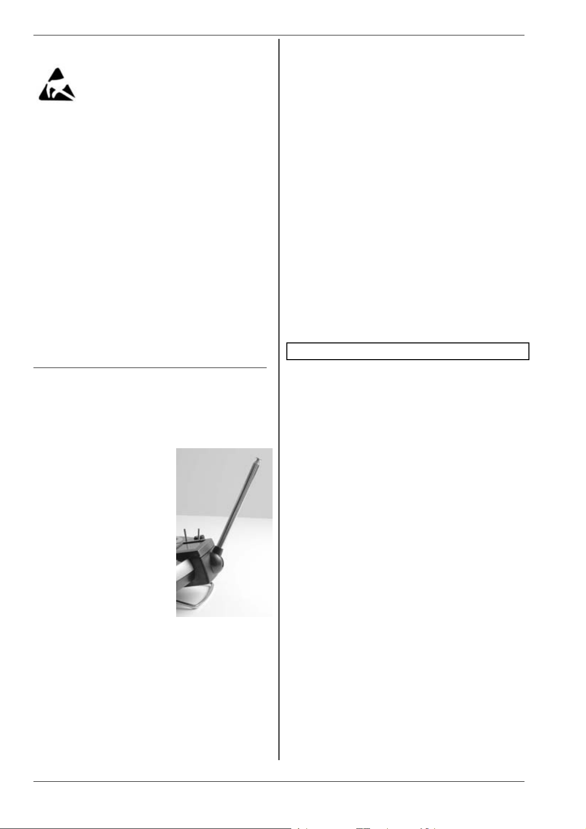
1. Move the aerial to an upright,
angled position and collapse
the segments completely
(push them together) (Î
9.5.2.).
2. Set up the model with the tip
of the receiver aerial about
1m above the ground.
3. Ensure that there are no large
metallic objects (e.g. cars,
wire fences etc.) in the vicinity of the model.
4. Do not carry out the check if
there is any other transmitter
switched on - even on a different channel.
5. The range check will not
work properly in mountainous regions.
6. Switch on the transmitter and receiver. At a range
of about 80m between transmitter and receiver
check that the control surfaces respond accurately
to the stick movements, and do not carry out any
uncontrolled movements. Close to the range limit
the servo output arms may move from their nominal position by up to the width of the arm (servo jitter).
7. Secure the model and repeat the check with the
motor running (varying the throttle setting from
idle to full-speed).
The stated range of 80m is only a general guideline. Actual range varies widely according to environmental
conditions. For example, in mountainous terrain or in
the vicinity of powerful radio transmitters, radar stations
or similar installations, effective range may only be half
that stated.
If radio range is restricted, what can you do to locate
the cause of the problem?
1. Change the position of the receiver aerial.
Metal or carbon fibre reinforced parts close by will
adversely affect reception conditions.
The effect of electric power systems and ignition
systems also alters if you change the position of the
aerial.
2. Disconnect the servos from the receiver one by one,
repeating the range check each time.
Over-long cables without suppressor filters have an
adverse effect on reception conditions. Servos also
deteriorate with age, and generate greater interference than when new (brush sparking, motor suppressor capacitors vibrated loose, general wear etc).
If you cannot effect an improvement by simple
means, try removing the complete system and operating it outside the model. This allows you to
check whether the fault is in the system, or in the
installation in the model.
4. Liability / compensation
As manufacturers, we at MULTIPLEX Modellsport GmbH
& Co. KG are not in a position to ensure that you observe the operating instructions, the conditions and
methods of installing, using, operating and maintaining
the radio control system and its components. For this
r e a s on MU L T I PLE X M o de llsp o r t Gmb H & C o. KG d e n y all
liability for loss, damages or costs which are incurred as
a result of the incorrect use and operation of the
equipment, or are connected with such use in any way.
Unless otherwise prescribed by binding law, the obligation of MULTIPLEX Modellsport GmbH & Co. KG to pay
compensation, regardless of the legal argument employed, is limited to the invoice value of that quantity of
products manufactured by MULTIPLEX Modellsport
GmbH & Co. KG which were immediately and directly
involved in the event which caused the damage. This
does not apply if MULTIPLEX Modellsport GmbH & Co.
KG is deemed to be subject to unlimited liability according to binding legal regulation on account of deliberate
or gross negligence.
Page 6
Page 8
H
ROYAL evo 7 - Instructions
5. Guarantee
We guarantee our products in accordance with currently valid legal requirements.
If you wish to make a claim under guarantee contact the
model shop from whom you purchased the equipment.
The guarantee does not cover malfunctions which are
caused by the following:
- incompetent operation,
- incorrect, neglected or postponed maintenance, or
maintenance carried out by a non-approved party,
- incorrect connections,
- the use of accessories other than genuine MULTIPLEX items,
- modifications or repairs which were not carried out
by MULTIPLEX or a MULTIPLEX Service Centre,
- accidental or deliberate damage,
- defects arising from normal wear and tear,
- operation of the equipment outside the specified
limits, or in conjunction with other makes of
equipment.
6. CE Conformity Declaration
MULTIPLEX Modellsport GmbH & Co. KG hereby declares that the ROYALevo series of equipment satisfies
the following harmonised EU directives:
Protection requirements concerning electromagnetic
compatibility
EN 300 220-3
EN 301 489-1
EN 301 489-3
Measures for the efficient use of the radio frequency
spectrum
EN 300 220-3
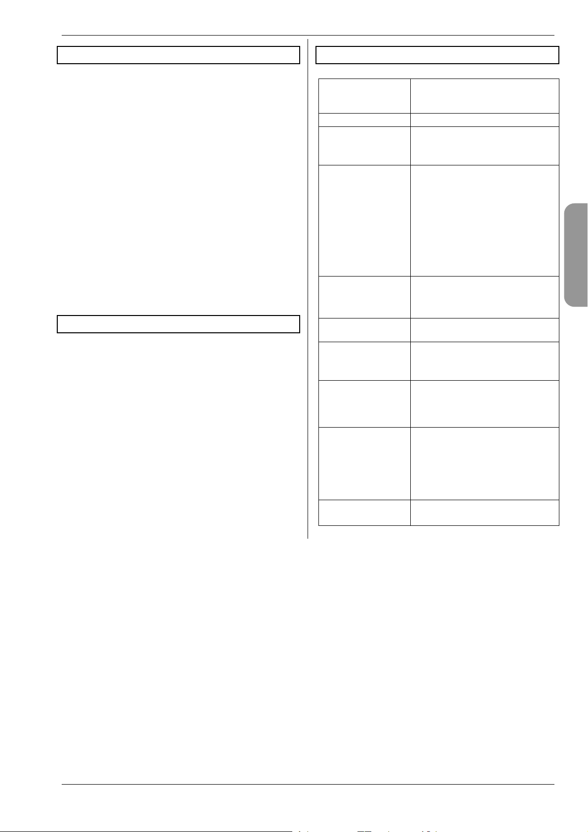
7. Specification
Channel count
(servo channels)
Model memories 15
Transmission mode
(modulation,
encoding)
Transmission rate Channel 7 not in use (PPM 6):
Servo signal format
for 100% servo
travel
Power supply 7.2 V
Current drain ~ 20 mA excl. RF module
Operating temperature range
Storage temperature range
Dimensions Length approx. 220 mm
Weight: approx. 750 g excl. battery
7
(max. 13 with MULTInaut IV expansion)
FM PPM, 10 kHz channel spacing
Automatic matching of transmission rate to servo sequence
all servo channels UNI 55.6 Hz (18
ms)
all servo channels MPX 53.8 Hz
(18.6 ms)
Channel 7 in use (PPM 7):
all servo channels UNI 49.8 Hz
(20.1 ms)
all servo channels MPX 48.1 Hz
(20.8 ms)
UNI 1.5 r 0.55 ms
MPX 1.6 r 0.55 ms
variable for each channel
(6 AA-size NiMH cells)
~ 180 mA incl. HFM-4
~ 200 mA incl. HFM-S
15qC to + 55qC
– 20° C to + 60° C
(total: approx. 250 mm
with aerial collapsed)
Width approx. 200 mm
Height approx. 60 mm excl.
sticks / support bars
approx. 900 g incl. battery
ENGLIS
Page 7
Page 9

ROYAL evo 7
8. The transmitter battery
! The transmitter battery is responsible for supplying
power to the transmitter, and plays an important
role in operational safety. For this reason please
ensure that you observe the following notes
regarding charging and maintenance of the
battery.
! The transmitter battery is fitted with a self-
resetting fuse which protects the battery itself as
well as the transmitter electronics from shortcircuit, reversed polarity and excessive currents.
Note that the transmitter circuitry features no ad-
ditional fuse! For this reason the transmitter must
always be used with a genuine MULTIPLEX trans-
mitter battery with fuse.
The ROYALevo is powered by a high-quality battery
pack consisting of six AA-size NiMH (Nickel-MetalHydride) cells. Compared to NiCd (Nickel-Cadmium)
cells NiMH batteries offer significantly higher energy
density (capacity : weight) and therefore provide longer
operating times for a given weight, but they do require
more careful handling - especially in respect of charging.
Note:
Like all other technical components, batteries are subject to constant development. We therefore reserve the
right to replace the standard transmitter pack (NiMH,
1500 mAh) with one which reflects new standards (e.g.
higher capacity).
8.1. Safety notes !
x Batteries are not playthings, and must be stored well
out of the reach of children.
x Check that the battery is in good condition before
every session. Do not continue to use a pack which is
damaged or obviously defective.
x Do not overheat, burn, open or short-circuit the bat-
tery; never charge or discharge it at excessive currents, overcharge or deep-discharge it, or charge it
with reversed polarity.
x If you charge the battery outside the transmitter,
place it on a heat-resistant, non-flammable, nonconductive surface, and do not leave it on charge unsupervised.
x Do not make modifications of any kind to the battery.
Never solder or weld directly to the cells.
x If treated incorrectly there is a risk of fire, explosion
and corrosive burns. Suitable extinguishing agents:
water, CO
x Escaped electrolyte is corrosive!
Do not allow it to contact your skin or eyes.
In an emergency wash the material off using plenty of
water, and seek medical attention without delay.
, sand.
2
8.2. Charging the transmitter battery
(slow charging)
The battery can be left in the transmitter for charging.
Basically we recommend that you recharge the battery
at the “normal” rate (1/10 C rate) overnight (e.g. plugtype 230V / 50Hz charger, # 14 5537, charge current:
150 mA). This method of charging avoids damage to the
transmitter electronics and battery, and presents fewer
problems than other methods.
! Note:
Never connect the transmitter to a charger without a
battery installed!
High output voltages may be present in battery chargers when no battery is connected. These voltages can
damage the transmitter.
How to charge the battery correctly:
1. Switch off the transmitter.
2. Connect the charge lead to the battery charger.
Note the correct polarity (!):
red plug = positive terminal (+)
blue / black plug = negative terminal (-)
Incorrect polarity will ruin the battery!
(overheating, escape of corrosive electrolyte, burst
cells)
3. Connect the charge lead to the transmitter.
Here again: check polarity carefully. Genuine MULTIPLEX transmitter charge leads are polarised
(unless you force them in the wrong way round!)
Charge process commences
4. If you use the normal or 1/10 C charge process you
must terminate the charge manually.
For a discharged battery the charge period can be
calculated using the following formula:
][ time harge
hC
Example: battery capacity 1500 mAh
”Normal charging” means that the battery is
charged at a current of 0.1 C (min. 0.05 / max. 0.2 C
= 75 mA to 300 mA).
With a charge current of 150 mA (i.e. 0.1 C) the
charge period is: (1500 mAh * 1.4) / 150 mA = 14 h.
The charge process should be terminated after this
time, if not before.
If the battery was not fully discharged beforehand,
the charge period is correspondingly shorter.
mAhC
4,1*][apacity
][ current harge
mAC
! If the battery becomes too hot to touch whilst on
charge, interrupt the charge process immediately.
5. At the end of the charge, first disconnect the
transmitter or battery from the charger, and then
disconnect the charger from the power source
(mains socket).
After the charge the battery management system may
inform you that you need to correct the battery’s state
of charge (Î 13.1.3.).
Page 8
Page 10

H
8.3. Charging the transmitter battery
(fast charging)
Fast charging is an alternative method of battery charging which is commonly employed in modelling today,
and is popular due to the reduced charge times. Fast
charging means that the battery is charged at a current
in the range 0.5 to 1 C. For a 1500 mAh battery this
means charge rates between 750 mA and 1.5 A. This
method of charging can present problems due to the
high currents, especially when charging a battery in a
radio control system transmitter, as the electronics are
liable to damage. That is why we generally recommend
the normal or 1/10 C method (Î 8.2.).
For fast charging please observe the following safety
notes:
! Fast charging should only be carried out using a
charger with a suitable automatic termination circuit.
! Time-controlled fast charging is not permissible!
! Important when fast-charging NiMH batteries:
The charger must be designed for NiMH batteries!
(Delta Peak cut-off sensitivity < 5mV / cell)
! Maximum charge current: 1.5 A!
Fast chargers must be set to manual current selection.
Don’t use an automatic program! The power circuits in
the transmitter and battery are not designed for high
currents.
If a fast charger terminates the charge process prematurely, reduce the charge current and start again.
Notes:
Reflex chargers operate with pulses of very high current
which may damage the transmitter’s electronics. If you
wish to use the reflex process, remove the battery from
the transmitter for charging.
Note that fast-charging reduces the life of the battery.
8.3.1. 12V fast chargers for up to eight cells
If you wish to use a fast charger capable of charging
only 8-cell packs (e.g. 4 - 8 cells), the battery can be left
in the transmitter. Connect the charger via the multifunction socket on the transmitter. Use the transmitter
charge lead with banana plugs, # 8 6020.
8.3.2. 12V fast chargers for more than eight cells
In this case the transmitter battery must not be
charged via the charge socket. Disconnect the pack
from the transmitter’s electronics and connect it to the
charger using the direct transmitter charge lead # 8
6021.
The battery management function of the ROYALevo (Î
8.5.) can only work properly if the electronics are
permanently connected to the battery (even when the
transmitter is switched off), and is able to measure the
currents which flow into the battery (charging) and out
of it (normal operation). Chargers designed for more
than eight cells usually incorporate voltage converters
which can generate high voltages. These excessive
voltages can damage the transmitter electronics.
ROYAL evo 7 - Instructions
FAQs
Full capacity and performance
NiMH batteries only reach their full potential after several charge / discharge cycles (~ 5 cycles). The first
charges should be made at the normal charge rate of
0.1 C (150 mA). You can then fast-charge the pack safely.
What does “C” mean in relation to charge currents?
C is the charge current at which the battery is fed 100%
of its nominal capacity when charged for one hour. For
the ROYALevo ‘s 1500 mAh battery this means a current
of 1500 mA. If this current is used for charging, we term
this a 1 C charge. This current value is simply the nominal capacity in mAh (or Ah), but with the “h” (hours) removed.
Trickle charging
This term means that the battery is charged at a current
in the range 0.03 C to 0.05 C (45 to 75 mA). Many automatic chargers switch to this mode at the end of a
charge process. The trickle charge should be terminated
after no longer than 20 hours.
8.4. Maintaining and storing
the transmitter battery
The battery’s effective capacity may be reduced if it is
stored for a long period without maintenance, or in the
wrong conditions. For this reason:
x Always store NiMH batteries fully charged. This pre-
vents the pack becoming deep-discharged (deep discharge = < 1.0 V / cell - always to be avoided).
x Charge unused NiMH packs every three months. This
compensates for the self-discharge rate, and again
avoids deep-discharging.
x Store NiMH packs at temperatures between 0°C and
30°C, in dry conditions, away from direct sunshine.
x “Balance” the battery if it has been stored for a long
period (several charge / discharge cycles at a low
charge / discharge current: approx. 1/10 C).
8.5. The ROYALevo ‘s battery management
8.5.1. What we are used to:
Voltage display
Virtually all modern transmitters display the actual battery voltage as a numerical value and/or in graphic
form.
Battery alarm
If the battery voltage falls below a minimum value, the
transmitter emits an audible alarm. Many transmitters
offer a variable alarm threshold.
Naturally, the ROYALevo includes both these functions.
The alarm threshold can also be adjusted (Î13.1.2.).
ENGLIS
Page 9
Page 11
ROYAL evo 7
8.5.2. This is NEW
The ROYALevo7’s battery management feature constantly monitors the state of charge of the transmitter
battery - even when the unit is switched off.
In detail the system works as follows:
a. when charging
If the transmitter battery is charged via the charge
socket at more than about 50 mA, the transmitter
electronics constantly measure the charge current
and calculate the charge quantity fed into the battery. This value is stored in the transmitter.
b. in use
The current is also constantly measured in use; the
transmitter calculates the consumed charge and
deducts it from the available charge. The status
display 3 (Î10.7.) then shows the available bat-
tery charge.
The transmitter also calculates and displays the re-
sidual operating time (but only when an RF signal is transmitted, otherwise the screen displays
“---“ for residual time). This value indicates how
long the transmitter can work at the present current drain.
b. Charging the battery via the charge socket
The transmitter electronics can only monitor the
state of charge if charging takes place via the
charge socket. Read the charging notes (Î 8.2.).
c. Normal charging at constant current (1/10 C)
If the battery is left connected to the charger longer
than the time calculated with the formula in Section 8.2, the battery manager still only shows a battery charge of 1500 mAh.
d. If you always charge up the battery in the transmit-
ter, and always to 100%, the displayed capacity will
remain accurate over many charge cycles. Even so,
you should check the display from time to time after charging, as inevitable tolerances may cause
deviations in the course of time.
e. If the screen shows less than 90% of the nominal
battery capacity immediately after charging, the
battery is exhausted, and should be replaced by a
new, genuine MULTIPLEX transmitter battery.
8.6. Recycling
NiMH cells do not contain environmentally harmful
cadmium, but they should still not be disposed of as ordinary household waste. Take the cells to your local recycling centre. Be sure to discharge the cells beforehand, and protect them from short-circuit (e.g. wrap
them in plastic film).
c. when the transmitter is switched off
The transmitter battery loses about 1.5% of its
charge every day through self-discharge, even
when stored unused in your workshop. The battery
management system takes self-discharge into account and corrects the displayed battery charge.
The battery charge and residual operating time are
!
only displayed for your information. Manufacturing tolerances and variations in battery maintenance can cause wide variations to occur.
8.5.3. You must take this into account
To ensure that the battery management displays values
which come as close as possible to “the true situation”,
you must observe the following points:
a. Correct the battery charge
The battery management circuit assumes that a
1500 mAh battery is installed in the transmitter. If
you fit a battery of larger capacity (for example),
you will need to enter the new capacity in the appropriate menu
Menu: L , Transmitter Parameter: Battery
charge
Here you can enter the capacity value found by
your charger (in increments of 50 mAh).
If battery voltage falls below 6.5 V, the avail-
!
able charge is set to 0 mAh.
Page 10
Page 12
H
9. The transmitter
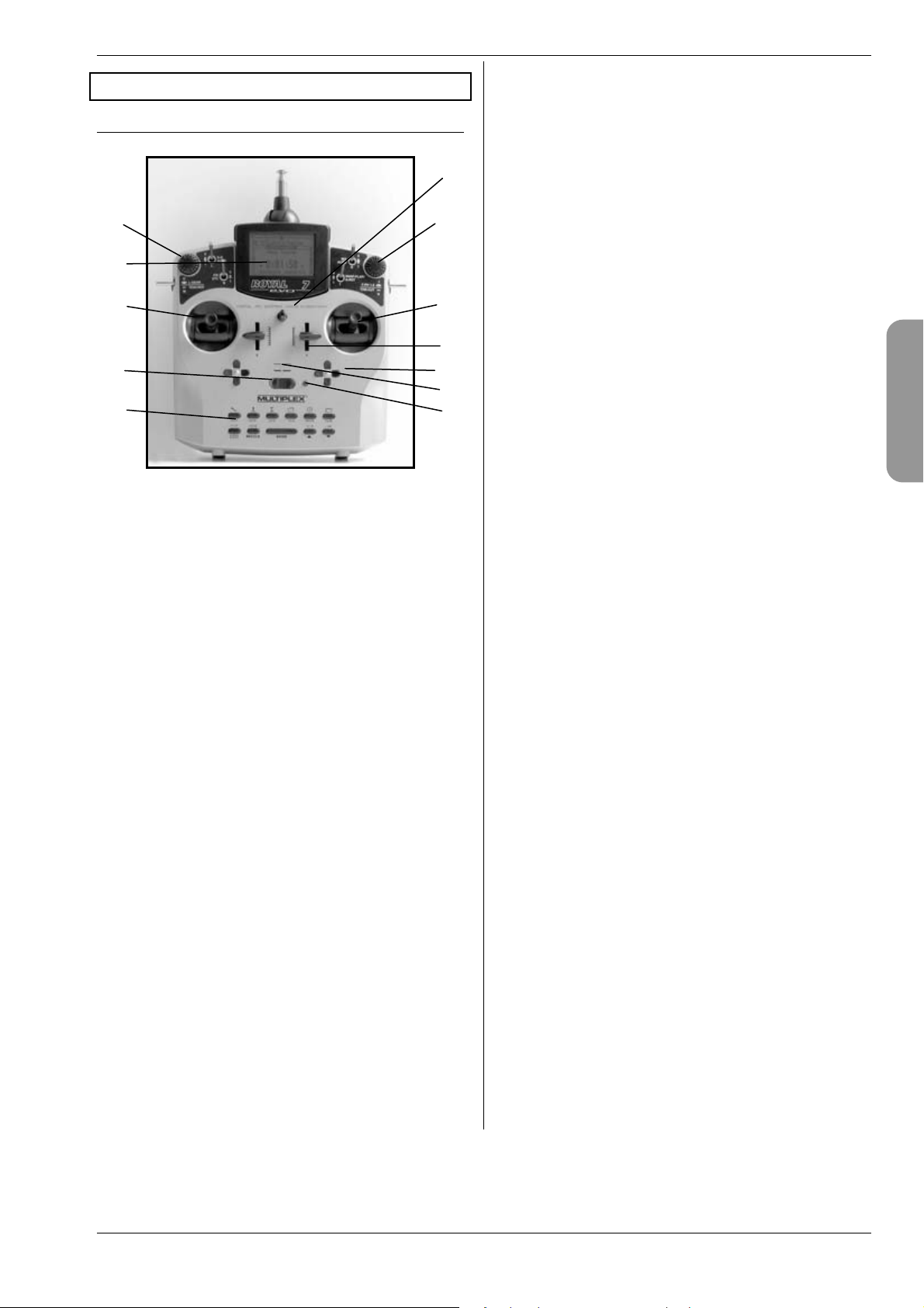
9.1. Front face of transmitter
k
j
c
l
k
c
ROYAL evo 7 - Instructions
i ON/OFF switch (“O” / “1”).
j The screen is a modern, UV-stable graphic LCD
panel (132 x 64 dots) with an anti-reflective surface.
Screen contrast is variable (Î 13.1.4.). The screen can
be tilted in two stages through a maximum of about 40°
in order to obtain the optimum viewing angle.
k Two 3D digi-adjustors are used for programming
and adjustment work. They are a standard feature, and
are permanently installed. For programming, both work
in parallel with the “ENTER” button or the “” (UP) /
“” ( D O WN) b u t t ons w h e n pre s s e d or r o t a ted. I t is po s sible to assign many different settings / parameters to
the 3D digi-adjustors, so that you can easily and directly
carry out adjustments in flight (Î 11.2.2.).
d
i
e
f
h
You will find the following controls on the front face of
the transmitter:
g
c Two precision stick units, for controlling the four
primary axes. The ratchet for the throttle / spoiler stick
can be positioned right or left (Î 9.5.6.). Both stick units
can be swivelled to suit your personal preference (Î
9.5.8.). The swivelling stick tops are infinitely adjustable
in length.
d Two sliders “E” and “F” are fitted as standard and
can be assigned to any channel. They also operate as
switched functions with centre detent.
e Two digital cruciform trim units below the stick
units for trimming the primary control axes, each consisting of one pair of buttons for left/right and up/down
(Î12.).
l Lug for connecting a neck strap
(e.g. # 8 5161 or # 8 5646).
ENGLIS
f Audible sounder (piezo beeper).
g The RF status display / LED (red light-emitting di-
ode) indicates whether an RF (Radio Frequency) signal is
being radiated when the transmitter is switched on:
LED glowing constantly o n o R F t ra ns mi ss io n
LED flashing every 2 sec. o RF transmission occurring
The LED is controlled according to the current drain of
the RF module. For example, if the transmitter crystal is
absent or faulty, no RF signal can be generated, and the
constantly glowing LED warns you that no RF signal is
being transmitted.
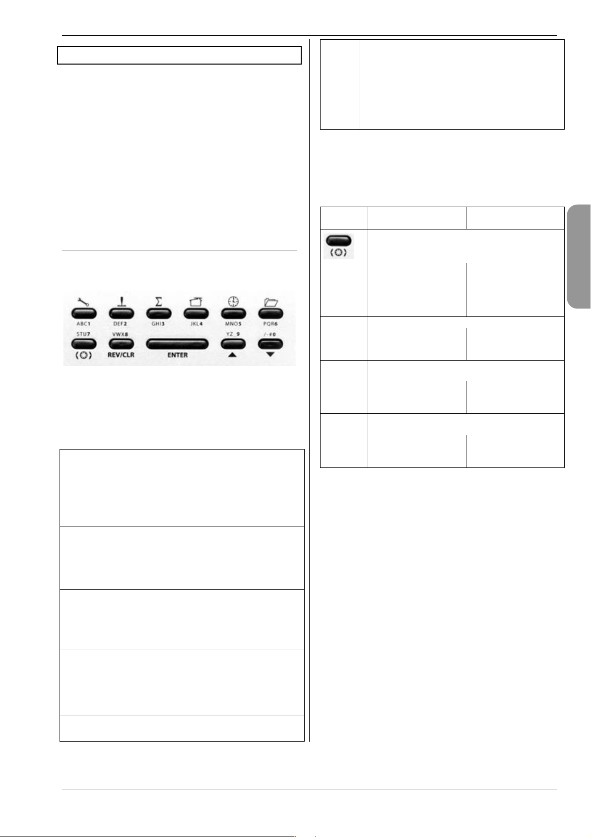
h Keypad consisting of 11 buttons in 2 rows. The six
buttons in the first row provide fast, direct access to the
6 main menus (direct menu access buttons). The 5 buttons in the second row are used for programming.
Apart from the “ENTER” button all buttons have a secondary function for entering text. Text is input using the
method commonly adopted for mobile telephones.
Page 11
Page 13
ROYAL evo 7
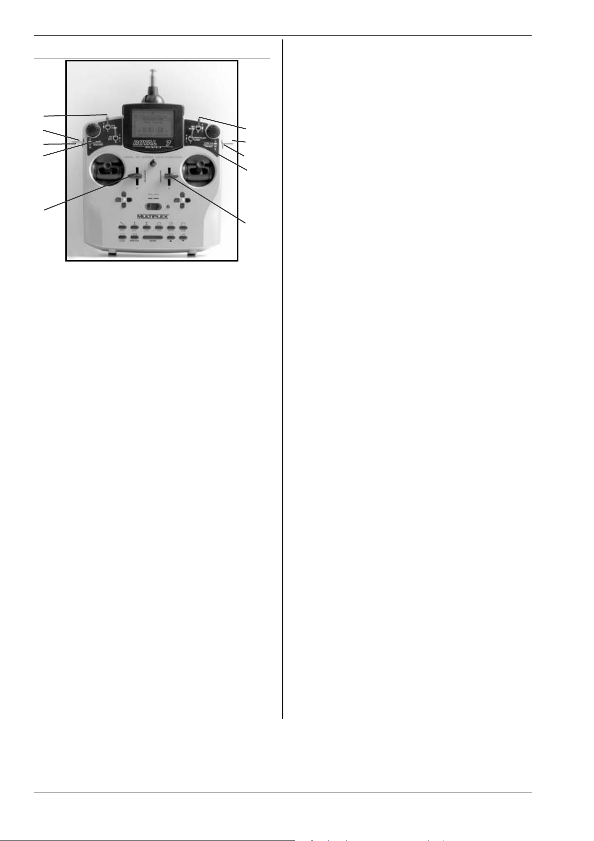
9.2. Transmitter controls
c
d
e
f
l
k
j
i
g
h
All the controls of the ROYALevo7 (6 switches, 2 buttons, 2 sliders) are permanently installed, and have the
following permanently assigned basic functions according to model type (Î 20.):
c Dual Rate (“D-R“ / 3-position switch “L“)
This switch can be used to reduce the travel - and therefore the response - of the primary controls, i.e. aileron,
elevator and rudder (heli: roll, pitch-axis, yaw) to userselectable values (Î 14.1.5.).
The 3-position switch is also used to operate the free
channel AUX 1, if it is assigned to a servo (Î 16.2.).
d Retract (“L-GEAR“ / 3-position switch “O“)
Transmitter control for the retractable undercarriage.
Requirement: “Retracts” must be assigned to a servo
(Î 16.2.).
The transit time can be extended to max. four seconds
(Î 14.1.9.).
e Trainer button (“TEACHER“ / “M“ button)
You can connect any MULTIPLEX transmitter to our
Trainer lead to act as “pupil transmitter”. You can transfer up to 5 control functions (heli: 4) to the pupil by
holding the Trainer button pressed in (Î 13.4.).
f Combi-switch (“CS“ / 2-position switch “N“)
This function is only available for fixed-wing models.
With the combi-switch you can couple the ailerons and
rudder so that the one control function follows the
movement of the other. This can make the transition
from 2-axis to “full-house” models much easier (Î
15.2.).
f Direct throttle
(“DTC“=Direct Throttle Control / 2-position switch “N“)
This function is only available for model helicopters.
Operating this switch assigns throttle control directly to
the right-hand slider (“F” = throttle limiter). This makes it
possible to control throttle using the slider F independently of the collective pitch stick, e.g. for carrying out
adjustments to the motor (Î 19.3.).
g Slider “E”
The sliders have a light ratchet effect, with a pronounced centre detent. This makes it easier to find the
centre of its travel when flying a model, without having
to look down at the transmitter.
Slider “E” controls different functions as follows:
- Power models: spoilers
- Gliders: throttle (motor)
- Helicopters: gyro
h Slider “F“
Slider “F” controls different functions as follows:
- Power models: mixture
- Gliders: flaps
- Helicopters: throttle limiter
See the model template descriptions for details of addi-
tional functions of transmitter controls “E” and “F” (Î
20.).
i Snap-flap (“SNAP-FLAP“ / 2-position switch “I“)
This function is only available for fixed-wing models.
This switch activates the “snap-flap mixer” (Î 15.4.).
i Auto-rotation (“A-ROT“ / 2-position switch “I“)
This function is only available for model helicopters.
This switch activates the “auto-rotation” flight phase
when a model helicopter is flown.
j Motor OFF button
(“THR-CUT“ = Throttle cut / button “H“)
This function is primarily intended for use with glow-
plug motors. Operating the button cuts the motor off at
any time, without having to touch the idle trim. The
throttle channel (throttle servo) stays at minimum as
long as this button is pressed in.
k Flight phase switch
(“F-PH 1-3“ / 3-position switch “J“)
This switch is use d to change from on e flight phase to
another. For this to work, the flight phases must first be
assigned. If the switch is set to a blocked flight phase,
the phase is not activated, and you will hear a constant
warning tone from the piezo sounder.
(Î 18.4.)
l MIX / AUX2 (3-position switch “G“)
Used with a glider with a four-flap wing, this switch activates the aileron Æ flap mixer. This means: the camber-changing flaps are switched to operate as secondary ailerons to support the primary aileron function
using a switchable mixer (Î 15.4.).
The 3-position switch “G” is also used as the transmitter
control for the free channel “AUX 2” for any model type.
Requirement:
“AUX 2” must be assigned to a servo.
( Î 16.2.)
Page 12
Page 14
ROYAL evo 7 - Instructions
H
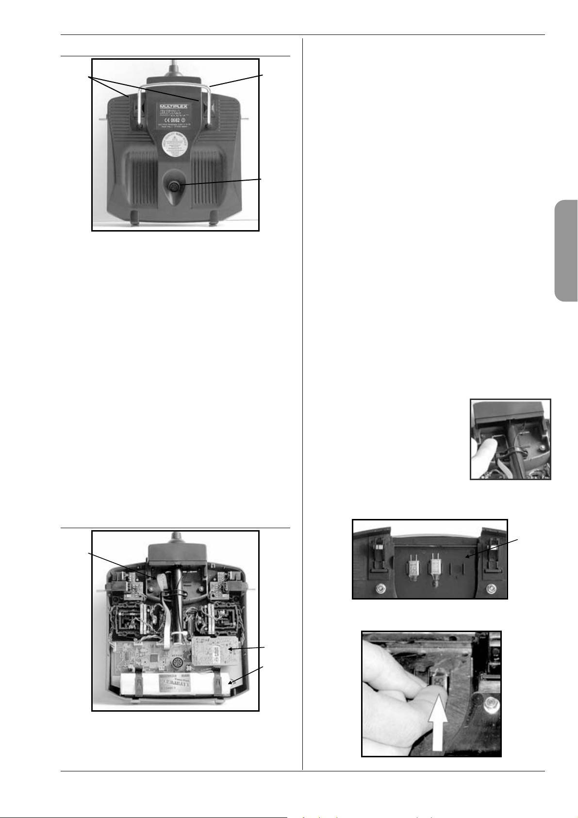
9.3. Rear face of transmitter
cd
c The transmitter battery installed as standard con-
sists of six environmentally friendly, high-capacity AAsize NiMH (Nickel-Metal-Hydride) cells. For safety reasons the cells are factory-assembled and protected in a
heat-shrink sleeve.
! Use only genuine MULTIPLEX transmitter bat-
teries! Be sure to observe the notes on battery
charging!
(Î 8.)
The transmitter battery is fitted with a special
thermo-fuse which protects the battery and - es-
e
c Two sliding latches (OPEN) allow the transmitter to
be opened and closed quickly and easily, e.g. for changing the crystal or RF module (Î 9.5.3.).
d The strong handle provides a safe method of carry-
ing the transmitter, and also protects the rear face of
the transmitter when it is placed on the ground.
e MULTIPLEX multi-function socket
As usual with MPX, the ROYALevo also features a MULTIPLEX multi-function socket (marked “CHARGE”) as
standard. It is used for the following functions:
x charging the transmitter (Î 8.)
x connecting socket for Trainer mode operations
(Î 13.4.)
x PC interface, for backing-up model data
(Î 23.1.1.)
x PC interface, for updating the transmitter
(Î 23.1.1.)
x PC interface, for use with flight simulators
x interface for diagnosis mode operations; connects to
a receiver by cable for programming and adjustment
work without transmitting an RF signal (Î 22.6.).
pecially - the transmitter from short-circuit, reversed polarity and excessive currents. The transmitter does not feature a separate fuse, and for this
reason a genuine MPX transmitter battery designed for this equipment must be always be fitted
if the pack ever needs to be replaced.
d RF module (Radio Frequency module)
The RF module is simply plugged into the main circuit
board. It can easily be changed, for example, to use a
different frequency band (Î 9.5.3.). Two different RF
modules can be used in the ROYALevo:
HFM-4:
A simple, low-cost RF module accepting plug-in crystals
for selecting the channel / transmitter frequency.
Use only genuine MULTIPLEX transmitter crystals!
The “Channel-Check“ power-on security module can be
fitted to this RF module at any time.
HFM-S:
A modern synthesizer RF module with software-
selectable channel / transmitter frequency.
A scanner with power-on guard can
be retro-fitted.
e The TORX
T6), which fits in a clip under the aerial well, is used to swivel the stick
units and similar tasks.
£
screwdriver (size
f The inside of the transmitter back panel features 3
crystal holders for spare crystals:
9.4. Inside the transmitter
ENGLIS
f
e
! Slide the crystals out - don’t lever them out!
d
c
Page 13
Page 15
ROYAL evo 7
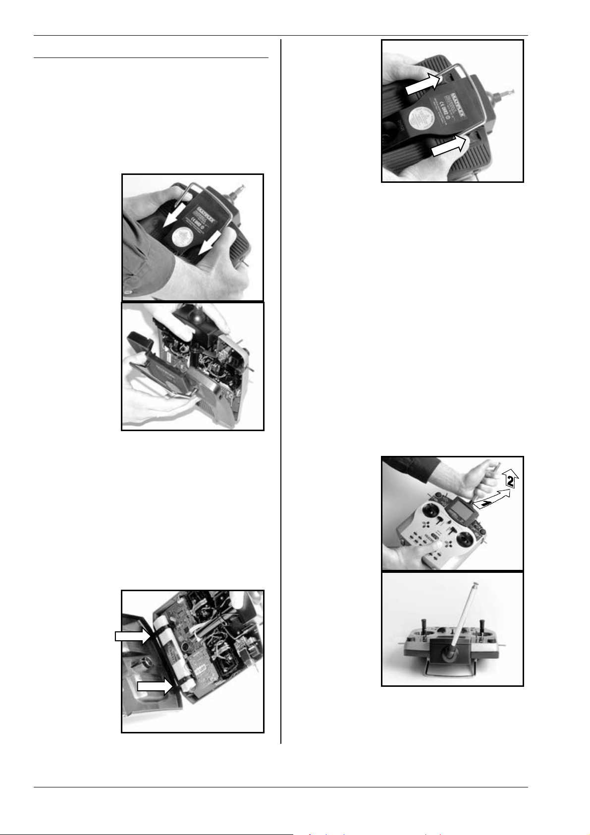
9.5. Mechanical details
9.5.1. Opening and closing the transmitter case
! Switch the transmitter OFF before opening it
(short-circuit hazard)!
Opening the transmitter case:
1. Hold the transmitter in both hands and slide both
latches on the rear face downward using your
thumbs (towards “OPEN”) (Fig. 1).
2. Carefully lift off the back panel (Fig. 2).
Fig. 1
Fig. 2
Closing the transmitter case:
1. Carefully place the bottom edge of the back panel
in the main case and check that both retaining lugs
are correctly engaged (see arrows) (Fig. 3).
2. Carefully close the transmitter back panel (Fig.
4). ! Ensure that no cables are jammed in the
joint, and that the transmitter aerial has not slipped
out of its sleeve. The back panel should fit smoothly
into place, without requiring force.
3. Slide the latches up (opposite direction to “OPEN“)
as far as they will go.
Fig. 3
Fig. 4
9.5.2. Adjusting and replacing the transmitter
aerial
The transmitter aerial is permanently fitted to the
transmitter. For transport purposes it can be collapsed
completely and recessed into the case. It can be left collapsed for set-up and programming work; this will not
harm the RF section.
! Always extend the aerial to full length before
using the transmitter to ensure reliable operation with maximum radiated power and effective range.
The aerial can be moved and locked in a second position (angled up to the left) for controlling a model:
1. Pull the aerial away from the transmitter until you
feel a noticeable resistance (Fig. 1).
2. Pull slightly harder to overcome the resistance, and
the aerial will move another 3 - 5 mm; swivel the aerial up and to the left (Fig. 2). There is now no need
to overcome the resistance.
3. Tilt the aerial as far as it will go:
the aerial locks in place.
Fig. 1
Fig. 2
To move the aerial back to its original position you must
first disengage the latch again (Î Fig. 1).
Page 14
Page 16
H
! Check regularly that the aerial makes sound
contact. Contact problems with telescopic aerials reduce radiated power and therefore effective range, and reliable operation is no longer
guaranteed. If the aerial is bent, wobbly, or excessively free-moving due to wear, you must
replace it.
If the aerial is damaged, it can easily be slid out after
removing the case back, and withdrawn from the aerial
sleeve. Fit a replacement ROYALevo aerial, # 89 3002.
The plastic guide attached to the base of the aerial
should be fitted to the new aerial; an allen key is required to remove it from the old aerial.
9.5.3. Removing and installing the RF module
The two RF modules (HFM-4 and HFM-S) are not fitted
in protective housings. For this reason:
x Avoid touching the main circuit board and its com-
ponents
x Do not stress the main circuit board
x Protect the RF module from mechanical strain
x Observe the notes regarding electro-static dis-
charge (Î 3.1.)
Do not change any settings
!
If you accidentally alter the settings of any component on the RF module, or if a component is damaged, send the module to a MULTIPLEX Service
Centre or our central Customer Service Dept. and
ask for it to be checked, repaired and re-calibrated.
Removing the RF module:
1. Switch off the transmitter!
2. Open the transmitter (Î 9.5.1.)
3. Place the transmitter face-down on a soft surface.
Take care not to damage the sticks and switches!
4. Grasp the RF module by all four corners using your
thumbs and index fingers, and withdraw it carefully
and steadily (see picture below). Keep it “square” to
its socket!
Installing the RF module:
Hold the RF module as described earlier. Ensure that the
module is engaged correctly on the contact pins. Carefully and steadily push it into place, again keeping it
“square” to the socket.
ROYAL evo 7 - Instructions
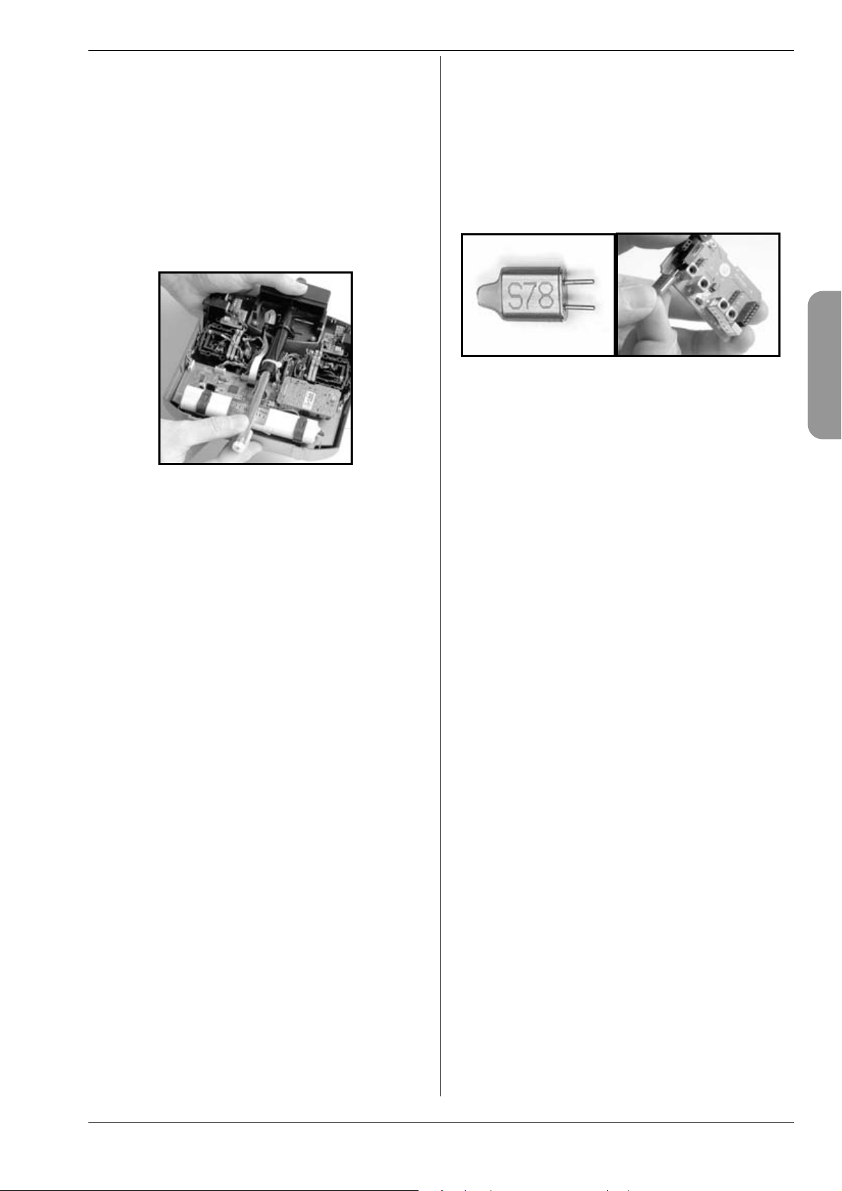
Changing the transmitter crystal (HFM-4 only)
Switch the transmitter OFF and remove the RF module.
Pull the crystal out of the RF module by its plastic tag.
When fitting the new crystal take care not to strain it
mechanically, and avoid bending the contact pins.
Use only genuine MULTIPLEX transmitter crystals designed for the frequency band of your RF module, otherwise there is no guarantee that it will work reliably.
MULTIPLEX transmitter crystals feature a translucent
blue plastic sleeve and are marked with the code letter
“S” or “Tx”.
! Crystals are extremely delicate components,
vulnerable to shock and vibration, and they are
among the parts which are crucial to the safe
operation of your RC system. Please don’t drop
them, subject them to mechanical stress (never
use force to insert them), and always store them
carefully.
ENGLIS
! When changing the RF module take particular
care to avoid touching the electronic components. If the module is to be stored outside the
transmitter, protect it from dirt and damp, and
don’t subject it to shock loads or vibration.
Page 15
Page 17
ROYAL evo 7
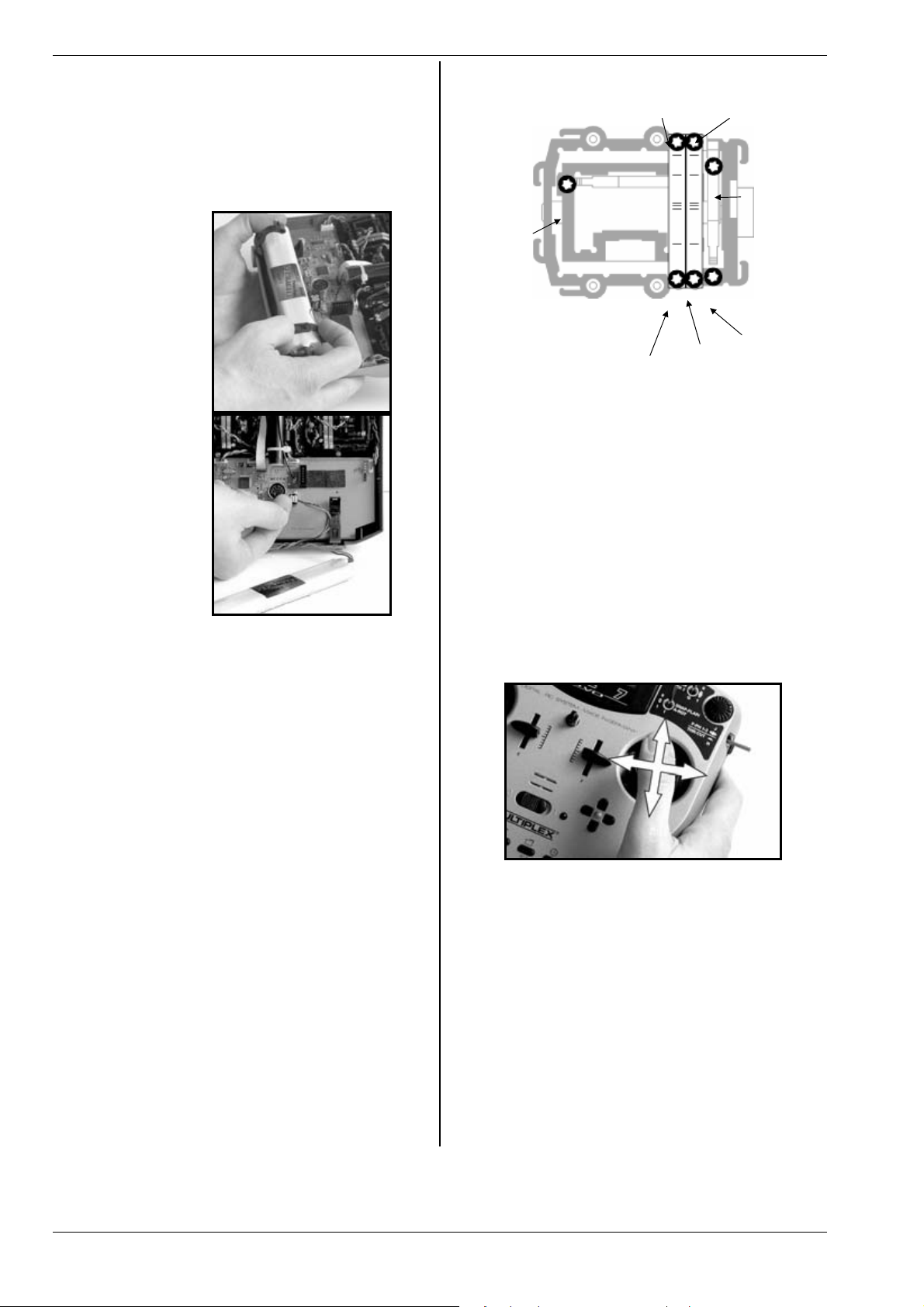
9.5.4. Replacing the transmitter battery
1. Switch the transmitter OFF!
2. Pull the snap-latches of the two plastic battery
holders back towards the battery, and fold them up
(Fig. 1).
3. Remove the battery and disconnect the battery
lead from the socket on the main circuit board (Fig.
2).
Fig. 1
(4) "Hard-
ness"
centring
force
right / left
(2) Ratchet spring for
friction brake or ratchet
(1) Disable
centring
Fig. 2
When fitting the new battery take care to stow the battery lead carefully out of the way so that it cannot get
caught up when the case is closed again.
Note:
No model data is lost when you change the battery.
9.5.5. Disabling the stick self-centring spring and
activating the ratchet / friction brake
The ROYALevo transmitter is supplied as standard with
both sticks self-centring. The springs which actuate the
ratchet or friction brake are already fitted to both stick
units, and can easily and quickly be activated:
Switch off the transmitter and open the case.
1. Locate the TORX screw for the appropriate centring
arm (1) and tighten it (clockwise) using the TORX T6
screwdriver (stored under the aerial sleeve close to
the screen) just to the point where the self-centring
action of the stick is completely disabled. Don’t
over-tighten the screw! On no account remove
the centring arm and spring!
2. The screws (2) hold the springs in place. The screws
(3) are used to adjust the hardness of the ratchet /
friction brake. The further you tighten the screw,
the harder the action of the ratchet or brake.
If you wish, it is possible to activate both springs on the
same stick, so that you obtain a mixture of ratchet and
brake action (friction) with that stick; some pilots find
this combination gives the optimum feeling of control.
(3) Strength of brake / ratchet
(4) "Hardness"
centring force
forward/back
9.5.6. Adjusting the “hardness” of the stick unit
In technical terms the “hardness” of the stick is the centring force of the neutralising spring.
With the ROYALevo it is possible to adjust the “hardness” of each of the four stick axes separately. The diagram above shows where the adjustments are made. If
you tighten the screws (4), the associated stick axis becomes “harder”.
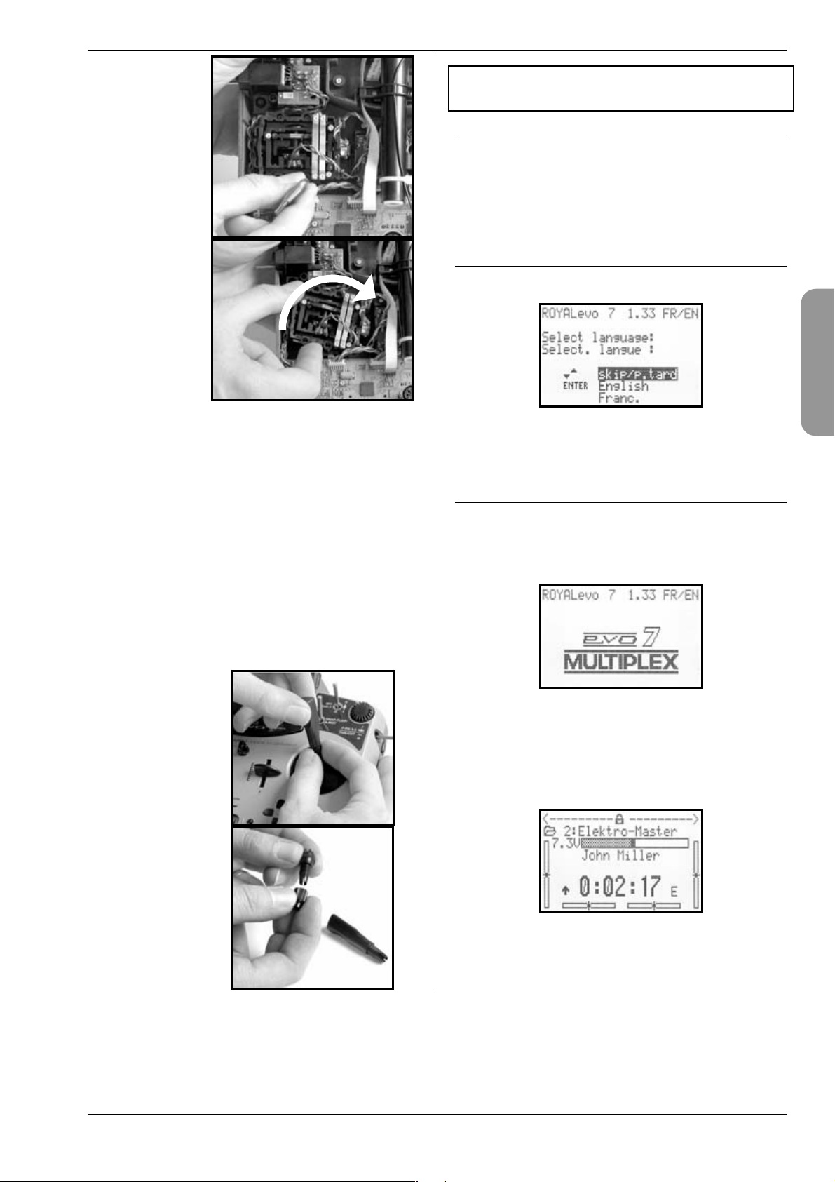
9.5.7. Swivelling the stick units
The stick units of the ROYALevo can be rotated to suit
the natural angle of movement of your hands - a unique
feature to date. This is especially useful if you use your
transmitter hand-held, and control the model using
your thumbs on short stick tops. In this case the “natural
working axis” is not exactly horizontal and vertical relative to the transmitter, but at a greater or lesser angle.
Both stick units of the ROYALevo can be swivelled to
any point up to about 15° away from “square”.
1. Locate the TORX T6 screwdriver (under the aerial
sleeve close to the screen) and use it to loosen the
three TORX screws of the appropriate stick unit to
the point where the unit can be swivelled (Fig. 1).
2. Swivel the stick unit to your preferred angle, then
re-tighten the TORX screws (Fig. 2).
! Don’t over-tighten the screws, or you risk strip-
ping the threads in the plastic!
Page 16
Page 18
H
Fig. 1
Fig. 2
10. Using the system
for the first time
10.1. Charging the transmitter battery
ROYAL evo 7 - Instructions
The ROYALevo transmitter is supplied with a partcharged battery, and it must be given a full charge before being used for the first time. Please read the charging notes carefully to avoid damaging the transmitter
battery or the transmitter (Î 8.).
10.2. Switching on for the first time
When you switch on for the first time you will see the
following screen display:
9.5.8. Adjusting and replacing the stick tops
The ROYALevo is supplied as standard with three pairs
of stick tops of different length. They are easy to
change, rotate and adjust for length:
1. Lay the transmitter on a flat surface;
2. Grasp the stick top in one hand (Fig. 1);
3. Undo the retaining nut with your other hand by
twisting it clockwise (Fig. 1).
The stick shaft is smooth, and the stick top can now be
rotated or adjusted in length. If you wish to swap the
stick tops, unscrew the retaining nuts from both stick
tops and use them to secure the replacements (Fig. 2).
Before fitting the stick tops ensure that the stick shafts
are clean and free of grease and oil. If you neglect this,
the stick tops may not stay “put” on the shafts.
Fig. 1
Use the “ “ (UP) und “ “ (DOWN) buttons to select
your preferred language, and press the “ENTER” button
to confirm your selection.
10.3. Switching on
Every time you switch the transmitter ON the power-on
info display always appears briefly. This shows information on the transmitter type, the software version and
the current national language you have selected for the
screen text displays:
If there is no RF module installed, the following message
will appear briefly:
“Attention: no RF!”
The first time you switch on, status display 1 appears;
subsequently you will see the status display 1 - 3 that
you last used:
Picture: status display 1
ENGLIS
Fig. 2
Page 17
Page 19
ROYAL evo 7
10.3.1. Switching on with the HFM-4 crystal RF
module
The power-on info display (Î 10.2.) is followed by the
status display you last used (Î 10.7.). If everything is in
order, the crystal RF module is activated and the transmitter immediately radiates an RF (Radio Frequency)
signal. The LED starts flashing (Î 10.6.), and the screen
switches to the last active status display; the transmitter
is now ready for use.
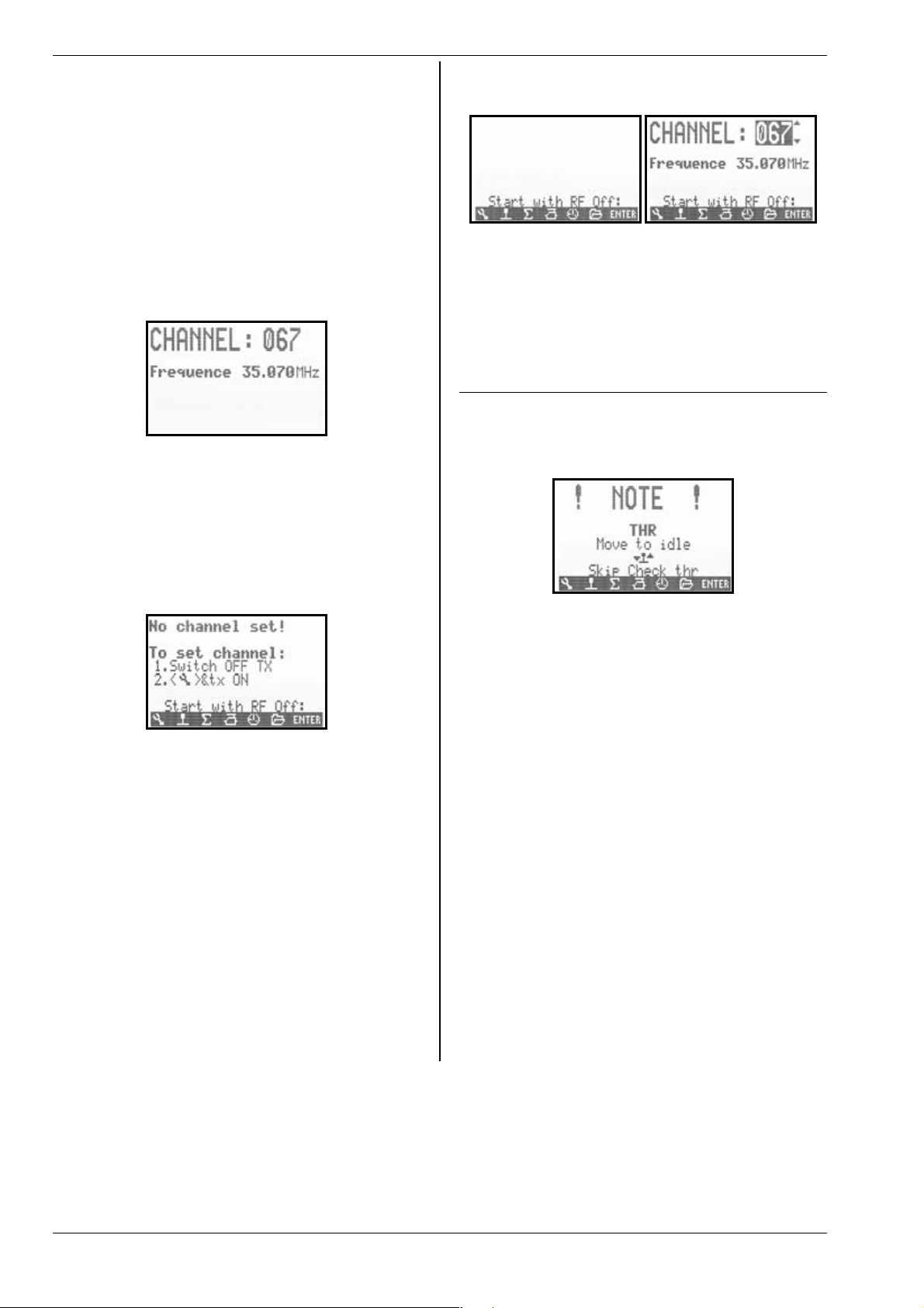
10.3.2. Switching on with the HFM-S Synthesizer
RF module
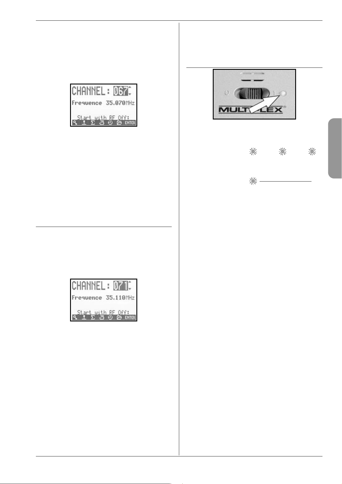
The power-on info display (Î 10.2.) is followed briefly
by a screen showing the set channel and the associated
transmission frequency:
This in turn is followed by the status display you last
used. If everything is in order, the Synthesizer RF module is activated, and the transmitter immediately radiates an RF (Radio Frequency) signal. The LED starts to
flash (Î 10.6.), the screen switches to the last active
status display, and the transmitter is ready for use.
The first time you switch on the transmitter with a Synthesizer RF module, or if you replace the Synthesizer RF
module, the power-on info screen is followed by information on how to set the transmission channel:
The method of selecting a channel using the HFM-S
Synthesizer RF module is described in the section
“Transmission channel selection with the HFM-S Synthesizer RF module” (Î 10.5.).
10.3.3. Switching on without transmitting an RF signal
It is possible to switch on the transmitter without radiating an RF signal, whether the unit is fitted with the HFM4 crystal RF module or the HFM-S Synthesizer RF module. This means that no frequency channel is used, and
the transmitter can be operated for a long period for
programming (approx. 10 x longer than when the RF
module is operating).
Hold the tool button “L” pressed in as you switch on
you are now at the power-on menu,
RF stays OFF RF status LED (Î 10.6.) glows con-
stantly.
One of the following displays appears:
With HFM-4 crystal
RF module
You can return to the last active status display by pressing any direct access menu button (one of the buttons
in the top row of the keypad) or the “ENTER” button.
With HFM-S Synthesizer
RF module
! Note:
The RF module remains switched OFF until you switch
the transmitter on again.
10.4. Security query at power-on
10.4.1. Throttle check
If the parameter Thr. check is set to ON in the menu
L Transmitter (Î 13.1.5.), the following display
may appear when you switch the transmitter on:
The transmitter is immediately ready for use; an RF signal is transmitted.
However, for safety reasons the throttle channel is
!
held at idle until the throttle control (heli: throttle
limiter) is moved to the idle position (heli: to throttle minimum).
The symbol under the message indicates the control
which operates the throttle. In the example above this is
the throttle stick. As soon as you move the throttle stick
to the idle position, the last used status display appears.
If you wish, you can switch the “Throttle Check” safety
query ON or OFF (Î 13.1.5.).
TIP:
If the throttle check display does not disappear:
This can only occur if the throttle control is faulty, you
have operated the wrong control, or you have moved it
to the wrong end-point. You can by-pass the safety
query at any time by pressing any direct access menu
button or the “ENTER” button.
Page 18
Page 20
H
10.4.2. RF check with the Synthesizer module
If the ROYALevo is fitted w ith an HF M-S Synt hesizer RF
module, you can activate an additional safety query (RF
Check Î 13.1.6.). In this case the transmitter does not
start radiating an RF signal on the displayed channel until you have confirmed this query by pressing one of the
direct access menu buttons or the “ENTER” button.
If RF Check = ON, the following display appears when
y ou sw it ch on wi th an HF M- S S yn th es iz er RF mo du le :
Line 1 shows the set channel, line 2 the corresponding
transmission frequency.
For safety reasons RF signal transmission remains
switched OFF until you confirm the displayed channel /
transmission frequency by pressing any direct access
menu button or the “ENTER” button. Only then does the
last active status display appear, and RF transmission is
activated.
The “RF Check” safety query can be switched ON or OFF
as required (Î 13.1.6.).
10.5. Transmission channel selection
with the HFM-S Synthesizer RF
module
With an HFM-S Synthesizer RF module, the channel can
be selected very simply, conveniently and safely:
1. Hold the tool button L pressed in and switch the
transmitter on
You are now at the channel set menu,
RF remains OFF (LED glows constantly)
The following display appears:
You can now select the desired channel using the “ “
(UP) / “ “ (DOWN) buttons or one of the two 3D digiadjustors. The corresponding transmission frequency is
displayed below the channel number.
2. Switch the transmitter off, then on again
(WITHOUT pressing the tool button)
The screen now displays the following:
- the number of the selected channel
- alternately:
the frequency of the selected channel
the reminder: “New channel!“
- the message: “RF activated“
- a bar display indicating the waiting period
RF signal transmission now remains switched off (LED
glowing constantly) until the waiting period (bar display) for activating the new channel has elapsed. During
this waiting period it is possible to switch off the transmitter before an RF signal is transmitted, perhaps because you have accidentally set the wrong channel.
ROYAL evo 7 - Instructions
When the waiting period has elapsed, the last used
status display appears. The RF module is activated, the
LED starts flashing, and the transmitter is ready for use.
10.6. The RF status display (red LED)
When the transmitter is switched on, the red LED (lightemitting diode) constantly indicates the current status
of t he R F mo dul e, i .e. whether an R F (R adi o Fr equency)
signal is being transmitted or not.
RF transmission ON:
The LED lights up for about 2 seconds at intervals to indicate that the transmitter is ready for use, and is radiating an RF signal.
RF transmission OFF:
The LED glows constantly.
The transmitter electronics detect whether an RF signal
is being transmitted or not from the RF module’s current drain. If the current drain falls below a certain value,
the transmitter electronics “know” that an RF signal is
not being radiated with full power, or not at all (! in
which case safe operation cannot be guaranteed). This
method of testing is very safe, as it is also capable of detecting faults and mistakes:
x Is an RF module installed in the transmitter?
x Is the RF module installed correctly in the
transmitter (contact fault)?
x Is the RF module working properly?
x Is a crystal fitted, and is it working properly
(only with the HFM-4 crystal RF module)?
x Is the transmitter aerial present, and is it mak-
ing good contact?
If the ROYALevo is in use as a pupil transmitter (Trainer
mode) or is connected for diagnosis operations, or if the
transmitter is connected to a PC, then there will also be
no RF signal transmitted LED glows constantly.
Page 19
2 sec 2 sec ...
ENGLIS
Page 21
ROYAL evo 7
10.7. The status displays
In all, three different status displays are available, designed to present relevant information while you are
flying. You can switch between the different status displays using the “ “ or “ “ buttons.
When you switch the transmitter on, the screen always
displays the status display you last used.
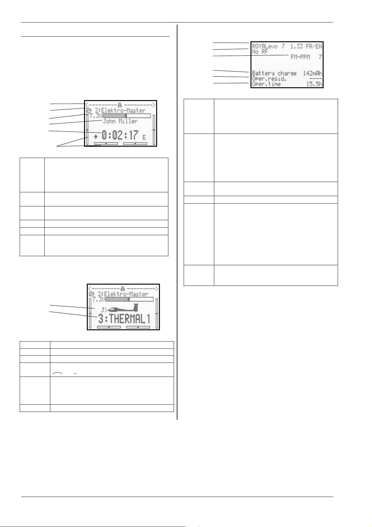
Status display
1
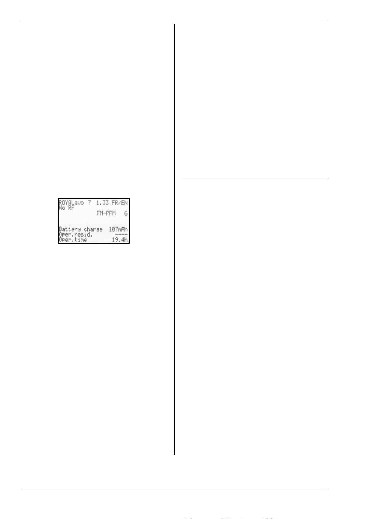
Status display 3 (system information)
1
2
3
4
5
6
1
2
3
4
5
Bars
Line 1 Status of the 3D digi-adjustors.
Numerous set-up parameters can be assigned
to the 3D digi-adjustors; they can then be
fine-tuned directly while you are flying the
model (Î 11.2.2.).
Line 2 Current model memory showing
memory number (1): model name (BASIC)
Line 3 Actual operating voltage of the transmitter
battery in Volts, and as a graphic bar display
Line 4
Line 5
Bars The four bars at the sides and bottom show
Status display
Owner’s name (Î 13.5.2.)
Display of stopwatch time (Î 10.7.)
the current trim positions for the four primary
control functions / sticks (Î 12.)
2 (flight phases)
1
2
3
4
5
Bars
Line 1
Line 2
Line 3 Transmission mode, e.g. FM-PPM 6
Line 4
Line 5 Available residual operating time
Line 6 Transmitter’s total operating time (operating
- Transmitter type (ROYALevo 7)
- Software version (e.g. V1.28)
- Language set loaded
(e.g. DE/EN, German / English) (Î 13.5.1.)
- No RF module
--> display: “No RF”
- Crystal RF module (HFM-4)
--> display: “HFM-4”
- Synthesizer RF module (HFM-S)
--> display: channel number and frequency
according to servo assignment (Î 16.2.)
Available residual battery charge (Î 8.5.)
Calculated probable residual operating time,
based on momentary current drain and displayed battery charge (line 4). This is only displayed when the RF module is active, because
the very low currents when the RF module is
not active cannot be measured with sufficient
accuracy, and thus no accurate value can be
calculated (Î 8.5.)
hours counter).
Re-starts at 0.0 h after reaching 999.9 h.
Line 1 Status of the 3D digi-adjustors; see above
Line 2 Current model memory; see above
Line 3 Actual operating voltage; see above
Line 4 Switch used to select the current flight phase
Î 18.4.)
(
Line 5
Bars Current trim positions; see above
Current flight phase (Î 18.4.) showing:
- number of flight phase (example: "3")
- name of current flight phase
(example: "Thermal 1")
Page 20
Page 22
H
11.The operating philosophy
The ROYALevo7 features a new, ultra-simple operating
philosophy, as already adopted successfully for the
ROYALevo 9 and 12. The great advantage of the system
is the clear, logically arranged list-based menu structure.
The menus and settings are displayed in plain language
(a choice of several) for ease of understanding. The system is controlled using the keypad and the two 3D digiadjustors.
The direct access menu buttons take you straight to the
clearly laid-out and logically sub-divided main menus.
Menu points can then be quickly and easily selected
and values changed using the 3D digi-adjustors (rotate
= select / change, press = confirm “ENTER”), or alternatively using UP / DOWN (“ ” / “ ”) and the “ENTER”
button.
ROYAL evo 7 - Instructions
I
11.1.2. Working buttons (row 2)
The five working buttons have different functions in the
status displays and the menus; they are shown in the
following tables.
Button Function
MEMORY ( Î 18.)
Model select (change memory)
Model copy
Model erase
Flight phase management
Model characteristics
Set up new model
Function
in the status display
in a menu
11.1. The keypad
11.1.1. Direct access menu buttons (row 1)
The keypad is used to program (more accurately: adjust
the settings of) the transmitter.
The six buttons in the top row are the direct access
menu buttons. Pressing a button takes you directly to
one of the six main menus, each of which leads to the
associated sub-menus. The buttons are marked with
corresponding symbols:
L
H
K
A
SETUP (Configuration) (Î 13.)
Transmitter
Define free mixer A/B
Assignment
Training
User
TRANSMITTER CONTROL (Î 14.)
Access to the individual transmitter control set-
up menus. Only those controls are displayed
which are used in the current model.
( dynamic menu).
MIXER ( Î 15.)
G
Access to the individual mixer menus. Only
those mixers are displayed which are used in
the current model.
( dynamic menu).
SERVO (Î 16.)
Servo calibration
Servo assignment
Servo monitor
Servo test run
TIMER (stopwatch) (Î 17.)
Open / block the pos-
sibility of changing an
assigned value. Affects both 3D digiadjustors together.
REV/CLR Reverse / Clear
All timers are reset to
ENTER ENTER
the pre-set alarm
time
No function
u p d o wn
Switch between
status displays
Digi-adjustor assign button
Select a value which
is to be altered using
one of the two 3D
digi-adjustors.
Change prefix of values (reverse), switch
function off
Activate selection,
accept values, leave
select process
UP / DOWN buttons
Select menu points
and parameters, alter
values
ENGLIS
Page 21
Page 23
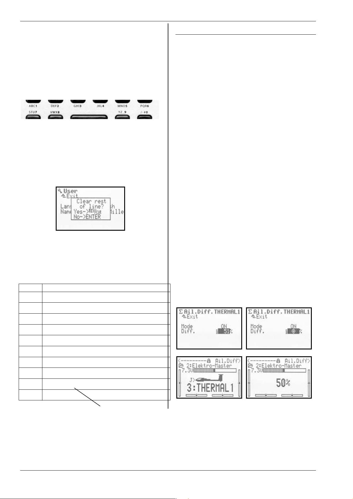
ROYAL evo 7
11.1.3. Text input
It is sometimes necessary to input text during the programming procedure, for example, in the case of model
names and the user’s name. Text is entered using the
keypad (which will be familiar to mobile phone users)
and a 3D digi-adjustor.
Letters and symbols are selected using the keypad. The
symbols which can be called up by a rapid multiple
press of one button are printed in small type below the
direct access menu buttons (row 1) and above the working buttons (row 2):
If a letter is entered at the start of a text input or after a
space, it is automatically formatted as a capital; the following letters automatically in lower case. If you wish to
enter a series of capital letters, hold the button pressed
in until the capitals appear. After the selection the input
cursor jumps automatically to the next position. The
cursor can be moved forward or back manually to any
point you wish using one of the 3D digi-adjustors.
The input process is concluded by pressing the “ENTER”
button. The screen responds with the following query:
x Pressing the “REV/CLR“ button erases all the inputs
after the last cursor position.
x Pressing “ENTER“ leaves the input unchanged.
Entering special symbols
Certain buttons can be used to enter special symbols in
addition to the printed characters.
Button Symbol
ABC1
DEF2
GHI3
JKL4
MNO5
PQR6
STU7
VWX8
YZ_9
/-#0
Space
A B C Ä 1 a b c ä
D E F 2 d e f
G H I 3 g h i
J K L 4 j k l
M N O Ö 5 m n o ö
P Q R 6 p q r
S T U Ü 7 s t u ü
V W X 8 v w x
Y Z 9 y z _ ( ) { }
0 / ? ! - + % # & < > *
11.2. The 3D digi-adjustors
Two 3D digi-adjustors (Î 9.2.) are installed in the
transmitter as standard. They are used for programming
and making adjustments.
11.2.1. Programming using the 3D digi-adjustors
During programming both 3D digi-adjustors work in
parallel with the “ENTER” button when pressed, and in
parallel with the “ “ (UP) and “ “ (DOWN) buttons
when rotated. You will quickly discover that you prefer
the one method of operation or the other.
11.2.2. Carrying out in-flight adjustments using
the 3D digi-adjustors
Many model settings can only be optimised in flight. To
this end many different parameters can be assigned to
the 3D digi-adjustors. A typical example is aileron differential.
1. Select the aileron differential parameter (Fig. 1)
2. Press the accept button < F >.
The 3D digi-adjustor symbol (Fig. 2) now appears in
place of the percentage (%) value. Now press one of
the 3D digi-adjustors to select which one you wish
to use for the in-flight adjustment.
I f y ou ma ke a m is ta ke , i .e . y ou do no t w is h t o a ss ig n
the parameter, simply press the ENTER button.
You can now leave the menu and return to the status
display.
The top line of the status displays 1 - 3 now shows that
aileron differential “Ail.Diff.” can be adjusted using the
right-hand 3D digi-adjustor (Fig. 3). If you press or rotate
the corresponding 3D digi-adjustor the current set
value of that parameter appears for a moment (Fig. 4). A
closed padlock indicates that the value cannot be altered at the moment (to guard against accidental
changes).
If you wish to be able to alter the value, press the 3D
digi-adjustor assign switch < F >: the value can now be
changed. Every alteration to the value is immediately
stored. Pressing the 3D digi-adjustor assign button
blocks access to the value again (closed padlock symbol).
Fig. 1 Fig. 2
Fig. 3 Fig. 4
Page 22
Page 24
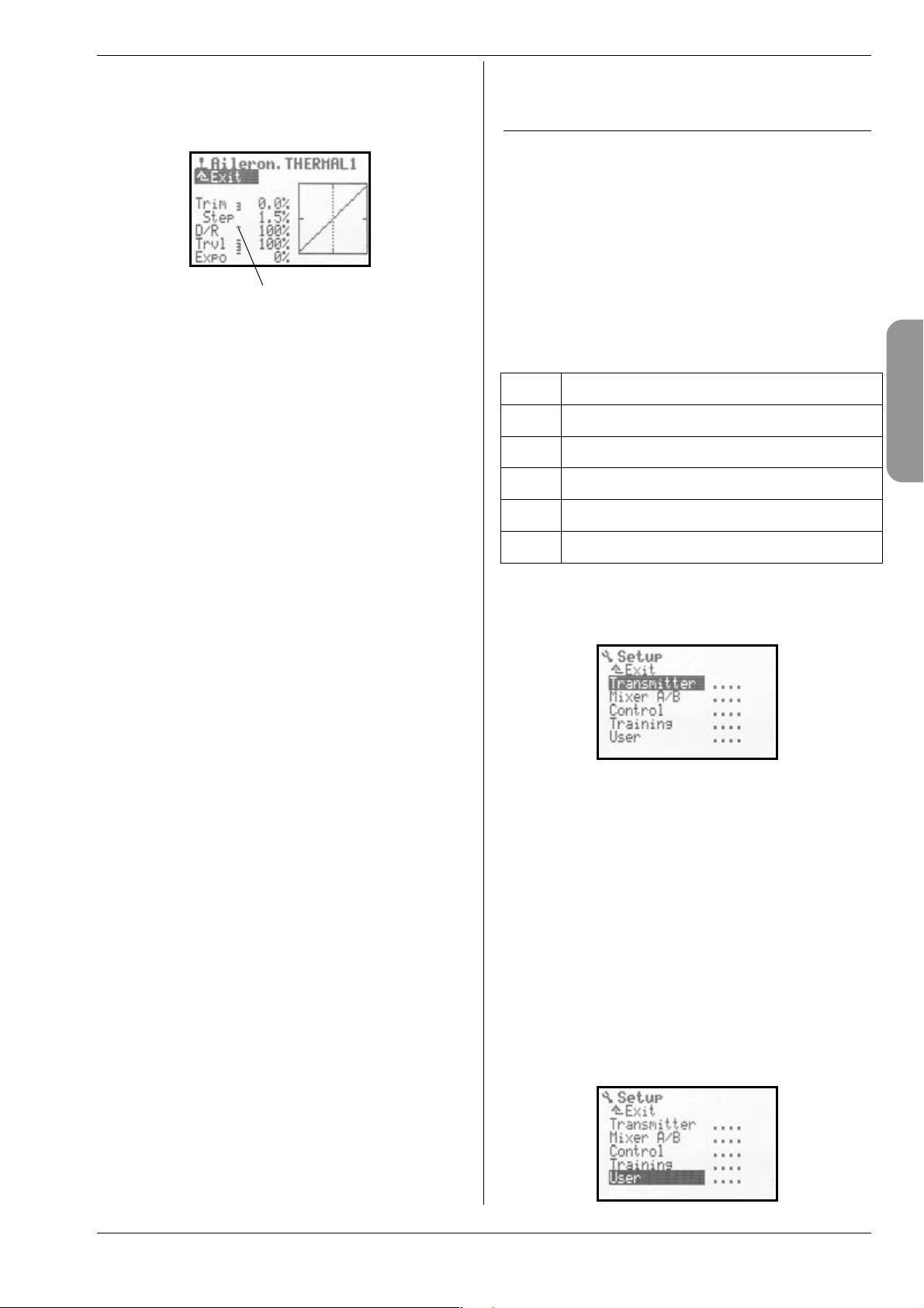
H
What can be assigned?
Virtually all parameters with numeric values can be assigned to a 3D digi-adjustor in this way, but there are a
few exceptions. In the following screen shot the “Step”
parameter (trim increment) cannot be assigned.
Assignable parameters with numeric values are indicated by a vertical hyphen after the parameter name. If
you attempt to assign a parameter which is nonassignable, this symbol appears when you press the
digi-adjustor assign button:
You will also hear an error tone when you press one of
the 3D digi-adjustors.
Erasing the assignment (sequence only)
This is the procedure for erasing the assignment:
1. Hold the corresponding 3D digi-adjustor pressed in;
2. Press the (REV/CLR) button.
the screen displays “- - -“, and the assignment is
erased.
Alternatively you can at any time “over-write” an assignment by assigning a new parameter.
Note:
To avoid the danger of making an accidental mistake,
assigned parameters cannot be reversed, i.e. it is not
possible to adjust a value past “0” or “OFF”.
Note: (sequence only)
If you are using flight phase switching
Adjustment parameters which have different values in
different flight phases are displayed according to the
currently active flight phase, and can be adjusted independently of each other from one flight phase to the
next using the appropriate 3D digi-adjustor.
ƒ
ROYAL evo 7 - Instructions
11.3. Working with the keypad and 3D
digi-adjustors - the operating philosophy
The method of switching the transmitter on has already
been described, as have the status displays (Î 10.3. /
Î 10.7.).
The following section explains the operating philosophy of the ROYALevo7 and the method of working with
the keypad and the 3D digi-adjustors, based on the example of entering the user’s name. The starting point is
one of the status displays 1 - 3 (Î 10.7.).
11.3.1. How to call up the main menus
The direct access menu buttons are the key to entering
the transmitter’s menu level for programming (Î
11.1.1.). In all six main menus are present, which contain
the following sub-menus:
L
H
K
A
I
To call up a main menu simply press the corresponding
direct access menu button.
(Example: “Input owner’s name”: button L )
The following display appears:
The first line indicates the main menu in which you are
currently working (example: Setup main menu: “L
Setup“).
The second line always shows “¨ Exit“. See:
(Î 11.3.4.) for more details.
The following lines list the associated sub-menus. The
four dots after the name of the sub-menu “....“ indi-
cate the presence of additional menus (sub-menus).
11.3.2. How to open sub-menus
You can select one of the sub-menus line by line using
the UP / DOWN buttons ( / ) or one of the two 3D
digi-adjustors. In each case the selected line is shown in
inverse video (dark background). This is similar to the
cursor on a PC.
(Example: “Enter owner’s name”: select the sub-menu
“User“).
SETUP (Configuration)
TRANSMITTER CONTROLS
MIXER
G
SERVO
TIMER (Stopwatch)
MEMORY
ENGLIS
Page 23
Page 25

ROYAL evo 7
Press the “ENTER” button or one of the 3D digi-adjustors
to open the sub-menu.
The sub-menu now opens.
(Example “Enter owner’s name”:
sub-menu “User “):
To help you remember where you are, the first line
again displays the symbol for the associated main
menu, together with the name of the currently selected
sub-menu.
(Example: switching language:
Main menu Setup: “L“ / sub-menu “ User “)
Note:
If the screen area is not sufficient to list all of the submenus, you will see arrowheads “ © “ or “ ª “ at the
edge of the screen. You can then simply “leaf through”
up or down using the UP / DOWN buttons ( / ) or
one of the two 3D digi-adjustors in order to reach the
start or end of the list. This is similar to “scrolling” in a PC
program. Example:
Press the ENTER button (or press one of the two
3D digi-adjustors) to confirm your input and leave
the input field.
Note regarding storing:
Altered values are stored immediately. It is not
necessary to store information manually.
TIP!
Using the REV/CLR button
The value of a parameter can be altered using either the
UP / DOWN buttons ( / ) or one of the two 3D digi-
adjustors. Many % values can be reversed (or reset to
the default setting) by pressing the REV/CLR button.
11.3.4. How to return
When you leave the input field, the cursor returns to the
parameter you last selected. In our example “Entering
the owner’s name” Æ Name :
11.3.3. How to change values / settings
We will enter the user’s name as our example.
Starting from the status display, this is the procedure:
1. Press the L button.
This takes you to the Setup menu. There you can
select the User sub-menu using the UP / DOWN
buttons ( / ) or one of the two 3D digiadjustors. Press ENTER (or one of the 3D digiadjustors) to move to the sub-menu.
2. Now select the Name parameter using the UP /
DOWN buttons ( / ) or one of the two 3D digiadjustors.
3. To change the settings / parameters (in our exam-
ple “Entering the user’s name” Æ Name) press the
ENTER button or one of the 3D digi-adjustors.
If you are dealing with a % value, you can now
change the selected value / parameter using the
UP / DOWN ( / ) buttons or one of the 3D digiadjustors.
In our example “Entering the owner’s name” we
will use the keypad to input text (Î 11.1.3.).
To leave the sub-menu and main menu navigate to Ҭ
Exit “ in the second line (Fig. 1) and press the ENTER
button (or one of the two 3D digi-adjustors. Repeat this
procedure until you land back at the status display.
Fig. 1 Fig. 2
TIP!
Switching directly to other main menus
If you wish to switch from any menu to another main
menu, you can do this simply by pressing the appropriate direct access menu button.
TIP!
Returning to the status display
Pressing any direct access menu button twice takes you
quickly to the status display you last used. Require-
ment: you must not be at a parameter value (in an input
field).
Page 24
Page 26

ROYAL evo 7 - Instructions
H
12.Digital trims
12.1. Introduction
The meaning of the term “trimming” is as follows:
A model aircraft is required to fly straight and level
when the transmitter sticks are left undisturbed. If this is
not the case, e.g. the model tends to turn in one direction, the neutral point of the rudder or ailerons can be
corrected (trimmed) to compensate for this.
The ROYALevo7 features a modern digital trim for all
four axes of the primary sticks.
The ROYALevo7 adopts the “Centre Trim” principle, i.e.
trim corrections only affect the central range of the
transmitter control, but not the end-points. The advantage over “standard trims” is that the full travel of the
transmitter control (and thus servo travel) can still be
exploited, as no reserve has to be provided for trimming.
Centre Trim principle
Standard
not
accessible
Bottom
end-point
trim
Untrimmed
Dead zone
Stick travel
Top
end-point
l
e
v
a
r
t
o
v
r
e
S
Trim
Standard trimming
The diagram shows that the servo reaches its top endpoint when the stick is moved to the right, but before
the stick reaches its end-point. This means: the stick has
a “dead zone”.
When the stick is moved to the left the servo never
reaches its full down-travel. This means: full servo travel
cannot be exploited.
Centre trimming
The servo reaches both its end-points, regardless of the
position of the associated trim.
TIP!
“Centre Trims” alter the response curve of the transmitter control, so you should always try to keep trim corrections to a minimum. If a major correction is required, it is
always best to adjust the mechanical linkage!
12.2. Advantages of digital trims
Digital trims have two important advantages:
1. The trim buttons have no actual mechanical position which corresponds to a trim value (cf. a conventional trim with trim sliders). The position of a
digital trim is displayed on-screen, and the trim values are stored in the model memory. If you switch
model memories, you do not need to move the
trims back to the correct position, as the correct
trim is automatically set.
2. For models which are used with flight phases, the
ROYALevo 7 provides its own trim memory for each
flight phase. Each flight phase can therefore be
trimmed accurately and simply, independently of
the other phases.
12.3. The cruciform digital trim system
The trims of the ROYAL evo take the
form of a cruciform set of buttons below and to one side of the stick units.
They are located in the ideal position in
terms of ergonomics, and are easily accessible when the transmitter is handh el d o r u se d i n a tr ay .
Every press of a trim button produces a
trim change in the corresponding control axis in the
appropriate direction. If a trim button is held pressed in
for longer than about one second, the trim automatically increments until you release the button again
(AUTO-REPEAT function).
You will hear a beep every time you generate a trim increment. If the trim reaches its centre point, or one of its
end-points, a different sound is emitted to help you
keep track of the trim position. The trim beeps can be
switched OFF and ON (Î 13.1.1.).
The trim of the fourth stick axis (‡) always af-
!
fects throttle, and takes the form of a special
idle trim.
This also applies with gliders (and powered gliders)
if this stick controls spoilers, or if it controls collective pitch on a model helicopter.
12.4. On-screen trim display
The trim settings are shown in graphic bar-graph form
on both sides and the bottom of status displays 1 - 3.
A maximum of 20 trim increments are available in both
directions, starting from the centre position. The increment size (trim change / trim step) can be set to either
of two values (0.5% / 1.5%) if required ( TStep Î
14.1.3.).
! Note: trim increment size, trim range
When you change the trim increment size, the
number of increments is unchanged; i.e. the
trim range and also the trim value (!) is altered.
This means: if you change the trim increment
size, you must re-trim your model.
The current trim value is shown on the screen in graphic
form, but can also be read off as a numerical value for
each transmitter control (Trim parameter Î 14.1.2.)
TIP! Resetting the trim to centre
If you press both trim buttons associated with a particular stick axis, the trim for the current active flight phase
is reset to centre. This also applies to the throttle trim.
Page 25
ENGLIS
Page 27

ROYAL evo 7
3.5.
13. Main menu Setup L
This main menu primarily contains settings which affect
the transmitter generally.
13.1.
13.2.
13.3.
13.4.
1
Þ This symbol indicates global settings which affect
the characteristics of the transmitter overall.
I Some settings only apply to the selected model;
they are indicated by the model memory symbol.
13.1. Sub-menu: Transmitter
13.1.1. Parameter: Sounds
Þ
The various beeps from the integral piezo sounder are
divided into five priorities. Here you can set the priority
for the audible warnings.
Setting Audible signal
1.
Batt only
2.
Trim+Batt
3.
Tr+Ti+Ba
4.
Init OFF
5.
All
13.1.2. Parameter: Battery Alarm
Þ
Range 6.70 to 7.5 V (0.01V increments)
Default 6.9 V
The battery alarm is designed to alert you when the remaining charge is only sufficient for a certain residual
operating time.
global effect
Battery alarm, error warning
Trim, battery alarm, error warning
Trim, timer, battery alarm, error
warning
Digi-adjustor, keypad, trim, timer,
battery alarm, error warning
All sounds:
Power-on tune, digi-adjustor, keypad, trim, timer, battery alarm, error
warning
global effect
This can be done by switching on the transmitter with
the aerial fully extended and an RF module installed
(crystal RF module: crystal fitted). It is not necessary to
move the sticks. Set the alarm threshold to the desired
value, and set status display 1 or 2 to show the battery
voltage.
We recommend an alarm threshold no lower than
6.90 Volts.
Now record the (warning) time from the first alarm
sound until the battery falls to the minimum operating
voltage of 6.7 Volts.
! 6.7 V is the minimum permissible operating vol-
tage.
At around 6.3 V the transmitter switches itself
off automatically!
! Caution!
The warning time is very much shorter if the
battery is already discharged to a low level
when you switch the transmitter on.
13.1.3. Parameter: Battery charge
Þ
In addition to the battery alarm (transmitter battery
voltage monitor), the ROYALevo 7 features a current
monitor. It “counts” the current which flows into the
battery when on charge, the current which flows out
when the unit is in use, and also takes into account the
self-discharge rate. From this information it calculates
the battery’s residual charge, which is displayed in
status display 3.
You can correct the calculated battery charge within the
range 0 mAh to 2500 mAh in 50 mAh increments, e.g. if
you had removed the battery for charging. The battery
charge is automatically reset to 0 mAh if battery voltage
falls below 6.5 Volts.
Pressing the “REV/CLR” button erases the displayed battery charge; pressing it a second time resets the battery
charge to 1500 mAh.
Please read the section Transmitter battery / charging
(Î 8.5.) for more information on “battery management”.
13.1.4. Parameter: Contrast
Þ
Range -8 … 0 … 8
Default 0
Altering this parameter changes the contrast of the
screen to suit the ambient temperature conditions.
global effect
global effect
! The lower the threshold you set,
the shorter the remaining residual time.
The residual operating time varies very greatly according to the condition of the battery (maintenance,
charge procedure, storage, age, number of charge cycles), as well as the set warning threshold. For this reason it is really essential that you carry out a test to establish how much residual time remains with the warning
threshold you have set.
Page 26
Page 28

ROYAL evo 7 - Instructions
H
13.1.5. Parameter: Throttle Check
I
Parameter affects the active model
only
! Guards against motors bursting into life when
the model is switched on.
Throttle Check ON
Electric-powered models may cause havoc if switched
on with full-throttle set, i.e. if the transmitter throttle
control is not at idle.
If Throttle Check = ON the transmitter checks two parameters when it is switched on:
1. Is EMERGENCY throttle CUT switched off?
2. Is the THROTTLE control at the idle position?
If the THROTTLE control is not at idle, the screen dis-
plays the following warning:
The RF module is immediately activated, but for safety
reasons the throttle signal is held at idle until the throttle control (in the illustration above the throttle stick) is
moved to the idle position.
13.1.6. Parameter: RF Check
global effect
Þ
only possible with the HFM-S Synthesizer RF module!
! Safety query when the transmitter is switched
on!
RF Check ON
Since it is relatively simple to switch channels with a
Synthesizer RF module, it is possible to activate an additional safety query with the ROYALevo7.
If RF Check = ON, the transmitter asks you each time
you switch on whether you really
channel. You have to confirm this by pressing a button:
any direct access menu button or “ENTER”). Only then is
RF transmission activated, i.e. the transmitter starts to
transmit.
wish to use the set
13.2. Sub-menu: Mixer AB
Þ Defined mixers only apply to the currently active
model. Here you can set up two different free mixers for
each model, both for fixed-wing models and helicopters.
A mixer is set up by selecting a transmitter control and a
servo (mixer: Control Æ Servo)
Press ENTER to open the appropriate input field and select a control and a servo using the ( / ) buttons or
one of the digi-adjustors. The control functions (aileron
(roll), elevator (pitch-axis), rudder (yaw), throttle) are included a second time at the end of the transmitter control list, this time without trim (e.g. Aileron-T).
The selected transmitter control is mixed into all servos
which bear the same name.
Example:
You select “L.gear” (retracts) as transmitter control, and
“V-TAIL+” as servo. The retract signal is now mixed into
both V-tail servos.
The mixer becomes active when you assign the transmitter control (in our example L.gear).
The structure of the mixer is selected in this menu point,
but the magnitude of the mixing is set in the main
menu Mixer G. It only appears if you have already “set it
up” here.
It is also possible to assign one of the mixer switches
Mix1 (= ”I”), Mix2 (= “G”) or Mix3 (= “L”). This enables you
to switch the mixer on and off in flight.
There are differences in the facilities provided by the
two mixers.
“MixerA“ features only a simple “symmetrical” travel
setting. The control functions aileron (roll), elevator
(pitch-axis), rudder (yaw), flap are mixed symmetrically,
i.e. the zero point of the mixer is the centre point of the
transmitter control. The zero point of the other control
functions is at the end of the transmitter control (neutral point of the transmitter control, e.g. throttle = idle,
collective pitch = coll. pitch min., spoiler = spoiler retracted). This mixer is designed to be used for mixing
transmitter controls whose neutral point is located at
one end-point of the control (e.g. throttle, spoiler, retracts).
“MixerB” offers separate travel adjustment for each
side of the transmitter control. This mixer is designed to
be used for mixing transmitter controls whose neutral
point is located at the centre of the control’s travel (e.g.
aileron / roll, elevator / pitch-axis, rudder / yaw, AUX1,
AUX2, collective pitch etc.).
ENGLIS
Page 27
Page 29

ROYAL evo 7
T
T
13.3. Sub-menu: Control
Fig. 1: SETUP/Control menu Fig. 2: SETUP/Control menu
for fixed-wing models for model helicopters
How do you wish to control the elevator? On the right
stick, or the left stick? Idle forward or back?
In this menu point you can select these points.
13.3.1. Parameter: Mode
I
Parameter affects the active model
only
What is known as “stick mode” determines which sticks
are assigned to the primary functions of aileron, elevator, rudder, throttle or spoiler (helicopters: roll, pitchaxis, yaw, collective pitch). All four possible stick modes
are available. The double-ended arrows are just a reminder, showing you how the sticks are assigned:
é stands for rudder or yaw
è stands for elevator or pitch-axis
hr./Sp.
Aileron
Ele.
Aileron
Thr./Sp.
Rudder
Ele.
Rudder
Pitch
Yaw
Coll. p.
Yaw
Pitch
Roll
Coll. p.
Roll
Mode
1: è é
2: é è
3: è é
4: è é
left right left right
Ele.
Rudder
Rudder
Thr./Sp.
Ele.
Aileron
hr./Sp.
Aileron
The stick mode can be changed at any time (e.g. if another user who prefers a different mode wishes to fly
your model). Switching stick modes has absolutely no
effect on other settings or values (e.g. trim settings).
The stick mode for the active model memory can be
changed both here, in the menu L Setup, Control,
and also in menu I Memory, Properties ( Î 18.5.).
Coll. p.
Roll
Pitch
Roll
Coll. p.
Yaw
Pitch
Yaw
13.3.2. Parameter: Assignment
L
Information field; cannot be modified
In the case of model helicopters (model template:
HELIccpm, HELImech), some switches and transmitter
controls are “assigned” to different functions compared
to gliders and power models. For your information this
display shows the transmitter control / switch assignment associated with the current model memory. The
assignment cannot be changed here; when you set up a
new model it is set automatically in accordance with the
selected model template.
The assignment for each model memory is displayed
both here, in the Menu L Setup, Control, and also in
the Menu I Memory, Properties ( Î 18.5.). The de-
tails of transmitter control and switch assignments
(which control / switch operates what?) can be found in
the description of the various model templates (Î 20.
on).
13.3.3. Parameter: Control neutral position
Thr. min (Idle) -->
Coll. pitch min. (negative coll.) -->
I
Parameter affects active model only
Where do you wish to have the idle setting of the throttle stick (helicopter: collective pitch minimum)? Forward
or back? The arrow (see picture) shows the current neutral position of the transmitter control. An asterisk (*) after the arrow indicates that the control is currently at
the neutral position.
To change the neutral position of the transmitter control select “Thr. min” or “Coll. min” and press the
“REV/CLR” button. The arrow now points in the opposite
direction. Press the “ENTER” button or one of the 3D
digi-adjustors to close the input field.
It is of fundamental importance to set the neutral positions of the transmitter controls correctly. Many vital
functions (e.g. idle trim, mixers, emergency throttle cut
etc.) only work properly if these settings are correct.
! Caution!
The motor may burst into life! Never change the
neutral setting of a transmitter control with the
model’s receiving system switched on.
13.3.4. Transmitter control
neutral setting parameter
Spoiler min. (Spoiler retracted) -->
Thr. limit min. (Idle) -->
Here you can select which end of the transmitter controls travel equates to spoilers retracted; helicopter:
which end-point of the helicopter control “Throttle limiter” equates to motor idle or OFF. The method of setting this parameter is described above (Î 13.3.3. and
13.3.4.).
Page 28
Page 30

H
13.4. Sub-menu: Training
13.4.1. Trainer (teacher / pupil) mode
“Trainer” mode, sometimes called the “buddy-box”
method, is the safest means of getting started in model
flying. Two transmitters are inter-connected using a
special lead. An experienced model pilot has control of
the model, but can transfer individual functions to the
pupil by operating the trainer button (“TEACHER”).
Later, when the pupil has gained some experience, the
teacher can transfer all the functions at once. If individual control functions are transferred, the teacher retains
control of the remaining functions. If he releases the
“TEACHER” button, the tutor instantly regains full control of the model, e.g. if a crash appears to be imminent.
Only the teacher’s transmitter radiates an RF signal; it
also provides power to the pupil transmitter and carries
out all the data processing, i.e. the pupil transmitter
only has to be set to pupil mode (depending on type).
No other programming is necessary, and no settings
have to be altered. All the teacher’s transmitter requires
from the pupil transmitter is the pure stick signals.
The ROYALevo7 can be used both as teacher and pupil
transmitter.
As teacher transmitter the ROYALevo7 can transfer up
to 5 functions to the pupil.
With a fixed-wing model these are:
Aileron, elevator, rudder, throttle, spoiler
With a model helicopter:
Roll, pitch-axis, yaw, collective pitch
As pupil transmitter the ROYALevo7 generates the
same functions as listed above, which can be accepted
by the teacher transmitter. If the ROYALevo7 is set to
pupil mode, the trims, mixers and all transmitter control
and servo settings are switched off.
13.4.2. The ROYALevo as teacher transmitter
1. Connect the teacher and pupil transmitters using
the Trainer lead, # 8 5121, connected to the multifunction sockets. Take care to connect the cable
correctly: the pupil end of the lead is marked
“Schüler” (pupil), the teacher end “Lehrer”
(teacher).
The following transmitters can be used as the pupil
unit: ROYALevo7 / 9 / 12, Cockpit MM, Commander
mc, EUROPA mc, PiCOline, PROFI mc 3010 / 3030 /
4000.
Many older models of MULTIPLEX transmitter are
also suitable for use as pupil transmitters. If your
pupil transmitter is not listed above, please check
with our Customer Services Department.
2. Now switch on the teacher transmitter
(ROYALevo7) this automatically switches on the
pupil transmitter, which is powered by the teacher
transmitter.
Important: the ON/OFF switch on the pupil transmitter must be left at the OFF position!
ROYAL evo 7 - Instructions
3. Move to the Setup / Training sub-menu.
You will see the following display:
Fig. 1: SETUP / Training menu Fig. 2: SETUP / Training menu
for fixed-wing models for model helicopters
The “<M” display means that the button on the left-
hand side (<) of the transmitter is the one used to
transfer control (the Trainer switch). If you operate
this button, an asterisk (*) appears to indicate that
the pupil can control the model.
4. Select:
Mode = Teacher M, if the pupil transmitter generates signals in the MULTIPLEX format
(neutral pulse width = 1.6 ms)
(e.g. ROYALevo 7 / 9 / 12 with “Train M”, Cockpit
MM with servo format setting to “M”, Commander
mc, EUROPA mc, PiCOline, PROFI mc 3010 / 3030 /
4000).
Mode = Teacher U, if the pupil transmitter gener-
ates signals in the UNIVERSAL format.
(Neutral pulse width = 1.5 ms)
(e.g. PiCO-line, ROYALevo transmitter with "Train
U", COCKPIT MM with servo format setting to "U"
(UNI).
5. Select the function which the pupil is to control,
and press the “ENTER” button or one of the 3D
digi-adjustors.
The cursor is now located at the input field for
channel assignment.
6. On the pupil transmitter move the transmitter control with which the pilot is to control the selected
control function (Quick-Select). The corresponding
channel number is displayed (e.g. “Ch1” for aileron). Check that the model’s control surfaces move
in the correct “sense” (direction). If not, you can reverse the function by pressing the REV/CLR button
(# or ').
Note: Quick-Select can only be used if the
ROYALevo7 is switched on and radiating an RF
signal.
7. Press the “ENTER” button or one of the 3D digiadjustors to complete the assignment process.
Hold the “TEACHER” button pressed in to check
that the system is working correctly. The pupil pilot
should now operate the control function you have
just assigned. Check that the control surfaces on
the model work in the correct direction!
8. Repeat steps 5. to 7. until all the control functions
which are to be transferred to the pupil have been
assigned. You can then return to the status display
and start the training session.
ENGLIS
Page 29
Page 31

ROYAL evo 7
Take care when assigning the throttle or collec-
!
tive pitch control functions, as the motor could
burst into life! Injury hazard!
E n s u r e t h a t n o b o d y i s i n d a n g e r o f i n j u r y i f a m o t o r
revs up or bursts into life, and that the model is not
able to cause other damage. For safety reasons the
assignment should be made with the motor
stopped or the electric motor disconnected. You
can check that the system is working as required
by using the servo monitor facility even with the
model switched off (Î 16.3.) .
An assignment can be erased by selecting the control
function and selecting “OFF” using the ( / ) buttons
or one of the digi-adjustors.
If the transmitter is switched off in “TeacherU” or
“TeacherM” mode, the transmitter will automatically
switch to the Setup / Training menu when next
switched on, and remind you that the transmitter is operating in this mode.
13.4.3. The ROYALevo as pupil transmitter
Important: if the ROYALevo is used as a pupil transmit-
ter, the trims have no effect (teacher’s trims active).
The following can be used as Teacher transmitters:
ROYALevo 7 / 9 / 12, Commander mc, PROFI mc 3010 /
3030 / 4000.
Some older MULTIPLEX transmitters are also suitable for
use as teacher transmitters. If your teacher transmitter is
not listed above, please enquire at our Customer Service Department.
1. Connect the pupil transmitter to the teacher
transmitter using the Trainer lead, # 8 5121, connected to the multi-function sockets. Take care to
connect the cable correctly: the pupil end of the
lead is marked "Schüler" (pupil), the teacher end
"Lehrer" (teacher).
2. Now switch on the teacher transmitter.
The pupil transmitter (ROYALevo7) is automati-
cally switched on, and draws power from the
teacher transmitter.
3. Switch to the Training sub-menu.
4. Select:
Mode = Pupil M, if the teacher transmitter expects
signals in the MULTIPLEX format.
(Neutral pulse width = 1.6 ms)
(e.g. ROYALevo 7 / 9 / 12 with “Teacher M”, Commander mc, PROFI mc 3010 / 3030 / 4000).
Mode = Pupil U, if the teacher transmitter expects
signals in the UNIVERSAL format.
(Neutral pulse width = 1.5 ms)
(e.g. ROYALevo 7 / 9 / 12 with “Teacher U”)
The following display now appears:
Note:
If the ROYALevo7 is switched off again after a training
session without the Training / Mode parameter being set to OFF, for safety reasons the transmitter
switches directly to the SETUP / Training menu
when next switched on.
Before every flight in Trainer mode be sure to check
the following points one last time:
x Are all the control functions which the pupil is not
permitted to control set to “OFF”?
x Is the assignment of the control functions unam-
biguous? It is not permissible for any of the pupil’s
servo channels to be assigned twice!
x Are all the directions of rotation of the control func-
tions correct? Please check this every time before you
fly the model.
Note:
If the cable connection between the two transmitters is
disconnected during a Trainer session, all control functions automatically revert to the teacher’s transmitter.
13.5. Sub-menu: User
13.5.1. Parameter: Language
Þ
The ROYALevo7 features two language sets for the
screen texts. By default English (main language) and
German are installed (language set: EN/DE). In the L,
User menu you can switch between these two languages using the Language parameter.
On the Internet we will be making additional language
sets available for downloading; please visit the
download area of our website
http://www.multiplexrc.de/
PC program ROYALevo-DataManager there, which is
required to install these files in your transmitter. To connect the transmitter to your PC you will need the PC interface lead, # 8 5156. (Î 23.).
13.5.2. Parameter: Name
Þ
In this field you can enter your own name (user name)
of up to 16 characters. The text is entered using the
method described in the section “Text input” (Î
11.1.3.). Your name then appears in status display 1 (Î
10.7.). The default name is “MULTIPLEX”.
global effect
. You can also download the
global effect
Page 30
Page 32

H
14. Main menu Control H
The term transmitter control refers to all the elements
of the transmitter to which control functions are assigned. They may be sticks, sliders or switches.
The Control menu is dynamic, i.e. it only shows those
controls which are used for the currently active model.
All other controls are suppressed, in order to prevent
confusion caused by unnecessary information. For a
simple fixed-wing model or helicopter the Control
main menu may look like this:
Overview of controls and available parameters
The following table provides an overview of all transmitter controls, in each case with all available parameters. The controls are arranged according to fixedwing models and helicopters. Some controls may appear in fixed-wing and helicopters. Controls which have
the same parameters are assembled in groups.
Where you see the symbol after an available parameter, this means that the value may be different in all
flight phases.
for fixed-wing model aircraft
Control Parameter Note Section
Aileron
Elevator
Rudder
Throttle
Spoiler
Flap
Trim
Step
D/R
Travel
Expo
Idle Display of ideal setting
Step
Slow
Slow
Fixed values
Display of trim position
in %
Digital trim increment
0.5% / 1.5%
Dual Rate (switchable
control travel)
0% to 100%
Travel adjustment,
0% to 100%
Exponential control
effect
-100% to +100%
Digital trim increment
0.5% / 1.5%
Slow function (speed
setting) for throttle
0.0 to 4.0 sec.
Slow function
(speed setting)
0.0 to 4.0 sec.
Flight phase dependent
fixed value setting for
the transmitter control
OFF, -100% to +100%
14.1.2.
14.1.3.
14.1.5.
14.1.6.
14.1.7.
14.1.4.
14.1.3.
14.1.9.
14.1.9
14.1.8
ROYAL evo 7 - Instructions
for model helicopters
Control Parameter Note Section
Display of trim position
in %
Digital trim increment
0.5% / 1.5%
Dual Rate
(Switchable travel)
0% to 100%
Travel adjustment
0% to 100%
Exponential
control effect
-100% to +100%
6-point coll. pitch curve
coll. pitch values:
P1...P6: -100% to +100%
Throttle min. (idle)
0% to 100%
5-point throttle curve
P1...P5: 0% to 100%
Flight phase dependent
fixed value setting for
speed controller
OFF, -100% to +100%.
Fixed values for the
speed controller are
switched off using
switch G
Roll
Pitch axis
Yaw
Coll. p.
Throttle
RPM
Thr. limit
Trim
Step
D/R
Travel
Expo
P1...P6
Min.
P1...P5
Fixed
values
– No adjustments
for fixed-wing models and helicopters
Control Parameter Note Section
Slow function
L. gear
Slow
(speed setting)
0.0 to 4.0 sec
Aero-tow
Brake
Gyro
– No adjustments
Mixture
AUX 1
AUX 2
– No adjustments
14.1.2
14.1.3
14.1.5
14.1.6
14.1.7
14.1.10
14.1.12
14.1.11
14.1.8
14.1.9.
ENGLIS
Page 31
Page 33

ROYAL evo 7
14.1. Screen structure of control menus
Our example shows the screen display for the aileron
control, with all the available set-up parameters. The
display may not look exactly like this as it depends upon
the transmitter control and its available parameters.
The screen is divided into three sections:
1. Name of control and active flight phase
At the top is the name of the transmitter control (in
our example Aileron). Next to it is the name of
the active flight phase (in our example the NORMAL
flight phase).
2. Parameter list
On the left you see all the parameters of the transmitter control you have selected together with the
set values, all clearly laid out.
3. Graph
The graph on the right displays the effect of all the
settings in graphic form. The curve of the graph
immediately reflects changes in the settings and
makes the behaviour of the control easier to understand. The dotted vertical line shows the current position of the transmitter control.
Next to the parameters you will see two additional indicators:
The small, high-set dash following the parameter name
indicates that this value can be assigned to one of the
3 D d i g i -adju s t o r s , a nd ca n t h en be ad ju st ed in f l i g h t (Î
11.2.2.).
Expo — -90%
The small number after the parameter name (1 to 4) indicates that this parameter can be set to a different
value for each flight phase (Î 18.4).
14.3. Parameter: Step (trim increment)
for controls:
for controls:
Adjust. range 1.5% (= normal) / 0.5% (= fine)
The digital trims of the ROYALevo7 have a trim range of
±20 increments. With Step you can determine the trim
change in % trim increment. The maximum trim range is
±10% when Step is 0.5%, and ±30% when Step is
1.5%.
Note
!
If you change the increment size and one transmitter control trim is already off-centre, the actual trim
setting will change. In this case you must adjust
the trim setting to obtain the original deflection.
In most cases a trim increment of 1.5% proves to be
ideal. However, for very fast models with precision control linkages, and models with very large control surface
travels (e.g. fun-fly models) the 1.5% trim increment
may be excessive. In this case you should set Step to
0.5%, as this provides ultra-fine trim control.
Aileron, elevator, rudder, throttle
Roll, pitch-axis, yaw
14.4. Parameter: Idle (idle trim)
For control: Throttle
1
Idle trim is necessary for models powered by internal
combustion motors. The motor is required to run at a
safe idle when the throttle stick (throttle control) is at
the idle end-point. The throttle trim can be adjusted at
any time to set and adjust the idle speed. The trim for
the throttle control therefore only affects the bottom
half of the travel, i.e. from idle to half-throttle.
Display only
Trim ˜ 2.0%
Some parameters can be assigned to the 3D digiadjustor and also be changed separately for each flight
phase. In this case both symbols are displayed.
Trvl – -90%
14.2. Parameter: Trim
for controls:
for controls:
1
The positional display of the digital trim takes the form
of a bar graph in status displays 1 and 2 (Î 10.7.). The
Trim parameter also shows the trim setting of the
transmitter control in each flight phase as a % value.
Aileron, elevator, rudder
Roll, pitch-axis, yaw
Display only
One trim value for each flight phase
The neutral (idle) position of the throttle control is selected at the Thr. min parameter in the Setup /
Control menu (Î 13.3.3.).
Like Trim, the Idlel parameter only provides informa-
tion, and shows the idle setting in %. The idle setting is
displayed in graphic form in status displays 1 and 2.
Page 32
Page 34

H
14.5. Parameter: D/R (Dual Rate)
for controls:
for controls:
Adjust. range 10% to 100%
F
Dual Rates are designed to modify the sensitivity of a
transmitter control. For example, if the Dual Rate parameter for a control function such as aileron is set to
50%, you can reduce the model’s aileron travel to 50%
by operating the “D-R” switch (= L), and thereby obtain
finer aileron control. The control curve in the graph alters appropriately when you operate the “D-R” switch.
Aileron, elevator, rudder
Roll, pitch axis, yaw
Can be assigned to a 3D digi-adjustor
(Î 11.2.2.)
14.6. Parameter: Travel
for controls:
for controls:
Adjust. range 0% to 100%
F
The Travel parameter offers the same facility as Dual
Rates: the sensitivity of a transmitter control can be
modified (reduced). The difference with Travel is that
the effect can vary from one flight phase to another, i.e.
you can set a different value in each flight phase. For
example, in the “NORMAL” flight phase = 100% for
maximum control response; in the “SPEED” flight phase
= 70% for finer control.
Note:
At any one time only one value can be displayed for the
act i ve fli ght p h ase. If yo u wish t o cha nge t h e val ues fo r
other flight phases, make sure that you select the appropriate flight phase before you change the setting.
Aileron, elevator, rudder
Roll, pitch-axis, yaw
One value for each flight phase
Can be assigned to a 3D digi-adjustor
(Î 11.2.2.)
14.7. Parameter: Expo
for controls:
for controls:
Adjust. range -100% to +100%
F
Expo can be used to modify the effect of the transmitter control in the area around centre. At Expo = 0%
the control’s response is linear. The effect of negative
Expo values is that a command generates small control
surface travels in the area around centre, giving the pilot finer control. This is the most common application
for exponential (Fig. 1).
Aileron, elevator, rudder
Roll, pitch-axis, yaw
Can be assigned to a 3D digi-adjustor
(Î 11.2.2.)
ROYAL evo 7 - Instructions
The effect of positive Expo values is to increase control
surface travels around neutral. The model is “sharper” in
response. Expo does not affect the servo end-points, i.e.
full travel is still available if necessary.
Fig. 1 Fig. 2
14.8. Parameter: Fixed values
for controls:
Adjust. range -100%...OFF...+100%
F
With this parameter you can generate fixed control surface travels for each flight phase, which cannot then be
changed by the associated transmitter control. If Fixed
value is set to OFF, the transmitter control operates
the control surface in the normal way.
A typical example is the thermal and speed settings on
a four-flap glider (e.g. F3B). For example, if you activate
the THERMAL flight phase, the ailerons and camberchanging flaps move to a new neutral position optimised for thermalling (e.g. thermal flap, fixed value = 30%). If fixed value is set to OFF for the NORMAL flight
phase, the neutral position of the ailerons and flaps is
infinitely variable using the flap control when you select
the Normal flight phase.
Note:
At any one time only one value can be displayed for the
act i ve fli ght p h ase. If yo u wish t o cha nge t h e val ues fo r
other flight phases, make sure that you select the appropriate flight phase before you change the setting.
Spoiler, flap
One value for each flight phase
Can be assigned to a 3D digi-adjustor
(Î 11.2.2.)
14.9. Parameter: Slow (speed)
for controls:
for controls:
Adjust. range 0.1 to 4.0 s
F
The Slow parameter can be used to alter the time over
which the transmitter control moves the servo from one
end-point to the other. The usual application for this is
to slow down a process which is operated by a switch.
Examples:
Retracts: extend slowly, so that the undercarriage retract sequence looks true to scale.
Spoiler (airbrakes): extend slowly, so that the model
does not carry out any jerky movements when the
brakes are deployed.
Page 33
Throttle, spoiler, flap, retracts
Retracts
Can be assigned to a 3D digi-adjustor
(Î 11.2.2.)
ENGLIS
Page 35

ROYAL evo 7
14.10. Parameter: Coll. P. P1...P6
(collective pitch curve)
for control:
Adjust. range
F
The collective pitch curve for model helicopters is set up
in the menu H Control / Coll.P. For each flight
phase a separate collective pitch curve can be set up in
the ROYALevo7, each with six curve points P1...P6, so
that the best possible match of collective pitch control
can be o bta ine d for each fl igh t ph ase . As an aid to set ting up, a vertical dotted line appears in the graph of
the curve showing the current position of the collective
pitch stick.
Example 1: Collective pitch curve, flight phase HOVER
A “flatter” collective pitch curve from hover collective /
stick centre to min. collective / descent is intended to
provide finer control at the hover and at touch-down.
Collective pitch
-100%...OFF...+100%
for all curve points P1...P6
Separate curve for each flight phase
Curve points can be assigned to a 3D
digi-adjustor (Î 11.2.2.)
14.11. Parameter: Throttle P1...P5
(throttle curve)
for control:
Adjust. range
F
The throttle curve for model helicopters is set up in
menu H Control / Throttle. For each flight phase
(F-PH 1-3) a separate 5-point throttle curve can be set, in
order to obtain the best possible matching of motor
power to the collective pitch curve setting for the flight
phase in question. The aim is to achieve a constant system rotational speed over the entire range of collective
pitch. The throttle curve can only be fine-tuned accurately when the model is in flight, as it varies according
to many parameters (motor power, motor setting,
power characteristics, collective pitch curve, rotor
blades installed, etc.). If any one parameter is changed,
the throttle curve generally needs to be adjusted anew.
As an aid to setting up, a vertical dotted line appears in
the graph of the curve showing the current position of
the collective pitch stick.
Example 1: Throttle curve, flight phase HOVER
Collective pitch
0% (= OFF) ...100% (= full-throttle)
for all curve points P1...P5
0% (= motor OFF) ...100%
for Min. (= idle)
Separate curve for P1...P5 for each
flight phase
Curve points P1...P5 can be as-
signed to a 3D digi-adjustor
(Î 11.2.2.)
Example 2: Collective pitch curve, flight phase CRUISE
Linear, symmetrical collective pitch curve for constant
collective pitch control in climb and descent modes.
Overall higher max. collective pitch values, as generally
a higher system speed is set (throttle curve), so that
higher rates of climb are possible.
For the first time the ROYALevo includes a 6-point collective pitch curve. The advantage, especially for modern, high-power 3-D helicopters with a broad collective
pitch range (up to r 10...12q), is the ability to set “plateaux” in the “normal” and “inverted” areas, giving fine
control at the hover.
Example:
Simple throttle curve for the hover. At negative collective
pitch (= descent) least motor power is required (in our example P1 = 35%). At positive collective pitch (= climb) maximum
power is required (in our example P5 = 85%).
Example 2: Throttle curve, flight phase 3D
Symmetrical, V-shaped throttle curve, opens the throt-
tle setting when climbing either upright or inverted.
Note:
It is only ever possible to display the collective pitch
curve for the active flight phase. If you wish to make
changes to a collective pitch curve, ensure that you first
set the desired flight phase.
Page 34
Page 36

H
Special case (throttle curve OFF)
Electric helicopter, e.g. with brushless motor and speed
controller in regulator (governor) mode.
In this case there is no need to set up a throttle curve in
the transmitter. The speed controller, when set to regulator mode, provides a constant system rotational
speed. All it requires is a fixed value for the required system speed in each flight phase. The throttle curve can
be switched off in the menu Memory / Properties
/ Throttle curve (Î 18.5.4.). P1...P5 then
automatically have the same value (= fixed value), regardless of the point being adjusted.
ROYAL evo 7 - Instructions
14.12. Parameter: Thr. Min.
(idle, throttle limiter)
The parameter Min. determines the idle speed of the
power system when the throttle limiter is set to minimum or idle (Î 13.3.4. Setup / Control / Throttle limit
min). In glow-powered models this is the speed required for starting the motor and a safe idle (approx.
20%). For electric-powered models this is set to -% =
motor OFF. This parameter takes effect in all flight
phases, and can be adjusted if required using the idle
trim (trim buttons for the collective pitch stick) (Ú).
The horizontal dotted line in the graph shows the position of the throttle limiter in all flight phases. The throttle limiter limits the throttle setting, i.e. it never permits
a higher throttle value under any circumstances than is
set for the throttle limiter.
Throttle curve AUTOROT (auto-rotation)
The fourth flight phase with model helicopters is autorotation (AUTOROT = emergency landing after motor
failure). This always has highest priority of all flight
phases. This means: if you operate the “A-ROT” switch (=
I), the transmitter switches to the auto-rotation flight
phase regardless of the position of the flight phase
switch “F-PH 1-3” (= J). The throttle setting for autorotation is not a curve, but a fixed value. This permits a
fixed throttle setting (e.g. reliable idle with glow motors
/ motor OFF with electric motors). The auto-rotation
flight phase is primarily used for practising autorotation landings.
Points P1 ... P5 cannot be set separately. Changing one
value forces a change to all points. The fixed autorotation throttle value is reduced or increased. Example:
Note:
It is only ever possible to display the throttle curve for
the active flight phase. If you wish to make changes to a
throttle curve, ensure that you first set the desired flight
phase.
TIP:
To set the idle (Min. parameter) move the throttle limiter to the idle setting. The change in idle Min. can then
be seen directly from the horizontal dotted line for the
throttle limiter.
ENGLIS
Page 35
Page 37

ROYAL evo 7
15. Main menu Mixer G
In the main menu Mixer you can set up all the mixers
required for your model. The Mixer main menu is a
dynamic menu, i.e. in the interests of clarity only those
mixers are shown which are used in the current model.
Fixed-wing models
The mixers V-tail, CombiSwitch and Ail.Diff (ai-
leron differential) are always present.
The following mixers may also appear, depending on
the model template you have selected:
ELEVATR+, V-tail+, DELTA+, AILERON+, FLAP+
For a model based on the ACRO model template the
Mixer main menu may look like this:
Model helicopters
Helicopters always feature the TAIL mixer (static tail
rotor compensation). For helicopters with electronic
swashplate mixing (CCPM) the Rotor head mixer also
appears when the HELIccpm model template is in use.
Fixed-wing models and helicopters
If free mixers are required for additional mixed functions, they may be defined in the Setup / MixerAB
menu for both fixed-wing models and helicopters (Î
13.2.). These free mixers can also be set up in the Mixer
main menu, where they appear as MixerA and Mix-
erB (Fig. 1).
15.1. Mixer: V-tail
Adjust. range ON, OFF
If your model has a V-tail, switch the V-tail mixer ON.
The Mixer main menu now automatically includes the
mixer V-TAIL+. If the mixer ELEVATR+ was already
present, it is now replaced by V-TAIL+.
In the “Servo Assignment List” (Î 16.2.) the servos
Rudder and Elevator or ELEVATR+ are replaced by
V-TAIL+.
If you switch off the V-tail mixer again, the previous
state is restored.
Direction of rotation and travel for the mixer inputs are
adjusted in the V-TAIL+ mixer.
for fixed-wing models only
15.2. Mixer: CombiSwitch
I Aileron Î rudder (aileron is Master) 2% to 200 %
Aileron Í rudder (rudder is Master) -2% to -200%
2% increments, switchable
Adjust. range
Switch CS/DTC (<N)
F
Smooth, constant turns can only be achieved with coordinated use of ailerons and rudder - this applies to
full-size aircraft and models alike. This is not easy, especially for the inexperienced pilot. The combi-switch
couples the ailerons and rudder, making it simpler to
perform turns when making the transition from simple
rudder-elevator models to the more demanding “fullhouse” model aircraft (aileron / elevator / rudder).
fixed-wing models only
2% to 200 %
Aileron Î Rudder (aileron is Master)
-2% to -200%
Aileron Í rudder (rudder is Master)
“Following” value can be assigned to
a 3D digi-adjustor
( Î 11.2.2.)
F ig . 1 F ig . 2
If you wish, the CombiSwitch mixer can be switched
on (= 1) or off (= 0) at any time using the switch
“CS/DTC” (<N). The arrow Ð on the screen indicates that
the combi-switch is ON at the “down” position. If the
switch is at the ON position, this is indicated by an asterisk () after the arrow.
Page 36
Page 38

H
In the bottom line you can set the “following” value (2%
to 200%). The direction of following is determined by
the prefix to the value. In most cases the rudder “follows” the aileron (aileron = Master). In this case a positive prefix (+) needs to be set. If you set a following
value of 100%, full aileron movement produces full rudder movement. If you set a value of 200%, full rudder
travel is reached when aileron travel is only half of full.
15.3. Mixer: Ail.Diff
Adjust. range
F
A simplified description of aileron differential:
If aileron travel is the same up and down (symmetrical
movements), the down-going aileron (on the outside of
the turn) generates greater drag than the up-going aileron on the inside of the turn. The result is an unwanted moment (adverse yaw) which tends to rotate
the model away from the turn. The model yaws in the
opposite direction to the turn.
Differential aileron travel reduces the adverse yaw by
reducing the travel of the down-going aileron. Note
that differential travel is only possible if separate servos
are used for each aileron. 100% differential is also possible: in this case only the up-going aileron moves (“split”
mode).
Differential aileron travel is not necessary for highspeed power models with symmetrical-section wings.
Gliders with heavily cambered wings are the usual candidate, and a differential rate of around 50% is generally
a good starting point with such models, although the
optimum value can only be found by flight-testing. The
greater the camber of the wing section, the more differential is required. For this reason it is possible to set different rates of differential in each flight phase.
Example - glider and flight phases:
NORMAL: Ail.Diff=50%
THERMAL*: Ail.Diff=65%
SPEED**: Ail.Diff=40%
* Ailerons (and camber-changing flaps, if fitted) are deflected down slightly for thermal flying
=> greater airfoil camber
=> more aileron differential required
** Ailerons (and camber-changing flaps, if fitted) are deflected up slightly for speed flying
=> reduced airfoil camber
=> less aileron differential required
fixed-wing models only
Diff.: -100% ... OFF ... 100%
Prefix (+/-) reverses direction
=> reduces up or down aileron travel
Separate differential value (Differ.)
can be set for each flight phase
Differential value (Differ.) can be
assigned to a 3D digi-adjustor
(Î 11.2.2. )
ROYAL evo 7 - Instructions
15.3.1. Parameter: Mode
The Mode parameter is used to activate the Ail.Diff
mixer (ON) or switch it off (OFF).
If bot h aileron s of your m ode l can also be raised to a ct
as a landing aid, you should choose the SPOILER
mode. This means that differential aileron travel is suppressed when the landing aid is deployed (using the
“spoiler” transmitter control). The effect is that more aileron response is available on the landing approach, as
the aileron travels are not reduced.
15.3.2. Parameter: Diff.
This is where you set the differential value. If the differential travel is the wrong way round (up-aileron movement reduced), simply reverse the value (“REV/CLR” button).
Aileron differential can be varied separately for each
flight phase. To set the value, activate the appropriate
flight phase using the flight phase switch “F-PH 1-3” (>J)
(the active flight phase is shown in the top line, and indicated by the number preceding the parameter), and
set the appropriate value for Diff..
ENGLIS
Page 37
Page 39

ROYAL evo 7
15.4. The "...+" mixers
Adjust. range
F
The ROYALevo7 offers what we call “…+” mixers for all
fixed-wing model templates. These are specially
matched to suit the model template, and cover all relevant mixer functions.
The following mixers are available:
ELEVATOR+
V-TAIL+
DELTA+
AILERON+
FLAP+
Which “…+” mixers are available in the various model
templates, and how each mixer works in detail, is described in detail in the Model Template sections (Î 20.).
The Mixer main menu is a dynamic menu, i.e. only
those mixers are displayed which are actually used on
the model in question.
15.4.1. How the “...+” mixers work
The “…+” mixers work in the same way as the freely definable 5-way mixers of the ROYALevo 9 / 12. The basic
principle is the proven one adopted in the MULTIPLEX
PROFI mc 3000 and 4000 series of radio control systems.
It can easily be described in the following way:
Always start from the “control functions”, or the movements of a servo. Example: aileron servo in a model
glider (example AILERON+ mixer):
Under which circumstances should this servo (or these
servos) move?
1. When the “aileron” control is operated (primary
function)
2. When the “spoiler” control is operated
(large up-movement of ailerons as landing aid)
for fixed-wing models only
-100% ... OFF ... 100%
All mixer settings can be assigned to a
3D digi-adjustor
(Î 11.2.2.)
Mixer for elevator, with compensating
inputs for:
spoilers (airbrakes), flaps, throttle
(motor)
Mixer for V-tail, with compensating
inputs for:
spoilers (airbrakes), flaps, throttle
(motor)
Mixer for deltas and flying wings with
compensation for throttle (motor)
Mixer for models with two aileron
servos with the following inputs:
spoilers (ailerons as landing aid), flaps
(ailerons used to alter wing camber),
elevator (to support the elevator
function)
Mixer for camber-changing flap servos on four-flap glider wings, with the
following inputs:
spoilers (flaps as landing aid), flaps
(flaps used to alter wing camber), elevator (to support the elevator function)
3. When the “flap” control is operated
(slight up / down aileron travel to alter the wing
camber for thermal and speed flying)
4. When the “elevator” control is operated
(up/down aileron travel to support elevator re-
sponse in aerobatics snap-flaps)
From this it is clear that the aileron servos are actually
controlled by four transmitter controls. The AILERON+
mixer therefore has four inputs (up to 5 inputs are possible):
The mixer adds together the values / signals of the individual inputs (thus the sum symbol £) and passes on
the result to the aileron servos (AILERON+).
1
5
TIP:
For MULTIPLEX PROFI mc 3000 / 4000 connoisseurs:
On the ROYALevo7 the mixer inputs are set at the
mixer, rather than at the servos.
Advantage:
The mixer inputs are set up at one point in the Mixer
menu, rather than at several (servos). The set-up process
is therefore simpler and less time-consuming. This
change also makes it simple to assign the input value to
a 3D digi-adjustor for convenient in-flight adjustment.
This does make it important to calibrate the servos carefully (Î 16.1.), otherwise it is not guaranteed that a
model, for example with ailerons deflected up for the
landing, will fly straight on the approach, because the
travel of the ailerons may not be identical.
15.4.2. How to set up “...+” mixers
Note: first calibrate the servos, then set up the mixer (Î
16.1.)!
Fig. 1
Fig. 2
Ex.: AILERON+ mixer
Fig. 3
Mixer inputs
Mixer values
Page 38
Page 40

H
Fig. 4
Dynamic overwriting:
Mixer value(s)
Mixer option (symbol)
The “…+” mixer is set up in the main menu Mixer after
calling up a “…+” mixer (AILERON+ in our example ).
The mixer is then displayed, complete with all mixer inputs (Figs. 2 - 4).
What does the menu show? (Figs. 2 - 4)
Mixer inputs
The bottom five lines list the mixer inputs, i.e. the
transmitter controls which influence the movement of
the control surface in question.
Mixer values
The two columns to the right of the inputs show the
value for each mixer input (one or two values, depending on the mixer option of each mixer input). In this
menu only the displayed values can be altered.
Select the input to be changed. Press ENTER to move to
the first mixer value, which can then be altered. Pressing
ENTER again takes you to the second mixer value. Pressing ENTER once more concludes the adjustment process
for that mixer input.
“Dynamic overwriting”
Line 3 of the menu displays “dynamic” superimposed
information, depending on the mixer input at which the
cursor is currently located. This explains the current
mixer option in the form of a symbol, and the type of
mixer value.
Mixer switch
Column 4 indicates whether the mixer input in question
is switchable. If so, the switch and its current status are
displayed (example: I
Ð):
* (asterisk) Mixer input = ON
Ð (arrow) Shows the ON position of the switch,
if the switch is in the OFF position
15.4.3. Mixer options
“Symmetrical”
™
Neutral control setting: Centre
One parameter: Travels
-100%
Servo travel
100%
-100%
100%
Trv
Control
The control produces
symmetrical servo
movement with variable travel.
Typical application:
aileron input in
travel
AILERON+ mixer
ROYAL evo 7 - Instructions
“Asymmetrical“
š
Neutral control setting: Centre
Two parameters: TravelÏ and TravelÐ
Servo travel
100%
-100%
Trv#
œ
-100%
“Single-sided, with curve “
Trv'
100%
The control produces
asymmetric servo
movement. The servo
travels can be set to
different values for
Control
each direction.
travel
Typical application:
flap input in
LERON+
Neutral control setting: End-point
Two parameters: Pnt1 Point1, Pnt2 Point 2
-100%
›+
Servo travel
100%
Pt2
Pt1
Control
100%
-100%
“Single-sided / linear with offset“
The control produces
servo movement starting from the end-point
of the control, with 2
points at ½ and full
control travel.
travel
Typical application:
compensation input,
e.g. spoiler to ELE+
Neutral control setting: End-point
Two parameters: Offset and travel
-100%
Offs
Servo travel
100%
Offs = 0%
Offs = -50%
-100%
Trv
100%
The control produces
linear servo move-ment
from its neutral position, which can be
shifted using Offset.
Control
Typical application:
travel
spoiler input in
/ AILERON+
for large down-travels
when butterfly / crow
braking is deployed.
15.5. The MixerA/B free mixers
Adjust. range
F
The free mixers (MixerA/B) can be used for special
mixer functions which are not covered by the “…+”
mixers. These two mixers are available for any model
(every model template), and are defined in the menu
Setup / MixerA/B, after which they appear auto-
matically in the current model in the
where they then have to be activated and set up to suit
your specific application.
Page 39
for fixed-wing models and helicopters
-100% ... OFF ... 100%
All mixer set-up values can be as-
signed to a 3D digi-adjustor
(Î 11.2.2.)
Mixer main menu,
AI-
mixer
ENGLIS
FLAP+
mixer,
Page 41

ROYAL evo 7
15.5.1. Free mixer MixerA
This mixer mixes one control function (transmitter control) into one or more servos carrying out the same task.
The zero point of many control functions (transmitter
controls) is in the centre; in the case of others it is at one
end of the transmitter control’s travel. We have taken
this into account with this mixer. For aileron/roll, elevator/pitch axis, rudder/yaw, AUX1, AUX2 and collective
pitch the mixer’s zero point lies at the centre of the
transmitter control. With the other control functions it is
at one end-point. You should select this mixer when
you need to mix transmitter controls whose neutral
point is not in the centre, e.g. throttle, spoiler, retracts, ...
Travel parameter
At this point you enter the magnitude and direction of
effect of the mixer (in our example: mixed elevator as
compensation when landing gear is extended).
If the neutral position of the mixed transmitter control is
at one of the two end-points, the mixing only occurs in
one direction, starting from the servo’s centre setting.
If the neutral position of the transmitter control is in the
centre, mixing occurs in both directions.
15.5.2. Free mixer
MixerB
This mixer mixes one control function (transmitter control) into one or more servos carrying out the same task.
There are two travel settings: one for each side of the
transmitter control.
Example: snap-flaps (elevator Æ aileron)
Travel+ , Travel- parameters
At this point you adjust the travels and direction of effect of the transmitter control to suit the servo travel. In
our example Elevator --> aileron Travel+ produces an
aileron servo movement of 20% when you apply upelevator stick (stick back), and 30% when you apply
down-elevator (stick forward).
Both mixers can be switched off using one switch (Mix1
= I, Mix2 = G, Mix3 = L), provided that you assigned a
mixer switch when defining the mixer. In our example
“snap-flaps” this is the mixer switch Mix2 (G>). The arrow
Ð indicates the switch position at which the mixer is
s w i t che d o f f. If a n a ster i s k appears, the switch is at its
ON position, and the mixer is active.
15.6. Mixer: Gyro
The gyro mixer of the ROYALevo7 can be used both
for fixed-wing model aircraft and helicopters, provided
that the gyro you are using features an input for remote
gain adjustment (by radio). The
the optimum gain setting to suit each flight situation.
The main menu
interests of clarity mixers which are not required for the
current model are not displayed on-screen. If the
mixer is to appear in the
function must be assigned to one servo channel in the
menu
Servo / Assignment ( Î 16.2.).
The design of the gyro mixer of the ROYALevo is entirely
new. It permits optimum stabilisation of one model axis
both with simple gyros and modern heading-hold gyro
systems, regardless of gyro type and installation. To
achieve this the gyro mixer of the ROYALevo7 offers
several different operating modes. We recommend that
you start with the
good chance to become familiar with the basic functions (Î 15.6.1.).
The following table shows the basic types together with
the properties of standard commercial gyro systems.
Damping gyro
(standard gyro)
The gyro damps the rota-
tional movement of a
model around the
stabilised axis.
Gyro gain adjustment over
the range 0 ... 100%:
for fixed-wing models and helicopters
gyro mixer provides
Mixer is a dynamic menu, i.e. in the
Mixer main menu, the gyro
Control mode, as this gives you a
Heading-lock gyro
The gyro damps the rota-
tional movement of a model
around the stabilised axis,
and at the same time rotates
it back to the initial heading.
Heading or Damping mode
can be selected via the gain
adjustment function.
Gyro gain adjustment over
the range -100 ... +100%:
Max damping
100% (max.)
50%
0% (OFF)
effect
+100%
0% (OFF)
-100%
Max. heading
effect
gyro
Page 40
Page 42

H
15.6.1. Parameter: Mode
The ROYALevo7 offers 3 different gyro modes:
Control mode
Application:
Normal or heading-hold gyro, featuring gyro gain ad-
justment via a separate control channel. This is the simplest gyro mode.
You can adjust gyro gain manually using the “gyro”
transmitter control (slider E), regardless of the position
of the flight phase switch.
Damping mode
Application:
Standard gyro, featuring gyro gain adjustment via a
separate control channel.
The gain of the gyro is adjusted using the
rameter. For each flight phase you can set a separate %
value for gyro gain. In this way the gyro can be set up
accurately to suit any flight task or flight phase.
Heading mode
Application:
Modern heading-hold gyro, featuring gyro gain adjust-
ment via a separate control channel.
The gain and mode of operation (damping / heading
hold) of the gyro are adjusted using the
Heading
tion can be set separately for each flight phase. In this
way the gyro can be set up accurately to suit any flight
phase.
15.6.2. Parameter:
(gyro gain)
In
Gyro gain can only be set manually using the “gyro”
transmitter control
(Î 15.6.1.).
Note: % values for gyro gain entered under
Heading have no effect in Control mode.
In
Adjust. range
F
The set value for the Damping parameter (gyro gain)
can be entered separately for each flight phase. The
gyro transmitter control has no influence on the set
values.
parameter. The gyro gain and mode of opera-
Heading / Damping
Control gyro mode:
Damping gyro mode:
OFF (= gyro OFF)
... + 100% (= max. gain)
Separate values can be set for each
flight phase
Value can be assigned to a 3D digiadjustor
(Î 11.2.2.)
Damping pa-
Damping /
Damping or
ROYAL evo 7 - Instructions
In
Heading gyro mode:
1% ... +100%
The gyro operates in damping
Adjust. range
F
If you set a gain value in the range 0 ... –100% ( Head-
mode), the yaw trim is switched off. Trim changes
ing
affect a separate heading yaw trim memory. This trim
value is applied in all flight phases which work in
mode, allowing you to carry out minor corrections
ing
(compensating for temperature drift). This trim is displayed in status display 1 - 3.
In Damping mode the
tinues to display the trim according to flight phase.
At the same time the static tail rotor compensation
mixer
Tail ( Î 15.7.) is switched off.
mode
-1% ... -100%
The gyro works in heading mode
Separate values can be set for each
flight phase
The value can be assigned to a 3D
digi-adjustor
(Î 11.2.2.)
Head-
Trim parameter (Î 14.1.2.) con-
! Note
If you are using a heading-hold gyro system in Heading
mode, you must check before flying the model that the
gyro is working with the gain you have selected and is
set to the appropriate mode of operation:
1. Activate a flight phase in which gyro gain is set
within the range 0 ... -100% (
2. Move the yaw / tail rotor stick to either end-point,
then back to the neutral position (centre).
If the yaw / tail rotor servo immediately moves back to
its starting position, the gyro is operating in damping
mode:
in this case the direction of rotation of the
channel must be reversed! (Î 16.1.)
15.6.3. Parameter: Suppression
Adjust. range
Many gyros reduce their gain automatically when a tail
rotor command is given; without this suppression the
gyro would damp out deliberate control commands. If
you are using a gyro without its own automatic suppression, you should activate this function (but please
read the notes in the operating instructions supplied
with your gyro!).
In model helicopters the suppression is applied when
the pilot operates the “yaw” (tail rotor) stick; with fixedwing models the suppression is applied when the pilot
moves the “aileron” stick.
OFF (= no suppression)
... 200% (= max. suppression)
Heading).
Gyro
ENGLIS
Page 41
Page 43

ROYAL evo 7
If you set Suppression = 100%, gyro gain is reduced
to zero (= gyro OFF) at full travel of the “yaw” or “aileron” stick.
If you set
t o z er o ( = g yr o O FF ) a t h al f o f f ul l s ti ck tr av el .
If you set
50% of the set value at full stick travel.
Gyro suppression works at the same value in all the gyro
modes
flight phase.
Exception:
If you set gyro gain to a value in the range -1% ... -100%
(=
Heading), gyro gain is not reduced or suppressed.
Suppression = 200%, gyro gain is reduced
Suppression = 50%, gyro gain remains at
Control, Damping and Heading, regardless of
15.7. Mixer: TAIL
The TAIL mixer of the ROYALevo is our term for “static
tail rotor compensation”, also sometimes known as
REVO-MIX (revolution mixer). The
appears automatically in the
set up a model based on the model templates
HELImech or HELIccpm.
When a hovering helicopter is set to climb or descend,
the torque for which the tail rotor has to compensate is
increased or decreased. The model then yaws in the ap-
propriate direction. When correctly set up, the
mixer compensates for torque fluctuations, prevents
the model rotating on its vertical axis, and reduces the
workload of the gyro, with the result that high gyro gain
values can be set, resulting in very good tail rotor stabilisation. Four parameters are required for this:
Coll.pitch+, Coll.pitch-, Offset, Zero point
for model helicopters only
TAIL mixer always
Mixer main menu if you
TAIL
! Notes
All adjustments relating to the rotor head (including the
collective pitch curve) must be completed before you
set up the
justments in flight, the throttle curve must be set up accurately. If you subsequently change the throttle curve,
it will usually be necessary to adjust the
If you are using a heading-hold gyro in Heading mode,
the
TAIL mixer must not be used, or must be switched
off! Please read the notes on this subject in the section
describing the
TAIL mixer. Before you carry out fine ad-
TAIL mixer too.
GYRO mixer (Î 15.6.)
15.7.1. Parameters:
Adjust. range
F
The parameters Coll.+ / Coll.- are used to set the
mixing ratios of collective pitch Æ tail rotor for climb
and descent, separately for each flight phase:
Coll.+ Æ correct climb
Coll.- Æ correct descent
The exact values can only be set during a test-flying
programme, as they are affected by many parameters.
15.7.2. Parameter:
Adjust. range
F
The purpose of the Yaw diff. parameter is to reduce
the tail rotor travel to one side of centre. This is necessary if the model responds differently when a tail rotor
command is applied to left and right (unequal rotational
speed). Since the tail rotor has to counteract the torque
generated by the main rotor, “yaw” (tail rotor) usually
gives a softer response in one direction than the other.
Separate values can be set for each flight phase.
15.7.3. Parameter:
Adjust. range
F
A slight deflection of the tail rotor (= Offset) is required in order to compensate for torque at 0° collective
pitch (main rotor). A different value can be set for each
flight phase. This is necessary if a different system rotational speed is used for each flight phase.
In the
AUTOROT flight phase (auto-rotation, switch "A-
ROT") the
pitch is reduced to nothing. This is important with
model helicopters which feature a driven tail rotor.
Offset can be changed so that the tail rotor
Coll.+ and Coll.-
-100% ... +100% in each case
Separate values can be set for each
flight phase
Values can be assigned to a 3D digiadjustor
(Î 11.2.2.)
Yaw diff.
-100% ... OFF ... +100%
Separate values can be set for each
flight phase
Values can be assigned to a 3D digiadjustor
(Î 11.2.2.)
Offset
-100% ... OFF ... +100%
A separate Offset value can be set for
each flight phase
Values can be assigned to a 3D digiadjustor
(Î 11.2.2.)
Page 42
Page 44

ROYAL evo 7 - Instructions
H
(
(
g
15.7.4. Parameter: Zero point and
Adjust. range
Collective Pitch display
-100% ... 0 ... +100%
Under Zero point you can set the starting point for
the static tail rotor compensation mixer. From this collective pitch angle in the direction of “climb” the collective pitch Æ tail rotor mixer is active using the value set
Coll.+. In the opposite direction (descent) the
under
mixer works with the value set under
Coll.- (Î
15.7.1.).
Procedure:
1. Move the collective pitch stick to the 0° pitch position, using a rotor blade pitch gauge if possible.
Note that you must have set up the collective pitch
curve previously.
2. The value for
Coll. (last line) cannot be altered; it
just shows the current collective pitch stick position, and is designed to help you when entering
this setting. Set this value in the parameter
.
Point
Zero
15.8. Mixer: Rotor head
(electronic swashplate mixer / CCPM)
The ROYALevo7 features a universal swashplate mixer
(CCPM) which caters for all swashplate types with three
linkage points / servos.
Two parameters are required to set up the mixer:
Geometry, Rotation
Note:
The main menu
plays those mixers which are used in the current model.
The
Rotor head mixer only appears if you have in-
voked the model template
To ensure that the swashplate moves exactly as you
wish it to, the swashplate servos must be connected to
the receiver in the correct sequence. The channel assignment varies according to the servo configuration
Servo Config. you have chosen (Î 18.6.). You can
view this at any time in the Servo / Assignment menu
(Î 16.2.):
Servo Note
Head f/r
Head le
Head ri
for model helicopters only
Mixer is a dynamic menu; it only dis-
HELIccpm.
Front / rear swashplate servo
Left-hand swashplate servo
viewed from tail)
Right-hand swashplate servo
viewed from tail)
15.8.1. Parameter:
Adjust. range
Geometry
90 ... 150q / -91 ... -150q
Default 120q
The Geometry parameter defines the angle between
the swashplate servo
and Head ri which are arranged symmetrically to
le
Head f/r and the servos Head
it.
Note
The angle must be entered with a negative prefix “ - “ if
the servo
Head f/r is at the front, as seen from the
tail (example 2).
Example 1:
Geometry
Rotation
3-point 120q swashplate
+120q
+0q
Head le
Head ri
120q
Example 2:
Geometry
Rotation
Head f/r
4-point 90q swashplate
-90q
+0q
Head f/r
Direction of
fli
ht
90q
Head riHead le
Head 4
Direction of
flight
15.8.2. Parameter:
Adjust. range
Rotation
Range -100° ...0° ... 100q
Default 0q
The Rotation parameter (also sometimes termed vir-
tual swashplate rotation) is required if:
x the swashplate in the model is mounted in such a
way that the
Head f/r servo does not coincide
with the flight axis;
x the model tends to roll when, for example, a pitch-
axis command is applied.
Virtual rotation clockwise * required
Æ negative values for
Rotation
Virtual rotation anti-clockwise * required
Æ positive values for
Rotation
*Swashplate viewed from above
ENGLIS
Page 43
Page 45
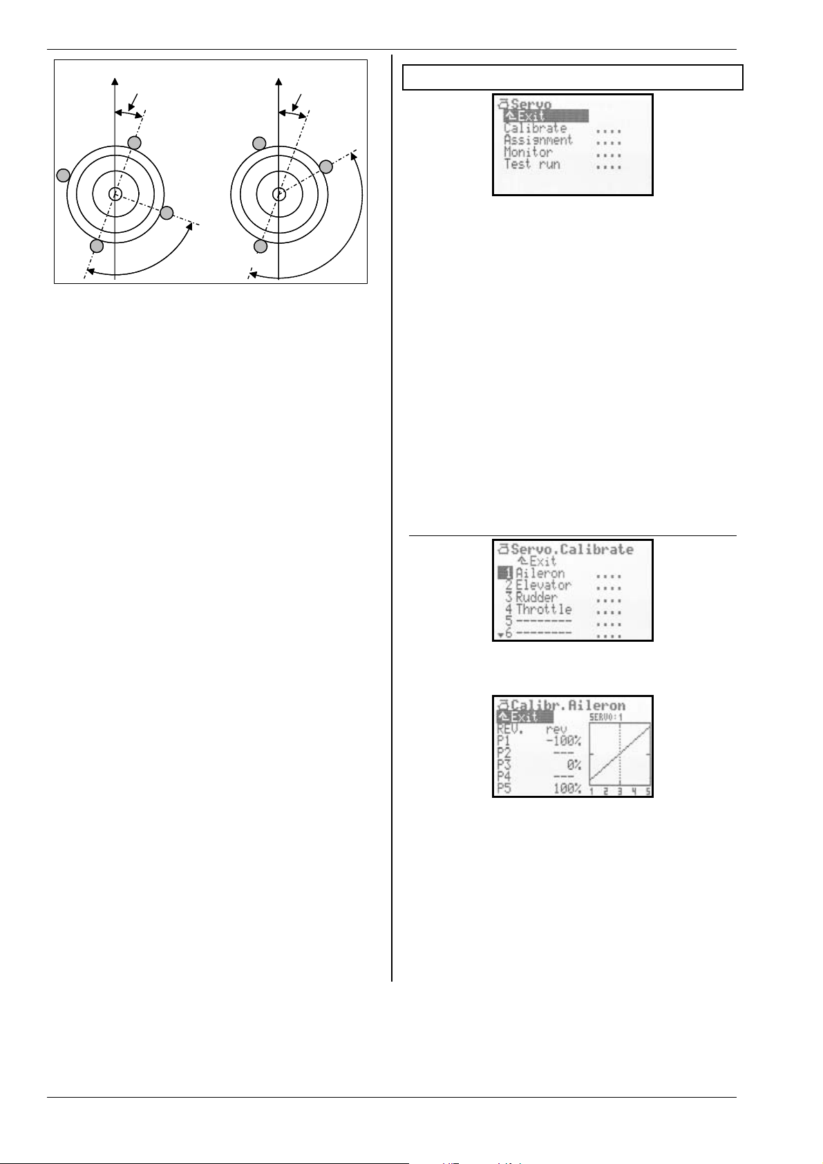
ROYAL evo 7
°
Flight direction
Rotation 20°
Geometry
90°
Flight direction
Rotation 20
140°
TIP:
When you have entered the mechanical values relating
to the swashplate as parameters for the
mixer, the next step is to carry out a careful calibration
of the rotor head servos in Menu K
( Î 16.1.2.). This is the only method of ensuring
brate
accurate swashplate control. The direction of rotation of
the servos can be checked by applying collective pitch
commands. If any servo rotates in the wrong direction,
that servo must be reversed (
bration process you may find it helpful to disconnect
the pushrods between swashplate and rotor head, so
that you can set up the maximum travels (P1, P5).
The control travel settings for roll, pitch-axis and collective pitch can now be entered in Menu H
(Î 14.1.6. und 14.1.10.).
REV.). For the servo cali-
Rotor head
Servo / Cali-
Control
16. Main menu Servo K
What can be done in the main menu
Calibrate
Here you can alter the direction of rotation of the servos, set the servo centre, end-points and limits.
Assignment
This menu shows you the sequence of channels and
servo outputs. Some channels can be assigned a different control function. The servo signal format and number of calibration points can be altered for all servos.
Monitor
This menu displays the travels of all servos by means of
bar graphs and - optionally - a numerical display showing % values.
Test run
You can simulate the movement of a transmitter control. The associated servos then run constantly from one
end-point to the other, at variable speed. This function
is very helpful for range-checking.
Servo?
16.1. Sub-menu Calibrate
TIP: Helicopter with Heim mechanics
If you wish to fly a helicopter with HEIM mechanics,
please use this procedure:
1. Select
2. Assign a vacant servo channel to
3. In the
4. The servo
HELIccpm as template for the new model
Pitch-axis
Rotor head mixer set the geometry to 90°.
This ensures that the servos
HEAD le and
HEAD ri are controlled only by the transmitter
controls for roll and collective pitch
Head f/r is not required. This channel
should be left vacant at the receiver.
The sub-menu
their names. When you select a channel / servo, the following display appears (example: SERVO 1 / aileron):
In this menu you can change the following:
- the direction of servo rotation
- the servo centre
- the servo end-points
- and - if necessary - the intermediate servo travel
points:
All changes to the parameters REV. and the servo calibration points
graph, providing a clear, easily understood means of
checking the settings.
P2 and P4
Calibrate lists all channels 1 - 7 with
REV.
P3
P1 and P5
P1 ... P5 are immediately reflected in the
Page 44
Page 46

H
Display structure
Line 1 always displays the name of the selected servo (in
our example the
channel number of the selected servo is shown (example:
SERVO: 1).
The numbers
to the servo calibration points
16.1.1. Parameter:
To reverse the direction of servo rotation simply select
REV. parameter and press the ENTER button or
the
one of the two 3D digi-adjustors. The cursor changes
to the value
(normal servo rotation). To reverse the servo’s direction
of rotation simply press the REV/CLR button:
the curve is “reversed”;
the value changes from
16.1.2. Parameter:
You can carry out several tasks by adjusting the servo
calibration points
In detail these are:
x setting the maximum working range of the servo. The
P1 and P5 set here (servo end-points) are
values
never exceeded (limit values). This serves to protect
the servos from mechanical stalling at either endpoint / maximum travel;
x setting symmetrical control surface travels;
x matching the travels of multiple servos to each other
(e.g. two aileron or two elevator servos), so that the
control surfaces work exactly in parallel;
x compensating for mechanical discrepancies in the
control surface linkage. Using the intermediate points
P2 and P4, for example, it is possible to match the
travel of two control surfaces accurately between
servo centre and servo end-point;
x setting deliberately non-linear servo travel (= curve),
e.g. for the throttle servo in power models, in order to
obtain a linear speed change over the full range of
throttle control (throttle curve).
This is the procedure for calibrating a servo:
1. Servos which are operated directly by transmit-
ter controls e.g.
der, Throttle, L.gear
Check first that the direction of rotation of the servo
matches the movement of the transmitter control.
If necessary, reverse the direction using the
para-meter (Î 16.1.1.).
Important: if you subsequently reverse the direction of servo rotation, it will be necessary to repeat
the calibration process.
Aileron servo). Above the graph the
1 ... 5 below the graph (X-axis) correspond
P1 ... P5.
REV. (servo reverse)
rev (servo rotation reversed) or nor.
rev nor.
P1 … P5
P1 … P5.
Aileron, Elevator, Rud-
, ...
REV.
ROYAL evo 7 - Instructions
2. Servos which are controlled by mixers
e.g.
AILERON+, DELTA+, V-TAIL+, ...
With these servos the direction of servo rotation is
initially irrelevant, as the correct direction for the
control surface movement will be set later during
the mixer set-up process.
Exception: the following servos in model helicop-
ters:
HEADle, HEADri, HEADf/r, TAIL, ...
3. Select one of the calibration points
activate the % value using the ENTER button, or by
pressing one of the 3D digi-adjustors. Now press
the digi-adjustor assign button < F >.
Regardless of the position of the associated trans-
mitter control, or any control and mixer settings,
the servo now automatically adopts the position
corresponding to the percentage figure at the selected calibration point. With one hand you can
now measure and check the control surface travel
easily and conveniently (ruler, venire calliper), while
the other hand remains free, so that you can alter
the value using the UP / DOWN buttons ( / ) or
one of the two 3D digi-adjustors.
Multiple servos (e.g. all
HEAD servos, ...) automatically adopt the same posi-
tion; these should run in the same direction as the
selected servo after you press the digi-adjustor assign button < F >. If this is not the case, the direc-
tion of servo rotation must first be reversed using
REV. ( Î 16.1.1.).
When the travel is correct, press the digi-adjustor
assign button < F > once more. The servo now
takes up the position corresponding to the associated transmitter control.
Press the ENTER button or one of the 3D digi-
adjustors to conclude the set-up process for the selected point.
The number of variable servo calibration points (min.
two, max. five points) varies according to the setting
you selected when you assigned the servo (Î 16.2.).
Aileron, all DELTA+, all
P1 … P5 and
! Note:
The servo calibration facility should only be used for
fine-tuning the system. We strongly recommend that
you start by carefully adjusting the mechanical system.
You should never reduce the servo end-points
P5 by more than about 10 … 20%, otherwise you forfeit
a proportion of the servo’s full power, servo accuracy is
reduced, and the effect of servo gearbox play is exaggerated. It is equally important that you should not
change the servo centre setting by more than about 10
… 20%, otherwise the servo will exhibit non-linear running characteristics in both directions.
P1 and
TIP: Vertical reference line
The dotted vertical line in the graph is simply a guide,
indicating the current position of the associated transmitter control. If you have activated a value using the
digi-adjustor assign button < F >, the vertical line
jumps to the corresponding point and remains there
until you press the assign button again, or move the associated transmitter control.
ENGLIS
Page 45
Page 47
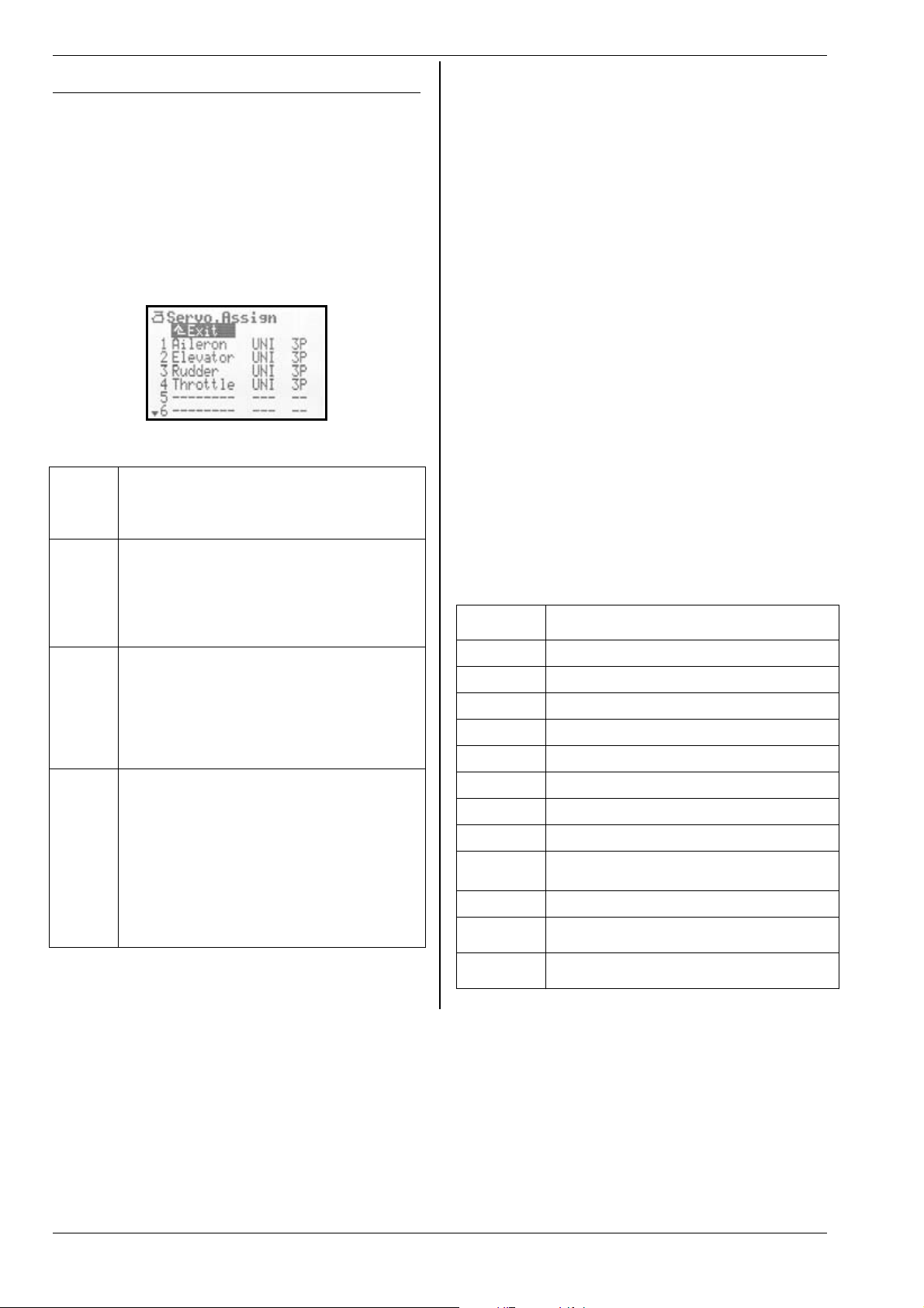
ROYAL evo 7
16.2. Sub-menu: Assignment
This menu shows you the channel and servo output sequence for all channels 1 - 7. The servos must be connected to the receiver in the model in the sequence
shown in this menu. The servo sequence varies according to the selected model template and the selected
servo configuration (MULTIPLEX, HiTEC, Futaba, JR)
(Î 18.6.3.). You can assign a different or particular control function to certain channels (= partially free servo
assignment).
You can also switch each servo from UNI to MPX servo
signal format. At the same time you can select the
number of calibration points for each servo at this point.
Table for
Col. 1
Col. 2
Col. 3
Col. 4
Servo.Assign menu
Channel / servo number
ROYALevo 7 max. 7 channels / servos
The transmission mode (PPM 6 or 7) is set
automatically (Î 16.2.)
Channel / servo name
Here the name of the transmitter or mixer
which is assigned to the channel is displayed.
“- - -“ means that this receiver output is not in
use. In this case a neutral signal is generated
at the output.
Servo signal format
If not all of the servos / speed controllers /
gyro connected to the receiver have the
standard UNI servo signal format (neutral
pulse width = 1.5 ms), you can change the
signal format to MPX (1.6 ms neutral pulse
width) for each receiver output individually.
Servo calibration points
At this point you can define how many calibration points will be available in the Servo
Calibrate menu (Î 16.2.).
2P 2 points (e.g. for throttle, aero-tow)
3P 3 points (e.g. elevator, rudder)
5P 5 points
(if non-linear characteristics are to be
corrected, or deliberately generated)
This is the procedure for:
x carrying out the assignment process
x changing the servo signal format
x selecting the number of calibration points:
1. Select the channel / servo number, then
press the ENTER button or the 3D digi-adjustor
2. Select the function (control or mixer)
(or press REV/CLR to erase the assignment),
then press the 3D digi-adjustor
Note:
If the assignment of the selected channel is fixed,
this field is skipped; continue with 3.
3. Select the signal format (or not, as required),
then press the ENTER button or the 3D digiadjustor.
4. Select the number of calibration points,
then press the ENTER button or the 3D digiadjustor
The cursor now jumps back to the servo number, to indicate that the settings for the selected channel are
completed.
16.2.1. Free assignment with fixed-wing models
With fixed-wing models based on the model templates
BASIC1, BASIC2, ACRO, DELTA, GLIDER, 4FLAP, various
transmitter controls can be selected for the free / variable channels. You can find out which channels are free
or variable by consulting the descriptions of the fixedwing model templates (Î 20. onward):
Available
control
Elevator
Rudder
Throttle
Spoiler
Flap
L. gear
Aero-tow
Brake
Gyro
Mixture
AUX1
AUX2
M.naut1
M.naut2
Note
Elevator signal only no mixing
Rudder signal only no mixing
Throttle signal only no mixing
Spoiler signal only no mixing
Flap signal only no mixing
Retract signal only no mixing
Aero-tow signal only no mixing
Brake signal only no mixing
Gyro signal with all mixed signals from the
Gyro mixer
Mixture signal only no mixing
AUX1/2 signal only no mixing
Control signal for MULTInaut IV receiver
module Î 24.
Page 46
Page 48

H
16.2.2. Free assignment with model helicopters
If you have set up a model helicopter based on one of
the model templates HELImech or HELIccpm, various
transmitter controls can be selected for the free or variable channels. You can find out which channels are free
or variable by consulting the descriptions of the helicopter model templates (Î 20. onward):
Available
controls
Note
ROYAL evo 7 - Instructions
Press the ENTER button or one of the 3D digi-adjustors
to close the Servo Monitor.
16.4. Sub-menu: Test run
Automatic servo run, designed for test and demonstration purposes or as an “electronic aid” for rangechecking.
Pitch-ax
Yaw
Throttle
Spoiler
RPM
L. gear
Aero-tow
Brake
Gyro
Mixture
AUX1
AUX2
Coll. P.
16.2.3. Special features when assigning
The transmission mode PPM 6 or PPM 7 is set automatically:
Last servo on channel 6 PPM 6
Last servo on channel 7 PPM 7
Problems may occur with PPM 6 and certain older types
of speed controller, in which case it may help to assign
any function to channel 7. This forces PPM 7 operation;
you do not need to connect a servo to the output.
Pitch-axis signal only no mixing
Yaw signal only no mixing
Throttle signal, plus mixed throttle curve,
throttle limiter, direct throttle, EMERGENCY
throttle CUT
Spoiler signal only no mixing
Control signal for speed controller
Retract signal no mixing
Aero-tow signal mixing
Brake signal mixing
Gyro signal, including all mixed signals
from the
Mixture signal only no mixing
AUX1/2 signal only no mixing
Coll. pitch signal only no mixing
Gyro mixer
16.3. Sub-menu: Monitor
The Servo Monitor is a substitute for a receiving system
and servos, enabling you to check the function and operation of servos, speed controllers and - especially gyro systems (for which an external effect is not easy to
detect), and seek and eliminate faults.
Call up the menu, then press the ENTER button or a 3D
digi-adjustor; the Servo Monitor then appears.
Two display variants are available:
x graphic, with bar-form display of output signals
(Fig. 1), and
x numerical, with display of % values (Fig. 2).
You can switch between the two displays using the UP /
DOWN buttons ( / ) or one of the two 3D digi-
adjustors.
As soon as you select a transmitter control, the transmitter generates a constant control signal with variable
transit time, i.e. from one end-point of the control to the
other. All servos which are operated by this transmitter
control, either directly or via a mixer, start running.
You can interrupt the test run by either of two methods:
x Press the REV/CLR button “ Control
x Select no transmitter control (“ - - - - - - - “)
The transit time can be set to any value in the range 0.1
– 4.0 seconds.
“ appears
17.Main Menu Timer A
The ROYALevo7 features a stopwatch with alarm function which can be used for various timing tasks. The
stopwatch counts up to 4½ hours with a resolution of
one second.
Line 1:
This is the time which has elapsed since the timer
started. If you select this field, you can erase the time
using the REV/CLR button.
The stopwatch can also be reset by pressing the
REV/CLR button when you are in one of the status displays 1 - 3.
Line 2:
This is where you set the alarm time. For example, if the
motor run of an electric-powered model is four minutes,
you should set
together the motor run time based on the throttle setting, and emits a warning sound once the set alarm time
has elapsed.
The method of entering the alarm time differs from the
usual procedure: here the value is entered digit by digit:
press the ENTER button or one of the 3D digi-adjustors.
The cursor jumps to the hours, which can then be set
using the UP / DOWN buttons or one of the 3D digiadjustors. Every time you press ENTER again, the cursor
moves one place to the right etc.
Time
Alarm
0:04:00 at this point. The timer adds
ENGLIS
Page 47
Page 49

ROYAL evo 7
The timer can be used in two different modes:
1. Set the alarm to 0:00:00
The timer starts at zero, runs upward, counts the
time cumulatively, and is stopped and re-started by
the switch assigned to it. There is no alarm when
the timer is used in this way.
2. Set the alarm to a time other than 0:00:00
The timer starts at the set alarm time, runs downward and triggers an alarm when the selected time
has elapsed.
Alarm pattern:
x at the end of each full minute:
short double beep (ÈÈ)
x from 5 seconds before the set alarm time:
short double beep at one-second intervals (ÈÈ)
x when the alarm time is reached
long double beep (È --- È ---)
Line 3:
Here the screen displays the time which is also shown in
status display 2. It is the difference between the time
and the alarm. The arrow preceding the difference indicates the direction of running of the timer:
The difference runs downward until the alarm time is
reached, and upward if the alarm time is reached or exceeded. The preceding arrow indicates upward or
downward.
Line 4:
At this point you can select the transmitter control
which you wish to use to start and stop the timer. You
can select any control apart from the aileron, rudder
and elevator sticks.
Press the ENTER button or a 3D digi-adjustor to open
the input field. The following display then appears:
Difference (display only)
' running upward
# running downward
Switch
Special case: “H / THR-CUT” and “M / TEACHER“ buttons:
There are two modes of operation involving the “H” and
“M” buttons. The mode is activated according to the
method which you use to leave the “Switch” field when
assigning the timer switch:
1. Toggle “
Press button = timer runs
Press button again = timer stops
2. Latch “
Button pressed = timer runs
Button not pressed = timer stops
The switch you have selected to control the timer (in
our example: F) and the position of the ON state (in our
example:
switch is at the “Timer ON position”, an asterisk
pears after the arrow. The control for the switch is also
shown in status display 2 after the timer time:
…“:
„“:
' = forward) are displayed in line 4. If the
'* ap-
The transmitter control which you now select to operate
the timer will operate the timer in all models which use
the same assignment (Î 18.6.).
If you now press the ENTER button to confirm your action, you can assign the desired transmitter control as
the “Timer Switch” simply by operating it. We call this
process QUICK SELECT.
Leave the transmitter control at the end-point at which
the timer is to run. Close the input field by pressing the
ENTER button or one of the 3D digi-adjustors.
Page 48
Page 50
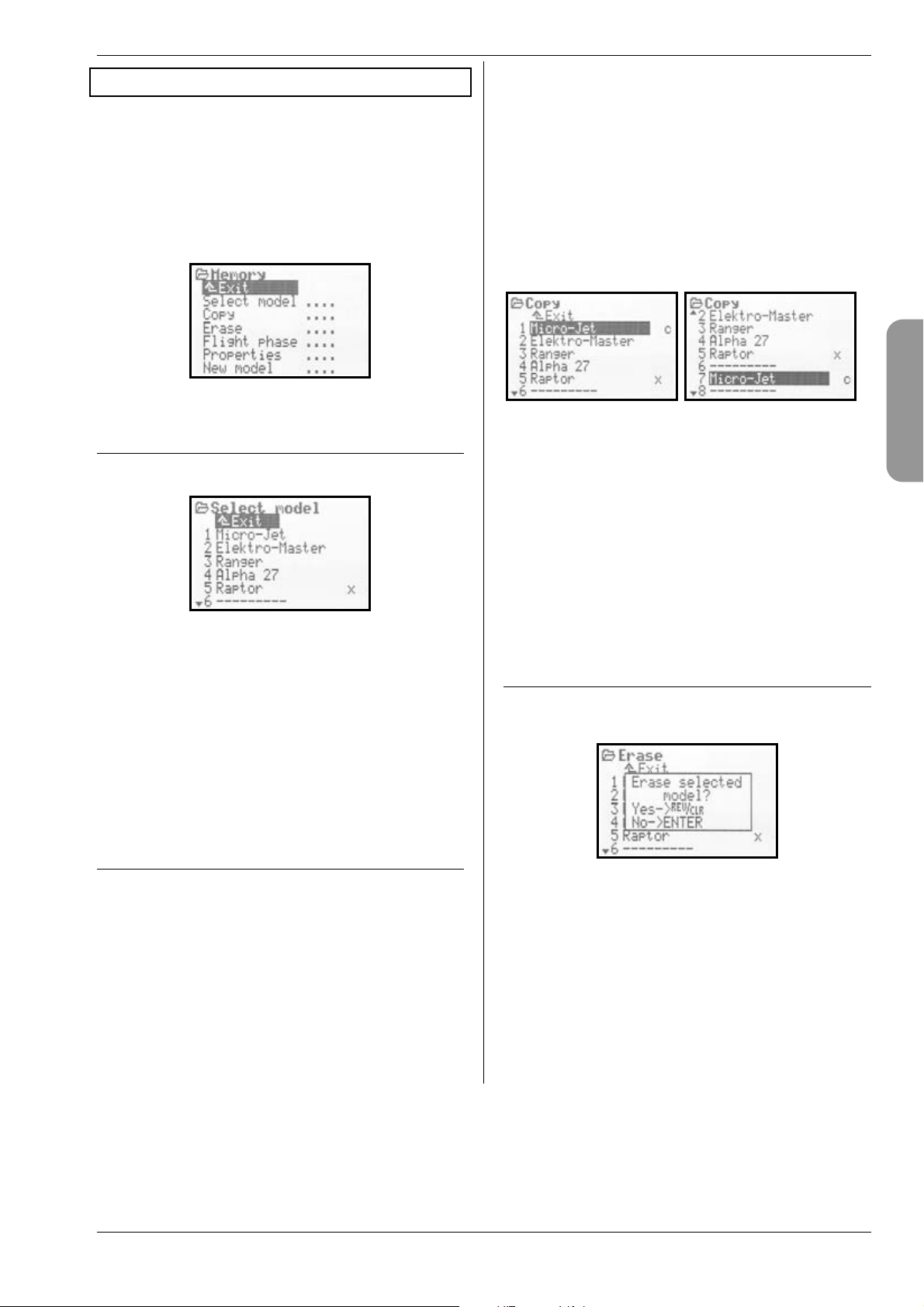
H
18. Main Menu Memory I
The ROYALevo7 has 15 model memories, numbered se-
quentially. You can assign a name up to 16 characters
long to each model memory.
The model data is stored in non-volatile memory, and
therefore cannot be lost even if you disconnect the
transmitter battery from the transmitter.
In addition to memory management (switching, copying, erasing), you can also set up new models (Î 18.6.)
and manage flight phases (Î18.4.) in this menu.
18.1. Sub-menu: Select model
(switch memories)
When you move to the Select model menu, you will
see a list of all 15 model memories:
The active model memory is marked
Empty model memories have no model name:
--------“.
“
It is possible to select an empty memory, but not activate it.
To switch models, select the appropriate memory using
the UP / DOWN buttons ( / ) or one of the two 3D
digi-adjustors, then press the ENTER button or one of
the 3D digi-adjustors. The screen then switches to the
last used status display. The transmitter is immediately
ready for use, and the model can be flown.
x.
ROYAL evo 7 - Instructions
2. Confirm your selection
Press the ENTER button or one of the 3D digiadjustors.
The letter “c” (= copy) now appears after the
model name (Fig. 1).
3. Define the destination
Select a target memory for the copy using the UP /
DOWN buttons ( / ) or one of the two 3D digiadjustors. The model name of the model to be copied and the “c” go with you on the search (Fig. 2).
4. Confirm the destination
Press the ENTER button or one of the 3D digiadjustors.
Fig. 1 Fig. 2
x If the destination memory is empty, the copy is cre-
ated immediately.
x If the destination memory is already occupied, the
security query appears: “Overwrite existing model?”.
x At this point you can interrupt the copy process by
pressing the ENTER button or one of the 3D digiadjustors.
x If you wish to overwrite the existing model, press
the REV/CLR button.
After the copy process the previously active model is
called up again.
18.3. Sub-menu: Erase
If you wish to erase a model memory, first select the
memory, then press the ENTER button or one of the 3D
digi-adjustors. A security query now appears:
ENGLIS
18.2. Sub-menu: Copy
Making a copy of one model memory can be a useful
time-saver if, for example, you wish to set up a new
model which is similar to one you already own, or if you
want to make experimental changes to the settings of a
model without losing the existing settings. The copy
process copies all the settings for the transmitter controls, mixers, servos, timers, model name and trims.
There are four steps to copying a model memory:
1. Select the model
Select the model which is to be copied using the UP
/ DOWN buttons ( / ), or one of the two 3D digi-
adjustors.
x If you wish to erase it,
press the REV/CLR button to confirm your action;
x If you do not wish to erase it,
press the ENTER button or a 3D digi-adjustor.
Erasing is not possible if you have selected the memory marked
Page 49
x, as this memory is currently active.
Page 51

ROYAL evo 7
18.4. Sub-menu: Flight phases
Flight phases are groups of settings (data) which can be
called up for a particular model by operating a switch.
The settings can be optimised for different flight tasks.
For each flight phase you can adjust the transmitter
control settings individually to suit the requirements of
the model (e.g. reduced travels for SPEED, extended
flaps for LANDING, different collective pitch and throttle
curves for model helicopters, …). All the settings which
can be modified for the various flight phases are assigned the code numbers 1 … 3 or 4 associated with the
flight phase (Î 14.). The ROYALevo7 also features flight
phase specific digital trims (Î 12.), i.e. the trims can be
set separately for each flight phase, and the settings are
stored permanently. This simply means that the model
is always perfectly trimmed in each flight phase.
For fixed-wing model aircraft we have provided three
flight phases. Flight phases 1 … 3 are selected using
switch J: “F-PH 1-3”.
For model helicopters an additional fourth flight phase
is provided for auto-rotation. This is selected using
switch I “A-ROT”, and always has highest priority. This
means: the auto-rotation flight phase
ways activated when switch I “A-ROT” is operated, regardless of the flight phase 1 …3 currently selected using switch J “F-PH 1-3”.
The transition between flight phases is “soft” (it takes
about one second), in order to avoid sudden servo
movements when the change-over is made. The exception to this rule is the auto-rotation flight phase with
model helicopters. If you operate switch I “A-ROT”, the
transition to the
ately.
The Flight phase menu for a fixed-wing model may look
like Fig. 1; for a helicopter like Fig. 2:
Fig. 1 Fig. 2
Fig. 1 contains the following information:
x The first column shows the number of the flight
phase, followed by the name of the flight phase
x Flight phases 1 and 3 are blocked
(names crossed out)
x Flight phase 2
x after the name)
(
x The flight phase switch is
The same applies to the four helicopter flight phases
shown in Fig. 2.
18.4.1. Selecting names for flight phases
The following flight phase names are available:
NORMAL, START1, START2, THERMAL1, THERMAL2,
SPEED1, SPEED2, CRUISE, LANDING, HOVER, 3D, ACRO
The name serves only as information to the user. The
number of the flight phase is crucial to its properties, i.e.
flight phases of the same name do not necessarily share
the same settings or characteristics.
AUTOROT flight phase occurs immedi-
NORMAL is currently active
J> on the right-hand side.
AUTOROT is al-
This is the procedure for changing a flight phase
name:
Use the UP / DOWN buttons ( / ) or one of the two
3D digi-adjustors to select a flight phase, and confirm
your action by pressing the ENTER button or one of the
3D digi-adjustors the cursor jumps to the name input
field.
You can now select a suitable name using the UP /
DOWN buttons ( / ) or one of the two 3D digiadjustors.
Press the ENTER button or a 3D digi-adjustor to conclude the procedure. Note: this requires a double press
if you have changed the name of the currently active
flight phase.
Exception
The name for flight phase 4 for helicopters is
and this cannot be changed.
18.4.2. Blocking / releasing flight phases
You can release or block any flight phase using the
REV/CLR button. By blocking a flight phase you can
eliminate the danger of launching a model after accidentally selecting a flight phase which does not contain
the correct settings.
If you select a blocked flight phase using one of the
flight phase switches J (“F-PH 1-3”) or I (“A-ROT”), you
will hear a continuous warning sound. The last used
flight phase remains active, and its number is shown in
status display 2. The name of the blocked flight phase
which you have selected is shown crossed out.
This is the procedure for blocking / releasing flight
phases:
Select a flight phase, then press the ENTER button or
one of the 3D digi-adjustors to confirm your action
the cursor jumps to the flight phase name. You can now
switch between “free” and “blocked
button.
Selecting another name using the 3D digi-adjustor also
releases a blocked flight phase.
Note:
The currently active flight phase (marked with
be blocked.
18.4.3. Copying flight phases
We recommend the following procedure if you wish to
make a start using different flight phases:
Begin with just one flight phase, leaving the other flight
phases blocked. Your model should now be test-flown
and all settings carefully optimised. The flight phase can
now be copied. When you switch to the new flight
phase(s) you can be confident that the model will behave in the usual manner. All you have to do now is
make the desired modifications to the copies.
” using the REV/CLR
AUTOROT,
x) cannot
Page 50
Page 52

ROYAL evo 7 - Instructions
H
The active flight phase is marked x. Only the active
flight phase can be copied. The following steps are necessary:
1. Select the active phase (
buttons ( / ), or use one of the two 3D digiadjustors.
2. Press the 3D digi-adjustor (or ENTER) twice;
the cursor jumps to the “
3. Select the destination phase for the copy using the
UP / DOWN buttons ( / ) or one of the two 3D
digi-adjustors;
the “
5. Press the ENTER button or one of the 3D digiadjustors to conclude the copy process.
x “ changes to a “ c “ = copy.
x ) using the UP / DOWN
x “.
18.5. Sub-menu: Properties
The Properties sub-menu is a dynamic menu. The display may look as shown below, depending on the
model type (fixed-wing or helicopter) of the active
memory:
18.5.3. Parameter:
L
This parameter shows the assignment (which transmitter control operates which function) with which the current model was set up. The field only provides information to the user, and cannot be changed.
18.5.4. Parameter:
I
Adjust. range ON, OFF
Here you can determine whether your current model
helicopter requires a throttle curve to control the throttle function, or whether fixed values are to be used (e.g.
electric helicopters with brushless motor in “regulator”
mode) (Î 14.1.11.).
18.5.5. Parameter:
, US/ES
I
Assignment
Fixed-wing models and helicopters
Information field; cannot be changed
Throttle curve
Model helicopters only
The parameter affects the active
model only
Shift
US/ES language set only, with
For
fixed-wing models and helicopters
Parameter affects the active model
only
ENGLIS
18.5.1. Parameter:
L
This parameter indicates which model template was
used to set up the current model (Î 18.6.2.). The field is
only for the user’s information, and cannot be changed.
18.5.2. Parameter:
I
Adjust. range Mode 1 ... Mode 4
The mode (stick mode) parameter is used to define
which stick controls which function in the model. The
mode can be changed at any time either here or in the
Setup / Control menu (Î 13.3.1.).
Template
Fixed-wing models and helicopters
Information field; cannot be changed
Mode
Fixed-wing models and helicopters
Parameter affects the active model
only
The menu point “Shift Switch” only appears if you are
using the
receiver are used it is sometimes necessary to adjust
Shift to suit the receiver:
US/ES language set. When other makes of
+ = Positive shift
- = Negative shift
! Note:
If you intend using the system with components made
by a variety of manufacturers, please note that careful
testing is essential. It is not possible for MULTIPLEX
Modellsport GmbH to guarantee that its systems will
function perfectly with products made by other companies.
18.5.6. Parameter:
I
This is where you can enter a name for your model; the
name can be up to 16 characters long. When you set up
a new model, it is initially assigned the name of the
model template you have used. The text for the name is
entered using the keypad; the procedure is described in
Section 11.1.3.
Name
Fixed-wing models and helicopters
Parameter affects the active model
only
Page 51
Page 53

ROYAL evo 7
18.6. Sub-menu: New Model
New models are set up using the New Model submenu.
When you open the sub-menu, the following display
appears:
You must work through all the menu points
Servo Config. and Mode to set up a new model, and
then confirm your action with
18.6.1. Parameter:
L
The Memory number for the model you are about to
set up is dictated by the transmitter; it is always the first
free memory. The
you wish to store the new model in a different memory,
you can subsequently copy the new model to another
memory (Î 18.2.).
Note:
If there is no vacant memory, the screen displays the
number
memory!
the menu. You cannot set up another model unless you
first erase a model which you no longer need (Î 18.3.).
18.6.2. Parameter:
In this menu point you inform the transmitter what type
of model you wish to set up. First you have to differentiate between a helicopter and fixed-wing model. There
are several model templates in each basic type:
BASIC 1
BASIC 2
ACRO
DELTA
GLIDER
4 FLAPS
-1 and the warning: Attention! No free
. If this should happen, press EXIT to leave
Model templates for fixed-wing models
Memory No.
Information field; cannot be changed
Memory No. cannot be changed. If
Template
For simple model aircraft with up to
one aileron servo, also other models
For model aircraft with two aileron
servos
For powered aerobatic models and
hot-line electric models
For deltas and flying wings
For gliders and electric gliders with
two aileron servos
For gliders and electric gliders with
four-flap wings
OK.
Template,
Model templates for helicopters
HELImech
HELIccpm
The advantage of using model templates for setting up
a new model is that many of the basic settings are
automatically defined correctly, leaving you just to carry
out final adjustments. The template determines which
mixers can be used for the selected model type, and
which control assignment is used (“which transmitter
control operates which function?”), which channels the
servos are connected to, and so on. A full description of
the model templates will be found in Section 20.
18.6.3. Parameter:
The servos must be connected to the receiver in a particular sequence defined by the model template you
have selected. Every radio control system manufacturer
has its own standard in terms of servo sequence at the
receiver output sockets. The
the ROYALevo7 allows you to select the sequence of ser-
vos at the receiver:
MPX
HITEC
FUTABA
JR
For a full description of the servo sequence please refer
to the description of the model templates (Î 20.).
18.6.4. Parameter:
The Mode parameter is used to determine which stick
controls which of the primary functions (Î 13.3.1.). This
setting can be changed at any time.
18.6.5. Parameter:
Once you have set up all the parameters described
above, you must press the ENTER button or one of the
3D digi-adjustors on the
up of the new model. The transmitter automatically
switches to the new model you have just set up, and
you can immediately start adjusting the settings.
For model helicopters with mechanical swashplate mixers
For model helicopters with electronic
swashplate mixers (CCPM)
Servo Config.
Servo Config. menu of
MULTIPLEX standard
HiTEC standard
FUTABA standard
JR standard
Mode
OK
OK field to conclude the setting
Page 52
Page 54

H
19. Setting up a new model
19.1. Introduction
When you set up a new model the ROYALevo7 helps
you by presenting a set of model templates. Eight different templates are available:
Templates for
standard and
fixed-wing models
1. BASIC1 7. HELImech
2. BASIC2 8. HELIccpm
3. ACRO
4. DELTA
5. GLIDER
6. 4 FLAPS
Setting up a new model based on a model template is
very simple, as all parameters and menus not required
for the selected model type are suppressed. This ensures that the menu system is always as clear and simple as possible, and goes a long way to avoiding programming errors.
A detailed description of model templates and their applications, together with full information and set-up facilities, are found on the section starting with Î 20.
“Step by step to your destination”
There are various ways of proceeding when you are setting up a new model. The following procedures for
fixed-wing models (Î 19.2.) and helicopters (Î 19.3.)
describe the method which in our opinion takes you to
the finishing post most quickly.
Templates for
model
helicopters
19.2. A new (fixed-wing) model
Step n Setting up a new memory
A new model is initially set up in Menu I Memory, in the
New Model sub-menu (Î 18.6.).
In this menu the following happens:
1. The first empty memory is automatically selected
for the new model.
(
Memory No. parameter Î 18.6.1.)
2. Select a model template to suit the new model.
(
Template parameter Î 18.6.2.)
From the eight templates available pick the one
which comes closest to your model.
(Description of model templates Î 20.)
3. Select the manufacturer-specific servo sequence at
the receiver (from MULTIPLEX HiTEC, Futaba or JR)
(
Servo config parameter Î 18.6.3.)
4. Select your preferred stick mode, i.e. which stick is
to control which model function (e.g. throttle right
or left, aileron right or left, …)
(
Mode parameter Î 18.6.4.)
5. Leave the menu by selecting
this completes setting up the new model.
6. In the Control sub-menu of the Setup menu, select
the control neutral settings for:
Thr. min Idle
Spoiler min retracted
(no braking effect)
(Î 13.3.3. und 13.3.4.)
OK
ROYAL evo 7 - Instructions
Step
o Entering a model name
Enter the model’s name in the menu:
Memory / Properties.
I
Name parameter Î 18.5.6.)
(
p Connecting the servos
Step
Connect the model’s servos, speed controller etc. to the
receiver, taking care to use the socket sequence described in the model template which you selected when
you initially set up the new model (
parameter). The channel sequence can also be seen in
Menu K
Servo / Assignment.
Servo config.
TIP:
Not all receiver channel assignments are fixed; some
channels can be altered, i.e. they are unused and can be
assigned freely. For example, you can assign a throttle
or aero-tow channel if necessary for a glider or electricpowered glider. You can assign additional functions to
the servo channels which are not in use by basic functions (e.g. retracts, second elevator servo, aero-tow, vacant AUX channels, …). Changes to the servo assign-
ment can be made in Menu K
ment
( Î 16.2.).
Note:
If you wish to connect devices (servos, speed controller,
…) which vary in signal format, it is possible to set up
each channel separately (options: UNI / MPX) in Menu K
Servo / Assignment
q Switching on the transmitter and receiver
Step
( Î 16.2.).
! Always keep to the standard sequence!
Always switch the transmitter on first,
and only then the receiver.
! Caution!
Injury hazard from motors bursting into life.
Check carefully that there is no danger of a motor
starting up accidentally when you switch on.
The model will now respond to control commands from
the transmitter. However, all the settings (servo direction, neutral setting, control surface travels) still have to
be checked and adjusted.
Step
r Calibrating the servos
The term “calibration” in this connection means adjusting the following features of the servos:
- Direction of rotation
- Centre setting
- End-points
The servos are calibrated in Menu K
brate
( Î 16.1.)
Note:
Please take great care when calibrating the servos. They
can only work accurately enough to provide precise
control of your model if this process is carried out properly and carefully. “Measuring is always better than
guessing!”
Page 53
Servo / Assign-
Servo, Cali-
ENGLIS
Page 55

ROYAL evo 7
Step s Setting up mixers
Mixers are set up in Menu G Mixer. This menu is dynamic, i.e. only those mixers used in the model are displayed. Mixer types and their function are described in
detail in the section on model templates (Î20.).
By default the mixers are assigned sensible average settings for the model template in use, but they still have
to be fine-tuned to suit your particular model.
Details on the subject “setting up mixers” can be found
in the Mixer section (Î 15.4.).
Step
t Setting up the transmitter controls
Transmitter controls are set up in Menu H Control.
This menu is dynamic, i.e. only the controls required for
your model / model template are displayed. By default
the control settings are assigned sensible values for the
model template you have selected, but they still need to
be fine-tuned to suit your particular model.
All you need to know on the subject “Setting up transmitter controls” can be found in the Section Î 14.
Step
u Pre-flight checks
Your newly set-up model should now be ready to fly.
But be sure to check all the working systems carefully
before you attempt to fly it.
Fine-tuning, especially of mixers and transmitter control
settings, can only be carried out during the test-flying
procedure with the new model. Please don’t try to make
changes in a menu while the model is flying. It is far
safer and more convenient to use the 3D digi-adjustors
to alter the values (Î 10.2.2.).
Step
v Activating flight phases
If you have set up a model based on one of the model
templates
model’s settings for various flight tasks by switching to
other flight phases. Before activating additional flight
phases the model should first be test-flown and
trimmed out properly in one flight phase (generally the
NORMAL phase), and all mixer and transmitter control
settings finalised. Only then should you activate additional flight phases as required, in order to optimise the
model for different flight situations, such as landing /
aerobatics, thermal / speed, cruise / auto-rotation. Another flight phase has first to be released, and then the
settings can be copied from the first flight phase to the
new one. The transmitter control settings (Menu H
Control
flight phase. All transmitter control settings which are
marked with a small number (
justed separately for each flight phase.
You will find all you need to know about flight phases in
the Section Î 18.4.
BASIC2 ... 4 FLAPS, you can optimise the
Î 14.) can now be optimised for the new
1 …3 or 4) can be ad-
19.3. A new model helicopter
! Safety note
Radio-controlled model helicopters are technically sophisticated and demanding flying machines which require careful setting-up, maintenance and care. If operated incompetently or carelessly they represent a serious potential hazard.
If you are a beginner, this is our advice:
x Start by asking an experienced model pilot for help;
join a club, or enrol at a model flying training centre;
x Ask your local model shop for advice;
x Read all you can on the subject (books, magazines).
Step
n Setting up a new memory
A new model is initially set up in Menu I Memory, in the
New Model sub-menu (Î 18.6.).
In this menu the following happens:
1. The first empty memory is automatically selected
for the new model.
(
Memory No. parameter Î 18.6.1.)
2. Select one of the two helicopter model templates
(
Template parameter Î 18.6.2.)
HELImech
HELIccpm
A detailed description of the helicopter model
templates can be found at Î 20.
3. Select the manufacturer-specific servo sequence at
the receiver (from MULTIPLEX, HiTEC, Futaba or JR)
Servo config. parameter Î 18.6.3.)
(
4. Select your preferred stick mode, i.e. which stick is
to control which model function (e.g. collective
pitch right or left, roll right or left, …)
(
Mode parameter Î 18.6.4.)
5. Leave the menu by selecting
this completes setting up the new model.
6. In the Control sub-menu of the Setup menu, select
the control neutral settings for:
Coll. min Control setting for negative
collective pitch
Thr.limit min Idle setting
(Î 13.3.3. and 13.3.4.)
For models with mechanical rotor
head mixing
For models with electronic rotor head
mixing (CCPM). The type of swash-
plate (e.g. 3-point 120q, 3-point 90q,
...) is irrelevant. The settings for your
particular swashplate type will be entered later.
OK
Step
o Entering a model name
Enter the model’s name in the menu:
Memory / Properties.
I
Name parameter Î 18.5.6.)
(
Page 54
Page 56

ROYAL evo 7 - Instructions
H
Step p Connecting the servos
Connect the model’s servos, speed controller etc. to the
receiver, taking care to use the socket sequence described in the model template which you selected when
you initially set up the new model (
parameter). The channel sequence can also be seen in
Menu K
Servo / Assignment.
Servo config.
TIP:
Not all receiver channel assignments are fixed; some
channels can be altered, i.e. they are unused and can be
assigned freely if auxiliary channels are required. (e.g.
retracts, speed controller = RPM, vacant channels (AUX),
...). Changes to the servo assignment can be made in
Menu K
Note:
If you wish to connect devices (servos, speed controller,
…) which vary in signal format, it is possible to set up
each channel separately (options: UNI / MPX) in Menu K
Servo / Assignment
Step
Servo / Assignment ( Î 16.2.).
( Î 16.2.).
q Switching on the transmitter and receiver
! Always keep to the standard sequence!
Always switch the transmitter on first,
and only then the receiver.
! Caution!
Injury hazard from motors bursting into life!
Check carefully that there is no danger of a motor
starting up accidentally when you switch on.
The model will now respond to control commands from
the transmitter. However, all the settings (servo direction, neutral setting, control surface travels) still have to
be checked and adjusted.
Step
r Calibrating the servos
The term “calibration” in this connection means adjusting the following features of the servos:
- Direction of rotation
- Centre setting
- End-points
The servos are calibrated in Menu K
( Î 16.1.)
brate
Note:
Please take great care when calibrating the servos, as
they can only work accurately enough to provide precise control of your model if this process is carried out
properly and carefully.
Servo, Cali-
TIP:
For the servos
a 2-point servo calibration is sufficient. Do check
TAIL
that the servos rotate in the correct direction before carrying out the calibration process. If you have to reverse
the servo direction subsequently, you will have to repeat the calibration procedure!
Throttle, Collective Pitch,
For calibrating the two reference points
move the assign button, which moves the servo to the
appropriate position regardless of the transmitter control position, and hold it there (Î 16.1.). Change the %
values so that the servos reach the required maximum
travels, without being mechanically stalled at either
end-point (
For the servos
calibration is required. Once again, do check that the
servos rotate in the correct direction before carrying out
the calibration process. If you have to reverse the servo
direction subsequently, you will have to repeat the calibration procedure!
For the servos
accurate calibration can be made by setting up a 5point servo calibration. The number of calibration
points can be selected in Menu K
(Î 16.1.). You must ensure that the servos rotate in the
correct direction before calibrating them. Do this by
moving the collective pitch stick up and down: all the
servos must move the swashplate in the same direction.
To calibrate the individual points
button. All rotor head servos run to the appropriate position, regardless of the transmitter control setting, and
are fixed there. You can now fine-tune the % values so
that the swashplate is exactly horizontal at each calibra-
tion point (
at either end-point (
Step
The swashplate mixer is set up in Menu G Mixer /
Rotor head
HELIccpm assumes a 3-point 120q swashplate with the
“pitch-axis” servo arranged at the rear, and the parameters
to suit this arrangement. If your swashplate is different,
these two settings will have to be altered.
P1 and P5).
Roll and Pitch-axis a 3-point servo
Head f/r, Head le, Head ri a more
Servo, Calibrate
P1 ... P5 use the assign
P2, P3, P4), and is not jammed mechanically
P1 und P5).
s Setting up the rotor head mixer
(only for models with CCPM rotor head!)
(Î 15.8.). The model template
Geometry and Rotation are set up by default
P1 and P5
TIP:
The travel settings for the control functions roll and
pitch-axis are adjusted in Menu H
Travel parameter (Î 14.1.6.)
Step
t Setting up the collective pitch curve
The collective pitch curve is set up in Menu H Con-
trol / Coll. Pitch
For each flight phase a separate collective pitch curve
can be set up, in order to optimise the collective pitch
control system for each flight phase. For example:
x
HOVER
With collective pitch range -2 … +10°, so that the
model is less sensitive at collective pitch minimum.
This provides ultra-fine control for the landing;
x
ACRO
with collective pitch range –10 ... + 10q, so that the
model’s flying characteristics are the same upright
and when inverted;
( Î14.1.10.).
Control under the
ENGLIS
Page 55
Page 57

ROYAL evo 7
x AUTOROT
with collective pitch range –8 ... + 12q, providing the
optimum blade settings for collective pitch minimum
and maximum for auto-rotation landings.
TIP:
In our experience the correct blade pitch angle for hove r i ng i s a ro u n d +5 ° , alt h o ugh t h is d o e s v a r y fr o m mod e l
to model. When setting up the collective pitch curves
you should ensure that this value is reached at approximately the same collective pitch stick position in
all the collective pitch curves, otherwise the model will
“jump” when you switch from one flight phase to another.
! Note: Models with CCPM swashplate
Do not set the collective pitch curve points
to + and - 100%, otherwise symmetrical cyclic movements (pitch-axis and roll) will not be possible at maximum and minimum collective pitch, since the servos
will already be at the limit of their travel (
Depending on the travels for roll and pitch-axis, we recommend setting the max. and min. collective pitch
curve points
P1 and P6 t o a r o u n d 7 0 t o 8 0% .
! Note: Altering the neutral position
If the system is to work correctly it is essential that you
set up the neutral position of the collective pitch transmitter control to suit your preference as a pilot:
Collective pitch minimum forward or back
This setting can be changed in Menu L
trol
(Î 13.3.3.).
Step
u Setting up the throttle curve
The throttle curve (P1 ... P5) is set up in Menu H Con-
trol / Throttle
In model helicopters the throttle servo, or the electric
motor speed controller, is not controlled directly by a
transmitter control, but by the collective pitch stick via a
mixer (collective pitch Æ throttle mixer). The effect of
the collective pitch stick on the throttle servo / electric
motor is determined by the throttle curve. The aim of
the throttle curve is to obtain constant rotational speed
over the full range of collective pitch, i.e. for every collective pitch stick position. Only then is it possible to
achieve stable flying characteristics with a helicopter.
The throttle curves for the model templates
HELIccpm are set up b y d e f a u l t , and it is only po s -
and
sible to fine-tune them when the model is flying.
( Î 14.1.11.).
! Note: Throttle limiter and direct throttle
The throttle limiter (F) must be left at the full-throttle
position, and the direct throttle switch DTC (N) must be
set to “0” (= OFF). Only then is the collective pitch Æ
throttle mixer active, and the throttle servo / electric
motor responds to the collective pitch stick according
to the throttle curve you have set up.
! Note:
Electric helicopters with brushless motor used in
“regulator” (governor) mode
If you are using a speed controller for a brushless electric motor with “regulator” (speed governor) mode, a
throttle curve is not required. Instead a nominal rotational speed has to be defined, as the speed controller
automatically holds the speed at the pre-set nominal
P1 and P6
P1 and P5).
Setup, Con-
HELImech
speed. The
the menu
All the throttle curve points (
same value (fixed value). Any changes to one point affect all the throttle curve points.
Setting the idle speed
The
speed when the throttle limiter is at the Idle position.
The idle speed can be fine-tuned using the idle trim
(trim buttons for the collective pitch stick). An idle
speed is not required for electric helicopters. In this case
set the value for
so that the motor is stopped when the throttle limiter is
at the idle position.
Step
(static tail rotor compensation / REVOMIX)
The tail rotor mixer is set up in Menu G Mixer / TAIL
(Î 15.7.).
In the model templates
rotor compensation is switched off by default. If you are
using a modern gyro system in your helicopter which
only operates in heading-hold mode, all the settings for
the
TAIL mixer must be set to OFF or 0% (but please
read the notes on this in the instructions supplied with
the gyro system!).
Throttle curve can be switched OFF in
Memory / Properties ( Î 18.5.4.).
P1 ... P5) then have the
Min. parameter is used to set the motor’s idle
Min. to 0% and the trim to minimum,
v Setting up the tail rotor mixer
HELImech and HELIccpm tail
TIP:
The alternative is not to connect the tail rotor to the receiver output
using the yaw stick, without a mixer. To achieve this you
must assign
Assignment
then be connected to this channel.
If your gyro system can work in normal or damping
mode, the
correctly, as it reduces the characteristic tendency for
the model to yaw (rotate around the vertical axis) when
there is a torque change, i.e. every time the pilot applies
a collective pitch command. This eases the workload of
the gyro, and ensures optimum tail stabilisation.
This is the procedure for setting up tail rotor compensation:
1. Ensure that the servo output arm and the tail rotor
pitch lever are at right-angles to the tail rotor pushrod when the tail rotor servo is at neutral. If necessary, adjust the length of the tail rotor pushrod to
achieve this. At this setting tail rotor compensation
will be automatically close to correct for hovering.
TAIL, but to control the tail rotor directly
Yaw to a free channel in Menu K Servo /
(Î 16.2.). The tail rotor servo or gyro can
TAIL mixer should be activated and set up
TIP:
When both tail rotor blades are folded to one side,
the distance between the blade tips should be in
the range 10 - 20 mm, depending on the model.
2. Now define the starting point for the tail rotor
compensation mixer: move the collective pitch stick
to the appropriate position (hover point) and trans-
fer the value of the
ter to the
parameter Î 15.7.4.).
Zero point parameter (Zero point
Collective pitch parame-
Page 56
Page 58

H
3. The value for tail rotor compensation for climb can
now be set using the
Coll.+ parameter.
Move the collective pitch stick to the “climb” position (collective pitch maximum) and set an initial
value at which the distance between the tail rotor
blade tips is approximately doubled.
Now move the collective pitch stick to the “descend” position (collective pitch minimum) and set
an initial value at which the distance between the
tail rotor blade tips is about 0 … 5 mm.
For the other flight phases start with the values you
have just set. Fine adjustment of tail rotor compen-
sation (
Coll.+, Coll.-) for the individual flight
phases can only be carried out during flight-testing.
In the Auto-rotation flight phase (
AUTOROT) no tail rotor
compensation is required, as there is no torque to be
allowed for since the motor is either stopped or idling.
Set the value
meters. Set the
OFF for the Coll.+ and Coll.- para-
Offset parameter so that the tips of
the folded tail rotor blades are in line with each other
( blade pitch angle 0°).
Step
w Setting up and testing the gyro
The model templates are designed on the assumption
that a gyro system (normal / damping or heading-hold
type) - nowadays a standard feature - is used, with gyro
gain remotely variable from the transmitter via a separate channel.
In the
HELImech and HELIccpm model templates the
simplest method of gyro gain control is selected for the
ROYALevo 7; this is the gyro mode
Control (Î
15.6.1.). This provides for manual adjustment of gyro
gain (same gain for all flight phases) using the
Gyro
control (slider “E”). Later you can set up flight phase dependent gyro control (
Damping or Heading mode).
The first step here is to determine the position of the
Gyro control at which maximum gyro gain is obtained.
This is done by moving slider “E” to one end-point and
rotating the model around its vertical axis. At maximum
gain you will see the largest corrective tail rotor movement. If maximum gain is at the opposite position of the
slider, the direction of the Gyro channel must be “reversed” (Î 16.1.1.).
The optimum gain settings for the gyro can only be
found through flight testing. For initial test-flights we
recommend a gain of around 50%. Increase the gain
gradually during the first few flights until the tail starts
to oscillate. You should then reduce gain just to the
point where the oscillation ceases. This is the optimum
gyro gain setting.
! Caution!
Before you fly the model it is absolutely essential to
check that the gyro is working correctly, i.e. that it is set
up to correct any unwanted yaw movement. If it is set
up in the opposite direction, the gyro will exaggerate
any yawing tendency, rendering the helicopter uncontrollable. Please read the notes on this subject in the
gyro’s operating instructions.
ROYAL evo 7 - Instructions
Step
W Getting to know the method of working
of the throttle limiter and direct throttle
Throttle limiter
The throttle limiter function limits the maximum speed
of the motor to a variable value in the range idle to fullthrottle, and thereby makes it much safer to start and
adjust the motor. The control for the throttle limiter is
slider F.
If the throttle limiter is at the idle position, the motor
runs at the speed set using the
Min. parameter (Î
14.1.12.) (the collective pitch stick now has no effect on
throttle). In this position you would, for example, start
the glow motor (idle speed can be adjusted using the
collective pitch trim buttons). Only when the model is
standing on the launch pad at a safe distance, and you
have checked that the collective pitch stick is at collective pitch minimum, should the throttle limiter be
gradually moved to the full-throttle position. The motor
now accelerates to the set throttle value for collective
pitch minimum (
P1 on the throttle curve Î 14.1.11.).
The throttle curve is now active, and throttle is controlled by the collective pitch stick.
Helicopter throttle curve
Throttle
+100%
Range blocked by
throttle limiter
+50%
min.
P2
P1
0%
P3
Actual course
of throttle
Programmed
throttle curve
max.
Collective pitch stick
r
e
t
i
m
i
l
e
l
t
t
o
r
h
T
! Note: Changing the neutral position
If the throttle limiter is to work properly it is necessary
to set up the neutral position of the Throttle Limit control to suit your personal preference:
Throttle limit min. (= idle or OFF) forward or back
This setting is made in Menu L
(Î 13.3.4.).
Direct throttle (DTC = Direct Throttle Control)
For testing and adjustment work the ROYALevo7 offers
the Direct Throttle facility. Direct throttle means that the
motor can be controlled over the range idle to fullthrottle using the throttle limiter, independently of the
collective pitch stick. For example, the motor can be run
up to full speed on the ground for test purposes, and be
subjected to negative collective pitch (collective pitch
minimum) to give it a “load” - keep a safe distance away!
The switch “DTC” (N) is used to activate the direct throttle function.
Setup, Control
ENGLIS
Page 57
Page 59

ROYAL evo 7
! Caution
Ensure that the throttle limiter is at Idle before you activate Direct Throttle (switch “DTC” (N) to position “1”),
otherwise the motor will immediately run at fullthrottle!
Helicopter throttle
Throttle
+100%
P4
Throttle curve
P2 P3
+50%
P1
Trim
range
(20%)
0%
Note: cutting the motor
Cutting the (glow-) motor is carried out using the “THRCUT” (H) button - not with the throttle trim. The throttle
servo is held at the OFF position for as long as you hold
the button pressed in.
Step
X Test-flying
Your newly set-up model should now be ready to fly.
Carry out a thorough check of all the working systems
before you attempt to fly it for the first time.
Fine adjustments, especially to the mixers and transmitter control settings, can only be made during the testflying programme with the new model. Don’t make
changes in a menu during a flight. It is always better to
use the safe, convenient method of changing values using the 3D digi-adjustors (Î 11.2.2.).
Step
Y Activating flight phases
Once you have trimmed out the model accurately in
one flight phase (usually the
wish to set up additional flight phases in order to optimise the model for different flight situations (e.g.
CRUISE, ACRO).
This is done by activating a new flight phase and copying the values from the first phase into the new, now
active one (Î 18.4.). You can then adjust the transmitter control settings - especially the collective pitch and
throttle curves - in Menu H
settings of the
ues which are marked with a small number (
be adjusted separately for each flight phase (Î 18.4.).
TAIL and Gyro mixers (Î 15.). All val-
Idle
(Throttle min. + Trim)
Throttle min.
HOVER phase), you may
Control (Î 14.), and the
P5
1 …4) can
r
e
t
i
m
i
l
e
l
t
t
o
r
h
T
TIP: Speed regulators (governors)
If you wish to use a speed regulator with a glowpowered model helicopter, i.e. a system which automatically maintains a very constant system rotational
speed, the ROYALevo7 has a special function to offer:
Assign the function RPM to a vacant servo output (Î
16.2.); the speed regulator is connected to this receiver
output. In the Control menu you will now see the control “RPM”. Here you can set a fixed value for the nominal rotational speed, separately for each flight phase (Î
14.1.8.). The speed regulator (i.e. the fixed value for the
regulator) can be switched off at any time using switch
“G”. In this case the throttle servo is controlled in the
usual way via the throttle curve.
Before using the system be sure to read the information
in the unit’s operating instructions.
20. The model templates
in detail
In the following sections you will find a detailed description of all model templates offered by your ROYALevo7.
Model templates enable you to set up a new model
quickly and very easily. Just follow our recommended
procedure:
Î 19.2. Setting up a new fixed-wing model aircraft
Î 19.3. Setting up a new model helicopter
In each template description you first find out which
types of model are suitable for that template.
In the first section (20.x.1.) you will see which transmitter controls and switches are assigned. In the drawing
you will also see how the switches and controls must be
set before you switch the model on, i.e. the position of
maximum safety.
In the second section (20.x.2.) you will find a drawing
which shows the receiver outputs to which the servos
(speed controller, gyro etc.) have to be connected. The
servo sequence varies according to the servo configuration which you selected when you set up a new memory.
The third section (20.x.3.) contains information about
the mixer facilities offered by the template in question.
Page 58
Page 60

ROYAL evo 7 - Instructions
H
20.1. Template: BASIC1
Suitable as an all-purpose model template for simple
model aircraft (e.g. trainers with one aileron servo) and
other radio-controlled models (MULTINAUT).
Typical models: Lupo, PiCO-CUB, MovieStar (see sketch).
Throttle
Rudder
Aileron
ELEVATR+
fixed
assignment
assigned but
alterable
20.1.1. Transmitter controls and switches
Name of assignment:
Control
Throttle
Spoiler E
Physical
control
‡
Stick
Note
Idle = back
Can be altered (Î 13.3.3.)
Spoiler retracted = forward
Can be altered (Î 13.3.4.)
Flap F
L-Gear
O Retracts
Aero-tow G
Brake G
Gyro E
Mixture F
AUX1
AUX2
Switch
D-R
CS
THR-CUT
Timer
Mix-1 I
Mix-2 G
Mix-3 L
Teacher
L Auxiliary channel 1
G Auxiliary channel 2
Physical
control
Dual-Rate switch for
L
aileron, elevator and rudder
N Combi-Switch
H EMERGENCY throttle CUT
‡
Stick
Runs when throttle stick = forward
Can be altered (Î 17.)
Switch for A/B mixer (Î 9.2.)
Switch for A/B mixer (Î 9.2.)
Switch for A/B mixer (Î 9.2.)
M Trainer switch
e.g.:
2nd aileron
nosewheel
vacant
BASIC1
20.1.2. Servo assignment /
receiver output sequence
MPX Hitec Futaba JR
Chan
-nel
1 Aileron Aileron Aileron Throttle
2 Elevator* Elevator* Elevator* Aileron
3 Rudder* Throttle Throttle Elevator*
4 Throttle Rudder* Rudder* Rudder*
5 ----- ----- ----- ----6 ----- ----- ----- ----7 ----- ----- ----- -----
Channels with a grey background cannot be changed!
Channels marked “-----“ can be assigned freely (Î 16.2.).
* automatically changes to
mixer is activated (=
ON)
V-TAIL+ if the V-Tail
(Î 15.1.).
20.1.3. Mixers
Mixer Input
Note
V-tail mixer
V-tail
Î 15.1.
Combi
Switch
Combi-switch mixer
Î 15.2.
Aileron differential
Ail.diff
Î 15.3.
V-TAIL+ *
Elevatr
Rudder
Travel'
Travel# = Up-elevator travel
Travel'
one direction (e.g. up)
Travel# = Rudder deflection in
= Down-elevator travel
= Rudder deflection in
the other direction (e.g. down)
Elevator compensation for spoilers
(airbrakes):
Spoiler
Point1 = Elevator compensation
for half-extended spoilers
Point2 = Elevator compensation
for fully extended spoilers
Elevator compensation for throttle
(motor):
Point1 = Elevator compensation
Thr.-Tr
for half-throttle
Point2 = Elevator compensation
for full-throttle
* appears only if the V-tail mixer is activated (= ON).
ENGLIS
Page 59
Page 61

ROYAL evo 7
20.2. Template: BASIC2
Suitable for powered model aircraft with two aileron
servos (with aileron differential) and flight phase switching.
Typical models: TwinStar, Cargo, Big-Lift
Throttle
Aileron
Rudder
Aileron
ELEVATR+
fixed
assignment
assigned but
alterable
20.2.1. Transmitter controls and switches
Name of assignment:
Control
Throttle
Spoiler E
Physical
control
‡
Stick
Note
Idle = back
Can be altered (Î 13.3.3.)
Spoiler retracted = forward
Can be altered (Î 13.3.4.)
Flap F
L-Gear
O Retracts
Aero-tow G
Brake G
Gyro E
Mixture F
AUX1
AUX2
Switch
D-R
CS
THR-CUT
Timer
Mix-1 I
Mix-2 G
Mix-3 L
Teacher
F-PH 1-3
L Auxiliary channel 1
G Auxiliary channel 2
Physical
control
Dual-Rate switch for
L
aileron, elevator and rudder
N Combi-Switch
H EMERGENCY throttle CUT
‡
Stick
Runs when throttle stick = forward
Can be altered (Î 17.)
Switch for A/B mixer (Î 9.2.)
Switch for A/B mixer (Î 9.2.)
Switch for A/B mixer (Î 9.2.)
M Trainer switch
J Flight phase switch
e.g.:
tow release,
nosewheel
vacant
MOTOR
20.2.2. Servo assignment /
receiver output sequence
MPX Hitec Futaba JR
Chan
-nel
1 Aileron Aileron Aileron Throttle
2 ELEVATR+* ELEVATR+* ELEVATR+* Aileron
3 Rudder* Throttle Throttle ELEVATR+*
4 Throttle Rudder* Rudder* Rudder*
5 Aileron ----- ----- ----6 ----- Aileron Aileron Aileron
7 ----- ----- ----- -----
Channels with a grey background cannot be changed!
Channels marked “-----“ can be assigned freely (Î 16.2.).
* automatically changes to
mixer is activated (=
ON)
V-TAIL+ if the V-Tail
(Î 15.1.).
20.2.3. Mixers
Mixer Input
V-tail
Combi
Switch
Ail.diff
ELEVATR+ Elevatr
Note
V-tail mixer
Î 15.1.
Combi-Switch mixer
Î 15.2.
Aileron differential
Î 15.3.
Travel'
= Down-elevator travel
Travel# = Up-elevator travel
Elevator compensation for throttle
(motor):
Thr.-Tr
Point1 = Elevator compensation
for half-throttle
Point2 = Elevator compensation
for full-throttle
Elevator compensation for spoilers
(airbrakes):
Spoiler
Point1 = Elevator compensation
for half-extended spoilers
Point2 = Elevator compensation
for fully extended spoilers
Please see the model template:
"BASIC1" (Î 20.1. BASIC1 template)
for a detailed description of the inputs for this mixer
V-TAIL+ *
Elevatr
Rudder
Spoiler
Thr.-Tr
* appears only if the V-tail mixer is activated (= ON).
Page 60
Page 62

H
20.3. Template: ACRO
Suitable for power models and powered aerobatic
models with two aileron servos, including power trainers, F3A-class competition models, fun-fly models (with
aileron differential, snap-flap mixers, …) and fast electric
models (hot-liners), for which the motor is controlled
using the throttle stick (with mixed functions such as
aileron differential, ailerons doubling as landing aid,
flaperons for thermal and speed tasks, V-tail mixer with
all elevator compensations for spoilers, flaps and throttle). This model type includes flight phase switching.
Typical models: Sky-Cat (see sketch), Bonito
Throttle
e.g.:
AILERON+
retracts,
tow release
ROYAL evo 7 - Instructions
Switch
Physical
control
D-R
CS
THR-CUT
Timer
‡
Stick
SNAP/FLAP
Mix-1
Mix-2 G
Mix-3 L
Teacher
F-PH 1-3
20.3.2. Servo assignment /
receiver output sequence
Dual-Rate switch for
L
aileron, elevator and rudder
N Combi-Switch
H EMERGENCY throttle CUT
Runs when throttle stick = forward
Can be altered (Î 17.)
Switch for SNAP-FLAP
I
Switch for A/B mixer (Î 9.2.)
Switch for A/B mixer (Î 9.2.)
Switch for A/B mixer (Î 9.2.)
M Trainer switch
J Flight phase switch
AILERON+
Rudder
AILERON+
ELEVATR+
ELEVATR+
Rudder
fixed
assignment
Throttle
assigned but
alterable
AILERON+
vacant
e.g.:
spoiler,
retract
20.3.1. Transmitter controls and switches
Name of assignment:
Control
Throttle
Spoiler E
Physical
control
‡
Stick
Note
Idle = back
Can be altered (Î 13.3.3.)
Spoiler retracted = forward
Can be altered (Î 13.3.4.)
MOTOR
Flap F Control for camber-changing flaps
L-Gear
O Retracts
Aero-tow G
Brake G
Gyro E
Mixture F Mixture adjustment
AUX1
AUX2
L Auxiliary channel 1
G Auxiliary channel 2
MPX Hitec Futaba JR
Chan
-nel
1 AILERON+ AILERON+ AILERON+ Throttle
2 ELEVATR+* ELEVATR+* ELEVATR+* AILERON+
3 Rudder* Throttle Throttle ELEVATR+*
4 Throttle Rudder* Rudder* Rudder*
5 AILERON+ ----- ----- ----6 ----- AILERON+ AILERON+ AILERON+
7 ----- ----- ----- -----
Channels with a grey background cannot be changed!
Channels marked “-----“ can be assigned freely (Î 16.2.).
* automatically changes to
mixer is activated (=
ON)
V-TAIL+ if the V-Tail
(Î 15.1.).
ENGLIS
Page 61
Page 63

ROYAL evo 7
20.3.3. Mixers
Mixer Input Note
V-tail
Combi
Switch
Ail.diff
Elevatr+ Elevatr
Spoiler
Flap
Thr.-Tr
V-TAIL+ *
Elevatr
Rudder
Spoiler
Flap
Thr.-Tr
AILERON+ Aileron
V-tail mixer
Î 15.1.
Combi-Switch mixer
Î 15.2.
Aileron differential
Î 15.3.
Travel'
= Down-elevator travel
Travel# = Up-elevator travel
Elevator compensation for spoilers
(airbrakes):
Point1 = Elevator compensation
for half-extended spoilers
Point2 = Elevator compensation
for fully extended spoilers
Elevator compensation for flaps
(flaperons):
Travel' = Elevator compensation
for (e.g.) thermal setting
Travel# = Elevator compensation
for (e.g.) speed setting
Elevator compensation for throttle
(motor):
Point1 = Elevator compensation
for half-throttle
Point2 = Elevator compensation
for full-throttle
Travel'
= Down-elevator travel
Travel# = Up-elevator travel
Travel'
one direction (e.g. up)
= Rudder deflection in
Travel# = Rudder deflection in
the other direction (e.g. down)
Elevator compensation for spoilers
(airbrakes):
Point1 = Elevator compensation
for half-extended spoilers
Point2 = Elevator compensation
for fully extended spoilers
Elevator compensation for flaps
(flaperons):
Travel' = Elevator compensation
for (e.g.) thermal setting
Travel# = Elevator compensation
for (e.g.) speed setting
Elevator compensation for throttle
(motor):
Point1 = Elevator compensation
for half-throttle
Point2 = Elevator compensation
for full-throttle
Maximum aileron travel when the
Aileron control is operated.
Travels = Symmetrical travels (
equal aileron travels up and down)
Aileron differential is adjusted in
the
Ail.diff mixer.
When the elevator stick is operated,
both ailerons move up or down to
support the elevator response for
aerobatics (“snap-flap mixer”):
Elevatr
-Tr
Spoiler
Travel' = Aileron movement
when down-elevator is applied
Travel# = Aileron movement
when up-elevator is applied
The mixer can be switched on and
off at any time using the "SNAPFLAP" mixer switch (= I).
When the Spoiler control (E) is operated, both ailerons deflect (e.g.
up) to act as landing aid:
Point1 = Aileron travel at half
spoiler extension
Point2 = Aileron travel at full
spoiler extension
For electric gliders / hot-liners:
When the Flap control is operated
both ailerons move up or down to
adjust the camber of the wing sec-
Flap
tion to optimise the model for
thermal and speed flying:
Travel' = Up-aileron travel for
(e.g.) speed flying
Travel# = Down-aileron travel for
(e.g.) thermal flying
* appears only if the V-tail mixer is activated (= ON).
Page 62
Page 64

ROYAL evo 7 - Instructions
H
20.4. Template: DELTA
Suitable for delta and flying wing model aircraft. The
model type includes flight phase switching.
Typical models: micro-JET (see drawing), TwinJet, Zagi
DELTA+
e.g.:
retracts,
Throttle
DELTA+
e.g.:
2nd rudder,
retracts,
tow release
DELTA+
fixed
assignment
DELTA+
assigned but
alterable
Throttle
Rudder
The two control surfaces of delta and flying wing models are controlled by a mixer (
DELTA+), and provide
control both round the roll-axis (aileron) and pitch-axis
(elevator). That is why these superimposed control surfaces are often known as elevons (elevator + aileron).
20.4.1. Transmitter controls and switches
Name of assignment:
Control
Throttle
Spoiler E
Physical
control
‡
Stick
Note
Idle = back
Can be altered (Î 13.3.3.)
Spoiler retracted = forward
Can be altered (Î 13.3.4.)
Flap F
L-Gear
O Retracts
Aero-tow G
Brake G
Gyro E
Mixture F
AUX1
AUX2
Switch
D-R
CS
THR-CUT
Timer
Mix-1 I
Mix-2 G
L Auxiliary channel 1
G Auxiliary channel 2
Physical
control
Dual-Rate switch for
L
aileron, elevator and rudder
N Combi-Switch
H EMERGENCY throttle CUT
‡
Stick
Runs when throttle stick = forward
Can be altered (Î 17.)
Switch for A/B mixer (Î 9.2.)
Switch for A/B mixer (Î 9.2.)
spoiler
vacant
MOTOR
Mix-3 L
Teacher
F-PH 1-3
Switch for A/B mixer (Î 9.2.)
M Trainer switch
J Flight phase switch
20.4.2. Servo assignment /
receiver output sequence
MPX Hitec Futaba JR
Chan
-nel
1 DELTA+ DELTA+ DELTA+ Throttle
2 DELTA+ DELTA+ DELTA+ DELTA+
3 Rudder Throttle Throttle DELTA+
4 Throttle Rudder Rudder Rudder
5 ----- ----- ----- ----6 ----- ----- ----- ----7 ----- ----- ----- -----
Channels with a grey background cannot be changed!
Channels marked “-----“ can be assigned freely (Î 16.2.).
20.4.3. Mixers
Mixer Input
V-tail
Combi
Switch
Ail.diff
Note
Cannot be activated!
Not necessary for DELTA and flying
wing models switch
Aileron differential
Î 15.3.
Maximum travel setting (opposed
movement) of elevons when the
Aileron control is operated.
DELTA+ Aileron
Travels = Symmetrical travels
(equal aileron up- and downtravels)
If differential aileron travels are re-
Elevatr
quired, use
Travel'
travel
Travel# = Up-elevator elevon
Ail.diff.
= Down-elevator elevon
travel
Elevator compensation for throttle:
Point1 = Elevator (elevon) com-
Thr.-Tr
pensation for half-throttle
Point2 = Elevator (elevon) com-
pensation for full-throttle
Page 63
ENGLIS
OFF
Page 65

ROYAL evo 7
20.5. Template: GLIDER
Suitable for gliders and electric-powered model aircraft
with normal tail (cruciform or T-tail) or V-tail, two aileron
servos and options, including 1 or 2 airbrake (spoiler)
servos, aero-tow release, retractable undercarriage.
The model type includes flight phase switching.
Typical models: Flamingo, Kranich, Alpha 21/27
e.g.:
throttle,
2nd spoiler,
retract
AILERON+
AILERON+
Rudder
V-TAIL+
fixed
assignment
ELEVATR+
Spoiler
V-TAIL+
assigned but
alterable
20.5.1. Transmitter controls / switches
Name of assignment:
Control
Throttle E
Spoiler
Physical
control
‡
Stick
Note
Idle position = back
Can be altered (Î 13.3.3.)
Spoiler retracted = forward
Can be altered (Î 13.3.4.)
Flap F Control for camber-changing flaps
L-Gear
O Retract
Aero-tow G Aero-tow release
Brake G
Gyro E
Mixture F
AUX1
AUX2
L Auxiliary channel 1 (e.g. variometer)
G Auxiliary channel 2
Spoiler
AILERON+
AILERON+
GLIDER
e.g.:
throttle,
2nd spoiler,
retract
vacant
Switch
D-R
CS
THR-CUT
Physical
control
Dual-Rate switch for
L
aileron, elevator and rudder
N Combi-Switch
H EMERGENCY throttle CUT
Runs when slider E (THROTTLE) =
Timer E
forward
Can be altered (Î 17.)
SNAP/FLAP
Mix-1
Mix-2 G
Mix-3 L
Teacher
F-PH 1-3
Switch for SNAP-FLAP
I
Switch for A/B mixer (Î 9.2.)
Switch for A/B mixer (Î 9.2.)
Switch for A/B mixer (Î 9.2.)
M Trainer switch
J Flight phase switch
20.5.2. Servo assignment /
receiver output sequence
MPX Hitec Futaba JR
Chan
-nel
1 AILERON+ AILERON+ AILERON+ Spoiler
2 ELEVATR+* ELEVATR+* ELEVATR+* AILERON+
3 Rudder* Spoiler Spoiler ELEVATR+*
4 Spoiler Rudder* Rudder* Rudder*
5 AILERON+ AILERON+ ----- AILERON+
6 ----- ----- ----- ----7 ----- ----- AILERON+ -----
Channels with a grey background cannot be changed!
Channels marked “-----“ can be assigned freely (Î 16.2.).
* automatically changes to
mixer is activated (=
ON)
V-TAIL+ if the V-Tail
(Î 15.1.).
Page 64
Page 66

H
20.5.3. Mixers
Mixers Input
V-tail
Combi
Switch
Ail.diff
ELEVATR+ Elevatr
Spoiler
Flap
Thr.-Tr
V-TAIL+ *
Rudder
Spoiler
Flap
Thr.-Tr
AILERON+ Aileron
Elevatr
Note
V-tail mixer
Î 15.1.
Combi-Switch mixer
Î 15.2.
Aileron differential
Î 15.3.
Travel'
Travel# = Up-elevator travel
Elevator compensation for spoilers
(airbrakes):
Point1 = Elevator compensation
for half-extended spoilers
Point2 = Elevator compensation
for fully extended spoilers
Elevator compensation for flaps
(flaperons):
Travel' = Elevator compensation
for (e.g.) thermal setting
Travel# = Elevator compensation
for (e.g.) speed setting
Elevator compensation for throttle
(motor):
Point1 = Elevator compensation
for half-throttle
Point2 = Elevator compensation
for full-throttle
Travel'
Travel# = Up-elevator travel
Travel'
one direction (e.g. up)
Travel# = Rudder deflection in
the other direction (e.g. down)
Elevator compensation for spoilers
(airbrakes):
Point1 = Elevator compensation
for half-extended spoilers
Point2 = Elevator compensation
for fully extended spoilers
Elevator compensation for flaps
(flaperons):
Travel' = Elevator compensation
for (e.g.) thermal setting
Travel# = Elevator compensation
for (e.g.) speed setting
Elevator compensation for throttle
(motor):
Point1 = Elevator compensation
for half-throttle
Point2 = Elevator compensation
for full-throttle
Maximum aileron travel when the
Aileron control is operated.
Travels = Symmetrical travels (
equal aileron travels up and down)
Aileron differential is adjusted in
the
= Down-elevator travel
= Down-elevator travel
= Rudder deflection in
Ail.diff mixer.
ROYAL evo 7 - Instructions
When the Spoiler control is oper-
ated (stick /
flect up to act as landing aid:
Spoiler
Flap
Elevatr
-Tr
* appears only if the V-tail mixer is activated (= ON).
Point1 = Aileron deflection at half
spoiler extension
Point2 = Aileron deflection at full
spoiler extension
When the Flap control (F) is operated both ailerons move up or
down to adjust the camber of the
wing section to optimise the model
for thermal and speed flying:
Travel' = Up-aileron travel for
(e.g.) speed flying
Travel# = Down-aileron travel for
(e.g.) thermal flying
When the elevator stick is operated,
both ailerons move up or down to
support the elevator response for
aerobatics (“snap-flap mixer”):
Travel' = Aileron movement
when down-elevator is applied
Travel# = Aileron movement
when up-elevator is applied
The mixer can be switched on and
off at any time using the "SNAPFLAP" mixer switch (= I).
‡) both ailerons de-
ENGLIS
Page 65
Page 67
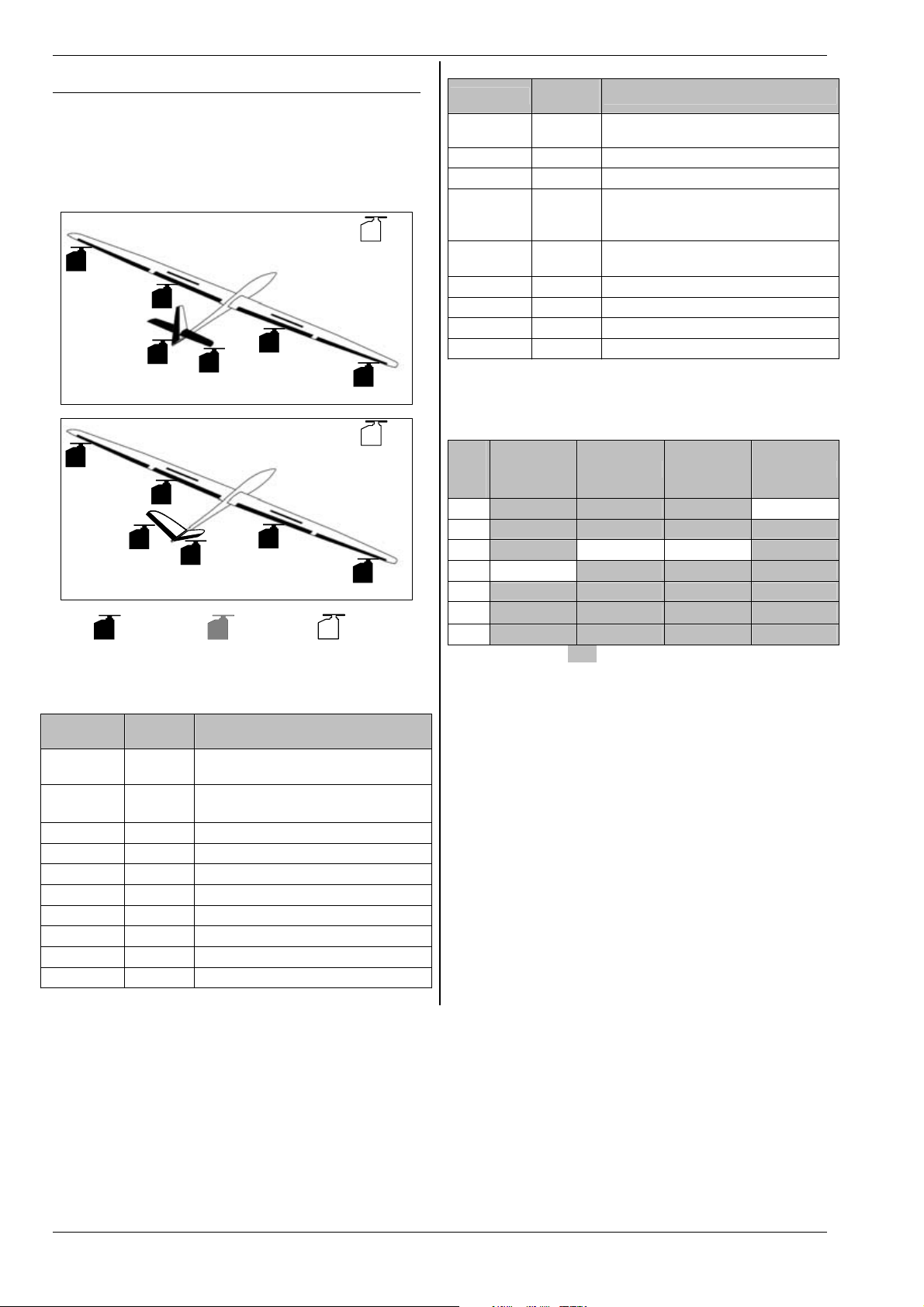
ROYAL evo 7
20.6. Template:4FLAPS
Suitable for gliders with four-flap wings, especially F3B
and F3J types, with normal tail (cruciform or T-tail) or Vtail, and options including aero-tow release or motor.
The model type includes flight phase switching.
Typical models: Milan, Euro/Elektro-Master, ALPINA,
ASW27B, DG600evo
p.ex.:
tow release,
AILERON+
FLAP+
FLAP+
FLAP+
assigned but
alterable
AILERON+
FLAP+
V-TAIL+
Rudder
fixed
assignment
ELEVATR+
V-TAIL+
20.6.1. Transmitter controls / switches
Name of assignment:
Control
Throttle E
Spoiler
Physical
control
‡
Stick
Note
Idle position = back
Can be altered (Î 13.3.3.)
Spoiler retracted = forward
Can be altered (Î 13.3.4.)
Flap F Control for camber-changing flaps
L-Gear
O Retract
Aero-tow G Aero-tow release
Brake G
Gyro E
Mixture F
AUX1
AUX2
L Auxiliary channel 1 (e.g. variometer)
G Auxiliary channel 2
spoiler,
retract
AILERON+
e.g.:
tow release,
spoiler,
retract
AILERON+
vacant
GLIDER
Switch
D-R
CS
THR-CUT
Physical
control
Dual-Rate switch for
L
aileron, elevator and rudder
N Combi-Switch
H EMERGENCY throttle CUT
Runs when slider E (THROTTLE) =
Timer E
forward
Can be altered (Î 17.)
SNAP/FLAP
Mix-1
Mix-2 G
Mix-3 L
Teacher
F-PH 1-3
Switch for SNAP-FLAP
I
Switch for A/B mixer (Î 9.2.)
Switch for A/B mixer (Î 9.2.)
Switch for A/B mixer (Î 9.2.)
M Trainer switch
J Flight phase switch
20.6.2. Servo assignment /
receiver output sequence
MPX Hitec Futaba JR
Chan
-nel
1 AILER.+ (L) AILER.+ (L) AILER.+ (L) ----2 ELEVATR+* ELEVATR+* ELEVATR+* AILER.+ (L)
3 Rudder* ----- ----- ELEVATR+*
4 ----- Rudder* Rudder* Rudder*
5 AILER.+ (R) AILER.+ (R) AILER.+ (R) AILER.+ (R)
6 FLAP+ (L) FLAP+ (L) FLAP+ (L) FLAP+ (L)
7 FLAP+ (R) FLAP+ (R) AILER.+ (R) FLAP+ (R)
Channels with a grey background cannot be changed!
Channels marked “-----“ can be assigned freely (Î 16.2.).
* automatically changes to
mixer is activated (=
ON)
V-TAIL+ if the V-Tail
(Î 15.1.).
Important: receiver socket sequence of wing servos
It is important to observe the stated connection sequence of the aileron servos, and the servos with an aileron input (AILERON+, FLAP+), at the receiver. The servos must always be connected alternately left (L) and
right (R) with rising channel numbers (1, 2, 3, …7), or in
the reverse order right (R) and left (L). If you neglect to
do this, the correct operation of aileron differential cannot be guaranteed.
Page 66
Page 68

H
20.6.3. Mixers
Mixer Input Note
V-tail mixer
V-tail
Combi
Switch
Ail.diff
ELEVATR+ Elevatr
Spoiler
Flap
Thr.-Tr
V-TAIL+ *
Rudder
Spoiler
Flap
Elevatr
Î 15.1.
Combi-Switch mixer
Î 15.2.
Aileron differential
Î 15.3.
Travel'
Travel# = Up-elevator travel
Elevator compensation for spoilers
(airbrakes):
Point1 = Elevator compensation
for half-extended spoilers
Point2 = Elevator compensation
for fully extended spoilers
Elevator compensation for flaps
(flaperons):
Travel' = Elevator compensation
for (e.g.) thermal setting
Travel# = Elevator compensation
for (e.g.) speed setting
Elevator compensation for throttle
(motor):
Point1 = Elevator compensation
for half-throttle
Point2 = Elevator compensation
for full-throttle
Travel'
Travel# = Up-elevator travel
Travel'
one direction (e.g. up)
Travel# = Rudder deflection in
the other direction (e.g. down)
It is possible to set up differential
rudder by setting different V-tail
travels up and down for rudder
commands. This means that a certain amount of up- or downelevator can be “mixed in” automatically when a pure rudder
command is applied. Generally this
takes the form of up-elevator, as a
little “up” is commonly required for
turning.
Elevator compensation for spoilers
(butterfly / crow setting):
Point1 = Elevator compensation
for half-extended spoilers
Point2 = Elevator compensation
for fully extended spoilers
Elevator compensation for flaps
(flaperons):
Travel' = Elevator compensation
for (e.g.) thermal setting
Travel# = Elevator compensation
for (e.g.) speed setting
= Down-elevator travel
= Down-elevator travel
= Rudder deflection in
ROYAL evo 7 - Instructions
Thr.-Tr
AILERON+ Aileron
Spoiler
Flap
Elevatr
-Tr
FLAP+ Aileron
Elevator compensation for throttle
(motor):
Point1 = Elevator compensation
for half-throttle
Point2 = Elevator compensation
for full-throttle
Maximum aileron travel when the
Aileron control is operated.
Travels = Symmetrical travels (
equal aileron travels up and down)
Aileron differential is adjusted in
the
Ail.diff mixer.
When the Spoiler control is oper-
ated (stick /
flect up to act as landing aid:
Off = Offset for aileron servos
(see notes below for calibrating AILERON+ servos on a four-flap wing
glider)
Travel = Aileron deflection at full
spoiler extension
When the Flap control (F) is operated both ailerons move up or
down to adjust the camber of the
wing section to optimise the model
for thermal and speed flying:
Travel' = Up-aileron travel for
(e.g.) speed flying
Travel# = Down-aileron travel for
(e.g.) thermal flying
When the elevator stick is operated,
both ailerons move up or down to
support the elevator response for
aerobatics (“snap-flap mixer”):
Travel' = Aileron movement
when down-elevator is applied
Travel# = Aileron movement
when up-elevator is applied
The mixer can be switched on and
off at any time using the "SNAPFLAP" mixer switch (= I).
Max. travel setting of camberchanging flaps when operating as
ailerons (opposed movement).
Travel' = Deflection of both flaps
in one direction (e.g. up)
Travel# = Deflection of both flaps
in the other direction (e.g. down)
Aileron differential can be set independently of the ailerons (using
Ail.diff.) if required by the
asymmetrical travel settings.
This input is switchable using the
switch “MIX / AUX2” (= G). The input may be mixed in for aerobatics
to improve the aileron response.
‡), both ailerons de-
ENGLIS
Page 67
Page 69

ROYAL evo 7
When you operate the Spoiler con-
trol (stick /
changing flaps deflect down to act
as landing aid:
Off = Offset for flap servos (see be-
low for notes on calibrating the AI-
Spoiler
Flap
Elevatr
-Tr
* appears only if the V-tail mixer is activated (= ON).
LERON+ servos for four-flap gliders.
Travel = Aileron deflection at full
spoiler extension.
If ailerons are set to deflect up
when spoilers are extended, the result is known as the Butterfly or
Crow landing system.
When the flap control (F) is operated, both camber-changing flaps
deflect up or down to alter the wing
camber in order to optimise the
wing section for thermal and speed
flying:
Travel' = Up-flap deflection, e.g.
for speed flying
Travel# = Do wn -f la p d ef le ct io n,
e.g. for thermal flying
The values should be set so that the
camber of the wing section is constant over the full wingspan, i.e. coordinated flap and aileron travels.
When the elevator stick is operated,
both flaps move up or down to
support the elevator response for
aerobatics (“snap-flap mixer”):
Travel' = Flap deflection when
down-elevator is applied
Travel# = Fl ap de fl ec ti on wh en
up-elevator is applied
The mixer can be switched on and
off at any time using the "SNAPFLAP" mixer switch (= I).
‡) both camber-
Note:
Special features when calibrating the following servos:
FLAP+ and AILERON+ (input: Spoiler, parameter:
Off = OFFSET)
Glider wings with four flaps can be set up to produce
the Butterfly or Crow landing system (max. aileron uptravel, max. flap down-travel). In this case the flap servos
in particular have a highly asymmetrical working range:
Maximum up-aileron travel is required (approx. 20°). For
landing the flaps should deflect down as far as possible
to obtain best possible braking effect (if possible > 60°).
The servo travel in the “up” direction must be greatly
reduced, unless you have installed the output arms on
the servos at an angle (mechanical differential). This
means that valuable servo travel is sacrificed, and servo
power is lost. Unnecessary gearbox play, reduced positional accuracy and increased gearbox shock loading in
a hard landing have to be accepted.
Page 68
Page 70
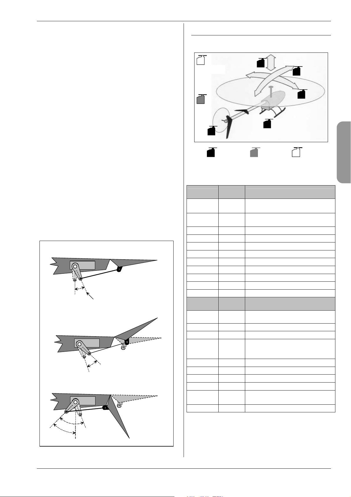
H
You can minimise these problems as follows:
1. Fit the servo output arm on the flap and aileron
servos at right-angles to the pushrods.
2. Determine the centre of the working range of the
control surface:
Example: the working range of the control surface
(e.g. flap) is +20° ... -60°, starting from the neutral
position (control surface in line with airfoil)
the centre of the working range of the control
surface is therefore at -10°.
Adjust the control surface pushrod so that the control surface is at -10° when the servo is at centre.
TIP:
When you select the servo in the
menu, select the percentage value for point
brate
P3 and then press the digi-adjustor assign button
< F >: the servo will then run to its exact neutral
point (Î 16.1.).
3. Both
FLAP+ and AILERON+ servos should now be
calibrated at points
P4 i f u se d) so th at bo th co nt ro l s ur fa ce s o n
and
P1, P3, and P5 (also points P2
each side line up exactly at all points (in our example at +20° / -10° / -60°).
4. Now adjust the
Off (offset) parameter of the
Spoiler input in the FLAP+ and AILERON+ mix-
ers so that the control surfaces follow the wing airfoil exactly.
The diagram below shows how this system works in
comprehensible graphic form:
Flap at neutral position,
servo offset by"Offset"
Off (Offset)
servo centre
Flap up-deflection,
e.g. for AILERON function
Flap deflection increased by "Offset",
for Butterfly / Crow
new servo neutral position
Offset + travel
Trvl
Servo / Cali-
ROYAL evo 7 - Instructions
20.7. Template: HELImech
Suitable for model helicopters with mechanical rotor
head mixing.
e.g.:
speed controller
Gyro
TAIL
20.7.1. Transmitter controls and switches
Name of assignment:
Control
Coll. pitch
Throttle
limit
Spoiler O
RPM G
L-Gear
Aero-tow G
Brake G
Gyro E Gyro gain adjustment
Mixture E
AUX1
AUX2
Switch
D-R
DTC
THR-CUT
Timer F
Mix-1 I
Mix-2 G
Mix-3 L
Teacher
A-ROT
F-PH 1-3
Collect.
Throttle
fixed
assignment
Physical
control
‡
Stick
F
assigned but
alterable
Note
Coll. minimum (descent) = back
Can be altered (Î 13.3.3.)
Thr. minimum (idle) = back
Can be altered (Î 13.3.4.)
Speed governor switch (Î 9.2.)
O Retracts
L Auxiliary channel 1
G Auxiliary channel 2
Physical
control
Dual-Rate switch for
L
roll, pitch-axis, yaw (tail rotor)
N Direct Throttle Control
H EMERGENCY throttle CUT
Runs when slider F (throttle limiter)
= forward
Can be altered (Î 17.)
Switch for A/B mixer (Î 9.2.)
Switch for A/B mixer (Î 9.2.)
Switch for A/B mixer (Î 9.2.)
M Trainer switch
Auto-rotation switch (activates
I
flight phase 4:
J Flight phase switch
Elevator
(pitch-axis)
Aileron
(roll)
vacant
HELI
AUTOROT)
ENGLIS
Page 69
Page 71

ROYAL evo 7
20.7.2. Servo assignment /
receiver output sequence
MPX Hitec Futaba JR
Chan
-nel
1 Roll Roll Roll Throttle
2 Pitch-axis Pitch-axis Pitch-axis Roll
3 TAIL Throttle Throttle Pitch-axis
4 Coll. pitch TAIL TAIL TAIL
5 Throttle Gyro Gyro ----6 Gyro Coll. pitch Coll. pitch Coll. pitch
7 ----- ----- ----- Gyro
Channels with a grey background cannot be changed!
Channels marked “-----“ can be assigned freely (Î 16.2.).
20.8. Template: HELIccpm
Suitable for model helicopters with CCPM electronic rotor head mixing (Cyclic-Collective Pitch Mixing), e.g. 3point 120°, 3-point 90°, 3-point 140°.
t
h
lig
f
e.g.:
speed controller
TAIL
Throttle
D
Gyro
f
o
n
o
i
t
c
e
ir
Runs when slider F (throttle limiter)
Timer F
= forward
Can be altered (Î 17.)
Mix-1 I
Mix-2 G
Mix-3 L
Teacher
A-ROT
F-PH 1-3
Switch for A/B mixer (Î 9.2.)
Switch for A/B mixer (Î 9.2.)
Switch for A/B mixer (Î 9.2.)
M Trainer switch
Auto-rotation switch (activates
I
flight phase 4:
AUTOROT)
J Flight phase switch
20.8.2. Servo assignment /
receiver output sequence
MPX Hitec Futaba JR
Chan
-nel
1 HEAD f/r HEAD ri HEAD le Throttle
2 HEAD le HEAD f/r HEAD f/r HEAD ri
3 TAIL Throttle Throttle HEAD f/r
4 HEAD ri TAIL TAIL TAIL
5 Throttle Gyro Gyro ----6 Gyro HEAD le HEAD ri HEAD le
7 ----- ----- ----- Gyro
Channels with a grey background cannot be changed!
Channels marked “-----“ can be assigned freely (Î 16.2.).
HEADri
fixed
assignment
HEAD f/b
HEAD le
assigned but
alterable
20.8.1. Transmitter controls and switches
Name of assignment:
Control
Coll. pitch
Throttle
limit
Physical
control
‡
Stick
F
Note
Coll. minimum (descent) = back
Can be altered (Î 13.3.3.)
Thr. minimum (idle) = back
Can be altered (Î 13.3.4.)
HELI
Spoiler O
RPM G
L-Gear
Speed governor switch (Î 9.2.)
O Retracts
Aero-tow G
Brake G
Gyro E Gyro gain adjustment
Mixture E
AUX1
AUX2
Switch
D-R
DTC
THR-CUT
L Auxiliary channel 1
G Auxiliary channel 2
Physical
control
Dual-Rate switch for
L
roll, pitch-axis, yaw (tail rotor)
N Direct Throttle Control
H EMERGENCY throttle CUT
vacant
Page 70
Page 72

H
21. Error messages
Every time you switch the transmitter on, the
ROYALevo7 checks the contents of its memory. If it detects an error, the following error message will appear:
Memory Error
If this should happen, do not use the transmitter, and
do not make changes to any settings.
The ROYALevo DataManager PC back-up and update
program (Î 23.1.) is capable of correcting many data
errors. To make use of this simply carry out a data backup procedure. The data error will be recognised by the
ROYALevo Data Manager:
If you confirm by clicking on “Yes”, but the error message occurs repeatedly, there is a serious data error. In
this case the cause is often a hardware defect (perhaps
caused by neglecting the battery charging instructions,
or using an unsuitable or faulty charger). The transmitter must then be sent to a MULTIPLEX Service Centre
for checking and repair.
Important: please check the version of ROYALevo
DataManager you are using.
For the ROYALevo 7 a later version of the ROYALevoDataManager is required than is current at the time of
printing of these instructions (V1.06).
22. Accessories
22.1. HFM-4 crystal RF module
# 4 5690 35 MHz A- and B-band
# 4 5691 40/41 MHz band
# 4 5697 36 MHz
#4 5692 72 MHz
Reasonably priced RF modules using conventional crystal technology. Be sure to use genuine MULTIPLEX plugin crystals.
Important: which channels can be used?
Regulations concerning the use of radio-controlled
models vary from country to country. Please make enquiries to establish which RF module you should use,
and which channels are approved for the region in
which you wish to fly your models.
ROYAL evo 7 - Instructions
22.2. Channel-Check module for HFM-4
crystal RF module
# 7 5164 35MHz A- and B-band (also for 36MHz)
# 7 5165 40/41MHz band
The Channel-Check module is simply plugged into the
HFM-4 crystal RF module, and is easy to
install at any time. The Channel-Check
module requires a receiver crystal (MULTIPLEX single-conversion crystal) whose
channel / frequency is the same as the
transmitter crystal you are using. When
you switch the transmitter on, the module checks whether the transmission
channel is in use, and only switches the
Channel-Check
module
RF module on if it is vacant. In this way it
guards against frequency clashes and makes an important contribution to safety in model sport.
Retro-fitting the module
1. Switch off and open the transmitter
2. Remove the HFM-4 RF module
3. Plug the receiver crystal into the
Channel-Check module
4. Plug the Channel-Check module
into the RF module
5. Re-install the RF module
Operation
1. Extend the transmitter aerial to full length
2. Switch on the transmitter
3. The RF status LED flashes:
the channel is free (no guarantee), the RF module
is immediately activated, and the transmitter is
ready to use. “No guarantee” means that the module
may not be able to detect distant transmitters
(approx. > 300 m) because of the influence of environmental conditions and the local terrain. However, if the model should fly close to such a transmitter, there is then a risk of interference due to a channel clash.
4. RF status LED glows constantly channel in use
The screen also displays the following message for
two seconds:
!Attention! No RF
If Channel-Check finds the channel to be in use
when switched on, you must switch the transmitter
off again before you can use it. Check whether your
channel is already in use by another modeller (including transmitters a long way away!). If this is not
the case, the problem may be a transmitter in the
immediate vicinity on an adjacent channel, momentary interference on the channel when you switched
on, etc. Before you switch on again, walk a little way
away from other transmitters, then try again.
22.3. HFM-S Synthesizer RF module
# 4 5693 35 MHz A- and B-band
# 4 5694 40/41 MHz band
# 4 5696 36 MHz
# 4 5695 72 MHz
RF modules exploiting modern Synthesizer technology.
The transmission channel can be selected quickly and
conveniently in the channel set-up menu. No plug-in
crystals are required at the transmitter.
Important: which channels can be used?
Regulations concerning the use of radio-controlled
models vary from country to country. Please make en-
Page 71
ENGLIS
Page 73

ROYAL evo 7
quiries to establish which RF module you should use,
and which channels are approved for the region in
which you wish to fly your models.
22.4. Scanner for HFM-S Synthesizer RF
module
# 4 5170 35 MHz A- and B-band
# 4 5171 40/41 MHz band
# 4 5173 36 MHz
# 4 5172 72 MHz
Important: which channels can be used?
Regulations concerning the use of radio-controlled
models vary from country to country. Please make enquiries to establish which RF module you should use,
and which channels are approved for the region in
which you wish to fly your models.
The scanner allows you to monitor the frequency band,
and guards against channel clashes. The Scanner module is simply plugged into the HFM-S Synthesizer RF
module, and is easy to fit at any time.
The scanner can carry out two tasks:
Checking your channel at power-on (Channel-Check)
The channel you select for the Synthesizer is checked
when you switch the transmitter on. If the channel is already in use, the Synthesizer stays switched off, and the
user is alerted to the situation by an on-screen warning.
If the scanner picks up no signal during this check, the
transmitter switches itself on in the normal way.
Scanning the whole frequency band
The scanner checks all channels of the frequency band
one by one. All the signals it detects are displayed in bar
graph form on the screen; the height of the bar indicates the signal strength.
Detailed instructions for using the Scanner module for
the HFM-S Synthesizer RF module are supplied with the
module itself.
22.5. Trainer lead
# 8 5121
The ROYALevo7 can be used either as Teacher or Pupil
transmitter in a Trainer (buddy-box) system.
Any MULTIPLEX transmitter fitted with a 5-pin DIN
socket (MULTIPLEX multi-function socket) can be used
as a pupil transmitter. (Î 13.4.)
22.6. Diagnosis lead
# 8 5105
For carrying out adjustments to the model the receiver
can be operated in Diagnosis mode (DSC - Direct Servo
Control) via a cable, without the transmitter radiating an
RF signal, even if “your” channel is already in use. Connect the transmitter (MULTIPLEX multi-function socket)
to the receiver (charge socket on the switch harness
# 8 5039 or # 8 5046) using the Diagnosis lead. Please
note: Diagnosis mode is only possible with MULTIPLEX
receivers which feature a combined Battery / Diagnosis
socket marked “B/D”.
22.7. Other accessories, spareparts
Item
Transmitter case
Standard transmitter aerial, 110 cm
Transmitter tray
SpaceBox ROYALevo Basic transmitter
tray
SpaceBox ROYALevo weather guard (op-
tional)
PROFI transmitter neckstrap
Neckstrap padding for # 8 5646 # 8 5641
“Cross-over” transmitter support strap
PC lead (Î 23.)
Receiver module for the MULTInaut IV
channel expansion system (Î 24.)
For more information on accessories and replacement
parts please refer to the current main catalogue or our
internet website www.multiplexrc.de.
23. PC interface
The multi-function socket on the underside of the
ROYALevo transmitter provides a serial interface to a PC
in addition to the functions of charging, Trainer mode
and Diagnosis mode. This interface offers two functions:
x access to transmitter data
for data back-up, software update
x use with model flying simulators
23.1. Software update / data back-up
The facility to exchange data between transmitter and
PC provides the following possible functions:
x Data back-up
storing (backing-up) model memory data on your PC
x Software update (loading new software into the
transmitter)
The latter point in particular enables you to exploit entirely new methods of updating the transmitter software or installing new screen languages via the internet. The PC software “ROYALevo DataManager“ and current software updates in various national languages are
already available in the Download area of our internet
website: www.multiplexrc.de.
Important: please check the version of ROYALevo
DataManager you are using.
For the ROYALevo 7 a later version of the ROYALevoDataManager is required than is current at the time of
printing of these instructions (V1.06).
The connecting lead (PC lead # 8 5156) is available from
your local model shop.
23.2. Using a flight simulator
The ROYALevo7 can be used directly with many flight
simulators, without further expansion. The manufacturers of flight simulators offer special interface cables
for MULTIPLEX transmitters. If you have a query, please
address it to the simulator manufacturer.
Page 72
# 76 3323
# 89 3002
# 8 5305
# 8 5658
# 8 5655
# 8 5646
# 8 5640
# 8 5156
# 7 5892
Page 74

H
24. MULTInaut IV
channel expansion system
If the seven channels of the ROYALevo 7 are not sufficient, perhaps for a complex multi-function model, the
MULTIPLEX MULTInaut IV channel expansion system
can be used. The ROYALevo is capable of controlling
two MULTInaut IV receiver modules (# 7 5892) which
are available as optional accessories.
Each MULTInaut IV receiver module installed in the
model can control up to four consumer units (max. continuous load 4 x 4A / 16V) and/or up to four servos in
various modes of operation. One channel is required to
actuate one MULTInaut IV receiver module. If you use
two MULTInaut IV receiver modules a total of 13 channels are available to you (five proportional channels plus
2 x 4 MULTInaut channels).
Preparation
Move to the menu
and determine which channels (receiver outputs) are to
be used for the control signals of the two MULTInaut IV
receiver modules:
M.naut1 or M.naut2
The receiver modules in the model must be connected
to the corresponding channels.
Servo / Assignment (Î 16.2.)
ROYAL evo 7 - Instructions
The effect of one button-press varies according to the
system controlled by the MULTInaut channel. The following alternatives are available:
a. Consumer units to terminals +/-1 to +/-4
The diagram shows where the consumer units
have to be connected.
Diagram for servo 5 =
For switching consumers (e.g. lamps, horns etc.).
Every time you press a button briefly the associated load is switched from one state to the other:
(OFF Æ ON or ON ÆOFF)
M.naut1
ENGLIS
The MULTInaut system is only available for the
fixed-wing model type!
Activating the MULTInaut mode of operation:
The keypad of the ROYALevo is used to control the
MULTInaut functions (no additional or special switches
have to be installed). Starting from one of the three
status displays, hold the ENTER button held in for
longer than three seconds; this activates the button
groups for MULTInaut use. The screen display is as follows:
Note:
If the MULTInaut mode of operation is active and the
MULTINAUT display is on the screen, it is not possible to
use the keypad (or the 3D digi-adjustors) to make
changes in any of the menus.
Hold ENTER pressed in again for longer than three sec-
onds to end this mode of operation.
Operating the MULTInaut channels
In each case four buttons (group of buttons) are assigned to one MULTInaut channel, and control the consumer units or servos connected to the receiver module.
e.g. servo 5 = M.naut 1
b. Servo to sockets 1 to 4, no jumper
If the jumpers (bridging plugs) are not connected
to servo sockets 2 and 4, the servo moves from one
end-point to the other every time you press the associated button.
c. Servo to socket 1 / 3
to servo socket 2 / 4 with jumper
Buttons 1 and 2 control the servo at socket 1; buttons 3 and 4 the servo at socket 3. For as long as
the button is held pressed in the servo runs in one
direction until it reaches the end-point. When you
release the button, the servo stops.
The full servo travel is divided into 32 segments,
and takes about four seconds to traverse. One
short button-press triggers a step of about 3°.
Each MULTInaut IV module is supplied with detailed
operating instructions including all the information you
need to install and operate the system, together with a
full Specification.
Button group for
M.naut 1
Page 73
Page 75

ROYAL evo 7
25. Care and maintenance
The transmitter requires no special care or maintenance.
However, we strongly recommend that you send the
transmitter to an authorised MULTIPLEX Service Centre
at regular intervals - depending on the frequency of use
- for a full check; this should take place every two or
three years. Regular operating checks and range checks
(Î 3.2.) should be considered mandatory.
The bes t wa y of remo vin g du st a nd d irt is to use a so ft
bristle paintbrush. More stubborn soiling, especially by
grease and oil, should be removed using a soft cloth
dampened with a mild household cleaner. Never use
powerful cleaning agents such as white spirit or solvents.
Avoid subjecting the transmitter to shock and pressure
loads. The unit should always be stored and transported
in a suitable container (transmitter case or bag).
Check the transmitter case, mechanical assemblies and especially - cables and connector contacts regularly.
! Always switch off the transmitter before open-
ing the case, and disconnect the transmitter
battery before carrying out any internal work.
Avoid touching electrical components and circuit boards.
26. Advice and customer service
We have invested considerable effort in making these
operating instructions as comprehensive and comprehensible as possible, so that you can locate the answer to any question quickly and easily. However, if you
have a question on your ROYALevo 7 which the manual
cannot answer, please ask your local model shop in the
first instance, where the staff will be glad to advise and
help you.
If you encounter a technical problem you can call our
Hotline: +49 7233 7343
For repairs and servicing please contact your nearest
authorised MULTIPLEX Service Centre.
Germany
MULTIPLEX Service
Neuer Weg 15 • D-75223 Niefern
+49 (0)7233 / 73-33
Fax. +49 (0)7233 / 73-19
e-mail service@multiplexrc.de
Austria
MULTIPLEX Service Heinz Hable
Seppengutweg 11 • A-4030 Linz
+43 (0)732 / 321100
Switzerland
MULTIPLEX Service Werner Ankli
Marchweg 175 • CH-4234 Zullwil
+41 (0)61 / 7919191
+41 (0)79 / 2109508
Switzerland
RC-Service Basel K. Elsener
Felsplattenstraße 42 • CH-4012 Basel
+41 (0)79 / 3338282
France
MULTIPLEX Service Hubscher Electronic
9, rue Tarade • F-67000 Strasbourg
+33 (0)388 / 411242
Italy
Holzner & Premer OHG-Snc. • c/o Robert Holzner
Prission 113 • I-39010 Trisens BZ
Tel. +39 (0)473 / 920887
Netherlands
MULTIPLEX Service • Jan van Mouwerik
Slot de Houvelaan 30 • NL-3155 VT Maasland
+31 105913594
Belgium
MULTIPLEX Service • Jean Marie Servais
Rue du Pourrain 49 A • B-5330 Assesse
+32 (0)836 / 566 620 4
+32 (0)495 / 534 085
Sweden
ORBO elktronik/hobby ab
Box 6021 • S-16206 Vällingby
+46 (0) 8 832585
U.K.
Michael Ridley c/o Flair Products Ltd
Holdcroft Works • Blunsdon SN26 7AH
07708436163
Spain
Condor Telecomunicaciones y Servicios S.L.
Centro Comercial Las Americas
Avenida Pais Valencia 182
Torrente 46900
96 - 1560194
Australia
David Leigh
64 Koongarra Ave • Magill 5072, South Australia
08 - 8332 2627
+41 (0)61 / 3828282
Page 74
Page 76
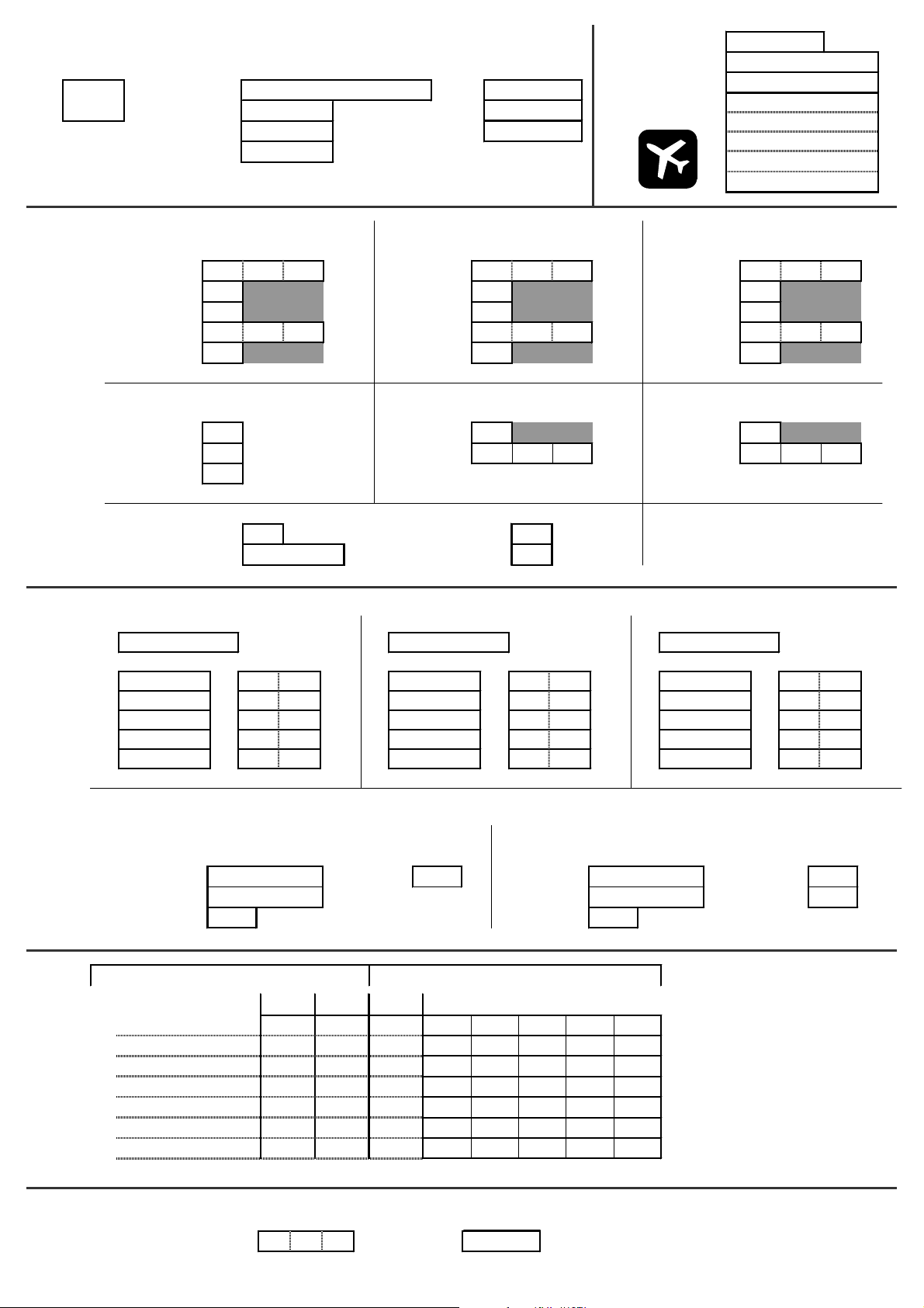
s
s
Memory
e
s
number
Memory
Properties
I
Name
Template
Mode
Assignment
Flight phas
I
1
2
3
Date
Template
Servo conf.
Notes
New model
Aileron
H
Trim % Trim % Trim %
Step
Control
D/R
Trvl % Trvl % Trvl %
Expo
Throttle
H
Idle % Slow
Step % Fixed val % Fixed val %
Slow s
L
Mode Throttle min
Assignment Spoiler min
Name Name Name
GGG
Input Input Input
Mixer
Flight phase
Geber
Elevator
H
123
Å
Å
Å
Value Value Value
% Step
% D/R
% Expo
Flight phase
Spoiler
H
Flight phase
123
Å
Å
Å
% Step
% D/R
% Expo
123
Å
s Slow
Rudder
H
Flight phase
Flap
H
Flight phase
%%%
%%%
%%%
%%%
%%%
123
Å
Å
Å
123
Å
%
%
%
s
Free Mixers A and B
Mixer A/B
L
Mixer A Mixer B
Control Travel % Control Travel+ %
Servo Servo Travel- %
Switch Switch
Assignment
K
Nr. Function
1 %
Servo
2 %
3 %
4 %
5 %
6 %
7 %
Timer
MixerA
G
MPX/UNI Points rev./nor.
Timer
A
Alarm Switch
hms
Mixer A/B
L
Calibrate
K
P1 P2 P3 P4 P5
MixerB
G
Page 77

s
s
Memory
e
s
number
Memory
Properties
I
Name
Template
Mode
Assignment
Thr-curve
Flight phas
I
1
2
3
AUTOROT
4
Date
Template
Servo conf.
Notes
New model
Aileron
H
Flight phase
1234
Elevator
H
Flight phase
1234
Rudder
H
Flight phase
1234
Trim % Trim % Trim %
Step
D/R
Trvl % Trvl % Trvl %
Control
Expo
Control
L
Å
Å
Å
Mode
% Step
% D/R
% Expo
Collect.
H
Flight phase
Å
Å
Å
% Step
% D/R
% Expo
1234
Throttle
H
Flight phase
Å
Å
Å
%
%
%
1234
Assignment % P1 % P1 %
% P2 % P2 %
Coolect. Min % P3 % P3 %
Thr.lim. min % P4 % P4 %
% P5 % P5 %
% P6 %
Gyro
G
Mode
Flight phase
1234
Damping %
Suppression
Mixer
Å
TAIL
G
Flugphase
1234
Coll.+ %
Coll.- %
Yaw diff. %
%
Rotor head
G
Geometry °
Rotation °
Offset %
Zero point
Collect.
Å
Nur Anzeige!
%
Free Mixers A and B
Servo
Timer
Mixer A/B
L
MixerA
G
Mixer A/B
L
MixerB
G
Mixer A Mixer B
Control Travel % Control Travel+ %
Servo Servo Travel- %
Switch Switch
Assignment
K
Nr. Function
MPX/UNI Points rev./nor.
P1 P2 P3 P4 P5
Calibrate
K
1 %
2 %
3 %
4 %
5 %
6 %
7 %
Timer
A
Alarm Switch
hms
 Loading...