

Page 1
M U L T I P L E X
Instructions
M o d e l l t e c h n i k G m b H
© M U L T I P L E X 2 0 0 2
N e u e r W e g 1 5
l
, P r i n t e d i n G e r m a n y
D - 7 5 2 2 3 N i e f e r n
l
l
G e r m a n y
Page 2
1. Contents
1. Contents 57
2. Introduction 59
3. Safety notes 59
3.1. General safety notes 60
3.2. Range checking 61
4. Liability / Compensation 62
5. Guarantee 62
6. Specification 62
7. The transmitter 63
7.1. Front face of transmitter 63
7.2. Rear face of transmitter 63
7.3. Inside the transmitter 64
7.4. Mechanical details 64
7.4.1. Opening and closing the transmitter case 64
7.4.2. Adjusting the transmitter aerial,
fitting a new aerial 65
7.4.3. Installing and removing the RF module 65
7.4.4. Changing the transmitter crystal
(HFM-4 module only) 66
7.4.5. Changing the transmitter battery 66
7.4.6. Disabling the stick neutralisation system,
installing the spring for ratchet or friction
operation 66
7.4.7. Adjust the neutralising force 66
7.4.8. Swivelling the stick units 67
7.4.9. Adjusting and replacing the stick tops 67
7.4.10. Stick top with buttons
- how to fit them, how they work 67
7.4.11. Installing the optional switches “P” and “K” 68
8. The transmitter battery 68
8.1. Battery management in the ROYALevo 68
8.1.1. This is what we have already 68
8.1.2. This is NEW 69
8.1.3. This is what you must attend 69
8.2. The essentials in brief 69
8.3. Safety notes 69
8.4. Charging the transmitter battery 70
8.5. Maintaining and storing
the transmitter battery 70
8.6. Recycling 70
9. Using the transmitter 71
9.1. Switching on for the first time 71
9.2. The power-ON procedure 71
9.2.1. Switching ON
with the HFM-4 RF module for crystals 71
9.2.2. Switching ON
with the HFM-S synthesizer RF module 71
9.2.3. Switching ON
without transmitting an RF signal 71
9.3. Security queries when switching ON 72
9.3.1. Throttle check 72
9.3.2. RF Check with the synthesizer module 72
9.4. Selecting the channel with an HFM-S
synthesizer RF module 72
9.5. The RF status display (red LED) 72
9.6. The status displays 73
10. The basic operating philosophy 74
10.1. The keypad 74
10.1.1. Direct menu access buttons (row 1) 74
10.1.2. Task buttons (row 2) 74
10.1.3. Text input 74
Instructions
10.2. The 3-D digi-adjustors 75
10.2.1. Programming
using the 3-D digi-adjustors 75
10.2.2. Making adjustments
using the 3-D digi-adjustors 75
10.3. Working with the keypad and 3-D digi-
adjustor -the fundamental operating
philosophy 75
10.3.1. Calling up main menus 75
10.3.2. Opening sub-menus 76
10.3.3. Changing values 76
10.3.4. Returning from whence you came 77
11. Digital trims 77
11.1. Introduction 77
11.2. Advantages of digital trims 77
11.3. The cruciform digital trim assembly 78
11.4. On-screen trim display 78
12. Creating a new model 78
12.1. Basic information 78
12.2. A new fixed-wing model 78
12.3. A new helicopter 79
12.4. Model templates in detail 83
12.5. Template: BASIC 83
12.5.1. Assigned transmitter controls and switches 83
12.5.2. Assigned servos / receiver outputs 83
12.5.3. Fine-tuning 83
12.6. Template: ACRO 84
12.6.1. Assigned transmitter controls and switches 84
12.6.2. Assigned servos / receiver outputs 84
12.6.3. Fine-tuning 84
12.7. Template: HOTLINER 84
12.7.1. Assigned transmitter controls and switches 84
12.7.2. Assigned servos / receiver outputs 84
12.7.3. Fine-tuning 84
12.8. Template: DELTA 85
12.8.1. Assigned transmitter controls and switches 85
12.8.2. Assigned servos / receiver outputs 85
12.8.3. Fine-tuning 85
12.9. Template: GLIDER 85
12.9.1. Assigned transmitter controls and switches 85
12.9.2. Assigned servos / receiver outputs 85
12.9.3. Fine-tuning 85
12.10. Template: 4-Flaps 86
12.10.1. Assigned transmitter controls and switches 86
12.10.2. Assigned servos / receiver outputs 86
12.10.3. Fine-tuning 86
12.11. Template: HELImech 86
12.11.1. Assigned transmitter controls and switches 86
12.11.2. Assigned servos / receiver outputs 86
12.11.3. Fine-tuning 86
12.12. Template: HELIccpm 87
12.12.1. Assigned transmitter controls and switches 87
12.12.2. Assigned servos / receiver outputs 87
12.12.3. Fine-tuning 87
13. Main menu „Setup“ LL 87
13.1. Sub-menu „Transmitter“ 87
13.1.1. Parameter „Trim graphics“ 87
13.1.2. Parameter „Sounds“ 87
13.1.3. Parameter „Battery alarm“ 87
13.1.4. Parameter „Battery charge“ 88
13.1.5. Parameter „Contrast“ 88
13.1.6. Parameter „ Check throttle “ 88
13.1.7. Parameter “Check RF” 88
Page 57
Page 3

ROYAL evo
13.2. Sub-menu “Define mixer” 88
13.2.1. How the freely definable mixers work 88
13.2.2. Defining mixers 89
13.2.3. The mixer options 89
13.3. Sub-menu “Assignment” 90
13.3.1. Parameter „Mode“ 91
13.3.2. Parameter „Assignment“ 91
13.3.3. Parameter „Assignment - Name“ 91
13.3.4. Parameter „Assignment - Controls“ 91
13.3.5. Parameter „Assignment - Switches“ 92
13.4. Sub-menu “Training” 92
13.4.1. Teacher/pupil operation 92
13.4.2. The ROYALevo as Teacher transmitter 92
13.4.3. The ROYALevo as pupils transmitter 93
13.5. Sub-menu “User” 93
13.5.1. Parameter „PIN“ 93
13.5.2. Parameter „Language“ 93
13.5.3. Parameter „Name“ 93
14. Main menu „Controls“ HH 93
14.1. Sub-menu „Control switch“ 93
14.2. Sub-menus for individual controls 94
14.2.1. Control settings for the primary axes 94
14.2.2. Parameter „Trim“ 95
14.2.3. Parameter „Step“ (trim increment) 95
14.2.4. Parameter „D/R“ (Dual-Rates) 95
14.2.5. Parameter „Trvl“ 95
14.2.6. Parameter „Expo“ 95
14.2.7. Parameter „Fixed value“ 95
14.2.8. Parameter „Run time“ (Slow) 95
14.2.9. Parameter „Idle“ (idle trim) 95
14.2.10. Parameter „Collective pitch“
14.2.11. Parameter "Throttle" (Throttle curve) 96
14.2.12. Parameter „RPM“ speed regulators 96
(Coll. pitch curve) 95
15. Main menu „Mixers“ GG 97
15.1. Sub-menu „Combi-Switch“ 97
15.2. Sub-menu „A-Diff“ (aileron differential) 97
15.2.1. Parameter „Mode“ 97
15.2.2. Parameter „Diff.“ 97
15.3. Submenu „Gyro“ 97
15.3.1. Parameter „Mode“ 98
15.3.2. Parameter „Heading / Damping“ (Gyro gain) 99
15.3.3. Parameter „Suppression“ 99
15.4. Sub-menu „Tail rotor“ (static tail rotor
compensation/Revo-Mix) 99
15.4.1. Parameter „Collective Pitch+ and -“ 100
15.4.2. Parameter „Yaw diff.“ 100
15.4.3. Parameter „Offset“ 100
15.4.4. Parameter „Zero point“
and Coll.Pitch display 100
15.5. Sub-menu „Rotor head“
(electronic swashplate mixer/CCPM) 100
15.5.1. Parameter „Geometry“ 101
15.5.2. Parameter „Rotation“ 101
15.5.3. Parameter „Lever +/-“ 101
15.5.4. Helicopters HEIM mechanics 101
15.6. Sub-menu „Throttle compensation“ 102
15.6.1. Parameter „Rudder“ (Yaw) 102
15.6.2. Parameter „Aileron“ (Roll) 102
15.6.3. Parameter „Elevator“ (Pitch axis) 102
15.7. Setting up “free mixers” 102
16. Main menu „Servo“ KK 103
16.1. Sub-menu „Calibrate“ 103
16.1.1. Parameter „REV/TRM“ 103
16.1.2. Parameter „P1 … P5“ 104
16.2. Sub-Menu „Assignment“ 104
16.2.1. Special: MULTInaut IV 105
16.2.2. Assigning servos for fixed wing models 105
16.2.3. Assigning servos for helicopters 106
16.3. Sub-menu „Monitor“ 106
16.4. Sub-menu „Test run“ 106
17. Main menu „Timer“ AA 107
17.1. Sub-menu „Model“ 107
17.2. Sub-menu „Slot“ 107
17.3. Timer „´ Sum“ 107
17.4. Sub-menu „¶¶ Interval“ 107
18. Main menu „Memory“ II 108
18.1. Sub-menu „Select model“
(change memory) 108
18.2. Sub-menu „Copy“ 108
18.3. Sub-menu „Erase“ 108
18.4. Sub-menu „Flight phases“ 108
18.4.1. Selecting flight phase names 108
18.4.2. Block / release flight phase 109
18.4.3. Copying the active flight phase 109
18.5. Sub-menu „Properties“ 109
18.6. Sub-menu „New model“ 109
19. Accessories 110
19.1. Scanner
(with HFM-S RF module) 110
19.1.1. Scan all frequencies/channels in the band 110
19.1.2. Channel-Check at power-ON 110
19.1.3. Installation of the scanner module 110
19.2. Channel-Check
(with the RF module HFM-4) 110
19.2.1. Installation of the Channel-Check module 110
19.2.2. Operating Channel-Check 110
19.3. Other accessories/spar parts 110
19.3.1. Overview 110
19.3.2. Stick top button/switch 110
19.4. Using MULTInaut IV 111
19.5. Diagnosis lead 111
19.6. PC interface 111
19.6.1. Accessing transmitter data 111
19.6.2. Flight simulator operation 111
20. Care and maintenance 112
21. Service and Support 112
Page 58
Page 4
Instructions
2. Introduction
We are delighted that you have decided to purchase the
MULTIPLEX ROYALevo radio control system. The
ROYALevo was introduced early in 2002, and constitutes
a modern digital radio control system, which represents
a further milestone in the development of radio control
systems by MULTIPLEX. In the overall design, development and production of this system we have invested
all our experience of several generations of radio control equipment. The result is a universal, ergonomically
efficient radio control system of modern design which is
simple to operate, and which is suitable for use both
hand-held and in a transmitter tray. And - not least - the
ROYALevo is MADE IN GERMANY.
We placed particular emphasis on convenience of operation during the development of the system software.
The ROYALevo offers you a wide range of functions
selected by experienced users, and these cope effortlessly with any model from simple two-axis gliders to
complex large-scale models and helicopters. Despite its
comprehensive features, the transmitter is simple to
operate and easy to understand.
The essential features of the ROYALevo are as follows:
• Ergonomically efficient case, suitable for hand-held
or tray use, with precision stick units which swivel
to suit your personal preference
• Graphical folding screen (132 x 64 pixels) with variable
contrast
• Easily accessible digital trims in a cruciform arrange-
ment, giving an entirely new feeling to the trims
• Low-cost standard RF module* with plug-in crystals, or
synthesizer RF module* with software channel selection
• 9 or 12 channels
• 20 or 36 model memories
• 6 menu buttons for fast, direct access to the main
menus
• 5 function buttons and two 3-D digi-adjustors for user-
friendly programming
• Detailed menu texts, selectable language, various lan-
guages available
• Comprehensive set-up and mixer facilities for fixed-wing
models and helicopters
• Sample models (templates) minimise programming
effort required
• Unrestricted assignment of transmitter controls,
switches and servos
• 4 flight phases per model memory
• 5 timers
(3 alarm timers + transmitter and model times)
• Facilities for selective Teacher/Pupil (Trainer) operations
as standard
We are confident that you will quickly learn to appreciate the ROYALevo, and enjoy using it to control your
models over a period of many years. Please take a little
while to familiarise yourself with the system, referring
constantly to these instructions which are intended to
help you.
Yours – the MULTIPLEX team
Options:
* MULTIPLEX Channel-Check power-on guard system
** Scanner with power-on guard function
Se e the main MULTIPLEX catalogue for frequency ranges available.
3. Safety notes
! These operating instructions are an integral part
of the product, and contain important information and safety notes. They should therefore be
stored in a safe place where you can refer to
them at any time. If you ever dispose of the
equipment be sure to pass on the instructions to
the new owner.
! Read these safety notes!
Read the instructions carefully! Please do not attempt to use the equipment until you have read
these operating instructions thoroughly, together with the following safety notes (included
in these instructions or supplied separately).
! It is not permissible under any circumstances to
make technical modifications to the radio control
system itself or its components. Use genuine
MULTIPLEX accessories and replacement parts
exclusively (especially transmitter battery, crystals, aerial, ...).
! If you wish to use the system in conjunction with
products made by other manufacturers, it is up
to you to carry out checks to ensure their quality
and compatibility. Every time you make any
change to the system, carry out a careful check of
the functions, and check the effective range.
Don’t operate the system or the model if you are
not sure everything is working correctly; first locate the fault and eliminate it.
! Warning!
Radio-controlled models are not playthings in
the usual sense. Building these models, installing
the RC system, and operating them all demand
technical knowledge, due caution and a responsible, safety-conscious approach. If you are negligent or make mistakes, the result may be serious damage and injury. As manufacturers, we
have no control over your methods of building
and operating any model, so all we can do is
point out these hazards expressly. We deny all liability.
! A model, which is out of control, for whatever
reason, is capable of causing serious personal injury and damage to property. It is essential that
you should take out suitable third-party insurance, so that you are covered if, in spite of all
your care, an accident should occur.
! Always keep to the following sequence when
switching the equipment on and off, as this avoids the danger of an electric power system
bursting into life unexpectedly:
1. When switching on:
Transmitter ON first,
then receiver ON.
Connect flight battery and switch power system
ON
2. When switching off:
First disconnect flight battery and switch power
system OFF
Receiver OFF
Transmitter OFF
Page 59
Page 5

ROYAL evo
mAhservosofNomAhCapacity
! We recommend that you have your radio control
system transmitters and receivers checked at
regular intervals (every 2 to 3 years) by an
authorised MULTIPLEX Service Centre.
! If any electrical device gets damp or wet, cease
operations immediately and disconnect the
power supply from it. Open the case if possible
and allow the unit to dry out thoroughly - preferably for several days. After this carry out a very
careful check of all the functions. If you are not
certain that all is well, send the unit to an authorised MULTIPLEX Service Centre for checking
! The operation of this radio control system is ap-
proved for use on particular channels / transmitter frequencies which vary from country to country. In some cases there are formalities such as
registration to be completed before you may use
the system. Please read the notes which are supplied with this set on a separate sheet.
3.1. General safety notes
When building the model:
• All control surfaces and linkages must be installed
and set up in such a way that the control surfaces
move with complete freedom, and do not tend to
bind or move stiffly at the extremes of travel. Do
not limit the servo travel from the transmitter; it is
always better to adjust the servo output arms,
horns and pushrods instead. Always aim at minimum possible lost motion (slop) in any linkage. All
these points help to minimise the load on the servos, ensuring that their maximum performance is
available to you, and that they will last as long as
possible. This also means maximum reliability and
safety for you and your models.
• Receiver, battery, servos and other RC components
and electronic units should be effectively protected
from vibration to avoid the danger of failure of any
electronic component. All the individual items are
supplied with operating instructions, and these
should be read thoroughly. Standard methods of
avoiding vibration include balancing propellers and
rotor blades before use, replacing damaged blades,
installing glowplug and petrol engines with effective vibration damping, replacing or repairing damaged motors and engines if they do not run
smoothly, and so on.
• Don’t place cables under tension, and don’t bend
them tightly; protect all leads from rotating parts.
• Keep servo leads as short as possible, and don’t use
them unless absolutely necessary. If you must use
extension leads which are 30 - 50 cm or more in
length, fit a separation filter (ferrite ring) in each
lead, and ensure that the conductors are of adequate cross-section to avoid voltage drop. We recommend at least 0.3 mm².
• Don’t coil up the receiver aerial, and do not shorten
it. Never deploy the aerial parallel to conductive
components such as metal pushrods, or inside a fuselage which has a shielding effect, i.e. made of or
reinforced with carbon fibre, or finished in metallic
paint. Don’t deploy the aerial on top of electrically
conducting model components. For large-scale
models we recommend the use of a whip aerial.
• Ensure that the receiver power supply is of ade-
quate capacity. If you are using servos rated at up to
about 40 Ncm you can calculate the required battery capacity using the following rule of thumb:
200.][ ×≥
If you have no problems with weight or space, it is
always better to select the next larger size of battery.
• Avoid any situation in which parts made of conduc-
tive material (e.g. metal linkage components or
pushrods) are in contact with each other, and move
against each other. This causes what is known as
electrical “noise”, which can interfere with the receiving system.
• Avoid interference pulses due to static charges or
powerful electric or electro-magnetic fields by taking appropriate suppression measures. These include suppressing electric motors with suitable capacitors, using shielded plug caps, ignition leads
and ignition units with spark-ignition petrol engines; keeping the RC system components, including aerial, wiring and batteries, well away from the
ignition circuit.
• Keep the receiving system a safe distance from
high-current leads (e.g. electric power system wiring). High-current cables, especially those between
brushless electric motors and their controllers,
should be as short as possible (guide: max. 10 - 15
cm).
• When you have completed a new model, carry out
the programming of your transmitter in the peace
and quiet of your home. Check all the functions carefully before flying the model. Take the time to
familiarise yourself with the programming procedure and method of operating the transmitter before you use it for the first time to control a model.
Check the model regularly
• Ensure that all control surfaces and mechanical
linkages work smoothly, freely, and without slop.
• Check that pushrods, linkages, hinges etc. are stiff
enough for their purpose and in good condition.
• Carry out a visual check for fractures, cracks, signs of
stress in the model itself and on the components of
the RC system and power system.
• Check that all cables and connectors are in good
condition and are making sound contact.
• Check the state of the power system and its wiring,
including the switch harness, and check the external condition of the cells. Regular care of the battery is important: monitor its voltage and capacity
using a charger and charging process designed for
the battery type you are using.
Page 60
Page 6
3.2. Range checking
Range checking gives reliable information about the
working condition of your radio control system.
Based on our experience and measurements we have
designed a test formula which will always keep you on
the safe side.
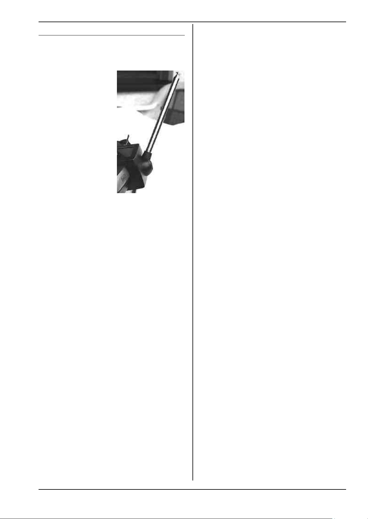
1. Set the transmitter
aerial in an upright,
slightly angled position
and then collapse all
the sections together.
2. Set up the model so
that the tip of the receiver aerial is about 1
m above the ground.
3. Ensure that there are
no large metallic objects (e.g. cars, wire
fences etc.) in the vicinity of the model.
4. Carry out the test only
if there are no other
transmitters switched
on - even if they are on
different channels.
5. Switch on the transmitter and receiving system. At
a range of about 80 m between transmitter and
model check that the control surfaces still respond
immediately and definitely to stick deflections,
without carrying out any unwanted movements.
When close to the range limit the servo output
arms will start to jitter; they should not move by
more than the width of the output arm.
6. Secure the model and repeat the test with the
power system running (alternating the throttle setting between idle and full-throttle).
The stated range of 80 m is only an approximate guideline, as the actual range will vary very greatly according
to ambient conditions. For example, effective range
may only be half the stated value at a mountain bowl
site, or close to a public radio transmitter, radar station
or similar.
What can you do to establish the cause of insufficient
range?
1. Change the position of the receiver aerial. If it is
close to metal parts or model components reinforced with carbon fibre, the receiver may suffer
adverse effects.
The influence of electric power systems and ignition systems also varies if you alter the position of
the aerial.
2. Disconnect the servos from the receiver one by one,
and repeat the check. Connecting leads of excessive length without suppressor filters have an adverse effect on reception conditions. Remember
that servos deteriorate with age, and then generate
more interference than when new (brush sparking,
suppressor capacitors adrift from motor terminals
etc.).
If you are unable to effect an improvement, try removing the complete system from the model and checking
the equipment on its own. This enables you to determine whether the fault is in the system, or in the installation conditions in the model.
Instructions
Pre-flight checks:
• Charge the transmitter, receiver and flight batteries
carefully, and check their state of charge before and
during the session. This means using the correct
type of charger, and a charge process which is suitable for the battery type in use. It also involves
regular care and maintenance of the packs (balancing by a slow charge), and testing the voltage curve
and capacity.
• At the flying site the first step should always be to
check with the other modellers present whether
your own channel (transmitter frequency) is vacant.
If there is a site manager or flight director present,
register with him and check that you understand
the method of frequency control in use. Do not
switch ON until you have done this, otherwise there
is a danger of channel clashes and wrecked models.
• Check the range with the transmitter aerial col-
lapsed.
• Ensure that you have selected the right model
memory.
• Check that all primary and secondary control sys-
tems are working perfectly, and that the control
surfaces are deflecting in the right “sense” (direction).
! If you detect any irregularity or problem, abort
the flight. Seek out the cause of the error, eliminate it, then check everything again.
When operating your model:
• If you have little or no experience flying radio-
controlled models, it makes sense to ask an experienced model pilot to help you initially. The use of a
Teacher/Pupil (Trainer) system is strongly recommended, especially for the initial phase of learning
to fly.
• Operate the model only at suitable approved sites.
• Never fly or run your model directly towards or over
spectators.
• Don’t carry out risky manoeuvres when flying or
operating your model.
• Have a clear idea of your abilities and skill; don’t
over-estimate what you can do!
• If you detect any sign of problems or interference,
land the model immediately and carry out a thorough check.
• Caution: static charges!
When the air is extremely dry (in mountainous terrain, in mountain bowls, close to weather fronts)
static charges tend to build up in the transmitter
and/or the pilot. The charge eventually dissipates
through a static spark, which can endanger the pilot or cause interference to the transmitter.
Counter-measures:
When you feel “static”, cease operations as soon as
you possibly can, and walk a little way down the
mountain to reach a less exposed position.
Page 61
Page 7

ROYAL evo
4. Liability / Compensation
As manufacturers, we at MULTIPLEX Modelltechnik
GmbH are not able to ensure that you observe these
instructions when assembling and installing this equipment. Neither are we in a position to influence the
way you install, operate and maintain the radio control
system components. For this reason MULTIPLEX Modelltechnik GmbH is obliged to deny all liability for loss,
damage or costs which are incurred due to the incorrect
use and operation of our products, or which are connected with such operation in any way.
Unless otherwise prescribed by law, the obligation of
MULTIPLEX Modelltechnik GmbH to pay compensation,
regardless of the legal argument employed, is limited to
the invoice value of that quantity of MULTIPLEX products which was immediately and directly involved in the
event which caused the damage. This does not apply if
MULTIPLEX Modelltechnik GmbH is found to be subject
to unlimited liability according to binding legal regulation on account of deliberate or gross negligence.
5. Guarantee
Our products are guaranteed in accordance with current statutory requirements.
If you wish to make a claim under guarantee please
contact the model shop who supplied the equipment to
you.
The guarantee does not cover malfunctions which are
due to the following:
- incompetent or incorrect usage,
- maintenance work carried out incorrectly, not
carried out at the correct time, not carried out at
all, or carried out by any non-authorised person or
organisation,
- incorrect connections,
- use with accessories not of genuine MULTIPLEX
manufacture,
- modifications or repairs which were not carried out
by MULTIPLEX or a MULTIPLEX Service Centre,
- use with components made by other manufacturers,
- accidental or deliberate damage,
- operating the equipment outside the limits stated
in the Specification.
6. Specification
No. of channels:
ROYALevo 9 9
ROYALevo 12 12
Transmission system: automatic adoption
to servo cpount
Servo 8 - 12 unused FM-PPM 7
Servo 9 - 12 unused FM-PPM 8
Servo 10 - 12 unused FM-PPM 9
ROYALevo 12 only!
at least one of the
servos 10 - 12 is used FM-PPM 12
Channel spacing: 10 kHz
Servo signal format: UNI 1,5 ± 0,5 ms
MPX 1,6 ± 0,55 ms
variable for each channel
Model memories:
ROYALevo 9 20
ROYALevo 12 36
Power supply: 7,2 V, 6 cells, AA size
NiMH-battery
Current drain: ~ 20 mA excl. RF module
~ 165 mA with HFM-4
~ 190 mA with HFM-S
Permissible operating
temperature range: − 15 °C to + 55 °C
Dimensions:
Length approx. 220 mm
approx. 250 mm with
aerial collapsed
Width approx. 200 mm
Height approx. 60 mm
excl. sticks and carry handle
Weight: approx. 750 g excl. battery
approx. 900 g incl. Battery
Page 62
Page 8
‰
ˆ
•
‡
†
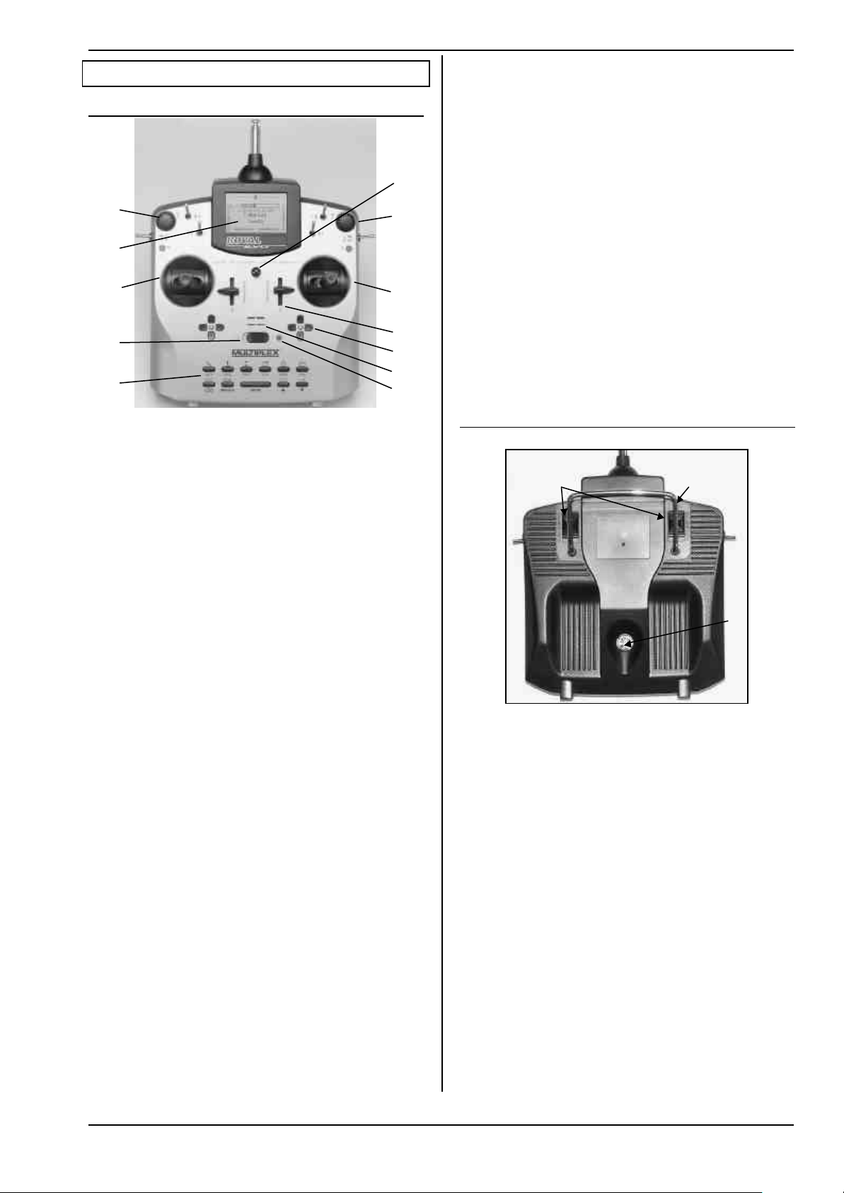
7. The transmitter
7.1. Front face of transmitter
Š
‰
•
‚
ƒ
„
…
•• Two precision stick units for controlling the 4 pri-
mary control axes. Stick ratchet for throttle/spoilers, can
be activated on right or left stick unit (è 7.4.6.). Both
units can be swivelled to suit the pilot’s personal preference (è7.4.7.). The stick tops can be rotated and are
infinitely variable in length. Various optional versions
are available.
‚‚ Two sliders “E” and “F” are fitted as standard, and
can be assigned to any channel. They also operate as
switched functions with centre detent.
ƒƒ Two cruciform trim assemblies located below the
stick units provide digital trimming facilities on the
primary control axes. Each set consists of a pair of buttons for left/right and up/down.
„„ Audible sounder (piezo beeper)
Instructions
All switches and buttons (apart from installation wells
“K” and “P”è 7.4.11.) are arranged as standard in easily
accessible positions. They cannot be re-positioned or
swapped over. The designations of the switches and
buttons are neutral (“G”, “H”, “I”, ... “O”, “P”). They can be
defined in any way to provide channel functions and/or
switched functions (transmitter controls or switches è
13.3.4. and 13.3.5.), i.e. the designations serve only to
identify them.
‰‰ The transmitter features two 3-D digi-adjustors
which are used for programming and adjusting the
system. They are a permanent feature and are fitted as
standard. During the programming process both digiadjustors can be pressed and/or rotated, and work in
parallel with the “ENTER” or „s“(UP) / „t“(DOWN) but-
tons. For operating a model it is possible to assign many
different parameters to the 3-D digi-adjustors, which
can then be used to adjust those settings conveniently
e.g. while the model is flying (è 10.2.2.).
ŠŠ Mounting lug for attaching a neckstrap
(e.g. # 8 5161 or # 8 5646)
7.2. Rear face of transmitter
•
‚
ƒ
…… When the transmitter is switched on, the RF status
display LED
Frequency) signal is being transmitted:
LED glowing constantly → no RF transmission
LED flashing (2 sec.) → RF transmission
The LED is controlled by the current drain of the RF
module. For example, if the transmitter crystal is not
present, or is defective, no RF signal can be generated,
and the constantly glowing LED alerts you to the fact
that an RF signal is not being transmitted.
†† Keypad consisting of 11 buttons in 2 rows. The 6
buttons in the first row provide fast, direct access to the
6 main menus (direct menu access buttons). The 5 buttons in the second row are used for programming procedures. With the exception of the “ENTER” button, all
the buttons have a double function for entering text.
The method of entering text is similar to that used with
mobile telephones.
‡‡ ON/OFF-switch („O“ / „1“)
ˆˆ The screen is a modern, UV-stable, graphical LCD
screen (132 x 64 dots) with an anti-reflective coating.
The contrast is variable (è 13.1.5.). The screen can be
moved through about 40º in order to optimise the viewing angle.
(red LED) indicates whether an RF (Radio
Two sliding latches • (OPEN) provide a fast, easy
method of opening and closing the transmitter, e.g. for
changing the crystal or RF module (è 7.4.3.).
The stout carry handle ‚ enables you to carry the
transmitter safely, and also protects the back of the case
when you put the transmitter down.
As usual with MPX, the ROYALevo features a MULTIPLEX
multi-function socket
case) as standard. Its purposes are as follows:
• Charging the transmitter battery (è8.4.)
• Connecting the transmitter to another for
Teacher/Pupil operations (è 13.4.)
• PC interface for backing up model data (è 19.6.)
• PC interface for updating the transmitter (è 19.6.)
• PC interface for flight simulators (è 19.6.2.)
• Interface for diagnosis lead, i.e. controlling a re-
ceiver for programming and adjustment without
transmitting an RF signal (è 19.3.2.)
ƒ (marked “CHARGE” on the
Page 63
Page 9
ROYAL evo
ƒ
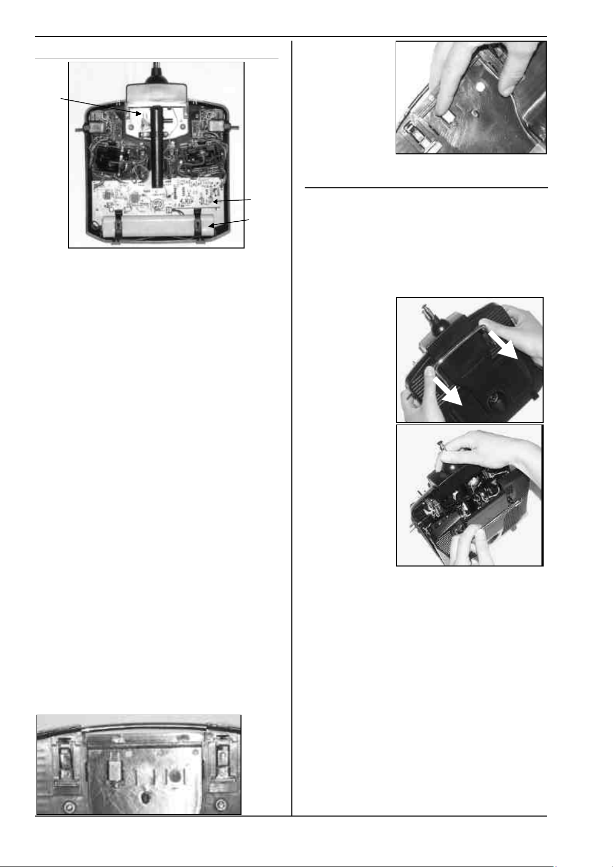
7.3. Inside the transmitter
Slide!
‚
•
The rechargeable transmitter battery • is installed as
standard. It consists of 6 environmentally friendly highcapacity AA-size NiMH cells (Nickel-Metal-Hydride). For
safety reasons the individual cells are spot-welded to
ensure constant contact, and the pack is protected by a
heat-shrink sleeve.
! The transmitter battery is fitted with a special
thermo-fuse which protects the battery and above all - the transmitter from short-circuit, reverse polarity and excessive currents. The transmitter itself does not feature a separate fuse, and
for this reason the battery may only be replaced
by a genuine MPX transmitter battery pack designed exclusively for this transmitter. It is also
very important to observe the instructions for
charging the transmitter battery (
RF module
ule is simply plugged into the main circuit board, and
can easily be changed if you wish to switch to a different frequency band (è 7.4.3.). Two different RF mo d-
ules can be used in the ROYALevo:
HFM-4:
A simple, low-cost RF module with plug-in crystals for
selecting the channel (transmission frequency). Use only
genuine MULTIPLEX transmitter crystals! The optional
“Channel-Check” power-on guard module can be fitted
at any time.
HFM-S:
A modern synthesizer RF module which allows you to
select the channel (i.e. transmission frequency) by software. An optional scanner with power-on guard can be
fitted at any time.
The TORX ® screwdriver ƒ (size T6), which you will find
in a clip below the aerial well, close to the screen, is
used for tasks such as swivelling the stick units, and for
installing the auxiliary switches in wells “K” and “P”.
On the inside of the transmitter back panel there are
crystal holders for 3 spare crystals.
‚ (Radio Frequency module). The RF mo d-
èè 8.).
! Don’t lever the crystals out! Slide them out!
7.4. Mechanical details
7.4.1. Opening and closing the transmitter case
! Be sure to switch the transmitter OFF before
opening it (short-circuit hazard)!
Opening the transmitter case:
1. Hold the transmitter in both hand s and push the
sliding latches on the back panel downwards with
your thumbs (towards “OPEN”) (Fig. 1).
Carefully lift off the back panel of the case (Fig. 2).
Fig. 1
Fig. 2
Closing the case:
1. Carefully position the back panel on the rear edge
of the case, holding it at an angle as shown, and
check that both retainer lugs are correctly engaged
(arrow) (Fig. 3).
2. Carefully close the case back (Fig. 4).
! Check that no cables are snagged, and that the
transmitter aerial has not slipped out of its guide
sleeve. It should be possible to fit the case back easily and without forcing.
3. Push the sliding latches up as far as they will go, in
the opposite direction to “OPEN”.
Page 64
Page 10
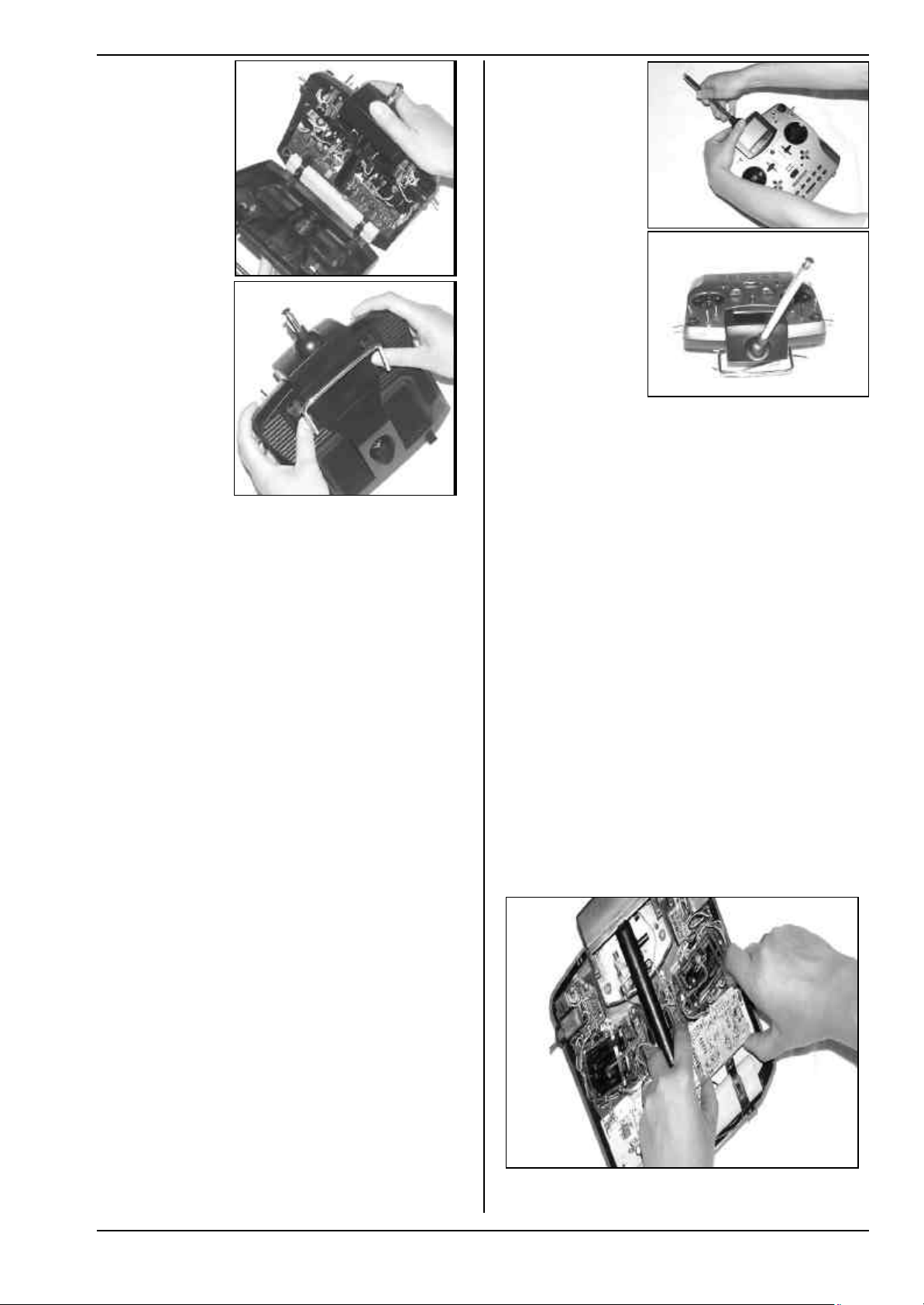
Fig. 3
Fig. 1
Instructions
Fig. 4
7.4.2. Adjusting the transmitter aerial,
fitting a new aerial
The transmitter aerial is a permanent fitting in the case.
For transport it can be collapsed completely and recessed into the case. For adjustments and programming
the aerial can be left in this position without damaging
the RF section.
! When operating a model always extend the ae-
rial to its full length. Only in this configuration
can you be sure of safe operation with maximum
radiated power and range.
The aerial can also be moved to a second position (angled up and to the left), and locked in that position:
1. Pull out the aerial until you feel a distinct resistance
(Fig. 1).
2. Pull the aerial another 3 to 5 mm to overcome the
resistance, pulling fairly hard, and swivel the aerial
up and to the left (Fig. 2). You will again feel resistance at this point, but this time do not push past it.
3. Tilt the aerial as far as it will go, and it will latch in
the correct position..
To swivel it back, the aerial must first be unlocked again
as described under point 2.
Fig. 2
7.4.3. Installing and removing the RF module
The two RF modules (HFM-4 and HFM-S) for the ROYALevo are not fitted in protective cases. To avoid damaging them:
• Don’t touch the circuit board and its components.
• Don’t exert any force on the circuit board.
• Protect RF modules from mechanical strain.
Don’t touch components on the circuit board.
!!
Don’t change the settings of adjustable components.
If settings have been changed mistakenly or components are damaged, have the module checked
an realigned by the MULTIPLEX service.
Removing the RF module:
1. Switch off the transmitter!
2. Open the transmitter (è 7.4.1.)
3. Lay the front face of the trans mitter on a soft surface, taking care to avoid damage to the sticks and
switches!
4. Grasp the RF module by all four corners using both
thumbs and index fingers, and carefully pull it up
and out (see picture below).
Replacing the RF module:
Grasp the RF module as before. Ensure that the module
is fitted onto the contact pins correctly, i.e. that it is not
offset in any direction.
! Check regularly that the aerial is still making
good contact. Contact problems with telescopic
aerials cause adverse effects on radiated power,
and thereby reduce effective range. In such situations reliable operation can no longer be guaranteed. Intermittent contact or bent aerials should
be replaced at the earliest opportunity, as should
an aerial that has become loose and sloppy
through hard use.
If the aerial should be damaged, it can be replaced easily as follows: Remove the case back, and simply push it
back and out of the aerial guide sleeve (replacement
ROYALevo aerial: # 89 3002).
! When changing the RF module avoid touching
Page 65
the electrical components at all costs. If the mod-
Page 11
ROYAL evo
(4) neutralising
force for right/left
stick moves
tick moves
neutralising
ratchet/friction
friction or ratchet
ule is to be stored outside the transmitter, it is
essential to protect it from dirt and damp, and also from shock and vibration.
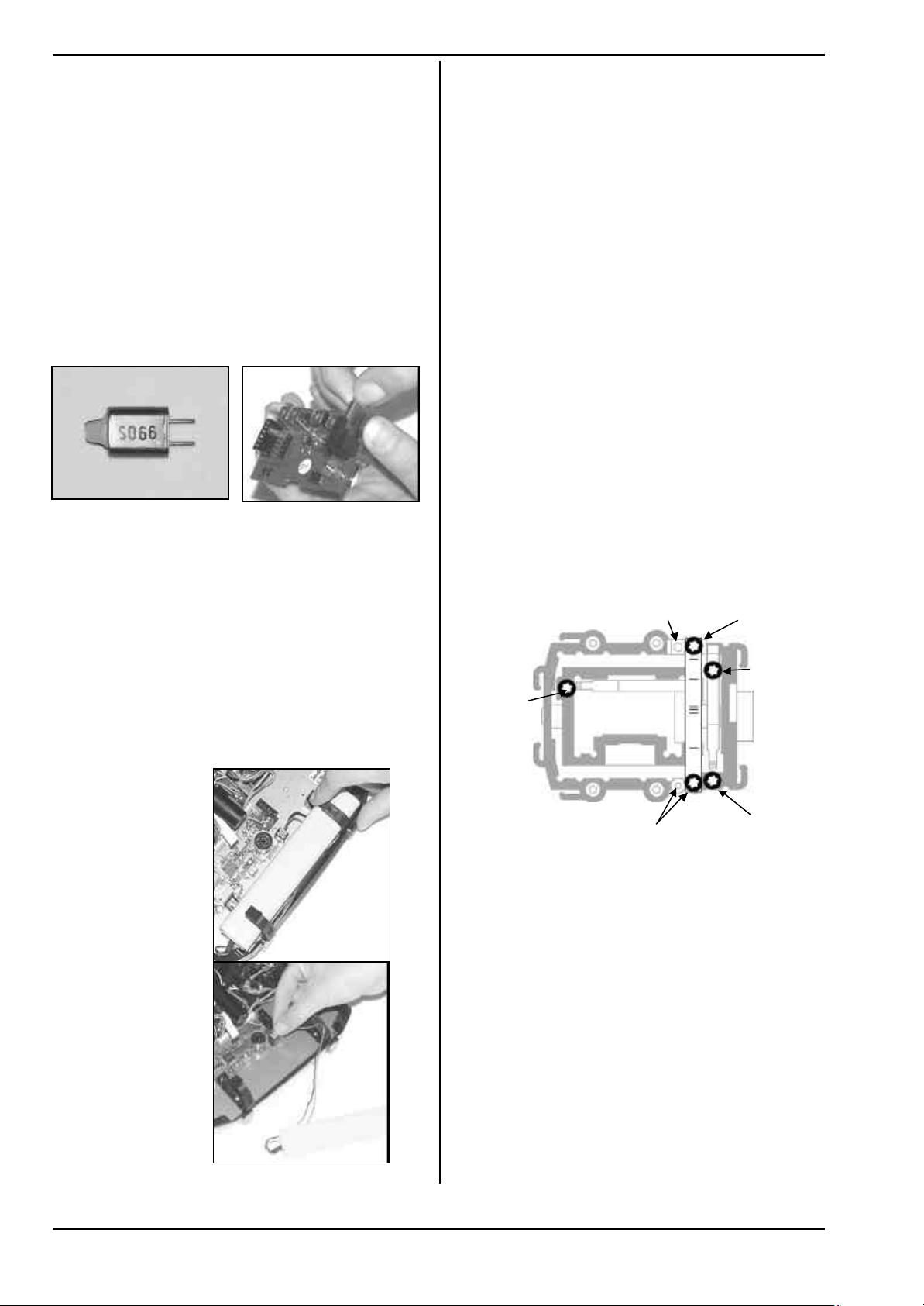
7.4.4. Changing the transmitter crystal
(HFM-4 module only)
The crystal should be pulled out of the RF module by its
plastic tag. First switch the transmitter OFF and remove
the RF module. When fitting a crystal ensure that it is
not mechanically stressed, and that the crystal pins are
not bent.
Use only MULTIPLEX transmitter crystals, designed for
the same frequency band as your RF module. We cannot guarantee reliable operation otherwise. MULTIPLEX
transmitter crystals are enclosed in a translucent blue
plastic sleeve and are printed with the code letters “S”
or “Tx”.
! Crystals are extremely delicate components,
vulnerable to shock and vibration. They are one
of the crucial parts of your RC system, without
which reliable operation is not possible. For this
reason never drop them, subject them to mechanical load (by pushing them forcibly into the
crystal socket), and always store them carefully.
7.4.5. Changing the transmitter battery
1. Switch the transmitter OFF!
2. Pull the snap-latches of the two plastic battery
holders back towards the battery, and fold them up
(Fig. 1).
3. Remove the battery and disconnect the battery
connector from the main circuit board (Fig. 2).
Fig 1
When installing the battery ensure that the battery lead
is correctly positioned, and cannot become jammed or
snagged when you close the case.
Note:
Model data is not lost when you change the battery.
7.4.6. Disabling the stick neutralisation system,
installing the spring for ratchet or friction operation
The ROYALevo transmitter is supplied as standard with
two self-neutralising stick units. The stick neutralising
system can be disabled, and a stick ratchet spring or
friction mechanism can be activated quickly and eas ily
as follows:
Switch off the transmitter!
1. Locate the TORX screwdriver (in a clip below the
aerial guide sleeve, close to the screen) and use it to
rotate the TORX screw (1) of the stick neutralising
arm clockwise until the neutralisation is completely
disabled. Don’t unscrew it too far! The neutralising
arm must not be removed!
2. If the stick shall work with friction the spring must
be displaced. Tighten screw (2) fully and adjust the
strength of friction/ratchet with screw (3). The further the screw is tightened, the greater the holding
force of the spring.
It is also possible to fit both springs if you wish. This
produces a hybrid ratchet / friction movement of the
stick which some pilots find they prefer.
(2) Spring position for
7.4.7. Adjust the neutralising force
The neutralising force is adjustable for each of the four
stick axis separately. The illustration above shows,
where the screws are located. Turning clockwise the
screws (4) increases the neutralising force.
(3) strength for
(1) disable
(4) neutralising
force for
forw./backw
s
Page 66
Fig. 2
Page 12
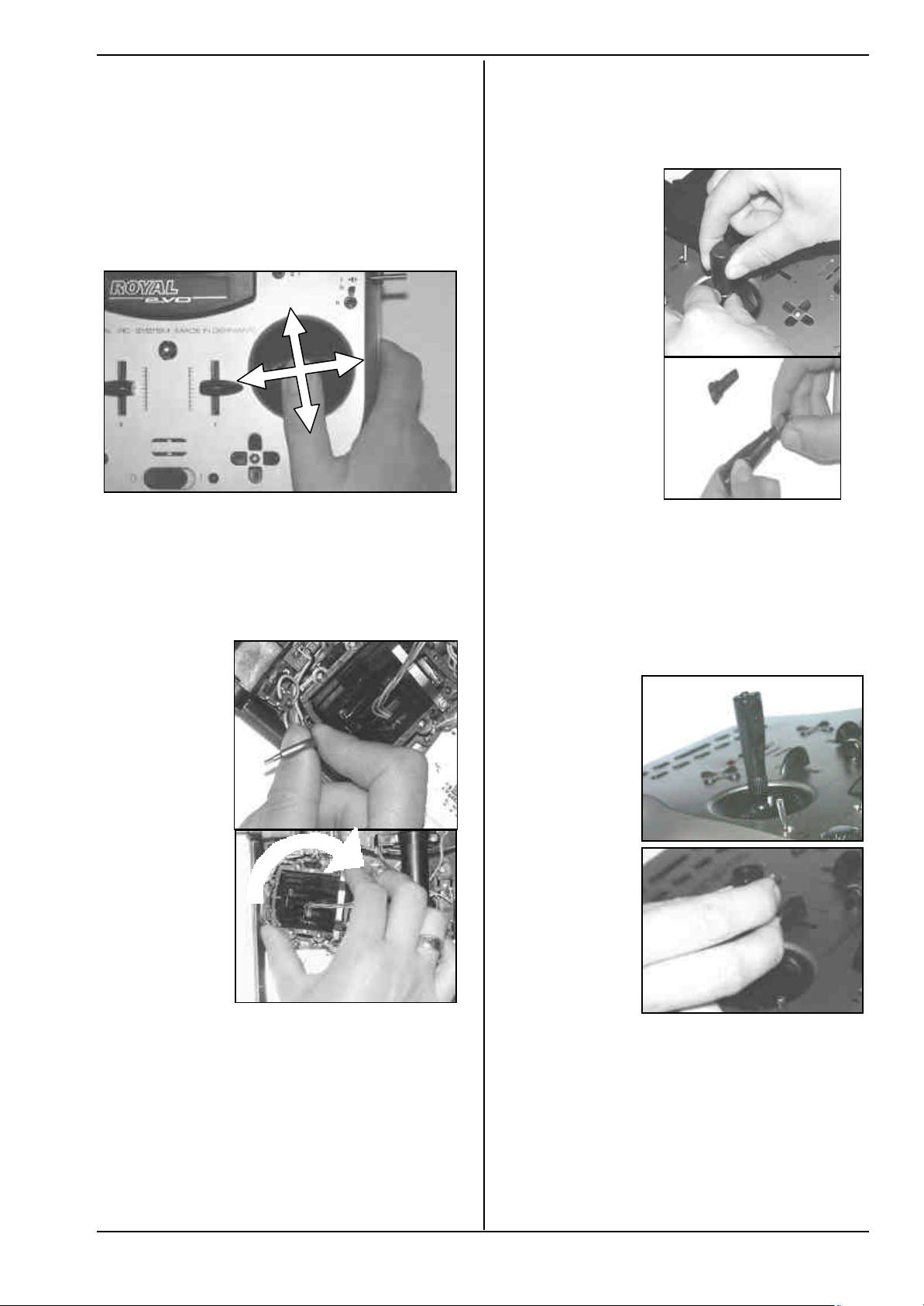
7.4.8. Swivelling the stick units
The stick units of the ROYALevo can be swivelled in their
mountings in order to align them perfectly with your
natural hand movements. This is a unique feature, and
can offer a real advantage when the transmitter is used
hand-held, with the thumbs operating the sticks, resting
on short stick-tops. In this hand position the “natural”
working action of the thumbs is at a slight angle to the
transmitter case, i.e. it does not coincide exactly with
the horizontal and vertical axes of the transmitter. Both
stick units of the ROYALevo are infinitely variable
through an angle of about 15°..
Instructions
nuts from the old ones, and use them to secure the new
stick tops (Fig. 2).
Before installing the stick tops ensure that the stick
shaft is clean and free of grease and oil. If you don’t do
this you may find that the stick top does not stay in
position reliably.
Fig. 1
1. Loosen the 3 TORX screws of the stick unit you wish
to swivel, using the TORX screwdriver (in a clip below the aerial guide sleeve, close to the screen) until the unit can be rotated (Fig. 1).
2. Swivel the stick unit to your choice of angle, then
tighten the screws again. Take care not to overtighten them, or you may strip the threads (Fig. 2).
Fig. 1
Fig. 2
7.4.10. Stick top with buttons -
how to fit them, how they work
If you use the transmitter with the long stick tops, you
will find that the long stick top with buttons (# 7 5303) is
very helpful, as it can be used for many important switched functions. This helps to ensure that auxiliary functions can be operated simply, quickly and safely,
without having to let go of the associated stick.
Fig. 1
Fig. 2
7.4.9. Adjusting and replacing the stick tops
As standard the ROYALevo is supplied with three pairs
of stick tops of different lengths. They are easy to
change, adjust in height, or rotate:
1. Place the transmitter on a flat surface.
2. Hold the stick top firmly in one hand (Fig. 1).
3. With the othe r hand undo the locking nut by rotat-
The top button has a non-latching or momentary function (e.g. pressed = ON, released = OFF), whereas the
two lateral buttons form one complete switch together
(e.g. button 1 = ON, button 2 = OFF). Fitting the stick
tops is a quick, simple procedure, and requires no soldering:
1. Switch off the transmitter and remove the stick top.
2. Thread the two wires attached to the new stick top
ing it clockwise (Fig. 1).
The stick shaft is smooth, and the stick top can now be
rotated or adjusted in length (position on the shaft). If
you are changing the stick tops, unscrew the locking
Page 67
Fig. 2
through the stick shaft (Fig. 1) and fit the stick top
again, as already described in Section 7.4.9.
Page 13
ROYAL evo
Tip:
Threading the wires is easier if you slightly bend the
wire-ends and hold the stick in one of the corners.
3. Clip the wires in the holders designed for them on
the stick unit. Check that the wires have sufficient
freedom when the stick is deflected; they must not
be under tension at any point, and should not snag
anywhere.
4. Connect the bare wire ends to the appropriate
green screw-terminals on the main circuit board;
you will need a small slot-head screwdriver for this.
Remove the battery and push the wires in from the
battery-facing side of the terminals. It does not
matter which way round the wires are connected.
Fig. 1
Fig. 1
Fig. 2
Fig. 3
Fig. 2
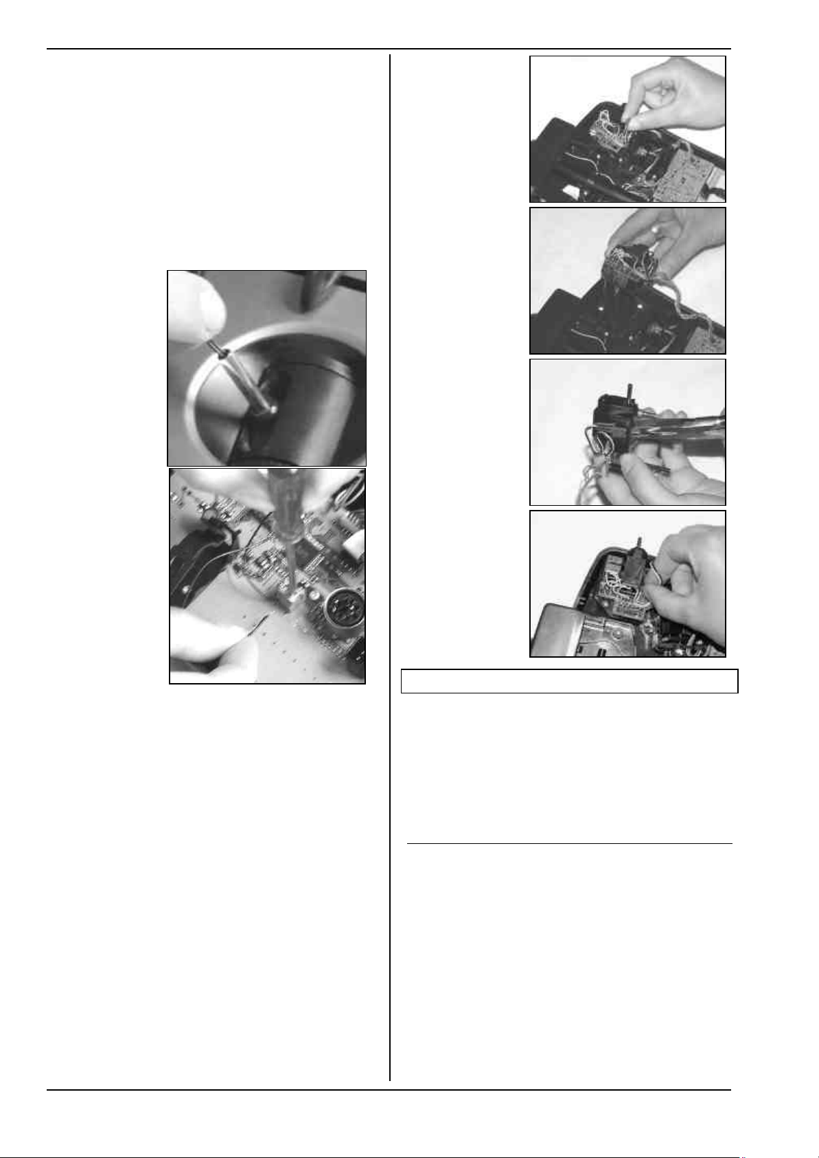
7.4.11. Installing the optional switches “P” and “K”
If you need extra functions 2-position switches can be
installed in the installation wells “P” and “K”. To fit them
the corresponding corner unit must be removed from
the transmitter:
1. Locate the TORX screwdriver (in a clip below the
aerial guide sleeve, close to the screen) and undo
the four TORX screws holding the appropriate stick
unit (Fig. 1).
2. Check that the switches are at the centre position,
then carefully withdraw the corner unit from the
transmitter. Remove the rotary knob (push-fit) from
the 3-D digi-adjustor when you withdraw the unit
(Fig. 2).
3. Use a small screwdriver to push out the blind cover
from the inside.
4. Fit the switch and secure it with the retaining nut
supplied (Fig. 3). Note the correct orientation: the
yellow wire should face the battery.
5. Re-install the corner unit, fit the retaining screws
and push the rotary knob back onto the 3-D digiadjustor (note correct position: internal index
shoulder). Connect the plug attached to the new
switch directly to the micro-connector on the corner unit (Fig. 4).
Fig. 4
8. The transmitter battery
The ROYALevo is powered by a high-quality ready-made
battery pack consisting of 6 NiMH cells (Nickel-MetalHydride) of the AA size. NiMH cells offer a much higher
energy density (capacity : weight) than NiCd (NickelCadmium) cells, and therefore provide longer operating
times for the same weight. They do require slightly different handling and greater care, especially when
charging.
8.1. Battery management in the ROYALevo
8.1.1. This is what we have already
Battery voltage display
Most transmitters show the battery voltage in graphic
or numeric form.
Battery alarm
An audible alarm indicates the voltage falling below the
minimum level. In many transmitters the minimum level
can be set by the user.
Both features are available in the ROYALevo of course.
(Battery alarm è 13.1.3.)
Page 68
Page 14
8.1.2. This is NEW
The battery management in the ROYALevo monitors
the charge status of the transmitter battery during all
operating conditions, even when the transmitter is
switched off.
In detail the following happens:
a. during charging
If the transmitter battery is charged with more
than 50 mA via the charging socket, the charging
current is measured regularly and the charge is calculated. The result is stored in the transmitters
memory..
b. during operation
Also during operation the current is measured and
the drawn charge is calculated and subtracted
from the available charge. In the status display 4
(è 9.6.) the remaining battery charge is shown.
Further the residual operating time is calculated
and displayed. This figure is shown to give a rough
idea of how long the transmitter can be operated
with the power consumption currently measured.
c. when the transmitter is switched off
Also if your transmitter „sleeps“ on the shelf, the
battery loses charge by the effect of self-discharge
(approx. 1.5% per day). The battery management
automatically reduces the available charge accordingly.
Battery charge an residual values are only intended
!!
as a guide. Tolerances and variations between individual examples, and the effects of battery maintenance schedules, can produce considerable discrepancies.
8.1.3. This is what you must attend
To get battery management display as reliable as possible, please take care of the following:
a. Correction of the indicated battery charge
The battery management assumes a nominal capacity of 1500 mAh. After the battery has reached
ist full capacity (more than 5 charge/discharge cycles) the true capacity can be set in the menu:
L , Transmitter parameter: Batt. charge
In steps of 50 mAh you can set the capacity measured by your charger.
If battery voltage of 6.5 V or below is de-
!!
tected, the available charge is set to 0 mAh.
b. Use a suitable charger (èè 8.4.) and charge via
the socket
Only if the battery is charged via the socket the
battery management can work correctly.
c. charging with constant current (1/10 C)
If the battery will be charged longer than calculated with the formula in chapter 8.4. the battery
management will limit the available charge at
1500 mAh.
Instructions
8.2. The essentials in brief
• 6 cells, 1500 mAh, NiMH (Nickel-Metal-Hydride)
• Integral thermo-fuse (automatic reset)
• Standard charge (0,1 C = 150 mA) 12 hours
• Fast charge (1 C =1,5 A) = maximum charge current
with automatic cut-off
• Avoid deep-discharging (< 1V/Zelle)
• during longer storage (more than 4 weeks) avoid
temperatures above 30°C
8.3. Safety notes
! The transmitter battery is responsible for supply-
ing power to the transmitter, and therefore
makes a vital contribution to the unit’s operational security
that you observe the following instructions on
charging and maintaining the battery.
. For this reason it is very important
! The transmitter battery is fitted with a thermo-fuse
with automatic reset which protects the battery
and transmitter from short-circuit, reverse polarity
and excessive current. The transmitter electronics
have no additional fuse! For this reason it is only
permissible
genuine MULTIPLEX transmitter pack!
to replace the battery with another
! Additional safety notes
• Batteries are potentially hazardous, and must be
stored out of the reach of children.
• Before each session check that the battery is in
perfect order. Damaged or defective batteries must
not be re-used.
• Never heat, burn, open or short out batteries. Do
not charge or discharge them at excessive currents,
overcharge or deep-discharge them, nor charge
them with reversed polarity.
• Place batteries on a heat-resistant, non-flammable
and non-conductive surface for charging, and do
not leave them on charge unsupervised.
• Do not make any modifications to the rechargeable
batteries. Never solder or weld direct to the cells.
• If these batteries are mistreated, there is a danger of
fire, explosion, burns and chemical burns. Suitable
extinguishing agents: water, CO2, sand.
• Escaped electrolyte is corrosive!
Do not allow it to contact your skin or eyes. In an
emergency wash the affected area with copious
amounts of water and seek the help of a doctor
immediately.
Page 69
Page 15

ROYAL evo
mArentCharge cur
8.4. Charging the transmitter battery
Never connect the TX without battery to a
!!
charger!
Chargers can supply high output voltages if no
battery is connected. This voltages can cause damages in the transmitter.
Charging with mains chargers or
!
12V-chargers for max. 8 cells
The battery can remain installed in the TX for
charging. Connection to the charger is made via
the charging socket on the back of the transmitter
(è 7.2.). Use only genuine MULTIPLEX charge
leads (e.g. transmitter charge lead with banana
plugs # 8 6020). For details of other charge leads
and battery chargers please refer to the current
MULTIPLEX main catalogue.
Charging with 12V-chargers
!!
for more than 8 cells
Never charge via the charging socket! Unplug the
battery from the electronics board and use the TX
battery direct charge lead # 8 6021.
The battery management can only work correctly
with a permanent connection (even if the transmitter is switched off) between battery and
electronics board to measure into (charging) or out
of (operation) the battery. Chargers for more than
8 cells need voltage converters producing high
voltages, which can damage the transmitter electronics.
Full capacity and performance
NiMH batteries only produce maximum performance
after a series of charge/discharge cycles (~5 cycles). The
first charge/discharge cycles should be carried out at
0.1CA (150 mA). Don’t fast-charge the pack until you
have done this.
What means C in charging advices?
C is the charging current, which supplies 100% of its
nominal capacity to a battery within 1 hour. This is a
current of 1500 mA for the 1500 mAh battey of the
ROYALevo. Charging with this current is named 1-C-
charging. This current can be derived from the nominal
capacity in mAh (or Ah) by just removing the letter “h”.
Standard charging
This means that the pack is charged at a current within
the range 0.05 to 0.2 C (75 mA to 300 mA).
The charge time is then calculated from the following
formula:
][
][
=
heCharge tim
Fast charging
This means that the pack is charged at a current within
the range 0.5 to 1 C (750 mA to 1.5 A). The charging is
finished by the automatic cut-off.
Timer-controlled charging is not permissible!
!!
Important with fast charging:
!!
The charger must be designed to cope with NiMH
batteries, i.e. Delta Peak termination sensitivity < 5
mV/cell, or temperature-controlled termination at
> 0.8°C/min.
Trickle charging
This means that the pack is charged at a current within
the range 0.03 CA to 0.05 CA (45 to 75 mA). Automatic
mAhCapacity
][
chargers generally switch over to this mode of charging
when the fast charge phase is concluded. After max. 20
hours trickle charging must be stopped.
This is the correct method of charging:
1. Switch off the transmitter
2. Switch on the battery charger designed for NiMH
batteries (see left column 8.4.) and connect the
charge leads.
3. Check polarity:
Red plug = positive terminal (+)
Blue/black plug = negative terminal (-)
Connecting the charger with reversed polarity
may ruin the battery!
(excessive heat, escape of corrosive electrolyte,
bursting of cells)
4. Connect the charge lead to the transmitter
5. Select the charge current (max. 1.5 A); alternatively
set the current after starting the charge process
Automatic fast chargers:
!!
Use manual current selection!
If the fast charger should interrupt the charge process prematurely, reduce the charge current and
start again.
6. If the battery becomes too hot during the charging
(touching impossible) immediately interrupt the
charging.
7. Disconnect the transmitter from the charger at the
end of the process.
8. When you have charged the battery enter the
charged-in energy in the menu L Transmitter,
Batt. charge (8.1.3. a.).
Note:
The development of rechargeable batteries continues
apace, just like other technical components. We therefore reserve the right to supply different battery packs
as standard in our transmitters, in order to keep the
equipment abreast of current standards.
8.5. Maintaining and storing
the transmitter battery
Always store NiMH batteries in the fully charged state.
This avoids the danger of deep-discharge.
Store NiMH batteries at a temperature between 0°C and
30°C, in dry conditions, and out of direct sunshine.
Charge unused NiMH batteries every 3 months. This
compensates for the natural self-discharge rate, and
again prevents deep-discharge.
If you have to store a battery for a long period, we recommend that you balance the cells by giving the pack
several charge/discharge cycles. Protracted storage may
reduce the pack’s usable capacity.
8.6. Recycling
Unlike NiCd cells, NiMH cells contain no cadmium,
which is a toxic heavy metal. Nevertheless, exhausted
cells should not just be thrown in the domestic rubbish.
Take the cells to your local specialist recycling centre.
The cells must first be discharged completely and made
safe against short-circuit (wrap in plastic film).
Page 70
Page 16
9. Using the transmitter
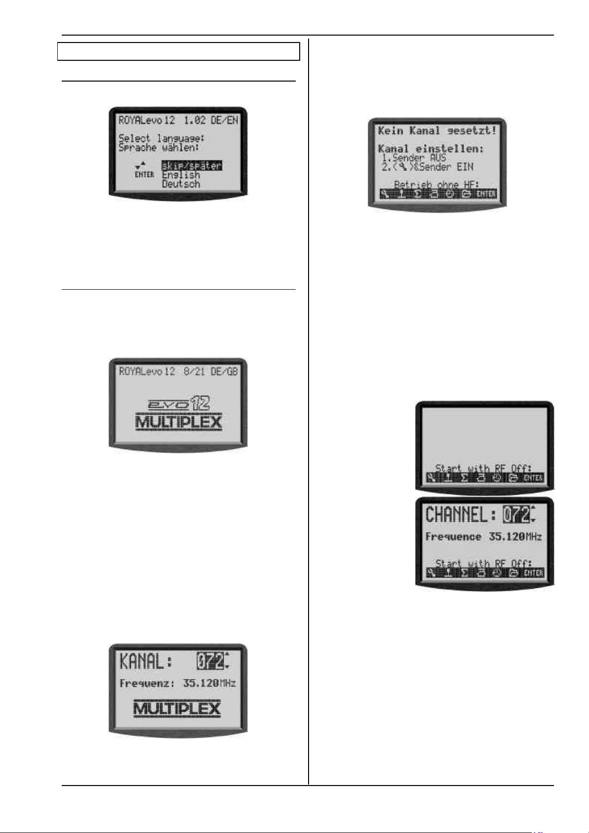
9.1. Switching on for the first time
When you switch on the transmitter for the first time
the following display appears:
Use the buttons „s“ (UP) or „t“ (DOWN) to select your
language and confirm by pressing „ENTER“. The lan-
guage can be changed at any time (è 13.5.2.). All userdefinable names (like mixer names, assignment table
names, model names) are not affected if you change the
language.
9.2. The power-ON procedure
When the you switch the transmitter ON, the following
power-on info screen will always appear briefly, regardless of whether an RF module is installed or not. This
gives information on the transmitter type, the current
software version and the languages available for the
screen texts:
Instructions
screen switches to the last active status display, and the
transmitter is ready to use.
The first time you switch the transmitter ON with a synthesizer RF module fitted, or after installing a different
synthesizer RF module, an information screen appears,
replacing the power-on info screen. This tells you how
to set the channel when using a synthesizer RF module:
The method of selecting a channel when using an HFMS synthesizer RF module is described in Section 9.4.
9.2.3. Switching on without transmitting an RF signal
Whether you are using an HFM-4 RF module for crystals
or an HFM-S synthesizer RF module it is possible to
switch the transmitter ON without transmitting an RF
signal, even when an RF module is installed. The transmitter can then be operated in that mode. This can be
useful for programming when no RF signal is required,
e.g. to minimise current drain, or when your channel is
already in use.
Hold the tool button L pressed in when you switch the
transmitter on ⇒ you are now at the power-on menu.
RF is OFF (⇒ LED glows constantly)
The following display appears:
If no RF module is fitted, the following message appears
briefly: „Note: No RF!“
9.2.1. Switching ON with the
HFM-4 RF module for crystals
After the power-on info screen (è 9.2.), the last used
status display appears (è 9.6.). If everything is in order,
the software immediately activates the RF module for
crystals, and an RF (Radio Frequency) signal is immediately transmitted. The LED starts to flash, the screen
switches to the last active status display, and the transmitter is ready to use.
9.2.2. Switching ON with the
HFM-S synthesizer RF module
After the power-on info screen (è 9.1.), the currently
set channel and transmission frequency appears briefly
for your information:
With
HFM-4 RF module
for crystals
With
HFM-S synthesizer
RF module
Pressing any direct menu access button, or the ENTER
button, takes you to the last active status display.
!! Note:
RF stays OFF until the transmitter is switched ON again.
After this the last used status display appears. If everything is in order, the software activates the synthesizer
RF module, and an RF (Radio Frequency) signal is immediately transmitted. The LED starts to flash, the
Page 71
Page 17
ROYAL evo
9.3. Security queries when switching ON
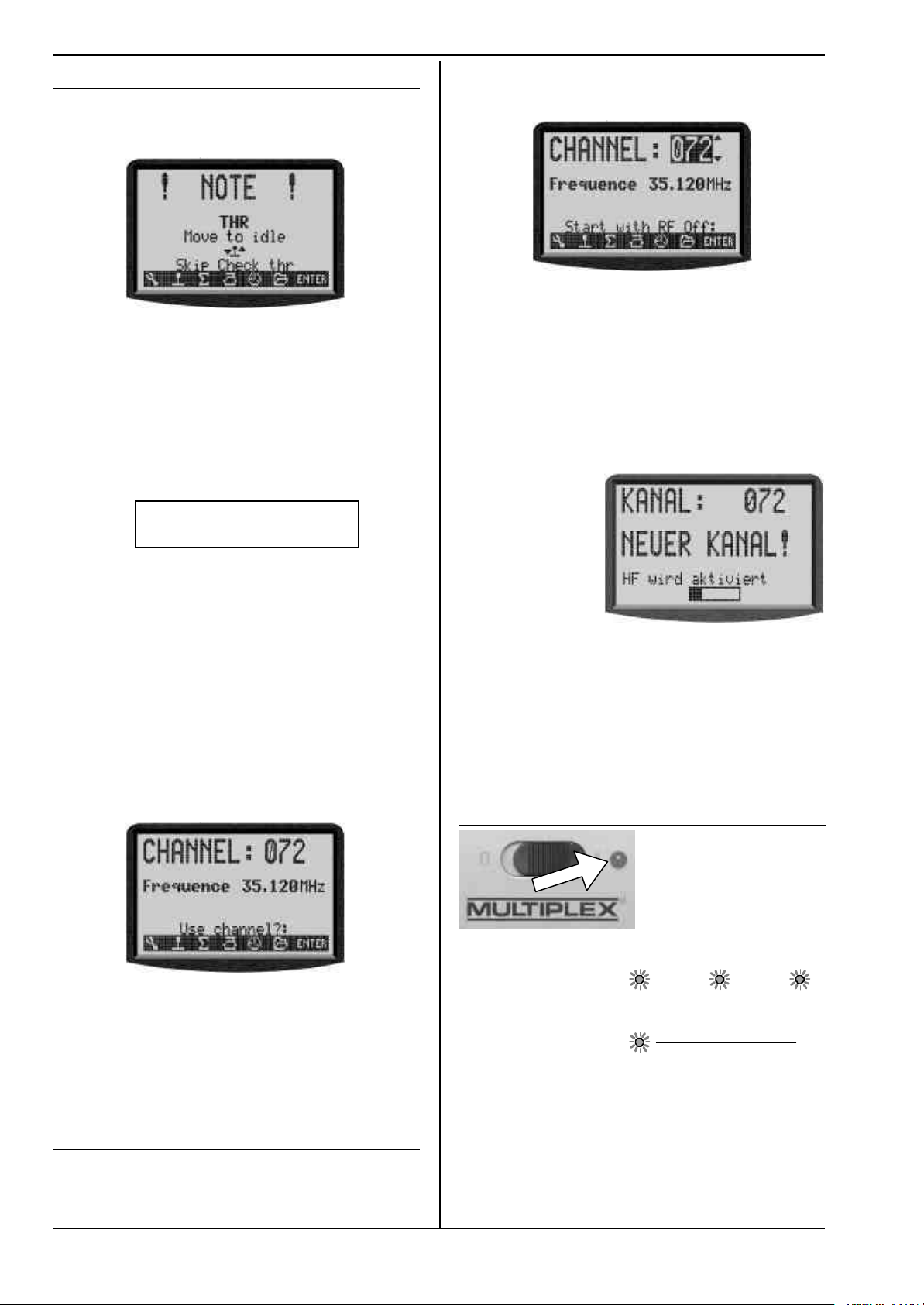
9.3.1. Throttle check
If in the menu L Transmitter the parameter Check
thr. is ON (è 13.1.6.), the following can appear:
The transmitter starts immediately and RF radiation
begins.
For safety reasons throttle is kept in idle until the
!!
throttle control (Heli: throttle limiter) is in idle position (Heli: at throttle minimum).
The symbol below the text reminds you of the
control, used for throttle. The figure above shows
the stick symbol.
If Throttle-Cut is active the transmitter immediately
starts operation and a message appears for 4 sec.:
ThrottleThrottle--Cut activeCut active
⇒ You are now at the channel setting menu,
RF is OFF (LED glows constantly).
The following display appears:
Set the channel you wish to use by pressing the „s“(UP)
/ „t“(DOWN) buttons, or one of the two 3-D digi-
adjustors. The channel is displayed as a channel number
and also the associated transmission frequency. To
activate the transmitter on the channel you have just
selected, the transmitter must now be switched OFF,
and then switched on again -.
2. Switch the transmitter OFF and then ON again
(this time WITHOUT the tool button pressed in)
You will see the following display::
English text:
Channel 72
H>
NEW CHANNEL!
Also in this case the corresponding switch is indicated.
The “Throttle Check” safety query can be switched ON
or OFF as required (è 13.1.6.).
' TIP ! If the safety query does not disappear
When missing or defective operating elements are assigned for Throttle and Throttle Cut the safety query can
be by-passed by pressing any of the menu buttons or
ENTER.
9.3.2. RF Check with the synthesizer module
If a synthesizer RF module is fitted in your ROYALevo, an
additional safety query can be activated (Check RF).
When you switch ON with an HFM-S synthesizer RF
module fitted, the following screen may appear after
the power-on info screen:
For safety reasons RF transmission remains OFF until
you confirm the displayed channel or transmission frequency by pressing any direct menu access button or
the ENTER button. Only then will you see the last active
status screen; RF transmission is then activated.
The “RF Check” safety query can be switched ON or OFF
as required (è 13.1.7.).
9.4. Selecting the channel with an HFM-S
synthesizer RF module
Channel selection with an HFM-S synthesizer RF module
is very simple, convenient and safe:
1. Switch on the transmitter with the tool button L
pressed in
Page 72
For your information the screen displays the previously
set channel. RF transmission remains OFF (=> LED glows
constantly) until the waiting period (horizontal bar on
screen) to activate the new channel has elapsed. During
this waiting period you have the chance to switch off
the transmitter before the RF module is activated, if, for
example, you have inadvertently set the wrong channel.
When the waiting period has elapsed, the last used
status display appears
The LED starts flashing, the transmitter is ready for use.
9.5. The RF status display (red LED)
an RF (Radio Frequency) signal is being transmitted or
not.
RF transmission ON: 2 sec 2 sec ...
The LED flashes at intervals of about 2 seconds and the
transmitter is ready for use.
RF transmission OFF:
The LED glows constantly.
The system monitors the current drain of the RF module
to check whether an RF signal is being transmitted or
not, rather than by checking the status of the RF module. If the current drain is below a typical value, either
no RF signal is being transmitted, or the RF signal is
being transmitted at less than full power (in which case
safe operation cannot be guaranteed!) This method of
Enable RF
The red LED (light emitting diode) constantly
indicates the current
status of the RF module
when the transmitter is
switched on, i.e. whether
Page 18
monitoring is much safer, as it is also capable of detecting faults and errors::
• Is an RF module installed?
• Is the connection between RF module and trans-
mitter in order (contact fault)?
• Is the RF module working correctly?
• Is a crystal fitted, and is it in order?
(only with HFM-4 RF module for crystals)?
• Is the transmitter aerial installed, and is it making
proper contact?
If the ROYALevo is in use as a Pupil transmitter, or in
diagnosis mode, no RF signal will be transmitted => LED
glows constantly.
9.6. The status displays
There are four different status displays available in total.
You can switch between the individual status displays at
any time (provided that you are at one of the other
status displays, i.e. not in a menu) using the „s“ or „t“
buttons, depending on the information you wish to see.
When you switch the transmitter on, the last used status
display will always appear.
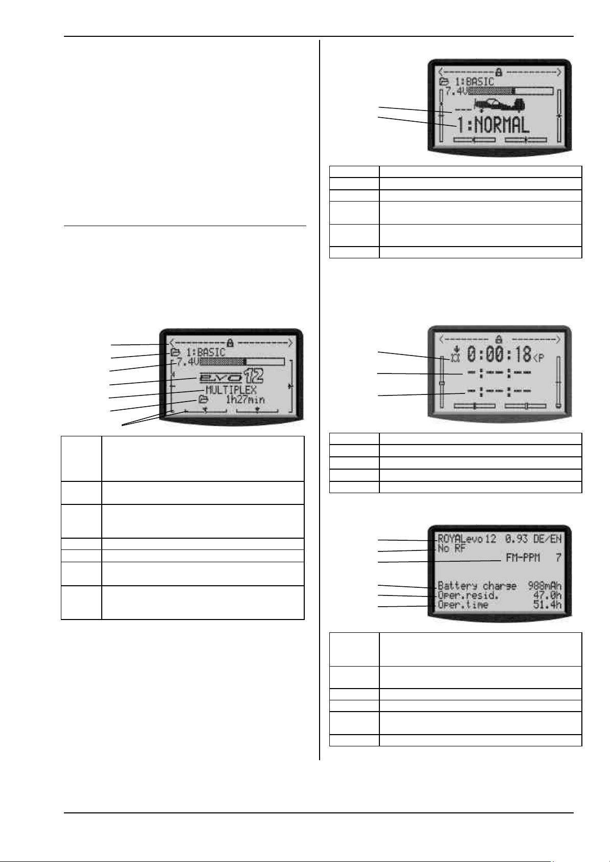
Status display 1
1
2
3
4
5
6
Bars
Line 1 Status of the 3-D digi-adjustors.
Numerous set-up parameters can be assigned
to the 3-D digi-adjustors, which can then be
varied directly (è 10.2.2.).
Line 2 Current model memory with
No. of the memory (1): model name(BASIC)
Line 3 Current operating voltage of the transmitter
battery in numeric form, and also graphically
in horizontal bar form
Line 4 Version: ROYALevo 9 or ROYALevo 12
Line 5
User name (è 13.5.3.)
Line 6 Operating time of the
current model memory(è 17.1.)
Bars The 4 bars at the sides and bottom of the
screen show the current trim positions of the
4 primary control functions/sticks (è11.4.)
Instructions
Status display 2 (flight phases)
1
2
3
4
5
Line 1 Status of the 3-D digi-adjustors, see above
Line 2 Current model memory, see above
Line 3 Current operating voltage, see above
Line 4 Code letter of the switch used to change
flight modes (è 18.4)
Line 5 Current flight mode with
No. (1): name (NORMAL)
Bars Current trim positions, see above
Status display 3 (Timers)
Only timers with assigned switches are displayed. Be-
hind the time the switch code letter is shown (P in the
example).
1
2
3
4
Line 1 Status of the 3-D digi-adjustors, see above
Line 2
Line 3
Line 4
Slot-Timer (è 17.2.)
Sum Timer (è 17.3.)
Interval Timer (è17.4.)
Bars Current trim positions, see above
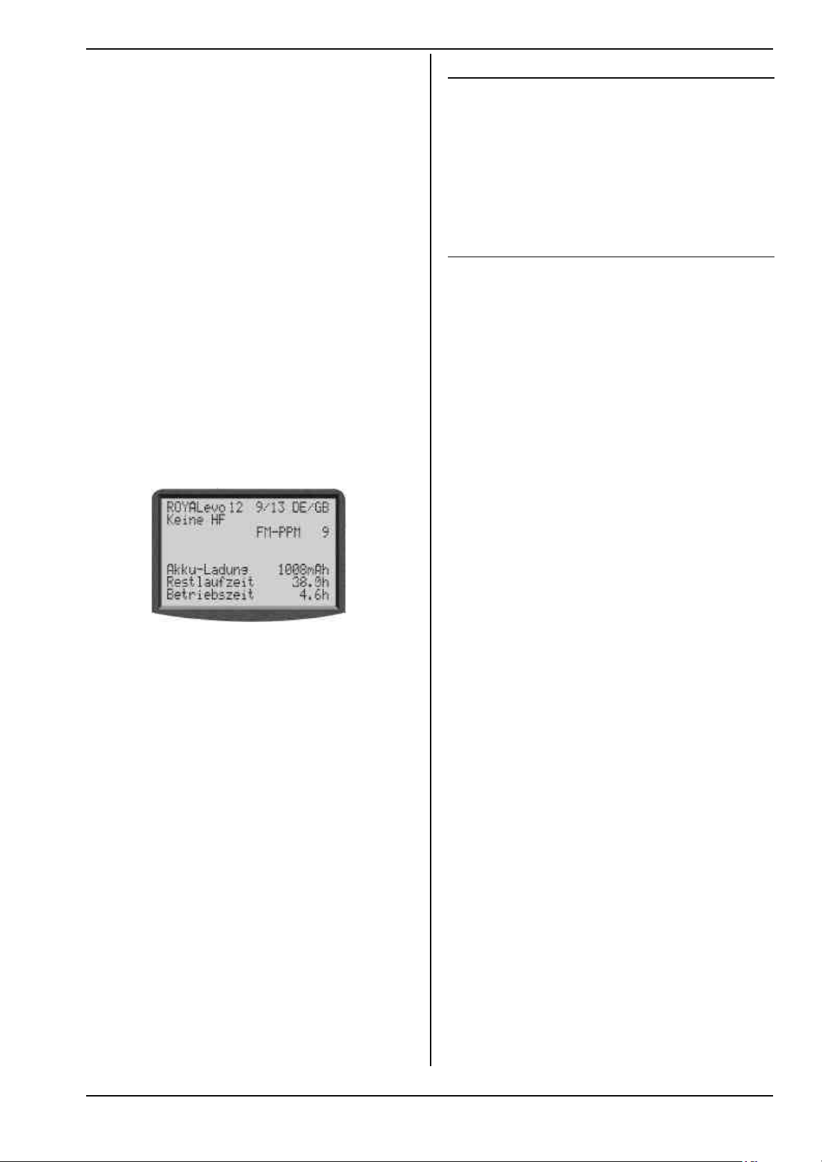
Status display 4 (system)
1
2
3
4
5
6
Line 1 Variant (ROYALevo 9 or 12),
software-version (e.g. 9/23),
language set currently loaded (e.g. DE/GB)
Line 2 with synthesizer module: channel no. freq.
else type of RF module (HFM-4) or "No RF"
Line 3 Transmission system (FM-PPM 9)
Line 4 available battery charge
Line 5 residual operating time with the residual
charge at the current power consumption
Line 6 Overall operating time of the transmitter
Page 73
Page 19

ROYAL evo
10. The basic operating philosophy
The ROYALevo features a new, very simple operating
philosophy which is easy and fast to learn. Proven elements of the operating systems used in our other renowned radio control systems are combined here. The
system is operated by means of a keypad, although one
or both 3-D digi-adjustors can be used optionally for
making adjustments and for navigating within the menus.
10.1. The keypad
10.1.1. Direct menu access buttons (row 1)
The keypad consisting of these buttons is used for programming or - more accurately - setting up the transmitter.
The 6 buttons in the top row are known as the direct
menu access buttons. When you press one of the buttons you move directly to the corresponding one of the
six main menus, all of which contain appropriate submenus. All these buttons are marked by a relevant symbol:
L
SETUP (configuration)
Button Function in the
status display
REV/CLR Reverse/clear button
ENTER Confirm button
No function
s t
10.1.3. Text input
For some programming procedures it is necessary to
input text. For example, this is required when entering a
model name (model memory), the user’s name, or the
name of a freely definable mixer. The text is entered
using the keypad (using the method commonly adopted with mobile telephones) and a 3-D digi-adjustor.
The keypad is used to select the letters and other symbols. The symbols which can be called up by pressing a
button rapidly and repeatedly are printed in small letters below each of the direct menu access buttons (row
1) and above the task buttons (row 2):
Manual reset or erase
timer times.
UP/DOWN button
Switch between status
displays
Cancel or reverse and
erase values and settings.
Select menus and
parameters/settings,
confirm and quit.
Select menus and
parameters/settings,
change values.
Function in
a menu
TRANSMITTER CONTROLS
H
MIXER
G
A
SERVO
TIMER
MEMORY
status display
Digi-assignment button
facility to change a
value assigned to one
of the two 3-D digiadjustors.
Function in
a menu
Selects a value which
can be varied using
one of the two 3-D
digi-adjustors.
K
I
10.1.2. Task buttons (row 2)
What we call the task buttons are required for a wide
variety of operations. The way they work varies according to what you are doing. The table below shows the
function.
Button Function in the
Opens or blocks the
If you enter a letter at the start of a text input process, or
after a space symbol, the software automatically renders it as a capital letter, and subsequent letters automatically as lower-case letters. If you wish to enter a
series of capitals, “leaf” through the lower-case letters,
and you will find the capital letters thereafter. When you
make a selection, the cursor moves automatically to the
next position. One of the two 3-D digi-adjustors can be
rotated to move the input cursor manually to any position, forward or back.
Press the “ENTER” button to end the text entry process.
You now see the following query:
“Clear rest of line? Yes -> (REV/CLR), No -> ENTER”
• Pressing the (REV/CLR) button erases all characters
following the last position of the cursor
• Pressing “ENTER” leaves the content unchanged.
Enter special characters
Some of the keys have hidden characters, not printed
on the transmitter case.
Button Character
ABC1
DEF2
GHI3
JKL4
MNO5
PQR6
STU7
VWX8
YZ_9
/-#0
Space
A B C 1 a b c
D E F 2 d e f
G H I 3 g h i
J K L 4 j k l
M N O 5 m n o
P Q R 6 p q r
S T U 7 s t u
V W X 8 v w x
Y Z 9 y z _
0 / ? ! - + % # & < > *
Page 74
Page 20

10.2. The 3-D digi-adjustors
The transmitter is fitted with two 3-D digi-adjustors as
standard, and these are used for programming and
setting up the system
10.2.1. Programming using the 3-D digi-adjustors
At the programming stage, both 3-D digi-adjustors
operate in parallel with the “ENTER” button when
pressed, and in parallel with the „s“ (UP) and „t“
(DOWN) buttons when rotated. You will soon find that
you naturally use one or other by default.
10.2.2. Making adjustments using the 3-D digiadjustors
It is possible to assign many different parameters to the
3-D digi-adjustors; you can then use them to adjust the
setting quickly and easily, e.g. when the model is flying.
One typical setting which can be adjusted and optimised in flight is aileron differential:
1. Select the aileron differential parameter (Fig. 1)
2. Press the < F > button
Instead of the parameter value the 3-D digi-adjustor
symbol (Fig. 2) appears. Now press one of the two
3-D digi-adjustors (in our example the right one) to
select it.
If you make a mistake, and the selected parameter
is not to be assigned, simply press the “ENTER” button.
Now you can quit the menu and go back to the status
display.
In the top line of status displays 1-3 you can now see
that aileron differential “Ail-Diff” is variable using the
right-hand 3-D digi-adjustor (Fig. 3). If you press or rotate the corresponding 3-D digi-adjustor for a moment,
the screen displays the current value of that parameter
(Fig. 4). A closed padlock indicates that the value cannot
be changed at the moment (as a guard against accidental operation).
If you want to be able to change the value, press the 3-D
digi-adjustor assignment switch <F>. The value can now
be changed. Every change you make is immediately
stored. Pressing the 3-D digi-adjustor assignment
switch once more blocks access to the value again
(symbol: closed padlock).
Bild 1 Bild 2
Bild 3 Bild 4
Instructions
Note: If you use flight phases
Setup parameters which have different values for each
flight phase are displayed correctly, i.e. the displayed
values vary according to the currently active flight
phase, and can be adjusted separately in each flight
phase using the appropriate 3-D digi-adjustor.
This is the procedure for erasing the assignment:
1. Hold the appropriate 3-D digi -adjustor pressed in
2. Press the REV/CLR button
⇒ the screen shows „- - -“ and the assignment is
erased
Alternatively you can “overwrite” an assignment at any
time by assigning a new parameter.
Which parameters can be assigned to a digi-adjustor?
The general rule is that only those parameters with
numeric values can be assigned in this way. However,
there are a few exceptions. In the following Display the
parameter Step (Step width for trim) can not be assigned.
Assignable parameters with numeric values are indicated by a high-set hyphen following the parameter
name. If you attempt to assign a parameter which cannot be assigned, a crossed-out 3-D digi-adjustor symbol
appears when you press the 3-D digi-adjustor assignment button.
ƒ
If you press a 3-D digi-adjustor in this situation you will
hear an audible error warning.
NOTE:
Assigned parameters can not be reversed unintentionally, i.e. modified “across 0” or OFF to values with the
inverted sign.
10.3. Working with the keypad and
3-D digi-adjustor -the fundamental
operating philosophy
These instructions have already described how to
switch the transmitter on, the type of status display, and
the information and method of operating the status
displays (è 9.1. / è 9.6.).
The following section explains the operating philosophy of the ROYALevo and the methods of working with
the keypad and 3-D digi-adjustors, using the example of
changing the screen language. The starting point is one
of the status displays 1-4 (è 9.6.).
10.3.1. Calling up main menus
To move to the transmitter’s menu level, the direct
menu access buttons are required (è 10.1.1.), and they
are also used for programming. Six main menus are
present in total, all of which contain appropriate submenus:
Page 75
Page 21

ROYAL evo
H
G
A
SETUP (configuration (è 13.)
Transmitter
Mixer definiitions
Assignment
Training
Userr
CONTROL (è 14.)
Access to the individual set-up menus for the
transmitter controls. The screen only displays
those controls which are used in the current
model (=> dynamic menu).
MIXER (è 15.)
Access to the individual mixer menus. The
screen only displays those mixers which are
used in the current model (=> dynamic menu).
SERVO (è 16.)
Calibrate
Assignment
Monitor
Test run
TIMER (è 17.)
Model/memory operating time
Slot timer
Sum timer
Interval timer
MEMORY (è 18.)
Select or change model
Copy model
Erase model
Flight phase management
Model properties
Create new model
To open a sub-menu press the “ENTER” button, or alternatively one of the two 3-D digi-adjustors.
The sub-menu opens.
To help you keep track of your movements, the first line
displays the symbol of the current main menu and the
name of the current sub-menu.
(Example language switch:
Main menu L Setup: sub-menu „ User “ )
Note:
If the area of the screen is not sufficient to list all the
sub-menus, you will see arrows „ © “ or „ ª “on the
left-hand edge of the screen. You can then “leaf
through” the list up or down using the UP/DOWN (s /
t) arrows, or alternatively one of the two 3-D digiadjustors, in order to reach the end or beginning of the
list. This is very similar to the process of “scrolling” in a
PC program. Example:
10.3.3. Changing values
Switching the display language is used as an example.
Starting from the status display you must proceed as
follows:
1. Press the L button
This opens the menu Setup. You can now select
the sub menu User using the UP/DOWN buttons
s t or alternatively one of the two 3-D digiadjustors. To move to the sub-menu press ENTER
(or).
2. Now select the parameter “Sprache” (German word
for language)with the UP/DOWN buttons s t (or
one of the 3-D digi adjustors).
L
K
I
Press the corresponding direct menu access button to
call up a main menu.
(Example, switch language: L button)
The following display appears:
The first line indicates the main menu in which you are
currently located (example main menu Setup: „L
Setup“).
The second line always shows „¨ Exit“.More on this:
(è 10.3.4.).
The following lines list the associated sub-menus. Four
dots .... after the name of the sub-menu indicate that
additional menus (sub-menus) are present.
10.3.2. Opening sub-menus
You can now select one of the sub-menus line by line
using the UP/DOWN buttons (s / t)*), or alternatively
one of the two 3-D digi-adjustors. The selected line is
always highlighted (displayed in inverse video). This
corresponds approximately to the cursor of a PC.
(Example: language switch: sub-menu „ User “ )
Page 76
Page 22

3. Press the ENTER button (or one of the 3-D digi
adjustors) to release the parameter for changing.
With the UP/DOWN buttons s t (or one of the 3D digi adjustors) you can now select one of the two
languages:
Your selection is confirmed by pressing ENTER (or
one of the 3-D digi adjustors) and you will leave
the parameter field.
Note on memorisation of modifications:
Modified values/settings are stored immediately in
the model memory. No manual storing procedure is
required.
' TIP !
Using the REV/CLR button
The value of a parameter can be changed using the
UP/DOWN (s t) buttons or one of the two 3-D digi-
adjustors, but in addition REV/CLR button can also be
used to reverse many values, or reset them to the default (standard) setting.
10.3.4. Returning from whence you came
When you quit the value/setting field the cursor moves
back to the last used parameter field.
To leave the sub-menus and main menus simply move
to the 2nd line „¨ Exit “ and then press the ENTER
(or one of the 3-D digi adjustors), until you return to the
status display.
Fig. 1 Fig. 2
Instructions
11. Digital trims
11.1. Introduction
The ROYALevo features modern digital trims for the 4
primary control axes (stick functions).
The trims of the ROYALevo operate on the “Centre Trim”
principle, i.e. trim corrections only affect the range around the centre of the stick travel, and not the endpoints. The advantage compared with conventional
trims is that the full control travel (and thus servo travel)
remains available, so you do not need to provide a reserve for trimming.
Top
end-point
Standard trim
The diagram shows what happens when the stick is
moved to the right: the servo moves to the top endpoint before the stick reaches its end-point. This means:
dead zone at one extreme of stick travel.
When the stick is moved to the left, the servo fails to
reach the bottom full travel point. That means: full servo
travel is not available.
Centre trim
Both servo end-points are always reached, regardless of
the trim position.
' TIP !
Since the response curve of the transmitter control is
altered when you adjust the “Centre Trim”, it is important that trim corrections should be relatively small. If
major corrections are required, always adjust the mechanical linkage!
11.2. Advantages of digital trims
Digital trims have two important advantages:
1. The trim buttons do not have a mechanical position
' TIP !
Direct switching to other main menus
If you are in one menu and wish to move straight to
another main menu, you can do this directly by pressing
the relevant direct menu access button.
' TIP !
Back to the status display
Pressing any direct menu access button twice takes you
quickly and directly to the status display you last used
(provided that you are not currently located at a parameter value).
Page 77
2. The ROYALevo features flight phases, and each
corresponding to the trim value (as is the case with
a conventional trim system with trim sliders). The
trim setting of the digital trim is displayed on the
screen, and the trim values are stored in the model
memory. If you change to a different model memory, the trim is immediately correct; you do not
have to move the trim slider to adjust the transmitter to the new model.
phase features its own trim memory for models used with flight phases. Each flight phase can easily
be trimmed accurately and independently of the
other phases.
Page 23

ROYAL evo
11.3. The cruciform digital trim assembly
The trims of the ROYALevo take the form of buttons
arranged in a cross, located below and to one side of
the stick units. They are located in an ergonomically
optimum position, and can be reached easily when the
transmitter is hand-held or installed in a tray.
ton (AUTO-REPEAT).
Each trim step (increment) is accompanied by a confirmation beep. When you reach the trim centre position,
and when you reach the ends of the available trim range, you will hear different sounds. You can switch the
trim beeps OFF if you prefer (è 13.1.2.).
Each press of a trim button
effects a trim adjustment
around the corresponding
control axis in the direction
of that button.
If you hold a trim button
pressed in for longer than
about 1 second, the trim
continues to increment
until you release the but-
12. Creating a new model
12.1. Basic information
With the ROYALevo you create a new model by selecting a model template. A total of eight model templates,
or sample models, are available, sub-divided into fixedwing and helicopters (detailed description of model
templates è 12.4.):
1. BASIC 7. HELImech
2. ACRO 8. HELIccpm
3. HOTLINER
4. DELTA
5. GLIDER
6. 4 FLAPS
The values defined by the template serve as starting
points, and have to be adjusted to suit your model. All
the settings and definitions can be altered at any time
and changed in any way you wish.
The trim of the 4th stick axis ( ‡‡) always works
!!
in idle trim mode for throttle!
This is also valid if SPOILER is assigned to this H
and for helicopters.
11.4. On-screen trim display
The trim settings are displayed on the screen in status
displays 1-3. They take the form of graphic displays in
bar form, on both sides and the bottom of the screen:
Starting from the trim centre position, a maximum of 20
trim steps are available in both directions. The trim increments can be set to any of 4 values from 0.5% to
3.5% ( TStep è 14.2.3).
!! Note: Trim step width, trim range
When you alter the trim step, the number of
steps stays the same. This means that both the
trim range and the actual trim value (!) are
changed, i.e. you must adjust the trims again if
you alter the trim increment size.
The current trim value is displayed on the screen in
graphic form, but it can also be displayed numerically if
you wish (parameter Trim è 14.2.2)
There are several variations in the form of the graphic
trim display shown in the status display (parameter
Trim graph è 13.1.1)
' TIP !
Reset trim to centre
If you press both buttons for one of the trimmed axis
simultaneously, trim is set to centre for the currently
active flight phase. This applies also to throttle.
" Take it in easy stages "
When you wish to create a new model with the
ROYALevo there are various ways you can proceed. In
our opinion the procedures described in the following
sections for fixed-wing models (è 12.2.) and helicop-
ters (è 12.3.) are the swiftest means of getting to your
destination.
12.2. A new fixed-wing model
Step ŒŒ Creating a new memory
New models are created by moving to the sub-menu
New Model in the I Memory menu (è18.6.).
This is the procedure once you have reached this menu:
1. The software automatically selects the first vacant
spot memory for the new model.
(Parameter Memory nr.)
2. You select a template to suit the model
(Parameter Template).
From the eight available model templates select
the one which is closest to your model (description
of model templates è 12.4.)
3. Choose the servo type and the servo assignment
(sequence) at the receiver.
(Parameter Servo conf.)
4. Select your preferred control mode (stick mode)
(Parameter Mode)
5. Select an assignment list (which transmitter controls operate the various functions).
(Parameter Assignment)
! Note re. assignment list
In each case you must use the stated assignment
list (from the three lists available) depending on
the model template you have selected. If you do
not do this, the model template cannot be guaran-
teed to function as described in the text (è 12.4.).
Page 78
Page 24

' TIP: Changing the assignment
If the default assignment of transmitter controls and
switches does not meet your requirements, you can
change the set-up at any time.
(è 13.3. L Setup, Assignment)
6. Leave the menu by selecting OK;
you have successfully created the new model.
Step •• Entering the model name
The model is assigned a name in the menu
I Memory/Properties (è 18.5.)
Instructions
Step ““ Pre-flight checks
Your newly created model is now ready to fly. Before
you operate the model for the first time be sure to test
all the working systems carefully.
You will probably need to fine-tune various aspects of
the control system, especially relating to mixers and
transmitter control settings, and this is done during the
test-flying process. Don’t be tempted to make changes
in a menu while the model is in the air. The safe, convenient method of altering values is to use the 3-D digiadjustor (è 10.2.2.).
Step ŽŽ Connecting servos
Connect the servos, speed controller, ... to the receiver,
keeping to the sequence of receiver outputs described
in the model template. The receiver output sequence
can be checked in the menu K Servo/Assignment
(è 16.2.).
! Note:
If you wish to connect devices (servos, speed controllers, ...) designed for different signal formats, you can
change this parameter separately for each channel in
the menu K Servo/Assignment (è 16.2.).
' TIP:
In the same menu you can also change the assignment
of the receiver outputs if necessary (in sequence and/or
function).
Step •• Switch on transmitter and receiver
! Note the correct sequence when switching on!
Always switch on the transmitter first,
and only then the receiver.
! Caution!
Injury hazard: power systems may burst into life!
In principle you can now control your model, but in fact
you need to set up the various values to suit the model
in question.
Step •• Calibrating the servos
Please work with the greatest care when calibrating.
Your model will only respond accurately to the controls
if the servos are correctly calibrated.
The servos are calibrated in the menu
K Servo, Calibrate (è 16.1.).
Step ‘‘ Setting up mixers
The mixers are set up in the menu G Mixer. This menu
is dynamic in nature, i.e. in the interests of clarity the
screen only displays the mixers used in the current model. The values assigned to the mixers in the model
templates are default (standard) values, and they will
need to be adjusted to suit your model.
Please refer to Section è 15 for all you need to know on
the subject of setting up mixers.
Step ’’ Setting up the transmitter controls
The transmitter controls are set up in the H Control.
Like the Mixer menu, this menu is dynamic in nature, i.e.
in the interests of clarity the screen only displays the
transmitter controls used for the current model.
è 14.
Step ”” Activating flight phases
Once you have test-flown the model in one flight phase
(usually the Normal flight phase) and successfully
trimmed it out, with all the mixer and transmitter control values set to your satisfaction, you can consider
setting up additional flight phases (if you wish). Flight
phases enable you to optimise the model for use in
different flight situations. The first step is to activate a
new flight phase and copy the values from the first
flight phase into the newly activated phase (è 18.4).
The transmitter control settings can now be adjusted (H
Control menu) to suit the new task. All the transmitter
control settings marked with a small number (1 …4) can
be adjusted separately for each flight phase (è 14).
12.3. A new helicopter
!! Safety note
Radio-controlled model helicopters are technically demanding flying machines which require fastidious setting up, maintenance and general care. If operated incompetently or irresponsibly they represent a serious
hazard.
If you are a beginner we recommend that you:
• Contact an experienced model pilot, your local
model club or a model flying school, and ask for
help.
• Ask your local model shop for advice.
• Increase your knowledge by reading all you can
find on the subject.
Step ŒŒ Creating a new memory
New models are created by moving to the sub-menu
New Model in the I Memory menu (è18.6.).
This is the procedure once you have reached this menu:
1. The software automatically selects the first vacant
spot memory for the new model.
(Parameter Memory nr.)
2. You select a template to suit the model
(Parameter Template).
From the two available model helicopter templates select the one which is closest to your
model: see table on the next page
Page 79
Page 25

ROYAL evo
Rotor head systems in tamplates
HELImech
Heliccpm
(Description of model helicopter templates è
12.11.)
3. Choose the servo type and the servo assignment
(sequence) at the receiver.
(Parameter Servo conf.)
4. Select your preferred control mode (stick mode)
(Parameter Mode è 13.3.1.)
5. Select an assignment list (which transmitter controls operate the various functions).
(Parameter Assignment è 13.3.2.)
Model with
mechanical rotor head mixing
Model with electronic rotor head
mixing (CCPM); at this stage the type
of swashplate (e.g. 3-point 120°, 3point 90°, 4-point 90°, ...) does not
matter. Setting up the appropriate
swashplate is carried out later.
By default the HELIccpm model template assumes a 3-point 120° swashplate with the “pitch-axis servo” arranged at the rear in flight direction.
! Note re. assignment list
In each case you must use the stated assignment
list (from the three lists available) depending on
the model template you have selected. If you do
not do this, the model template cannot be guaran-
teed to function as described in the text (è 12.4.).
' TIP: Changing the assignment
If the default assignment of transmitter controls and
switches (also the idle position, e.g. collective pitch
minimum forward or back) does not meet your requirements, you can change the set-up at any time.
(è 13.3 L Setup, Assignment)
6. Leave the menu by selecting OK;
you have successfully created the new model.
Step •• Entering the model name
The model is assigned a name in the menu
I Memory/Properties (è 18.5.)
Step ŽŽ Connect servos to the receiver
Connect the servos, speed controller, ... to the receiver,
keeping to the sequence of receiver outputs described
in the model template. The receiver output sequence
can be checked in the menu K Servo/Assignment
(è 16.2.).
!! Note: Models with CCPM swashplate
If you want to set up a model with electronic swashplate
mixing (CCPM), but it features a swashplate other than
the default arrangement in the HELIccpm template (3point 120°, pitch-axis servo at rear), you must first alter
the servo assignment in the menu K Servo, Assig nment (è 16.2). Please also read the notes relating to
Rotor head mixers (electronic swashplate mixer/CCPM
è 15.5.).
!! Note
If you wish to connect devices (servos, speed controllers, ...) designed for different signal formats, you can
change this parameter separately for each channel in
the menu K Servo/Assignment (è 16.2.).
Page 80
' TIP:
In the same menu you can also change the assignment
of the receiver outputs if necessary (in sequence and/or
function).
Step •• Switch on transmitter and receiver
! Note the correct sequence when switching on!
Always switch on the transmitter first,
and only then the receiver.
! Caution!
Injury hazard: power systems may burst into life!
In principle you can now control your model, but in fact
you need to set up the various values to suit the model
in question.
Step •• Calibrating the servos
Please work with the greatest care when calibrating.
Your model will only respond accurately to the controls
if the servos are correctly calibrated.
The servos are calibrated in the menu
K Servo, Calibrate (è 16.1.).
' TIP:
A 2-point servo calibration is sufficient for the throttle,
collective pitch and tail rotor servos. Before calibrating
the servos, remember to check that they rotate in the
correct direction; if you have to reverse a servo, you will
then need to re-calibrate it! For calibrating the two re ference points P1 and P5 use the Assign button, which
moves the servo to the correct position (and keeps it
there) regardless of the position of the associated
transmitter control (è 16.1.2). Adjust the percentage
values so that the servos move to the maximum travels
required, but do not strike their mechanical end-stops
(servo stalled) at either extreme of travel.
A 3-point servo calibration is required for the Roll and
Pitch-axis servos. Once again, do check that the servos
rotate in the correct direction before carrying out the
calibration; if you have to reverse a servo, you will then
need to re-calibrate it!
For the servos Head f/b, Head l, Head r and (if present)
Head 4 (CCPM swashplate) a more accurate calibration
can be carried out by using a 5-point servo calibration.
You can set the number of reference points in the menu
* Servo, Calibration(-> 16.1). Check that the servos are
working in the correct “sense” (direction) before you
start the calibration process; you can do this by moving
the collective pitch stick up and down. Use the assign
button for calibrating the individual reference points P1
... P5: all the rotor head servos will run to the appropriate position (and stay there) regardless of the position
of the associated transmitter controls. You can now
adjust the percentage values until the swashplate remains exactly horizontal at every reference point, without being mechanically obstructed (stalled) at the extreme points P1 and P5.
Step ‘‘ Setting up the rotor head mixer
(models with CCPM rotor head only)
The mixer is set up in the menu G Mixer, Rotor head (è
15.5.). The model template HELIccpm assumes the use
of a 3-point 120° swashplate with the “pitch-axis servo”
mounted at the rear, as seen from the tail. The values for
the parameters Geometry, Rotation and Lever are set in
Page 26

accordance with this default set-up. If your model features a different type of swashplate control system, you
will need to alter these values to suit.
The control travels can now be adjusted in the menu H
Control (è 14.2.4. Aileron Trvl, Pitch axis Trvl)
Step ’’ Setting up the collective pitch curve
The collective pitch curve is set up in the menu H Con-
trol Collect. (è 14.2.9.).
A separate collective pitch curve can be set for each
flight phase, so that the collective pitch control system
is an optimum match to each flight phase. For example:
• Hover
Collective pitch range -2 ... +10°: this means that the
model is less sensitive in response at collective
pitch minimum, making it easier to land the helicopter under full control.
• Acro
Collective pitch range -10 ... +10°: this means that
the model behaves the same in upright and inverted flight.
• Autorot
Collective pitch range -8 ... +12°: this means that the
optimum rotor blade settings for auto-rotation are
available at collective pitch minimum and maximum.
' TIP:
The blade pitch angle for hovering is usually in the
range approx. 4 ... 5°. When you are adjusting the collective pitch curves it is important to ensure that this value
is achieved at roughly the same position of the collective pitch stick on all the collective pitch curves you set
up, otherwise the model will “jump” when you switch
from one flight phase to another.
!! Note: Models with CCPM swashplate
The collective pitch curve points P1 and P6 should not
be set to + or - 100%, as this would mean that symmetrical cyclic control movements (pitch-axis or roll) would
not be possible at collective pitch maximum and collective pitch minimum. Depending on the set travels for
roll and pitch-axis we recommend a maximum setting
of approx. 75 ... 80% for P1 and P6.
Step ““ Setting up the throttle curve
The throttle curve is set up in the menu H Control,
Throttle (è 14.2.10).
The purpose of setting up a throttle curve is to obtain
constant system rotational speed over the full range of
collective pitch. Stable flight handling can only be
achieved if this is the case. Fine-tuning can only be carried out during actual test-flying.
!! Note
The throttle limiter must be at the full-throttle position,
and the direct throttle switch must be set to OFF. In this
situation the collective pitch -> throttle mixer is activated, and the throttle servo follows the movement of
the collective pitch stick in the ratio dictated by the
throttle curve you have set.
Instructions
Step ”” Setting up the tail rotor mixer
(static tail rotor compensation / REVO-MIX)
The tail rotor mixer is set up in the menu G Mixer, TAIL
(è 15.4).
In the model templates HELImech and HELIccpm tail
rotor compensation is switched off by default. If your
model is fitted with a modern gyro system which is
always operated in Heading Lock mode, you must set all
values for the TAIL mixer to OFF or 0%. An alternative is
to control the tail rotor directly using the Yaw function
instead of the TAIL mixer. To do this you need to change
the servo assignment (K menu, Servo/Assignment ->
16.2.) from TAIL to Yaw
If you are using a gyro system which is required to work
in normal or damping mode, the TAIL mixer should be
activated and set up carefully. This mixer prevents the
characteristic swing of the model around its vertical axis
when the torque level changes, and makes it easier for
the gyro to achieve optimum tail stabilisation.
This is the procedure for setting up tail rotor compensation:
1. Ensure that the servo output arm and the tail rotor
actuating arm are at right-angles to the tail rotor
pushrod when the tail rotor servo is at the neutral
position. If necessary adjust the length of the tail rotor pushrod until this is the case. An accurate mechanical adjustment in this way automatically defines a pre-set tail rotor setting which minimises the
helicopter’s tendency to swing when hovering.
' TIP:
If you fold both tail rotor blades to one side, the distance between the blade tips should be around 10 20 mm; the actual figure varies with the model.
2. Now move the collective pitch stick to the hover
position. You can now set the correct starting point
for the tail rotor compensation mixer by transferring the value of the Collective pitch parameter to
the Zero point parameter.
3. The level of tail rotor compensation for climb can
now be adjusted using the parameter Collective
pitch max. “Coll.+”.
Move the collective pitch stick to the Climb position
(collective pitch maximum), and set an initial value
which doubles the distance between the tail rotor
blade tips (when folded together as previously described). Now move the collective pitch stick to the
Descend position (collective pitch minimum) and
set an initial value which reduces the distance between the tail rotor blade tips almost to 0 (approx. 5
mm).
For the other flight phases (apart from Auto-rotation) it
is safe to start by adopting the same values. Fine adjustment of tail rotor compensation (Collective pitch+,
Collective pitch-) for the various flight phases can only
be carried out during flight-testing.
In the flight phase Autorotation (AUTOROT) tail rotor
compensation is not needed, as the motor is switched
off or at idle in this phase, and produces no torque
which requires compensation. For this phase set a value
of OFF for the parameters Collective pitch+ and Collective pitch-. Set the Offset parameter to a value which
sets the blade tips of the (folded) tail rotor blades in a
line (= blade pitch angle 0°).
Page 81
Page 27

ROYAL evo
Step •• Setting up and testing the gyro
The model templates are designed to reflect the fact
that most modellers nowadays use a standard gyro
system (normal/damping or heading lock) whose gain
(sensitivity) can be adjusted from the transmitter using
a separate channel.
In the ROYALevo’s two model templates HELImech and
HELIccpm the default setting is the simplest method of
gyro gain control: the gyro mode Transmitter control
(è 15.3). In this mode gyro gain is adjusted manually
using the transmitter control Gyro (slider E). If you wish
to assign a different transmitter control, this can be
done in the menu L Setup, Assignment (è 13.3).
The first step is to establish the position of the transmitter control which corresponds to maximum gyro gain.
This is done by moving the appropriate transmitter
control to one end-point, and moving the model around its vertical axis. At maximum gain the corrective
travel of the tail rotor will be at a maximum. If maximum
gyro gain is obtained at the opposite position of the
transmitter control, you need to reverse the “direction
of rotation” of the gyro channel (è 16.1.1).
The optimum gain setting for the gyro has to be established with the model in flight. For the first few flights
we recommend a gain setting of around 50%. During
the first few test-flights increase gyro gain gradually
until the tail begins to oscillate. Now reduce the gain to
the point where the oscillation can just no longer be
detected. This is the optimum gyro gain setting.
! Caution!
Before you fly the model it is essential to ensure that the
gyro is working correctly, i.e. that it is set up to counteract any rotational movement. If the gyro is set up incorrectly, it will amplify any tendency to swing, and the
helicopter will be uncontrollable. Please read the instructions supplied by the gyro manufacturer.
In addition to gain adjustment from the transmitter
control (gyro mode Transmitter control) the ROYALevo
offers further facilities for optimising gyro gain separately for each flight phase.
(gyro modes Damping, Heading è 15.3.).
now “released”, and the model is ready to fly. Throttle is
controlled by collective pitch via the throttle curve you
have already set.
Helicopter throttle curve
Programmed
throttle curve
max.
Collective pitch stick
Throttle limiter
+100%
+50%
0%
Throttle
Range blocked by
throttle limiter
min.
Actual course
of throttle
Direct Throttle
For testing and adjusting the motor the ROYALevo offers the Direct Throttle facility. Direct throttle means
that the motor can be controlled from idle to fullthrottle using the throttle limiter, independently of the
collective pitch stick. For example, the motor can be set
to full-throttle on the ground for testing, and can be
loaded with negative blade pitch (minimum collective
pitch) (keep a safe distance!). The Combi-Switch is used
to activate the Direct Throttle function (è 13.3.5.).
! Caution
Ensure that the throttle limiter is at idle before you activate Direct Throttle, otherwise the motor may run up to
full-throttle immediately!
Helicopter throttle
Throttle
+100%
Step –– Getting to know the method of working of
the throttle limiter and direct throttle
Throttle curve
Throttle limiter
We strongly recommend the use of the throttle limiter.
This is slider F in the model templates.
' TIP: Changing the assignment
If you wish to re-assign the throttle limiter (and also the
idle setting: idle forward/back) you can change it at any
time. (è 13.3. L Setup, Assignment)
When the throttle limiter is at the idle position, the motor runs at a rotational speed dictated by the parameter
Min. (è 14.2.10), For safety reasons the collective pitch
stick has no influence on throttle at this position. The
+50%
Trim
range
(20%)
0%
Idle
(Throttle min. + Trim)
Throttle min.
Note:
Use the Throttle-Cut to stop the motor not the throttle
trim. (è 13.3.5).
Throttle limiter
motor can now be started safely. Fine adjustment of the
motor’s idle speed is available at any time quickly and
simply using the trim associated with the collective
pitch stick. Set the model on the ground at the take-off
patch and move a safe distance away, then check that
the collective pitch stick is at collective pitch minimum
before slowly moving the throttle limiter to the fullthrottle position. The motor will now accelerate to the
throttle value corresponding to collective pitch mini-
mum (throttle curve P1 è 14.2.10.). The throttle curve is
Step —— Before test-flying
Your newly created model is now ready to fly. Before
you operate the model for the first time be sure to test
all the working systems carefully.
You will probably need to fine-tune various aspects of
the control system, especially relating to mixers and
transmitter control settings, and this is done during the
test-flying process. Don’t be tempted to make changes
in a menu while the model is in the air. The safe, con-
Page 82
Page 28

venient method of altering values is to use the 3-D digiadjustor (è 10.2.2).
Step ˜˜ Activating flight phases
Once you have test-flown the model in one flight phase
(usually the Hover flight phase) and successfully
trimmed it out, with all the mixer and transmitter control values set to your satisfaction, you can consider
setting up additional flight phases (if you wish). Flight
phases enable you to optimise the model for use in
different flight situations. The first step is to activate a
new flight phase and copy the values from the first
flight phase into the newly activated phase (è 18.4.).
The transmitter control settings can now be adjusted (H
Control menu) to suit the new task, especially the collective pitch curve and throttle curve. All the transmitter
control settings marked with a small number (1 ... 4) can
be adjusted separately for each flight phase (è 14.).
Step ™™ “Expert tips”
Mixer Thr.comp.Thr.comp. (Yaw/Roll/Pitch axisàà Throttle)
When the collective pitch, roll, pitch-axis or yaw commands are made, they may need a corresponding increase in the throttle setting. The mixer Throttle compensation (è 15.6.) is used for this.
Instructions
a. Check the stick functions (aileron/elevator/rudder); if
necessary select a different mode (è 13.3.1.)
L, Assignment, Mode
b. Check the direction of servo rotation for all functions,
if necessary reverse the directions (REVERSE)
K, Calibrate, select servo, Parameter REV/CLR
12.5. Template: BASIC
suitable for:
simple power models
models with one or two aileron servos,
models with spoilers (landing flaps or airbrakes)
Typical models:
Lupo, PiCO-CUB, Movie Star (fig. 12.4.2.), Twin-Star,
Big Lift
12.5.1. Assigned transmitter controls and switches
Assignment used: POWER
not used: Flap (F)
A : Sum timer ´ controlled by throttle (‡)
Dual-Rates Combi-Switch Throttle-cut
A/E/R (button)
OFF OFF
Mixture mixer
Some glow plug motors feature a carburettor with variable mixture facility, for which a separate servo is used
to maintain the optimum mixture at all throttle settings
(carburettor openings). One example of this is the WEBRA mc carburettor. The ROYALevo offers a special feature for this type of carburettor:
Assign the function Mixture to the receiver output to
which the mixture adjustment servo is to be connected,
and select 5P (è 16.2.3.) for the servo calibration. The
mixture can now be adjusted accurately in the menu K
Servo, Calibrate, Mixture (è 16.1.) , so that it suits all
positions of the throttle servo.
Mixture may not be assigned as control (è 13.3.4). If
you do so, Mixture will not be derived from the throttle
signal, but from the assigned throttle control. This
would be required if Mixture on an conventional carburettor is controlled by an auxiliary channel.
12.4. Model templates in detail
The following sections contain detailed descriptions of
all the model templates which are present in your
ROYALevo.
In each template description you will first learn the
types of model for which the template is suitable.
The first section (12.x.1.) tells you which transmitter
controls and switches are assigned. The drawing also
shows how the various switches and transmitter controls must be set to ensure that the model can be
switched on in as safe a state as possible.
The second section (12.x.2) includes a drawing showing
the receiver outputs to which the servos (speed controller, gyro) have to be connected. This sequence can be
changed in any way you wish (è 16.2.).
The third section contains (12.x.3.) notes on how to
adjust the model to meet your specific needs and preferences.
The next two steps must always be carried out
!!
when you start programming a new model.
Phase 1-3
1: NORMAL
12.5.2. Assigned servos / receiver outputs
To ensure that the template can be used for as many
model types as possible, more servos can be assigned
than are required for the model shown in the drawing.
4
1
Aileron
3
Rudder
ELEVATR+
12.5.3. Fine-tuning
Steps a. and b. (see left)
!!
c. Activate throttle - elevator mixer
select G, ELEVATR+, input Thr -Tr ,
set 10% down elevator
For fine adjustment in flight assign the value to the
3-D digi-adjustor (è 10.2.2.).
2
Throttle
Aileron
6
Spoiler
5
Page 83
Page 29

ROYAL evo
12.6. Template: ACRO
suitable for:
Power models such as F3A (formerly RC1), F3AX
Fun-fly models
Typical models:
Sky Cat (fig. 12.5.2.)
12.6.1. Assigned transmitter controls and switches
Assignment used: POWER
not used: Spoiler (E), Flap (F)
A : Sum timer ´ controlled by throttle (‡)
Dual-Rates Combi- Mix-1 Throttle-cut
A/E/R Switch Snap-Flap (button)
OFF OFF OFF
Phase 1-3
1: NORMAL
12.6.2. Assigned servos / receiver outputs
4
Throttle
1
AILERON+
12.7. Template: HOTLINER
suitable for: F5B
Typical models: Bonito, Akro, Akro Star
12.7.1. Assigned transmitter controls and switches
Assignment used: POWER
not used: Combi-Switch (N)
Spoiler (E), Flap (F)
A : Sum timer ´ controlled by throttle (‡)
Dual-Rates Combi- Throttle-cut
A/E/R Switch (button)
OFF OFF
Phase 1-3 Spoiler
1: NORMAL retracted
12.7.2. Assigned servos / receiver outputs
1
AILERON+
2
ELEVATR+
AILERON+
4
Throttle
5
5
23
Rudder ELEVATR+
12.6.3. Fine-tuning
(for ACRO)
Steps a. and b. (è 12.4.)
!!
c. Activate throttle - elevator mixer
select G, ELEVATR+, input Thr -Tr ,
set 10% down elevator
For fine adjustment in flight assign the value to the
3-D digi-adjustor (è 10.2.2.).
d. Activate flap - elevator mixer
select G, ELEVATR+, input Flap,
set Trvl' = 5%, Trvl# = 10%
For fine adjustment in flight assign the value to the
3-D digi-adjustor (è 10.2.2.).
AILERON+
12.7.3. Fine-tuning
Steps a. and b. (è 12.4.)
!!
c. Ailerons raised as landing aid
This function is already programmed in the template, and is controlled by the Spoiler transmitter
control (slider E). You may have to adjust the pitch
compensation ratio (15%) In the ELEVATR+ mixer.
d. Activate throttle - elevator mixer
select G, ELEVATR+, input Thr -Tr ,
set 10% down elevator
For fine adjustment in flight assign the value to the
3-D digi-adjustor (è 10.2.2.).
Page 84
Page 30

12.8. Template: DELTA
suitable for:
Deltas and flying wings powered or glider,
Model Jets
Typical models:
PiCOJet, TWIN-JET (fig. 12.7.2.), Stuntman
12.8.1. Assigned transmitter controls and switches
Assignment used POWER
not used: Combi-Switch (N)
Spoiler (E), Flap (F)
A : Sum timer ´ controlled by throttle (‡)
Dual-Rates Throttle-cut
A/E/R (button)
OFF
Phase 1-3
1: NORMAL
12.8.2. Assigned servos / receiver outputs
Instructions
12.9. Template: GLIDER
suitable for:
Gliders with two wing flaps (i.e. ailerons only), with
electric power, with V-tail
Typical models:
Flamingo, Kranich, Alpha 21/27
12.9.1. Assigned transmitter controls and switches
Assignment used: GLIDER+
not used: Flap (F)
A : Sum timer ´ controlled by throttle (E)
Dual-Rates Combi- Mix-1 Throttle-cut A/E/R Switch (ele-ail) (button)
OFF OFF OFF
Phase 1-3 Throttle
1: NORMAL Idle
12.9.2. Assigned servos / receiver outputs
Spoiler
1
AILERON+
6
Spoiler
7
4
Throttle
1
DELTA+
4
Throttle
12.8.3. Fine-tuning
Steps a. and b. (è 12.4.)
!!
c. Using a receiver with fewer than 5 channels
Change servo assignment: K Assignment
e.g. 1=DELTA+, 2=DELTA+, 3=Throttle
d. Control surface travels excessive or insufficient
select G mixer DELTA+,
change elevator and/or aileron inputs
e. Activate throttle - elevator mixer
select G, ELEVATR+, input Thr -Tr ,
set 10% down elevator
For fine adjustment in flight assign the value to the
3-D digi-adjustor (è 10.2.2.).
5
DELTA+
3
Rudder
If your model has an aero-tow release mechanism instead of a power system, you can use servo 4 to operate
it. The following steps are required:
1. Assign control
L, Assignment, Control, then select Tow rel.
and an element to operate it (e.g. button M)
2. Assign servo
K , Assignment, select servo 4, change Throttle
to Tow release
3. Adjust servo
Direction of servo rotation and end-points are set
under K, Calibrate.
12.9.3. Fine-tuning
Steps a. and b. (è 12.4.)
!!
c. Ailerons raised as landing aid ...
... if your model has no airbrakes
(servos 6/7).
Select G , AILERON+, set Spoiler input to 90%
Adjust the compensation ratio if necessary
in ELEVATR+..
d. Activate throttle - elevator mixer
select G, ELEVATR+, input Thr -Tr ,
set 10% down elevator
For fine adjustment in flight assign the value to the
3-D digi-adjustor (è 10.2.2.).
2
ELEVATR+
AILERON+
5
Page 85
Page 31

ROYAL evo
12.10. Template: 4-Flaps
suitable for:
F3B, F3J,
Glider with four wing flaps, with electric power,
with V-tail Typical models:
DG 600, ASW 27, Milan, EURO/ELEKTRO-MASTER,
Alpina (Bild 12.9.2.), ASH 26
12.10.1. Assigned transmitter controls and switches
Assignment used: SEGLER
A : Sum timer ´ controlled by throttle (E)
Dual-Rates Combi- Mix-1
A/E/R Switch (ele-ail))
OFF OFF OFF
Phase 1-3 Throttle Flap
1: NORMAL Idle neutral
12.10.2. Assigned servos / receiver outputs
12.11. Template: HELImech
suitable for:
Main rotor control systems with mechanical mixers
Typical models:
Ergo, Futura, Moskito, Raptor
12.11.1. Assigned transmitter controls and switches
Assignment used: HELI
A : Sum timer ´ controlled by THR.LIMITER (F)
Dual-Rates Direct Main Throttle
A/E/R Throttle phase Cut
OFF OFF OFF
Phase 1-3 Gyro Thr. limiter (Direct Thr.)
1: HOVER Centre Minimum
12.11.2. Assigned servos / receiver outputs
Spoiler
1
AILERON+
FLAP+
Rudder
4
Throttle
ç Aero-tow release instead of throttle: see 12.9.3.
12.10.3. Fine-tuning
Steps a. and b. (è 12.4.)
!!
c. Butterfly
This function is already programmed in the template, and is operated using the transmitter control
Spoiler (slider E). You may have to adjust the compensation ratio (15%) in the ELEVATOR+ mixer.
d. Activate throttle - elevator mixer
select G, ELEVATR+, input Thr -Tr ,
set 10% down elevator
For fine adjustment in flight assign the value to the
3-D digi-adjustor (è 10.2.2.).
6
3
8
2
ELEVATR+
Spoiler
9
7
FLAP+
5
AILERON+
12.11.3. Fine-tuning
a. Check stick functions (roll, pitch-axis, yaw)
Select different mode if necessary (è 13.3.1.)
L, Assignment, Mode
b. Check direction of servo rotation for all functions
If necessary change servo direction (REVERSE)
K, Calibrate, select servo, Parameter REV/CLR
c. Gyro features
è 15.3.
Page 86
Page 32

13.1.
13.2.
13.3.
13.4.
13.5.
12.12. Template: HELIccpm
suitable for:
Main rotor control systems with electronic mixers
CCPM (Cyclic-Collective-Pitch-Mixing)
with 3 or 4 servos, 90° to 150°
Typical models:
ECO 8, Logo, Fury, Three Dee NT, Uni-Expert
12.12.1. Assigned transmitter controls and switches
Assignment used: HELI
A : Sum timer ´ controlled by THR.LIMITER (F)
Dual-Rates Direct Main Throttle
A/E/R Throttle phase CUT
OFF OFF OFF
Phase 1-3 Gyro Thr. limiter (Direct Thr.)
1: HOVER Centre Minimum
12.12.2. Assigned servos / receiver outputs
The default setting in the HELIccpm model template is a
120° swashplate with the pitch-axis servo at the rear.
12.12.3. Fine-tuning
a. Check stick functions (roll, pitch-axis, yaw)
Select different mode if necessary (è 13.3.1.)
L, Assignment, Mode
b. Check direction of servo rotation for all functions
If necessary change servo direction (REVERSE)
K, Calibrate, select servo, Parameter REV/CLR
c. Gyro features
è 15.3.
Instructions
13. Main menu „Setup“ L
This main menu is primarily concerned with settings
which apply to the transmitter generally.
ü This symbol indicates global settings which influ-
ence the behaviour of the transmitter generally.
I Some settings apply only to the selected model.
These are marked with the model memory symbol.
13.1. Sub-menu „Transmitter“
13.1.1. Parameter „Trim graphics“
ü global effect
The current state of the trims can be displayed on
screen in any of 6 different ways (trim graphics 0 to 5).
We suggest that you try out the variants and set the one
which you find easiest to see at a glance.
13.1.2. Parameter „Sounds“
ü global effect
With this parameter you determine which events in the
transmitter trigger an audible signal.
Setting Audible signal
1.
Battery
2.
Batt+Time
3.
B+Ttim+Tr
4.
Init off
5.
All
13.1.3. Parameter „Battery alarm“
when battery voltage
falls below alarm threshold
as 1. + timer alarm
as 2. + trim adjustments
all, except during power on
always
ü global effect
Range 6,50 to 7,5 V (0,01V increments)
Default setting 6,9 V
The battery alarm is intended to alert you to a failing
battery, i.e. the charge is only sufficient for a limited
residual operating time.
! The lower you set the threshold, the shorter the
remaining residual operating time.
The residual operating time varies very widely according to the set threshold and the state of the battery. For
this reason it is important that you should carry out a
test to establish how much residual time is available in
your particular case.
This is done by switching on the transmitter with the
aerial fully extended, and the RF module with crystal (or
synthesizer) installed. You don’t need to move the
sticks. Set the alarm threshold to the desired value, and
leave status display 1 or 2 on the screen to show the
battery voltage.
Now time the period from the first audible alarm warning until the minimum operating voltage (6.5 V) is
reached).
! The transmitter switches itself off automatically
at around 6.3 V!
Page 87
Page 33

ROYAL evo
' TIP !
When you reach the alarm threshold that you prefer
(first audible alarm), set the threshold to 6.5 V. The
transmitter will then only emit an alarm when the battery falls to the minimum threshold. That tells you how
long you have to land your model. Don’t forget to set
“your” threshold again afterwards.
13.1.4. Parameter „Battery charge“
ü global effect
Is set to 0 mAh if the battery voltage drops below
6.5 V.
This parameter allows correction of the charge measured by the battery management system (è 8.1.).
13.1.5. Parameter „Contrast“
ü global effect
Range –8 to 8
Default setting 0
This parameter enables you to adjust the contrast of the
screen to suit the prevailing temperature conditions.
13.1.6. Parameter „ Check throttle “
I affects active model only
The ROYALevo provides 14 freely definable mixers. From
this “mixer pool”, which you create over a period of time
to suit your applications and models, you can use up to
5 different mixers in one model as often as you like.
Note for helicopter pilots
These freely definable mixers are only available
for fixed-wing models. The system provides a set
of ready-made mixers for model helicopters
which cannot be changed.
Note: Predefined mixers
Mixers 1-5 are already set up as standard, but they can
be changed at any time to suit your personal requirements. However, please note that we cannot guarantee
that the template will work 100% correctly if you change the standard mixers and subsequently create a new
model using a model template (è12.4.) which includes
the assigned “standard mixers”.
If you attempt to change one of these “standard mixers”
the following on-screen note appears:
! Guards against the power system starting up
accidentally when you switch on the model!
Check thr ONCheck thr ON
Electric-powered models may burst into life at full throttle when you switch on unless the throttle control on
the transmitter is at the idle position.
With Check THROTTLE = ON the software checks two
conditions when you switch on the transmitter:
1. Is Throttle -Cut switched off?
2. Is the THROTTLE control at idle?
The message is displayed as long as the throttle control
is not in idle positio n: RF radiation starts immediately,
but .due to safety reasons the throttle signal is kept in
idle.
13.1.7. Parameter “Check RF”
ü global effect
only possible with synthesizer RF module
! Safety query when transmitter is switched on!
Check RF ONCheck RF ON
Changing channels with synthesizer RF modules is relatively simple, so the ROYALevo provides an additional
security query which can be activated.
With Check RF = ON the transmitter asks you whether
you really want to start transmitting on the set channel;
this it does every time you switch on. You must confirm
this by pressing a button (or by switching the transmitter off again).
13.2. Sub-menu “Define mixer”
ü Defined mixers are globally available
13.2.1. How the freely definable mixers work
The basic principle of the ROYALevo’s freely definable
mixers is based on the proven method of working employed by the MULTIPLEX PROFI mc 3000 and 4000
series of radio control systems. A simple method of
explaining this is as follows:
We always start from the “control functions” or the servo movements. Example: aileron servo on a glider (predefined mixer: AILERON+). When do we want this servo
to move?
1. When the “aileron” control is operated
(primary function)
2. When the “spoiler” function is operated
(ailerons up as landing aid)
3. When the “flap” control is operated
(up/down movement of the ailerons to trim the
wing section for thermal or speed flying)
4. When the “elevator” control is operated
(up/down movement of the ailerons to amplify the
elevator response when flying “square” aerobatic
manoeuvres => snap-flap)
We can see that the aileron servo is to be controlled by
4 transmitter controls. The “AILERON+” mixer therefore
has 4 inputs (up to 5 inputs are possible).
The mixer adds together the value of the signals generated by the individual inputs (hence also the sum sym-
bol ££ ) and passes the result to the aileron servo or
servos.
If this or any other mixer is to work correctly on a model,
the following requirements must be satisfied:
• The appropriate assignment list with the correct
transmitter controls -> inputs must be assigned to
the model (è L Setup, Assignment, Controls).
Page 88
Page 34

FLAP+, ELEVATOR +
lieke AILERON+, FLAP+
(Spoiler in ELEVATOR+)
ter control.
• The mixer must be assigned to the appropriate
receiver outputs (è K Servo, Assignment).
• The inputs must be set up correctly, i.e. the magni-
tude and direction of the servo’s movements when
the input / transmitter control is operated
(è G Mixer).
1
5
Instructions
13.2.3. The mixer options
„Symmetrical“
™
Neutral position of control: Centre
one parameter: Travel
-100%
Servo travel
100%
100%
TrvTrv
Control
The control generates a
symmetrical movement
of the servo with variable travel around the
servo centre
Application sample:
travel
Input Aileron, Elev., Flap
in mixers like AILERON+,
' TIP:
For modellers familiar with the
PROFI mc 3000 and 4000:
The mixer inputs of the ROYALevo are now set at the
mixer, rather than at the servo end.
The advantage is this:
The inputs are set up at a single point (è 15.), rather
than at several points (servos). This makes the task of
setting up simpler and less time-consuming. It also
means that the setting of an input can be adjusted conveniently when the model is in flight, using a 3-D digiadjustor. Careful servo calibration (è 16.1.) is also im-
portant, otherwise you may find that multiple control
surfaces do not deflect by the same amount. This would
mean, for example, that a model being landed with the
ailerons deflected up would tend to turn to one side on
the final landing approach.
13.2.2. Defining mixers
Each mixer can be assigned its own name of your
choice. This is carried out in line 3 under Name
(è 10.1.3. text input).
The next step is to assign up to 5 mixer inputs (transmit-
ter controls) of your choice; this is done in lines 1 - 5.:
Col. 1 Mixer inputs (controls)
Aileron, elevator, rudder and throttle can be
assigned as required, with or without trim.
Example line 4: "Thr -Tr" = Throttle without trim
Col. 2
Col. 3 Mixer options (è 12.2.3.)
Page 89
Mixer switch Mix-1, Mix -2 or Mix-3
Can be used to switch the corresponding input
on or off.
"----" means that the input is always active.
How is the input to take effect?
Which settings are to be available when you set
up the mixer?
Where is the neutral position of the control?
š
Neutral position of control: Centre
two parameters: Travelñ and Travelò
œ
Neutral position of control: End-point
two parameters: Point1 and point2
›-
Neutral position of control: End-point
two parameters: Dead zone and travel
-100%
„Asymmetrical“
-100%
Servo travel
100%
-100%
100%
The transmitter control
generates an asymmetrical movement of the
servo around the servo
centre; travel can be set
differently for both
Control
travel
directions.
Application sample:
Input Flap in mixers
„Single-sided with curve“
-100%
Servo travel
100%
Pt1Pt1
-100%
Pt2Pt2
Control
100%
The transmitter control
generates a linear movement of the servo
from the servo centre,
with variable travel in
one direction.
travel
Application sample:
Non-linear inputs for
compensation
„Single-sided/linear with dead zone“
-100%
DeadDead
Servo travel
100%
-100%
TrvTrv
Control
100%
The transmitter control
generates a linear movement of the servo
from the servo centre,
with variable travel in
one direction and vari-
travel
able dead zone of the
transmit
Page 35

ROYAL evo
for AILERON inputs!
„Symmetrical with dead zone“
™-
Neutral position of control: Centre
two parameters: Dead zone and travel
Servo travel
100%
-100%
DeadDead
-100%
The option single sided/linear with offset is the only one
where the servo movement starts from the point defined by the OFFSET parameter and not from the centre.
„Single-sided, linear with offset“
›+
Neutral position of control: End-point
two parameters: Offset and travel
Servo travel
100%
Offs = 0%
-100%
OffsOffs
Offs = -50%
-100%
TrvTrv
100%
100%
Control
travel
TrvTrv
Control
travel
The control generates a
symmetrical movement
of the servo starting at a
point remote from the
control centre (dead
zone), with variable but
identical travel in both
directions.
Attention: Do not use
The offset moves the
end-pont of the servo
travel. Total travel of the
servo is Offs+Trv
Application sample:
Input Spoiler in the
mixer FLAP+ for large
travel down-wards with
butterfly (crow).
13.3. Sub-menu “Assignment”
The ROYALevo enables the user to assign the various
physical elements present (sticks, sliders, switches, buttons) as transmitter controls or switches (function switches)..
What are transmitter controls?
Transmitter controls are all those elements on your
transmitter which you can use to control a servo (speed
controller, etc.) on the model directly. In chapter 13.3.4.
you find a list of all possible controls for the ROYALevo.
What are switches?
What we term switches are physical controls which are
not used to control primary functions on the model.
They are used, for example, to switch mixer functions
(e.g. Combi-Switch), Dual Rates, timers and flight phases
on and off. In chapter 13.3.5. you find a list of all possible switches.
' TIP:
For modellers familiar with the MULTIPLEX PROFI mc
3000 and 4000:
All the control elements of the ROYALevo are permanently installed. The ROYALevo does not differentiate
“electrically” between transmitter controls and switches;
this means that any control element can be used as a
transmitter control and/or as a switch. It is no longer
necessary to assign what are known as “transmitter
control switches” or “Gx switches”. For example, if you
wish to time the motor run, simply assign the throttle
transmitter control as the timer switch.
Page 90
! Note: Predefined assignment lists
3 of the 5 assignment lists contain default assignment
data. This can be changed at any time to suit your own
requirements. However, please note that we cannot
guarantee that the template will work 100% correctly if
you change the standard mixers and subsequently create a new model using a model template (è12.1.)
which includes the assigned “standard mixers”.
Page 36

If you attempt to change one of these “standard mixers”
the following on-screen note appears:
Instructions
13.3.4. Parameter „Assignment - Controls“
Affects active assignment only (è13.3.2.)
13.3.1. Parameter „Mode“
I Affects active model only
The transmitter controls for the primary control axes
(sticks) aileron / elevator / rudder or roll-axis / pitch-axis
/ yaw are governed by the “Mode” (stick mode) parameter, rather than by assignment lists.
All 4 possible control modes are available. The arrows
are reminders for the assignment.
é stands for Rudder resp. Yaw
è stands for Elevator resp. Pitch Axis
Mode left right left right
1: è é
2: é è
3: è é
4: è é
The stick mode can be changed at any time (e.g. if another modeller accustomed to a different stick mode
wishes to fly your model). Changing the mode does not
affect any settings or values (e.g. trim settings) in any
way.
You can change the stick mode here in the menu L
Setup, Assignment (è 13.3.2.) as well as in the
menu I Memory, Properties (è 18.5.).
13.3.2. Parameter „Assignment“
I Affects active model only
You can change the stick mode here in the menu L
Setup, Assignment as well as in the menu I Mem-
ory, Properties (è18.5.).
13.3.3. Parameter „Assignment - Name“
affects only the active assignment
(è 13.3.2.)
Each assignment list (consisting of transmitter control
assignment and switch assignment) can be allotted its
own name. 8 characters are available (text input: è
10.1.3.).
Elevat.
Rudder
Rudder
Thr./Sp.
Elevat.
Aileron
Thr./Sp.
Aileron
Thr./Sp.
Aileron
Elevat.
Aileron
Thr./Sp.
Rudder
Elevat.
Rudder
Pitch
Yaw
Coll.
Yaw
Pitch
Roll
Coll.
Roll
Coll.
Roll
Pitch
Roll
Coll.
Yaw
Pitch
Yaw
The following control functions are available:
Control function Note
Throttle
Spoiler
Flap/RPM
L. gear
Tow hook
Brake
Gyro
Mixture
AUX1
AUX2
Collect.
Thr.limit
The corresponding transmitter control (control element) for the control functions listed above can be
assigned quickly and simply using Quick-Select.
Assigning using Quick-Select:
1. In Column 1 select the desired function (Column:
Control function)
2. Press ENTER to move to Column 2 (Column: Control
element)
3. Operate the desired control element
⇒ The screen displays the code letter for the control element you operated.
Flap for fixed wing models and
RPM control for helicopters
Auxiliary function/channel
Auxiliary function/channel
Helicopters only
Helicopters only
(throttle limiter/“Idle up“)
' TIP:
One control element can be assigned to multiple control functions, and can also be assigned simultaneously
as a switch (also for several functions).
1. Important!
Move the control element to the desired neutral
position (e.g. throttle to idle, spoiler to retracted
position, collective pitch to minimum position)
2. Press ENTER to confirm the input
⇒ cursor returns to column 1
If the control function is not required, erase the assignment by pressing REV/CLR ⇒ „ – – – “appears.
Column 3 shows the status ( * = ON, control element at
neutral position) and the direction of the neutral posi-
tion ( # / ' ).
Note: Assignment of push buttons
Please note the exceptions which apply when assigning
the following control elements: momentary switches
“H” and “M”, stick-top buttons “KTa” and “KSw” (è next
page).
Page 91
Page 37

ROYAL evo
13.3.5. Parameter „Assignment - Switches“
Affects active assignment only (è 13.3.2.)
The following switch functions are available:
Switch function Note
DR-ai
DR-el
DR-ru
CombiSwitch
Throttle-cut
µ slot
´ sum
¶¶ interval
Mix-1 ..3
Teacher
Main phase
Phases 1-3
Assigning a control element to one of the functions
listed above is carried out using Quick-Select, as when
assigning Transmitter controls (è 13.3.2.).
Dual-Rates for aileron or roll
(è 14.2.4.)
Dual-Rates for elevator or pitch axis
(è14.2.4.)
Dual-Rates for rudder or yaw
(è14.2.4.)
Fixed wing models:
ON/OFF switch for combi-switch
mixer (è15.1.)
Model helicopters:
Activates direct throttle
Activates Throttle-Cut function
Independent of the current throttle
setting the motor (electric or gaso-
line) is switched OFF (è 9.3.1.)
Activates slot timer
(è17.2.)
Activates sum timer
(è17.3.)
Activates interval timer
(è17.4.)
Fixed wing models:
Switches mixer inputs ON/OFF
(è 13.2.2.)
Model helicopters:
Mix-1: Switches gyro mode
Mix-2, Mix-3: no function
Transfer switch for teacher/pupil
(Trainer) operations (è 13.4.)
Aktivates primary flight phase 4
Aktivates secondary flight phases
' TIP ! Where is ON, where the OFF position?
The arrow (#/') behind the code letter in the menu
always points towards the ON position. Move the switch
to the position where you want the selected function to
be switched ON and confirm by pressing ENTER (or one
of the digi-adjustors).
The selected position is now memorised.
Exception: Momentary switches „H“ and „M“:
The momentary switches “H” and “M” are mounted on
the case sides; they feature two modes of operation:
1. Chage-over (toggle) „……“
Operate switch = function ON
Operate switch again = function OFF
Typical application: Timer
• Momentary „„„“
Operate switch = function ON
Switch not operated = function OFF
Typical application: Teacher/Pupil, Throttle-cut
Exception stick-top buttons:
The optional stick-top with push-buttons features a
total of three integral buttons:
• Top button KTaKTa
The assigned function is ON as long as the button is
pressed (momentary action)
• Pair of buttons on the side KSwKSw
One (selectable) button switches the function ON,
the other button switches the function OFF (toggle
action).
13.4. Sub-menu “Training”
13.4.1. Teacher/pupil operation
The ROYALevo „Teacher“ as well as „Pupil“.
In Teacher mode the ROYALevo can let the pupil control
up to 5 functions..
In Pupil mode 6 functions are supplied to the ou tput,
which can be accepted by a teacher transmitter.
13.4.2. The ROYALevo as Teacher transmitter
Connect teacher and pupil with the cable # 8 5121.
The following transmitters can be used as “pupil”:
ROYALevo, Cockpit MM, Commander mc, EUROPA mc,
PiCOline, PROFI mc 3010/3030/4000
Many older MULTIPLEX transmitters can also be used as
pupil transmitter. If your pupil transmitter is not mentioned above, please ask our after sales service.
1. Assign the teacher switch (è 13.3.5.). The assign-
ment also determines the switch position for
teacher enable.
2. Change to sub-menu Training.
Heli: Roll, Pitch axis, Yaw, Coll. Pitch, ---
(4 functions only)
"I>*" means, switch I on the right-hand side (>) of
the transmitter is assigned as teacher switch. The
asterisk behind indicates: The switch is currently in
ON position. Assignments using Quick-Select
(step 4.) can only be done if the switch is in this
position and the pupil can control the already assigned functions.
3. Select
Mode = Teach.M, if the pupil transmitter signal
output is in MULTIPLEX format.
Servo centre = 1,6 ms
Mode = Teach.U, , if the pupil transmitter signal
output is in UNIVERSAL format.
Servo centre = 1,5 ms
4. Select the function, which the pupil shall control
and press ENTER.
5. On the pupils transmitter quickly move the stick
axis (Quick-Select) to be used for the selected func-
Page 92
Page 38

tion. The corresponding channel number is displayed (e.g. K3 for aileron).
Check the movement directions for all control surfaces. Wrong directions can be reversed by pressing REV/CLR (# or ').
Attention: Quick-Select is not possible, if the
ROYALevo is switched on with “No RF”.
Repeat steps 4. and 5. until all desired channels are assigned. Now you can return to the status display and
start the training.
Be careful when assigning throttle if your engine
!
is running or the model is electrically powered!
Make sure not to endanger other modellers, spectators
or models by your engine bursting into life.
13.4.3. The ROYALevo as pupils transmitter
Important:
the trims are not operative (the teacher will trim the
model).
The following transmitters can be used as “Teacher”:
ROYALevo, Commander mc, PiCOline,
PROFI mc 3010/3030/4000
Some older MULTIPLEX transmitters can also be used as
teacher transmitter. If your teacher transmitter is not
mentioned above, please ask our after sales service.
1. Select the sub-menu training.
2. Select
Mode = Pupil U, if the teacher transmitter needs
NOTE:
If the ROYALevo is switc hed OFF without setting the
training mode to OFF, it will directly go to the Training
menu when you switch ON for the next time (safety).
If the ROYALevo works as pupils transmitter,
Mode = Pupil M, if the teacher transmitter needs
signals in MULTIPLEX format.
Servo centre = 1,6 ms
signals in UNIVERSAL format.
Servo centre = 1,5 ms
13.5. Sub-menu “User”
Instructions
If you enter the PIN correctly, the block is lifted. It is only
activated again when you next switch the transmitter
on.
13.5.2. Parameter „Language“
ü global effect
As standard the ROYALevo contains two language sets
for use in display texts. The default for the primary language is ENGLISH, and this is selected as active language.
The second default language is GERMAN.
In the menu L, USER you can invoke the LANGUAGE
parameter to select either of these two languages.
On the Internet (http://www.multiplex- rc.de/ you will
find a link to the page ROYALevo INFO. On this page we
will make alternative language sets available for you to
download. These files can be installed in the transmitter
using the ROYALevo PC program, and take their place as
the second language.
13.5.3. Parameter „Name“
ü global effect
If your transmitter is new, you will find the name MULTIPLEX in this field. You can enter your own name of up
to 16 characters. Your name then appears in status display 1 (è 9.2.).
14. Main menu „Controls“ H
By transmitter control we mean all the physical control
elements on the transmitter which are assigned to a
model function. These may include sticks, sliders and
switches. For instance, if you assign a switch for operating the tow-release, this constitutes a transmitter control. Which transmitter controls are present, and which
elements are to be used to operate them, is determined
in the menu L -Assignment, Controls.
The Assignment Controls menu is dynamic, i.e. it displays only those controls which are used in the active
model. If you are operating a simple model which only
features rudder and elevator controls, the menu will
look like this:
13.5.1. Parameter „PIN“
ü global effect
The PIN can be used to protect the settings stored in
your transmitter. If the PIN is activated, the operator can
view the set values, but not change them.
PIN=0000
If you enter this PIN, the values in the transmitter are
not protected against changes.
PIN = **** (four digits)
The PIN must contain at least one digit which
is not „0“!
If you enter a PIN, the lock takes effect next time you
switch the transmitter on. You can leaf through all the
menus, but as soon as you attempt to change a setting,
the following message appears:
Page 93
Section 14.2. informs you first which programmable
characteristics (parameters) are possible for the individual transmitter controls. Paragraphs 14.2.1. to 14.2.10.
describe the individual parameters in detail.
14.1. Sub-menu „Control switch“
I Affects active model only
Range -100% to 100%
Default 0% (control centre)
always appears at the end of the controls list
Page 39

ROYAL evo
Transmitter control switches are used when you wish to
trigger a switched process using a proportional transmitter control.
Example: motor run, electric motor
You wish the sum timer to start running as soon as the
throttle is moved past the 1/4-throttle point.
To achieve this you must assign the same transmitter
control to act as the sum timer switch as the one you
use to control the motor.
If you use an analogue control such as a stick as a switch
(or control E or F) the switching point can be defined at
any point you wish.
14.2. Sub-menus for individual controls
Aileron
Elevator
Rudder
Coll. pitch
Throttle
RPM
Thr. limiter
Retract
Trim 4x
Step
D/R
Trvl 4x
Expo
6-pointColl.curve4x
Min.
5-pointThr.-curve
4x
Run time
Fixed val.4x
– No adjustments
run time 0.0 to 4.0 sec
display only
0.5/2.5/2.5/3.5%
0% to 100%
0% to 100%
-100% to +100%
Collective: -100% to +100%
Thr-Minimum 0% to 100%
Throttle: 0% to 100%
0.0 to 4.0 sec
OFF, -100% to +100%
Tow hook
Brake
– No adjustments
Gyro
AUX 1
AUX 2
– No adjustments
14.2.1. Control settings for the primary axes
Transmitter controls for fixed-wing models
This menu only displays those transmitter controls
which are used in the active model. This means that
they are either assigned directly to a servo, or are used
in one of the mixers you have set up. We term this a
“dynamic menu”.
The menu point Transmitter control switch (è 14.1.) is
always displayed.
Transmitter controls for helicopters
This menu always displays the transmitter control
switches (è 14.1.) and the transmitter controls Aileron
(ROLL), Elevator (PITCH-AXIS), Rudder (YAW), COLLECTIVE PITCH and THROTTLE.
The other optional transmitter controls - retracts, gyro,
tow release, brake and AUXx - only appear if they are
assigned to the active model.
Overview of transmitter controls
If you see 4x after an available parameter in the table
below, this means that you can set a different value in
all four flight phases. Transmitter controls which have
the same parameters are grouped together.
Control
Aileron
Elevator
Rudder
Throttle
Spoiler
Flap
available
parameter
Trim 4x
Step
D/R
Trvl 4x
Expo
T. cut
Idle
Step
Slow
Run time
Fixed val.4x
Notes
display only
0.5/1.5/2.5/3.5%
0% to 100%
0% to 100%
-100% to +100%
display only
display only
0.5/1.5/2.5/3.5%
0.0 to 4.0 sec
0.0 to 4.0 sec
OFF, -100% to +100%
Aileron, Elevator, Rudder
Aileron (Roll), Elevator (Pitch axis),
Rudder (Yaw)
The transmitter controls for the primary axes are all
shown in the same manner, and also share the same
parameters (è14.2.2. to 14.2.6.).
Displaying them in the form of a graph allows changes
in the settings to be assessed immediately, and makes it
obvious how that transmitter control functions.
The illustration below is an example, and shows the
graph for the transmitter control Aileron.
In addition to the parameters you will see two further
items of information:
a. The small dash after the parameter name indicates
that this value can be assigned to one of the 3-D digiadjustors, in which case it is variable in flight.
Expo – -90%
b. The small number (1 to 4) after the parameter name
indicates that this can be set to a different value for
each of the four flight phases.
Trim ˜ 2.0%
Some parameters can be assigned to a 3-D digiadjustor, and are also variable separately in each flight
phase. In this case both symbols appear.
Trvl — -90%
Page 94
Page 40

14.2.2. Parameter „Trim“
N display only
change using cruciform trim buttons
4 one trim value for each flight phase
The value of this parameter indicates the extent of the
trim for this control, i.e. the magnitude and direction of
the trim correction. It is calculated from the increment
size TStep and the number of trim steps used. If the
largest increment size (3.5%) is selected, the trim travel
can be up to 70% in each direction.
14.2.3. Parameter „Step“ (trim increment)
0,5% – 1,5% – 2,5% – 3,5%
Only these four values can be selected for the trim step.
The number of trim steps is +/- 20, giving trim range
values of +/- 10%, +/- 30%, +/- 50% and +/- 70% respectively
14.2.4. Parameter „D/R“ (Dual-Rates)
F can be assigned to a 3-D digi-adjustor
10% to 100%
Dual Rates enable the user to change the control sensi-
tivity of the model. For example, if the Dual Rate parameter is set to 50%, you can reduce the model’s control surface travels to half of normal by operating the
assigned switch.
14.2.5. Parameter „Trvl“
This parameter is used to determine the percentage of
full servo travel which can be obtained using the associated transmitter control.
14.2.6. Parameter „Expo“
F can be assigned to a 3-D digi-adjustor
-100% to 100%, 0% = OFF
This parameter allows you to assign an exponential
characteristic to the transmitter control. If Expo is 0%,
the transmitter control is linear in effect. Negative Expo
values have the effect that control in the area around
the centre position produces reduced control surface
travels, giving you fine control around neutral. Positive
Expo values have the opposite effect: the control surface travels are greater around the centre position.
The Dual Rates function (è 14.2.3.) reduces total servo
travel, whereas Expo does not change the end-points.
This means that full travel is always available when required.
14.2.7. Parameter „Fixed value“
4 separately variable for each flight phase
F can be assigned to a 3-D digi-adjustor
-100% to 100%, 0% = OFF
This parameter is used to generate control surface trav-
els which cannot be changed by the associated transmitter control.
A typical example for this function is a fixed flap position for launching the model. When you switch on the
LAUNCH flight phase, the flaps are required to move
automatically to the launch position. In NORMAL flying
Instructions
the flaps are controlled using a transmitter control (e.g.
slider F) in the normal way.
14.2.8. Parameter „Run time“ (Slow)
F can be assigned to a 3-D digi-adjustor
0.1 to 4.0 s
The run time parameter allows you to determine the
time over which a transmitter control moves from one
end-point to the other. This enables you to set up gradual travel of any control system, even if it is triggered by
a switch.
Examples:
Extending retractable undercarriage slowly, so that
the process operates at scale speed.
Lowering or raising flaps slowly, so that the model does
not make any abrupt movements when you change the
flap setting.
14.2.9. Parameter „Idle“ (idle trim)
Throttle control only
This function alters the operation of the idle trim, as the
name indicates. From the graph in the H Throttle menu
you will see that the throttle trim only affects the range
up to centre (1/2-throttle). The area from centre to fullthrottle is not affected.
14.2.10. Parameter „Collective pitch“
(Coll. pitch curve)
I affects the active model only
Range +/- 100%
4 one coll. pitch curve for each flight phase
F each curve point can be assigned to a 3-D digi-
adjustor (è 10.2.2)
Adjusting the collective pitch curve for helicopters is
done in the menu H Control/Collect. Each flight
phase can have a separate curve, to adopt the curve to
each individual phase.
Example 1: Coll. pitch curve phase Hover
„Flattened“ curve between hover and collective pitchminimum for more sensitive hovering and landing.
Page 95
Page 41

ROYAL evo
Example 2: Coll. pitch curve phase Cruise
(linear, symmetrical coll. pitch curve for identical reac-
tions during climb and descend)
The ROYALevo offers a 6-point coll. pitch curve. The
advantage of such a curve is: Not too many points to
adjust. “Flat“ curve for hovering in normal and reversed
flight possible.
14.2.11. Parameter "Throttle" (Throttle curve)
I affects the active model only
Range 0 - 100%
4 one throttle curve for each flight phase
F each curve point can be assigned to a 3-D digi-
adjustor (è 10.2.2)
Adjustment of the throttle curve is done in the menu H
Control/Throttle. Each flight phase can have a
separate curve with 5 points to adopt the curve to each
individual phase. The goal is to stabilize the RPM count
for the system in all situations.
Example 1: Throttle curve phase Hover
Throttle curve for Autorot(ation)Autorot(ation)
The flight phase named Autorot (phase 4 as standard,
highest priority) has a fixed throttle position (“safe” idle
with open clutch or motor OFF) for the training of autorotation landings.
The points P1 ... P5 can’t be adjusted separately. Chang-
ing one of the points will affect all the others too.
Parameter Min.Min. (Idle)
Throttle limiter
The parameter Min. determines the RPM count, if the
throttle limiter is set to min. or idle (to start the motor).
The parameter is independent of the flight phase.
The horizontal dotted line in the diagram shows for all
phases the position of the throttle limiter. The throttle
value is limited and no higher throttle can be achieved,
independently of the flight phases:
' TIP:
To adjust the carburettor (parameter Min.) move the
throttle limiter to idle. Changing the Min. value moves
the dotted line and makes the value visible in the diagram.
14.2.12. Parameter „RPM“ speed regulators
Control signal for speed regulators
I affects the active model only
Run time 0,0 to 4,0 sec
4 a fixed value for each flight phase
F Fixed value and run time can be assigned to a 3-D
Example 2: Throttle curve, phase Acro
(symmetrical, V-shaped throttle curve to increase throt-
tle in normal and reversed flight)
Page 96
digi-adjustor for modifications during the flight
(è 10.2.2)
With RPM a predefined number of rotations per minute
(RPM) can be set. This works also if no control is assigned to FLAP/RPM.
If you assign a control to this function the regulator can
be switched off if you move the control to idle.
Page 42

15. Main menu „Mixers“ GG
The Mixers main menu is a dynamic menu, i.e. only
those mixers which are used in the current model also
appear in this menu.
Exception for fixed-wing models:
The mixers Combi-Switch and A-Diff (aileron
differential) are always present.
Helicopters:
No free mixers can be defined for helicopters.
All the helicopter mixers are always present in
this menu.
15.2.1. Parameter „Mode“
This parameter affects all flight phases. Here you can
activate differential (ON) or disable it (OFF). If you select
+SPOILER as mode, the differential is suppressed when
you extend the spoilers, to restore some of the lost roll
response.
15.2.2. Parameter „Diff.“
4 Flight phase dependent
F can be assigned to a 3-D digi-adjustor
If you wish to reduce differential to zero for a particular
flight phase, you must activate this flight phase and set
15.1. Sub-menu „Combi-Switch“
I Aileron è Rudder (Aileron is master) 2 to 200 %
Aileron ç Rudder (Rudder is master) -2 to -200%
increments of 2%, switchable
Smooth turns can only be flown if aileron and rudder
are operated simultaneously; this applies to models just
as it does to full-size aircraft. Combining two controls is
not easy for the less skilled pilot, and the Combi-Switch
can be a great help, as it “combi”nes, or couples, aileron
and rudder, making it much easier to fly smooth, accurate turns.
The physical Combi-Switch is selected in the menu L,
ASSIGNMENT, SWITCH, and is only shown here as a
point of information. The arrow after it indicates the ON
position of the switch, i.e. Combi-Switch ON back or
forward.
In the bottom line you can set the degree to which the
Slave follows the Master (2% to 200%). The prefix determines the direction of following (+ means: aileron is
Master). You can also select OFF, which disables the
Combi-Switch completely.
The Combi-Switch can also be switched off using the
REV/CLR button.
15.2. Sub-menu „A-Diff“ (aileron differential)
I affects active model memory only
Range +/- 100%
Prefix reverses direction (up/down)
Default OFF
Can be suppressed by spoilers (mode +SPOILER)
Differential means that the ailerons deflect further when
they move up than when they move down. Differential
travel reduces the problem of “adverse yaw”.
If you set differential to 100%, the ailerons deflect up
only (“split” mode).
Page 97
the Differ parameter to 0%. The screen then displays
OFF.
The active flight phase is displayed in the top line, and
by the number preceding the parameter.
15.3. Submenu „Gyro“
The ROYALevo’s Gyro mixer can be used for fixed-wing
models as well as helicopters, i.e. it is suitable for use
with any model fitted with a gyro system with a separate input for gyro gain adjustment from the transmitter.
The ROYALevo’s gyro mixer incorporates completely
new thinking. It is designed to achieve optimum stabilisation around one model axis using a simple gyro as
well as a modern heading-hold gyro, under all conditions and in all situations. The ROYALevo’s gyro mixer
achieves this by offering a number of operational
modes. We recommend that you start with the “Transmitter control” mode, as this makes it easier to get to
know the basic functions (è 13.3.1.).
Note : Aileron stabilisation
For fixed-wing model aircraft we assume that the gyro
system is intended to stabilise the model’s longitudinal
axis (aileron).
Note : Yaw stabilisation (tail rotor)
For model helicopters we assume that the gyro system
is intended to stabilise the model’s vertical axis (yaw /
tail rotor).
Instructions
Page 43

ROYAL evo
The following table shows the characteristics of the two
gyro systems which are in common use today.
Damping gyro
(normal gyro)
The gyro damps (slows)
the rotational movement
of the model around the
axis to be stabilised.
Heading-lock gyro
The gyro damps (slows) the
rotational movement of the
model around the axis to be
stabilised, and also moves
the model back to its starting point. You can select
either heading-lock or
damping mode as the starting point, according to preference.
Gain range 0 ... 100%:
100% (max.)
50%
Gain range -100 ... +100%:
Max damping
effect
+100%
-100%
Max. heading
effect
15.3.1. Parameter „Mode“
I Affects active model memory only
The ROYALevo provides three different gyro modes:
Control The transmitter control Gyro (must be
assigned) controls gyro gain independently of the position of the flight phase
switch. Can be suppressed by yaw command. The adjustment range is -100% to
+100%.
Damping Two different gain settings can be set for
each flight phase. The switch Mix-1 is used
to switch between the settings. Can be
suppressed by yaw command. The adjustment range is 0% to +100%.
Heading Two different gain settings can be set for
each flight phase. The switch Mix-1 is used
to switch between the settings. The adjustment range is -100% to +100%.
0% to +100% setting
The gyro works as a damping gyro. Can be
suppressed by yaw command
0 to -100% setting
The gyro works in heading lock mode. No
suppression required.
In each flight phase the switch Mix-1 can
be used to select heading lock or damping
mode.
Mode: Control
In this mode gyro gain is controlled manually by the
transmitter control Gyro. In the model templates this is
the slider E. This mode of operation is possible with all
gyros which feature an input for gain control. These also
include heading-lock gyros.
Gyro suppression is possible (è 15.3.3).
Mode: Damping
Gyro gain is selected using the parameter Damping
(Gyro gain). Separate values can be set for each flight
phase. This allows gyro gain to be varied to suit any
flight task or flight phase.
Application:
Fixed-wing models and helicopters which are fitted
with a normal gyro.
Gyro suppression is possible (è 15.3.3).
Mode: Heading
Gyro gain / mode of operation is selected using the
parameter Damping / Heading (Gyro gain). Separate
values can be set for each flight phase. This mode provides the means to adjust gyro gain to the optimum
setting for any flight task or flight phase.
If the pilot of a fixed-wing model switches to a gain
range (è15.3.2.) of 0 ... –100% (⇒ Heading) within a
particular flight phase, yaw trim is automatically switched off. Trim changes now affect a separate yaw trim
memory, designed to carry out minor corrections (temperature drift). This trim value is used in every flight
phase in which the operating mode Heading is invoked.
This trim facility is shown in Status displays 1-3. The
parameter Trim (è 14.2.2.) also shows exclusively the
trim setting in the operational mode Damping, according to the flight phase.
With a model helicopter it is also possible to switch
between two values for gyro gain (è 15.3.2) within a
particular flight phase.
Requirement:
At the Assignment stage a switch must be assigned to
the mixer switch Mix-1 (è 13.3.4).
If the pilot of a model helicopter switches to a parameter with a gain range of 0 ... -100% (=> Heading):
• yaw trim is automatically switched off. Trim
changes now affect a separate yaw trim memory,
designed to carry out minor corrections (temperature drift). This trim value is used in every flight
phase in which the operating mode Heading is invoked.
This trim facility is shown in Status displays 1-3. The
parameter Trim (è 14.2.1.) also shows exclusively
the trim setting in the operational mode Damping,
according to the flight phase.
• The static tail rotor compensation (è 15.4) is
switched off.
Application:
Fixed-wing models and helicopters fitted with a heading-lock gyro.
Gyro suppression is possible (è 15.3.3). However, this is
only effective if the gyro is operated in Damping mode
(gyro gain 0 .. +100% => Damping).
Page 98
Page 44

15.3.2. Parameter „Heading / Damping“
(Gyro gain)
In the gyro mode Control:
Gyro gain can only be adjusted manually using the
transmitter control Gyro (è 15.3.1 Mode à Control).
The set value of the Heading / Damping parameter
(gyro gain) has no effect in this gyro mode.
In the gyro mode Damping:
I is effective in the active model memory
4 allows separate values to be set for each flight
phase
Range 0 ... +100%
F can be assigned to 3-D digi-adjustor
The value for the parameter Damping (gyro gain) can be
set separately for each flight phase. The transmitter
control Gyro has no influence on the set values (è
15.3.1 Mode à Damping).
In the gyro mode Heading:
I is effective in the active model memory
4 allows two separate values to be set in each flight
phase, and called up using the Mix-1 switch
Range –100% (Heading) ... +100% (Damping)
F can be assigned to 3-D digi-adjustor
Two values for gyro gain can be set for each flight phase. The switch Mix-1 is used to switch between the settings (è 15.3.1.).
Instructions
Suppression works in all gyro modes (Transmitter control, Damping, Heading) using the same value, regardless of flight phase.
Exception:
If gain is in the range 0 ... -100% (Heading).
! Note
Many gyro systems feature their own suppression function. In this case the suppression provided by the
transmitter must not be activated (Suppression => OFF).
Please read the operating instructions supplied with the
gyro.
15.4. Sub-menu „Tail rotor“
(static tail rotor compensation/Revo-Mix)
The ROYALevo’s Tail rotor mixer provides what is known
as “static tail rotor compensation”. If the pilot sends a
command to the hovering helicopter causing it to climb
or descend, the torque which the tail rotor has to counteract increases or reduces accordingly, and the model
reacts by swinging around its vertical axis. If correctly
set up, this mixer compensates for torque changes. This
helps to prevent the model swinging, and also eases the
work of the gyro system, with the net result that a high
level of stabilisation is possible. Four parameters are
required for this:
Collective Pitch+, Collective Pitch-, Offset, Zero point
' TIP:
If you only want to be able to call up one gain setting in
a particular flight phase, regardless of the position of
the switch Mix-1, simply set the same values for both
switch positions.
The control Gyro has no influence on the set values.
! Note when using the gyro mixer in
Heading mode:
Before you operate the model, check carefully that the
gyro is working in accordance with the gain range you
have set:
1. Activate a flight phase in which
the gain range is 0 ... -100% (Heading).
2. Move the yaw (tail rotor) stick to either end-point
then back to neutral (centre).
If the yaw / tail rotor servo moves back to its starting
point, the gyro is working in Damping mode => the
direction of rotation of the Gyro channel must be reversed (è 16.1.1)
15.3.3. Parameter „Suppression“
I affects the active model memory
Range 2% ... 200%, increments of 2%
F can be assigned to 3-D digi-adjustor
The Suppression parameter is designed to provide a
user-variable linear reduction in gyro gain when the
associated transmitter control is moved to full travel.
This prevents the gyro system counteracting a deliberate control command.
Values from 2% to 98% reduce the gain, but do not
suppress the gyro fully.
Values from 102% to 200% invoke full suppression before the yaw stick reaches ist end-position.
! Notes
Before you start setting up this mixer all the settings
which involve the rotor head must be completed, including the collective pitch curves. Before you make any
fine adjustments during the test flying programme the
throttle curve must be set up accurately. If you subsequently alter the throttle curve it is usually necessary to
correct the Tail rotor mixer settings too.
If you use a heading lock gyro the TAIL rotor mixer
must not be used or must be switched OFF!
our notes regarding the GYRO mixer (è 15.3.).
Preparation:
• The servo TAIL must be assigned in the menu *
Servo / Assignment (è 16.2.), otherwise the TAIL
mixer will not appear in the menu G Mixers.
• When calibrating the Tail servo a 2-point calibration
is sufficient (è 16.1.).
However, it is important to ensure that the servo is
not mechanically obstructed (stalled) at either endpoint (P1, P5).
Please read
Page 99
Page 45

ROYAL evo
15.4.1. Parameter „Collective Pitch+ and -“
I affects the active model memory
4 Separate value for each flight phase
Range -100 ... +100%
F can be assigned to 3-D digi-adjustor
The parameters Collective pitch+ / Collective pitch- are
used to set the mixing ratio for collective pitch -> tail
rotor for climb and descent. These values can be set
separately for each flight phase:
Collp.+ à Correction for climb
Collp.- à Correction for descent
15.4.2. Parameter „Yaw diff.“
I affects the active model memory
4 separate value for each flight phase
Range -100 ... +100%
F can be assigned to 3-D digi-adjustor
The parameter Yaw diff. is designed to reduce the tail
rotor travel in one direction. This may be necessary if
your model behaves differently when yawing to left or
right (rotational speed). A separate value can be set for
each flight phase.
15.4.3. Parameter „Offset“
I affects the active model memory
4 separate value for each flight phase
Range -100 ... +100%
F can be assigned to 3-D digi-adjustor
There will be some torque at 0° collective pitch (main
rotor), which means that a slight pitch angle (= Offset)
of the tail rotor blades is necessary even at this setting.
This value can also be set separately in each flight phase; this will be necessary if you set a different system
rotational speed in each phase. In the flight phase Autorotation the Offset can be changed so that the tail rotor
exhibits no pitch. This is especially important if your
model features a driven tail rotor in auto-rotation mode.
15.4.4. Parameter „Zero point“ and Coll.Pitch display
I Affects the active model memory
Range -100 ... +100%
F Can be assigned to 3-D digi-adjustor
The Zero point parameter allows you to set the collec-
tive pitch stick position at which the collective pitch ->
tail rotor mixer starts to take effect. Fro climbing the
value is set under Coll.+. In the other direction (descent)
the mixer takes effect with the value set under Coll.- (è
15.4.1).
Procedure:
1. First set the starting point for the TAIL mixing.
Move the collective pitch stick to the hover posi-
tion. Set the parameter Zero point to the same
value as indicated under Collect.
2. The parameter Collective pitch simply supplies
information, and therefore cannot be changed; it
just indicates the current collective pitch position.
Transfer the value shown under Collective pitch to
the parameter Zero point.
15.5. Sub-menu „Rotor head“
(electronic swashplate mixer/CCPM)
The ROYALevo features a swashplate mixer
(CCPM) which can be set up for any swashplate type (up
to 4 actuation points or servos) for which electronic
mixing is required. Three parameters are required for
this::
Geometry, Rotation, Lever +/-
Preparation:
If the Rotor head mixer is to appear in the menu G Mixers, the following servos must be assigned in the menu
K Servo/Assignment (è 16.2) in accordance with
the swashplate type:
Servo Note
Head f/b
Head le
head ri
Head 4
The servo assignment sequence is freely variable.
Example 1:
Geometry +120°
Rotation +0°
Lever +/-
Swashplate servo front/back
Swashplate servo left
Swashplate servo right
For 4-point linkage only
3-point 120° swashplate
0%
Head ri Head le
120°
Head f/b
Direction of
flight
Page 100
Page 46

Example 2: 4-point 90° swashplate
Geometry -90°
Rotation +0°
Lever
Head le
0%
Head f/b
90°
Head ri
Head 4
Direction of
flight
15.5.1. Parameter „Geometry“
I affects active model memory
Range 90 ... 150° / -91 ... -150°
Default +120°
The parameter Geometry defines the angle between
the swashplate servo Head f/b and the servos arranged
symmetrically to it, i.e. Head le and Head ri.
Attention: The angle must be entered with a negative
prefix if the servo Head f/b is at the front (in flight direction) (Ex. 2).
15.5.2. Parameter „Rotation“
I Affects active model memory
Range -100 ... +100°
negative à clockwise,
positive à anti-clockwise
Default 0°
The parameter Rotation (also termed virtual swashplate
rotation) is required,
• if the swashplate in the model is installed physically
in such a way that the servo Head f/b is not located
on the model’s centreline
• if the model rolls when a pitch-axis command is
given.
Flight direction
Rotation 20°
Geometry
90°
Flight direction
Rotation 20°
140°
15.5.3. Parameter „Lever +/-“
I affects active model memory
Range -100 ... +100%
Default 0%
The parameter “Lever +/-“ is only needed if your model
has a 3-point swashplate whose design dictates that the
actuation points are not equi-distant from the rotor
shaft axis.
Instructions
The radial spacing ratio (centre rotor shaft -> actuation
point) of the servo Head f/b is adjusted relative to the
two lateral servos Head le and Head ri in the form of a
percentage, where the lateral lever lengths are 100%.
Example:
Spacing Head f/b: 40mm
Spacing Head re (li): 50mm (=100%)
The lever for Head f/b is 20% shorter than the lateral
levers..
⇒ Correct setting: Lever +/- -20%.
' TIP:
Once you have entered the mechanical values for the
swashplate of your model into the Rotor head mixer in
the form of parameters, the next step is to calibrate the
rotor head servos carefully in the menu K Servo / Cali-
bration (è 16.1) You cannot expect the control system
to work accurately unless you calibrate the servos ex-
actly. You can check the direction of rotation of the
servos by applying collective pitch control commands. If
any servo does not run in the correct “sense” (direction),
simply reverse its direction of rotation. At the servo
calibration stage you may find it helpful to disconnect
the pushrods from the swashplate to the rotor head, as
this makes it easier to calibrate the maximum travels
(P1, P5). The control travels can be adjusted once you
have completes this stage; this is carried out in the me-
nu H Control (è 14.2.4. Aileron / Trvl., Elevator / Trvl.,
è 14.2.9. Collect. (Collective Pitch Curve).
15.5.4. Helicopters HEIM mechanics
To program a helicopter with HEIM arrangement pro-
ceed as follows:
1. Use the template "HELIccpm"
2. Assign HEAD f/b as servo 9. This servo is not used
in the model. It serves to activate the head mixing.
3. Assign Elevator (pitch axis) to the original HEAD f/b
servo.
4. In the mixer Rotor head set the parameter geometry to 90°. The servos HEAD le and HEAD ri will now
be controlled by Collective pitch and Aileron (Roll)
only.
Page 101
Page 47

ROYAL evo
15.6. Sub-menu „Throttle compensation“
15.7. Setting up “free mixers”
I affects the active model memory
Range 0% to 100%
Default OFF
F Each value can be assigned to a 3-D digi-adjustor
for in-flight adjustment (è 10.2.2)
The purpose of the throttle compensation mixer is to
maintain constant system rotational speed in model
helicopters. Collective control movements (collective
pitch), large cyclic control commands (roll and pitchaxis) and major tail rotor control commands (as are used
especially in aerobatics) all affect system rotational
speed, and these changes are unwanted. This mixer is
used to compensate for each change separately. The
final settings for the mixer values can only be found
during the test-flying programme. In most cases values
in the range 10 - 20% are required.
15.6.1. Parameter „Rudder“ (Yaw)
Range +/-100%,
Default OFF
Yaw control commands which increase the tail rotor
blade pitch angle require a linear throttle increase up to
the maximum set value at full deflection.
Yaw control commands which decrease the tail rotor
blade pitch angle require a linear throttle reduction up
to the maximum set value at full deflection.
Positive and negative values are required for this parameter because the tail can move with or against the
direction of the main rotor. Throttle must be increased
or decreased accordingly.
15.6.2. Parameter „Aileron“ (Roll)
Range 1% to 100%,
Default OFF
Roll control commands (both directions, right and left)
require a linear throttle increase up to the maximum set
value at full deflection.
15.6.3. Parameter „Elevator“ (Pitch axis)
Range 1% to 100%,
Default OFF
Pitch-axis control commands (both directions, forward /
back) require a linear throttle increase up to the maximum set value at full deflection.
The term “free mixers” means the mixers which are
defined in the menu Setup/Mixer (è 13.2). The mixers
defined there (max. 14) can then be adjusted in the
menu * Mixers to meet the requirements of your pa rticular model.
! Note
The mixers defined in the menu L Setup/Mixer def (è
13.2) are only available for use with fixed-wing models not with model helicopters.
In the interests of clarity the G Mixer menu only lists
those mixers which are used in the currently selected
model, i.e. which you have already assigned in the
menu K Servo/Assignment (è 16.2):
The Combi-Switch and Aileron differential mixers are
always listed.
The next section explains how to set up a “free mixer”
using the example of the AILERON+ mixer, which is
defined by default and is used in several model templates.
The example shows how to set up the mixer AILERON+
(-> the various control deflections of the ailerons) as
they may be required on a model glider (4-flap wing).
What does the menu show?
Mixer values
The lower five lines show the mixer inputs and the
transmitter controls (which operate the control surface/s) according to the mixer definition.
Values
The next two columns display the mixer values (1 or 2)
of the associate d mixer input. Only these values can be
changed in this menu.
“Dynamic heading”
Line 3 of the menu displays a “dynamic heading” which
varies according to the input at which the cursor is positioned. The heading provides additional information
about the current input.
Page 102
Page 48

Column 1
(above input)
Shows the mixer option assigned
to the mixer input in the form of a
symbol (è 13.2.3)
Column 2+3 Show the type and effect of the
mixer values.
Column 4 Indicates whether the mixer input
can be switched off; if so, which
switch is used, and the current
switch status:
Asterisk * mixer input = ON
Arrow shows ON position of
switch (if input is OFF)
Example:
The input (transmitter control) Aileron (primary input)
affects the aileron servo(s) symmetrically relative to the
servo centre, with a travel setting of 80%.
Instructions
16. Main menu „Servo“ KK
I affects active model memory
16.1. Sub-menu „Calibrate“
In “Calibrate” you can adjust the travels, centres and - if
required - intermediate points for all servos, to ensure
that the servos move identically and evenly, and reach
the required end travels.
Example:
The input (transmitter control) Ele -Tr (Elevator, no trim)
affects the aileron servo(s) asymmetrically relative to the
servo centre (snap-flap). The travel setting is 30% in one
direction, 20% in the other. The mixer input can be
switched off using switch G. The current switch status is
ON (asterisk *), i.e. the input is activated.
All changes to the parameters REV/TRM and the servo
calibration points P1 ... P5 are shown immediately in the
graph, making it easy to understand the effect of the
changes you make.
Line 1 always displays the name (function) of the servo.
The channel number (receiver output) of the selected
servo is shown above the graph.
Below the graph (X-axis) the numbers 1 ... 5 correspond
to the servo calibration points P1 ... P5.
16.1.1. Parameter „REV/TRM“
The first parameter REV/TRM has two functions:
1. Servo reverse (REV) changes the
direction of rotation
2. Servo trim (TRM)
Servo reverse REV
To reverse the direction of servo rotation simply select
the parameter value and press the REV/CLR-button:
⇒ the curve is “reversed”
⇒ the prefix changes
(only if the value of the parameter TRM ≠ 0)
Servo trim TRM
Servo trim is used to compensate for variations from the
nominal neutral position of one control surface. A correction may be necessary with servos, for example,
which do not feature adequate temperature compensation, and whose neutral position tends to vary.
The value for TRM operates on the standard trim principle, i.e. the set trim value works as an offset on all calibration points P1 ... P5, thereby effecting a parallel shift
Page 103
Page 49

ROYAL evo
of the curve. The shape of the curve is unchanged. This
is the same as with the standard trim option.
Use servo trim TRM only to correct deviations in a
servo’s neutral position which you discover when setting up the model. Don’t use it to trim a new model: the
mechanical linkage should always be adjusted as accurately as possible.
16.1.2. Parameter „P1 … P5“
Adjusting the servo calibration points (parameters “P1 ...
P5”) can be useful in several ways. In detail these are:
• Defining the maximum working range of the servo
The servo travels never exceed the values (servo travels)
you set here.
(guards against the servo being stalled mechanically)
• Setting symmetrical control surface travels
• Adjusting the travels of several servos to match
each other.
This avoids the risk of mutual stalling, i.e. when two (or
more) servos are actuating the same control surface.
• Compensating for mechanical differences in the
control surface linkage
For example, if the flaps of a multi-flap wing do not move through exactly the same deflections, the travels can
be matched to each other by adjusting the intermediate
points P2 and P4.
Careful calibration is important, especially in the case of
servos to which a mixer has been assigned.
! Note:
Servo calibration should only be used for fine adjustment; it is not a remedy for an inaccurate mechanical
linkage. Always set up the mechanical system accurately
as the first step. On no account reduce the maximum
servo travels (P1 and P5) by more than about 10 - 20%,
otherwise you effectively reduce the maximum power
of the servo, and the effect of any lost motion in the
servo gearbox is amplified.
This is the procedure for calibrating a servo:
1. Servos, controlled by basic (non-mixed) functions
(Aileron, Elevator, Rudder, Undercarriage, ...):
First ensure that the direction of servo rotation
(control surface travel) is in the correct “sense”. If
necessary change the sense of rotation in the parameter REV/TRM (è 16.1.1.). If you subsequently
reverse the servo, you will need to repeat the
calibration procedure.
Servos, controlled by mixers
(AILERON+, DELTA, V-TAIL, ...):
If you have assigned a mixer to the servos the direction of servo rotation is not relevant. The correct direction for the control surface travel is set in the mixer itself.
2. Select the value of one of the points (P1 to P5). Now
press the digi-adjustor assignment button < F >.
The servo automatically takes up the position of the
selected calibration point and remains there. With
one hand you can now easily and conveniently
measure and check the travel (ruler, calliper); the
other hand remains free, and can be used to adjust
the value using the UP/DOWN buttons s / t or
one of the two 3-D digi-adjustors.
If the deflection is correct, press the digi-adjustor
assignment button < F > again. The servo moves
to the position given by the current position of the
corresponding control.
The number of variable servo calibration points (min. 2,
max. 5) varies according to the setting you selected
under Servo Assignment (è 16.2).
' TIP: Vertical dotted line for orientation
The vertical dotted line always shows the current servo
position, to help you understand “where you are”. Pressing the digi-adjustor assignment button < F >(*), or
moving the transmitter control associated with the
servo or servos, releases the servo again at the selected
calibration point. The servo takes up the position corresponding to the position of the associated transmitter
control(s).
16.2. Sub-Menu „Assignment“
I affects the active model memory
free assignment of servos
assignments in the model templates for MULTI-
PLEX or other standards
all 9 (or 12) servos are shown in the list
As with the MULTIPLEX PROFI mc 3000 and 4000 series
of radio control systems, the ROYALevo offers the facility
to define the sequence, or order, of the receiver outputs
- with no restrictions. Compared to radio control systems with a fixed receiver output sequence this provides the advantage that, for example, the signal for a
second aileron servo (usually generated on the “high”
channels, e.g. channel 5) can be assigned to any channel you wish. This makes it possible to use two aileron
servos even with a small 4-channel receiver.
Col. 1 Col. 2 Col. 3 Col. 4
Servo-No. Control Pulse Number of
or Mixer format points
Details see tabele on the right-hand side.
This is the assignment procedure:
1. Select a servo,
then press the 3D digi-adjustor
2. Select function (control or mixer),
then press the 3D digi-adjustor
3. Select pulse format (or leave it as it is),
then press the 3D digi-adjustor
4. Select the number of calibration points,
then press the 3D digi-adjustor
The cursor jumps back to the selected servo number.
Assignment is finished for this servo.
This is the procedure to cancel assignments:
1. Select a servo,
then press the 3D digi-adjustor
2. Press the REV/CLR button,
then press the 3D digi-adjustor
Page 104
Page 50

Here you select the transmitter control or
“ means that the channel is not used. In
this case a neutral pulse is supplied to the
lected when you initially set up your new
nected to the receiver are designed to work
with this signal format, you can make the
Aux2
Table for the menu Servo Assignment
Col. 1 Channel / Servo number
ROYALevo 9 ⇒ max. 9 channels
ROYALevo 12 ⇒ max. 12 channels
The transmission mode(PPM 7/8/9 or PPM 12)
is set automatically.
Col. 2 Signal source
mixer which is to be present at the corresponding channel.
„ - - -
Col. 3 Servo signal format
receiver output.
A format (MPX / UNI) has already been se-
Col. 4 Servo calibration points
model (è18.6.).
If not all the servos (or other devices) con-
appropriate change at this point.
Here you define how many calibration points
are to be available in the Servo calibration
menu (è 16.1.).
2P 2 points (e.g. for throttle, tow release)
3P 3 points (e.g. elevator, rudder)
5P 5 points
(if a non-linear travel is to be
compensated or required)
16.2.1. Special: MULTInaut IV
The MULTInaut function is available
only for fixed wing models!
The ROYALevo can control two MULTInaut IV receiver
units. This enables control of up to 8 loads (lamps, relays, ...) and/or up to 8 servos in different operating
modes.
In the menu Servo Assignment you determine, to which
channels (receiver output) the MULTInaut signal is supplied. The MULTInaut receiver units in the model must
be connected to the same channels (receiver outputs).
Using MULTInaut IVè 19.4.
!!
Instructions
16.2.2. Assigning servos for fixed wing models
The following transmitter controls / mixers are available,
depending on the model type (fixed-wing / helicopter):
Model type „fixed wing“
Note
Aileron
Elevator
Rudder
Throttle
Spoiler
Flap
L. gear
Tow rel.
Brake
Gyro
Mixture
Aux1
M.naut 1
M.naut 2
all
free
mixers
* Note for all mixers with Aileron as input
To ensure that aileron differential works correctly with
channels whose signal source is aileron, or a mixer with
an aileron input, the individual servos must be connected to the receiver alternately.
1
Aileron signal only No mixing *
Elevator signal only No mixing
Rudder signal only No mixing
Throttle signal only No mixing
Spoiler signal only No mixing
Flap signal only No mixing
Retract signal only No mixing
Tow release signal only No mixing
Brake signal only No mixing
Gyro signal with all mixed signals from gyro
mixer
AUX1/2 signal only No mixing
Control signal for MULTInaut IV è 19.4.
all mixer as defined under "Mixer def." *
(è 13.2.) *
6
FLAP+
7
FLAP+
5
Servo 1 AILERON+ left
Servo 5 AILERON+ right
Servo 6 FLAP+ left
Servo 7 FLAP+ right
Page 105
Page 51

ROYAL evo
16.2.3. Assigning servos for helicopters
Model type „Helicopter“
Note
Aileron
Elevator
Rudder
Throttle
Spoiler
RPM
L. gear
Tow rel.
Brake
Gyro
Roll signal only No mixing
for mechanical rotor head mixing
Pitch-axis signal only No mixing
for mechanical rotor head mixing
Yaw signal only No mixing
Throttle signal with mixed throttle curve,
throttle limiter, direct throttle, throttle-cut
(for fixed wing models)
Speed regulator control
Landing gear signal No mixing
Tow release signal No mixing
Brake signal No mixing
Gyro signal, including all mixed signals
from gyro mixer
16.3. Sub-menu „Monitor“
The servo monitor acts as a substitute for a receiving
system with servos connected. It enables you check the
function / response of speed controllers, gyro systems,
speed regulators etc., and helps to locate errors.
Two forms of display are available: graphical, with the
output signals displayed in bar graph form, and numerical, with the signals displayed in % values. You can
switch between the two types of display using the
UP/DOWN (s / t) buttons, or alternatively using one of
the two 3-D digi-adjustors.
Mixture
Collect.
Thr.lim.
TAIL
HEAD f/b
HEAD le
HRAD ri
HEAD 4
** Note
To ensure that the electronic swashplate mixing works
correctly, the servos must be connected to the receiver
in a particular, pre-defined sequence. (è 15.5.)
Mixture signal for special carburettors
Collective pitch signal No mixing
for mechanical rotor head mixing
Throttle limiter signal No mixing
Tail rotor signal, including all mixed signals
-> tail rotor (e.g. static tail rotor compensation / Revo-Mix)
Signal for swashplate servos **
HEAD f/b, le and ri for swashplates with
3-point linkage (e.g. 3-point 120°)
HEAD f/b, le, ri and 4 for swashplates with
4-point linkage (e.g. 4-point 90°)
(electronic swashplate mixing, CCPM)
16.4. Sub-menu „Test run“
Automatic servo run, which can be used for test purposes and demonstrations, or as an “electronic” aid
when range-checking.
When you select a transmitter control, the software
generates a steadily changing control signal, running
from one end-point of the control to the other. All the
servos operated by this transmitter control (directly or
via a mixer) start running.
You can stop the test run by either of two methods:
• Press the REV/CLR button ⇒ „Control “ appears
• select no control („ - - - - - - - “)
The transit time can be set within 0,1 – 4,0 sec.
Page 106
Page 52

17. Main menu „Timer“ AA
The ROYALevo has 5 timers. Four of them you will find in
the Timer menu A. The fifth timer records the operating
time of the transmitter, and is only shown in status display 4.
Oper.time 5.25h
After 1000 hours the timer stops.
17.1. Sub-menu „Model“
I affects active model only
Range = 1000 h (stops at the end)
Press the REV/CLR button to erase
This timer is present once in each model memory, and it
runs constantly when the transmitter is switched on.
The wide range enables you to record the operating
time of any model over an entire season.
17.2. Sub-menu „Slot“
I affects active model only
Alarm range = 3:30:00 (3 ½ hours)
Time range = 4:30:00 (4 ½ hours)
Erase: in menu only
The special feature of this timer is that it is started with
the assigned switch, but cannot be stopped again using
the same switch until the slot time has concluded.
Applications:
• Measuring the total time of a flight
• Slot time in competitions
When you open the sub-menu, you will see the following items below the timer name (Slot, Sum or Interval)
and Exit:
Instructions
Alarm sequence:
• 10 seconds before the set alarm time: short beep
every second (æ)
• When the alarm time is reached: long beep (æ --- )
17.3. Timer „´´ Sum“
I affects active model only
Range = 3 h 30 min
Press REV/CLR button in status display 3
(or in menu) to erase
This timer acts cumulatively, i.e. it sums the times. Once
started, it can be stopped again using the same switch,
then re-started by operating the switch once more.
Application:
Timing motor runs using throttle control as switch
You can set up the “Sum” timer to work in two different
modes:
1. Set alarm to 0:00:00
The timer begins at zero, runs forward (count-up),
adds the time and is stopped and re-started using
the assigned switch. You can reset it to zero in status display 3 using the REV/CLR button, or in this
menu. In this case there is no alarm.
2. Alarm not set to 0:00:00
The timer begins at the alarm time you set, runs
backward (count-down) and sounds the alarm
when the selected time has elapsed.
Alarm sequence:
• starting 5 min before the set alarm is reached:
short double beep every minute (ææ)
• 5 seconds before the set alarm time:
short double beep every second (ææ)
• When the alarm time is reached:
long double beep (æ --- æ ---)
Line 1: Time
This is the time which has elapsed since the timer started. If you select this field, you can erase the time with
the REV/CLR button.
Line 2: Alarm = Slot time
This is where you set and display the slot time.
Line 3: Difference
This line shows the time which also appears in status
display 3. It is calculated as the difference between Time
and Alarm. The arrow before the difference indicates
the direction in which the indicated time is running:
' counting up
# counting down
Line 4: Switch
This line shows the switch you are using to control the
timer (<N), and the location of the ON state (' = for-
ward). When the switch is at the selected ON position,
an asterisk '* appears after the arrow.
(display only)
(display only)
17.4. Sub-menu „¶¶¶¶ Interval“
I affects active model only
Range = 3 h 30 min
Automatic erase at every re-start
With this timer you can call up the set interval as often
as you like.
The timer starts running at the set alarm time, runs
backward (count-down) and sounds the alarm when the
selected time has elapsed.
If the switch is at the ON position at the end of the alarm
time, the interval re-starts.
If the switch is at the OFF position at the end of the
alarm time, the timer continues to count up until the
maximum value is reached (4 h 30 min).
Alarm sequence:
• 1 second before the set alarm time:
short triple beep (ææ æ)
• When the alarm time is reached:
long triple beep (æ --- æ --- æ)
Page 107
Page 53

ROYAL evo
18. Main menu „Memory“ II
The ROYALevo has 20 or 36 model memories, depending on the version you have purchased. The memory
spots are numbered continuously. You can also enter a
name with up to 16 characters for each model memory.
The model data is stored in an area of non-volatile memory, and cannot be lost even if you disconnect the
transmitter battery from the transmitter.
In addition to memory management (switching, copying, erasing) you can also use this menu to create new
models (è 18.6.) and manage the flight phases you set
up (è 18.4.).
18.3. Sub-menu „Erase“
When you have selected the memory you wish to erase,
press the 3-D digi-adjustor or the ENTER button. The
screen displays the security query “Erase selected
model?”.
• If you do not want to erase the data:
Press ENTER or the 3-D digi-adjustor.
• If you do want to erase the data:
Confirm by pressing the REV/CLR button.
You cannot erase model data if you have selected the
active model memory, i.e. the one marked with the
letter “x”.
18.1. Sub-menu „Select model“
(change memory)
When you move to this sub-menu, the screen displays a
list showing all the model memories. The top of a typical list might look like this:
The active model memory is marked with the letter x.
An empty model memory is marked with --------.
Vacant memories can be managed, but not activated.
To change models simply select the memory you wish
to use, then press the 3-D digi- adjustor or the ENTER
button.
18.2. Sub-menu „Copy“
In this menu you can copy all the setup values relating
to the transmitter controls, mixers, servos, timers, model
name and trims.
The copy process is carried out in four stages:
1. Select the model which is to be copied.
This can be any model.
2. Confirm your selection with the 3-D digi-adjustor
or ENTER button. The letter after the model name
changes from x to c (copy).
3. Seek the destination
The model name and the “c” are carried along with
you during the search.
4. Confirm the destination with the 3-D digi-adjustor
or ENTER button.
• If the destination memory is empty, the copy proc-
ess is carried out immediately.
• If the destination memory already contains data,
you will see the security query:
“Overwrite existing model?”
• At this point you can interrupt the copy process by
pressing the ENTER button or the 3-D digi-adjustor.
• If you wish to overwrite the existing model data,
press the REV/CLR button.
When the copy process is finished, the software calls up
the previously active model again.
18.4. Sub-menu „Flight phases“
I affects active model memory
4 phases are possible
Phases are switched “smoothly”
(over approx. 1 sec)
Phase name can be selected from 13 pre-sets
Phases can be released and blocked
(alarm sound if you select a blocked phase)
Phases can be copied
You can adjust the characteristics of the transmitter
control to suit the requirements of the model for each
flight phase separately, e.g. reduced control travels for
SPEED FLYING, lowered flaps for LANDING, greater collective pitch travel for AUTO-ROTATION. Where settings
are present which can be altered separately for each
flight phase, the code number of the flight phase appears in the transmitter control menus (è 14.2.).
Basic requirement: if you wish to work with flight
phases, you must first assign at least one phase select
switch (main phase or phases 1-3) in the menu L, ASSIGNMENT, SWITCHES. If no switch is assigned, the
transmitter remains permanently in Phase 1.
A typical Flight Phase menu might look like this:
This display tells us the following:
1. Flight phases 2 and 3 are blocked
(name crossed through)
2. Flight phase 1 (main phase) is active
(x after the name)
3. Main phase switch is switch J on the right- hand side
4. No switch is currently assigned to phase 4
(--- after phase 4)
18.4.1. Selecting flight phase names
The following names are available:
NORMAL, START1, START2, THERMAL1, THERMAL2,
SPEED1, SPEED2, CRUISE, LANDING, AUTOROT, HOVER,
3D, ACRO
The phase names are only intended as a reminder for
the operator. The significant factor in the characteristics
of the flight phase is always the number of that phase.
You can select a suitable name after activating the
name input field.
Page 108
Page 54

18.4.2. Block / release flight phase
Use the REV/CLR button to release or block the flight
phases. First select the flight phase, then activate the
name, and finally switch between “free” and “blocked”
using the REV/CLR button. Selecting a different name
using the 3-D digi-adjustor also releases a blocked flight
phase. The active flight phase (x) cannot be blocked.
NOTE:
If you accidentally select a blocked flight phase with the
phase select switch, you will hear a continuous warning
tone. The settings of the last used phase remain active,
the corresponding phase number appears in the display
and the phase name appears striked out.
18.4.3. Copying the active flight phase
The active flight phase is marked by an “x” after the
name. You can copy the values for this phase into any of
the three other phases. This is the procedure:
1. Select the active phase (x)
2. Press the 3-D digi-adjustor (or ENTER) twice:
the “x” is activated
3. Select the destination phase for the copy: a “c” appears in the cursor.
4. Confirm with the 3-D digi-adjustor or ENTER
18.5. Sub-menu „Properties“
I affects active model memory
Displays model template used to create this model
This menu displays certain characteristics of the active
model. These characteristics can also be changed, with
the exception of the used template.
Example:
In this example Mode indicates that the left stick controls rudder and elevator. You can change this set ting if
you wish.
Assignment indicates which of the available assignment lists for transmitter controls and switches is in use
for this model. You can change this setting if you wish.
Template indicates the model template you invoked
when you created this model. You cannot change this
setting.
he name of the model can be entered at this point, with
a maximum of 16 characters. If you create a new model,
the name of the template you used is automatically
entered here.
Instructions
18.6. Sub-menu „New model“
When you open this sub-menu the following display
appears:
The transmitter tells you which memory number will be
used: it is always the first vacant memory. You cannot
change the memory number.
The template determines which basic settings are accepted into the memory (è 12.4.). You can change this
setting if you wish.
Servo conf. (Servo configuration) defines the assignment of the servos and the signal format. The following
combinations are possible:
Servo conf..
MPX-MPX
MPX-UNI
Futaba
JR
Mode defines the assignment of the sticks. In our example the left-hand stick controls rudder and elevator.
You can change this setting if you wish.
Assignment defines which of the possible assignment
lists for transmitter controls and switches is to be used
with this model. You can change this setting if you wish.
Select OK to conclude the process, and the new model
is created.
Note:
If there are no vacant memories available, the screen
displays the number -1 and the note “No memory free!”
In this case press ENTER and then “EXIT” the menu.
Servo
assignment
MPX MPX
MPX UNI
Futaba UNI
JR UNI
Signal format
Page 109
Page 55

ROYAL evo
KSw '
KSw #
19. Accessories
19.1. Scanner (with HFM-S RF module)
A scanner module can expand the Synthesizer RF module HFM-S of the ROYALevo. The scanner can do two
„jobs“:
19.1.1. Scan all frequencies/channels in the band
All channels in the band will be measured sequentially.
Detected signals will show up in the display as bars. The
height of the bar corresponds to the strength of the
signal.
19.1.2. Channel-Check at power-ON
The channel selected for the synthesizer is checked
every time you switch your transmitter ON. If the channel is occupied already the synthesizer does not start
operation (no RF output) and in the display you will see
a warning. If no signal is detected on your channel,
normal operation starts.
19.1.3. Installation of the scanner module
The user can install the scanner. No tools or adjustments
are required.
Available frequencies/bands: see MULTIPLEX main catalogue
19.2. Channel-Check
(with the RF module HFM-4)
A Channel-Check module can be installed in the RF
module HFM-4. This module needs a receiver crystal
with the same frequency/channel, which will be used
for the model.
Every time you switch your transmitter on, the module
checks if the channel is occupied or not.
The Channel-Check module for the ROYALevo is identical with the module, used in the transmitters PiCO line,
COCKPIT MM and in the RF module HFM3.
Available frequencies/bands: see MULTIPLEX main catalogue
19.2.1. Installation of the Channel-Check module
Switch OFF and open the transmitter
remove the RF module
Install the desired receiver crystal in
the Channel-Check module
plug Channel-Check module onto the
RF module
reinstall the unit in the transmitter
Channel-Check
module
19.2.2. Operating Channel-Check
Expand the aerial fully
Switch the transmitter on
LED glows permanently: Channel occupied
LED flashes: Channel free
(without guarantee)
If the channel is occupied the following message appears in the display:
English text:
! NOTE !
No RF
19.3. Other accessories/spar parts
19.3.1. Overview
Article Order No.
Transmitter bag 76 3322
Transmitter aerial 110 cm 89 3002
Transmitter tray 8 5305
Space-Box ROYALevo BASIC 8 5658
Space-Box matching rainshield 8 5655
Transmitter neckstrap 8 5646
Transmitter Coross-over strap 8 5640
Padded neckstrap cushion 8 5641
Switch 2-position 7 5748
Stick top button/switch (è 19.3.2.) 7 5303
19.3.2. Stick top button/switch
# 7 5303
A stick top button/switch is available
for the ROYALevo with integral button KTa and switch KSw. Two wires
connect the stick to the main electronics board. Switch and button
can be assigned to controls and
switches in the same way as all the
other switches are.
Only with
aerial fully expanded!
ca. 300 m
Page 110
Page 56

1a
1b
2a
2b
Servo 5 = M.naut 1
Servo 6 = M.naut 2
B
1a
1b
2a
2b
19.4. Using MULTInaut IV
Models equipped with the MULTInaut IV receiver unit
can be operated with the ROYALevo.
The buttons of the ROYALevo are used to control the
MULTInaut functions. No additional switches are required. All you need are the receiver units in the model.
4 buttons in two groups are assigned to each MULTInaut channel and control the connect lamps, servos,
etc.
The effect of a key-press depends from the selected
operating mode. The following possibilities exist:
1. Left-hand sketch for Servo 5 = M.naut 1
Switching loads (e.g. lamps, horns, ...)
Each key-press changes (toggles) the status of the
load. (OFF à ON resp. ON àOFF)
2. Right-hand sketch Servo 6 = M.naut 2
a. Move servos between two positions
(e.g. undercarriage, tow hook release, ...)
Each key-press moves the servo (A or B) from one
position to the other.
(right à left resp. left à right)
b. Move the servo continuously (quasi-
proportional)
(e.g. mixture)
As long as the key is pressed the servo (C) moves
into one direction until it reaches its end-point.
The full travel is split in 32 steps and takes approx.
4 sec.. A short hit on the key initiates a step of
approx. 3°.
This is how to activate MULTInaut
1. Assign M.naut 1 or 2 to the receiver output where
the decoder unit is connected to.
2. Back to one of the four status displays press the
ENTER button for more than 3 sec. to activate the
button groups for MULTInaut operation.
Message in the display:
MUTLINAUT keyboard active
3. Press the ENTER button for more than 3 sec. again
to end the MULTInaut operating mode.
Button group for
Button group for
Instructions
19.5. Diagnosis lead
You can connect the transmitter to the receiver directly
using a diagnosis lead, in which case the transmitter
does not generate an RF signal. This can be very useful
for making adjustments, checking travels etc.
This is the procedure:
1. Connect the appropriate diagnosis lead to the
multi-function socket on the back of the transmitter, and to the model’s receiving system
2. First switch the transmitter on (RF remains off)
3. Switch the receiving system on
Different diagnosis leads must be used according to the
receiving system in the model:
Diagnosis lead
for MULTIPLEX switch leads with charge socket # 8 5105
for the „EinStein“ # 8 5162
19.6. PC interface
The multi-function socket on the back panel of the
ROYALevo provides the functions Charge, Teacher/Pupil
(Trainer) and diagnosis mode, and also works as a serial
interface for connection to a PC. Two functions are possible via this interface:
• Access to transmitter data
• Use of transmitter to control model flying simula-
tors
19.6.1. Accessing transmitter data
Data exchange between transmitter and PC offers the
following possibilities:
• Back-up model memory data on the PC
• Load new software into the transmitter
The latter point provides a unique feature: in conjunction with the Internet this opens up entirely new methods of updating the transmitter software, or downloading new screen languages.
The software (# 85 5321) and the matching connecting
lead (# 8 5157) required for these functions are available
as optional accessories.
19.6.2. Flight simulator operation
Many manufacturers of flight simulators offer interface
cables with which MULTIPLEX transmitters can be connected directly to the PC. The MULTIPLEX interface cable is not designed for use with simulators.
If you have queries regarding this application, please
contact the manufacturer of the simulator.
Page 111
1 a
1 b
2 a
2 b
GND
A
C
Page 57

ROYAL evo
20. Care and maintenance
The transmitter requires no special maintenance. However, we strongly recommend that you have the system
checked regularly by an authorised MULTIPLEX Service
Centre. This should be done every 2 - 3 years, but the
interval varies according to the amount of use the system has. In any case it is essential to check all the system’s functions regularly, and carry out thorough range
checks (è 3.2.).
Remove dust and any soiling whenever necessary, ideally using a soft bristle brush. Obstinate soiling, such as
grease and oil, should be removed using a damp cloth
and a mild household cleaner if required. Never use
powerful cleaning agents such as methylated spirits or
solvents!
Avoid subjecting the transmitter to shock and pressure
loads. For safety the transmitter should be stored and
transported in a suitable container (case or transmitter
bag).
Check the case, mechanical parts and - especially - the
cables and contacts in the transmitter at regular intervals.
!! Switch off the transmitter before opening the
case, and disconnect the transmitter battery to
be completely safe. Avoid touching the electrical
components and circuit boards.
21. Service and Support
We have tried to make these instructions helping you to
find answers to your questions quickly and easily. If
nevertheless an unanswered question arises, your local
dealer will be glad to help you.
For technical questions you can call the
MULTIPLEX Hot-Line: +49 7233 7343
For Service and repair contact the authorized MULTIPLEX service partners:
Deutschland
MULTIPLEX-Service
Neuer Weg 15 • D-75223 Niefern
Tel. 07233/73-33
Fax. 07233/73-19
Österreich
MULTIPLEX Service Heinz Hable
Seppengutweg 11 • A-4030 Linz
Tel. 0732/321100
Schweiz
MULTIPLEX Service Werner Ankli
Marchweg 175 • CH-4234 Zullwil
Tel. 0691/7919191
079/2109508
RC-Service Basel K. Elsener
Felsplattenstraße 42 • CH-4012 Basel
Tel. 061/3828282
079/3338282
Frankreich
MULTIPLEX Service Hubscher Electronic
9, rue Tarade • F-67000 Strasbourg
Tel. 03 88 41 12 42
Italien
Holzner & Premer OHG-Snc. • c/o Robert Holzner
Prission 113 • I-39010 Trisens BZ
Tel. 0473/920887
0337/451198
Niederlande
MULTIPLEX Service • Jan van Mouwerik
Slot de Houvelaan 30 • NL-3155 VT Maasland
Tel. 010/5913594
Belgien
MULTIPLEX Service • Jean Marie Servais
Rue J.-B. Fichefet 56 • B-5100 Janbes
Tel. 081/304564
Schweden
ORBO elktronik/hobby ab
Lidgatan 20 • S-17158 Solna
Tel. 08832585
USA
Ernest Pritchard, MULTIPLEX USA Service, Arizona
1005 N. Aviator Parkway, Payson AZ 85541
phone: 520-474-2528
© MULTIPLEX 2002
Errors and omissions excepted!
Page 112
 Loading...