

Page 1
# 26 4278
Bauanleitung 2 ... 10
Building instructions 11 ... 19
Notice de construction 20 ... 35
Instruzioni di montaggio 36 ... 44
Instrucciones de montaje 45 ... 53
54-56
D
F
GB
I
ES
© Copyright by MUL
TIPLEX Modellsport GmbH & Co. KG 2015 Version 1.0
Ersatzteile
Replacement parts
Pièces de rechanges
Parti di ricambio
Repuestos
Abbildungen
Illustrations
Illustrations
Illnstrazioni
Iiustraciónes
... 25-31
RR
# 21 4278
Page 2

Seite 2
Sicherheitshinweise für MULTIPLEX-Flugmodelle
Das Modell ist KEIN SPIELZEUG im üblichen Sinne.
Mit Inbetriebnahme des Modells erklärt der Betreiber, dass er den Inhalt der Betriebsanleitung, besonders zu Sicherheitshinweisen, Wartungsarbeiten, Betriebsbeschränkungen und Mängel kennt und inhaltlich nachvollziehen kann.
Dieses Modell darf nicht von Kindern unter 14 Jahren betrieben werden. Betreiben Minderjährige das Modell unter der
Aufsicht eines, im Sinne des Gesetzes, fürsorgepfl ichtigen und sachkundigen Erwachsenen, ist dieser für die Umsetzung
der Hinweise der BETRIEBSANLEITUNG verantwortlich.
DAS MODELL UND DAZUGEHÖRIGES ZUBEHÖR MUSS VON KINDERN UNTER 3 JAHREN FERNGEHALTEN
WERDEN! ABNEHMBARE KLEINTEILE DES MODELLS KÖNNEN VON KINDERN UNTER 3 JAHREN VERSCHLUCKT
WERDEN. ERSTICKUNGSGEFAHR!
Beim Betrieb des Modells müssen alle Warnhinweise der BETRIEBSANLEITUNG beachtet werden. Die Multiplex Modellsport GmbH & Co. KG ist nicht haftungspfl ichtig für Verluste und Beschädigungen jeder Art, die als Folge falschen
Betriebes oder Missbrauches dieses Produktes, einschließlich der dazu benötigten Zubehörteile entstehen. Dies beinhaltet
direkte, indirekte, beabsichtigte und unabsichtliche Verluste und Beschädigungen und jede Form von Folge-schäden.
Jeder Sicherheitshinweis dieser Anleitung muss unbedingt befolgt werden und trägt unmittelbar zum sicheren Betrieb
Ihres Modells bei. Benutzen Sie Ihr Modell mit Verstand und Vorsicht, und es wird Ihnen und Ihren Zuschauern viel
Spaß bereiten, ohne eine Gefahr darzustellen. Wenn Sie Ihr Modell nicht verantwortungsbewusst betreiben, kann dies
zu erheblichen Sachbeschädigungen und schwerwiegenden Verletzungen führen. Sie alleine sind dafür verantwortlich,
dass die Betriebsanleitungen befolgt und die Sicherheitshinweise in die Tat umgesetzt werden.
Bestimmungsgemäße Verwendung
Das Modell darf ausschließlich im Hobbybereich verwendet werden. Jede weitere Verwendung darüber hinaus ist nicht
erlaubt. Für Schäden oder Verletzungen an Menschen und Tieren aller Art haftet ausschließlich der Betreiber des Modells
und nicht der Hersteller.
Zum Betrieb des Modells darf nur das von uns empfohlene Zubehör verwendet werden. Die empfohlenen Komponenten
sind erprobt und auf eine sichere Funktion passend zum Modell abgestimmt. Werden andere Komponenten verwendet
oder das Modell verändert, erlöschen alle Ansprüche an den Hersteller bzw. den Vertreiber.
Um das Risiko beim Betrieb des Modells möglichst gering zu halten, beachten Sie folgende Punkte:
l Das Modell wird über eine Funkfernsteuerung gelenkt. Keine Funkfernsteuerung ist sicher vor Funkstörungen.
Solche Störungen können dazu führen, dass Sie zeitweise die Kontrolle über Ihr Modell verlieren. Deshalb müssen Sie beim Betrieb Ihres Modells zur Vermeidung von Kollisionen immer auf große Sicherheitsräume in allen
Richtungen achten. Schon beim kleinsten Anzeichen von Funkstörungen müssen Sie den Betrieb Ihres Modells
einstellen!
l Sie dürfen Ihr Modell erst in Betrieb nehmen, nachdem Sie einen kompletten Funktionstest und einen Reichwei-
tentest, gemäß der Anleitung Ihrer Fernsteuerung, erfolgreich ausgeführt haben.
l Das Modell darf nur bei guten Sichtverhältnissen gefl ogen werden. Fliegen Sie nicht in Richtung Sonne, um
nicht geblendet zu werden, oder bei anderen schwierigen Lichtverhältnissen.
l Ein Modell darf nicht unter Alkohol-Einfl uss oder Einfl uss von anderen Rauschmitteln oder Medikamenten be-
trieben werden, die das Wahrnehmungs- und Reaktionsvermögen beeinträchtigen.
l Fliegen Sie nur bei Wind- und Wetterverhältnissen, bei denen Sie das Modell sicher beherrschen können. Be-
rücksichtigen Sie auch bei schwachem Wind, dass sich Wirbel an Objekten bilden, die auf das Modell Einfl uss
nehmen können.
l Fliegen Sie nie an Orten, an denen Sie andere oder sich selbst gefährden können, wie z.B. Wohngebiete, Über-
landleitungen, Straßen und Bahngleise.
l Niemals auf Personen und Tiere zufl iegen. Anderen Leuten dicht über die Köpfe zu fl iegen ist kein Zeichen für
wirkliches Können, sondern setzt andere Leute nur ein unnötiges Risiko aus. Weisen Sie auch andere Piloten
in unser aller Interesse auf diese Tatsache hin. Fliegen Sie immer so, dass weder Sie noch andere in Gefahr
kommen. Denken Sie immer daran, dass auch die allerbeste Fernsteuerung jederzeit gestört werden kann. Auch
langjährige, unfallfreie Flugpraxis ist keine Garantie für die nächste Flugminute.
D
Page 3
Seite 3
Restrisiken
Auch wenn das Modell vorschriftsmäßig und unter Beachtung aller Sicherheitsaspekten betrieben wird, besteht immer
ein gewisses Restrisiko.
Eine Haftpfl ichtversicherung ist daher obligatorisch. Falls Sie in einen Verein oder Verband eintreten, können Sie diese
Versicherung dort abschließen. Achten Sie auf ausreichenden Versicherungsschutz (Modellfl ugzeug mit Antrieb). Halten
Sie Modelle und Fernsteuerung immer absolut in Ordnung.
Folgende Gefahren können im Zusammenhang mit der Bauweise und Ausführung des Modells auftreten:
l Verletzungen durch die Luftschraube: Sobald der Akku angeschlossen ist, ist der Bereich um die Luftschraube
freizuhalten. Beachten Sie auch, dass Gegenstände vor der Luftschraube angesaugt werden können oder Gegenstände dahinter weggeblasen werden können. Das Modell kann sich in Bewegung setzen. Richten Sie es
daher immer so aus, dass es sich im Falle eines ungewollten Anlaufen des Motors nicht in Richtung anderer
Personen bewegen kann. Bei Einstellarbeiten, bei denen der Motor läuft oder anlaufen kann, muss das Modell
stets von einem Helfer sicher festgehalten werden.
l Absturz durch Steuerfehler: Kann dem besten Piloten passieren, deshalb nur in sicherer Umgebung fl iegen; ein
zugelassenes Modellfl uggelände und eine entsprechende Versicherung sind unabdingbar.
l Absturz durch technisches Versagen oder unentdeckten Transport- oder Vorschaden. Die sorgfältige Überprüfung
des Modells vor jedem Flug ist ein Muss. Es muss jedoch immer damit gerechnet werden, dass es zu Materialversagen kommen kann. Niemals an Orten fl iegen, an denen man Anderen Schaden zufügen kann.
l Betriebsgrenzen einhalten. Übermäßig hartes Fliegen schwächt die Struktur und kann entweder zu plötzlichem
Materialversagen führen, oder bei späteren Flügen das Modell aufgrund von „schleichenden“ Folgeschäden
abstürzen lassen.
l Feuergefahr durch Fehlfunktion der Elektronik. Akkus sicher aufbewahren, Sicherheitshinweise der Elektro-
nikkomponenten im Modell, des Akkus und des Ladegerätes beachten, Elektronik vor Wasser schützen. Auf
ausreichende Kühlung bei Regler und Akku achten.
Die Anleitungen unserer Produkte dürfen nicht ohne ausdrückliche Erlaubnis der Multiplex Modellsport GmbH
& Co. KG (in schriftlicher Form) - auch nicht auszugsweise in Print- oder elektronischen Medien reproduziert
und / oder veröffentlicht werden.
D
Page 4

Seite 4
Machen Sie sich mit dem Bausatz vertraut!
MULTIPLEX – Modellbaukästen unterliegen während der Produktion einer ständigen Materialkontrolle. Wir hoffen, dass
Sie mit dem Baukasteninhalt zufrieden sind. Wir bitten Sie jedoch, alle Teile (nach Stückliste) vor Verwendung zu prüfen, da bearbeitete Teile vom Umtausch ausgeschlossen sind. Sollte ein Bauteil einmal nicht in Ordnung sein, sind
wir nach Überprüfung gern zur Nachbesserung oder zum Umtausch bereit. Bitte senden Sie das Teil, bitte ausreichend
frankiert, an unsere Modellbauabteilung und fügen Sie unbedingt den Kaufbeleg und eine kurze Fehlerbeschreibung bei.
Wir arbeiten ständig an der technischen Weiterentwicklung unserer Modelle. Änderungen des Baukasteninhalts in
Form, Maß, Technik, Material und Ausstattung behalten wir uns jederzeit und ohne Ankündigung vor. Bitte haben Sie
Verständnis dafür, dass aus Angaben und Abbildungen dieser Anleitung keine Ansprüche abgeleitet werden können.
Achtung!
Ferngesteuerte Modelle, insbesondere Flugmodelle, sind kein Spielzeug im üblichen Sinne. Ihr Bau und Betrieb
erfordert technisches Verständnis, ein Mindestmaß an handwerklicher Sorgfalt sowie Disziplin und Sicherheitsbewusstsein. Fehler und Nachlässigkeiten beim Bau und Betrieb können Personen- und Sachschäden zur Folge
haben. Da der Hersteller keinen Einfl uss auf ordnungsgemäßen Zusammenbau, Wartung und Betrieb hat, weisen
wir ausdrücklich auf diese Gefahren hin.
Warnung:
Das Modell hat, wie jedes Flugzeug, statische Grenzen! Sturzfl üge und unsinnige Manöver im Unverstand können zum
Verlust des Modells führen. Beachten Sie: In solchen Fällen gibt es von uns keinen Ersatz. Tasten Sie sich also vorsichtig
an die Grenzen heran. Das Modell ist auf den von uns empfohlenen unseren Antrieb ausgelegt, kann aber nur einwandfrei
gebaut und unbeschädigt den Belastungen standhalten.
Benötigtes Zubehör für das Modell ROCKSTAR :
Zacki ELAPOR 20g VE1 RR+KIT Best.-Nr. 852727
Li-BATT FX 4/1 2600 (M6) RR+KIT Best.-Nr. 157362
Empfänger RX-5 light M-LINK 2,4 GHz RR+KIT Best.-Nr. 55808
Antriebssatz ROCKSTAR KIT Best.-Nr. 332667
Servo HS-82 MG (4x) KIT Best.-Nr. 112088
Verlängerungskabel 15 cm (UNI) (2x) KIT Best.-Nr. 85019
D
Page 5

Seite 5
Wichtiger Hinweis
Dieses Modell ist nicht aus Styropor ™! Daher sind Verklebungen mit Weißleim, Polyurethan oder Epoxy nicht möglich.
Diese Kleber haften nur oberfl ächlich und platzen im Ernstfall einfach ab. Verwenden Sie nur Cyanacrylat-/Sekundenkleber mittlerer Viskosität, vorzugsweise Zacki -ELAPOR® # 85 2727, der für ELAPOR® Partikelschaum optimierte und
angepasste Sekundenkleber. Bei Verwendung von Zacki-ELAPOR® können Sie auf Kicker oder Aktivator weitgehend
verzichten. Wenn Sie jedoch andere Kleber verwenden, und auf Kicker/Aktivator nicht verzichten können, sprühen Sie
aus gesundheitlichen Gründen nur im Freien. Vorsicht beim Arbeiten mit allen Cyanacrylatklebern. Diese Kleber härten
u.U. in Sekunden, daher nicht mit den Fingern und anderen Körperteilen in Verbindung bringen. Zum Schutz der Augen
unbedingt Schutzbrille tragen! Von Kindern fernhalten! An einigen Stellen ist es auch möglich Heißkleber zu verwenden.
Wir weisen in der Anleitung ggf. darauf hin!
Arbeiten mit Zacki ELAPOR®
Zacki ELAPOR® wurde speziell für die Verklebung für unsere Schaummodelle aus ELAPOR® entwickelt.
Um die Verklebung möglichst optimal zu gestalten, sollten Sie folgende Punkte beachten:
• Vermeiden Sie den Einsatz von Aktivator. Durch ihn wird die Verbindung deutlich geschwächt.
Vor allem bei großfl ächiger Verklebung empfehlen wir, die Teile 24 h trocken zu lassen.
• Aktivator ist lediglich zum punktuellen Fixieren zu verwenden. Sprühen Sie nur wenig Aktivator einseitig auf.
Lassen Sie den Aktivator ca. 30 Sekunden ablüften.
• Für eine optimale Verklebung rauen Sie die Oberfl äche mit einem Schleifpapier (320 er Körnung) an.
Krumm - gibt es eigentlich nicht. Falls mal etwas z.B. beim Transport verbogen wurde, kann es wieder gerichtet
werden. Dabei verhält sich ELAPOR® ähnlich wie Metall. Etwas überbiegen, das Material federt ein Stück zurück
und behält dann aber die Form. Alles hat natürlich auch seine Grenzen - übertreiben Sie also nicht!
Krumm - gibt es schon! Wenn Sie Ihr Modell lackieren wollen, reiben Sie die Oberfl äche leicht mit MPX Primer #
602700 ab, so als wollten Sie das Modell putzen. Die Lackschichten dürfen keinesfalls zu dick oder ungleichmäßig
aufgetragen werden, sonst verzieht sich das Modell. Es wird krumm, schwer und oft sogar unbrauchbar! Mattlacke
bringen optisch das beste Ergebnis.
Technische Daten:
Spannweite: 1050
Länge über alles: 1060
Fluggewicht: 1800
Gesamtfl ächeninhalt: 48dm²
Gesamtfl ächenbelastung: 38g/dm²
Steuerkanäle: 5
RC-Funktionen: Höhenruder, Seitenruder, Querruder, Motor
Flugzeit: 7 min. (4S ~2600Ah)
Hinweis: Bildseiten aus der Mitte der Bauaneitung heraustrennen!
Page 6

Seite 6
Herzlichen Glückwunsch zu Ihrem neuen MULTIPLEXROCKSTAR!
Zum Bau des Modells benötigen Sie folgendes Werkzeug:
2x Zacki-Elapor # 85 2727 (KIT) (1xRR)
1x UHU Por (KIT)
Heißklebepistole (KIT)
mittleren Kreuzschlitzschraubendreher (KIT)
mittleren Schlitzschraubdreher (KIT)
Cuttermesser (KIT)
Spitzzange (KIT)
Inbusschlüssel 1,5 (KIT)
Inbusschlüssel 3 (KIT)
10er Gabelschlüssel (KIT)
2,5mm Bohrer (KIT)
Vor dem Bau:
Überprüfen Sie die gelieferten Teile auf Ihre Vollständigkeit
mittels der Stückliste auf Seite 9+10 (pic. 01 & 02).
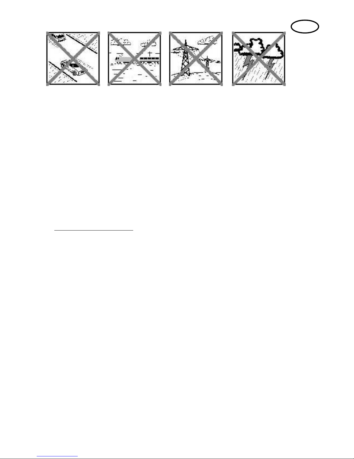
1. Zusammenbau des Rumpfs (KIT)
Klipsen Sie die beiden Teile des Flügelgegenlagers 33 und
34 zusammen und verkleben Sie sie mit Zacki. ! Achtung!
Beim Zusammenkleben /klipsen der Teile kann Klebstoff
herausspritzen. Kleben Sie dann die Canopylock Verschlussklammer 31, das Baldachingegenlager 28 und das
Flügelgegenlager in die rechte Rumpfhälfte 5 ein. Kleben
Sie die beiden Scharnierachsaufnahmen 44 in die Schlitze
der rechten Seitenleitwerkshälfte. Ebenso kleben Sie das
Mutteraufnahme 39 (M5) und das Spornradaufl ager 40 ein.
Abb. 03 + 04
Stecken Sie einen F-Stahldraht 73 durch das Bowdenzug-
rohr 74 und verlegen Sie es in der rechten Rumpfhälfte so,
dass der Bowdenzug den Rumpf hinten verlässt und etwa
30mm übersteht, kleben Sie es fest.
Abb. 05 – 07
Kleben Sie nun noch den vormontierten M-Frame 27 in die
rechte Rumpfhälfte 5 ein.
Abb. 08
In die linke Rumpfhälfte 4 kleben Sie analog zu den vorherigen Schritten die Canopylock-Klammer 31 und das
Baldachingegenlager 28 ein. Anschließend wird auch hier
ein Bowdenzugrohr 74 eingeschobenem F-Stahldraht 73
so verlegt, dass das Rohr am Rumpfende etwa 30mm
heraussteht.
Abb. 09 – 11
Stecken Sie nun die beiden Rumpfhälften OHNE Kleber
zusammen und überprüfen Sie den ordnungsgemäßen
Sitz der Teile. Wenn alles passt, tragen Sie Kleber auf und
fügen Sie die Teile exakt zusammen.
Abb. 12 + 13
Sie können nach diesem Bauschritt die Pilotenpuppe nach
Ihren Wünschen bemalen.
Beachten Sie bitte, dass sich dunkle Flächen unter der
Kabinenhaube bei Sonneneinstrahlung stark erwärmen
können. An diesen Stellen kann das ELAPOR unter Umständen aufpoppen/Blasen bekommen!
Kleben Sie den Instrumentenbrett-Aufkleber (Dekorbogen)
auf das angeformte Panel im Cockpit. Wenn Sie mit der
Gestaltung Ihres Cockpits zufrieden sind, kleben Sie die
Kabinenhaube 26 mit UHU Por auf den Rumpf.
Abb. 14
Kleben Sie die vier Magnete 58 zur Befestigung der Motorhaube 6 an die vorgesehenen Stellen in der Rumpffront.
Abb. 15
Nehmen Sie sich das Seitenruderservo zur Hand und
stellen es mit der Fernsteuerung in Neutralstellung. Bohren
Sie die äußeren Löcher des Servohebels auf Ø 2,5mm auf.
Setzen Sie dann entsprechend Abb. 16 den Servohebel
auf und sichern ihn mit der beiliegenden Servoschraube.
Montieren Sie am Servohebel den Gestängeanschluss 54
mit einer Stoppmutter M2 56 im äußersten Loch. Drehen Sie
oben in den Gestängeanschluss einen Gewindestift M3 55.
Nun setzen Sie das Servo in die linke Aussparung des
M-Frames ein und befestigen es mit den beiliegenden
Schrauben.
Abb. 16
Mit dem Höhenruderservo verfahren Sie analog, jedoch
wird hier der Servohebel um 180° gedreht aufgesetzt.
Das Höhenruderservo montieren Sie dann in der rechten
Aussparung im M-Frame.
Abb. 17
Kleben Sie in die Motorhaube 6 die vier anderen Magnete
58 an ihre vorgesehenen Positionen.
!ACHTUNG!: Stellen Sie sicher, dass sich keines der Ma-
gnetenpaare später abstößt!
Abb. 18
In den Rumpfdeckel 7 kleben Sie beiden CanopylockZapfen 32 in die Schlitze ein.
Abb. 19
2. Zusammenbau des Fahrwerks (KIT+RR)
Kleben Sie in die innere linke der linken Radverkleidungshäfte 18 den linken Radverkleidungshalter 45 ein. Kleben
Sie anschließend die äußere Hälfte der Radverkleidung
19 auf. Mit der rechten Radverkleidung verfahren Sie bitte
analog (Teile 20, 46, 21).
Abb. 20 + 21
Stecken Sie ein Leichtrad 67 in die linke Radverkleidung
und führen Sie dann die Schraube 64 (M4x40) als Radach-
se durch Radverkleidung und Rad. Auf die Schraube drehen
Sie anschließend eine Mutter M4 66 locker auf. Stecken Sie
die Schraube mit einer U-Scheibe 65 nun durch die Bohrung
am linken Bein des Fahrwerksbügels 62 und befestigen Sie
es mit U-Scheiben 65 und Stoppmutter M4 63.
Achtung: „vorne“ beim Fahrwerksbügel ist die gerade Seite! Die Abbildung 47 verdeutlicht das Schema der Montage
noch einmal. Analog dazu wird auch der rechte Radschuh
am Fahrwerksbügel montiert.
Abb. 22
Auf den Fahrwerksbügel kleben Sie mit einem Tropfen
Zacki nun die Fahrwerksabdeckung 22. Prüfen Sie bitte
vor dem Verkleben die Ausrichtung des Teils, indem Sie
Page 7

Seite 7
es an den Rumpf anhalten. Schrauben Sie das fertig zusammengebaute Fahrwerk nun mit vier Inbus-Schrauben
(M4x12) an den Rumpf.
Abb. 23 + 24
Schieben Sie auf den Spornradbügel das Spornrad 70 auf
und sichern Sie es mit dem Stellring 71.
Abb. 25
3. Leitwerke (KIT+RR)
Kleben Sie in die untere Hälfte des Höhenleitwerks 13 vier
Scharnierachsaufnahmen 44 ein. Zwischen die inneren
Scharnierachsaufnahmen kleben Sie die Hülse für die Höhenleitwerksbefestigung 38. Verkleben Sie anschließend
die untere mit der oberen Höhenleitwerkshälfte 12.
Abb. 26
Kleben Sie die Achsen der Hohlkehlenscharniere 43 in
das Höhenruder 14. In den langen Schlitz kleben Sie das
CFK-Rohr 72 (Ø 3mm) ein. Schließen Sie das Höhenruder
durch Einkleben der Höhenruderabdeckung 15 und des
Ruderhorns 49.
Abb. 27
Nun kann das Höhenruder ans Höhenleitwerk angeclipst
werden und in die Aussparung am Rumpf geschoben werden. Gesichert wird es durch eine Kunststoffschraube 48
(M5x60) von unten.
Abb. 28 + 29
Montieren Sie am Ruderhorn einen Gestängeanschluss
53, schieben Sie den F-Stahldraht durch die Bohrung und
sichern Sie ihn bei neutralem Ruder mit einem Gewindestift
M3 55. Abb. 30
Kleben Sie in das Seitenruder 16 ebenfalls zwei Scharnierachsen und das Seitenruderhorn 42 ein. Schließen Sie
dann das Seitenruder mit der Seitenruderabdeckung 17.
Das montierte Seitenruder kann nun ebenfalls am Leitwerk
angeclipst werden. Hängen Sie dazu zuerst das Dornlager
am unteren Ende des Leitwerks ein und clipsen sie dann
die Scharniere ein.
Abb. 31 – 33
Auch am Seitenruderhorn montieren Sie wie beim Höhenruder einen Gestängeanschluss 53 und klemmen den
F-Stahldraht mit dem Gewindestift M3 55 fest.
Abb. 34
4. Motoreinbau (KIT+RR)
Befestigen Sie den Motor mit vier beiliegenden Schrauben
am Alu-Motorspant 59. Verwenden Sie an allen Schrauben einen Tropfen Schraubensicherungslack (mittelfest)!
Schrauben Sie dann den Motor mit Hilfe der Distanzbolzen
61 und vier Schrauben 60 (M4x65) mit U-Scheiben 65 in
den Rumpf.
Abb. 35
Setzen Sie auf die Motorwelle den Luftschraubenmitnehmer
86 mit Spannkonus 87, die Spinnerplatte 85, den Propeller
84, eine U-Scheibe 83 (Innen Ø 6mm) und Mutter M6 82
auf. Ziehen Sie die Mutter leicht an und drehen Sie den
Propeller gegen die Anschläge auf der Spinnerplatte. Hal-
ten Sie den Propeller in Position während Sie die Mutter
vollständig anziehen.
Setzen Sie abschließend die Spinnerkappe 81 auf und
schrauben Sie sie mit zwei Schrauben 81 (3x16mm) an
der Spinnerplatte fest.
Abb. 36
5. Zusammenbau der Trag! ächen (KIT+RR)
Zunächst wird der Baldachin für die obere Tragfläche
montiert. Dazu werden die Baldachinstreben 23 und 24 und
die Hülse für die Flächenbefestigung 35 an das Baldachinzwischenstück 25 geklebt. In die Unterseite der Abdeckung
kleben Sie jeweils die linke und rechte Baldachinarretierung
29 und 30, danach noch die CFK-Leiste 78 (3x1x100mm).
Abb. 37
Kleben Sie in die beiden Tragfl ächenstreben 10 und 11
jeweils oben und unten einen Clip für die Streben 36 ein
und auf der Rückseite eine CFK-Leiste 77 (3x1x190mm).
Achten Sie darauf, dass kein Klebstoff in den Clip fl ießt.
Abb. 38 + 39
In die obere Tragfl äche 8 kleben Sie das Holmrohr 79 und
beidseitig eine Aufnahme für die Strebenclips 37. An den
Querrudern befi nden sich Aussparungen für die Aufnah-
men der Querruderverbinder 50. Kleben Sie auch diese
beidseitig ein.
Abb. 40
Stellen Sie die Querruderservos mittels Ihrer Fernsteuerung
in Neutralposition und schrauben Sie die Servohebel auf.
Kleben Sie die Servos in die untere Tragfl äche 9 an ihre
vorgesehene Position. Verwenden Sie hierzu nur etwas
Heißkleber an den Servolaschen. Die Kabel verlegen Sie
in den dafür vorgesehenen Kabelkanälen und kleben Sie
mit etwas Tesafi lm ab. Außerdem kleben Sie in die Querru-
der beidseitig je ein Ruderhorn 49 und eine Aufnahme für
die Querruderverbinder 50 ein. Im angeformten Rumpfteil
kleben Sie in die Bohrung eine Hülse zur Flächenbefestigung 35.
Abb. 41
Hängen Sie in die Querruderservos jeweils ein Querrudergestänge 75 ein und verbinden Sie es in gewohnter Art
und Weise mit einem Gestängeanschluss 53 und einem
Gewindestift M3 55 mit dem Ruderhorn.
Abb. 42
Verkleben Sie den zusammengebauten Baldachin sorgfältig
mit der oberen Tragfl äche (Ausrichtung beachten!).
Abb. 43
6. Einbau der Empfangsanlage (KIT+RR)
Stecken Sie alle Servokabel in den Empfänger und programmieren Sie das Modell gemäß den angegebenen
Ruderausschlägen. Die Steckerordnung bei MULTIPLEX ist
(sofern nicht anderweitig frei zugeordnet) folgendermaßen:
1. Querruder links
2. Höhenruder
3. Seitenruder
4. Gas
5. Querruder rechts
Page 8

Seite 8
Befestigen Sie den Empfänger mit Klettband auf der Unterseite des M-Frames. Für eine feste Verbindung des
Klettbandes am Holz empfehlen wir ein paar Tropfen Zacki
hinzu zu geben. Zusätzlich können Sie den Empfänger mit
einem Kabelbinder sichern.
7. Endmontage des Flugzeugs (KIT+RR)
Stecken Sie zunächst die untere Fläche an den Rumpf.
Drehen Sie dazu den Rumpf auf den Rücken und führen
Sie die Tragfl äche mit der Nasenleiste in die Ecke zwischen
Fahrwerk und Radverkleidung. Nun schleißen Sie die
Querruderkabel am Empfänger an. Klappen Sie dann die
Endleiste zum Rumpf hin und stecken Sie die Lasche in
den Rumpf. Nun kann die Tragfl äche vollständig angelegt
und mit einer Kunststoffschraube 47 (M5x35) verschraubt
werden.
Stellen Sie das Flugzeug wieder aufs Fahrwerk und clipsen
Sie die Tragfl ächenstreben links und rechts an die untere
Tragfl äche. Stecken Sie nun die obere Tragfl äche mit dem
Baldachin auf den Rumpf und clipsen Sie die Tragfl ächenstreben auch oben fest. Abschließend Verschrauben Sie
auch diese Tragfl äche mit einer Kunststoffschraube 47
(M5x35) mit dem Rumpf.
Abb. 44
Zur Verbindung der Querruder dienen zwei Gestänge aus
Metall 76. Montieren Sie zunächst an allen Aufnahmen
für die Querruderverbinder Gestängeanschlüsse. Dabei
verwenden Sie auf der linken Seite rote Teile 51 und auf
der rechten Seite grüne Teile 52.
Richten Sie die Querruder neutral aus und befestigen Sie
zunächst oben einen Querruderverbinder mit einem Gewindestift M3 55. Wenn oberes und unteres Querruder neutral
stehen, befestigen Sie auch unten den Querruderverbinder
mit einem Gewindestift M3.
Gehen Sie auf der anderen Seite analog vor!
Abb. 45 + 46
Bei der Demontage des Flugzeugs clipsen Sie lediglich
die Gestängeanschlüsse aus ihren Aufnahmen. So bleibt
die gleichmäßige Abstimmung der Querruder zueinander
erhalten. Durch die Farben der Anschlüsse lässt sich sofort
erkennen, auf welche Seite sie gehören:
ROT = links
GRÜN = rechts
8. Auswiegen (KIT+RR)
Kleben Sie zunächst mit Zacki die beiden Trimmgewichte
91 in den Motorraum, sodass sich die Motorhaube noch
schließen lässt.
Schieben Sie den Antriebsakku auf der Akkurutsche so
in Position, dass der Schwerpunkt bei 100 mm liegt
(gemessen von der oberen Trag! ächenvorderkante in
Rumpfnähe). Befestigen Sie den Akku mit den beiliegen-
den Klettbändern 88 und 89 und mit der Klettbandschlaufe
90.
Für eine feste Verbindung des Klettbandes am Rumpfboden empfehlen wir ein paar Tropfen Zacki hinzu zu geben.
9. Empfohlene Ruderausschläge
für klassischen Programmkunstfl ug:
Seitenruder: rechts/links 40 mm 60% EXPO
Höhenruder: hoch 40 mm, runter 40 mm 70%
EXPO
Querruder: hoch 17 mm runter 17 mm 50%
EXPO
Mischer (linear): 3,5mm Querruder auf Seitenruder
entgegengesetzt
àD.h.: bei SR voll rechts, fährt
das QR 3,5mm links
4mm Höhenruder auf Seitenruder
àD.h.: bei SR voll R+L fährt das
HR 4mm nach oben
Für 3D-Kunstfl ug:
Seitenruder: rechts/links: 65 mm 60% EXPO
Höhenruder: hoch / runter: 55mm 70% EXPO
Querruder: hoch 22 mm / runter 22 mm 50%
EXPO
Mischer (linear): 3,5mm Querruder auf Seitenruder
entgegengesetzt
àD.h.: bei SR voll rechts, fährt
das QR 3,5mm links
4mm Höhenruder auf Seitenruder
àD.h.: bei SR voll R+L fährt das
HR 4mm nach oben
Page 9

Seite 9
Stückliste KIT ROCKSTAR # 21 4278 & RR ROCKSTAR # 26 4278:
Lfd.
Kit RR Bezeichnung Material Abmessungen
1 1 1 Bauanleitung KIT Papier 80g/m² DIN-A4
2 1 1 Reklamationsmeldung Modelle Papier 80g/m² DIN-A4
3 1 1 Dekorbogen Klebefolie 700 x 1000mm
4 1 1 Rumpfhälfte links Elapor geschäumt Fertigteil
5 1 1 Rumpfhälfte rechts Elapor geschäumt Fertigteil
6 1 1 Motorhaube Elapor geschäumt Fertigteil
7 1 1 Rumpfdeckel Elapor geschäumt Fertigteil
8 1 1 Tragfl äche oben Elapor geschäumt Fertigteil
9 1 1 Tragfl äche unten Elapor geschäumt Fertigteil
10 1 1 Tragfl ächenstrebe links Elapor geschäumt Fertigteil
11 1 1 Tragfl ächenstrebe rechts Elapor geschäumt Fertigteil
12 1 1 Höhenleitwerk oben Elapor geschäumt Fertigteil
13 1 1 Höhenleitwerk unten Elapor geschäumt Fertigteil
14 1 1 Höhenruder Elapor geschäumt Fertigteil
15 1 1 Höhenruderabdeckung Elapor geschäumt Fertigteil
16 1 1 Seitenruder Elapor geschäumt Fertigteil
17 1 1 Seitenruderabdeckung Elapor geschäumt Fertigteil
18 1 1 Radverkleidung links innen Elapor geschäumt Fertigteil
19 1 1 Radverkleidung links aussen Elapor geschäumt Fertigteil
20 1 1 Radverkleidung rechts innen Elapor geschäumt Fertigteil
21 1 1 Radverkleidung rechts aussen Elapor geschäumt Fertigteil
22 1 1 Fahrwerksabdeckung Elapor geschäumt Fertigteil
23 1 1 Baldachin links Elapor geschäumt Fertigteil
24 1 1 Baldachin rechts Elapor geschäumt Fertigteil
25 1 1 Baldachin-Zwischenstück Elapor geschäumt Fertigteil
26 1 1 Kabinenhaube Kunststoff, tiefgezogen Fertigteil
27 1 1 Motordom Tornado komplett Lindensperrholz 3mm Fertigteil
28 4 4 Baldachin-Gegenlager Lindensperrholz 3mm Fertigteil
29 1 1 Baldachin-Arretierung links Kunststoff gespritzt Fertigteil
30 1 1 Baldachin-Arretierung rechts Kunststoff gespritzt Fertigteil
31 2 2 Verschlussklammer Kunststoff gespritzt Fertigteil
32 2 2 Verschlusszapfen Kunststoff gespritzt Fertigteil
33 2 2 Flügelgegenlager A Kunststoff gespritzt Fertigteil M5
34 2 2 Flügelgegenlager B Kunststoff gespritzt Fertigteil M5
35 2 2 Hülse Flächenbefestigung Kunststoff gespritzt Fertigteil
36 4 4 Clip Flächenstrebe Kunststoff gespritzt Fertigteil
37 4 4 Clipaufnahme Flächenstrebe Kunststoff gespritzt Fertigteil
38 1 1 Hülse Höhenleitwerksbefestigung Kunststoff gespritzt Fertigteil
39 1 1 Mutteraufnahme (M5) Kunststoff gespritzt Fertigteil
40 1 1 Spornradaufl ager Kunststoff gespritzt Fertigteil
41 1 1 Klemmstück Spornradaufl ager Kunststoff gespritzt Fertigteil
42 1 1 Seitenruderhorn Kunststoff gespritzt Fertigteil
43 6 6 Hohlkehlscharnier Achse Kunststoff gespritzt Fertigteil
44 6 6 Hohlkehlscharnier Achsaufnahme Kunststoff gespritzt Fertigteil
45 1 1 Radverkleidungshalter links Kunststoff gespritzt Fertigteil
46 1 1 Radverkleidungshalter rechts Kunststoff gespritzt Fertigteil
47 2 2 Zylinderschraube Kunststoff Kunststoff M5 x 35mm
48 1 1 Kunststoff-Zylinderschraube Polyamid M5 x 60mm
Page 10

Seite 10
Lfd.
Kit RR Bezeichnung Material Abmessungen
49 3 3 Ruderhorn „Twin“ Kunststoff gespritzt Fertigteil
50 4 4 Aufnahme Kardanbolzen-Querruderverb. Kunststoff gespritzt Fertigteil
51 2 2 Kardanbolzen ROT Metall Ø6 x 8mm
52 2 2 Kardanbolzen GRÜN Metall Ø6 x 8mm
53 4 4 Kardanbolzen KLAR Metall Ø6 x 8mm
54 2 2 Gestängeanschluss KLAR Metall Ø6 x 8mm
55 11 11 Inbus-Gewindestift Metall M3 x 3mm
56 2 2 Stop-Mutter Metall M2
57 1 1 Mutter Metall M5
58 8 8 Magnet Neodym 5 x 2 x 10mm
59 1 1 Alu-Motorspant Alu Fertigteil
60 4 4 Inbusschraube Motorspantbefestigung, Metall M4 x 65mm
61 4 4 Distanzbolzen Motorspant Alu Fertigteil
62 1 1 Fahrwerksbügel Alu Fertigteil
63 2 2 Stoppmutter Metall M4
64 2 2 Schraube für Radachse Metall M4 x 40mm
65 8 8 U-Scheibe Metall innen Ø 4mm
66 2 2 Muttern Radachsbefestigung Metall M4
67 2 2 Leichtrad Kunststoff Ø73mm
68 4 4 Inbusschraube Metall M4 x 12mm
69 1 1 Spornradbügel F-Stahl Ø1,5 x 210mm
70 1 1 Leichtrad für Heckfahrwerk Moosgummi Ø26 mm
71 1 1 Stellring für Spornrad Metall innen Ø 2mm
72 1 1 CFK-Rohr Metall Ø3 x 370mm
73 2 2 F-Stahldraht Metall Ø1,2 x 740mm
74 2 2 Bowdenzugrohre Kunststoff Ø3 x 590mm
75 2 2 Querrudergestänge m.Z Metall Ø1,3 x 70mm
76 2 2 Querruderverbinder Metall Ø1,5 x 210mm
77 2 2 CFK-Leiste Flächenstrebe CFK 3 ,0 x 1,0 x 190
78 1 1 CFK-Leiste Mittelstrebe CFK 3,0 x 1,0 x 100
79 1 1 Holmrohr GFK-Rohr Ø8 x 800mm
80 2 2 Spinnerschrauben Metall 3 x 16mm
81 1 1 Spinnerkappe Kunststoff gespritzt Ø62mm
82 1 1 Mutter Metall M6
83 1 1 U-Scheibe Metall innen Ø 6mm
84 1 1 Propeller Kunststoff gespritzt 14 x 7“
85 1 1 Spinnergrundplatte Kunststoff gespritzt Ø62mm
86 1 1 Luftschraubenmitnehmer Metall Fertigteil
87 1 1 Spannkonus Metall Fertigteil
88 3 3 Klettband Pilzkopf Kunststoff 25 x 60mm
89 3 3 Klettband Velours Kunststoff 25 x 60mm
90 1 1 Klettschlaufe Kunststoff 25 x 200mm
91 2 2 Trimmgewicht Metall 25 x 19 x 5mm
92 0 4 Motorbefestigungsschrauben Metall 3 x 8mm
93 0 1 Motor Himax 4220-620
94 0 4 Servos HiTec HS-82MG
95 0 1 Regler MULTIcont BL-60 SD
Page 11

Seite 11
Safety Information for MULTIPLEX model aircraft
This model is NOT A TOY in the usual sense of the term.
By operating the model the owner affi rms that he is aware of the content of the operating instructions, especially those
sections which concern safety, maintenance, operating restrictions and faults, and is capable of fulfi lling these requirements.
This model must not be operated by any child under fourteen years of age. If a person below this age operates the model
under the supervision of a competent adult who is acting as the child’s guardian within the legal sense of the term, this
individual is responsible for the implementation of the information in the OPERATING INSTRUCTIONS.
THE MODEL AND ASSOCIATED ACCESSORIES MUST BE KEPT OUT OF THE REACH OF CHILDREN UNDER THREE
YEARS OF AGE! MODELS CONTAIN SMALL DETACHABLE PARTS WHICH MAY BE SWALLOWED BY CHILDREN
UNDER THREE YEARS. CHOKING HAZARD!
All the warnings in the OPERATING INSTRUCTIONS must be observed whenever the model is operated. Multiplex
Modellsport GmbH & Co. KG accepts no liability for loss or damage or any kind which occurs as a result of incorrect
operation or misuse of this product, including the accessories required for its operation. This includes direct, indirect,
deliberate and accidental loss and damage, and all forms of consequent damage.
Every safety note in these instructions must always be observed, as all the information contributes to the safe operation of your model. Use your model thoughtfully and cautiously, and it will give you and your spectators many hours of
pleasure without constituting a hazard. Failure to operate your model in a responsible manner may result in signifi cant
property damage and severe personal injury. You alone bear the responsibility for the implementation of the operating
instructions and the safety notes.
Approved usage
The model is approved exclusively for use within the modelling hobby. It is prohibited to use the model for any other
purpose than that stated. The operator of the model, and not the manufacturer, is responsible for damage or injury of
any kind resulting from non-approved use.
The model may only be operated in conjunction with those accessories which we expressly recommend. The recommended components have undergone thorough testing, are an accurate match to the model, and ensure that it functions
safely. If you use other components, or modify the model, you operate it at your own risk, and any claim under guarantee
is invalidated.
To minimise the risk when operating the model, please observe the following points:
l The model is guided using a radio control system. No radio control system is immune to radio interference, and
such interference may result in loss of control of the model for a period of time. To avoid collisions, you must
therefore ensure at all times that there is a wide margin of safety in all directions when operating your model. At
the slightest sign of radio interference you must cease operating your model!
l Never operate your model until you have successfully completed a thorough check of the working systems, and
carried out a range-check as stipulated in the instructions supplied with your transmitter.
l The model may only be fl own in conditions of good visibility. You can avoid being temporarily blinded by not fl ying
towards the sun, or in other diffi cult light conditions.
l A model must never be operated by a person who is under the infl uence of alcohol, drugs or medication which
have an adverse effect on visual acuity and reaction time.
l Only fl y your model in conditions of wind and weather in which you are able to maintain full control of the model.
Even when the wind is light, bear in mind that turbulence can form at and around objects which may have an
effect on the model.
l Never fl y in any location where you may endanger yourself of others, e.g. close to residential areas, overhead
cables, open roads and railway lines.
l Never fl y towards people or animals. You may think that fl ying low over other people’s heads is proof of your
piloting skill, but all it does is place others at unnecessary risk. It is in all our interests that you let other pilots
know that this is what you think. Always fl y in such a way that you do not endanger yourself or others. Bear in
mind that even the best RC system in the world is subject to outside interference. No matter how many years of
accident-free fl ying you have under your belt, you have no idea what will happen in the next minute.
GB
Page 12

Seite 12
Residual risks
Even if the model is operated in the correct manner, and you observe all safety aspects, there is always a certain residual
risk.
For this reason it is mandatory to take out third-party liability insurance. If you join a club or fl ying association, insurance
is usually available or included in the annual fee. Make sure that your insurance cover is adequate (i.e. that it covers
powered model aircraft). Always keep your models and your radio control equipment in perfect order.
The following hazards may occur owing to the model’s construction and type:
l Injury caused by the propeller: you must keep well clear of the area around the propeller from the moment that
the battery is connected. Please bear in mind that objects in front of the propeller may be sucked into it, and
objects behind the propeller may be blown away by it. The model may start moving when the propeller starts
to turn. You must therefore position the model in such a way that it cannot move towards other persons if the
motor should unexpectedly start running. When you are carrying out adjustment work involving the running
motor, you must ensure that the model is always held securely by an assistant.
l Crash caused by pilot error: this can happen even to the best of pilots, so it is essential to fl y exclusively in a
safe environment: an approved model fl ying site and suitable insurance are basic essentials.
l Crash caused by technical failure or unnoticed damage in transit or in the workshop. A thorough check of the
model before every fl ight is essential. However, you should also take into account at all times that material
failures can and do occur. Never fl y in a location where your model may damage or injure others.
l Keep within the stated operating limits. Excessively violent fl ying will weaken the airframe, and may result in
sudden material failure, or may cause the model to crash during a subsequent fl ight due to “creeping” consequent damage.
l Fire hazard caused by electronic failure or malfunction. Store batteries safely, and always observe safety
notes which apply to the airborne electronic components, the battery and the battery charger. Protect all electronic equipment from damp. Ensure that the speed controller and battery are adequately cooled.
The instructions which accompany our products must not be reproduced and / or published, in full or in part, in
print or any electronic medium, without the express written approval of Multiplex Modellsport GmbH & Co. KG.
GB
Page 13

Seite 13
Examine your kit carefully!
MULTIPLEX model kits are subject to constant quality checks throughout the production process, and we sincerely
hope that you are completely satisfi ed with the contents of your kit. However, we would ask you to check all the parts
before you start construction, as we cannot exchange components which you have already worked on. If you fi nd
any part is not acceptable for any reason, we will readily correct or exchange it. Just send the component to our Model
Department. Please be sure to include the purchase receipt and a brief description of the fault.
We are constantly working on improving our models, and for this reason we must reserve the right to change the kit
contents in terms of shape or dimensions of parts, technology, materials and fi ttings, without prior notifi cation. Please
understand that we cannot entertain claims against us if the kit contents do not agree in every respect with the instructions and the illustrations.
Caution!
Radio-controlled models, and especially model aircraft, are by no means playthings. Building and operating them
safely requires a certain level of technical competence and manual skill, together with discipline and a responsible attitude at the " ying # eld. Errors and carelessness in building and " ying the model can result in serious
personal injury and damage to property. Since we, as manufacturers, have no control over the construction,
maintenance and operation of our products, we are obliged to take this opportunity to point out these hazards
and to emphasise your personal responsibility.
Warning:
Like every aeroplane, this model has static limits. Steep dives and senseless manoeuvres inappropriate to the type
may result in the loss of the aircraft. Please note: we will not replace the model in such cases. It is your responsibility to
approach the airframe’s limits gradually. It is designed for the power system recommended in these instructions, but is
only capable of withstanding the fl ight loads if built exactly as described and if it is in an undamaged state.
Recommended equipment:
Zacki ELAPOR 20g VE1 RR+KIT Item number: 852727
Li-BATT FX 4/1 2600 (M6) RR+KIT Item number: 157362
Receiver RX-5 light M-LINK 2,4 GHz RR+KIT Item number: 55808
Drive set ROCKSTAR KIT Item number: 332667
Servo HS-82 MG (4x) KIT Item number: 112088
Extension lead 15 cm (UNI) (2x) KIT Item number: 85019
GB
Page 14

Seite 14
Important note
This model is not made of Styrofoam™, and it is not possible to glue the material using white glue, polyurethane or
epoxy; these adhesives only produce superfi cial joints, and simply break away under stress. Please be sure to use
medium-viscosity cyano-acrylate glue exclusively, preferably Zacki ELAPOR® # 59 2727, which is optimised specifi cally
for ELAPOR® particle foam. If you se Zacki ELAPOR® there is usually no need for cyano ‘kicker’ or activator. However,
if you wish to use a different adhesive which requires the use of activator, please note that these materials are injurious
to health, and should always be applied in the open air. Take care when handling all cyano-acrylate adhesives, as they
harden in seconds, so don’t get them on your fi ngers or other parts of the body. We strongly recommend the use of
goggles to protect your eyes. Keep the adhesive out of the reach of children! For certain joints it is also possible to use
hot-melt adhesive; the instructions indicate where this is the case.
Working with Zacki ELAPOR®
Zacki ELAPOR® has been developed specifi cally for glued joints in our models which consist of moulded ELAPOR®
foam parts.
Please observe the following points in order to obtain perfect joints:
• Avoid the use of activator. ‘Kicker’ signifi cantly weakens the joint. We advise leaving joined parts for 24 hours to obtain
maximum strength, particularly when the glued area is large.
• Activator should only be used for temporary, small-area joints (‘tacking’). Spray a little activator on one surface, and
allow it to air-dry for about thirty seconds.
• To obtain maximum joint strength you should lightly sand the surface with 320-grit abrasive paper before applying glue.
Bent parts - actually don’t exist. If you ! nd that a component has taken up a curve, perhaps after being transported, it is easy to straighten again. In this respect ELAPOR® behaves in a similar way to metal: bend the
component back slightly beyond the correct position, and the material will then spring back to its proper shape
when released, and maintain it. There are limits, however - don’t overdo it"
Bent parts - really do exist. If you wish to paint your model, apply MPX Primer # 60 2700 to the surfaces, wiping it on
very lightly as if you were cleaning the model. Paint must always be applied thinly and evenly, otherwise the component
will warp. Then you really will have bent parts, and they will also be heavy and perhaps even unusable. We have found
that matt-fi nish paints produce the best visual effect.
Technical information ROCKSTAR:
Wingspan: 1050 mm
Overall length: 1060 mm
All-up weight: 1800 g
Total surface area: 48 dm²
Wing loading: 38 g/dm²
Channels: 5
RC Functions: rudder, elevator, aileron, motor
Flight time: ca. 7 min (4S ~2600 mAh)
Note: please remove the pictures from the center of the instructions"
Page 15

Seite 15
Congratulations on your new ROCKSTAR!
You will need the following tools to build the model:
2 x Zacki-Elapor # 85 2727 (KIT) (1xRR)
1 x UHU Por (KIT)
Hot glue gun (KIT)
Medium-sized cross-point screwdriver (KIT)
Medium-sized slot-head screwdriver (KIT)
Balsa knife (KIT)
Pointed-nose pliers (KIT)
1.5 mm A/F allen key (KIT)
3 mm A/F allen key (KIT)
10 mm A/F open-ended spanner (KIT)
2.5 mm drill (KIT)
Before starting construction:
Please check that all the parts are present, referring to the
Parts List on page 18+19 (Figs. 01 & 02).
1. Assembling the fuselage (KIT)
Clip together the two parts 33 and 34 which form the spread-
er plate for the wing retaining bolt, and glue the joint with
Zacki. ! Caution ! Watch out for excess glue squirting out
when the parts are joined. Glue the Canopy Lock clip 31,
the cabane socket 28 and the wing bolt spreader plate in
the right-hand fuselage shell 5. Glue the two rudder hinge
pin supports 44 in the slots in the right-hand fi n shell. At the
same time glue the M5 nut support 39 and the tailwheel
bracket 40 in place.
Figs. 03 + 04
Slip a length of spring steel wire 73 through the snake outer sleeve 74, and lay it in the right-hand fuselage shell as
shown; the snake outer should project about 30 mm from
the tail end of the fuselage. Glue it in place permanently.
Figs. 05 – 07
Now glue the pre-assembled M-Frame 27 in the right-hand
fuselage shell 5.
Fig. 08
Working in a similar manner, glue the following parts in the
left-hand fuselage shell 4: the Canopy Lock clip 31 and the
cabane socket 28. A second spring steel rod 73 should now
be slipped into a snake outer sleeve 74, and fi tted in the
left-hand fuselage shell; this should also project at the tail
end by about 30 mm.
Figs. 09 – 11
Now offer up the two fuselage shells to each other dry
(WITHOUT glue), and check that they fi t together snugly at
all points. When you are confi dent that everything matches
up correctly, apply glue to the joint surfaces, fi t the two shells
together, and check that they are accurately aligned.
Figs. 12 + 13
With this step complete, it is time to paint the dummy pilot
in the colour scheme of your choice.
Please note that dark areas under the canopy may heat
up strongly if subjected to direct sunshine. If this should
happen, the ELAPOR foam may swell and bubble!
Apply the instrument panel sticker (decal sheet) to the
moulded-in binnacle inside the cockpit. When you are sat-
isfi ed with the appearance of your cockpit, glue the canopy
26 to the fuselage using UHU Por.
Fig. 14
Locate the four magnets 58 which retain the cowl 6, and glue
them in the appropriate recesses at the front of the fuselage.
Fig. 15
Hold the rudder servo in your hand and centre it from the
transmitter. Drill out the outermost hole in the servo output
arm using a 2.5 mm Ø bit. Fit the output arm on the servo
shaft as shown in Fig. 16, and secure it with the output
screw. Mount the swivel pushrod connector 54 in the outer
hole in the output arm, securing it with the M2 self-locking nut
56. Fit an M3 grubscrew 55 in the open end of the pushrod
connector barrel.
Place the servo in the opening in the left-hand side of the
M-Frame, and secure it with the retaining screws supplied
with the servo.
Fig. 16
Repeat the procedure with the elevator servo, with this exception: fi t the output arm on the servo facing the opposite
direction. Install the elevator servo in the right-hand opening
in the M-Frame.
Fig. 17
Glue the four remaining magnets 58 in the appropriate
recesses in the cowl 6.
! CAUTION !: Ensure that the pairs of magnets attract,
rather than repel!
Fig. 18
Glue the two Canopy Lock lugs 32 in the slots in the fuselage hatch 7.
Fig. 19
2. Assembling the undercarriage (KIT+RR)
Glue the left-hand wheel spat holder 45 in the inboard lefthand wheel spat shell 18, then glue the outboard wheel spat
shell 19 to the inboard shell. Repeat the procedure with the
right-hand wheel spat (parts 20, 46 and 21).
Figs. 20 + 21
Place one lightweight wheel 67 in the left-hand wheel spat,
then slip the wheel axle (M4 x 40 mm machine screw) 64
through the spat and wheel. Fit an M4 nut 66 loosely on the
end of the screw. Fit a washer 65 on the screw, then slip it
through the hole in the left-hand leg of the undercarriage
unit 62 before securing it with a further washer 65 and an
M4 self-locking nut 63.
Caution: the straight edge of the undercarriage unit is
“forward”! Fig. 47 clearly shows the correct orientation of
the undercarriage. Repeat the procedure with the righthand wheel spat, and attach it to the right-hand leg of the
undercarriage unit in the same way.
Fig. 22
The next step is to glue the undercarriage fairing 22 to the
metal undercarriage unit with a drop of Zacki, but fi rst check
the correct position of the fairing by holding the undercarriage on the fuselage. The completed undercarriage unit
can now be fi xed to the fuselage using four M4 x 12 mm
socket-head screws. Figs. 23 + 24
Page 16

Seite 16
Fit the tailwheel 70 on the axle of the tailwheel unit, and
secure it with the collet 71.
Fig. 25
3. Tail panels (KIT+RR)
Glue four hinge pin supports 44 in the bottom half of the
tailplane 13. Glue the sleeve 38 for the tailplane retainer
screw between the inboard hinge pin supports as shown,
then glue the bottom tailplane shell 13 to the top tailplane
shell 12.
Fig. 26
Glue the recessed hinge pin units 43 in the elevator 14. Glue
the 3 mm Ø carbon fi bre tube 72 in the long slot. Close the
elevator by gluing the cover 15 in place, followed by the
elevator horn 49.
Fig. 27
The hinges can now be clipped together to attach the elevator to the tailplane. Slide the tailplane assembly into the
slot in the fuselage, and secure it by fi tting the plastic M5 x
60 retaining screw 48 from the underside.
Figs. 28 + 29
Attach a swivel pushrod connector 53 to the elevator horn
and slip the spring steel pushrod through the hole in the
barrel. Set the elevator to neutral (centre), then tighten the
M3 grubscrew 55 in the barrel to clamp the pushrod in place.
Fig. 30
Glue two hinge pin units 43 and the rudder horn 42 in the
rudder 16, then close the rudder by gluing the cover 17 in
place. The completed rudder can now also be attached to
the fi n: fi rst engage the spigot which forms the bottom fi n
hinge, then clip the two upper hinges together.
Figs. 31 – 33
Mount a swivel pushrod connector 53 on the rudder horn
as described for the elevator, and clamp the spring steel
pushrod in the barrel using an M3 grubscrew 55.
Fig. 34
4. Installing the motor (KIT+RR)
Attach the motor to the aluminium mount 59 using the four
screws supplied, not forgetting to apply a drop of medi-
um-strength thread-lock fl uid to each screw! Now install the
motor in the fuselage using the stand-off pillars 61 and four
M4 x 65 mm machine screws 60 and washers 65.
Fig. 35
Fit the propeller driver 86 on the motor shaft together with
the taper collet 87, the spinner backplate 85, the propeller
84, a 6 mm I.D. washer 83 and the M6 nut 82. Tighten the
retaining nut lightly, then rotate the propeller until it rests
against the spinner backplate’s integral bosses. Hold the
propeller in this position while you tighten the retaining nut
fully.
Fit the spinner cap 81 over this assembly, and fi x it to the
spinner backplate using two 3 x 16 mm screws 81.
Fig. 36
5. Completing the wings (KIT+RR)
The fi rst step is to assemble the cabane for the top wing:
glue the cabane struts 23 and 24 and the wing bolt sleeve
35 to the cabane core 25. Glue the left and right cabane
retainers 29 and 30 in the underside of the cover, followed
by the 3 x 1 x 100 mm CFRP strip 78.
Fig. 37
Glue the strut clips 36 to both ends of the two wing struts
10 and 11, and glue a 3 x 1 x 190 mm CFRP strip 77 on
the inboard face of each strut. Take care that no glue runs
into the strut clips.
Figs. 38 + 39
Glue the tubular spar 79 in the channel in the underside of
the top wing 8, and a socket 37 for the strut clips on each
side. You will fi nd recesses in the ailerons for the aileron link
rod supports 50; glue these in place on both sides.
Fig. 40
Centre the aileron servos from your transmitter before
screwing the output arms to the output shafts. The servos
should be glued in the openings in the bottom wing 9,
applying just a little hot-melt glue to the servo mounting
lugs. Deploy the servo leads in the cable ducts, and apply
adhesive tape over the open slots to seal them. Glue a
horn 49 and an aileron link rod support 50 in each aileron.
Locate the hole in the central wing fairing for the wing bolt,
and glue the sleeve 35 in it.
Fig. 41
Connect the pre-formed end of the aileron pushrods 75 to
the aileron servos, and connect them to the aileron horns
in the usual manner, using the swivel pushrod connectors
53 and M3 grubscrews 55.
Fig. 42
Carefully glue the cabane assembly to the underside of the
top wing as shown, ensuring that it fi ts the correct way round!
Fig. 43
6. Installing the receiving system (KIT+RR)
Connect all the servo leads to the receiver, and program the
model memory to give the recommended control surface
travels. Unless you have changed the channel assignment
at the transmitter, the standard sequence for MULTIPLEX
radio systems is as follows:
1. L.H. aileron
2. Elevator
3. Rudder
4. Throttle
5. R.H. aileron
Fix the receiver to the bottom of the M-Frame using hookand-loop tape. A few drops of Zacki will ensure that the
tape adheres fi rmly to the wood. The receiver can also be
secured with a cable-tie.
Page 17

Seite 17
7. Final airframe assembly (KIT+RR)
The fi rst step is to attach the bottom wing to the fuselage:
turn the fuselage onto its back, then guide the leading edge
of the wing into the corner between the undercarriage and
the undercarriage fairing. Connect the aileron lead to the
receiver, then fold the wing’s trailing edge down onto the
wing saddle, and engage the locating lug in the fuselage.
The wing can now be fi nally positioned, and fi xed to the
fuselage using a single M5 x 35 mm plastic screw 47.
Turn the aircraft right side up so that it stands on its undercarriage, and clip the wing struts to the bottom wing on
each side. The top wing and cabane can now be fi tted on
the fuselage, and the top end of the wing struts clipped in
place. The fi nal step is to secure the top wing with a second
M5 x 35 mm plastic screw 47.
Fig. 44
Two metal rods 76 are used to link the top and bottom aile-
rons: fi rst attach swivel pushrod connectors to all four aileron
link rod supports. Note that the red parts 51 belong on the
left-hand side, and the green parts 52 on the right-hand side.
Centre the ailerons from the transmitter before attaching
one aileron link rod at the top using an M3 grubscrew 55.
Clamp the link rod at the bottom with a further M3 grubscrew,
taking care to keep both ailerons centred.
Repeat the procedure on the other side.
Figs. 45 + 46
When dismantling the model, simply unclip the swivel
pushrod connector barrels from their supports; this method
maintains the correct alignment of the ailerons relative to
each other. The colour of the connectors makes it easy to
see the side to which they belong:
RED = left
GREEN = right
8. Balancing (KIT+RR)
First glue the two ballast weights 91 in the motor compartment with Zacki; check that the cowl can still be closed.
Slide the fl ight battery into the battery tray, and adjust its
position until the model balances at the recommended Centre of Gravity (100 mm back from the top wing leading
edge, measured adjacent to the fuselage). Fix the battery
in place using the strips of hook-and-loop tape 88 and 89
and the hook-and-loop strap 90.
To ensure a strong joint, we recommend applying a few
drops of Zacki to the hook-and-loop tape where it makes
contact with the bottom of the fuselage.
9. Recommended control surface travels
for the classic aerobatic schedule:
Rudder: 40 mm right / left, 60% EXPO
Elevator: 40 mm up, 40 mm down, 70%
EXPO
Ailerons: 17 mm up, 17 mm down, 40%
EXPO
Mixer (linear): 3,5mm aileron to rudder, opposite
travel
ài.e.: ailerons defl ect left by
3,5mm at full right-rudder
For 3D aerobatics:
Rudder: 65 mm right / left, 60% EXPO
Elevator: 55 mm up / 55 mm down, 70%
EXPO
Ailerons: 22 mm up / 22 mm down, 50%
EXPO
Mixer (linear): 3,5mm aileron to rudder, opposite
travel
ài.e.: ailerons defl ect left by
3,5mm at full right-rudder
4mm elevator to rudder
ài.e.: elevator defl ects up by
4mm at full right /left -rudder
Page 18

Seite 18
Partlist KIT ROCKSTAR # 21 4278 and RR ROCKSTAR # 26 4278:
No. Kit RR Description Material Dimensions
1 1 1 KIT building instructions Paper 80 g/m² DIN-A4
2 1 1 Model complaints form Paper 80 g/m² DIN-A4
3 1 1 Decal sheet Printed self-adhesive fi lm 700 x 1000mm
4 1 1 L.H. fuselage shell Moulded Elapor foam Ready made
5 1 1 R.H. fuselage shell Moulded Elapor foam Ready made
6 1 1 Cowl Moulded Elapor foam Ready made
7 1 1 Fuselage hatch Moulded Elapor foam Ready made
8 1 1 Top wing Moulded Elapor foam Ready made
9 1 1 Bottom wing Moulded Elapor foam Ready made
10 1 1 L.H. wing strut Moulded Elapor foam Ready made
11 1 1 R.H. wing strut Moulded Elapor foam Ready made
12 1 1 Tailplane, top Moulded Elapor foam Ready made
13 1 1 Tailplane, bottom Moulded Elapor foam Ready made
14 1 1 Elevator Moulded Elapor foam Ready made
15 1 1 Elevator cover Moulded Elapor foam Ready made
16 1 1 Rudder Moulded Elapor foam Ready made
17 1 1 Rudder cover Moulded Elapor foam Ready made
18 1 1 L.H. inboard wheel spat shell Moulded Elapor foam Ready made
19 1 1 L.H. outboard wheel spat shell Moulded Elapor foam Ready made
20 1 1 R.H. inboard wheel spat shell Moulded Elapor foam Ready made
21 1 1 R.H. outboard wheel spat shell Moulded Elapor foam Ready made
22 1 1 Central undercarriage fairing Moulded Elapor foam Ready made
23 1 1 L.H. cabane strut Moulded Elapor foam Ready made
24 1 1 R.H. cabane strut Moulded Elapor foam Ready made
25 1 1 Cabane core Moulded Elapor foam Ready made
26 1 1 Canopy Vac.-moulded plastic Ready made
27 1 1 Tornado motor dome, complete Lime plywood, 3 mm Ready made
28 4 4 Cabane socket Lime plywood, 3 mm Ready made
29 1 1 L.H. cabane retainer Inj.-moulded plastic Ready made
30 1 1 R.H. cabane retainer Inj.-moulded plastic Ready made
31 2 2 Canopy Lock clip Inj.-moulded plastic Ready made
32 2 2 Canopy Lock lug Inj.-moulded plastic Ready made
33 2 2 Wing bolt spreader plate A Inj.-moulded plastic Ready made,M5
34 2 2 Wing bolt spreader plate B Inj.-moulded plastic Ready made,M5
35 2 2 Wing bolt sleeve Inj.-moulded plastic Ready made
36 4 4 Wing strut clip Inj.-moulded plastic Ready made
37 4 4 Wing strut clip socket Inj.-moulded plastic Ready made
38 1 1 Tailplane retainer screw sleeve Inj.-moulded plastic Ready made
39 1 1 M5 nut support Inj.-moulded plastic Ready made
40 1 1 Tailwheel bracket Inj.-moulded plastic Ready made
41 1 1 Tailwheel bracket clamp Inj.-moulded plastic Ready made
42 1 1 Rudder horn Inj.-moulded plastic Ready made
43 6 6 Recessed hinge pin unit Inj.-moulded plastic Ready made
44 6 6 Recessed hinge pin support Inj.-moulded plastic Ready made
45 1 1 L.H. wheel spat holder Inj.-moulded plastic Ready made
46 1 1 R.H. wheel spat holder Inj.-moulded plastic Ready made
47 2 2 Plastic cheesehead screw Plastic M5 x 35mm
48 1 1 Plastic cheesehead screw Nylon M5 x 60mm
Page 19

Seite 19
No. Kit RR Description Material Dimensions
49
3 3 „Twin“ control surface horn Inj.-moulded plastic Ready made
50 4 4 Aileron link rod barrel support Inj.-moulded plastic Ready made
51 2 2 Swivel barrel RED Metal 6 Ø x 8mm
52 2 2 Swivel barrel GREEN Metal 6 Ø x 8mm
53 4 4 Swivel barrel CLEAR Metal 6 Ø x 8mm
54 2 2 Swivel barrel CLEAR Metal 6 Ø x 8mm
55 11 11 Socket-head grubscrew Metal M3 x 3mm
56 2 2 Self-locking nut Metal M2
57 1 1 Nut Metal M5
58 8 8 Magnet Neodymium 5 x 2 x 10mm
59 1 1 Aluminium motor mount Aluminium Ready made
60 4 4 Socket-head screw, motor bulkhead mounting, Metal M4 x 65mm
61 4 4 Motor bulkhead stand-off pillar Aluminium Ready made
62 1 1 Main undercarriage unit Aluminium F38 Ready made
63 2 2 Self-locking nut Metal M4
64 2 2 Machine screw for wheel axle Metal M4 x 40mm
65 8 8 Washer Metal 4mm I.D.
66 2 2 Wheel axle retaining nut Metal M4
67 2 2 Lightweight wheel Plastic 73mm Ø
68 4 4 Socket-head screw Metal M4 x 12mm
69 1 1 Tailwheel unit Spring steel 1.5Ø x 210mm
70 1 1 Lightweight tailwheel Foam rubber 26mm Ø
71 1 1 Tailwheel collet Metal 2mm I.D.
72 1 1 CFRP tube, 3 Ø Metal 3 Ø x 370mm
73 2 2 Spring steel wire Metal 1.2Ø x 740mm
74 2 2 Snake outer sleeve Plastic 3 Ø x 590mm
75 2 2 Pre-formed aileron pushrod Metal (1.4310) 1.3 Ø x 70mm
76 2 2 Aileron link rod Metal (1.4310) 1.5Ø x 210mm
77 2 2 CFRP strip, wing strut CFRP 3x1 x 190mm
78 1 1 CFRP strip, central strut CFRP 3x1 x 100mm
79 1 1 Tubular spar GRP tube 8 Ø x 800mm
80 2 2 Spinner retaining screw Metal 3 x 16mm
81 1 1 Spinner cap Inj.-moulded plastic 62mm Ø
82 1 1 Nut Metal M6
83 1 1 Washer Metal 6mm I.D.
84 1 1 Propeller Inj.-moulded plastic 14 x 7“
85 1 1 Spinner backplate Inj.-moulded plastic 62mm Ø
86 1 1 Propeller driver Metal Ready made
87 1 1 Taper collet Metal Ready made
88 3 3 Hook-and-loop tape, hook Plastic 25 x 60mm
89 3 3 Hook-and-loop tape, loop Plastic 25 x 60mm
90 1 1 Hook-and-loop strap Plastic 25 x 200mm
91 2 2 Ballast weight Metal 25 x 19x5mm
92 0 4 Motor mount screws Metal 3 x 8mm
93 0 1 Motor Himax 4220-620
94 0 4 Servos HiTec HS-82MG
95 0 1 ESC MULTIcont BL-60 SD
Page 20

Seite 20
Consignes de sécurités pour les modèles volants MULTIPLEX
Le modèle n’est PAS UN JOUET.
En utilisant ce modèle, le propriétaire de celui-ci déclare avoir pris connaissance du contenu de la notice d’utilisation,
particulièrement concernant les consignes de sécurités, l’entretien ainsi que les restrictions et défauts d’utilisations, et
qu’il a bien compris le sens de ces consignes
Ce modèle ne doit pas être utilisé par des enfants de moins de 14 ans. Si des personnes mineures devaient utiliser ce
modèle sous la surveillance d’une personne responsable, au sens légal du terme, et expérimentée, celui-ci porte donc
la responsabilité concernant le respect des consignes contenu dans la NOTICE D’UTISATION!
LE MODÈLE AINSI QUE TOUT L’ÉQUIPEMENT NÉCESSAIRE DOIT ÊTRE ÉLOIGNÉ DES ENFANTS DE MOINS DE
3 ANS! LES PARTIES AMOVIBLES DU MODÈLE PEUVENT ÊTRES AVALÉES PAR LES ENFANTS DE MOINS DE 3
ANS. DANGER D’ÉTOUFFEMENT!
Lors de l’utilisation de votre modèle il est impératif de respecter toutes les indications relatives aux dangers décrits dans
la NOTICE D’UTISATION. La société Multiplex Modellsport GmbH & Co. KG ne peut pas être tenue pour responsable
concernant la perte ou tout type d’endommagement de votre modèle résultant à un abus ou une mauvaise utilisation de
ce produit, ainsi que des accessoires. Cela comprend également la perte ou les dommages directs ou indirects, ainsi
que de toute forme de dommages résultants
Chaque consigne de sécurité contenue dans la notice doit obligatoirement être respectée et contribue directement à une
utilisation sécurisée de votre modèle. Utilisez votre modèle intelligemment et avec prudence, cela procurera beaucoup
de plaisir à vous et à vos spectateurs sans pour autant les mettre en danger. Si vous n’utilisez pas correctement votre
modèle, ceux-ci peut conduire à des dommages sur lui-même ou des blessures plus ou moins graves sur vous ou autrui.
Vous seul êtes responsables de la transposition correcte des indications contenues dans la notice
Utilisation conforme
Ce modèle doit exclusivement être utilisé dans le domaine du modèle réduit. Toute utilisation dans un autre domaine
est absolument interdite. Pour tout dommage ou blessure sur des personnes ou des animaux résultant d’une utilisation
non conforme, c’est l’utilisateur qui en porte la responsabilité et non le fabricant.
N’utilisez votre modèle qu’avec les accessoires conseillés. Les composants/accessoires conseillés sont testés sur leur
fonctionnalité et compatibilité par rapport au modèle. Si vous deviez en utiliser d’autres ou modifi er le modèle, vous
utiliserez celui-ci à vos risques et périls, sans oublier que les différentes garanties constructeur / revendeur ne sont plus
valables.
Afi n de minimiser les risques lors de l’utilisation de votre modèle, il est important de respecter les points suivants:
l Le modèle est piloté au travers d’un émetteur. Malheureusement aucun émetteur n’est à l’abri de problèmes
d’émissions. Ce genre de perturbations peut entraîner une perte momentanée du contrôle de votre modèle.
De ce fait, et afi n de minimiser au maximum les collisions potentielles, il est vital d’utiliser votre modèle d’une
manière la plus sécurisé possible à tout point de vue. Dès que vous semblez détecter la moindre anomalie de
fonctionnement il faut absolument arrêter de l’utiliser!
l Vous ne devez réutiliser votre modèle qu’après avoir effectué un test complet de toutes les fonctions ainsi qu’un
test de portée, en fonction des indications de la notice de votre émetteur.
l Le modèle ne doit être utilisé que par temps clair et avec une bonne visibilité. Ne volez pas dans le soleil afi n
de ne pas être ébloui, ou, si la lumière environnante devait être trop faible pour assurer la bonne visibilité de
votre modèle.
l Le modèle ne doit pas être utilisé si vous êtes sous l’infl uence d’alcool, autres drogues ou médicaments pouvant
alterner votre perception et vos réfl exes, entraînant ainsi une diminution de votre vitesse de réaction.
l Ne volez que par un temps sans vent et par lequel vous ne rencontrez pas de problème pour garder en per-
manence votre modèle sous contrôle. Pensez toujours que, même par faible vent, il peut y avoir des tourbillons
induits par le relief pouvant avoir des infl uences sur votre modèle.
l Ne volez jamais à des endroits où vous pourriez mettre en danger autrui ou vous-même, par exemple près des
habitations, lignes à haute tension, routes ou vois ferrée.
F
Page 21

Seite 21
l Ne volez jamais directement vers les personnes ou animaux. Volez le plus près possible au-dessus de per-
sonnes n’est pas une preuve de votre savoir-faire, mais expose ces personnes inutilement à un danger. Dans
l’intérêt de tous, veillez en informer également les autres pilotes. Volez toujours de telle manière à ce que vous
ne mettiez personne en danger. Pensez toujours que même la meilleure radiocommande peut être perturbée
par des phénomènes externes. Avoir beaucoup d’expérience et des années de vols sans problèmes derrière soi
ne garantie pas qu’il n’y en aura pas dans les prochaines minutes de vol.
Risques
Même si votre modèle respecte toutes les consignes de sécurités et est utilisé conformément il persiste toujours un
risque potentiel.
De ce fait une assurance est obligatoire. Si vous vous inscrivez dans un club ou une association, il est possible de
souscrire une telle assurance auprès de ceux-ci. Veillez à ce que celle-ci vous assure suffi samment (modèle avec propulsion). Veillez à toujours bien entretenir votre modèle et votre émetteur.
Les dangers suivants peuvent survenir en relation avec la construction ou la mise en œuvre du modèle:
l Blessures par hélice: dès que l’accu de propulsion est branché il faut avoir dégager la zone autour de l’hélice.
Veillez également observer, que tout objet non fi xé peut être aspiré si posé devant ou souffl é si posé derrière
l’hélice par celle-ci. Le modèle peut se mettre en mouvement. De ce fait diriger votre modèle toujours de telle
manière à ce que celui-ci n’aille jamais vers les personnes dans le cas ou le moteur venait à démarrer. Lors
de travaux de réglages, pour lesquels le moteur est en marche ou peut démarrer, il est impératif qu’une tierce
personne tienne votre modèle.
l Crash suite à une erreur de pilotage: cela peut arriver au meilleur pilote, de ce fait il faut évoluer dans une zone
sécurisée comme un terrain de modélisme par exemple, et en ayant obligatoirement souscrit une assurance
avec une bonne couverture.
l Crash suite à un problème technique ou dommages cachés à cause d’un mauvais transport ou autre raison. La
vérifi cation soigneuse de votre modèle avant chaque vol est une obligation. Néanmoins il faut toujours garder en
mémoire qu’une défaillance du matériel peut survenir à tout moment. De ce fait ne volez jamais à des endroits
où vous risquez de nuire à autrui.
l Respectez les limites d’utilisations. Effectuer des manœuvres trop brutales entraîne un stress inutile de votre
modèle et peut avoir comme conséquence une défaillance subite, ou par la suite au travers de dommages
‘’sournois’’, de la structure ou du matériel.
l Danger de combustion par défaillance de l’électronique. Stockez vos accus toujours dans un lieu sécurisé,
respectez les consignes de sécurités des composants électroniques dans votre modèle, des accus ainsi que
du chargeur utilisé et protégez l’électronique de toute projection d’eau. Assurez-vous que le régulateur et l’accu
aient un refroidissement suffi sant.
Toute reproduction / publication sous forme papier ou électronique, même partielle, des notices de nos différents
produits sont strictement interdit sauf par autorisation exclusive de le société Multiplex Modellsport GmbH &
Co. KG (sous forme écrite).
Page 22

Seite 22
Famillarisez-vous avec le kit d’assemblage!
Les kits d’assemblages MULTIPLEX sont soumis pendant la production à des contrôles réguliers du matériel. Nous
espérons que le contenu du kit répond à vos espérances. Nous vous prions de vérifi er le contenu (suivant la liste des
pièces) du kit avant l’assemblage, car les pièces utilisées ne sont pas échangées. Dans le cas où une pièce ne serait
pas conforme, nous sommes disposé à la rectifi er ou à l’échanger après contrôle. Veuillez retourner la pièce à notre unité
de production sans omettre de joindre le coupon de caisse ainsi qu’une petite description du défaut.
Nous essayons toujours de faire progresser technologiquement nos modèles. Nous nous réservons le droit de modifi cations de la forme, dimensions, technologie, matériel et contenu sans préavis. De ce fait, nous ne prenons donc pas en
compte toutes réclamations au sujet des images ou de données ne correspondants pas au contenu du manuel.
Attention!
Les modèles radiocommandés, surtout volants, ne sont pas des jouets au sens propre du terme. Leur assemblage
et utilisation demande des connaissances technologiques, un minimum de dextérité manuelle, de rigueur, de
discipline et de respect de la sécurité. Les erreurs et négligences, lors de la construction ou de l’utilisation, peuvent conduire à des dégâts corporels ou matériels. Du fait que le producteur du kit n’a plus aucune infl uence sur
l’assemblage, la réparation et l’utilisation correcte, nous déclinons toute responsabilité concernant ces dangers.
Avertissement:
Comme tous les appareils volants votre modèle possède également ses limites statiques! Des vols en piqués ou des
manœuvres irresponsables peuvent entraîner la perte de votre modèle. Veillez noter que dans de tels aucun remplacement sera consenti. Essayez de trouver progressivement les limites de votre modèle. Celui-ci est adapté pour accueillir la
propulsion que nous vous conseillons, néanmoins que suite à un assemblage irréprochable et exempt de tout dommage
afi n de pouvoir résister aux contraintes.
Equipement nécessaires pour le ROCKSTAR:
Zacki ELAPOR 20g VE1 RR+KIT Référence: 852727
Li-BATT FX 4/1 2600 (M6) RR+KIT Référence: 157362
Récepteur RX-5 light M-LINK 2,4 GHz RR+KIT Référence: 55808
Set de motorisation ROCKSTAR KIT Référence: 332667
Servo HS-82 MG KIT Référence: 112088
Rallonge 15 cm (UNI) (2x) KIT Référence: 85019
F
Page 23

Seite 23
Information importante
Ce modèle n’est pas en polystyrène™! De ce fait un collage avec de la colle blanche, polyuréthane ou époxy n’est pas
possible. Ces colles ne tiennent que superfi ciellement et cassent sous une contrainte trop importante. N’utilisez que
des colles cyanoacrylate / colle rapide de viscosité moyenne, de préférence notre Zacki-ELAPOR® # 59 2727 qui est
optimisé pour la mousse type ELAPOR® et colle rapide correspondante.
Si vous utilisez notre Zacki-ELAPOR® vous pouvez vous passer d’activateur ou de Kicker. Néanmoins, si vous utilisez
d’autres colles, et que vous ne pouvez pas vous passer d’activateur, veillez utiliser se dernier dans un endroit bien aéré
voir ou de préférence à l’extérieur.
Attention lorsque vous travaillez avec une colle cyanoacrylate. Celle-ci durcie en l’espace de quelques secondes, et
de ce fait, évitez tout contacte avec les doigts ou autres parties du corps. Portez des lunettes pour protéger les yeux!
Tenez ces produits loin de la portée des enfants! Essayez le plus possible d’utiliser de la colle chaude. Vous trouverez
également une remarque à ce sujet dans la notice!
Utilisation de notre Zacki ELAPOR®
Zacki ELAPOR® a été spécialement conçu pour le collage de nos modèles en mousse ELAPOR®.
Afi n d’effectuer un collage d’une manière optimale, il faut respecter les différents points ci-dessous:
• Evitez l’utilisation d’activateur. Celui-ci affaiblira nettement le joint de colle.
Surtout pour le collage de grandes surfaces nous vous conseillons de laisser sécher les pièces pendant 24 h.
• L’activateur est utilisable pour des collages ponctuels. N’aspergez qu’un peu d’activateur sur un côté.
Laissez aérer l’activateur pendant environ 30 secondes.
• Pour un collage optimal, rendez les surfaces concernées un peu rugueuses à l’aide de papier de verre fi n
(grain type 320).
Tordu - cela n’existe normalement pas. Dans le cas ou quelque chose serait tordue suite par exemple au transport, il est possible de le redresser. En effet la mousse ELAPOR® se comporte comme du métal. Tordez un peu
plus dans le sens contraire, l’élasticité de la matière replacera la partie dans sa position et conserve la forme.
Naturellement tout à ses limites - n’exagérez donc pas!
Tordu - cela est possible! Si vous souhaitez laquer votre modèle, frottez la surface délicatement avec notre
MPX Primer # 602700, de telle manière à nettoyer le modèle. Les couches de laques ne doivent surtout pas être vaporisées d’une manière trop épaisse et irrégulière, sinon le modèle se déforme. Celui-ci sera déformé, lourd et souvent
même inutilisable! Des laques satinées procurent un plus bel effet optique.
Données techniques ROCKSTAR:
Envergure: 1050 mm
Longueur hors tout: 1060 mm
Poids en vol: 1800 g
Surface alaire: 48 dm²
Charge alaire: 38 g/dm²
Voies de commande: 5
Fonctions RC: Direction, Profondeur, Ailerons, Moteur
Durée de vol: ca. 7 min (4S ~2600 mAh)
Remarque: s‘il vous plaît supprimer les photos du centre de la notice!
Page 24

Seite 24
Félicitations pour l’acquisition de votre nouveau modèle
ROCKSTAR Multiplex.
Pour le montage du modèle, il vous faut l’outillage
suivant:
2 tubes de colle Zacki-Elapor # 85 2727 (KIT) (1xRR)
1 tube de colle UHU Por (KIT)
Pistolet à colle (KIT)
Tournevis à empreinte cruciforme de taille moyenne (KIT)
Tournevis de taille moyenne (KIT)
Cutter (KIT)
Pince à bec (KIT)
Clé allen de 1,5 (KIT)
Clé allen de 3 (KIT)
Clé plate de 10 (KIT)
Foret de 2,5mm (KIT)
Avant le montage:
Vérifi ez si vous avez bien toutes les pièces et si elles sont
conformes, à l’aide de la nomenclature qui est en page
30+31 (Vues 01 & 02).
1. Assemblage du fuselage (KIT)
Clipsez les deux parties 33 et 34 des plaques de fi xation
des ailes entre elles et collez-les avec de la colle Zacki.
! Attention! aux éclaboussures de colle en assemblant/
clipsant les pièces entre elles. Collez ensuite la bride de
verrouillage 31 de la verrière, la contre plaque 28 du balda-
quin et la contre plaque de fi xation des ailes dans le fl anc
droit 5 du fuselage. Collez les deux supports de charnières
44 dans les logements de la demi-dérive droite. Collez
ensuite le support de l’écrou 39 (M5) et le support 40 de la
roulette arrière.
Vues 03 + 04
Enfi lez la corde à piano 73 dans la gaine 74 et positionnez
la gaine dans le demi-fl anc droit du fuselage de manière à
ce que la gaine dépasse à l’arrière d’environ 30 mm, puis
collez-la.
Vues 05 – 07
Collez maintenant le M-Frame 27 pré-monté dans le demi-
fl anc fuselage droit 5.
Vue 08
De manière similaire aux étapes précédentes, collez dans
le demi-fl anc du fuselage 4, la bride de verrouillage 31 de
la verrière et la contre-plaque 28 du baldaquin. Là aussi,
une gaine 74 sera mise en place avec une corde à piano 73
enfi lée dans la gaine de manière à ce que celle-ci dépasse
d’environ 30 mm à l’extrémité arrière du fuselage.
Vues 09 – 11
Assemblez maintenant les deux demi-fl ancs du fuselage
SANS les coller et vérifi er si tout est bien en place. Si tout
est correct, mettez de la colle et assemblez avec précision
les deux fl ancs.
Vues 12 + 13
Après cette étape du montage, vous pouvez peindre le buste
du pilote à votre convenance. Sachez néanmoins que des
surfaces sombres sous la verrière peuvent chauffer lorsque
le soleil tape dessus. A ces endroits-là, l’ELAPOR peut se
déformer voire gonfl er!
Collez les instruments de bord (planche de décoration) sur
le tableau du Cockpit. Si vous êtes satisfait de votre aménagement Cockpit, vous pouvez coller la verrière 26 sur le
fuselage avec de l’UHU Por.
Vue 14
Collez les quatre aimants 58 destinés à la fi xation du capot
moteur 6 sur l’emplacement prévu à l’avant du fuselage.
Vue 15
Avec l’émetteur, placez maintenant le servo de commande
de la direction au neutre. Repercez les trous le plus à l’extérieur du palonnier servo au Ø 2,5mm. Remontez ensuite
selon la vue vue 16 le palonnier sur le servo et fi xez-le avec
la vis jointe. Montez le raccord de tringle 54 avec un écrou
freiné M2 56 dans le trou le plus à l’extérieur du palonnier.
Vissez dans le haut du raccord, la vis sans tête m3 55.
Montez maintenant le servo dans le dégagement gauche
du M-Frame et fi xez-le avec les vis fournies.
Vue 16
Procédez de la même manière avec le servo de commande
de la profondeur, en décalnt le palonnier servo de 180°.
Montez ensuite le servo de commande de la profondeur
dans le dégagement droit du M-Frame.
Vue 17
Collez dans le capot 6 les quatre autres aimants 58 à leur
emplacement.
!ATTENTION!: Assurez-vous que la paire d’aimants ne se
repoussent pas mutuellement!
Vue 18
Collez les deux clips de fi xation 32 de la verrière dans leur
emplacement du dessus du fuselage 7.
Vue 19
2. Montage du train d’atterrissage (KIT+RR)
Collez dans la partie intérieure gauche du carénage 18 le
support de carénage gauche 45. Collez ensuite le carénage
extérieur 19 par dessus. Procédez de la même manière
avec le carénage droit (pièces 20, 46, 21).
Vues 20 + 21
Montez une roue 67 dans le carénage gauche et faites
passer la vis 64 (M4x40) qui fait axe de roue, à travers le
carénage et la roue. Montez ensuite un écrou M4 66 sur
cette vis, sans trop le serrer. Faites passer la vis, avec une
rondelle U 65 à travers le perçage de la jambe gauche
du train 62 et fi xez-la avec une rondelle U 65 et un écrou
freiné M4 63.
Attention: „L’avant du train“ correspond au coté qui est
droit! La vue 47 précise encore une fois ce montage. Le
carénage et la roue droite sont montés de manière identique
sur la jambe de train.
Vue 22
Avec une goutte de colle Zacki, collez le cache 22 sur la
lame de train. Avant de le coller, vérifi ez l’ajustement de la
pièce en le positionnant par rapport au fuselage. Vissez
maintenant le train complet sur le fuselage avec les quatre
vis CHc (M4x12).
Vues 23 + 24
Page 25

Seite 25
pic. 02
pic. 01
20
18
19
15
14
27
26
5
4
9
79
8
10
11
25
62
22
23
24
7
6
13
12
28
74
21
16
17
65
56
51-53
75
75
54
50
72
68
64
69
58
60
10
70
32
31
3433
48
47
67
35
40
41
37
36
49
30
29
80
78
43
44
77
85
81
39
45
46
42
38
63
55
74
73
73
66
61
57
71
Page 26

Seite 26
pic. 03
pic. 07
pic. 06pic. 05
pic. 04
pic. 08
pic. 09 pic. 10
28
27
37+37
39
69
40
5
44
44
31
33+34
28
31
73+74
4
Page 27
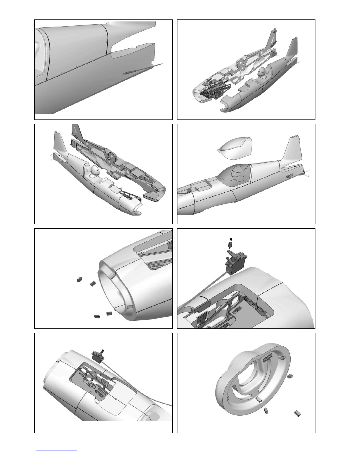
Seite 27
pic. 15 pic. 16
pic. 13
pic. 17
pic. 11
pic. 14
pic. 12
pic. 18
26
58
58
54
55
56
58
Page 28
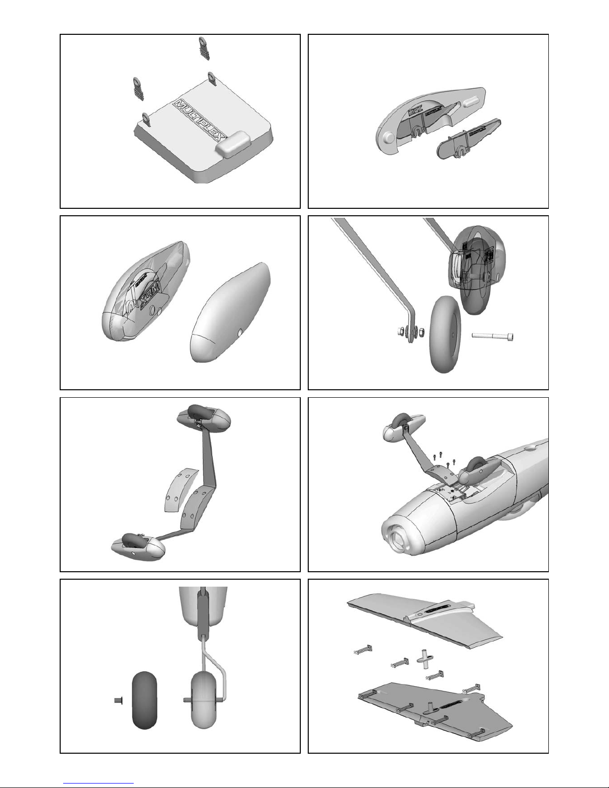
Seite 28
pic. 23 pic. 24
pic. 21
pic. 25
pic. 19
pic. 22
pic. 20
pic. 26
68
65
63
58
62
19
10
45
32
18
65
67
22
44
12
38
13
70
71+55
Page 29

Seite 29
pic. 31 pic. 32
pic. 29
pic. 33
pic. 27
pic. 30
pic. 28
pic. 34
72
15
14
49
43
16
43
17
48
42
53+55
53+55
41
Page 30

Seite 30
pic. 39 pic. 40
pic. 37
pic. 41
pic. 35
pic. 38
pic. 36
pic. 42
23
24
36
10
77
36
85
84
83
82
818065
61
36
78
30
29
77
50
79
37
36
9
50
49
35
86+87
35
25
11
8
53+55
75
Page 31

Seite 31
pic. 47
pic. 45
pic. 43
pic. 46
pic. 44
100mm
51+55
75
51+55
Page 32

Seite 32
Montez la roulette arrière 70 sur le train arrière et maintenez-la en position avec la bague d’arrêt 71.
Vue 25
3. Empennage (KIT+RR)
Collez dans le plan fi xe inférieur du stabilisateur 13 quatre
supports de charnière 44. Collez entre les supports de char-
nière, la douille de fi xation 38 du stabilisateur. Collez ensuite
la partie inférieure du plan fi xe sur sa partie supérieure 12.
Vue 26
Collez les axes de charnière 43 dans la gouverne de profon-
deur 14. Collez le tube carbone 72 (Ø 3mm) dans la longue
rainure. Refermez la gouverne de profondeur en collant le
cache 15 et le guignol 49.
Vue 27
La gouverne de profondeur peut maintenant être clipsée
sur le plan fi xe et l’ensemble monté dans le dégagement du
fuselage. Le stabilisateur complet sera fi xé, par le dessous,
avec une vis plastique 48 (M5x60).
Vues 28 + 29
Montez un raccord de tringle 53 sur le guignol et faites
passer la tringle de commande (corde à piano) à travers le
perçage du raccord et fi xez-la, lorsque la gouverne est au
neutre, avec une vis sans tête M3 55.
Vue 30
Collez également deux axes de charnière dans le volet de
direction 16 ainsi que le guignol de commande 42 de la
direction. Le volet de direction peut maintenant également
être clipsé sur la dérive mais fi xez d’abord la commande
de la direction sur l’extrémité inférieure du volet avant de
clipser le volet de direction sur la dérive.
Vues 31 – 33
Comme sur la gouverne de profondeur, montez un raccord
de tringle 53 et fi xez la corde à piano avec une vis sans
tête M3 55.
Vue 34
4. Montage du moteur (KIT+RR)
Fixez le moteur avec les quatre vis fournies sur le couple
moteur en alu 59. Mettez une goutte de frein-fi lets sur toutes
les vis (résistance moyenne)! Fixez le moteur sur le fuselage
à l’aide des entretoises 61, des quatre vis 60 (M4x65) et
avec les rondelle U 65.
Vue 35
Sur l’arbre du moteur, montez maintenant la pièce d’entraînement 86 de l’hélice avec le cône de serrage 87, la fl asque
du cône 85, l’hélice 84, une rondelle U 83 (int. Ø 6mm) et
l’écrou M6 82. Serrez légèrement l’écrou et mettez l’hélice
en butée sur les tétons du fl asque du cône. Maintenez
l’hélice dans cette position quand vous serrez défi nitive-
ment l’écrou.
Pour conclure, montez le cône 81 et fi xez-le sur la fl asque
avec deux vis 81 (3x16mm).
Vue 36
5. Montage des ailes (KIT+RR)
Montez tout d’abord le baldaquin pour l’aile supérieure.
Pour cela, collez sur l’entretoise centrale 25 du baldaquin
les fl ancs de baldaquin 23 et 24 ainsi que la douille de
fi xation de l’aile 35. Sur le dessous de cet ensemble, collez
respectivement les pièces d’arrêt gauche et droite 29 et 30
puis la baguette CFK 78 (3x1x100mm).
Vue 37
Dans les deux haubans des ailes 10 et 11, collez en haut
et en bas respectivement un clip de fi xation des haubans
36 et au dos, une baguette CFK 77 (3x1x190mm). Veillez
à ce que la colle ne s’infi ltre pas dans le Clip.
Vues 38 + 39
Collez dans l’aile supérieure 8 le longeron tube 79 et de
chaque coté collez un réceptacle pour les clips de haubans
37. Sur les ailerons, il y a des dégagements destinés à
recevoir les cardans de liaison 50 des ailerons. Collez-les
également de part et d’autre de l’aile.
Vue 40
Avec votre émetteur, mettez les servos de commande des
ailerons au neutre et montez les palonniers des servos.
Collez les servos dans leur logement de l’aile inférieure 9.
Pour cela, mettez un peu de colle avec le pistolet à colle au
niveau des pattes de fi xation du servo. Les cordons servo
sont placé dans la rainure et recouverts par une bande de
ruban adhésif (Tesa). Par ailleurs, collez sur chaque aileron un guignol 49 et un support pour cardan de liaison 50
des ailerons. Dans le perçage de la partie centrale de l’aile
collez la douille 35 pour la fi xation de l’aile.
Vue 41
Fixez respectivement une tringle 75 sur les palonniers des
servos de commande des ailerons et reliez-les aux guignols,
comme d’habitude maintenant, aux raccords de tringle 53
et aux guignols avec une vis sans tête M3 55.
Vue 42
Collez soigneusement le baldaquin monté sur l’aile supérieure (Attention à son positionnement!).
Vue 43
6. Montage de l’ensemble de réception (KIT+RR)
Branchez tous les cordons servos sur le récepteur et
programmez le modèle en fonction des débattements
recommandés. Chez MULTIPLEX, les sorties récepteurs
sont attribuées de la manière suivante (si elles ne sont pas
attribuées librement par ailleurs):
1. Aileron gauche
2. Profondeur
3. Direction
4. Gaz (moteur)
5. Aileron droit
Fixez le récepteur avec de la bande Velcro sur le dessous du M-Frame. Pour une meilleure adhérence de
la bande sur le bois nous vous conseillons d’y mettre
quelques gouttes de colle Zacki. Vous pouvez ensuite
encore fi xer le récepteur avec un collier de serrage.
Page 33

Seite 33
7. Montage • nal du modèle (KIT+RR)
Montez d’abord l’aile inférieure sur le fuselage. Retournez
le fuselage et positionnez l’aile par son bord d’attaque entre
le train d’atterrissage et les carénages de roue. Branchez
maintenant les cordons servos des ailerons sur le récepteur.
Rabattez ensuite le bord de fuite sur le fuselage et logez la
patte dans le fuselage. L’aile peut maintenant être plaquée
défi nitivement et vissée avec une vis plastique 47 (M5x35)
sur le fuselage.
Remettez le modèle sur son train d’atterrissage et clipsez
les haubans gauche et droit sur l’aile inférieure. Montez
maintenant l’aile supérieure avec son baldaquin sur le
fuselage et clipsez également les haubans dans l’aile supérieure. Fixez ensuite cette aile sur le fuselage avec une vis
plastique 47 (M5x35).
Vue 44
Deux tringles métalliques 76 relient les deux ailerons. Mon-
tez d’abord des raccords sur tous les supports. Pour cela,
utilisez les pièces rouges 51 pour la gauche et les pièces
vertes 52 pour le coté droit.
Mettez les ailerons au neutre et fi xez d’abord la tringle en
haut avec une vis sans tête M3 55. Lorsque les deux ailerons sont au neutre, fi xez également la tringle de liaison en
bas avec une vis sans tête M3 55.
Procédez de la même manière de l’autre coté!
Vues 45 + 46
Pour le démontage du modèle, il suffi t de déclipser les
raccords de leur support. Les ailerons resteront ainsi réglés
entre eux. Grâce aux couleurs, vous verrez tout de suite de
quel coté cela se monte:
ROUGE = gauche
VERT = droite
8. Centrage (KIT+RR)
Collez dans un premier temps les deux poids de centrage
91 dans le compartiment moteur, de manière à ce que le
capot moteur puisse encore se monter.
Positionnez l’accu sur sa rampe de fi xation de manière à
ce que le centre de gravité se situe à 100 mm (mesuré
à partir du bord d’attaque de l’aile supérieure, près du
fuselage). Fixez l’accu avec les bandes Velcro 88 et 89 et
avec le collier Velcro 90.
Pour une adhérence correcte de la bande dans le fond du
fuselage, nous vous conseillons d’y mettre quelques gouttes
de colle Zacki.
9. Débattements recommandés des gouvernes
Pour un programme de voltige classique:
Direction: droite/gauche: 40 mm, 60% EXPO
Profondeur: haut 40 mm, bas 40 mm, 70%
EXPO
Ailerons: haut 17 mm bas 17 mm, 40%
EXPO
Mixage (linéaire): 3,5mm ailerons opposés à la
direction
àCela signifi e: lorsque la direction
est complètement à droite, l’aileron
est entraîne de 3,5mm vers la
gauche
4mm profundeur à la direction
àCela signifi e: lorsque la direction
est complètement à droite/ sur la
gauche, le profundeur entraîne de
4mm en haut.
Pour la voltige 3D:
Direction: droite/gauche: 65 mm, 60% EXPO
Profondeur: haut 55 mm, bas 55 mm, 70%
EXPO
Ailerons: haut 22 mm / bas 22 mm, 50%
EXPO
Mixage (linéaire): 3,5mm ailerons opposés à la
direction
àCela signifi e: lorsque la direction
est complètement à droite, l’aileron
est entraîne de 3,5mm vers la
gauche
4mm profundeur à la direction
àCela signifi e: lorsque la direction
est complètement à droite/ sur la
gauche, le profundeur entraîne de
4mm en haut.
Page 34

Seite 34
Liste de pièces KIT ROCKSTAR # 214278 & RR ROCKSTAR # 26 4278:
Rep. Kit RR Désignation Matériau Dimensions
1 1 1 Notice de montage KIT Papier 80g/m² DIN-A4
2 1 1 Fiche de réclamation Papier 80g/m² DIN-A4
3 1 1 Planche de décoration Imprimé autocollant 700 x 1000mm
4 1 1 Demi-fl anc gauche fuselage Mousse Elapor Pièce terminée
5 1 1 Demi-fl anc droitfuselage Mousse Elapor Pièce terminée
6 1 1 Capot moteur Mousse Elapor Pièce terminée
7 1 1 Dessus du fuselage Mousse Elapor Pièce terminée
8 1 1 Aile supérieure Mousse Elapor Pièce terminée
9 1 1 Aile inférieure Mousse Elapor Pièce terminée
10 1 1 Hauban aile gauche Mousse Elapor Pièce terminée
11 1 1 Hauban aile droite Mousse Elapor Pièce terminée
12 1 1 Plan fi xe supérieur Mousse Elapor Pièce terminée
13 1 1 Plan fi xe inférieur Mousse Elapor Pièce terminée
14 1 1 Gouverne de profondeur Mousse Elapor Pièce terminée
15 1 1 Cache gouverne de profondeur, Mousse Elapor Pièce terminée
16 1 1 Volet de direction Mousse Elapor Pièce terminée
17 1 1 Cache volet de direction Mousse Elapor Pièce terminée
18 1 1 Carénage intérieur gauche Mousse Elapor Pièce terminée
19 1 1 Carénage extérieur gauche Mousse Elapor Pièce terminée
20 1 1 Carénage intérieur droit Mousse Elapor Pièce terminée
21 1 1 Carénage extérieur droit Mousse Elapor Pièce terminée
22 1 1 Cache train d‘atterrissage Mousse Elapor Pièce terminée
23 1 1 Baldaquin gauche Mousse Elapor Pièce terminée
24 1 1 Baldaquin droit Mousse Elapor Pièce terminée
25 1 1 Entretoise baldaquin Mousse Elapor Pièce terminée
26 1 1 Verrière Pièce plastique moulée Pièce terminée
27 1 1 M- Frame Fixation complète moteur CTP tilleul 3mm Pièce terminée
28 4 4 Contre-plaque Baldaquin CTP tilleul 3mm Pièce terminée
29 1 1 Arrêt gauche Baldaquin plastique moulée par injection Pièce terminée
30 1 1 Arrêt droit Baldaquin plastique moulée par injection Pièce terminée
31 2 2 Bride de verrouillage plastique moulée par injection Pièce terminée
32 2 2 Clip de fi xation plastique moulée par injection Pièce terminée
33 2 2 Plaque fi xation A aile plastique moulée par injection Pièce terminée M5
34 2 2 Plaque fi xation B aile plastique moulée par injection Pièce terminée M5
35 2 2 Douille de fi xation aile plastique moulée par injection Pièce terminée
36 4 4 Clip de fi xation du hauban plastique moulée par injection Pièce terminée
37 4 4 Support clip fi xation hauban plastique moulée par injection Pièce terminée
38 1 1 Douille de fi xation stabilisateur, plastique moulée par injection Pièce terminée
39 1 1 Support écrou (M5) plastique moulée par injection Pièce terminée
40 1 1 Support roulette arrière plastique moulée par injection Pièce terminée
41 1 1 Pièce de serrage support roulette arrière, plastique moulée par injection
42 1 1 Guignol volet de direction plastique moulée par injection Pièce terminée
43 6 6 Axe charnière plastique moulée par injection Pièce terminée
44 6 6 Support axe charnière plastique moulée par injection Pièce terminée
45 1 1 Support gauche carénage plastique moulée par injection Pièce terminée
46 1 1 Support droit carénage plastique moulée par injection Pièce terminée
47 2 2 Vis plastique tête cylindrique Plastique M5 x 35mm
48 1 1 Vis plastique tête cylindrique Polyamide M5 x 60mm
Page 35

Seite 35
Rep. Kit RR Désignation Matériau Dimensions
49 3 3 Guignol „Twin“ plastique moulée par injection, Pièce terminée
50 4 4 Support cardan - liaison ailerons, plastique moulée par injection, Pièce terminée
51 2 2 Cardan ROUGE Métal Pièce terminée Ø6 x 8mm
52 2 2 Cardan VERT Métal Pièce terminée Ø6 x 8mm
53 4 4 Cardan CLAIR Métal Pièce terminée Ø6 x 8mm
54 2 2 Raccord de tringle CLAIR Métal Pièce terminée Ø6 x 8mm
55 11 11 Vis sans tête CHc Métal M3 x 3mm
56 2 2 Ecrou freiné Métal M2
57 1 1 Ecrou freiné Métal M5
58 8 8 Aimant Neodyne 5x2x10mm
59 1 1 Support moteur Alu Alu Pièce terminée
60 4 4 Vis CHc fi xation support moteur, Métal M4 x 65mm
61 4 4 Entretoise couple moteur Alu Pièce terminée
62 1 1 Train d‘atterrissage Alu Pièce terminée
63 2 2 Ecrou freiné Métal M4
64 2 2 Vis axe de roue Métal M4 x 40mm
65 8 8 Rondelle U Métal innen Ø 4mm
66 2 2 Ecrou fi xation axe de roue Métal M4
67 2 2 Roue Plastique Ø73mm
68 4 4 Vis CHc Métal M4 x 12mm
69 1 1 Train de roulette arrière Corde à piano Ø1,5 x 210mm
70 1 1 Roulette arrière légère en mousse, Mousse caoutchouc, Ø26 mm
71 1 1 Bague d‘arrêt roulette arrière Métal int. Ø 2mm
72 1 1 Tube CFK Ø3 Carbone Ø3 x 370mm
73 2 2 Corde à piano Métal Ø1,2 x 740mm
74 2 2 Gaines Plastique Ø3 x 590mm
75 2 2 Tringle de cde ailerons avec extrémité en Z, Métal Ø1,3 x 70mm
76 2 2 Liaison aileron Métal Ø1,5 x 210mm
77 2 2 Renfort ailes baguette CFK CFK 3 ,0 x 1,0 x 190
78 1 1 Renfort central CFK CFK 3,0 x 1,0 x 100
79 1 1 Fourreau Tube GFK Ø8 x 800mm
80 2 2 Vis de fi xation cône Métal 3x16mm
81 1 1 Cône plastique moulée par injection, Ø62mm
82 1 1 Ecrou Métal M6
83 1 1 Rondelle U Métal à l‘intérieur Ø 6mm
84 1 1 Hélice plastique moulée par injection, 14x7“
85 1 1 Flasque cône plastique moulée par injection, Ø62mm
86 1 1 Pièce d‘entrainement hélice Métal Pièce terminée
87 1 1 Cône de serrage Métal Pièce terminée
88 3 3 Velcro coté crochets Synthétique 25 x 60 mm
89 3 3 Velcro coté Velours Synthétique 25 x 60 mm
90 1 1 Collier Velcro Synthétique 25x 200 mm
91 2 2 Poids de centrage Métal 25 x 19x 5 mm
92 0 4 Motor mount screws Metal 3 x 8mm
93 0 1 Motor Himax 4220-620
94 0 4 Servos HiTec HS-82MG
95 0 1 ESC MULTIcont BL-60 SD
Page 36

Seite 36
Sicurezza per gli aeromodelli MULTIPLEX
Il modello NON È UN GIOCATTOLO nel senso comune del termine.
Con la messa in funzione del modello l’utente dichiara di conoscere e aver capito il contenuto delle istruzioni per l’uso,
in particolare le avvertenze sulla sicurezza, gli interventi di manutenzione, le limitazioni di funzionamento e i vizi.
Questo modello non deve essere messo in funzione da bambini di età inferiore ai 14 anni. Se minorenni utilizzano il
modello sotto la sorveglianza di un adulto con obbligo di assistenza secondo la legge ed esperto, quest’ultimo è responsabile affi nche le avvertenze delle ISTRUZIONI PER L’USO vengano rispettate.
IL MODELLO E I RELATIVI ACCESSORI DEVONO ESSERE TENUTI LONTANI DAI BAMBINI DI ETÀ INFERIORE AI 3
ANNI! LE MINUTERIE RIMOVIBILI DEL MODELLO POSSONO ESSERE INGOIATE DA BAMBINI DI ETÀ INFERIORE
AI 3 ANNI. PERICOLO DI ASFISSIA!
Durante il funzionamento del modello si devono osservare tutte le avvertenze delle ISTRUZIONI PER L’USO. La Multiplex Modellsport GmbH & Co. KG non è responsabile per perdite e danni di qualunque tipo che si vengono a creare
come conseguenza di utilizzo sbagliato o abuso di questi prodotti, compresi i relativi accessori. Ciò comprende perdite
e danni diretti, indiretti, voluti e involontari e ogni forma di danni successivi.
Ogni avvertenza di sicurezza di queste istruzioni deve essere assolutamente rispettata e contribuisce ad un utilizzo
sicuro del vostro modello. Utilizzate il vostro modello con intelligenza ed attenzione, e sarà un bel divertimento per voi e
per gli spettatori, senza rappresentare alcun pericolo. Se non utilizzate il vostro modello responsabilmente, si potranno
verifi care notevoli danni materiali e lesioni gravi. Voi soli siete responsabili che le istruzioni per l’uso vengano rispettate
e che le avvertenze sulla sicurezza vengano applicate.
Impiego conforme alla destinazione d’uso
Il modello può essere utilizzato solo in campo hobbistico. Ogni altro tipo di utilizzo è proibito. Per i danni o gli infortuni
di ogni tipo a persone e animali risultanti da un utilizzo improprio è responsabile esclusivamente l’utente del modello e
non il costruttore.
Per l’uso del modello è permesso utilizzare solo gli accessori da noi consigliati. I componenti consigliati sono già collaudati
e adattati al modello ai fi ni di un funzionamento sicuro. Se si utilizzano altri componenti o se il modello viene modifi cato,
vengono a mancare tutti i diritti di garanzia del costruttore e/o rivenditore.
Per mantenere basso il rischio durante il funzionamento del modello, osservare i seguenti punti:
l Il modello viene comandato tramite radiocomando. Nessun radiocomando è protetto da radiodisturbi. Tali disturbi
possono causare la perdita di controllo temporanea sul modello. Per questo motivo durante il funzionamento del
vostro modello per evitare collisioni bisogna sempre rispettare grandi distanze di sicurezza in tutte le direzioni.
Già al primo avvisaglio di radiodisturbi dovete smettere di utilizzare il vostro modello!
l Dovete mettere in funzione il vostro modello solo dopo aver eseguito con successo un completo test di funzio-
namento e un test della ricezione, secondo le istruzione del vostro radiocomando.
l Il modello deve essere messo in volo solo a condizioni di visibilità buone. Non volare in direzione del sole per
non essere abbagliati o a condizioni di visibilità cattive.
l Un modello non deve essere messo in funzione sotto l’infl usso dell’alcool o di sostanze stupefacenti o medicinali
che limitano la capacità di reazione.
l Fare volare il modello solo se le condizioni atmosferiche e il vento vi permettono di controllarlo bene. Anche a
vento debole tenere conto che intorno ad oggetti si formano vortici che possono infl uenzare il modello.
l Non far volare mai il modello in luoghi in cui potete mettere in pericolo voi stessi o altri, come p.es. in centri
abitati, su elettrodotti, strade o binari.
l Non guidare mai il modello verso persone né animali. Volare a raso sulla testa di altre persone non è un segno
di particolare bravura, ma espone gli altri ad un rischio inutile. Nell’interesse di tutti segnalare questo fatto anche
agli altri piloti. Fate volare il modello sempre in modo che né voi né gli altri siano in pericolo. Pensare sempre
che anche il miglior radiocomando può in ogni momento essere disturbato. Anche una pratica di volo di lunghi
anni, priva di incidenti non è una garanzia per il prossimo minuto di volo.
I
Page 37

Seite 37
Rischi residui
Anche se il modello viene messo in funzione secondo le norme e tenendo conto di tutti gli aspetti di sicurezza, sussiste
sempre un determinato rischio residuo.
Quindi è obbligatorio stipulare un’assicurazione di responsabilità civile. Nel caso foste socio di un’associazione o
federazione, potete stipulare l’assicurazione anche in questa istituzione. Fare attenzione ad avere una protezione assicurativa suffi ciente (aeromodello con motorizzazione). Mantenere i modelli e il radiocomando sempre in perfetto stato.
I seguenti pericoli possono verifi carsi in relazione alla costruzione e all’esecuzione del modello:
l Lesioni dovute all’elica: appena il pacco batteria è collegato, tenere libera la zona dell’elica. Osservare anche che
gli oggetti di fronte all’elica possono essere aspirati o che gli oggetti dietro possono essere spinti via. Il modello
si può mettere in moto. Quindi orientarlo sempre in modo che nel caso di un avvio involontario del motore non si
possa muovere in direzione di altre persone. Durante le regolazioni in cui il motore è in funzione o può mettersi
in funzione, il modello deve sempre essere tenuto da un aiutante.
l Precipitazione dovuto ad errore di comando: Può succedere anche al miglior pilota, quindi far volare il modello
solo in ambiente sicuro: un terreno omologato per aeromodelli è una relativa sicurezza sono indispensabili.
l Precipitazione dovuta ad errore tecnico o danni dovuti al trasporto o danni precedenti non conosciuti. È obbli-
gatorio controllare attentamente il modello prima di ogni messa in volo. Ma bisogna sempre tenere conto che si
può verifi care un guasto del materiale. Non fare mai volare il modello in luoghi in cui si possono causare lesioni
agli altri.
l Rispettare i limiti di funzionamento. Un volo estremamente duro indebolisce la struttura e può o comportare un
guasto improvviso del materiale, o la precipitazione del modello durante voli successivi dovuta a danni successivi „latenti“.
l Pericolo d’incendio dovuto a malfunzionamento dell’elettronica. Conservare i pacchi batteria in modo sicuro, ris-
pettare le avvertenze di sicurezza dei componenti elettronici nel modello, del pacco batteria e del caricabatteria,
proteggere l’elettronica dall’acqua. Fare attenzione che il regolatore e il pacco batteria siano suffi cientemente
raffreddati.
Le istruzioni dei nostri prodotti non devono essere riprodotte e /o pubblicate senza espressa autorizzazione
della Multiplex Modellsport GmbH & Co. KG (per iscritto) - neanche solo in parte né sotto forma di stampa né
in formato elettronico.
I
Page 38

Seite 38
Familiarizzate con il contenuto della scatola di montaggio!
Le scatole di montaggio per modelli della MULTIPLEX vengono sottoposte costantemente a controlli del materiale durante la produzione. Speriamo che siate soddisfatti del contenuto della scatola di montaggio. Vi preghiamo tuttavia, di
controllare tutte le parti (consultando la lista materiale) prima dell’utilizzo, visto che le parti già lavorate non potranno
essere sostituite. Se una parte dovesse essere difettosa, saremo anche disposti, dopo averla controllata, a ripararla
e sostituirla. Vi preghiamo di inviare la parte in questione al nostro reparto modellismo allegando assolutamente lo
scontrino fi scale e la comunicazione di reclamo debitamente compilata (formulario). Ci adoperiamo di continuo ai fi ni
del perfezionamento tecnico dei nostri modelli. Con la riserva di apportare in ogni momento modifi che al contenuto della
scatola di montaggio, in forma, dimensioni, tecnica, materiali ed accessori senza preavviso. Si prega di avere comprensione per il fatto che dalle informazioni né dalle illustrazioni di queste istruzioni sussiste alcun diritto
Importante!
Modelli radiocomandati e soprattutto gli aeromodelli non sono giocattoli nel comune senso del termine. La loro
costruzione e il loro funzionamento richiedono conoscenze tecniche, un minimo ad accuratezza manuale e disciplina e consapevolezza dei rischi. Errori e imprecisioni durante la costruzione ed il funzionamento possono
causare lesioni alle persone e danni materiali. Visto che il costruttore non ha alcuna infl uenza su un assemblaggio,
una manutenzione e un funzionamento corretti, vogliamo espressamente porre l’attenzione su questi pericoli.
Avvertenza:
Il modello ha come ogni aereo, dei limiti dal punto di vista statico! Voli in picchiata e altre manovre rischiose senza pensarci possono comportare la perdita del modello. Osservare quanto segue: in tali casi non forniamo alcuna sostituzione.
Avvicinarsi con attenzione ai limiti. Il modello è previsto per la motorizzazione da noi consigliata, ma può resistere perfettamente e senza danni ai carichi solo se assemblato in modo perfetto.
Accessori necessari per il modello ROCKSTAR:
Zacki ELAPOR 20g VE1 RR+KIT Art.nr. 852727
Li-BATT FX 4/1 2600 (M6) RR+KIT Art.nr. 157362
Ricevente RX-5 light M-LINK 2,4 GHz RR+KIT Art.nr. 55808
Set motorizzazione ROCKSTAR KIT Art.nr. 332667
Servo HS-82 MG (4x) KIT Art.nr. 112088
Prolunga 15 cm (UNI) (2x) KIT Art.nr. 85019
I
Page 39

Seite 39
Nota importante
Questo modello non è in Styropor ™! Pertanto non è possibile incollare con colla vinilica, poliuretano o colla epoxy.
Queste colle aderiscono solo superfi cialmente e non tengono in caso di emergenza. Utilizzare unicamente colla istanta-
nea in cianoacrilato a viscosità media, preferibilmente Zacki ELAPOR® # 59 2727, perfezionata e adattata all’espanso
ELAPOR®. Se utilizzate i prodotti Zacki-ELAPOR® potete rinunciare per lo più all’uso di kicker e attivatore. Se invece
utilizzate altre colle, e non potete rinunciare a kicker/attivatore, spruzzare questi prodotti esclusivamente all’aperto, per
ragioni di salute. Attenzione durante il lavoro con tutte le colle in cianoacrilato. Queste colle induriscono nel giro di pochi
secondi, per cui va evitato il contatto con le dita o altre parti del corpo. Per proteggere gli occhi portare assolutamente
occhiali protettivi! Tenere lontano dalla portata dei bambini! In alcuni punti è anche possibile utilizzare colla a caldo. Nelle
istruzioni, se necessario, lo indichiamo!
Come lavorare con Zacki ELAPOR®
Zacki ELAPOR® è stata sviuppata appositamente per incollare i nostri modelli in schiuma ELAPOR® .
Per effettuare l’incollaggio in modo ottimale, bisogna osservare i seguenti punti:
• Evitare l’utilizzo di attivatore. L’attivatore rende il collegamento nettamente più debole.
Soprattutto nel caso di incollaggi di grandi superfi ci consigliamo di far essiccare i componenti per 24 h.
• L’attivatore è da utilizzarsi esclusivamente per il fi ssaggio a punti. Spruzzare solo poco attivatore su un lato.
Lasciar seccare l’attivatore per ca. 30 secondi.
• Per un incollaggio ottimale irruvidire la superfi cie con carta abrasiva (grana da 320).
Curvo - non esiste. Nel caso qualcosa venisse piegato p.es. durante il trasporto, lo si può riparare. In questo caso
ELAPOR® è simile al metallo. Ricomporre qualcosa di piegato, il materiale è leggermente elastico ma mantiene
la forma. Tutto ha però dei limiti - non esagerate!
Curvo - si che esiste! Se volete verniciare il Vostro modello, sfregare leggermente la superfi cie con MPX Primer #
602700 come se voleste pulire il modello. Gli strati di vernice non devono essere in alcun caso troppo grossi o ir-
regolari , altrimenti il modello si deforma. Diventa curvo, pesante e spesso perfi no inutilizzabile! Vernici opache danno
spesso il miglior risultato estetico.
Dati tecnici ROCKSTAR:
Apertura alare: 1050 mm
Lunghezza complessiva: 1060 mm
Peso in ordine di volo: 1800 g
Superfi cie alare: 48 dm²
Carico alare: 38 g/dm²
Comandi: 4
Funzioni RC: elevatore, timone di direzione, alettoni, motore
durata di volo: ca. 7 min (4S ~2600 mAh)
Nota: Per una più facile consultazione, staccate dal centro le pagine con i disegni!
Page 40

Seite 40
Congratulazioni per il vostro nuovo Multiplex ROCKSTAR.
Per costruire il modello avete bisogno dei seguenti
utensili:
2x Zacki-Elapor # 85 2727 (KIT) (1xRR)
1x UHU Por (KIT)
pistola termoadesiva (KIT)
cacciavite con punta a croce medio (KIT)
cacciavite a testa piatta medio (KIT)
cutter (KIT)
pinza appuntita (KIT)
chiave a brugola da 1,5 (KIT)
chiave a brugola da 3 (KIT)
chiave a bocca da 10 (KIT)
punta da 2,5mm v
Prima del montaggio:
controllare se i componenti forniti sono completi in base alla
lista materiale a pagina 43&44 (pic.01 &02).
1. Assemblaggio della fusoliera (KIT)
Clippare tra di loro ambedue i componenti del controsupporto alare 33 e 34 e incollarli con Zacki! ! Importante ! Durante
l’incollaggio/clippaggio dei componenti può fuoriuscire della
colla. Incollare quindi i ganci di chiusura Canopylock 31, il
controsupporto del baldacchino 28 e il controsupporto dell’a-
la nel semiguscio destro della fusoliera 5. Incollare ambedue
i supporti asse a cerniera 44 nelle fessure della metà destra
dell’impennaggio elevatore. Incollare anche il supporto del
dado 39 (M5) nel supporto del ruotino di coda 40.
Figg. 03 + 04
Inserire un tondino a F 73 attraverso la guaina bowden 74
e posarlo nel semiguscio destro della fusoliera in modo che
la guaina bowden esca dalla fusoliera da dietro e sporga di
ca. 30mm, incollarlo bene.
Figg. 05 – 07
Incollare con Zacki il M-Frame già premontato 27 nel semiguscio destro della fusoliera 5.
Fig. 08
Nel semiguscio sinistro della fusoliera 4 incollare in modo
analogo ai passi precedenti i ganci di chiusura Canopylock
31 e il controsupporto del baldacchino 28. Successivamente
anche qui una guaina bowden 74 con un tondino a F 73
inserito, viene posata in modo che la guaina sporga alla
fi ne fi ne della fusoliera di ca. 30mm.
Figg. 09 – 11
Inserire tra di loro quindi i due semigusci della fusoliera
SENZA colla e controllare che la sede dei componenti sia
corretta. Se tutto è ben posizionato, applicare la colla e
unire i componenti in modo esatto.
Figg. 12 + 13
Dopo questo passo si può colorare a piacere la vostra
fi gura pilota.
Fare attenzione che le superfi ci scure sotto la capottina
cabina possono riscaldarsi se esposte alla radiazioni solari. In questi punti ELAPOR, a seconda delle circostanze,
potrebbe spaccarsi/potrebbero formarsi bolle!
Incollare l’adesivo cruscotto (decal) sul relativo pannello nel
cockpit. Quando si è soddisfatti dell’allestimento del cockpit,
incollare la capottina cabina 26 con UHU Por sulla fusoliera.
Fig. 14
Per fi ssare il cupolino motore 6 incollare le quattro calamite
58 nelle loro apposite posizioni.
Fig. 15
Prendere in mano il servo del direzionale e metterlo in posizione neutra con il radiocomando. Praticare i fori esterni
della leva del servo su un Ø di 2,5mm. Inserire la leva del
servo secondo la fi g. 16 e assicurarla con la vite per servi
a corredo. Montare alla leva del servo il collegamento rinvii
54 con un dado di arresto M2 56 nel foro esterno. Avvitare
in alto nel collegamento rinvii un grano M3 55.
Quindi inserire il servo nella cavità sinistra del M-Frame e
fi ssarlo con le viti a corredo.
Fig. 16
Con il servo del timone di quota procedere in modo analogo
ma in questo caso la leva del servo viene inserita girata
di 180°. Montare il servo del timone di quota nella cavità
destra del M-Frame.
Fig. 17
Incollare nel cupolino motore 6 le altre quattro calamite 58
nelle loro apposite posizioni.
!IMPORTANTE! Assicurarsi che nessuna coppia di calamite
si respinga in un secondo momento!
Fig. 18
Incollare nel coperchio della fusoliera 7 ambedue i perni
Canopylock 32 nelle fessure.
Fig. 19
2. Assemblaggio del carrello (KIT+RR)
Incollare nell’interno sinistro della metà del rivestimento sinistro della ruota 18 il supporto sinistro del rivestimento della
ruota 45. Incollare successivamente la metà esterna del
rivestimento della ruota 19. Con il rivestimento destro della
ruota procedere in modo analogo (componenti 20, 46, 21).
Figg. 20 + 21
Inserire la ruota leggera 67 nel rivestimento sinistro della
ruota e inserire quindi la vite 64 (M4x40) come asse della
ruota attraverso il rivestimento della ruota e la ruota. Quindi
avvitare leggermente un dado M4 66 sulla vite. Inserire
la vite con una rondella a U 65 attraverso il foro al piede
sinistro della staffa del carrello 62 e fi ssarla con rondelle a
U 65 e dado di fermo M4 63.
IMPORTANTE: “davanti” alla staffa del carrello si trova il lato
diritto! La fi gura 47 rende chiaro ancora una volta lo schema del montaggio. In modo analogo viene montato anche
il ceppo del freno destro della ruota alla staffa del carrello.
Fig. 22
Incollare con una goccia di Zacki la copertura del carrello
22.sulla staffa del carrello. Prima dell’incollaggio si prega
di controllare l’allineamento del componente, tenendolo
alla fusoliera. Avvitare quindi il carrello assemblato con le
quattro viti a esagono cavo (M4x12) alla fusoliera.
Figg. 23 + 24
Page 41

Seite 41
Spostare il ruotino di coda 70 sulla staffa del ruotino di coda
e assicurarlo con l’anello di regolazione 71.
Figg. 25
3. Piani di coda (KIT+RR)
Incollare alla metà inferiore dell’impennaggio elevatore
13 quattro alloggiamenti assi a cerniera 44. Tra gli alloggiamenti interni assi a cerniera incollare la boccola per il
fi ssaggio del piano di coda 38. Incollare successivamente
la metà inferiore con la metà superiore del piano di coda 12.
Fig. 26
Incollare gli assi nelle cerniere del raccordo concavo 43 nel
timone di quota 14. Incollare il tubo in plastica rinforzata in
fi bra di carbonio 72 (Ø 3mm) nella fessura lunga. Chiudere
il timone di quota incollando il coperchio del timone di coda
15 e la squadretta per timone 49.
Fig. 27
Ora il timone di quota può essere clippato all’impennaggio
elevatore e inserito nella cavità alla fuosoliera. Viene assicurato tramite una vite in plastica 48 (M5x60) dal basso.
Figg. 28 + 29
Montare un collegamento rinvii 53 alla squadretta del timone
e inserire il tondino a F attraverso il foro e assicurarlo al
timone neutro con un grano M3 55.
Fig. 30
Incollare anche al direzionale 16 due assi a cerniera e la
squadretta per timone 42. Chiudere quindi il direzionale
con la copertura del direzionale 17. Il direzionale montato
può quindi essere clippato anch’esso all’impennaggio. A tal
scopo prima appendere il supporto della spina all’estremità
inferiore dell’impennaggio e clippare quindi le cerniere.
Figg. 31 – 33
Montare anche alla squadretta per timone come per il timone di quota un collegamento dei rinvii 53 e fi ssare bene
il tondino a F con il grano M3 55.
Fig. 34
4. Montaggio del motore (KIT+RR)
Fissare il motore con le quattro viti allegate all’ordinata motore 59. Utilizzare tutte le viti con una goccia di frenafi letti
(media resistenza)! Avvitare quindi il motore con l’ausilio
dei perni distanziatori 61 e le quattro viti 60 (M4x65) con
rondelle a U 65 nella fusoliera.
Fig. 35
Poggiare sull’albero del motore il mozzo dell’elica 86 con
il cono di serraggio 87, il piattello dell’ogiva 85, l’elica 84,
e una rondella a U 83 (Ø interno 6mm) e il dado M6 82.
Stringere leggermente il dado e girare l’elica contro gli arresti
sul piattello dell’ogiva. Tenere l’elica in posizione mentre si
stringe completamente il dado.
Poggiare in fi ne il tappo dell’ogiva 81 e avvitarlo con due
viti 81 (3x16mm) al piattello dell’ogiva.
Fig. 36
5. Assemblaggio delle super! ci alari (KIT+RR)
Innanzitutto viene montato il baldacchino per la semiala
superiore. A tal scopo i sostegni del baldacchino 23 e 24 e
la boccola per il fi ssaggio delle ali 35 vengono incollati al
pezzo di connessione baldacchino 25. Nella parte inferiore
del coperchio incollare ogni volta l’arresto destro e quelli
sinistro del baldacchino 29 e 30 dopo anche ancora il listello
in plastica rinforzata in fi bra di carbonio 78 (3x1x100mm).
Fig. 37
Incollare nei due sostegni delle semiali10 e 11 ogni volta in
alto ed in basso un clip per i sostegni 36 e sul retro un listello
in plastica rinforzata in fi bra di carbonio 77 (3x1x190mm).
Fare attenzione che nel clip non vada a fi nire della colla.
Figg. 38 + 39
Nella semiala superiore 8 incollare la baionetta 79 e su
ambedue i lati un supporto per i clip dei sostegni 37. Agli
alettoni si trovano delle cavità per l’alloggiamento dell’elemento di connessione degli alettoni 50. Incollare anch’essi
su ambedue i lati.
Fig. 40
Posizionare i servi degli alettoni tramite il vostro radiocomando in posizione neutra e avvitare le leve servo. Incollare i
servi nella semiala inferiore 9 nella loro apposita posizione.
Utilizzare a tal scopo un po’ di colla a caldo alle linguette
del servo. I cavi sono da posarsi nelle apposite canaline e
incollare con un po’ di scotch. Inoltre incollare negli alettoni
su ambedue i lati ogni volta una squadretta per timone 49
e un supporto per l’elemento di connessione degli alettoni
50. Nella parte della fusoliera poggiata, incollare nel foro
una boccola per fi ssare l’ala 35.
Fig. 41
Appendere nei servi degli alettoni ogni volta un rinvio degli
alettoni 75 e collegarlo in maniera consueta con il collegamento dei rinvii 53 ed un grano M3 55 con la squadretta
per timone.
Fig. 42
Incollare il baldacchino assemblato facendo attenzione
con la semiala superiore (fare attenzione all’allineamento!).
Fig. 43
6. Montaggio dell’impianto di ricezione (KIT+RR)
Inserire tutti i cavi servo nella ricevente e programmare il
modello secondo le escursioni del timone indicate. La disposizione dei connettori presso la MULTIPLEX è la seguente
(per quanto non assegnata liberamente da altri):
1. alettone a sinistra
2. timone di quota
3. direzionale
4. gas
5. alettone a destra
Fissare la ricevente con nastro velcro sul lato inferiore del
M-Frame. Per un collegamento resistente del nastro velcro
al legno consigliamo di aggiungere un paio di gocce di Zacki.
Inoltre la ricevente può essere fi ssata con un serracavo.
Page 42

Seite 42
7. Montaggio • nale dell’aereo (KIT+RR)
Inserire innanzitutto l’ala inferiore nella fusioliera. Girare a
tal scopo la fusoliera sul retro e inserire la semiala con il
bordo di entrata nell’angolo tra il carrello e il rivestimento
della ruota. Quindi collegare il cavo degli alettoni alla ricevente. Piegare quindi il listello fi nale verso la fusoliera
e inserire la linguetta nella fusoliera. Ora la semiala può
essere completamente poggiata e avvitata con una vite di
plastica 47 (M5x35).
Posizionare l’aereo di nuovo sul carrello e clippare i sostegni delle semiali a sinistra e destra alla semiala inferiore.
Inserire ora la semiala superiore con il baldacchino nella
fusoliera e clippare i sostegni della semiala anche in alto.
Infi ne avvitare anche questa semiala con una vite di plastica
47 (M5x35) con la fusoliera.
Fig. 44
Per collegare gli alettorni servono due rinvii in metallo 76.
Montare innanzitutto a tutti i supporti per gli elementi di
connessione degli alettoni i collegamenti dei rinvii. A tal
scopo utilizzare sul lato sinistro componenti rossi 51 e sul
lato destro componenti verdi 52.
Allineare gli alettoni in posizione neutra e fi ssare innanzitutto
in alto un elemento di connessione degli alettoni con un
grano M3 55. Se l’alettone superiore e quello inferiore sono
su neutro, fi ssare l’elemento di connessione degli alettoni
anche in basso con un grano M3.
Procedere analogamente sull’altro lato.
Figg. 45 + 46
Durante lo smontaggio dell’aereo estrarre semplicemente
i collegamenti dei rinvii dai loro supporti. In questo modo
resta invariata la regolazione uniforme degli alettoni tra di
loro. Grazie ai colori dei collegamenti si può riconoscere
subito a che lato appartengono:
ROSSO = sx.
VERDE = dx.
8. Equilibrautra (KIT+RR)
Incollare innanzitutto con Zacki i due pesi di trim 91 nel vano
motore in modo che si possa ancora chiudere il cupolino
motore.
Spostare il pacco batteria della motorizzazione sullo
scivolo del pacco batteria in modo che il baricentro
sia su 100 mm (misurato dallo spigolo superiore della
semila vicino alla fusoliera). Fissare quindi il pacco bat-
teria con i nastri velcro a corredo 88 e 89 e con il passante
in velcro 90.
Per un collegamento resistente del nastro velcro al fondo
della fusoliera consigliamo di aggiungere un paio di gocce
di Zacki.
9. Escursioni dei timoni consigliate
Per un volo acrobatico classico:
Direzionale: a destra/a sinistra 40 mm 60%
EXPO
Elevatore: in alto 40 mm, sotto 40 mm 70%
EXPO
Alettoni: in alto 17 mm sotto 17 mm 50%
EXPO
Mixer(lineare): 3,5mm alettoni opposti al
direzionale
àovvero: con il direzionale
completamente a destra, l’alettone
va a sinistra del 3,5mm
4mm Elevatore a direzinale
àovvero: con il direzionale
completamente a destra / a sinistra,
l’levatore va a sinistra del 4mm
Per volo acrobatico 3D:
Direzionale: a destra/a sinistra 65 mm 60%
EXPO
Elevatore: in alto 55 mm, sotto 55 mm 70%
EXPO
Alettoni: in alto 22 mm sotto 22 mm 50%
EXPO
Mixer(lineare): 3,5mm alettoni opposti al
direzionale
àovvero: con il direzionale
completamente a destra, l’alettone
va a sinistra del 3,5mm
4mm Elevatore a direzinale
àovvero: con il direzionale
completamente a destra / a sinistra,
l’levatore va a sinistra del 4mm
Page 43

Seite 43
Distinta base KIT ROCKSTAR # 21 4278 & RR ROCKSTAR # 2 64278:
Pos. Kit RR Designazione Materiale Dimensioni
1 1 1 KIT Istruzioni per il montaggio Carta 80g/m² DIN-A4
2 1 1 Comunicazione di reclamo modelli, Carta 80g/m² DIN-A4
3 1 1 Decal Foglio adesivo stampato 700 x 1000mm
4 1 1 Semiguscio della fusoliera sx. Elapor espanso Finito
5 1 1 Semiguscio della fusoliera dx. Elapor espanso Finito
6 1 1 Cupolino motore Elapor espanso Finito
7 1 1 Coperchio fusoliera Elapor espanso Finito
8 1 1 Semiala in alto Elapor espanso Finito
9 1 1 Semiala in basso Elapor espanso Finito
10 1 1 Sostegno semiala sx. Elapor espanso Finito
11 1 1 Sostegno semiala dx. Elapor espanso Finito
12 1 1 Piano di quota in alto Elapor espanso Finito
13 1 1 Piano di quota in basso Elapor espanso Finito
14 1 1 Timone di quota Elapor espanso Finito
15 1 1 Coperchio timone di quota Elapor espanso Finito
16 1 1 Direzionale Elapor espanso Finito
17 1 1 Copertura direzionale Elapor espanso Finito
18 1 1 Rivestimento ruota interno a sx., Elapor espanso Finito
19 1 1 Rivestimento ruota esterno a sx., Elapor espanso Finito
20 1 1 Rivestimento ruota interno a dx., Elapor espanso Finito
21 1 1 Rivestimento ruota esterno a dx., Elapor espanso Finito
22 1 1 Copertura carrello Elapor espanso Finito
23 1 1 Baldacchino sx. Elapor espanso Finito
24 1 1 Baldacchino dx. Elapor espanso Finito
25 1 1 Distanziale baldacchino Elapor espanso Finito
26 1 1 Capottina cabina Plastica imbutita Finito
27 1 1 Duomo motore Tornado completo, Compensato tiglio 3mm Finito
28 4 4 Controsupporto baldacchino Compensato tiglio 3mm Finito
29 1 1 Arresto baldacchino sx. Plastica stampata ad iniezione Finito
30 1 1 Arresto baldacchino dx. Plastica stampata ad iniezione Finito
31 2 2 Ganci di chiusura Plastica stampata ad iniezione Finito
32 2 2 Perno di chiusura Plastica stampata ad iniezione Finito
33 2 2 Controsupporto ala A Plastica stampata ad iniezione Finito M5
34 2 2 Controsupporto ala B Plastica stampata ad iniezione Finito M5
35 2 2 Boccola fi ssaggio superfi ci alari, Plastica stampata ad iniezione Finito
36 4 4 Clip sostegno superfi cie alare Plastica stampata ad iniezione Finito
37 4 4 Supporto clip sostegno superfi cie alare, Plastica stampata ad iniezione Finito
38 1 1 Boccola fi ssaggio piano di quota, Plastica stampata ad iniezione Finito
39 1 1 Supporto dado (M5) Plastica stampata ad iniezione Finito
40 1 1 Supporto del ruotino di coda Plastica stampata ad iniezione Finito
41 1 1 Pezzo per bloccaggio appoggio del ruotino di coda, Plastica stampata ad iniezione
42 1 1 Squadretta per timone Plastica stampata ad iniezione Finito
43 6 6 Cerniera raccordo concavo asse, Plastica stampata ad iniezione Finito
44 6 6 Cerniera raccordo concavo supporto asse, Plastica stampata ad iniezione, Finito
45 1 1 Supporto rivestimento ruota sx., Plastica stampata ad iniezione Finito
46 1 1 Supporto rivestimento ruota dx., Plastica stampata ad iniezione Finito
47 2 2 Vite a testa cilindrica plastica Plastica M5 x 35mm
48 1 1 Vite a testa cilindrica plastica Poliammide M5 x 60mm
Page 44

Seite 44
Pos. Kit RR Designazione Materiale Dimensioni
49
3 3 Squadretta per timone „Twin“ Plastica stampata ad iniezione, Finito
50 4 4 Supporto perno cardanico-elemento di connessione degli alettoni
51 2 2 Perno cardanico ROSSO Metallo Finito Ø6 x 8mm
52 2 2 Perno cardanico VERDE Metallo Finito Ø6 x 8mm
53 4 4 Perno caradanico TRASPARENTE, Metallo Finito Ø6 x 8mm
54 2 2 Collegamento rinvii TRASPARENTE, Metallo Finito Ø6 x 8mm
55 11 11 Grano a brugola Metallo M3 x 3mm
56 2 2 Dado di fermo Metallo M2
57 1 1 Dado Metallo M5
58 8 8 Calamita Neodym 5x2x10
59 1 1 Ordinata motore alluminio Alluminio Finito
60 4 4 Vite ad esagono cavo fi ssaggio ordinata motore, Metallo M4 x 65mm
61 4 4 Perno distanziatore ordinata motore, Alluminio Finito
62 1 1 Staffa carrello Alluminio F38 Finito
63 2 2 Dado di fermo Metallo M4
64 2 2 Vite per asse della ruota Metallo M4 x 40mm
65 8 8 Rondella a U Metallo Ø interno 4mm
66 2 2 Dado fi ssaggio asse della ruota, Metallo M4
67 2 2 Ruota leggera Plastica Ø73mm
68 4 4 Vite ad esagono cavo Metallo M4 x 12mm
69 1 1 Staffa ruotino di coda Acciaio a F Ø1,5 x 210mm
70 1 1 Ruota leggera per carrello posteriore, Gomma crepla Ø26 mm
71 1 1 Anello di regolazione per ruotino di coda, Metallo Ø interno 2mm
72 1 1 Tubo in plastica rinforzata in fi bra di carbonio Ø3, Metallo Ø3x370mm
73 2 2 Tondino a F Metallo Ø1,2 x 740mm
74 2 2 Guaine bowden Plastica Ø3 x 590mm
75 2 2 Rinvii alettoni con Z Metallo Ø1,3 x 70mm
76 2 2 Elemento di connessione degli alettoni, Metallo Ø1,5 x 210mm
77 2 2 Listello in plastica rinforzata in fi bra di carbonio sostegno ala, 3 ,0 x 1,0 x 190
78 1 1 Listello in plastica rinforzata in fi bra di carbonio sostegno centrale, 3 x 1 x 100
79 1 1 Baionetta Tubo in vetroresina Ø8x800mm
80 2 2 Viti ogiva Metallo 3x16mm
81 1 1 Testata dell‘ogiva Plastica stampata ad iniezione, fi nito Ø62mm
82 1 1 Dado Metallo M6
83 1 1 Rondella a U Metallo Ø interno 6mm
84 1 1 Elica Plastica stampata ad iniezione 14x7“
85 1 1 Piastra di base ogiva Plastica stampata ad iniezione fi nito Ø62mm
86 1 1 Mozzo elica Metallo Finito
87 1 1 Cono di serraggio Metallo Finito
88 3 3 Nastro velcro parte uncinata Plastica 25 x 60mm
89 3 3 Nastro velcro, parte „stoffa“ Plastica 25 x 60mm
90 1 1 Passante in velcro Plastica 25 x 200mm
91 2 2 Peso trim Metallo 25 x 19 x 5mm
92 0 4 Motor mount screws Metal 3 x 8mm
93 0 1 Motor Himax 4220-620
94 0 4 Servos HiTec HS-82MG
95 0 1 ESC MULTIcont BL-60 SD
Page 45

Seite 45
Cuaderno de seguridad para modelos de aviones MULTIPLEX
El modelo NO ES UN JUGUETE en el sentido habitual de la palabra.
Con la puesta en marcha del modelo, el operador declara que conoce el contenido del manual de instrucciones, especialmente lo respectivo a consejos de seguridad, trabajos de mantenimiento y limitaciones de uso y carencias, pudiendo
cumplir todo lo requerido.
Este modelo no debe ser manejado por menores de 14 años. El manejo del modelo por menores queda supeditado a
ser realizado bajo la supervisión de un adulto que, según la ley, sea responsable y competente, siendo éste responsable
de la aplicación de las advertencias del MANUAL DE INSTRUCCIONES.
¡EL MODELO Y LOS ACCESORIOS CORRESPONDIENTES DEBEN QUEDAR LEJOS DEL ALCANCE DE LOS
MENORES DE 3 AÑOS! ¡LAS PEQUEÑAS PIEZAS SUELTAS DEL MODELO PUEDEN SER TRAGADAS POR LOS
MENORES DE 3 AÑOS! ¡PELIGRO DE ASFIXIA!
Al manejar el modelo deben respetarse todas las advertencias del MANUAL DE INSTRUCCIONES. Multiplex Modellsport
GmbH & Co. KG no será responsable de las pérdidas y daños de cualquier tipo que puedan ocurrir debido a un manejo
erróneo y/o indolente de este producto, incluyendo cualquiera de los accesorios necesarios para su uso. Esto incluye,
de manera directa e indirecta, pérdidas o daños con o sin intención y cualquier tipo de daños a las cosas.
Cada advertencia de seguridad de estas instrucciones debe ser observada forzosamente y contribuyen de manera directa
a un manejo seguro del modelo. Utilice su modelo con juicio y cuidado, y éste le divertirá a Usted y sus espectadores
sin ponerlos en riesgo alguno. Si maneja su modelo de manera poco responsable, éste podría producir serios daños
materiales y provocar graves heridas. Usted será el único responsable de seguir el manual de instrucciones y llevar a
la práctica las advertencias de seguridad.
Uso acorde al contrato
El modelo debe usarse exclusivamente en el ámbito del hobby. Cualquier otro uso queda expresamente prohibido. Ante
lesiones o daños de cualquier tipo causados a personas o animales, la responsabilidad recaerá exclusivamente en el
usuario del modelo y no en el fabricante.
Para utilizar el modelo deben ser utilizados, exclusivamente, los accesorios recomendados por nosotros. Lo componentes
recomendados han sido probados y adaptados para garantizar el funcionamiento seguro del modelo. Si se modifi ca el
modelo o se usan componentes distintos, ni el fabricante ni el distribuidor podrán ser responsabilizados.
Para mantener al mínimo el riesgo al utilizar el modelo, tenga en cuenta los siguientes puntos:
• El modelo se maneja mediante una emisora de radio control. Ninguna emisora de radio control está libre de inter-
ferencias. Este tipo de interferencias pueden provocar que se pierda puntualmente el control de su modelo. Por
tanto, durante el manejo de su modelo debe disponer del máximo espacio posible en todas direcciones para evitar
colisiones. ¡A la menor señal de interferencias deberá dejar de usar su modelo!
• Solo debe manejar su modelo tras haber realizado y superado una completa prueba de funcionamiento y una prueba
de alcance, siguiendo las instrucciones de su emisora.
• El modelo solo debe ser pilotado en buenas condiciones de visibilidad. Nunca vuele en dirección al sol para no
quedar cegado, ni en condiciones difíciles de visibilidad.
• Un modelo no debe ser pilotado bajo los efectos del alcohol o de cualquier otro estupefaciente, o de medicación que
pueda alterar su capacidad de atención o reacción.
• Vuele solo cuando las condiciones climatológicas le permitan controlar el modelo de manera segura. Tenga en cuenta
que, incluso con poco viento, se pueden formar turbulencias sobre los objetos que pueden llegar a infl uir sobre el
modelo.
• Nunca vuele en lugares en los que pueda ponerse en riesgo, a Usted o a terceros, como por ejemplo: Viviendas,
tendidos eléctricos, carreteras y vías férreas.
• Nunca vuele en dirección a personas o animales. Realizar pasadas por encima de las cabezas de la gente no es
una demostración de saber hacer, sino de poner en riesgo innecesario a otras personas. Llame la atención a otros
pilotos, por el bien de todos, si se comportan de esta manera. Vuele siempre de manera que no se ponga a nadie
en peligro, ni a Usted, ni a otros. Recuerde que hasta el equipo de radio control más puntero puede verse afectado
por interferencias externas. Haber estado exento de accidentes durante años, no es una garantía para el siguiente
minuto de vuelo
ES
Page 46

Seite 46
Otros riesgos
Incluso utilizando el modelo según las normas y respetando todos los aspectos de seguridad, siempre hay un riesgo
determinado.
Por tanto, un seguro de responsabilidad civil es obligatorio. En caso de que vaya a entrar en un club o una asociación,
puede realizar la gestión del seguro por esa vía. Preste atención a los aspectos cubiertos por el seguro (aviones con
motor). Mantenga siempre los modelos y la emisora en perfecto estado.
Los siguientes riesgos pueden derivarse ya durante el montaje y la preparación del modelo:
• Heridas causadas por la hélice: Mantenga libre la zona cercana a la hélice tan pronto como conecte la batería. No
olvide retirar también cualquier objeto que pueda ser absorbido por la hélice o cualquier objeto que, quedando por
detrás, pueda ser „soplado“ por ésta. El modelo puede comenzar a moverse. Oriéntelo de tal manera que, en el caso
de ponerse en marcha inesperadamente, su trayectoria no sea en dirección a otras personas. Durante las tareas
de ajuste, en las que el motor funcione o pueda funcionar, un ayudante deberá sostener el modelo con seguridad.
• Accidentes por fallos de pilotaje: Hasta al mejor piloto le pasa: Volar en un entorno seguro, utilizar una pista auto-
rizada y utilizar el seguro correspondiente son cosas imprescindibles.
• Accidentes debidos a fallos técnicos, daños previos o de transporte inadvertidos. La comprobación cuidadosa del
modelo antes de cada vuelo es una obligación. Siempre se debe tener en cuenta que todos los materiales sufren
de fatiga. Nunca vuele en lugares en los que se puedan producir daños a terceros.
• Respete los límites de uso. Los vuelos demasiado agresivos debilitan la estructura y pueden provocar roturas inme-
diatas del material, o hacer que el modelo se estrellen en un vuelo posterior por culpa de esos daños „no inmediatos“.
• Riesgo de incendio provocado por funcionamiento defectuoso de la electrónica. Conserve las baterías de manera
segura, respete las recomendaciones de seguridad de los componentes electrónicos empleados en el modelo, de
las baterías y los cargadores. Proteja la electrónica del agua. Procure la sufi ciente ventilación del regulador y la
batería.
Las instrucciones de nuestros productos no pueden ser reproducidas ni distribuidas sin el consentimiento
expreso y por escrito de Multplex Modellsport GmbH & Co. KG, ya sea en forma impresa y/o por cualquier otro
medio electrónico.
ES
Page 47

Seite 47
¡Familiarícese con su Kit!
Durante la producción, los materiales de los kits MULTIPLEX se someten a continuos controles. Esperamos que el
contenido del kit sea de su agrado. Aun así, le rogamos, que compruebe que todas las piezas (según la lista de componentes) están incluidas antes de empezar a montar, ya que cualquier pieza que haya sido manipulada no podrá
cambiarse. En caso de que en alguna ocasión una pieza esté defectuosa, estaremos encantados de corregir el defecto
o reemplazar la pieza una vez realizadas las comprobaciones pertinentes. Por favor, envíe la pieza a nuestro departamento de construcción de modelos, con el franqueo sufi ciente, incluyendo sin falta la hoja (formulario) de reclamación
debidamente cumplimentada. Trabajamos constantemente en la evolución técnica de nuestros modelos. Nos reservamos
el derecho de modifi car el contenido del kit de construcción, tanto en su forma como en su tamaño, técnica, material o
equipamiento en cualquier momento y sin previo aviso. Les rogamos que comprendan, que no se pueden hacer reclamaciones basándose en los datos, textos o imágenes, de este manual.
¡Atención!
Los modelos radio controlados, especialmente los aviones, no son juguetes en el sentido habitual de la palabra.
Su montaje y manejo requieren de conocimientos técnicos, cuidado, esmero y habilidad manual, así como disciplina y responsabilidad. Errores o descuidos durante la construcción y su posterior vuelo pueden conllevar a
daños personales y materiales. Dado que el fabricante no tiene ninguna infl uencia sobre la correcta construcción, cuidado y uso, advertimos especialmente acerca de estos peligros.
Aviso:
¡El modelo tiene, al igual que cualquier otro avión, sus propios límites! Los picados o las maniobras sin sentido pueden
acabar con el modelo. Tenga en cuenta: En estos casos no le ofreceremos ningún sustituto. Por tanto, sea muy cuidadoso a la hora de explorar sus límites. El modelo está diseñado para el propulsor que le recomendamos, solo de este
modo se podrá montar sin esfuerzo y soportar las cargas sin daños.
Accesorios necesarios para la ROCKSTAR:
Zacki ELAPOR 20g VE1 RR+KIT Num.Ped. 852727
Li-BATT FX 4/1 2600 (M6) RR+KIT Num.Ped. 157362
Receptor RX-5 light M-LINK 2,4 GHz RR+KIT Num.Ped. 55808
Set motorizzazione ROCKSTAR KIT Num.Ped. 332667
Servo HS-82 MG (4x) KIT Num.Ped. 112088
Alargador de cable de 15 cm (UNI) (2x) KIT Num.Ped. 85019
ES
Page 48

Seite 48
Aviso importante:
¡Este modelo no es de Styropor ™! Por tanto, no debe usar cola blanca, poliuretano o Epoxy para las uniones.
Estos pegamentos solo producen una unión superfi cial y que se despega fácilmente. Utilice exclusivamente pegamentos
con base de cianocrilato de viscosidad media, preferentemente Zacki -ELAPOR® # 59 2727, que está optimizado para
las partículas de ELAPOR® y un pegamento instantáneo compatible. Al utilizar Zacki-ELAPOR® podría ahorrarse el
uso de activador. Sin embargo, si quiere utilizar otro pegamento y no desea prescindir del activador, deberá aplicarlos
sobre el modelo en exteriores, por razones de seguridad. Cuidado al trabajar con pegamentos a base de cianocrilato.
Estos pegamentos fraguan en cuestión de segundos, y por este motivo no deben entrar en contacto con los dedos u
otras partes del cuerpo. ¡No olvide usar gafas para proteger sus ojos!
¡Mantener lejos de los niños! En algunos puntos también puede usarse cola termo-fusible. ¡Se lo advertiremos adecuadamente en las instrucciones!
Trabajar con Zacki ELAPOR®
Zacki ELAPOR® ha sido desarrollado específi camente para el pegado de nuestros modelos de espuma fabricados con
ELAPOR®
Para que el pegado sea óptimo, debe respetar los siguientes puntos:
• Evite la utilización de activador. Con él, la unión se debilita notablemente.
Ante todo, al pegar grandes superfi cies le recomendamos dejar secar las piezas durante 24 horas.
• El activador tan solo debería usarse para fi jaciones puntuales. Aplique un poco de activador en uno de los lados.
Deje que se ventile el activador durante unos 30 segundos aproximadamente.
• Para un pegado óptimo, lije suavemente la superfi cie con un papel de lija (grano tipo 320).
¿Se dobló? – ¡No pasa nada!. En caso de que algo se haya doblado, por ejemplo durante el transporte, se puede
volver a enderezar. El ELAPOR® se comporta como si fuse metal. Si lo dobla un poco en el sentido contrario,
el material vuelve a su estado normal, manteniendo la forma. Por supuesto, todo tiene un límite - ¡No lo fuerce
demasiado”
¿Se dobló? – ¡Ya está!. Si quiere pintar su modelo, aplique una ligera capa de imprimación MPX Primer # 602700, como
si limpiase su modelo. Bajo ningún concepto debe aplicar gruesas capas o de manera irregular, podría estropear su
modelo. ¡Se torcerá, se volverá pesado y a menudo hasta frágil! Con una pintura mate conseguirá los mejores resultados.
Características técnicas ROCKSTAR:
Envergadura: 1050 mm
Longitud total: 1060 mm
Peso: 1800 g
Superfi cie alar: 48 dm²
Carga alar: 38 g/dm²
Canales de mando RC: 4
Funciones RC: Profundidad, dirección, alerones, motor
autonomía de vuelo: ca. 7 min (4S 2600 mAh)
Aviso: ¡Separe las ilustraciones del cuadernillo central!
Page 49

Seite 49
Le damos la enhorabuena por su nuevo Multiplex
ROCKSTAR.
Para montar el modelo necesitará las siguientes herramientas:
2x Zacki-Elapor # 85 2727 (KIT) (1xRR)
1x UHU Por (KIT)
Pistola de cola caliente (KIT)
Destornillador mediano de estrella (KIT)
Destornillador mediano plano (KIT)
Cuchilla (KIT)
Alicates de punta (KIT)
Llave allen 1,5 (KIT)
Llave allen 3 (KIT)
Llave fi ja del 13 (KIT)
Broca de 2,5 mm. (KIT)
Antes de comenzar el montaje:
Compruebe que las piezas suministradas son de su satisfacción con el apoyo de la lista de piezas de la página
52&53 (Img. 01 & 02).
1. Montaje del fuselaje (KIT)
Encastre ambas piezas del soporte de las alas 33 y 34
entre sí y péguelas con Zacki. ! ¡Atención! Al pegar / presionar las piezas puede saltar pegamento. Después pegue
el cierre de la cabina 21, el soporte del baldaquín 28 y el
soporte del ala en la mitad derecha del fuselaje 5. Pegue
las dos cogidas de las bisagras 44 en la ranura de la mitad
derecha del estabilizador horizontal. Del mismo modo,
pegue el alojamiento de la tuerca 39 (M5) y el soporte de
la rueda de cola 40.
Img. 03 + 04
Introduzca una varilla de acero 73 en su funda bowden 74
y llévela por la mitad derecha del fuselaje de modo que salga de
éste por la parte trasera y sobresalga unos 30 mm. Péguela.
Img. 05 - 07
Use Zacki para pegar el M-Frame ya premontado 27 en la
mitad derecha del fuselaje 5.
Img. 08
En la parte mitad izquierda del fuselaje 4 pegue, de manera análoga a los pasos anteriores, el cierre de la cabina
31 y el soporte del baldaquín 28. A continuación, también
se tenderá por aquí una funda bowden 74 con su varilla F
introducida 73, de manera que el tubo sobresalga unos 30
mm. del extremo del fuselaje.
Img. 09 - 11
Ahora, SIN pegamento, pruebe a unir ambas mitades del
fuselaje y compruebe el correcto encaje de las piezas. Cuando todo encaje, aplique pegamento y alinee las piezas
con total exactitud.
Img. 12 + 13
Tras este paso podrá pintar el muñeco piloto según sus
preferencias.
Tenga en cuenta, por favor, que las superfi cies obscuras del
interior de la cabina pueden calentarse bastante al recibir
la luz del sol. ¡En esos puntos bajo determinadas condiciones,
se podrían hacer bultos/ampollas en el ELAPOR!
Coloque el adhesivo del cuadro de instrumentos (lámina
decorativa) en el panel preformado de la cabina. Cuando
esté a gusto con la decoración de tablero de instrumentos,
pegue la cabina 26 con UHU Por al fuselaje.
Img. 14
Pegue los cuatro imanes 58 para fi jar la capota 6 en los
puntos previstos del frontal del fuselaje.
Img. 15
Sostenga en la mano el servo del timón de dirección y
póngalo en posición neutral usando la emisora. Agrande el
agujero exterior del brazo del servo hasta un diámetro de 2,5
mm. Siguiendo lo representado en la Img. 16, colóquelo y
fíjelo usando el tornillo incluido del servo. Monte en el brazo
del servo el retén de varilla 54 con una tuerca de bloqueo
M2 56 en el agujero más exterior. Enrosque un perno M3
55 en la parte superior del retén de varilla.
Ahora, coloque el servo en el hueco izquierdo del M-Frame
y fíjelo con los tornillos suministrados.
Img. 16
Proceda de manera similar con el servo del timón de profundidad pero girando el brazo del servo 180º. El servo
del timón de profundidad se monta en el hueco derecho
del M-Frame.
Img. 17
Pegue en las posiciones apropiadas de la capota 6, los
otros cuatro imanes 58.
!ATENCIÓN!: ¡Asegúrese de que ninguno de los pares de imanes
vayan a repelerse después!
Img. 18
En la tapa del fuselaje 7, pegue las dos pestañas de cierre
de la cabina 32 en la ranura.
Img. 19
2. Montaje del tren de aterrizaje (KIT+RR)
Pegue en la parte interior izquierda de la mitad de la carena
izquierda 18 el soporte izquierdo de la carena 45. Después,
pegue la mitad exterior de la carena 19 de la rueda . Proceda de manera similar con la carena derecha, por favor,
(piezas 20, 46, 21).
Img. 20 + 21
Coloque la rueda ligera 67 en la carena izquierda e introduzca el tornillo 64 (M4x40) a través de la carena y la rueda
para que haga las veces de eje. Coloque a continuación
una tuerca M4 66 en el tornillo. Ahora, fi je el tornillo con una
arandela 65 a través del taladro en la pata izquierda del
puente del tren de aterrizaje 62 y fíjelo con una arandela
65 y una tuerca de bloqueo M4 63.
Atención: ¡“Adelante“, hablando del puente del tren de aterrizaje
es la parte recta! La imagen 47 aclara de nuevo el esquema
del montaje. De modo similar se montar también la carena
derecha en el puente del tren de aterrizaje.
Img. 22
Pegue la tapa del tren de aterrizaje 22 al puente del tren
utilizando una gota de Zacki. Antes del pegado, compruebe
la alineación de las piezas según su colocación en el fuselaje. Use cuatro tornillos hexagonales (M4x12) para fi jar al
fuselaje el tren de aterrizaje que ha montado. Img. 23 + 24
Page 50

Seite 50
Coloque la rueda de cola 70 en su soporte y fíjela con el
collarín 71.
Img. 25
3. Estabilizadores (KIT+RR)
Pegue en la mitad inferior del estabilizador horizontal 13
cuatro soportes para bisagras 44. Entre los soportes para
bisagras interiores, pegue el casquillo para la fi jación del
estabilizador horizontal 38. A continuación, pegue la mitad
inferior del estabilizador con la mitad superior.
Img. 26
Pegue en el timón de profundidad 14 los ejes de las bisagras
de gargantilla 43. Pegue el tubo de fi bra de carbono 72 (Ø
3mm) en la ranura grande. Bloquee el timón de profundidad
mediante el pegado de la tapa del estabilizador horizontal
15 y los horns del timón 49.
Img. 27
Ahora puede engancharse el timón de profundidad al estabilizador e introducirlos en el hueco del fuselaje. Se fi ja
el conjunto con un tornillo de plástico 48, desde la parte
inferior.
Img. 28 + 29
Monteen el horn un retén de varilla 53, pase la varilla metá-
lica por el agujero y fíjela con un prisionero M3 55 mientras
se mantiene el timón en posición neutra.
Img. 30
Pegue también en el timón de dirección 16 dos ejes de bisagra y el horn del timón de dirección 42. Tape el timón de
dirección utilizando la tapa del timón de dirección 17. Ahora
puede enganchar el timón de dirección al estabilizador. Para
ello, comience enganchando la espiga del extremo inferior
del estabilizador y después coloque la bisagra.
Img. 31 - 33
Al igual que hizo con el timón de profundidad, monte en el
horn del timón de dirección un retén de varilla 53 y fi je la
varilla con un prisionero M3 55.
Img. 34
4. Instalación del motor (KIT+RR)
Fije el motor a la cuaderna parallamas de aluminio 59
usando los cuatro tornillos suministrados. ¡Aplique en cada
uno de los tornillos una gota de líquido fi ja tornillos (resistente a
los disolventes)! A continuación, fi je el motor al fuselaje con
la ayuda de los separadores 61 y los cuatro tornillos 60
(M4x65) con arandelas 65.
Img. 35
En el eje del motor coloque el adaptador de la hélice 86
con el cono tensor 87, la pletina del cono 85, la hélice 84,
una arandela 83 (diámetro interno 6 mm.) y la tuerca M6
82. Apriete ligeramente la tuerca y gire la hélice en contra
de las inscripciones de la pletina. Mantenga la hélice en
posición mientras aprieta la tuerca por completo.
Para terminar, coloque el capuchón del cono 81 y atorníllelo
con dos tornillos 81 (3x16 mm.) a la pletina del cono.
Img. 36
5. Montaje de las alas (KIT+RR)
Primero se monta el baldaquín para el ala superior. Para ello
se pegan a la pieza central del baldaquín 25 las riostras 23
y 24 y el casquillo para fi jar las alas 35. En la parte inferior
de la tapa habrá que pegar cada uno de los bloqueos, izquierdo y derecho, del baldaquín 29 y 30, y a continuación
la tira de carbono 78 (3x1x100 mm.)
Img. 37
Pegue en cada una de las riostras de las alas 10 y 11, arriba
y abajo, un clip para las riostras 36 y en la parte trasera
una tira de carbono 77 (3x1x190 mm.) Debe tener mucho
cuidado de que no caiga pegamento en el clip.
Img. 38 + 39
Pegue en el ala superior 8 el larguero 79 y en ambos lados
una cogida para los clips de las riostras 37. En los alerones
encontrará huecos para las cogidas de las transmisiones
de los alerones 50. Pegue también éstas por ambas partes.
Img. 40
Usando la emisora, pongo los servos de alerones en posición neutra y atornille el brazo de los servos. Pegue los
servos en las posiciones indicadas del ala inferior 9. Para
ello use un poco de cola caliente aplicada en las zapatas
de los servos. Los cables se llevan por los canales previstos y se fi jan con algo de Tesafi lm. Además, deberá pegar
en los alerones de ambos lados un horn 49 y una cogida
para las transmisiones de los alerones 50. En los agujeros
preformados del fuselaje deberá pegar un casquillo para
la fi jación de las alas 35.
Img. 41
Enganche en cada uno de los servos de alerones una varilla
de alerones 75 y, del modo habitual, conéctela al horn del
timón utilizando un retén de varilla 53 y un prisionero M3 55.
Img. 42
Pegue el baldaquín una vez terminado y con cuidado al ala
superior (¡Compruebe el alineado!)
Img. 43
6. Montaje del equipo de recepción (KIT+RR)
Conecte todos los cables de servos al receptor y programe
el modelo según los recorridos de los timones que le indicamos. La asignación de los conectores con MULTIPLEX
es (mientras no se asignen de otro modo) de esta forma:
1. Alerón izquierdo
2. Profundidad
3. Timón de dirección
4. Gas
5. Alerón derecho
Fije el receptor con cinta velcro en la parte inferior del MFrame. Para una mejor fi jación del velcro adhesivo a la
madera le recomendamos que aplique un par de gotas de
Zacki. Además, podrá fi jar el receptor utilizando una presilla
para cables.
Page 51

Seite 51
7. Montaje • nal del avión (KIT+RR)
Comience montado el ala inferior en el fuselaje. Para ello,
ponga el fuselaje boca arriba y coloque el ala con el borde a
ataque entre el tren de aterrizaje y la carena de las ruedas.
Conecte ahora los cables de los alerones al receptor. Aproxime el borde de fuga al fuselaje y enganche la lengüeta al
fuselaje. Ahora podrá fi jar el ala en condiciones y usando
un tornillo de la plástico 47 (M5x35) podrá fi jarla.
Vuelva a colocar el avión sobre el tren de aterrizaje y
enganche las riostras izquierda y derecha al ala inferior.
Ahora monte el ala superior con el baldaquín en el fuselaje
y enganche las riostras de las alas también a la de arriba.
A continuación, fi je el ala superior al fuselaje usando un
tornillo de plástico 47 (M5x35).
Img. 44
Para unir los alerones se usan dos varillas de metal 76.
Monte en todas las cogidas de las transmisiones de los
alerones unos retenes de varilla. Para ello, usen en el
lado izquierdo las piezas rojas 51 y en el lado derecho, las
verdes 52.
Ponga los alerones en posición neutra y comience fi jándolos
por arriba con una transmisión de alerones y un prisionero
M3 55. Cuando los alerones superior e inferior estén en
posición neutral, fi je las transmisiones de los alerones
inferiores con un prisionero M3.
¡Proceda del mismo modo con el otro lado!
Img. 45 + 46
Al desmontar el avión, tan solo tendrá que sacar los retenes de varillas de sus cogidas. De este modo se seguirán
manteniendo la relación de unos alerones respecto a los
otros. Los colores delas conexiones le permitirán saber en
todo momento en que lado van:
ROJO = izquierda
VERDE = derecha
8. Equilibrado
Use Zacki para pegar ambos lastres 91 en el espacio del
motor, de modo que la capota puede seguir cerrándose.
Deslice la batería sobre su alojamiento de modo que el
centro de gravedad quede a 100 mm. (medidos desde
el borde de ataque del ala superior en el punto más
cercano al fuselaje) Fije la batería con las cintas de velcro
incluidas 88 y 89 y con la abrazadera de velcro 90.
Para una mejor fi jación del velcro adhesivo al fuselaje le
recomendamos que aplique un par de gotas de Zacki.
9. Recorridos recomendados de los timones
Para el programa de acrobacia clásica:
Timón de dirección: derecha/izquierda 40 mm.
60% EXPO
Timón de profundidad: Arriba 40 mm, abajo 40 mm.
70% EXPO
Alerones: Arriba 17 mm, abajo 17 mm.
50% EXPO
Mezclador (lineal): 3,5mm de alerones para compensar
dirección
àEs decir: Con toda la dirección
a la derecha, el alerón manda un
3,5mm a la izquierda.
4mm Timón de profundidad
à Timón de dirección
àEs decir: Con toda la dirección
a la derecha / a la izquierda, el
timón de dirección manda un
4 mm hacia arriba.
Para acrobacia 3D:
Para el programa de acrobacia clásica:
Timón de dirección: derecha/izquierda 65 mm.
60% EXPO
Timón de profundidad: Arriba 55 mm, abajo 55 mm.
70% EXPO
Alerones: Arriba 22 mm, abajo 22 mm.
50% EXPO
Mezclador (lineal): 3,5mm de alerones para compensar
dirección
àEs decir: Con toda la dirección
a la derecha, el alerón manda un
3,5mm a la izquierda.
4mm Timón de profundidad
à Timón de dirección
àEs decir: Con toda la dirección
a la derecha / a la izquierda, el
timón de dirección manda un
4 mm hacia arriba.
Page 52

Seite 52
Lista de partes KIT ROCKSTAR # 21 4278 / RR ROCKSTAR # 26 4278:
Num. Kit RR Descripción Material Dimensiones
1 1 1 Instrucciones KIT Papel 80gr./m² DIN-A4
2 1 1 Formulario reclamación modelos, Papel 80gr./m² DIN-A4
3 1 1 Láminas decorativas Lámina adhesiva impresa 700 x 1000mm.
4 1 1 Mitad izquierda del fuselaje Elapor Pieza prefabricada
5 1 1 Mitad derecha del fuselaje Elapor Pieza prefabricada
6 1 1 Capota Elapor Pieza prefabricada
7 1 1 Tapa del fuselaje Elapor Pieza prefabricada
8 1 1 Ala superior Elapor Pieza prefabricada
9 1 1 Ala inferior Elapor Pieza prefabricada
10 1 1 Riostra izquierda Elapor Pieza prefabricada
11 1 1 Riostra derecha Elapor Pieza prefabricada
12 1 1 Estabilizador horizontal superior Elapor Pieza prefabricada
13 1 1 Estabilizador horizontal inferior Elapor Pieza prefabricada
14 1 1 Profundidad Elapor Pieza prefabricada
15 1 1 Tapa del timón de profundidad Elapor Pieza prefabricada
16 1 1 Timón de dirección Elapor Pieza prefabricada
17 1 1 Tapa del timón de dirección Elapor Pieza prefabricada
18 1 1 Carena ruedas interior izquierda Elapor Pieza prefabricada
19 1 1 Carena ruedas exterior izquierda Elapor Pieza prefabricada
20 1 1 Carena ruedas interior derecha Elapor Pieza prefabricada
21 1 1 Carena ruedas exterior derecha Elapor Pieza prefabricada
22 1 1 Tapa tren de aterrizaje Elapor Pieza prefabricada
23 1 1 Baldaquín izquierdo Elapor Pieza prefabricada
24 1 1 Baldaquín derecho Elapor Pieza prefabricada
25 1 1 Pieza intermedia Baldaquín Elapor Pieza prefabricada
26 1 1 Cabina Plástico inyectado Pieza prefabricada
27 1 1 Cúpula motor Tornado completa, Contrachapado de tilo 3mm, Pieza prefabricada
28 4 4 Soporte del baldaquín Contrachapado de tilo 3 mm., Pieza prefabricada
29 1 1 Bloqueo del baldaquín izquierdo, Plástico inyectado Pieza prefabricada
30 1 1 Bloqueo del baldaquín derecho, Plástico inyectado Pieza prefabricada
31 2 2 Pernos de cierre Plástico inyectado Pieza prefabricada
32 2 2 Pestañas de cierre Plástico inyectado Pieza prefabricada
33 2 2 Soporte de alas A Plástico inyectado Pieza prefabricada M5
34 2 2 Soporte de alas B Plástico inyectado Pieza prefabricada M5
35 2 2 Casquillo para fi jación de las alas, Plástico inyectado, Pieza prefabricada
36 4 4 Clip para riostras de las alas Plástico inyectado Pieza prefabricada
37 4 4 Cogida de clip para riostras de las alas, Plástico inyectado, Pieza prefabricada
38 1 1 Casquillo para fi jación del estabilizador horizontal, Plástico inyectado
39 1 1 Alojamiento para tuerca (M5) Plástico inyectado Pieza prefabricada
40 1 1 Soporte rueda de cola Plástico inyectado Pieza prefabricada
41 1 1 Pieza de bloqueo para el soporte de la rueda de cola, Plástico inyectado
42 1 1 Horn del timón de dirección Plástico inyectado Pieza prefabricada
43 6 6 Eje de la bisagra de gargantilla Plástico inyectado Pieza prefabricada
44 6 6 Soporte para el eje de la bisagra de gargantilla Plástico inyectado
45 1 1 Soporte carena rueda, izquierda Plástico inyectado
46 1 1 Soporte carena rueda, derecha Plástico inyectado
47 2 2 Tornillo plástico cilíndrico Plástico M5 x 35mm.
48 1 1 Tornillo plástico cilíndrico Poliamida M5 x 60mm.
Page 53

Seite 53
Num. Kit RR Descripción Material Dimensiones
49
3 3 Horn „Twin“ 10x20 Plástico inyectado Pieza prefabricada
50 4 4 Soportes pernos cardan-unión alerones, Plástico inyectado, Pieza prefabricada
51 2 2 Pernos cardan ROJO Metal Pieza prefabricada Ø6 x 8mm.
52 2 2 Pernos cardan VERDE Metal Pieza prefabricada Ø6 x8mm.
53 4 4 Pernos cardan COLOR CLARO, Metal Pieza prefabricada Ø6 x 8mm.
54 2 2 Pernos cardan COLOR CLARO, Metal Pieza prefabricada Ø6 x 8mm.
55 11 11 Prisionero allen Metal M3 x 3 mm.
56 2 2 Tuerca autoblocante Metal M2
57 1 1 Tuerca Metal M5
58 8 8 Imán Neodimio 5x2x10
59 1 1 Cuaderna parallamas de aluminio Aluminio Pieza prefabricada
60 4 4 Tornillo allen fi jación cuaderna parallamas Metal M4 x 65mm
61 4 4 Separadores cuaderna parallamas Aluminio Pieza prefabricada
62 1 1 Puentecillo tren de aterrizaje Aluminio Pieza prefabricada
63 2 2 Tuerca autoblocante Metal M4
64 2 2 Tornillo para eje de la rueda Metal M4 x 40mm
65 8 8 Arandela Metal Ø interior 4mm.
66 2 2 Tuercas para fi jación del eje de la rueda Metal M4
67 2 2 Rueda liviana Plástico Ø73 mm.
68 4 4 Tornillo allen Metal M4 x 12mm
69 1 1 Estribo rueda de cola Acero dulce Ø1,5 x 210mm.
70 1 1 Rueda liviana para patín de cola, Espuma Ø26 mm.
71 1 1 Collarín para el patín de cola Metal Ø interior 2mm.
72 1 1 Tubo de fi bra de carbono Ø3 Metal Ø3 x 370mm.
73 2 2 Varilla de acero (F) Metal Ø1,2 x 740mm
74 2 2 Fundas bowden Plástico Ø3 x 590mm
75 2 2 Varilla de alerones (forma de Z), Metal Ø1,3 x 70mm.
76 2 2 Varilla de alerones Metal Ø1,5 x 210mm.
77 2 2 Riostra de fi bra de carbono para alas, Fibra de carbono, 3 ,0 x 1,0 x 190
78 1 1 Riostra central de fi bra de carbono, Fibra de carbono, 3,0 x 1,0 x 100
79 1 1 Larguero Larguero de fi bra de vidrio Ø8 x 800mm.
80 2 2 Tornillos para el cono Metal 3x16 mm.
81 1 1 Cono Plástico inyectado Pieza prefabricada Ø62mm
82 1 1 Tuerca Metal M6
83 1 1 Arandela Metal Ø interior 6mm.
84 1 1 Hélices Plástico inyectado 14 x 7“
85 1 1 Pletina del soporte del cono, Plástico inyectado Pieza prefabricada Ø62mm
86 1 1 Adaptador de la hélice Metal Pieza prefabricada
87 1 1 Cono tensor Metal Pieza prefabricada
88 3 3 Velcro adhesivo con ganchos, Plástico 25 x 60 mm.
89 3 3 Velcro adhesivo suave Plástico 25 x 60 mm.
90 1 1 Macarrón Plástico 25 x 200 mm.
91 2 2 Lastre Metal 25 x 19 x 5 mm.
92 0 4 Motor mount screws Metal 3 x 8mm
93 0 1 Motor Himax 4220-620
94 0 4 Servos HiTec HS-82MG
95 0 1 ESC MULTIcont BL-60 SD
Page 54

Seite 54
# 22 4400
Rumpfteileset
fuselage parts set
# 22 4330
RR-Rumpf mit Dekor
RR fuselage with decals
Motorhaube / Akkudeckel
Cowl / fuselage hatch
Kabinenhaube / Spinner
Canopy / spinner
Ersatzteile / Spareparts
# 224422 # 22 4402
# 22 44404 # 22 4426
Page 55

Seite 55
Kleinteilesatz / RR-Fahrwerk
small parts set /
RR landing gear
Flächenstreben und Baldachin/
Radverkleidungen
wing struts and cabane/
wheel pants
Motorträger / Leitwerkssatz/
motor mount / tail set
# 22 4408
T
ragfl ächen oben + unten
wings, top + bottom
# 22 4412 # 22 4414
# 22 4406 # 22 4424
# 22 4416 # 22 4410
# 72 4370 Dekor # 73 3109 Prop 14x7“ # 33 3046
Page 56

Seite 56
MULTIPLEX Modellsport GmBH & Co. KG. Westliche Gewerbestrasse 1 D-75015 Bretten-Gölshausen
www.multiplex-rc.de
# 33 3046 # 7 2236 # 11 2088
Himax C 4220-0620 MULTIcont BL-60 SD Servo HS-82MG
 Loading...