

Page 1
LP-3
Beverage/Ice Dispenser
INSTALLATION & SERVICE GUIDE
Part Number 5027727
Manitowoc Beverage Equipment
2100 Future Drive Sellersburg, IN 47172-1868
Tel: 812.246.7000, 800.367.4233 Fax: 812.246.9922
www.manitowocbeverage.com
In accordance with our policy of continuous product development and
improvement, this information is subject to change at any time without notice.
May 17, 2007 REV5
Page 2

Page 3

FOREWORD
Manitowoc Beverage Equipment (MBE) developed this manual as a reference guide for the owner/
operator, service agent, and installer of this equipment. Please read this manual before installation
or operation of the machine. A qualified service technician should perform installation and startup of this equipment, consult the
If you cannot correct the service problem, call your MBE Service Agent or Distributor. Always have your model and
serial number available when you call.
Your Service Agent___________________________________________________________________
Service Agent Telephone Number ______________________________________________________
Your Local MBE Distributor ___________________________________________________________
Distributor Telephone Number _________________________________________________________
Model Number ______________________________________________________________________
Serial Number _______________________________________________________________________
Installation Date _____________________________________________________________________
Troubleshooting Guide
within this manual for service assistance.
UNPACKING AND INSPECTION
Note: The unit was thoroughly inspected before leaving the factory. Any damage or irregularities should
be noted at the time of delivery.
WARRANTY INFORMATION
This LP-3 ice and beverage dispenser may contain an integral ice maker. Any ice maker contained within
this dispenser is warranted by the manufacturer of the ice maker (Manitowoc Ice, Inc.) as a separate
entity. Consult your local MBE Distributor for terms and conditions of your warranties. Your dispenser
warranty specifically excludes all beverage valve brixing, general adjustments, cleaning, accessories and
related servicing.
Your warranty card must be returned to Manitowoc Beverage Equipment to activate the warranty on this
equipment. If a warranty card is not returned, the warranty period can begin when the equipment leaves
the MBE factory.
No equipment may be returned to Manitowoc Beverage Equipment without a written Return Goods
Authorization (RGA). Equipment returned without an RGA will be refused at MBE’s Receiving Department
and returned to the sender at the sender’s expense.
Please contact your local MBE distributor for return procedures.
Page 4

TABLE OF CONTENTS
FOREWORD ........................................................................................................ 3
UNPACKING AND INSPECTION......................................................................... 3
WARRANTY INFORMATION ............................................................................... 3
SAFETY ............................................................................................................... 6
IMPORTANT SAFETY INSTRUCTIONS ........................................................................... 6
CARBON DIOXIDE WARNING ......................................................................................... 6
QUALIFIED SERVICE PERSONNEL ................................................................................ 6
SHIPPING, STORAGE, AND RELOCATION ..................................................................... 6
INSTALLATION WARNING .............................................................................................. 6
ADDITIONAL WARNINGS ................................................................................................ 6
GROUNDING IN STRUCTIONS ........................................................................................ 7
PRE-INSTALLATION CHECK LIST .................................................................................. 8
UNIT INSTALLATION ....................................................................................................... 9
ICEMAKER REQUIREMENTS ........................................................................................ 10
COLD CARB AND AMBIENT SYSTEM PRESSURES .................................................... 10
CARBONATED/NON-CARBONATED CONVERSION INSTRUCTIONS ......................... 10
DRAINS ...........................................................................................................................11
PURGE TUBE ROUTING ............................................................................................... 12
RECOMMENDED PLUMBING ........................................................................................ 13
OPERATION ...................................................................................................... 14
UNIT INSPECTION ......................................................................................................... 14
SERIAL TAGS ................................................................................................................ 14
ICE RECOMMENDED FOR DISPENSING ...................................................................... 14
EQUIPMENT ................................................................................................................... 15
ICE STORAGE AND DISPENSING................................................................................. 16
ICE AGITATION .............................................................................................................. 16
ROCKING CHUTE ICE DISPENSING ............................................................................. 16
ICE AUGER .................................................................................................................... 16
COLD PLATE BEVERAGE COOLING ............................................................................ 16
BEVERAGE VALVES ..................................................................................................... 16
SPECIFICATIONS .......................................................................................................... 17
B-I-B ............................................................................................................................... 18
PUMPS ........................................................................................................................... 18
AUTO BAG SELECTORS............................................................................................... 18
BACK ROOM PACKAGE ............................................................................................... 19
CARBONATION ............................................................................................................. 20
INTERNAL CARBONATION ........................................................................................... 20
Page 5

TABLE OF CONTENTS
USER MAINTENANCE ...................................................................................... 21
HOW TO DISASSEMBLE FOR CLEANING OR MAINTENANCE .................................. 21
DAILY CLEANING .......................................................................................................... 22
MONTHLY CLEANING ................................................................................................... 23
CLEANING AND SANITIZING OF THE DISPENSER ..................................................... 23
BEVERAGE SYSTEM CLEANING ................................................................................. 24
BAG-IN-BOX SYSTEM ................................................................................................... 24
PREVENTATIVE MAINTENANCE .................................................................................. 25
EXPLODED VIEWS, PARTS & DIAGRAMS ..................................................... 26
115V WIRING DIAGRAM ................................................................................................ 26
COVERS & PANELS ...................................................................................................... 27
SPLASH PANEL, DRAINPAN & CUBER ........................................................................ 28
PANELS & LID BONNET ................................................................................................ 29
AUGER, AGITATION & DRAIN ....................................................................................... 30
LEGS, CARB TANK & ELECTRIC BOX ......................................................................... 31
AUGER DRIVE, VALVE MOUNT, ROCKING CHUTE, PUMP ......................................... 32
120V AUGER DRIVE ...................................................................................................... 33
120V CUBER .................................................................................................................. 34
RIGHT SIDE BONNET COVER ...................................................................................... 34
LEFT SIDE BONNET COVER ......................................................................................... 34
120V CARB PUMP & TANK ASSEMBLY ....................................................................... 35
AUGER & ROCKING CHUTE ......................................................................................... 36
VALVE MOUNT CAP & AGITATOR MOTOR .................................................................. 37
AUGER TRANSITION & 120V ELECTRIC BOX ............................................................. 38
BIN ................................................................................................................................. 39
MANITOWOC® SU1024YC ICEMAKER ........................................................... 40
CONTROL BOX & EVAPORATOR COMPARTMENT ..................................................... 40
REFRIGERATION COMPARTMENT .............................................................................. 41
CVD1075 CONDENSING UNIT ...................................................................................... 43
CVD1075 CONDENSING UNIT PANELS ....................................................................... 44
TROUBLESHOOTING ....................................................................................... 45
INDEX................................................................................................................. 50
Page 6
Installation and Service Manual
SAFETY
IMPORTANT SAFETY INSTRUCTIONS
Carefully read all safety messages in this manual. Learn how to operate the SV unit properly. Do not
allow anyone to operate the unit without proper training and keep it in proper working condition.
Unauthorized modifications to the SV may impair function and/or safety and affect the life of the unit.
CARBON DIOXIDE WARNING
DANGER: Carbon Dioxide (CO2) displaces oxygen. Exposure to a high concentration of CO2 gas
causes tremors, which are followed rapidly by loss of consciousness and suffocation. If a CO
is suspected, particularly in a small area, immediately ventilate the area before repairing the leak. CO
lines and pumps should not be installed in an enclosed space. An enclosed space can be a cooler or
small room or closet. This may include convenience stores with glass door self serve coolers. If you
suspect CO2 may build up in an area, venting of the B-I-B pumps and / or CO2 monitors should be utilized.
QUALIFIED SERVICE PERSONNEL
WARNING: Only trained and certified electrical and plumbing technicians should service this unit.
All wiring and plumbing must conform to national and local codes.
gas leak
2
2
SHIPPING, STORAGE, AND RELOCATION
CAUTION: Before shipping, storing, or relocating this unit, syrup systems must be sanitized. After
sanitizing, all liquids (sanitizing solution and water) must be purged from the unit. A freezing environment causes residual sanitizing solution or water remaining inside the unit to freeze, resulting
in damage to internal components.
INSTALLATION WARNING
WARNING: The splash panel must remain in place for installation because the splash panel pro-
vides structural integrity to the unit. Do not remove the splash panel until after the unit is installed.
ADDITIONAL WARNINGS
Installation and start-up of this equipment should be done by a qualified service technician. Operation,
maintenance, and cleaning information in this manual are provided for the user/operator of the equipment.
Save these instructions.
6
Page 7

Installation and Service Manual
SAFETY
GROUNDING IN STRUCTIONS
WARNING: Risk of electrical shock. Connect to a properly grounded outlet only.
This appliance must be grounded. In the event of malfunction or breakdown, grounding provides
a path of least resistance for electric current to reduce the risk of electric shock. This appliance is
equipped with a cord having an equipment-grounding conductor and a grounding plug. The plug
must be plugged into an appropriate outlet that is properly installed and grounded in accordance
with all local codes and ordinances.
DANGER – Improper connection of the equipment-grounding conductor can result in a risk of
electric shock. The conductor with insulation having an outer surface that is green with or without
yellow stripes is the equipment grounding conductor. If repair or replacement of the cord or plug
is necessary, do not connect the equipment-grounding conductor to a live terminal. Check with a
qualified electrician or serviceman if the grounding instructions are not completely understood, or
if in doubt as to whether the appliance is properly grounded. Do not modify the plug provided with
the appliance – if it will not fit the outlet, have a proper outlet installed by a qualified electrician.
WARNING – When using electric appliances, basic precautions should always be followed, including the following:
a) Read all the instructions before using the appliance.
b) To reduce he risk of injury, close supervision is necessary when an appliance is used
near children.
c) Do not contact moving parts.
d) Only use attachments recommended or sold by the manufacturer.
e) Do not use outdoors.
f) For a cord-connected appliance, the following shall be included:
• Do not unplug by pulling on cord. To unplug, grasp the plug, not the cord.
• Unplug from outlet when not in use and before servicing or cleaning.
• Do not operate any appliance with a damaged cord or plug, or after the appliance
malfunctions or is dropped or damaged in any manner. Return appliance to the
nearest authorized service facility for examination, repair, or electrical or mechanical
adjustment.
g) For a permanently connected appliance – Turn the power switch to the off position
when the appliance is not in use and before servicing or cleaning.
h) For an appliance with a replaceable lamp – always unplug before replacing the lamp.
Replace the bulb with the same type.
i) For a grounded appliance – Connect to a properly grounded outlet only. See Grounding
Instructions.
SAVE THESE INSTRUCTIONS
7
Page 8

Installation and Service Manual
INSTALLATION
PRE-INSTALLATION CHECK LIST
When installing any system, first make sure the major components are available. Generally the major components
necessary for an installation are:
Post mix system:
CO
regulator set
2
Beverage dispenser
Beverage tubing
CO
tank
2
Carbonator
Stepless (Oetiker) clamps
Chain for CO
tank
2
B-I-B System also:
B-I-B connectors
B-I-B regulator set
B-I-B rack
B-I-B syrup boxes
Also consider the location of the following items before
installation:
Water line
Drain
Power outlet
Heating and air conditioning ducts
Before you begin the installation, please check to be sure you can achieve a proper installation. Things to look for
include, but are not limited to:
If being installed in a counter, be sure you have
a flat, level counter top.
Is there enough space for the LP-3? You will
need to have at least a 36” deep countertop to
do a proper installation.
How about under the counter? Is there room for
the LP-3 with drain underneath and beverage
tubing coming from the rear of the unit along
with the electricity necessary? It is suggested
that you have at least 18” of open space to the
right and left of the unit for an easy installation.
If being installed in a counter are there any
braces or support structures in the counter top
that could be cut and damaged?
Avoid direct sunlight or close heating / air con-
ditioning ducts.
Is a proper drain available? The LP-3 has four
3/4" drains and two 1/4" purge drain.
If installed in a cabinet the side, rear, and front
panels should be left off for service ability.
8
Page 9

Installation and Service Manual
INSTALLATION
UNIT INSTALLATION
The LP-3 is shipped in a heavy duty corrugated carton with a wooden pallet. Inspect the unit for freight damage. If
any damage is noticed, stop immediately and contact your delivering freight company. You must file a freight claim
for your equipment. Failure to do so can void any claims. Manitowoc Beverage Equipment is not responsible for
any freight damage.
To properly install the LP-3, Use these guidelines:
• Meet all local code requirements.
• Have a receptacle with the proper voltage at the
installation site for connection to the LP-3. A standard 120V grounded outlet is needed for the dispenser. If the unit is equipped with an ice maker,
the condensing unit will need 208/230v wherever
the condenser is mounted.
• Completely unpack the LP-3, removing all padding
and shipping retainers.
• Route the beverage tubing from the syrup racks to
the location of the LP-3. Make sure to leave some
slack in each of the syrup lines in case the unit needs
to be pulled out some for service work or cleaning.
• Make all beverage connections, if necessary, at the
syrup racks.
• If installing in a counter mark the counter top with
the appropriate cut out opening.
• Check that the cut out location is approved by the
owner before any cuts are made in the counter top.
• Compare the marked cut out with the dispenser
chest size. Be sure you are going to make the proper
hole size.
• Cut the marked opening in the counter top.
• If installing in a cabinet it is recommended you permanently remove the lower panels for easier service access.
• Install the legs or casters provided to the unit. Fol-
low the instructions on the cabinet to install.
Water Connections
There are three water connections, one on the right for
the icemaker and two located on the bottom left side of
the unit that feeds all the valves for both non-carbonated and carbonated water drinks.
for exact routing
must be at least 40 psi and no more than 55 psi. Proper
measures must be taken if the water pressure is under
or over the operating specifications. Water for the carbonated drinks connect at the brass carbonator pump
inlet. Water for the non-carbonated drinks connects to
the inline check valve on the inlet to the cold plate.
). The incoming dynamic water pressure
(
See Plumbing diagram
CO
2
Connect the CO2 supply line. This connection is also located at the bottom left side of the unit and is already
connected to the carbonator. The regulator for the carbonator should be set at 75 psi.
Syrup Connections
Make all syrup connections. These connections are located on the bottom left side of the unit. There are ten
connections. Refer to the plumbing diagram for proper
valve selection.
Turn the power switch to on at the electrical box located
at the bottom right side of the unit.
9
Page 10
Installation and Service Manual
INSTALLATION
ICEMAKER REQUIREMENTS
The LP-3 may be equipped with a Manitowoc® SU1024YC icemaker. Refer to the Manitowoc® Ice/Beverage Series
QuietQube® Ice Machines with CVD® Technology Installation, Use and Care Manual for additional information. See
also the "MANITOWOC® SU1024YC ICEMAKER" section in this manual for exploded views and parts lists.
NOTE: To turn the SU1024YC ice maker on and off and put in clean mode you need to access the toggle switch.
1. To access the toggle switch for the ice maker lift
and turn the latch at the front of the lid
(see the Covers and Panels section item 5).
2. Using the latch and rubber handle, lift the lid off
3. The toggle switch is located on the back right corner. Switch forward for ON, center for OFF and back
for CLEAN.
COLD CARB AND AMBIENT SYSTEM PRESSURES
1. Incoming tap water should be at a minimum pressure of 40 psi and a maximum of 55 psi with carbonator pump operating (measured at inlet to pump).
2. BIB pressure gauge set for 60 psi or according to
the legnth of the line run.
CONVERSION INSTRUCTIONS
3. Carbonator Pressure gauge (Use Preset Regulator):
• Cold Carbonation set for 75 psi.
NOTE: If incoming water pressure is under 40 psi, a
water booster is required. If incoming water pressure is
over 55 psi, a water regulating valve is required.
CARBONATED/NON-CARBONATED
10
Page 11
A
D
H
G
D
FIGURE 1
Installation and Service Manual
INSTALLATION
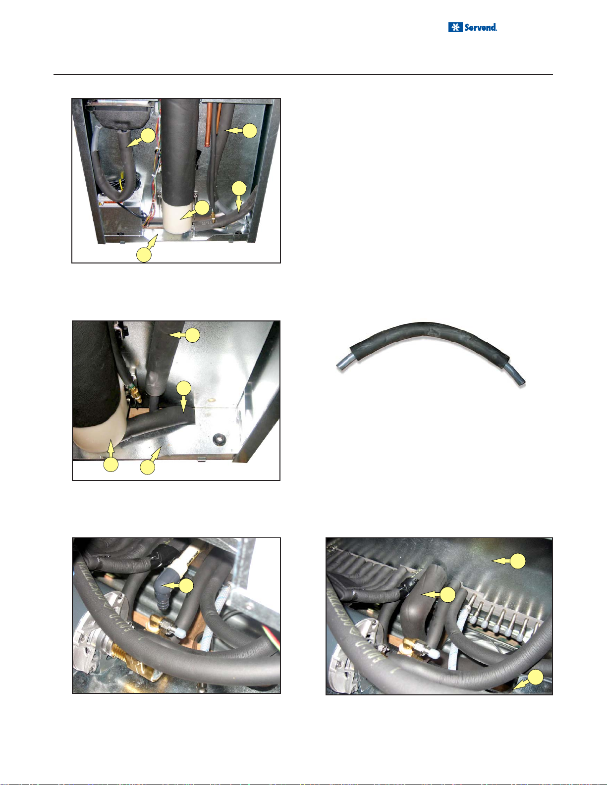
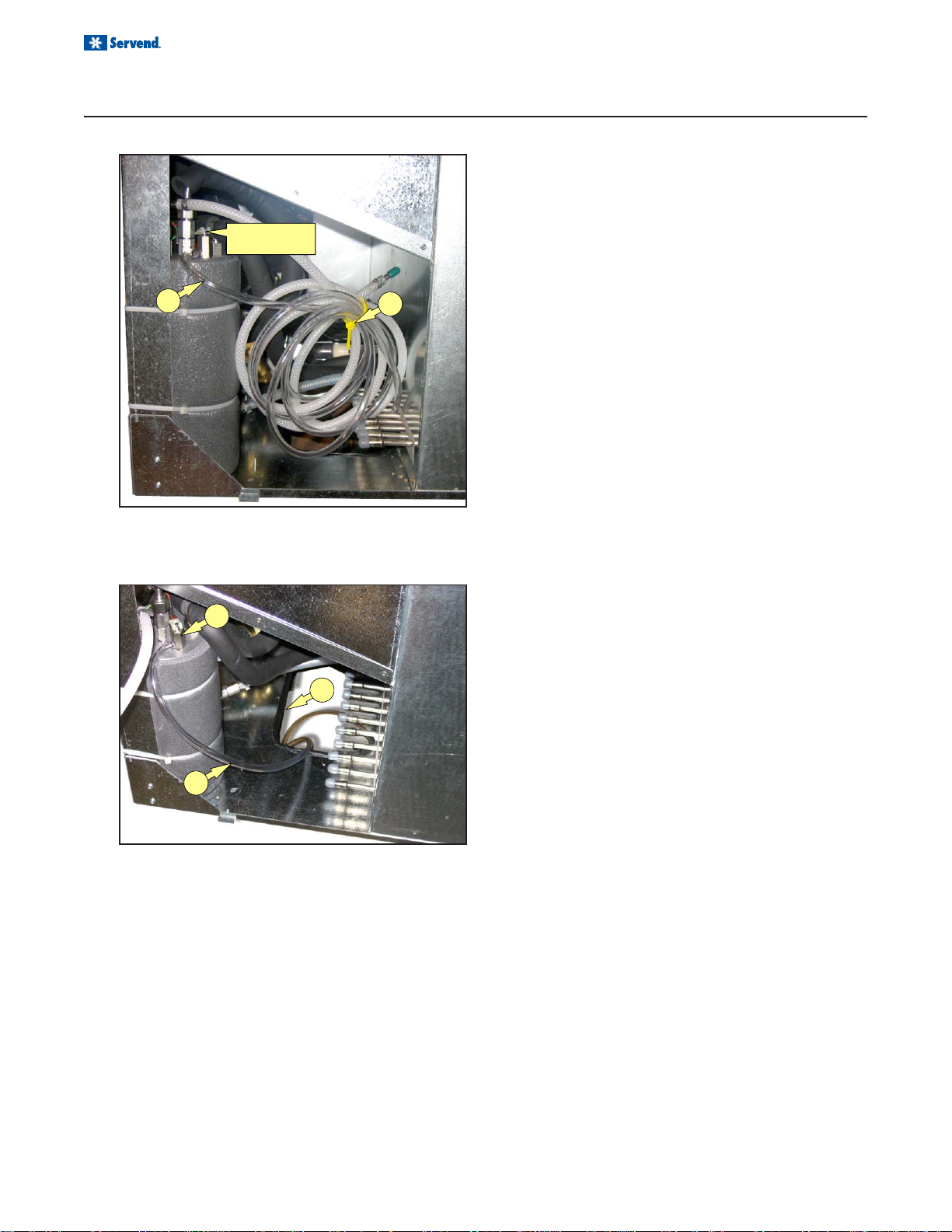
DRAINS
Right Side of unit as shipped:
1. During installation all drains on right side of the unit
B
C
E
must be properly routed.
2. Remove right side lower panel to access the drain
pan (A), icemaker (B) and auger (C) drains.
(see figure 1)
3. Route drain pan drain (A) through cut-out in baseplate (D) and follow all national plumbing codes.
4. Route Icemaker drain (B) through cut-out in baseplate (D) and follow all national plumbing codes.
(see figure 2)
5. Pull the insulation covering the auger drain (C) over
the clamp and fittings on the auger base (E).
6. Route auger drain (C) through cut-out in baseplate
(D) and follow all national plumbing codes.
Drain Kit:
B
FIGURE 3
C
1. Attach Drain Kit (figure 3) to barbed gray drain elbow (F). Use worm gear clamp that is provided to
secure the hose to the barb.
2. Route the drain hose through the opening in the
LP-3 base plate (D). Follow all local & national
E
D
FIGURE 2
plumbing codes.(see figure 5)
3. Pull the insulation (G) on the drain kit over the gray
drain elbow and the CPVC drain fitting until it is flush
with the stainless steel side panel (H).
F
FIGURE 4 FIGURE 5
11
Page 12
Installation and Service Manual
Pressure
Relief Valve
INSTALLATION
PURGE TUBE ROUTING
1. During installation of the LP-3 the carbonator tank
purge tube (A) must be properly routed to a drain.
The carbonator tank purge tube (A) may be accessed by removing the front panel of the LP-3. Clip
the tie strap (B) and uncoil the purge tube (A).
(see figure 1)
A
D
B
2. Route the carbonator tank purge tube (A) to the
opening beneath the ice bin drain elbow (C). Be
sure not to collapse or kink the carbonator tank
purge tube (A) during routing from the unit to the
drain. The purge tube (A) is connected to the pressure relief valve (D) on the carbonator tank and must
be routed to a drain.
(see figure 2)
FIGURE 1
3. Strap the carbonator tank purge tube to the drain
hose and route to a drain. Follow all local and national plumbing codes when routing the carbonator
tank purge tube to the drain.
C
12
A
FIGURE 2
Page 13
Installation and Service Manual
INSTALLATION
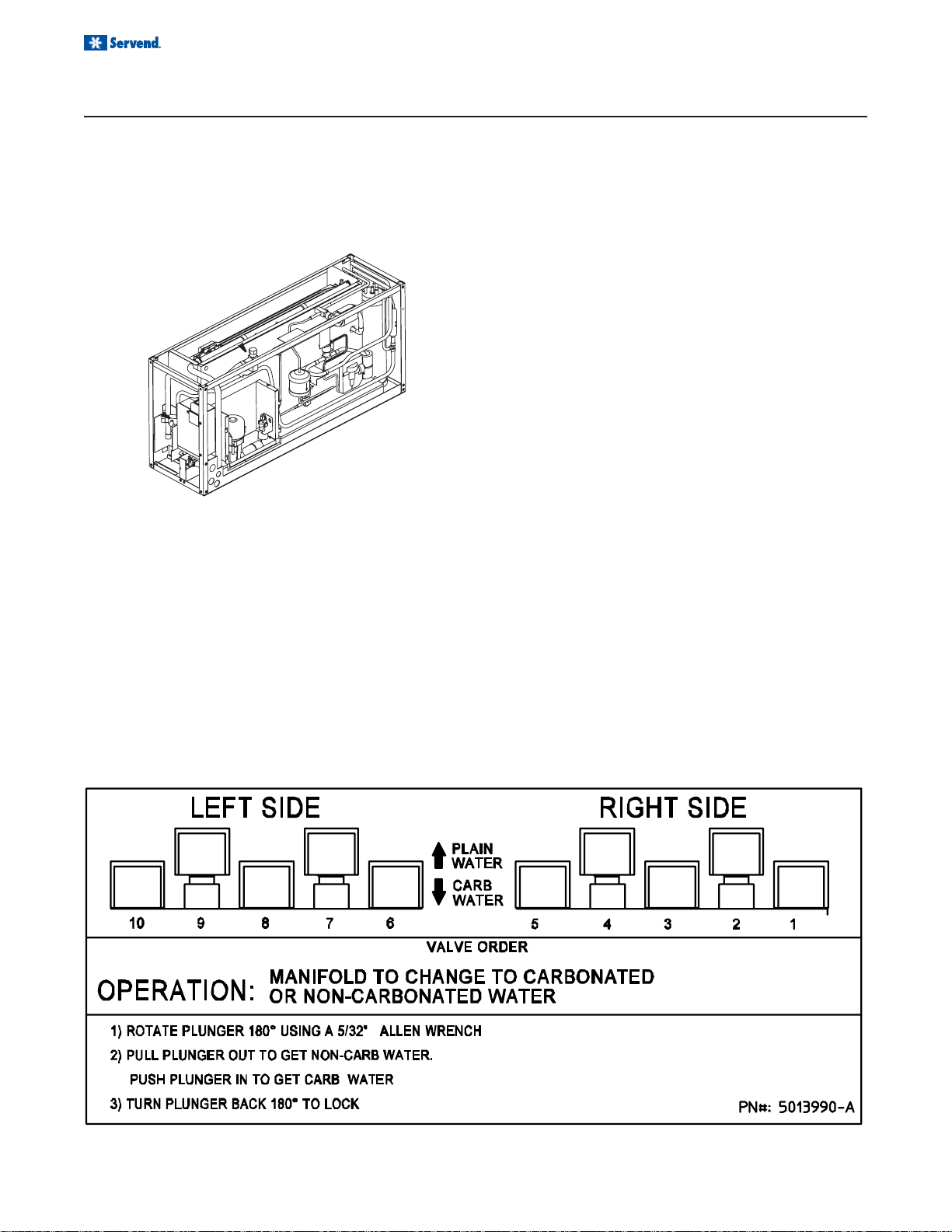
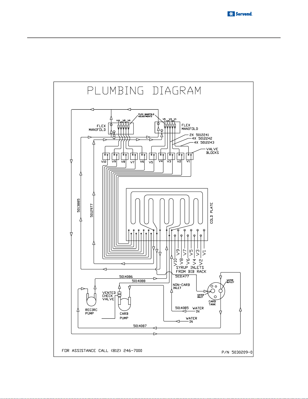
RECOMMENDED PLUMBING
The plumbing diagram is printed on a white vinyl label, normally located above the inlet tubes for syrup and water,
it can be accessed by removing the splash panel of the dispenser. The plumbing diagram label explains which inlet
coldplate fittings supply which dispenser valves and water manifolds.
NOTE: Valves are read from right to left.
A check valve must be installed in the water supply line 3 feet from the noncarbonated water connection
“PW”. Contact factory if not installed.
13
Page 14
Installation and Service Manual
OPERATION
UNIT INSPECTION
Thoroughly inspect the unit upon delivery. Immediately report any damage that occurred during transportation to
the delivery carrier. Request a written inspection report from a claims inspector to document any necessary claim.
SERIAL TAGS
At the time of installation both the LP-3 (ice and drink dispenser) and the SU1024-YC (ice maker) serial numbers
must be recorded.
LP-3
SERIAL TAG
The LP-3 serial number may be found by removing the
valve cover. The serial tag is located to the left of the left
hand Flexible Manifold above the #10 dispensing valve.
The SU1024-YC serial number may be found by removing the Left Side Plastic Cap. The serial tag is located on
the galvanized panel that protects the Receiver.
ICEMAKER
SERIAL TAG
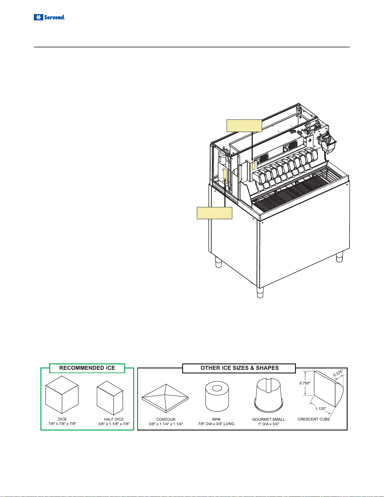
ICE RECOMMENDED FOR DISPENSING
Servend dispensers are designed to dispense hard, cube ice up to one-inch square. The ice shapes and sizes
listed above are recommended for dispensing. Warm “Super Cooled” Ice Before Dispensing “Super Cooled”
ice is not recommended for dispensing. “Super cooled” ice is ice that has been stored in freezers below 32oF.
Should it be necessary to temporarily use “super cooled” ice, allow the ice to warm at room temperature for 25
to 30 minutes before placing the ice in the dispenser.
Dispensing compressed flake “nugget” ice in Servend dispensers takes special handling. Most dispensers require
special bin components plus a universal ice management kit. Contact MBE regarding details for your particular
installation.
14
Page 15
OPERATION
EQUIPMENT
Installation and Service Manual
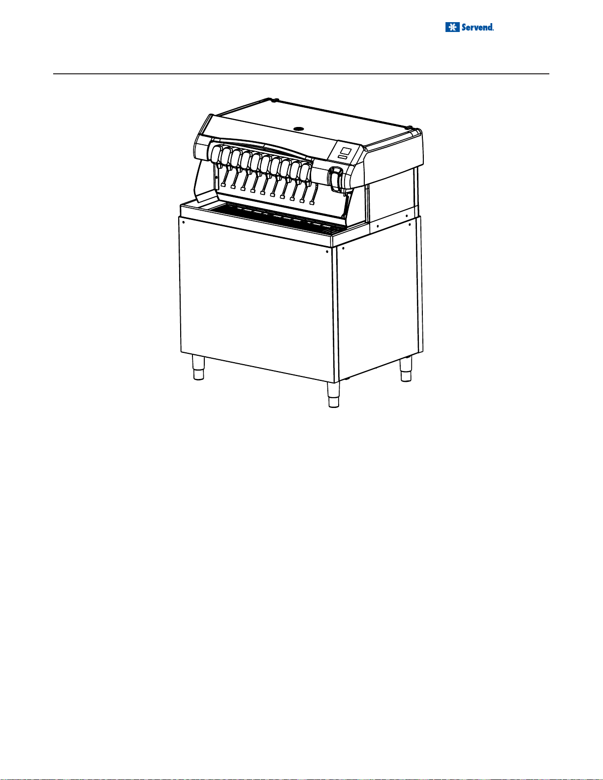
The LP-3 is a 10 flavor ice and beverage dispenser, with
the ice storage bin located below the counter top level. A
drink tower extends 19” above the counter top level. The
LP-3 is designed to fit into a 42.5” wide by 30.38” deep
space, and can be counter mounted (like a conventional
drop-in unit), or arranged as a stand alone with cosmetic
stainless panels.
Within the 19” drink tower is an optional 1000 lb/day remote ice cube maker, especially designed by Manitowoc
for this application.
Beverage cooling is accomplished by means of a cold
plate positioned below the storage bin, and the unit can
include an internally mounted or externally mounted carbonator system. In order to allow any valve to dispense
carbonated or non-carbonated beverages, two Servend
Flex Manifolds are incorporated into the tower.
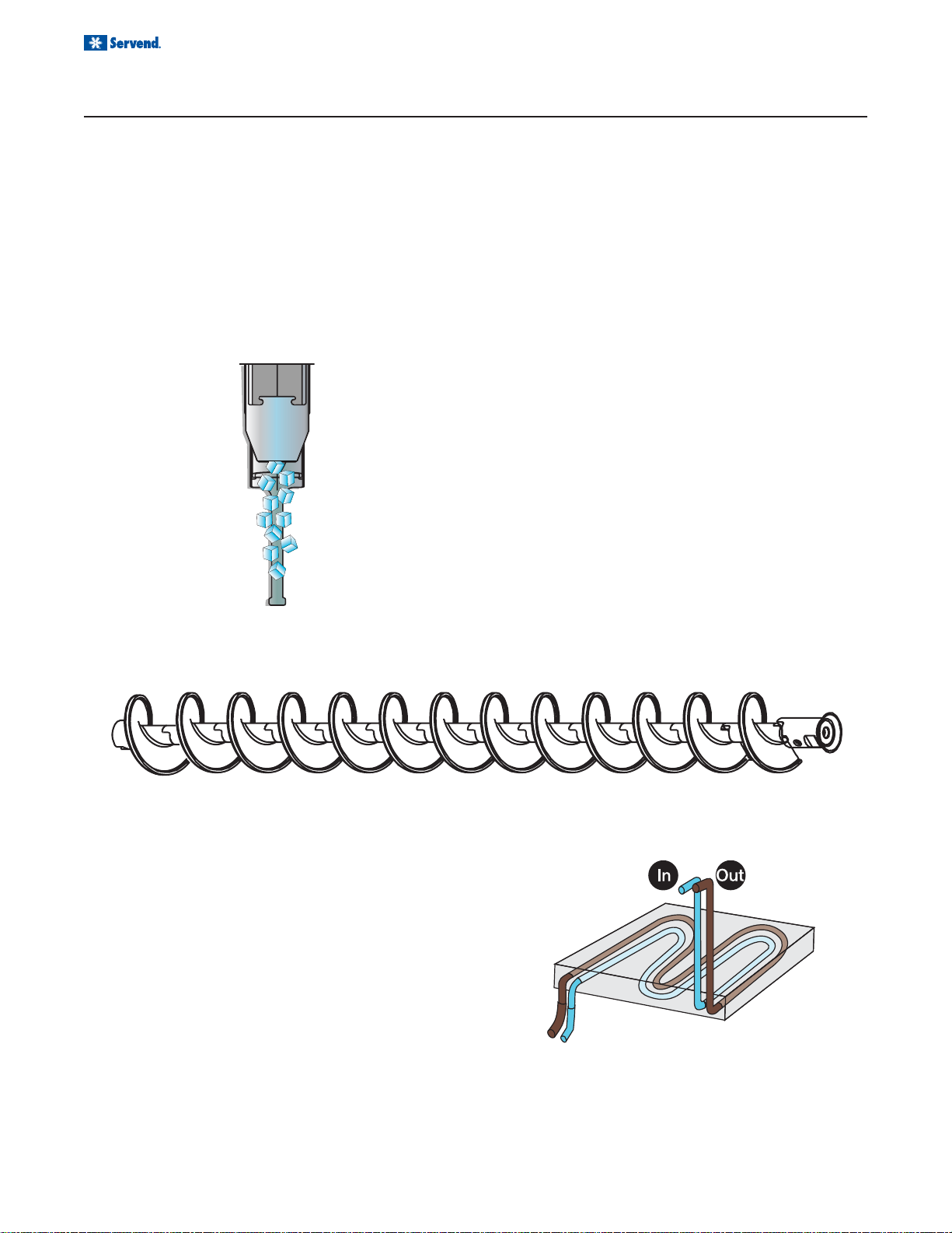
Ice is dispensed from the storage bin by means of the paddle
wheel into an auger which raises the ice to the top of the
tower where it is dispensed by means of a rocking chute.
The drink tower is enclosed by 5 panels, one on each
side and back, as well as a splash panel in front below
the valves, and a top panel. Safety switches will disable
the ice dispensing circuit when either the top panel or
the splash panel are removed. The drive motors for agitation and auger ice lifting are mounted using locking pins,
and thus can be removed for maintenance and cleaning
without tools. Access is provided for in place cleaning of
the ice maker. The ice maker water valve, water pan, curtain, and water pump can all be removed for service and
cleaning without removing the ice maker itself.
®
The LP-3 can be built in either a left hand or right hand ice
dispense arrangement. In the right hand configuration water/syrup lines from the BIB pumps are brought in to the
unit at the lower left, drains, electrical and refrigerant lines
on the right.
Drain hoses are provided for the waste water from the
cuber, spillage and melt water from the drain pan, and
melt water from the storage bin and auger. A water supply line is necessary for the ice maker and beverage system, each connecting to a 3/8” ID. beverage tube.
15
Page 16
Installation and Service Manual
OPERATION
ICE STORAGE AND DISPENSING
Ice is stored in the dispenser’s bin. Ice below the stainless steel bin liner is used to cool the aluminum cold plate, at
the bottom of the ice dispenser bin. Ice above the stainless steel bin liner is dispensed into the customer’s cup.
Ice is transported from the bin to the ice dispense point by the paddle wheel and vertical auger. The injection
molded paddle wheel has paddles which push the ice into a vertical auger that carries it to the dispense point.
ICE AGITATION
The paddle wheel and auger carry ice. Periodic agitation is standard on the LP-3. During periodic agitation, the
paddle wheel, auger and agitator turn for approximately three seconds every hour. The door lock prevents ice from
being dispensed during the agitation cycle.
ROCKING CHUTE ICE DISPENSING
As the customer presses the rocking chute, the arm at
the top left rear of the chute pushes upward on the door
lock. The door opens until it contacts the stops in the
mounting brackets. The plastic arm on the ice chute also
activates the lever of the ice dispensing switch. When
activated, the micro switch starts the gear motor and
auger motor. The gear motor turns the paddle wheel and
agitator bar, the auger motor turns the auger.
ICE AUGER
Ice is pushed into the auger by the paddlewheel. The auger lifts the ice from the bottom of the bin to the ice
dispense point at the rocking chute.
COLD PLATE BEVERAGE COOLING
A cold plate is a block of aluminum with serpentine stainless steel tubes molded inside the aluminum block. The
cold plate is approximately the same length and width
as the bottom of the dispenser bin. Ice sits on top of the
cold plate and cools the cold plate.
The stainless steel tubes inside the cold plate carry carbonated water (soda water), noncarbonated water (plain
water) and syrup to the beverage valves. While flowing
through the stainless steel tubes in the cold plate, water
and syrup are chilled to serving temperature.
BEVERAGE VALVES
Post-mix beverage valves are designed to precisely meter the flow of both water and syrup to obtain the proper
mixing ratio. The syrup and soda water components of the post-mix beverage are mixed as they leave the beverage valve.
16
Page 17

OPERATION
SPECIFICATIONS
Installation and Service Manual
Dimensions 44.4" X 31.1" X 57.3" (including top cover)
Weight 570 lbs (with ice 870 lbs)
Electrical Requirements 110 vac 60 hz 4 amps max.
Water 45 to 55 psi at 3 gpm
Ice Machine Options: Offered with 1000 lbs/day CVD model SU1024Y with remote
condenser
Drain Four 3/4" drain hoses to be routed to a floor drain
Syrups
Standard with Equipment: Internal carbonation or ambient carbonation for commercial
Options: With or without ice maker, right or left ice dispenser.
Listing/Approvals: UL and NSF
5
/16 barb connections for 10 flavors
applications.
17
Page 18

Installation and Service Manual
OPERATION
SPECIFICATIONS
B-I-B
The Bag-In-Box system refers to a plastic disposable bag. The B-I-B normally contains 5 gallons of syrup, however
some locations offer 2 1/2 or 3 gallon B-I-B units. This plastic bag is then held inside a cardboard or other container.
B-I-B systems are for post-mix applications only.
PUMPS
The syrup in a B-I-B system is delivered to the beverage system through gas operated pumps. These pumps
extract the syrup out of the bags forcing the syrup throughout the system.
AUTO BAG SELECTORS
These are used on higher volume B-I-B systems where two or more bags of the same product are connected to
one pump and one system. An auto bag selector is essentially a valve that automatically changes from one bag (or
series of bags) to another bag (or series of bags) of syrup as the bags empty, allowing a constant flow of product.
18
Page 19

Installation and Service Manual
OPERATION
Your syrup location can vary depending on the volume of beverages served and ease of accessibility. Your beverage system may set in a back storage room. Configurations are almost limitless. Check the temperatures expected
for the storage location. Adverse temperatures can affect the storage and quality of beverage products. It is recommended the temperature of storage location should not fall below 40o F or rise above 90o F.
BACK ROOM PACKAGE
1. Incoming tap water - should be at a minimum dy-
namic pressure of 40 psi and maximum of 55 psi.
2. Carbonator Water pump motor - Powers the water
pump. The water pump motor is part of the carbonator
pump deck.
3. Carbonator Water pump - Pumps tap water into the
carbonator tank. The water pump is part of the
carbonator. The incoming water for the carbonator
must be first ran through the pump before connecting
to the proper cold plate inlet.
4. Internal/External Carbonator tank - Combines CO
gas and tap water to form carbonated water. The “carbonator” is the carbonator tank, water pump and water pump motor.
5. CO2 cylinder - Holds highly pressurized carbon dioxide (CO2). The CO2 cylinder is a steel or aluminum
cylinder tank. CO2 gas flows through the primary pressure regulator.
6. BIB pressure gauge - Set for a minimum of 60 psi.
Indicates CO2 pressure going to B-I-B pumps.
7. Primary pressure regulator - Lowers the CO2 gas
pressure, to 75 psi, so the CO2 gas will be at the proper
pressure to enter the carbonator regulator.
8. Secondary pressure regulator - Lowers the CO2 gas
pressure before the CO2 gas flows to the syrup pump.
CO2 pressure, activates the syrup pump.
9. Syrup pump - Draws syrup out of the bag-in-box
syrup package. Syrup flows through the syrup lines
to the dispenser for chilling, then dispensing. There
2
is a syrup pump for each bag-in-box syrup system.
10. Bag-In-Box syrup cartons - Box which contains a
plastic bag, filled with syrup. Usually, six bag-in-box
cartons are placed on a rack.
19
Page 20
Installation and Service Manual
OPERATION
CARBONATION
The purpose of the carbonator is to take regular tap water at street water pressure (minimum 40 PSI dynamic or
flowing pressure) 3/8” water line, and increase the water to beverage system pressure (usually 75 PSI). This water
is then combined with the CO2 gas. Chilling the mixture before dispensing will assist in locking the carbon dioxide
into the water. After dispensing, the CO2 may be unlocked from the liquid. The CO2 will gradually leave the liquid
due to pressure and temperature changes.
Components
The components of the carbonator are: water pump, an
electric motor to operate the pump, carbonator tank
where the water & CO2 mix, and a water level control.
Operation
Carbon Dioxide (CO2) leaves the storage tank and arrives at the carbonator tank through the gas inlet. Water
supply enters the carbonator pump inlet at regular street
water line pressure (minimum 40 PSI dynamic or flowing pressure). The water pump increases the pressure
of the water, which allows the water to flow into the carbonator tank. The CO2 and the water mix together in the
carbonator to produce the carbonated water that is then
sent to the tank soda dispenser.
The agitation of the water & CO2 together in the tank
under high pressure creates the carbonated water. The
quality of carbonation (percent of CO2 mixed in the water) increases as the water temperature decreases and
exposure time increases.
The water level in the carbonator tank is controlled by a
water level control in the tank. This control turns the pump
motor off and on to maintain a preset level of liquid in the
tank. The water level control is two conductivity probes
wired to a liquid level control board.
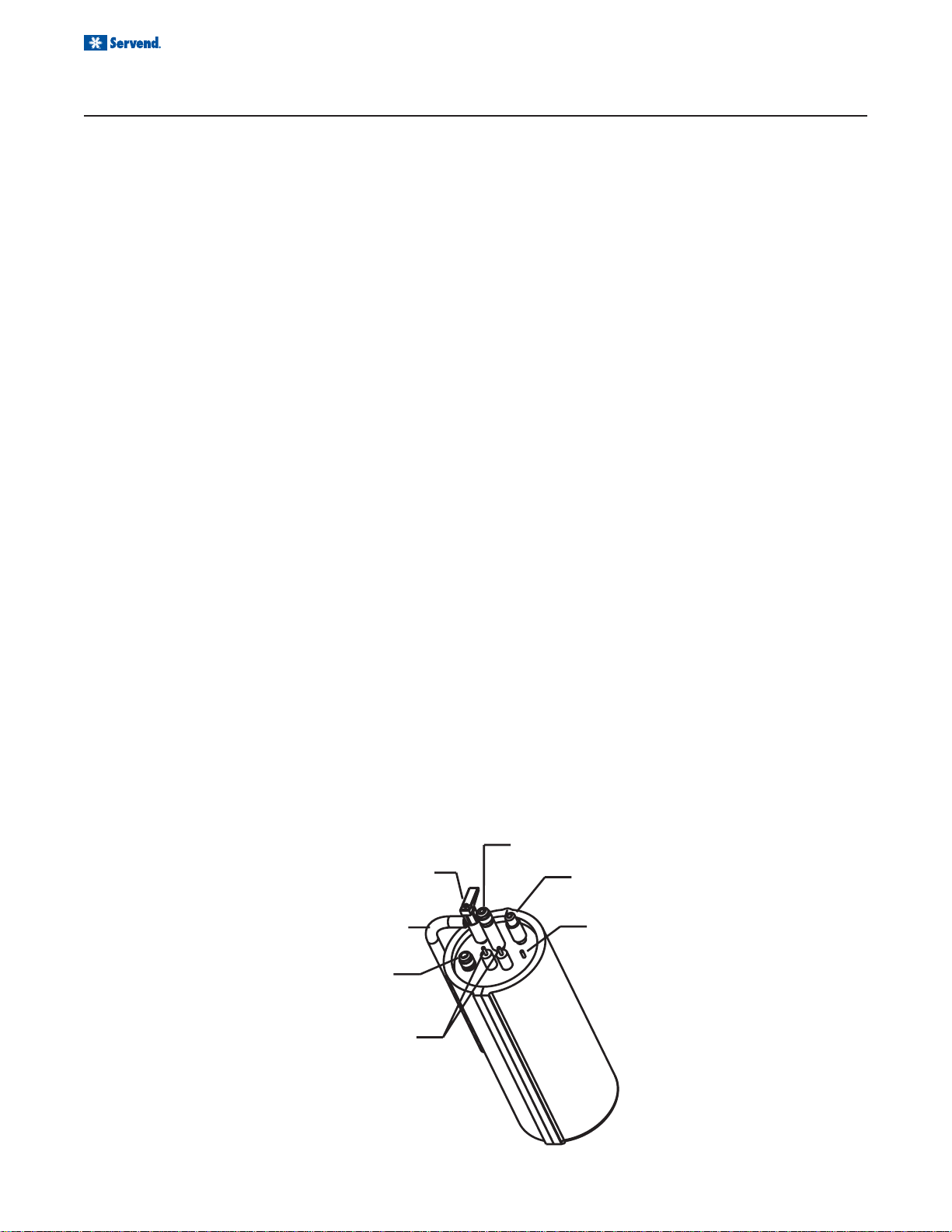
INTERNAL CARBONATION
The carbonator tank has two inlets and one outlet connection, as well as a relief valve and two conductivity
probes. The water inlet is topped by a 3/8" male flared
fitting. The carbonator will be pre-plumbed as it leaves
the factory. If the carbonator needs to be serviced or if
the fittings need to be replaced, make sure a nylon
washer is used inside each inlet fitting to prevent leaks.
The conductivity probes are used to control the level of
water inside the carbonator tank. The red probe, or the
“high” probe, is the shorter of the two. When the level
of the water reaches the bottom of the red probe, the
pump shuts off. The pump starts when the water level
inside the tank goes below the bottom tip of the of the
black or "low" probe. Both probes are wired to the elec-
Pressure
Relief
Purge
Tube
Carbonated
water Outlet
tronic liquid level control, which is a circuit board
mounted inside the electrical box that activates the
pump and motor. Removing the cover of the electrical
box will grant access to the circuit board. As the control
receives a signal from the conductivity probes, it activates the pump motor, which will pump water into the
carbonator until the water reaches the high probe.
The pump is a standard 125 GPH brass rotary vane
pump. The flared fittings accept the same swivel/barb
connectors used on the carbonator water connections.
Also, water enters the pump from the water source on
the side that has the strainer.
Water
Inlet
CO
2
Inlet
Ground
20
Electronic
Probes
Page 21

Installation and Service Manual
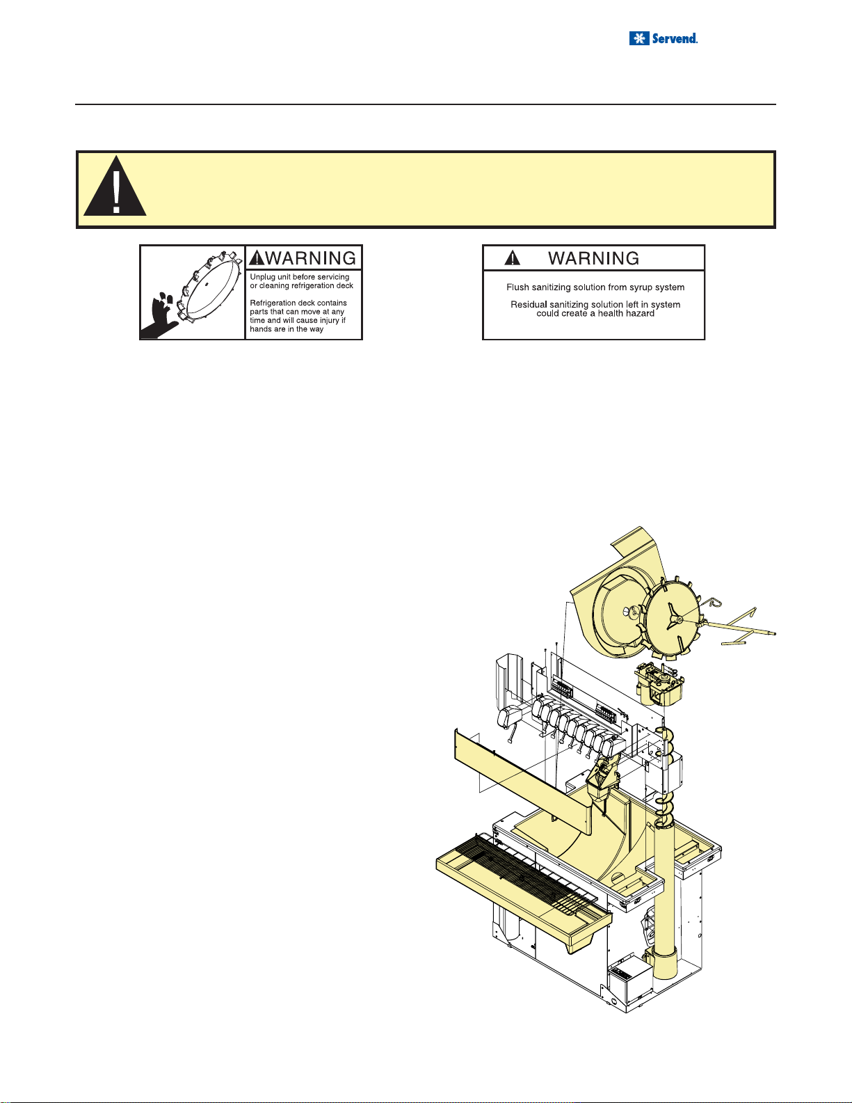
USER MAINTENANCE
HOW TO DISASSEMBLE FOR CLEANING OR MAINTENANCE
1. Disconnect electrical power to the unit.
2. Remove thumb screws holding plastic splash
guards and stainless splash panel.
3. Remove grid and drainpan.
4. Release the plastic latches on the back of either
side of the lid assembly. (see Detail A)
5. Slide the lid assembly forward and lift to remove.
6. Remove the plastic side panel assemblies.
7. Remove all ice from the ice storage bin.
8. Rotate the agitator arm so the paddle wheel pin
handle is pointing up, toward the ceiling.
9. Loosen the hand-removable paddle wheel pin from
the agitator by twisting counter clockwise until it
snaps from the agitator bar.
10. Then remove the paddle wheel pin from the hole in
the agitator. Push the agitator bar toward the back
of the unit until the agitator is free of the paddle
wheel hub and remove the agitator.
11. Remove the bin liner.
12. Remove horizontal tower cover brace then remove
the auger motor assembly by pulling the 7 pins holding it in place, disconnecting the 2 sets of insulated
quick slides to the motor, and lifting the assembly
straight up and out of the unit.
13. Lift the auger and auger tube up and out of the unit.
14. Remove the auger transition by pulling the 2 pins
holding it in place.
15. Remove the ice chute assembly and spout.
CLEANING CHECKLIST
• Check CO
the primary regulator gauge will point to a shaded area
that reads “Low CO2” or “Change CO2 Cylinder.”
supply. If CO2 supply is low, an arrow on
2
• Check syrup supply.
• Clean drain pan, grid, and splash panel.
• Clean the valve nozzles and diffusers.
21
Page 22

Installation and Service Manual
USER MAINTENANCE
DAILY CLEANING
CAUTION: Use only warm soapy water to clean the exterior of the tower. Do not use solvents or
other cleaning agents
drain pan can eventually crack the drain pan, especially if the drain pan is cold or still contains ice.
All cleaning must meet your local health department regulations. The following cleaning instructions are
. Do not pour hot coffee into the drain pan. Pouring hot coffee down the
provided as a guide.
Clean the exterior, nozzles and diffusers:
1. Turn off the key switch located on either right or left
side of the unit.
2. Lift the grid and remove it from the drain pan.
3. Using mild soap, warm water and a clean cloth, wipe
the drain pan and splash panel. Then, rinse with clean,
warm water. Allow plenty of warm (not hot) water to
run down the drain of the drain pan, to remove syrup
residue that can clog the drain opening.
4. Wash the grid, then rinse with clean water. Place
the grid back in the drain pan.
5. Wash all exterior surfaces of the unit with warm
water and a clean cloth. Wipe again with a clean,
dry cloth.
Clean the dispensing valves:
6. Remove nozzles and diffusers from beverage
valves.
7. Rinse nozzle and diffuser with warm, clean water.
8. Clean nozzles and diffusers with soapy water and
a soft bristle brush.
9. Clean the underside of the beverage valves with
warm, soapy water. Rinse with clean damp towel.
10. Replace nozzles and diffusers on valves.
11. Turn on the key switch.
22
Page 23
Installation and Service Manual
USER MAINTENANCE
MONTHLY CLEANING
Scheduled cleaning must be in compliance with local health codes. This cleaning schedule is a
recommendation. Follow cleaning and sanitizing instructions found in the Manitowoc manual to
clean and sanitize the icemaker. The LP-3 drainpan and splash panel must be removed before
cleaning the icemaker.
CLEANING AND SANITIZING OF THE DISPENSER
Note: Sanitize the dispenser at initial start-up in addition to monthly sanitizing.
Mix a solution of mild, nonabrasive detergent to clean the dispenser bin and components. Using a clean cloth or a
soft bristle brush, clean the following dispenser parts:
• Cold plate
• Ice storage bin, including the
• Agitator
• Agitator Pin
• Bin liner & support
• Drainpan support bracket
• Auger
• Auger tube
• Auger transition
• Ice chute outer bracket
• Ice chute
• Ice chute door
• Ice chute lock
• Ice chute spout
• Paddle wheel
• Paddle wheel bushing
• Paddle wheel area
Rinse all parts in clean, running water. Mix a sanitizing
solution of ¼ ounce liquid, unscented laundry bleach
(5.25% Cl Na O concentration) for each gallon of water,
to supply 100 PPM of available chlorine. Using this solution and a clean cloth or soft bristle brush, clean the
dispenser parts listed above. Allow parts to air-dry then
reassemble.
23
Page 24
Installation and Service Manual
USER MAINTENANCE
BEVERAGE SYSTEM CLEANING
Sanitize the beverage system at initial start-up as well as during regularly scheduled cleaning. The drain pan must
be in place under soda valves, to carry away detergent and sanitizing agents that will be flushed through valves.
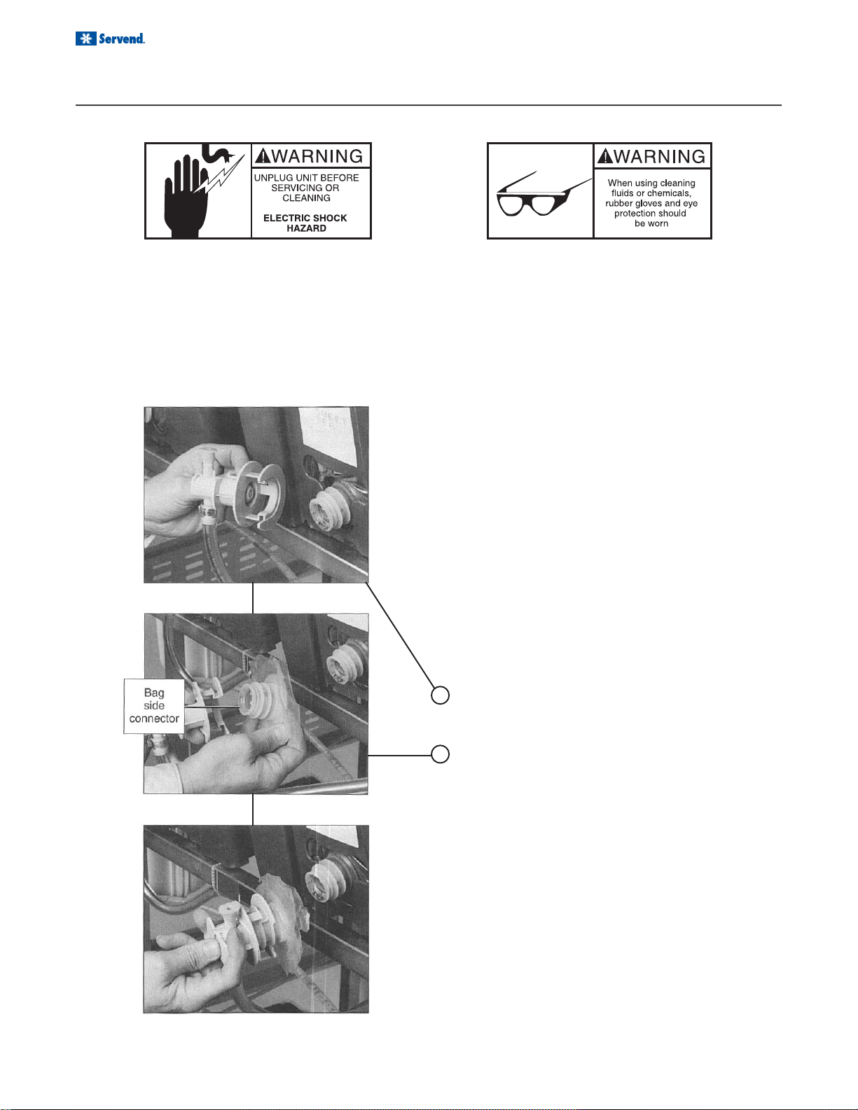
BAG-IN-BOX SYSTEM
The procedure below is for the sanitation of one syrup circuit at a time. Repeat to sanitize additional circuits.
You will need the following items to clean and sanitize
the Bag-in-Box (BIB) beverage system:
• Three (3) clean buckets
• Plastic brush or soft cloth
• Mild detergent
• Unscented bleach (5% Na CL O) or
Commercial sanitizer
• Bag-In-Box bag connector
1. Prepare the following in the buckets:
• Bucket 1 - warm to hot tap water for rinsing.
• Bucket 2 - mild detergent and warm to hot water.
• Bucket 3 - mix a solution of unscented bleach
(5% Na CL O) or commercial sanitizer and warm
to hot water. Mixture should supply 100 PPM available chlorine (1/4 oz. bleach to 1 gallon water).
2. Disconnect the “syrup-line side” of the bag-in-box
connector.
3. Rinse connector with warm tap water.
4. Connect syrup connector to BIB connector and immerse both into Bucket 1. A “bag-side” connector
can be created by cutting the connector from an
empty disposable syrup bag.
5. Draw rinse water through system until clean water
is dispensed. Most beverage valves allow the syrup
side to be manually activated by depressing the
syrup pallet.
6. Connect Bucket 2 to system.
7. Draw detergent solution through system until solution is dispensed.
8. Repeat steps 2-7 until all syrup circuits contain detergent solution.
9. Allow detergent solution to remain in the system for
5 minutes.
24
Page 25

USER MAINTENANCE
BAG-IN-BOX SYSTEM
Installation and Service Manual
10. Connect Bucket 3 to system.
11. Draw sanitizing solution through system until solution is dispensed.
12. Repeat step 11 until all syrup circuits contain sanitizer solution.
13. Allow sanitizer solution to remain in system for 15
minutes.
14. Remove nozzles and diffusers from beverage valves.
15. Scrub nozzles, diffusers and all removable valve
parts (except electrical parts) with a plastic brush
or a soft cloth and the detergent solution.
16. Soak nozzles, diffusers and removable valve parts
(except electrical parts) in sanitizer for 15 minutes.
17. Replace nozzles, diffusers and valve parts.
18. Connect Bucket 1 to system.
19. Draw rinse water through system until no presence
of sanitizer is detected.
20. Attach syrup connectors to BIB’s.
21. Draw syrup through system until only syrup is dispensed.
22. Discard first 2 drinks.
PREVENTATIVE MAINTENANCE
Preventative maintenance is a vital part of keeping your dispenser in top condition. Following the guidelines below
will assist you in continued trouble free operation of your unit.
1. Conduct daily maintenance of the machine.
2. Perform monthly maintenance of the machine.
3. Perform periodic maintenance and sanitizing of beverage system.
4. Do not overfill the dispenser bin with ice.
5. Do not allow the dispenser to sit for prolonged periods of non use with ice in the bin.
6. Most ice dispenser service problems are caused by
low usage of the ice dispenser.
7. Do not allow ice to remain in the bin more than a day
in order to prevent ice from freezing together and/or
stagnant ice.
Possible excess ice storage reasons:
• Storage capacity exceeds daily requirements.
• Low demand during the off season.
• Dispenser oversized with future growth in mind.
Lower ice storage to meet one day’s needs. If you manually fill ice, fill only with the appropriate amount of ice. Fill
the dispenser with fresh ice each morning. Do not fill the
dispenser at night just before shut down. Ice cubes can
freeze together if not dispensed.
Contact MBE at 1-800-367-4233 for more information
about our ProActive Maintenance Program.
25
Page 26
Installation and Service Manual
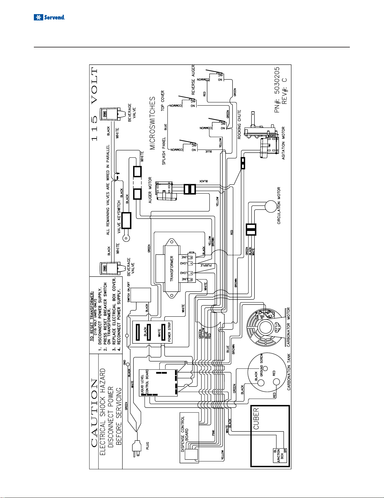
EXPLODED VIEWS, PARTS & DIAGRAMS
115V WIRING DIAGRAM
26
Page 27

Installation and Service Manual
EXPLODED VIEWS, PARTS & DIAGRAMS
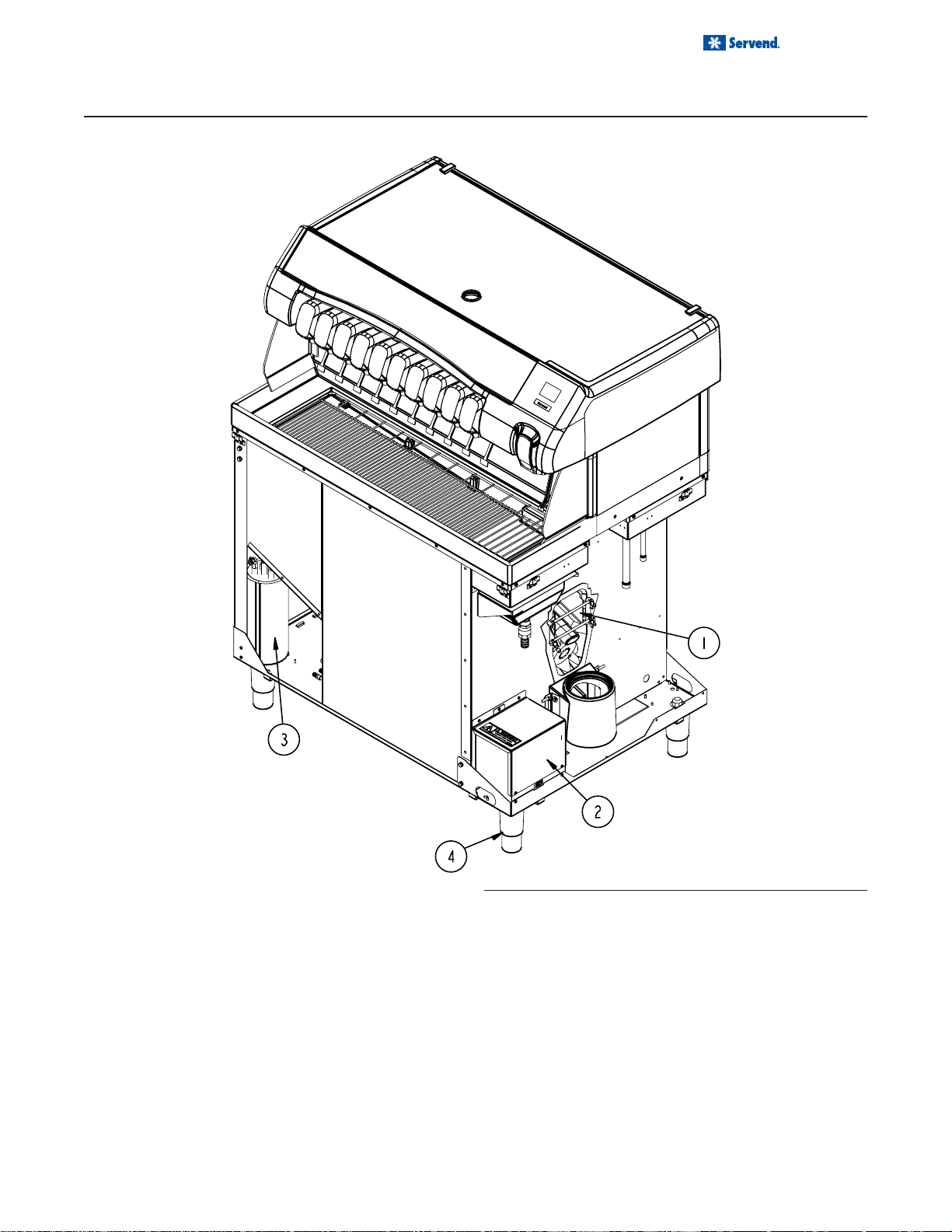
COVERS & PANELS
NO Part# Description
1 5029883 CABINET GALV
2 020000214 RH COVER ASSM
3 020000215 LH COVER ASSM
4 020000216 LID ASSM
27
Page 28

Installation and Service Manual
EXPLODED VIEWS, PARTS & DIAGRAMS
SPLASH PANEL, DRAINPAN & CUBER
28
No. Part Number Description
1 5012090 GRID
2 5012238 DRAINPAN RH
3 5012311 CUBER 120V
Page 29

Installation and Service Manual
EXPLODED VIEWS, PARTS & DIAGRAMS
PANELS & LID BONNET
NO Part Number Description
1 000000246 LABEL LOGO SNOWFLAKE
2 00850809 NUT # 4-40 HEX BRASS
3 0901001 SCR #8X1/2" SS PH TR HD
4 5000888 CLIP PUSH ON
5 5031260 LENS
6 5031525 GROMMET FINGER
7 5031550 LABEL LOGO SERVEND
8 5031590 LABEL ICE
NO Part Number Description
9 020000141 COVER FRONT
10 020000144 TRIM, TOWER
11 020000145 TRIM, TOWER LOGO
12 020000207 BSHG BONNET ANGLED
13 020000213 LID, SS TOWER RH
14 020001321 SPACER, LATCH
15 020001323 LATCH PLAS
16 020001328 SCR 4-40 X 1/2
29
Page 30

Installation and Service Manual
EXPLODED VIEWS, PARTS & DIAGRAMS
AUGER, AGITATION & DRAIN
30
Page 31
Installation and Service Manual
EXPLODED VIEWS, PARTS & DIAGRAMS
LEGS, CARB TANK & ELECTRIC BOX
No Part Number Description
1 5029874 MNT MOTOR 120V
2 5029876 ELEC 120/60
3 5029887 TANK CARB
4 5030236 LEG
31
Page 32

Installation and Service Manual
EXPLODED VIEWS, PARTS & DIAGRAMS
AUGER DRIVE, VALVE MOUNT, ROCKING CHUTE, PUMP
NO. Part Number Description
1 5029884 BOM BASE
2 5029872 CAP VLV MNT RH
3 5028889 AREA RH PADDLEWHEEL
4 5029888 PUMP CARB 120V
5 5014007 PUMP RECIRC 120V
6 5012308 AUGER DRIVE 120V
7 5012326 CHUTE ROCKING
32
NO. Part Number Description
8 5012615 VLV FLO 464HF SL GP COVER
9 5000220 KEYSWITCH
10 020001299 BRKT SAFETY SWITCH
11 100703 MICROSWITCH
12 0900901 SCR 6-32 X 1" SS PH RHMS
13 0902101 NUT 6-32 HEX SS
Page 33

Installation and Service Manual
EXPLODED VIEWS, PARTS & DIAGRAMS
120V AUGER DRIVE
33
Page 34

Installation and Service Manual
EXPLODED VIEWS, PARTS & DIAGRAMS
120V CUBER
NO. Part # Description
1 5031580 CUBER BRAZED EXT
2 5029830 BRACE RT SIDE PANEL
3 5029832 BRACE LFT SIDE PANEL
4 5029831 BRACE BACK PANEL
5 5011940 SCREW 8-32 X 1/2
6 5012891 WRAP BACK
7 5012933 TRIM EVAPORATOR WRAP BACK1
8 5012281 SCREW 8-32 X 1/4 ES FORM 7
9 0901001 SCR #8X1/2" SS PH TR HD A4
10 0900240 CLIP TINN C191728Z4
11 5031078 SPACER ICEMAKER
12 5012892 WRAP RIGHT
13 5012893 WRAP LEFT
14 5012934 TRIM EVAPORATOR WRAP SIDE2
15 5029806 RIVNUT 10-32
16 020001298 BRKT REAR PANEL SUP
17 020000226 WRAP BACK
18 020001323 Latch Plas
19 020001322 SCREW #4 X 1/2 SELF TAP 4
RIGHT SIDE BONNET COVER LEFT SIDE BONNET COVER
NO Part # Description
1 0901001 SCR #8X1/2" SS PH TR HD A
2 0901803 WASHER FLAT #10 ZINC
3 020000142 CAP TOWER END
4 020000212 SUPPORT BONNET SIDE
NO Part # Description
1 0901001 SCR #8X1/2" SS PH TR HD A
2 0901803 WASHER FLAT #10 ZINC
3 020000143 CAP TOWER END
4 020000212 SUPPORT BONNET SIDE
34
Page 35

Installation and Service Manual
EXPLODED VIEWS, PARTS & DIAGRAMS
120V CARB PUMP & TANK ASSEMBLY
No. Part Number Description
1 1701110 NUT 3/8"X9/16" SWIVEL FITTING
2 1701115 Washer 3/8" Black Nylon
3 1701301 CLAMP OTR 1/2" 13.3-706R
4 5009025 FITTING SWIVEL 3/8" BARB
5 5009613 PUMP HEAD CARB 125 GPH
6 5009983 FITTING 3/8X3/8 NPT ELBOW
7 5010781 FITTING 3/8 BARB SW/ELBOW
8 5028931 MOTOR CARB PUMP 115V
9 5031042 VALVE CHK VENTED 3/8" NPT X 3/8" FLARE
10 5030533 TUBE CARB TANK PURGE
35
Page 36

Installation and Service Manual
EXPLODED VIEWS, PARTS & DIAGRAMS
AUGER & ROCKING CHUTE
36
Page 37

Installation and Service Manual
EXPLODED VIEWS, PARTS & DIAGRAMS
VALVE MOUNT CAP & AGITATOR MOTOR
37
Page 38

Installation and Service Manual
EXPLODED VIEWS, PARTS & DIAGRAMS
AUGER TRANSITION & 120V ELECTRIC BOX
38
Page 39

Installation and Service Manual
EXPLODED VIEWS, PARTS & DIAGRAMS
BIN
39
Page 40

Installation and Service Manual
9
9
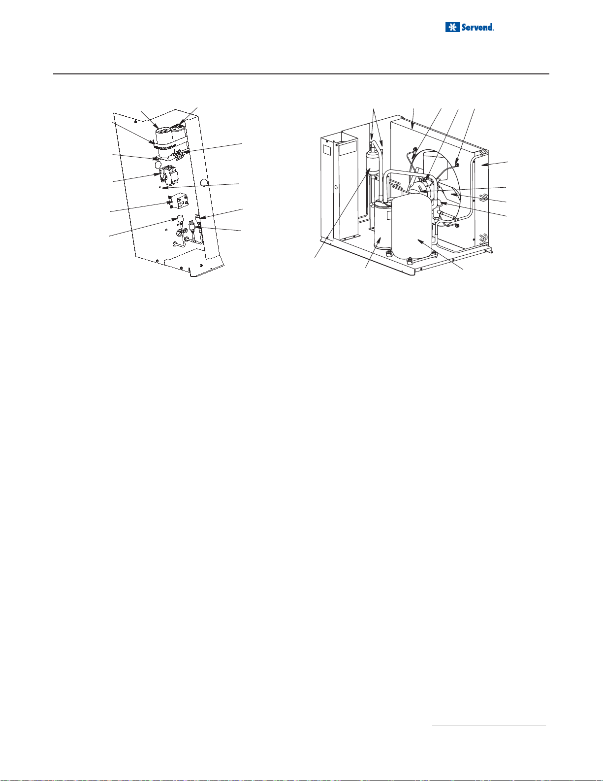
MANITOWOC® SU1024YC ICEMAKER
CONTROL BOX & EVAPORATOR COMPARTMENT
5
6
7
1, 2
10
9
8
SV3000
DESCRIPTION PART NUMBER
1 Control Board (for use with all voltages) . . . . . . . . . . . . . . . . . . . . . . . . . . . . . . . . . . . . . . . . . . . . . . 76-2782-3
27 amp Fuse Mounted on Control Board. . . . . . . . . . . . . . . . . . . . . . . . . . . . . . . . . . . . . . . . . . . . . . 25-1100-3
3 Wiring Harness Control Box (Not shown)
a. 115V/60 Hz/1 ph . . . . . . . . . . . . . . . . . . . . . . . . . . . . . . . . . . . . . . . . . . . . . . . . . . . . . . . . . . . . . . 20-0077-3
b. 208-230V/60 Hz/1 ph. . . . . . . . . . . . . . . . . . . . . . . . . . . . . . . . . . . . . . . . . . . . . . . . . . . . . . . . . . . 20-0077-3
c. 230V/50 Hz/1 ph . . . . . . . . . . . . . . . . . . . . . . . . . . . . . . . . . . . . . . . . . . . . . . . . . . . . . . . . . . . . . . 20-0077-3
4 Wiring Harn ess From Control Box (Not shown)
a. 115V/60 Hz/1 ph . . . . . . . . . . . . . . . . . . . . . . . . . . . . . . . . . . . . . . . . . . . . . . . . . . . . . . . . . . . . . . 20-0112-3
b. 208-230V/60 Hz/1 ph. . . . . . . . . . . . . . . . . . . . . . . . . . . . . . . . . . . . . . . . . . . . . . . . . . . . . . . . . . . 20-0112-3
c. 230V/50 Hz/1 ph . . . . . . . . . . . . . . . . . . . . . . . . . . . . . . . . . . . . . . . . . . . . . . . . . . . . . . . . . . . . . . 20-0112-3
5 Toggle Swit ch (Only). . . . . . . . . . . . . . . . . . . . . . . . . . . . . . . . . . . . . . . . . . . . . . . . . . . . . . . . . . . . . 23-0134-3
a. Toggle Switch With Wiring Harness Attached. . . . . . . . . . . . . . . . . . . . . . . . . . . . . . . . . . . . . . . . 20-0113-3
b. Mounting Box. . . . . . . . . . . . . . . . . . . . . . . . . . . . . . . . . . . . . . . . . . . . . . . . . . . . . . . . . . . . . . . . . 40-0056-3
Miscellane ous Screws, Support s, etc.
6 Control Box. . . . . . . . . . . . . . . . . . . . . . . . . . . . . . . . . . . . . . . . . . . . . . . . . . . . . . . . . . . . . . . . . . . . . 604739-1
7 Control Box Cover . . . . . . . . . . . . . . . . . . . . . . . . . . . . . . . . . . . . . . . . . . . . . . . . . . . . . . . . . . . . . . . 76-0116-3
8 Control Board Mounting Supports . . . . . . . . . . . . . . . . . . . . . . . . . . . . . . . . . . . . . . . . . . . . . . . . . . . 43-0225-3
9 Screw, #10-24 x .50 Ground. . . . . . . . . . . . . . . . . . . . . . . . . . . . . . . . . . . . . . . . . . . . . . . . . . . . . . . . 52-0216-
10 Screw, 10 x 24 x .50 Phillips. . . . . . . . . . . . . . . . . . . . . . . . . . . . . . . . . . . . . . . . . . . . . . . . . . . . . . . . 52-0209-
12
1
6
13
2
7
14
5
11
3, 8
DESCRIPTION PART NUMBER
9
10
4
1 Evaporator Assembly Half Dice Cube . . . . . . . . . . . . . . . . . . . . . . . . . . . . . . . . . . . . . . . . . . . . . . . . . 76-0096-3
2 Ice Thickness Control Probe . . . . . . . . . . . . . . . . . . . . . . . . . . . . . . . . . . . . . . . . . . . . . . . . . . . . . . . . 76-2781-3
3 Magnetic Bin Switch (Mounted to Evaporator). . . . . . . . . . . . . . . . . . . . . . . . . . . . . . . . . . . . . . . . . . . 23-0148-3
4 Water Trough. . . . . . . . . . . . . . . . . . . . . . . . . . . . . . . . . . . . . . . . . . . . . . . . . . . . . . . . . . . . . . . . . . . . 40-0468-3
5 Water Curtain. . . . . . . . . . . . . . . . . . . . . . . . . . . . . . . . . . . . . . . . . . . . . . . . . . . . . . . . . . . . . . . . . . . . 40-0944-3
6 Water Distribution Tube . . . . . . . . . . . . . . . . . . . . . . . . . . . . . . . . . . . . . . . . . . . . . . . . . . . . . . . . . . . . 43-0322-3
7 Vinyl Tubing Water Distribution Tube to Water Pump . . . . . . . . . . . . . . . . . . . . . . . . . . . . . . . . . . . . . 40-0412-3
Miscellaneous Bracket s, Screws, etc.
8 Water Curtain Magnet With Attachment Clip . . . . . . . . . . . . . . . . . . . . . . . . . . . . . . . . . . . . . . . . . . . . 76-2802-3
9 Quarter Turn Fastener Male (Water Trough and Water Pump Mounting) . . . . . . . . . . . . . . . . . . . . . . 50-0045-3
10 Quarter Turn Fastener Receptacle Female (Water Trough and Water Pump Mounting). . . . . . . . . . . 56-5085-3
11 Screw 10 x 24 x .75 with washer Evaporator Mounting . . . . . . . . . . . . . . . . . . . . . . . . . . . . . . . . . . . . 52-0218-9
12 Screw, #8-32 x .63 Water Distribution Tube Mounting. . . . . . . . . . . . . . . . . . . . . . . . . . . . . . . . . . . . . 50-0001-3
13 Evaporator Top Molding and Gasket Assembly . . . . . . . . . . . . . . . . . . . . . . . . . . . . . . . . . . . . . . . . . 76-2801-3
14 Water Curtain Pin Assembly . . . . . . . . . . . . . . . . . . . . . . . . . . . . . . . . . . . . . . . . . . . . . . . . . . . . . . . . 76-2856-3
Refer to Cross Reference Guide
40
PT370
Page 41

MANITOWOC® SU1024YC ICEMAKER
REFRIGERATION COMPARTMENT
8
2
3
Installation and Service Manual
5
6
18
14
19
16
1
11
17
13
4
14
12
10
9
7
41
Page 42

Installation and Service Manual
MANITOWOC® SU1024YC ICEMAKER
REFRIGERATION COMPARTMENT
DESCRIPTION PART NUMBER
1 Water Dump Valve
a. Dump Valve Assembly without Electrical Coil. . . . . . . . . . . . . . . . . . . . . . . . . . . . . . . . . . . . . . . . . 24-0520-3
b. 115V/60 Hz Coil Only . . . . . . . . . . . . . . . . . . . . . . . . . . . . . . . . . . . . . . . . . . . . . . . . . . . . . . . . . . . 24-0521-3
c. 208/230V 50/60 Hz Coil Only . . . . . . . . . . . . . . . . . . . . . . . . . . . . . . . . . . . . . . . . . . . . . . . . . . . . . 24-0522-3
d. Dump Valve Rebuild Kit . . . . . . . . . . . . . . . . . . . . . . . . . . . . . . . . . . . . . . . . . . . . . . . . . . . . . . . . . 24-0501-3
2 Manual Shut -off Valve Suct ion Line . . . . . . . . . . . . . . . . . . . . . . . . . . . . . . . . . . . . . . . . . . . . . . . . . 83-7301-3
a. Valve Cap . . . . . . . . . . . . . . . . . . . . . . . . . . . . . . . . . . . . . . . . . . . . . . . . . . . . . . . . . . . . . . . . . . . . 83-7327-3
3 Manual Shut -off Valve Liquid Line . . . . . . . . . . . . . . . . . . . . . . . . . . . . . . . . . . . . . . . . . . . . . . . . . . 83-7300-3
a. Valve Cap . . . . . . . . . . . . . . . . . . . . . . . . . . . . . . . . . . . . . . . . . . . . . . . . . . . . . . . . . . . . . . . . . . . . 83-7302-3
4 Receiver. . . . . . . . . . . . . . . . . . . . . . . . . . . . . . . . . . . . . . . . . . . . . . . . . . . . . . . . . . . . . . . . . . . . . . . . 82-5058-3
a. Equalizer Tube (Connects The Receivers). . . . . . . . . . . . . . . . . . . . . . . . . . . . . . . . . . . . . . . . . . . 30-0154-3
5 Check Valve. . . . . . . . . . . . . . . . . . . . . . . . . . . . . . . . . . . . . . . . . . . . . . . . . . . . . . . . . . . . . . . . . . . . . 83-7315-9
6 Expansion V alve. . . . . . . . . . . . . . . . . . . . . . . . . . . . . . . . . . . . . . . . . . . . . . . . . . . . . . . . . . . . . . . . . 76-0022-3
a. Expansion Valve Body Insulation Boot . . . . . . . . . . . . . . . . . . . . . . . . . . . . . . . . . . . . . . . . . . . . . . 76-0080-3
b. Expansion Valve Bulb Insulation Boot . . . . . . . . . . . . . . . . . . . . . . . . . . . . . . . . . . . . . . . . . . . . . . 40-0092-3
7 Cool Vapor Valve
a. Solenoid Valve Including 115V/60 Hz Electrical Coil (Danfoss) . . . . . . . . . . . . . . . . . . . . . . . . . . . 76-3005-1
b. 115V/60 Hz Electrical Coil only Danfoss. . . . . . . . . . . . . . . . . . . . . . . . . . . . . . . . . . . . . . . . . . . . . 20-0176-3
c. 115V/60 Hz Electrical Coil only Alco. . . . . . . . . . . . . . . . . . . . . . . . . . . . . . . . . . . . . . . . . . . . . . . . 24-0436-3
d. Solenoid Valve Including 208/230V 50/60 Hz Electrical Coil (Danfoss) . . . . . . . . . . . . . . . . . . . . . 76-3011-1
e. 208/230V 50/60 Hz Electrical Coil Only Danfoss . . . . . . . . . . . . . . . . . . . . . . . . . . . . . . . . . . . . . . 20-0177-3
f. 208/230V 50/60 Hz Electrical Coil Only Alco . . . . . . . . . . . . . . . . . . . . . . . . . . . . . . . . . . . . . . . . . 24-0448-3
8 Receiver Serv ice Valve . . . . . . . . . . . . . . . . . . . . . . . . . . . . . . . . . . . . . . . . . . . . . . . . . . . . . . . . . . . 83-7316-9
a. Valve Cap . . . . . . . . . . . . . . . . . . . . . . . . . . . . . . . . . . . . . . . . . . . . . . . . . . . . . . . . . . . . . . . . . . . . 56-5075-3
9 Liqu id Line Solenoid V alve
a. Liquid Line Solenoid Valve Including 115V/60 Hz Coil (Danfoss). . . . . . . . . . . . . . . . . . . . . . . . . . 76-3001-1
b. 115V/60 Hz Coil Only Danfoss . . . . . . . . . . . . . . . . . . . . . . . . . . . . . . . . . . . . . . . . . . . . . . . . . . . . 20-0176-3
c. 115V/60 Hz Coil Only Alco . . . . . . . . . . . . . . . . . . . . . . . . . . . . . . . . . . . . . . . . . . . . . . . . . . . . . . . 24-0436-3
d. Liquid Line Solenoid Valve Including 208/230V 50/60 Hz Electrical Coil (Danfoss) . . . . . . . . . . . . 76-3007-1
e. 208/230V 50/60 Hz Coil Only Danfoss . . . . . . . . . . . . . . . . . . . . . . . . . . . . . . . . . . . . . . . . . . . . . . 20-0177-3
f. 208/230V 50/60 Hz Coil Only Alco . . . . . . . . . . . . . . . . . . . . . . . . . . . . . . . . . . . . . . . . . . . . . . . . . 24-0448-3
10 Liquid Line Drier. . . . . . . . . . . . . . . . . . . . . . . . . . . . . . . . . . . . . . . . . . . . . . . . . . . . . . . . . . . . . . . . . . 89-3027-3
11 Float Valve . . . . . . . . . . . . . . . . . . . . . . . . . . . . . . . . . . . . . . . . . . . . . . . . . . . . . . . . . . . . . . . . . . . . . 83-6904-9
a. Compression Nut . . . . . . . . . . . . . . . . . . . . . . . . . . . . . . . . . . . . . . . . . . . . . . . . . . . . . . . . . . . . . . 56-5072-9
12 Water Pump
a. 115V/60 Hz . . . . . . . . . . . . . . . . . . . . . . . . . . . . . . . . . . . . . . . . . . . . . . . . . . . . . . . . . . . . . . . . . . . 76-2552-3
b. 220V/50 Hz/1 ph. . . . . . . . . . . . . . . . . . . . . . . . . . . . . . . . . . . . . . . . . . . . . . . . . . . . . . . . . . . . . . . 14-8027-9
c. Water Pump Electrical Lead . . . . . . . . . . . . . . . . . . . . . . . . . . . . . . . . . . . . . . . . . . . . . . . . . . . . . . 20-7810-3
13 Heat Exchanger . . . . . . . . . . . . . . . . . . . . . . . . . . . . . . . . . . . . . . . . . . . . . . . . . . . . . . . .
Miscellaneous Brackets, Screws, etc.
14 Side Frame. . . . . . . . . . . . . . . . . . . . . . . . . . . . . . . . . . . . . . . . . . . . . . . . . . . . . . . . . . . . . . . . . . . . . . 604721-1
15 Clamp, Expansion Valve Bulb (Not shown) . . . . . . . . . . . . . . . . . . . . . . . . . . . . . . . . . . . . . . . . . . . . . 30-0081-3
a. Copper Expansion Valve Bulb Clamp. . . . . . . . . . . . . . . . . . . . . . . . . . . . . . . . . . . . . . . . . . . . . . . 30-0050-3
16 Float Valve Bracket . . . . . . . . . . . . . . . . . . . . . . . . . . . . . . . . . . . . . . . . . . . . . . . . . . . . . . . . . . . . . . . 604728-1
17 Thumbscrew. . . . . . . . . . . . . . . . . . . . . . . . . . . . . . . . . . . . . . . . . . . . . . . . . . . . . . . . . . . . . . . . . . . . . 53-0512-3
18 Pump Chimney Cover . . . . . . . . . . . . . . . . . . . . . . . . . . . . . . . . . . . . . . . . . . . . . . . . . . . . . . . . . . . . . 76-0117-3
19 Pump Chimney Back Panel . . . . . . . . . . . . . . . . . . . . . . . . . . . . . . . . . . . . . . . . . . . . . . . . . . . . . . . . . 76-0118-3
. . . . . . . . . . 82-5061-3
42
Refer to Cross Reference Guide
Page 43
Installation and Service Manual
3
3
3
3
3
3
3
3
9
9
9
MANITOWOC® SU1024YC ICEMAKER
CVD1075 CONDENSING UNIT
13
22
21
14
23
3
16
17 18
19
4
12
11
10
24
8
9
PT1286A
5
6
7
15
2
1
PT1284
DESCRIPTION P ART NUMBER
1 Compressor
a. 208-230V/60 Hz/1 ph. . . . . . . . . . . . . . . . . . . . . . . . . . . . . . . . . . . . . . . . . . . . . . . . . . . . . . . . . . . 76-0002-
b. 208-230V/60 Hz/3 ph. . . . . . . . . . . . . . . . . . . . . . . . . . . . . . . . . . . . . . . . . . . . . . . . . . . . . . . . . . . 76-0003-
c. 208-230V/50 Hz/1 ph. . . . . . . . . . . . . . . . . . . . . . . . . . . . . . . . . . . . . . . . . . . . . . . . . . . . . . . . . . . 76-0004-
2 Suction Accumulator. . . . . . . . . . . . . . . . . . . . . . . . . . . . . . . . . . . . . . . . . . . . . . . . . . . . . . . . . . . . . . 89-0058-3
3 Access Valve . . . . . . . . . . . . . . . . . . . . . . . . . . . . . . . . . . . . . . . . . . . . . . . . . . . . . . . . . . . . . . . . . . . 83-7325-3
4 Air-Cooled Condenser . . . . . . . . . . . . . . . . . . . . . . . . . . . . . . . . . . . . . . . . . . . . . . . . . . . . . . . . . . . . 88-5139-3
5 Fan Motor
a. 208-230V/60 Hz/1 ph (or 3 ph) . . . . . . . . . . . . . . . . . . . . . . . . . . . . . . . . . . . . . . . . . . . . . . . . . . . 24-1315-3
b. 208-230V/50 Hz/1 ph. . . . . . . . . . . . . . . . . . . . . . . . . . . . . . . . . . . . . . . . . . . . . . . . . . . . . . . . . . . 24-1318-3
6 Fan Blade . . . . . . . . . . . . . . . . . . . . . . . . . . . . . . . . . . . . . . . . . . . . . . . . . . . . . . . . . . . . . . . . . . . . . . 24-1623-3
7 Head Pressure Control Valve. . . . . . . . . . . . . . . . . . . . . . . . . . . . . . . . . . . . . . . . . . . . . . . . . . . . . . . 83-6810-3
8 Fan Cycling Control . . . . . . . . . . . . . . . . . . . . . . . . . . . . . . . . . . . . . . . . . . . . . . . . . . . . . . . . . . . . . . 20-0126-
9 High Pressure Cut Out Control. . . . . . . . . . . . . . . . . . . . . . . . . . . . . . . . . . . . . . . . . . . . . . . . . . . . . . 20-0124-
10 Low Pressure Cut Out Control . . . . . . . . . . . . . . . . . . . . . . . . . . . . . . . . . . . . . . . . . . . . . . . . . . . . . . 23-5546-3
11 Start Relay 50-60 Hz/1 Ph . . . . . . . . . . . . . . . . . . . . . . . . . . . . . . . . . . . . . . . . . . . . . . . . . . . . . . . . . 85-0457-3
12 Contactor 50-60 Hz/1 Ph . . . . . . . . . . . . . . . . . . . . . . . . . . . . . . . . . . . . . . . . . . . . . . . . . . . . . . . . . . 24-1035-3
a. 60 Hz/3 Ph. . . . . . . . . . . . . . . . . . . . . . . . . . . . . . . . . . . . . . . . . . . . . . . . . . . . . . . . . . . . . . . . . . . 20-0116-3
13 Start Capacitor 60 Hz/1 Ph. . . . . . . . . . . . . . . . . . . . . . . . . . . . . . . . . . . . . . . . . . . . . . . . . . . . . . . . . 85-0385-
a. 50 Hz/1 Ph. . . . . . . . . . . . . . . . . . . . . . . . . . . . . . . . . . . . . . . . . . . . . . . . . . . . . . . . . . . . . . . . . . . 85-0582-3
14 Run Capacitor 60 Hz/1 Ph . . . . . . . . . . . . . . . . . . . . . . . . . . . . . . . . . . . . . . . . . . . . . . . . . . . . . . . . . 85-0497-
a. 50 Hz/1 Ph. . . . . . . . . . . . . . . . . . . . . . . . . . . . . . . . . . . . . . . . . . . . . . . . . . . . . . . . . . . . . . . . . . . 85-0540-3
15 Filter, Suction Line . . . . . . . . . . . . . . . . . . . . . . . . . . . . . . . . . . . . . . . . . . . . . . . . . . . . . . . . . . . . . . . 82-5054-
Miscellaneous Brackets, Screws, etc.
16 Fan Shroud. . . . . . . . . . . . . . . . . . . . . . . . . . . . . . . . . . . . . . . . . . . . . . . . . . . . . . . . . . . . . . . . . . . . . 603449-1
17 Fan Motor Mounting Bracket . . . . . . . . . . . . . . . . . . . . . . . . . . . . . . . . . . . . . . . . . . . . . . . . . . . . . . . 34-0669-3
18 Fan Motor Mounting Screw. . . . . . . . . . . . . . . . . . . . . . . . . . . . . . . . . . . . . . . . . . . . . . . . . . . . . . . . . 50-3358-
a. Fan Motor Mounting Lockwasher . . . . . . . . . . . . . . . . . . . . . . . . . . . . . . . . . . . . . . . . . . . . . . . . . 55-4511-9
b. Fan Motor Mounting Hexnut . . . . . . . . . . . . . . . . . . . . . . . . . . . . . . . . . . . . . . . . . . . . . . . . . . . . . 54 -2952-9
19 Fan Bracket Mounting Screw . . . . . . . . . . . . . . . . . . . . . . . . . . . . . . . . . . . . . . . . . . . . . . . . . . . . . . . 50-3358-
a. Fan Bracket Mounting Lockwasher . . . . . . . . . . . . . . . . . . . . . . . . . . . . . . . . . . . . . . . . . . . . . . . . 55-4511-9
b. Fan Bracket Mounting Flatwasher. . . . . . . . . . . . . . . . . . . . . . . . . . . . . . . . . . . . . . . . . . . . . . . . . 55-7305-9
c. Fan Bracket Mounting Rubber Wellnut . . . . . . . . . . . . . . . . . . . . . . . . . . . . . . . . . . . . . . . . . . . . . 54-2955-9
20 Screw, #10-24 x .50 (Used For Panel Attachment - Not shown) . . . . . . . . . . . . . . . . . . . . . . . . . . . . 52-0206-9
21 Capacitor Mounting Bracket . . . . . . . . . . . . . . . . . . . . . . . . . . . . . . . . . . . . . . . . . . . . . . . . . . . . . . . . 603498-1
22 Capacitor Mounting Strap. . . . . . . . . . . . . . . . . . . . . . . . . . . . . . . . . . . . . . . . . . . . . . . . . . . . . . . . . . 602160-1
23 Terminal Block (50 Hz Only). . . . . . . . . . . . . . . . . . . . . . . . . . . . . . . . . . . . . . . . . . . . . . . . . . . . . . . . 25-1125-3
24 Ground Screw. . . . . . . . . . . . . . . . . . . . . . . . . . . . . . . . . . . . . . . . . . . . . . . . . . . . . . . . . . . . . . . . . . . 52-0216-
Refer to Cross Reference Guide
43
Page 44
Installation and Service Manual
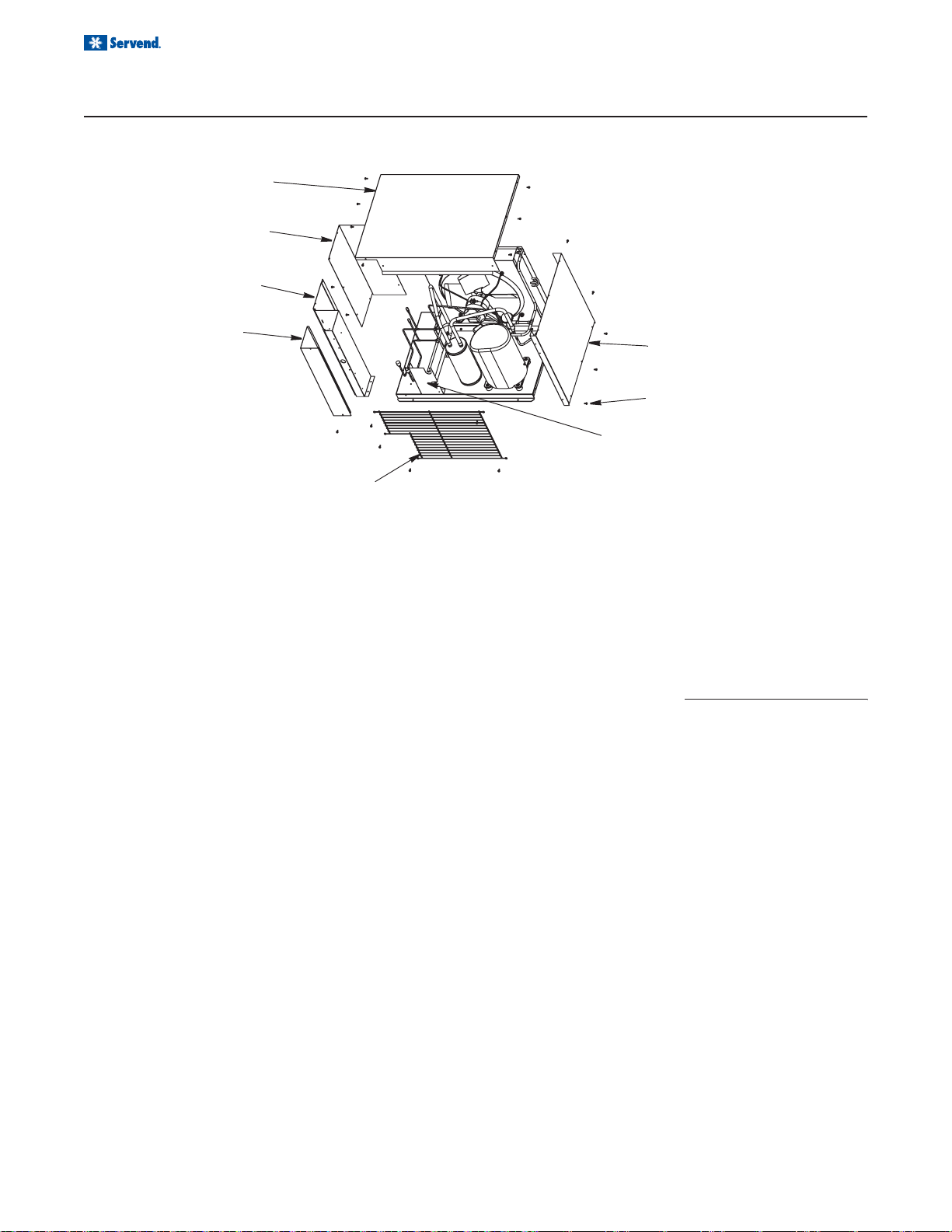
MANITOWOC® SU1024YC ICEMAKER
CVD1075 CONDENSING UNIT PANELS
5
4
3
2
1
6
8
7
PT1287
DESCRIPTION PART NUMBER
1 Condenser Fan Guard . . . . . . . . . . . . . . . . . . . . . . . . . . . . . . . . . . . . . . . . . . . . . . . . . . . . . . . . . . . . . 34-0689-3
2 Control Box Cover . . . . . . . . . . . . . . . . . . . . . . . . . . . . . . . . . . . . . . . . . . . . . . . . . . . . . . . . . . . . . . . . 603477-1
3 Control Box Panel . . . . . . . . . . . . . . . . . . . . . . . . . . . . . . . . . . . . . . . . . . . . . . . . . . . . . . . . . . . . . . . . 603707-1
4 Left Side Panel. . . . . . . . . . . . . . . . . . . . . . . . . . . . . . . . . . . . . . . . . . . . . . . . . . . . . . . . . . . . . . . . . . . 603729-1
5 Cover Top. . . . . . . . . . . . . . . . . . . . . . . . . . . . . . . . . . . . . . . . . . . . . . . . . . . . . . . . . . . . . . . . . . . . . . . 603475-1
6 Right Side Panel . . . . . . . . . . . . . . . . . . . . . . . . . . . . . . . . . . . . . . . . . . . . . . . . . . . . . . . . . . . . . . . . . 603470-1
7 Bracket. . . . . . . . . . . . . . . . . . . . . . . . . . . . . . . . . . . . . . . . . . . . . . . . . . . . . . . . . . . . . . . . . . . . . . . . . 604226-1
Miscellaneous Brackets, Screws, etc.
8 Screw, #10-24 x .50 Hex . . . . . . . . . . . . . . . . . . . . . . . . . . . . . . . . . . . . . . . . . . . . . . . . . . . . . . . . . . . 52-0206-9
Refer to Cross Reference Guide
44
Page 45

Installation and Service Manual
TROUBLESHOOTING
PROBLEM POSSIBLE CAUSE CORRECTIVE ACTION
Pump will not run but
tank appears to be
always full.
Pump will not run but
tank level appears to
be below start level.
Pump motor does not
shut off.
Black and/or red probe shorted
Problem with motor or motor wiring
Problem with Liquid Level Control
Board.
Common Lead (Green) shorted out to
Red wire (High Probe)
Common Lead (Green) shorted out to
Black wire (Low Probe)
Problem with Liquid Level Control
Board
Probe Harness Connection may be
open.
Water may not be reaching top probe
in carb tank.
Remove probes and bend straight or replace with new
probe(s)
Check line voltage first. Check AC voltage across
load terminals on Liquid Level Control. If voltage is
120 plus or minus 10%, replace motor or motor wiring.
Check line voltage first. If AC voltage across load
terminals is not 120 plus or minus 10%, replace the
Liquid Level Control Board.
Verify Green and Red wires are not touching.
Verify Green and Black wires are not touching.
Short the "H & L" terminals on the Liquid Level Control
Board. If motor does not shut off, replace Liquid Level
Control Board.
Verify connections are good or replace the wiring
harness.
Verify tank is not filled with CO
valve up and letting air escape until water comes out.
or air by pulling relief
2
Pump motor
intermittent
High Lead (Red) open or not
connected.
Common lead (Green) open or not
connected.
Problem with probe or probe harness.
Problem with motor or motor wiring.
Verify Red lead wire is connected from tank to unit.
Verify Green lead wire is connected from tank to unit.
Check motor and motor wires by removing red and
black wires from the Liquid Level Control Board. If
okay, short "H & L" terminal on Liquid Level Control
Board. If motor stays off, verify probes and bend
straight or replace. Verify with meter.
Measure AC voltage across load terminals on Liquid
Level Control Board. If line voltage is 120 plus or
minus 10% replace motor or motor wiring.
45
Page 46

Installation and Service Manual
TROUBLESHOOTING
PROBLEM POSSIBLE CAUSE CORRECTIVE ACTION
Pump motor intermittent Problem with Liquid Level Control
Board.
Pump motor starts and
stops, short cycles, as soon
as water level drops below
Red (High) probe.
Pump motor starts and
stops, short cycles, as soon
as water level drops below
Black (Low) probe.
Pump short cycles from
below high probe to just
above high probe - Low
probe has no effect.
Black (Low) Lead wire is open or
disconnected.
Red and Black Leads are switched with
each other.
Red and Green Leads are switched with
each other.
Black and Green Leads are switched
with each other.
Check li ne voltage first. If AC voltage across
load terminals on Liquid Level Control Board is
not 120 plus or minus 10%, replace the Liquid
Level Contorl board.
Verify connections and continuity of black wire
from Liquid Level Control Board to Probes on
Carb Tank.
Verify Red Lead is going to Red probe and
Balck Lead is going to Black probe.
Verify Red Lead is going to Red Probe and
Green Lead is going to Ground Screw on tank
Verify Black Lead is going to Black Probe and
Green Lead is going to Ground Screw on tank.
46
Page 47

Installation and Service Manual
47
Page 48

Installation and Service Manual
48
Page 49

Installation and Service Manual
49
Page 50

INDEX
A
agitation ........................... 15, 16
agitation cycle ......................... 16
Agitator Motor ......................... 37
Ambient ................................... 10
Auger ........................ 21, 30, 36
Auger Drive ............................. 33
auger motor ............................ 21
Auger Transition............... 23, 38
Auger tube ....................... 21, 23
Auto Bag Selectors ................. 18
B
B-I-B connectors ....................... 8
Back Room Package .............. 19
Bag-In-Box .......... 18, 19, 24, 25
Beverage Cooling ................... 16
Beverage System ................... 24
beverage tube ......................... 15
beverage valve ....................... 16
BIB pressure gauge ................ 19
Bin ........................................... 39
Bin Liner .................... 16, 21, 23
bracket .................................... 23
C
Carb Pump .............................. 35
Carbon Dioxide .................. 6, 20
Carbonated ............................. 10
Carbonation ............................ 20
Carbonator ...................8, 19, 20
carbonator tank ....................... 20
Carbonator Water pump ......... 19
CAUTION ................................ 23
Check List ................................. 8
claims ...................................... 14
clamps ....................................... 8
Cleaning .................................. 24
CO2 ................................ 7, 9, 20
CO2 cylinder ........................... 19
CO2 monitors ............................ 7
Cold Carb ................................ 10
Cold Plate ........................ 16, 23
Components ........................... 20
Condensing Unit .............. 43, 44
conductivity probes ................. 20
Control Box ............................. 40
Conversion .............................. 10
counter ...................................... 8
Covers ..................................... 27
cube ice .................................. 14
Cuber ............................... 28, 34
CVD® ...................................... 10
CVD1075 ......................... 43, 44
D
damage .............................. 3, 14
delivery ............................... 3, 14
Diagrams ................................ 27
diffusers ........................... 20, 22
disassemble ............................ 21
dispense point ......................... 16
dispenser ..................... 8, 15, 23
Dispensing .............................. 14
dispensing valves ................... 22
Distributor ................................. 3
door ......................................... 23
door lock ................................. 16
Drain .................................. 8, 30
drain pan .......................... 23, 28
drains ........................................ 8
drink tower .............................. 15
drive motor .............................. 15
ducts ......................................... 8
dynamic pressure ................... 19
E
Electric Box ............................. 38
electric motor .......................... 20
electrical box ........................... 20
Equipment ............................... 15
Evaporator .............................. 40
Exploded Views ...................... 26
exterior .................................... 22
External Carbonator tank ........ 19
F
fittings ...................................... 20
FOREWORD ............................ 3
G
gear motor .............................. 16
guidelines .................................. 9
H
health department ................... 22
hoses ...................................... 15
I
Ice ........................................... 14
Ice Agitation ............................ 16
ice chute .......................... 21, 23
ice dispenser ........................... 15
ice storage ....................... 15, 16
Icemaker .......................... 10, 40
Inspection .......................... 3, 14
INSTALLATION ......................... 8
Installation Date ........................ 3
Instructions ............................. 22
Internal Carbonation ............... 20
irregularities .............................. 3
K
key switch ............................... 22
L
liquid level control ................... 20
local code .................................. 9
location .............................. 8, 19
lock .......................................... 23
low probe ................................ 20
M
Maintenance 21, 22, 23, 24, 25
Manitowoc Beverage Equipment3
MANITOWOC® ...................... 10
MBE .......................................... 3
MBE Distributor ......................... 3
micro switch ............................ 16
mixing ratio ............................. 16
Model Number .......................... 3
modifications ............................. 6
Monthly Cleaning .................... 23
motor ................................ 19, 20
N
non-carbonated ....................... 10
nozzles ............................. 20, 22
nylon washer ........................... 20
O
Oetiker ...................................... 8
Operation ........................... 6, 20
OVERVIEW ............................. 14
P
paddle wheel ........................... 16
Panels .............................. 27, 44
Parts ........................................ 27
periodic agitation ..................... 16
PLUMBING ............................. 13
Power outlet .............................. 8
Pre-installation .......................... 8
pre-plumbed ............................ 20
pressure gauge ....................... 10
Primary pressure regulator ..... 19
probes ..................................... 20
pump ......................... 18, 19, 20
pump deck .............................. 19
Q
Qualified Service Personnel ..... 6
QuietQube® ............................ 10
R
rack ........................................... 8
red probe ................................ 20
refrigerant lines ....................... 15
Refrigeration .................... 41, 42
regulations .............................. 22
Relocation ................................. 6
Rocking Chute ................. 16, 36
rotary vane pump .................... 20
S
SAFETY ............................... 6, 7
sanitizing ............................ 7, 23
Secondary pressure regulator 19
Serial Number ........................... 3
Service Agent ............................ 3
service assistance .................... 3
Service Personnel ..................... 6
Shipping .................................... 6
Shipping, Storage, Relocation .. 6
soapy water ...................... 22, 23
soda water .............................. 16
solvents ................................... 23
Specifications ................... 17, 18
splash panel ....................... 7, 28
spout ................................ 21, 23
start-up ...................................... 6
Storage ..................................... 6
SU1024YC ....................... 10, 40
Super Cooled .......................... 14
syrup ................................ 16, 18
syrup boxes ............................... 8
Syrup Connections ................... 9
Syrup pump ............................ 19
T
TABLE OF CONTENTS ............ 5
tap water ................................. 20
Telephone Number ................... 3
transition ................................. 23
TROUBLESHOOTING ............ 45
tubes ....................................... 16
tubing ........................................ 8
U
Unit Inspection ........................ 14
UNPACKING ............................. 3
V
valve ................................. 13, 16
Valve Mount Cap .................... 37
valve nozzles .......................... 20
W
Warning ..................................... 6
WARRANTY ............................. 3
water ......................... 16, 19, 20
Water Connections ................... 9
water inlet ................................ 20
Water line .................................. 8
water pressure ........................ 20
water pump ............................. 20
water-to-syrup ratio.
Wiring ...................................... 26
See
brixing
Page 51

Installation and Service Manual
51
Page 52

Manitowoc Beverage Equipment
2100 Future Drive Sellersburg, IN 47172-1868
Tel: 812.246.7000, 800.367.4233 Fax: 812.246.9922
www.manitowocbeverage.com
In accordance with our policy of continuous product development and
improvement, this information is subject to change at any time without notice.
5013486 May 17, 2007 REV5
 Loading...