

Page 1
# 26 4331
©
Copyright by MULTIPLEX Modellsport GmbH & Co. KG 2015 Version 1.0
RR
# 21 4331
Page 2

Safety Information for MULTIPLEX model aircraft
This model is NOT A TOY in the usual sense of the term.
By operating the model the owner af! rms that he is aware of the content of the operating instructions, especially those
sections which concern safety, maintenance, operating restrictions and faults, and is capable of ful! lling these requirements.
This model must not be operated by any child under fourteen years of age. If a person below this age operates the model
under the supervision of a competent adult who is acting as the child’s guardian within the legal sense of the term, this
individual is responsible for the implementation of the information in the OPERATING INSTRUCTIONS.
THE MODEL AND ASSOCIATED ACCESSORIES MUST BE KEPT OUT OF THE REACH OF CHILDREN UNDER THREE
YEARS OF AGE" MODELS CONTAIN SMALL DETACHABLE PARTS WHICH MAY BE SWALLOWED BY CHILDREN
UNDER THREE YEARS. CHOKING HAZARD"
All the warnings in the OPERATING INSTRUCTIONS must be observed whenever the model is operated. Multiplex
Modellsport GmbH & Co. KG accepts no liability for loss or damage or any kind which occurs as a result of incorrect
operation or misuse of this product, including the accessories required for its operation. This includes direct, indirect,
deliberate and accidental loss and damage, and all forms of consequent damage.
Every safety note in these instructions must always be observed, as all the information contributes to the safe operation of your model. Use your model thoughtfully and cautiously, and it will give you and your spectators many hours of
pleasure without constituting a hazard. Failure to operate your model in a responsible manner may result in signi! cant
property damage and severe personal injury. You alone bear the responsibility for the implementation of the operating
instructions and the safety notes.
Approved usage
The model is approved exclusively for use within the modelling hobby. It is prohibited to use the model for any other
purpose than that stated. The operator of the model, and not the manufacturer, is responsible for damage or injury of
any kind resulting from non-approved use.
The model may only be operated in conjunction with those accessories which we expressly recommend. The recommended components have undergone thorough testing, are an accurate match to the model, and ensure that it functions
safely. If you use other components, or modify the model, you operate it at your own risk, and any claim under guarantee
is invalidated.
To minimise the risk when operating the model, please observe the following points:
l The model is guided using a radio control system. No radio control system is immune to radio interference, and
such interference may result in loss of control of the model for a period of time. To avoid collisions, you must
therefore ensure at all times that there is a wide margin of safety in all directions when operating your model. At
the slightest sign of radio interference you must cease operating your model"
l Never operate your model until you have successfully completed a thorough check of the working systems, and
carried out a range-check as stipulated in the instructions supplied with your transmitter.
l The model may only be # own in conditions of good visibility. You can avoid being temporarily blinded by not # ying
towards the sun, or in other dif! cult light conditions.
l A model must never be operated by a person who is under the in# uence of alcohol, drugs or medication which
have an adverse effect on visual acuity and reaction time.
l Only # y your model in conditions of wind and weather in which you are able to maintain full control of the model.
Even when the wind is light, bear in mind that turbulence can form at and around objects which may have an
effect on the model.
l Never # y in any location where you may endanger yourself of others, e.g. close to residential areas, overhead
cables, open roads and railway lines.
l Never # y towards people or animals. You may think that # ying low over other people’s heads is proof of your
piloting skill, but all it does is place others at unnecessary risk. It is in all our interests that you let other pilots
know that this is what you think. Always # y in such a way that you do not endanger yourself or others. Bear in
mind that even the best RC system in the world is subject to outside interference. No matter how many years of
accident-free # ying you have under your belt, you have no idea what will happen in the next minute.
GB
Page 3

Residual risks
Even if the model is operated in the correct manner, and you observe all safety aspects, there is always a certain residual
risk.
For this reason it is mandatory to take out third-party liability insurance. If you join a club or fl ying association, insurance
is usually available or included in the annual fee. Make sure that your insurance cover is adequate (i.e. that it covers
powered model aircraft). Always keep your models and your radio control equipment in perfect order.
The following hazards may occur owing to the model’s construction and type:
l Injury caused by the propeller: you must keep well clear of the area around the propeller from the moment that
the battery is connected. Please bear in mind that objects in front of the propeller may be sucked into it, and
objects behind the propeller may be blown away by it. The model may start moving when the propeller starts
to turn. You must therefore position the model in such a way that it cannot move towards other persons if the
motor should unexpectedly start running. When you are carrying out adjustment work involving the running
motor
, you must ensure that the model is always held securely by an assistant.
l Crash caused by pilot error: this can happen even to the best of pilots, so it is essential to fl y exclusively in a
safe environment: an approved model fl
ying site and suitable insurance are basic essentials.
l Crash caused by technical failure or unnoticed damage in transit or in the workshop. A thorough check of the
model before every fl
ight is essential. However
, you should also take into account at all times that material
failures can and do occur
. Never fl y in a location where your model may damage or injure others.
l Keep within the stated operating limits. Excessively violent fl ying will weaken the airframe, and may result in
sudden material failure, or may cause the model to crash during a subsequent fl
ight due to “creeping” conse-
quent damage.
l Fire hazard caused by electronic failure or malfunction. Store batteries safely, and always observe safety
notes which apply to the airborne electronic components, the battery and the battery charger
. Protect all elec-
tronic equipment from damp. Ensure that the speed controller and battery are adequately cooled.
The instructions which accompany our products must not be reproduced and / or published, in full or in part, in
print or any electronic medium, without the express written approval of Multiplex Modellsport GmbH & Co. KG.
GB
Page 4

Examine your kit carefully!
MUL
TIPLEX model kits are subject to constant quality checks throughout the production process, and we sincerely
hope that you are completely satis! ed with the contents of your kit. However, we would ask you to check all the parts
before you start construction, as we cannot exchange components which you have already worked on. If you ! nd
any part is not acceptable for any reason, we will readily correct or exchange it. Just send the component to our Model
Department. Please be sure to include the purchase receipt and a brief description of the fault.
We are constantly working on improving our models, and for this reason we must reserve the right to change the kit
contents in terms of shape or dimensions of parts, technology, materials and ! ttings, without prior noti! cation. Please
understand that we cannot entertain claims against us if the kit contents do not agree in every respect with the instructions and the illustrations.
Caution!
Radio-controlled models, and especially model aircraft, are by no means playthings. Building and operating them
safely requires a certain level of technical competence and manual skill, together with discipline and a responsible attitude at the fl ying fi eld. Errors and carelessness in building and fl ying the model can result in serious
personal injury and damage to property. Since we, as manufacturers, have no control over the construction,
maintenance and operation of our products, we are obliged to take this opportunity to point out these hazards
and to emphasise your personal responsibility.
Warning:
Like every aeroplane, this model has static limits. Steep dives and senseless manoeuvres inappropriate to the type
may result in the loss of the aircraft. Please note: we will not replace the model in such cases. It is your responsibility to
approach the airframe’s limits gradually. It is designed for the power system recommended in these instructions, but is
only capable of withstanding the " ight loads if built exactly as described and if it is in an undamaged state.
Recommended equipment:
2x Li-BATT FX 3/1-3200 (M6) (KIT+RR)
Item number: # 157371
1x FunCub XL power set (KIT) Item number: # 332610
1x RX-7-DR light M-LINK 2.4 GHz receiver (KIT+RR) Item number: # 55810
6x HS 225 BB servo (KIT) Item number: # 112225
2x Servo extension lead, 600 mm (KIT) Item number: # 85032
4x Servo extension lead, 300 mm (KIT) Item number: # 85031
2x Servo extension lead, 150 mm (KIT) Item number: # 85019
1x Zacki ELAPOR 20 g (RR) Item number: # 852727
2x Zacki ELAPOR 20 g (KIT) Item number: # 852727
Optional equipment:
FunCub XL " oats set Item number: # 733098
Alfred parachutist Item number: # 852004
POWER-MULTIlight, 5 LEDs Item number: # 73030
RX-12-DR compact M-LINK 2.4 GHz receiver Item number: # 55821
HS-225 BB servo for aero-tow release Item number: # 112225
HS-225 BB servo for jettison bay Item number: # 112225
Royal SX transmitter Item number: # 3540 0/1/2/3
MULTIcharger LN-3008 EQU combo with AC/DC mains PSU, 230 V Item number: # 92545
Charge lead (M6) for MULTIcharger LN-3008 EQU Item number: # 92516
GB
Page 5

Important note
This model is not made of Styrofoam™, and it is not possible to glue the material using white glue, polyurethane or
epoxy; these adhesives only produce super! cial joints, and simply break away under stress. Please be sure to use
medium-viscosity cyano-acrylate glue exclusively, preferably Zacki ELAPOR® # 59 2727, which is optimised specifi cally
for ELAPOR® particle foam. If you se Zacki ELAPOR® there is usually no need for cyano ‘kicker’ or activator. However,
if you wish to use a different adhesive which requires the use of activator, please note that these materials are injurious
to health, and should always be applied in the open air. Take care when handling all cyano-acrylate adhesives, as they
harden in seconds, so don’t get them on your fi ngers or other parts of the body. We strongly recommend the use of
goggles to protect your eyes. Keep the adhesive out of the reach of children! For certain joints it is also possible to use
hot-melt adhesive; the instructions indicate where this is the case.
Working with Zacki ELAPOR®
Zacki ELAPOR® has been developed specifi cally for glued joints in our models which consist of moulded ELAPOR®
foam parts.
Please observe the following points in order to obtain perfect joints:
• Avoid the use of activator. ‘Kicker’ signifi cantly weakens the joint. We advise leaving joined parts for 24 hours to obtain
maximum strength, particularly when the glued area is large.
• Activator should only be used for temporary, small-area joints (‘tacking’). Spray a little activator on one surface, and
allow it to air-dry for about thirty seconds.
• To obtain maximum joint strength you should lightly sand the surface with 320-grit abrasive paper before applying glue.
Bent parts - actually don’t exist. If you fi nd that a component has taken up a curve, perhaps after being transported, it is easy to straighten again. In this respect ELAPOR® behaves in a similar way to metal: bend the
component back slightly beyond the correct position, and the material will then spring back to its proper shape
when released, and maintain it. There are limits, however - don’t overdo it!
Bent parts - really do exist. If you wish to paint your model, apply MPX Primer # 60 2700 to the surfaces, wiping it on
very lightly as if you were cleaning the model. Paint must always be applied thinly and evenly, otherwise the component
will warp. Then you really will have bent parts, and they will also be heavy and perhaps even unusable. We have found
that matt-fi nish paints produce the best visual effect.
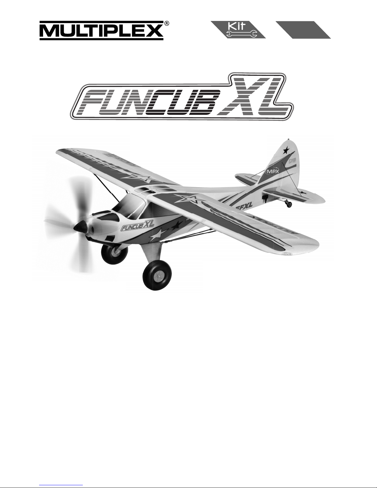
Technical information FunCub XL:
Wingspan: 1700 mm
Overall length: 1200 mm
All-up weight: 2850 g
Total surface area: 51 dm²
Wing loading: 56 g/dm²
Channels: 7-
10
RC Functions:
Rudder, elevator, ailerons, landing fl aps, throttle optional aero-tow release, optional load bay,
optional navigation lights and landing light
Flight time: ca. 6 min (6S ~3300Ah)
Note: please remove the pictures from the center of the instructions!
Page 6

Congratulations on your new FunCub XL!
Y
ou will need the following tools to build the model:
• 2 x Zacki Elapor
# 85 2727
• Hot-glue gun
• Cross-point screwdrivers, large and small
• Balsa knife
• Pointed-nose pliers
• Allen key, 1.5 mm A/F
• 6 mm A/F open-ended spanner
• 10 mm A/F open-ended spanner
• 13 mm A/F open-ended spanner
•
Additional items required if you intend to install the POWER-MULTIlight:
• 2 M6 plug # 8 5213
• 2 M6 sockets # 8 5214
• Soldering iron
• Solder
Before starting construction:
Please check that the kit contents are complete by comparing
the parts supplied with the Parts List on page 31 Figs. 01 & 02
1. Preparing the fuselage shells, installing the servos (KIT)
Locate the pre-assembled M-Frame 30 and glue it in the right-hand
fuselage shell 5 using Zacki. Now glue the M-Frame " oats support
31, the two clip hinges “A” 71, the Canopy Lock clip 73 and the
aero-tow coupling 75 in the appropriate positions.
Figs. 03 + 04
Glue the second Canopy Lock clip 73 in the left-hand fuselage
shell 4 in the same way.
Centre the elevator servo (HiTec HS-225BB # 11 2225) from your
transmitter, then fi x the output lever on the servo output shaft.
The lever should point left when the inscription on the servo label
is the right way up (legible). Fit the retaining screw. Connect the
servo to the 600 mm extension lead (# 8 5032), and apply a little
adhesive tape around the connectors to prevent the plug working
loose in fl ight. Fit the elevator servo in the opening in the righthand fuselage shell 5, with the cable facing forward, and secure
it with hot-melt glue at both mounting lugs.
Fig. 05
Install the rudder servo (HiTec HS-225BB # 11 2225) as described
for the elevator servo - but with the output lever facing in the opposite direction. Connect it to a 600 mm extension lead (# 8 5032)
and secure it with tape, then glue the servo in the opening in the
left-hand fuselage shell 4.
Fig. 06
2. Joining the fuselage shells, attaching the external parts
(KIT)
Before joining the fuselage shells 4 + 5 permanently, fi t them together “dry” (without glue), and check that everything fi ts correctly.
When you are satisfi ed, apply Zacki to the joint surfaces of one
fuselage shell, and glue the two mouldings together.
Figs. 07 + 08
Now glue the dummy air outlets 24 + 25, the upper cowl fairings
26 + 27 and the fuselage facing ribs “L” 76 and “R” 77 in the
positions shown.
Figs. 09 + 10
Invert (turn over) the fuselage and glue the “rear” exhaust fairing
29
to
the underside of the fuselage. Glue the cargo door supports
“A” 32 and “B” 33 in place, followed by the tailwheel support 56.
Figs. 11 + 12
3. Completing the cowl and canopy (KIT)
Take the moulded cowl 7 and glue the “front” exhaust fairing 28
to the underside using Zacki.
Figs. 13 + 14
The cowl is fi xed to the fuselage using magnets. Glue three of
the magnets 34 in the moulded-in recesses in the cowl 7, and
the remaining three to the recesses in the front of the fuselage.
!CAUTION!: it is important to fi t the magnets the right way
round,
i.e.
the pairs of magnets which come into contact with each
other
m
ust attract - not repel! Do not place the cowl on the fuselage unti
l
the glue has set hard!
Figs. 15 - 17
Now
glue the two Canopy Lock lugs 74 in the moulded slots in
the canopy 6 using Zacki.
Fig. 18
4. Installing the motor (KIT)
Screw the metal cruciform motor mount to the motor using the four
cross-head screws supplied. Apply a drop of thread-lock fl uid to
each screw, and tighten them fi rmly.
Fig. 19
Remove the cowl from the fuselage before installing the motor.
This is the procedure: place the plastic cruciform motor mount 131
between the metal cruciform mount (attached to the motor) and the
motor bulkhead (part of the M-Frame). Fix the motor assembly in
place using the four M3 x 12 mm retaining screws 132 and 3 mm
I.D. washers 133. The cowl can now be replaced on the fuselage.
Figs. 20 + 21
5. Installing the main undercarriage (KIT+RR)
First fi x the angle strut brackets 36 to the underside of the main
undercarriage unit 35 using two M3 x 6 mm cross-head screws 37
on each side. The fi rst main wheel 39 can now be attached to the
main undercarriage unit using the axle 40 (M6 x 45 mm machine
screw)
and one M6 self-locking nut 41 on each side. Ensure
that
the wheel is still free to rotate smoothly when you have tightened
the nuts. Repeat the procedure on the other side of the main
undercarriage.
Fig. 22
When the undercarriage is complete, fi x the assembly to the
M-Frame using four M3 x 20 mm retaining screws 42. Note that
the strut retaining brackets must be at the rear (towards the tail)!
Fig. 23
6. Installing the tailwheel unit (KIT+RR)
The fi rst step in assembling the tailwheel unit 47 is to slip the lower
bush 48
through
the hole from the underside. Fit the upper
bush
46 on top, and glue these parts together with a little Zacki. The
tailwheel spigot 49 can now be slipped through the bush from the
underside.
The spigot is secured with the steering lever 44: fi t
an
M3 x 6 mm cross-head screw 45 in the shaft driver 43 which fi ts
in
the steering lever 44. Ensure that the screw engages on
the
machined area of the spigot.
The
bottom end of the spigot is bored and threaded M3. Fit the
tailwheel yoke 50 on the spigot, engaging the square section in
the hole, and fi t an M3 x 10 mm cross-head screw 55 and a 3 mm
I.D. washer 54 to secure it. Tighten the screw fi rmly.
Now fi t the tailwheel 51 and tailwheel shaft 52 (M2 x 22 mm
)
between
the wheel and the tailwheel bracket, together with
two
M2.5 nuts 38 (as spacers), and secure the wheel with the M2
self-locking nut 53
.
Fig. 24
Page 7

The tailwheel assembly should now be attached to the tailwheel
support 56 in the fuselage using the two M3 x 20 mm retaining
screws 57.
Fig. 25
7.
Completing the wings (KIT)
Glue one tubular carbon ! bre spar 123/124 in the channel in each
of the wing panels 8 and 9. Any excess glue which is squeezed
out should be wiped away using a paper towel, otherwise there is
a danger that the spar cover will not ! t " ush.
Glue the rear spar covers 12 and 13 in place, taking care to avoid
glue running inside them. At this stage we turn to the landing " aps
14 and 15: clip the offset hinge components 64 and 65 together,
and the " ap horn components 63 and 64. Glue the offset hinges
and horns in the appropriate recesses in the wings and " aps.
Fig. 27 + 28
The strut brackets 98 can now be glued to the wings. Glue the
horns 61 to the ailerons at the same time.
Figs. 29 + 30
Set the aileron servos (HiTec HS-225BB # 11 2225) to centre
from the transmitter, ! t the output arms on them, and secure the
arms with the retaining screws provided. Place the servos in the
recesses in the wings, and secure them with a little hot-melt glue
applied to the mounting lugs. Attach the swivel pushrod connectors
66 to the aileron horns 61, together with the 2 mm I.D. washers
69 and M2 nuts 70; ensure that the swivel barrel rotates smooth-
ly, but without any trace of lost motion. When you are satis! ed,
secure the nuts 70 with a drop of Zacki. Connect the servo lead
to the 150 mm extension lead # 8 5019 and press the cable into
the channel in the wing.
The servos can now be connected to the aileron horns using
the metal pushrods 114. With the servos and ailerons at centre
(neutral), tighten the M3 x 3 mm grubscrews 68 in the connector
barrels; tighten them ! rmly.
Figs. 31 + 32
Connect the " ap servos to the receiver, and run them to the ‘retracted’ end-point from the transmitter. Fit the output lever on the
servo in such a way that the metal " ap pushrod 117 is exactly in
line with the servo output arm when the landing " ap is at neutral,
as shown in Fig. 33; the servo is not under stress in this position.
Attach the swivel pushrod connector, consisting of parts 66 and
68 - 70, to the " ap horn as described in the preceding step, and
connect the pushrod 117 as shown in Fig. 34. Check the " ap
linkages repeatedly until you are con! dent that they work reliably,
then apply a little hot-melt glue to the servo lugs to ! x the servos
in the wing recesses. Allow the glue to set hard, then tighten the
M3 x 3 mm grubscrews 68 ! rmly.
Figs. 33 - 35
8. Installing the POWER-MULTIlight lighting system in the
wings (KIT+RR)
The FunCub XL is designed to accept the POWER-MULTIlight
system # 7 3030. Cables are already present in the wings of the
RR version.
Place one white LED on the wing at the landing light position, lay
the cable on the wing surface along the line of the cable duct, and
cut it off at a point about 10 cm past the root rib; this leaves spare
cable for soldering to a central M6 plug.
If you wish to keep the option of ! tting a lighting system at a later
date, we recommend that you install cables, or cords for pulling
cables through the structure, at this stage.
The best method of securing the LED is to apply a drop of Zacki.
If the LED is now in the correct position - or if you don’t intend to
! t a lighting system - the next step is to ! x the clear LED landing
light cover 96 to the wing by applying a little glue to its edges.
Fig. 36
The anti-collision lights and the " ashing lights on the underside
of the wings are installed using the same basic procedure as
described for the landing lights. Glue the lamp brackets 95 to the
wingtips as shown. Screw the navigation light covers 93 + 94 to
the brackets 95 using the 1.7 x 14 mm screws 97.
Fig. 37
9. Completing the wing wiring (KIT+RR)
Glue the connector box frames 82 + 83 in the wings, and deploy
the cables as shown in Fig. 39.
The front spar covers 10 + 11 can now be glued in the recess in
the underside of the wings
Fig. 40
Glue the connector supports 86 + 87 in the frames 82 + 83 using
a small amount of Zacki, as shown in Fig. 41. Now lay the lighting
system cables and the connectors on the support, and ! x the connector clamp 88 over the top, securing it with the screws 90 (2.4 x
8 mm). The plugs must be clamped in a de! ned position as shown.
Figs. 41 + 42
Solder an M6 plug to the lighting cables at a point about 5 cm from
the wing root rib, and apply hot-melt glue all round the soldered
joints to seal them, so that no bare contacts are exposed. Alternatively you can use heat-shrink sleeves to insulate the joints. Take
care when assigning the wires to the connector pins in the wing and
the fuselage: please ensure that the correct LEDs are connected.
!Caution!: the LEDs of the POWER-MULTIlight system operate
on different voltages and " ashing sequences, so it is not possible
to connect together the positive (+) and negative (-) wires.
Figs. 43 + 44
Fit the covers 84 + 85 on the cable boxes, and secure them with
the 2.7 x 12 mm screws 91.
Figs. 45 + 46
10. Installing the wing retainer system (KIT)
Push an M5 nut 81 (M5) into each wing root ! tting 78 + 79, and
secure them with a drop of Zacki; take care to prevent glue running
into the threads. The wing root ! ttings can now be glued to the
wing roots as shown.
Figs. 47 + 48
11. Completing the wing struts (KIT)
Locate the two parts of the lower strut ! ttings 106 + 107, insert
the aluminium spigot 103, and secure the parts with the M2 x 8
mm screws 108 and M2 nuts 110. Please note that the arrows on
parts 106 and 107 must face forward. For the sake of appearance
the screws should be on the top surface.
Screw the strut end-piece 104 to the assembly. Slide the CFRP
main struts 111 into the open holes, and glue them securely using
Zacki. In the interests of safety an M2 x 6 mm screw 109 and an
M2 self-locking nut 110 should be ! tted between the carbon ! bre
struts as shown, to provide additional clamping pressure to the
strut ! tting.
Repeat the procedure to produce two sets of struts, remembering
to reverse the position of the screws and nuts.
Fig. 49
Fix the ball-links 100 to the strut brackets in the wings using the
M2 x 8 mm screws 101 and M2 nuts 102. Note that the linkage
balls should face inwards, towards the centre of the wing.
Fig. 50
Fit the upper strut end ! ttings 99 on the CFRP struts ‘dry’ (no glue),
and clip them onto the linkage balls 100. Check that the ! ttings
99 are at the correct angle before gluing them permanently to the
CFRP strut tubes 111, ideally using thin Zacki. Take great care
not to let glue run onto the linkage balls$
Figs. 51 + 52
Page 8

12. Completing the tail panels (KIT+RR)
Glue the elevator ! tting 60 in the elevator 16. Apply a little glue
to the sleeves 112, slip them over the ends of the wire elevator
joiner 113, and glue this assembly in the elevator as shown. Glue
the elevator joiner cover 23 over the top, followed by the elevator
horn 61.
Glue
a hinge 92 at the outboard end of the tailplane on each
side,
a
nd glue the in-! ll pieces 16a and 16b over the top to conceal them.
Figs. 55 + 56
Glue the clip-hinges “B” 72 in the rudder 17, and glue the in-! ll
pieces 18 and 19 over the top. Glue the rudder horn 61 in place,
followed by the tailwheel driver 59.
Figs. 57 + 58
Slide the tailplane into the slot in the tail end of the fuselage ‘dry’
(no glue), and check that it sits at right-angles to the ! n. Before
gluing it in place, we recommend that you ! t the wings on the model
and sight along the fuselage from nose or tail to check alignment.
The tailplane can then be glued in place, and again checked for
alignment. Allow the glue to set hard, then clip the rudder hinges
into place: ! rst ! t the bottom hinge spigot, then engage the hinge at
the top. Glue the tailplane struts, consisting of parts 127 and 128,
to the tailplane, again taking care to maintain correct alignment.
Figs. 59 - 63
Attach two swivel connectors 66 to the tailwheel steering lever 44,
securing them with the 2 mm I.D. washers 69 and M2 nuts 70.
Connect the two tailwheel steering springs 58 to the tailwheel driver
59 on the rudder, and attach them to the steering lever 44 using
the M3 x 3 mm grubscrews 68; both springs should be under light
tension, and the tailwheel should line up correctly with the rudder.
Fig. 64
Connect the elevator pushrod 115 and the rudder pushrod 116 to
the servo output arms as shown in Figs. 65 and 66, and mount the
swivel connectors 66, the 2 mm I.D. washers 69 and the M2 nuts
70 on the control surface horns The nuts must be tightened just to
the point where the connector barrels rotate smoothly, but without
any hint of binding. Apply a drop of Zacki to these nuts when you
are satis! ed. Slip the pushrods through the swivel connectors,
set the servos and control surfaces to centre, and tighten the M3
grubscrews 68 ! rmly.
Figs. 65 + 66
13. Closing the cargo bay (KIT)
T
he FunCub XL is prepared as standard for ! tting a radio-controlle
d
cargo
drop bay. This is an optional feature, and can be retro-!
tted
a
t any time. If you do not wish to ! t working doors, simply close th
e
cargo
bay using the cargo bay bottom panel 22. which is
secured
with
four magnets 34: two are glued to the bottom panel, and
a
further two in the bottom of the fuselage.
CAUTION:
it is important to ! t the magnets the right way round,
i.e. the pairs of magnets which come into contact with each
other
must
attract - not repel" Do not place the bottom panel on
the
fuselage until the glue has set hard"
Figs. 67 - 70
14. Installing the cargo bay doors (KIT+RR)
First
take the left-hand cargo bay door 20, and glue a magnet 34
in the recess as shown. Glue the square-section CFRP stif
fening
rod 129 (2 x 2 x 188 mm) in the long slot.
Fig. 71
G
lue the tubular bush 122 for the L-shaped hinge pin 121 adjacent
to the horn recess using Zacki; please take great care to avoid
adhesive running inside the tube" The L-shaped pin is set upright,
and pushed forward later when the door is ! tted. The door is locked
in place by folding the L-shaped pin down until the magnet traps it.
Glue the ! xed pivot pin 120 in the channel at the other end of the
bay door as shown. The actuating horn 62 can also be glued in
place at this stage. Note that the linkage holes in the horn must
face the CFRP stiffening strip.
Repeat the procedure with the right-hand cargo bay door 21.
Figs. 72 - 76
The next step is to install the cargo bay doors themselves: turn the
fuselage over, resting on its back, and slip the rear, ! xed hinge pin
120 into the hole in the former. With the L-shaped pin 121 pulled
back, align the door carefully, then slide the hinge pin through the
sleeve and into the hole. It should then be possible to fold the pin
down, so that it is trapped by the magnet. Repeat the procedure
with the second cargo bay door.
Figs. 77 + 78
The servo which opens and closes the cargo bay doors needs to
be installed with the output shaft on the left-hand side, as seen
from the nose of the model. When the bay doors are open, the
servo output arm should be angled down by about 45° as shown.
The doors are actuated by means of two pushrods 118, one of
which is connected to the outer hole in the servo output arm, the
other to the next hole towards the centre.
Mount the swivel connectors 67 in the inner holes of the cargo bay
door horns. Slip the pushrods through the connector barrels, and
tighten the M3 x 3 mm grubscrews 68 to secure them.
Fig. 79
15. Installing the propeller and spinner (KIT+RR)
Fit
the taper collet 142 and the propeller driver 141 on the
motor
s
haft. Slide the lock washer 140 above, then slip the spinne
r
backplate 139
and the propeller 137 on the propeller driver.
Fit
the
8 mm I.D. spreader washer 137 and the retaining nut 136,
and
tighten
the nut lightly, so that you can still adjust the propeller’
s
position
relative to the spinner backplate. Position the propeller
,
the
backplate and the spinner cap 135 in such a way that
the
propeller
! ts neatly through the two cut-outs when the
spinner
cap
is pushed fully into place. Remove the spinner cap again
and
tighten
the propeller retaining nut fully. The spinner can now
be
replaced,
and secured with the M3 x 20 mm retaining screw 134.
Figs. 80 + 81
16. Installing the tow release servo (KIT+RR)
Place
the tow release servo (HiTec HS-225BB # 11 2225) in
the
a
ppropriate recess in the fuselage, with the output shaft on the lef
t
as
seen from the nose of the model. Fix the servo in place
with
hot-melt glue applied to the mounting lugs.
Connect
the pre-formed end (Z-bend) of the tow-release
pushrod
1
19 (1.5 x 62 mm steel rod) in the innermost hole of the
servo
o
utput arm as shown, then slip the free end of the pushrod throug
h
t
he tow release mechanism 75, and ! t the output arm on the serv
o
output
shaft, pointing horizontally to the left. Fit the output
screw
to retain the servo output arm.
Fig. 84
17.
Installing the POWER-MULTIlight system in the
fuselage
(KIT+RR)
The
! rst step here is to remove the dummy lamps on the
rudder
(rear
and top), using a sharp balsa knife to cut them off # ush
with
the
surface. Hollow out a little foam at these points so that
the
LED
and its cable ! t inside the rudder. Fix the LEDs in place
with
a
drop of Zacki, and press the cables into the slots in the rudder
.
Run
the cable forward through the cable duct, and plug it
into
the
Multilight control unit. The rear LED is white, and the top
one
(
beacon) is red. If you wish to install another LED on the undersid
e
of
the fuselage, we recommend ! tting it just aft of the cargo bay
,
forward of the #
oats support.
Fig. 85
Page 9

18. Installing the receiving system components (KIT+RR)
Plug all the servo leads into the receiver, and program the model
at the transmitter so that the control surface travels are as stated
(Point 19). The socket sequence for MULTIPLEX radio control
systems - assuming that you have not re-assigned the channels
- is as follows:
1. L.H. aileron
2. Elevator
3. Rudder
4.
Throttle
5. R.H. aileron
6. L.H. fl
ap
7. R.H. fl
ap
8.
Aero-tow release
9. Cargo bay doors
10. POWER-MUL
TIlight
Fix the receiver to the inside of the cabin window using hook-andloop tape. The tape will adhere more strongly to the ELAPOR®
surface if you apply a few drops of Zacki to the sticky surface fi rst.
19.
Assembling the model (KIT+RR)
Fit the wing joiner 125 through the fuselage facing ribs with
the
plastic
stop-piece 130 on the left-hand side. Slide the rear
spar
126
into one wing panel, and push that wing fully onto the
wing
joiner
. Take care not to allow the struts (attached to the wings)
to
damage the fuselage.
Push
the second wing fully into place, then secure both
wings
with
the two M5 x 15 mm retaining screws 80, fi tting them
through
the facing ribs.
Fig. 82
C
onnect the wing struts to the brackets on the undercarriage,
and push a folding spring bolt 105 through the strut fi tting and the
bracket on each side. Fold the spring bolts over to secure the struts.
Within certain limits it is possible to adjust the length of the struts
at the threaded ends. Make any adjustments required at this point,
to ensure that the wing is not under stress.
Fig. 83
20. Balancing (KIT+RR)
Fit
the fl ight battery and battery tray in the fuselage, and adj
ust
their
position until the model balances at the 85 mm point
(Centre
of
Gravity measured back from the wing leading edge close to
the
f
uselage). Secure the battery with the hook-and-loop tape 143 an
d
144 supplied, and the hook-and-loop strap 145.
T
o ensure that the tape adheres well to the bottom of the
fuselage
w
e recommend applying a few drops of Zacki to the sticky surface.
!CAUTION!: if you place a heavy payload, such as sweets, in
the
cargo
bay, the additional weight will move the model’s Centre
of
G
ravity further aft (back). If you intend to use the cargo bay, it is im-
portant to check the CG with the payload installed in the fuselage.
21. Recommended control surface travels (KIT+RR)
Rudder:
right / left 30 mm ~35°, approx. 40% Expo
Elevator: up 25 mm, down 12 mm, approx. 50% Expo
Aileron: up 13 mm, down 12 mm approx. 50% Expo
Landing fl aps: down 90°, down-elevator compensation approx. 4
mm, approx. 0.8 sec. delay
22. Safety
Safety is the First Commandment when fl ying any model aircraft.
Third party insurance is mandatory. If you join a model club,
suitable cover will usually be available through the organisation.
It is your personal responsibility to ensure that your insurance is
adequate (i.e. that its cover includes powered model aircraft). Make
it
your job to keep your models and your radio control system
in
perfect
order at all times. Check and observe the correct
charging
p
rocedure for the batteries you are using. Make use of all sensibl
e
s
afety systems and precautions which are advised for your system
.
An
excellent source of practical accessories is the MUL
TIPLEX
main catalogue or our website www.multiplex.de
MUL
TIPLEX products are designed and manufactured exclusively by active modellers for practising modellers. Always fl y with
a responsible attitude. You may think that fl ying low over other
people’s heads is proof of your piloting skill; others know better.
The real expert does not need to prove himself in such childish
ways. Let other pilots know that this is what you think too, as it is in
all our interests. Always fl y in such a way that you do not endanger
yourself or others. Bear in mind that even the best RC system in
the world is subject to outside interference. No matter how many
years of accident-free fl ying you have under your belt, you have
no idea what will happen in the next minute.
Before every fl ight, check that the battery, the wings and the
tailplane are attached and fi rmly seated. Check in turn that
each control surface is operating correctly!
We - the MULTIPLEX team - hope you have many hours of pleasure building and fl ying your new model.
MULTIPLEX Modellsport GmbH &Co. KG
Page 10

Parts List - FunCub XL # 214331
Part No. Qty Description Material Dimensions
1 1 Building instructions, KIT / RR
2 1 Complaints form, models
3 1 Decal sheet
4 1 L.H. fuselage shell Foam Ready made
5 1 R.H. fuselage shell Foam Ready made
6 1 Canopy Foam Ready made
7 1 Cowl Foam Ready made
8 1 L.H. wing Foam Ready made
9 1
R.H. wing
Foam Ready made
10 1
Front L.H. spar cover
Foam Ready made
11 1
Front R.H. spar cover
Foam Ready made
12 1
L.H. rear spar cover
Foam Ready made
13 1
R.H. rear spar cover
Foam Ready made
14 1 L.H. landing fl
ap
Foam Ready made
15 1 R.H. landing fl
ap
Foam Ready made
16 1 T
ailplane Foam
Ready made
16a 1 L.H. Tailplane in-fi
ll piece
Foam Ready made
16b 1 R.H. Tailplane in-fi
ll piece
Foam Ready made
17 1
Rudder Foam
Ready made
18 1 Upper rudder in-fi
ll piece
Foam Ready made
19 1 Bottom rudder in-fi
ll piece
Foam Ready made
20 1
L.H. cargo bay door
Foam Ready made
21 1
R.H. cargo bay door
Foam Ready made
22 1
Cargo bay bottom panel
Foam Ready made
23 1 Elevator j
oiner cover
Foam Ready made
24 1
L.H. dummy air outlet
Foam Ready made
25 1
R.H. dummy air outlet
Foam Ready made
26 1
L.H. upper cowl fairing
Plastic Ready made
27 1
R.H. upper cowl fairing
Plastic Ready made
28 1
Front exhaust fairing
Plastic Ready made
29 1
Rear exhaust fairing
Plastic Ready made
30 1
M-Frame W
ood Ready made
31 1 M-Frame fl
oats support
Wood Ready made
32 1 Cargo door support A Foam Ready made
33 1
Cargo door support B
Foam Ready made
34 12 Cowl / cargo bay magnet Metal 10x5x2mm
35 1 Main undercarriage unit Aluminium Ready made
36 2 Angle strut bracket Aluminium Ready made
37 4 Screw Metal M3x6mm
38 2 Nut Metal M2.5
39 2 Main wheel Plastic / rubber 126mmØ
40 2 Wheel axle (machine screw) Metal M6x45 mm
41 4 Self-locking nut for axle Metal M6
42 4 Undercarriage retaining screw Metal M3x20 mm
43 1 Tailwheel shaft driver Metal Ready made
44 1 Tailwheel steering lever Plastic Ready made
45 1 Cross-head screw Metal M3x6 mm
46 1 Upper tailwheel bush Ready made
47 1 Tailwheel unit Aluminium Ready made
48 1 Lower tailwheel bush Plastic Ready made
49 1 Tailwheel spigot Ready made
Page 11

50 1 Tailwheel yoke Aluminium Ready made
51 1 Tailwheel Plastic / rubber 35 Ø
52 1 Tailwheel axle (machine screw) Metal M2x22 mm
53 1 Self-locking nut for tailwheel Metal M2
54 1 Washer Metal 3mm I.D.
55 1 Tailwheel retaining screw Metal M3x10 mm
56 1 Tailwheel support Plastic Ready made
57 2 Tailwheel unit retaining screw Metal M3x20 mm
58 2 Tailwheel steering spring Metal Ready made
59 1 Tailwheel driver Plastic Ready made
60 1 Elevator ! tting Plastic Ready made
61 4 Aileron / elevator / rudder horn Plastic Ready made
62 2 Cargo door horn Plastic Ready made
63 2 Flap horn Plastic Ready made
64 8 Offset " ap hinge A Plastic Ready made
65 10 Offset " ap hinge B Plastic Ready made
66 8 Swivel pushrod connector Metal M2
67 2 Cargo door swivel connector Metal Ready made
68 10 Grubscrew Metal M3x3 mm
69 8 Washer Metal 2mm I.D.
70 8 Swivel pushrod connector nut Metal M2
71 2 Clip-hinge A Plastic Ready made
72 2 Clip-hinge B Plastic Ready made
73 2 Canopy Lock clip Plastic Ready made
74 2 Canopy Lock lug+C96 Plastic Ready made
75 1 Aero-tow mechanism Plastic Ready made
76 1 L.H. fuselage facing rib Plastic Ready made
77 1 R.H. fuselage facing rib Plastic Ready made
78 1 L.H. wing root ! tting Plastic Ready made
79 1 R.H. wing root ! tting Plastic Ready made
80 2 Wing retaining screw Plastic M5x15 mm
81 2 Wing screw nut Metal M5
82 1 L.H. connector box frame Plastic Ready made
83 1 R.H. connector box frame Plastic Ready made
84 1 L.H. connector box cover Plastic Ready made
85 1 R.H. connector box cover Plastic Ready made
86 1 L.H. connector support 1 Plastic Ready made
87 1 R.H. connector support 1 Plastic Ready made
88 2 Connector clamp 2 Plastic Ready made
89 2 Nut for axle Metal M6
90 8 Cable box retaining screw Metal 2.4x8mm
91 8 Cable box clamping screw Metal 2.4x8mm
92 2 hinge for tailplane Plastic 25x60mm
93 1 L.H. navigation light cover Plastic Ready made
94 1 R.H. navigation light cover Plastic Ready made
95 2 Navigation light bracket Plastic Ready made
96 2 Landing light cover Plastic Ready made
97 2 Navigation light retaining screw Metal 1.7x14 mm
98 4 Wing strut bracket Plastic Ready made
99 4 Upper strut end ! tting Plastic Ready made
100 4 Linkage ball for wing strut Metal 4.8mm Ø
101 4 Strut retaining screw Metal M2x8mm
102 4 Strut retaining nut Metal M2
103 2 Fuselage strut spigot 1 Aluminium Ready made
104 2 Fuselage strut end-piece Aluminium Ready made
Page 12

105 2 Folding spring bolt Metal Ready made
106 2 Lower strut • tting 1 Plastic Ready made
107 2 Lower strut • tting 2 Plastic Ready made
108 4 Strut • tting clamp screw Metal M2x8mm
109 2 Strut • tting clamp screw Metal M2x6mm
110 6 Strut • tting clamp nut Metal M2
111 4 Main wing strut Carbon • bre 5Øx380 mm
112 2 Elevator joiner sleeve Plastic Ø4x48mm
113 1 Wire elevator joiner Metal 2.8x119mm
114 2 Aileron pushrod Metal 1.6x77 mm
115 1 Elevator pushrod Metal 1.6x 41 mm
116 1 Rudder pushrod Metal 1.6x118 mm
117 2 Landing • ap pushrod Metal 1.6x65 mm
118 2 Cargo door pushrod 1 Metal 1.2x114 mm
119 1 Aero-tow release pushrod Metal 1.5x62 mm
120 2 Cargo door hinge pin Plastic 3Øx54mm
121 2 Cargo door hinge pin, with L-bend Metal 2.8x49mm
122 2 Cargo bay door bush Plastic 4 Ø x40mm
123 1 L.H. main wing spar Carbon • bre 12.7 Ø x608mm
124 1 R.H. main wing spar Carbon • bre 12.7 Ø x608 mm
125 1 Wing joiner Carbon • bre 10 Ø x420 mm
126 1 Rear wing spar Carbon • bre 8 Ø x484mm
127 2 Upper tailplane strut Carbon • bre 2 Ø x213mm
128 2 Lower tailplane strut Carbon • bre 2 Ø x175mm
129 2 Cargo door stiffener, square-section Carbon • bre 2 x2x188
130 1 Wing joiner stop-piece (bonded to wing joiner) Plastic Ready made
131 1 Cruciform motor mount Plastic Ready made
132 4 Motor retaining screw Metal M3x16mm
133 4 Motor mount washer Metal 3 mm I.D.
134 1 Spinner retaining screw Metal M3 x 20 mm
135 1 Spinner cap Plastic Ready made
136 1 Nut Metal M8
137 1 Washer Metal 8mm I.D.
138 1 Propeller Plastic 15x8‘‘
139 1 Spinner backplate Plastic Ready made
140 1 lock washer Metal Ready made
141 1 Propeller driver Metal Ready made
142 1 Taper collet Metal Ready made
143 3 Hook-and-loop tape, hook Plastic 25x60mm
144 3 Hook-and-loop tape, loop Plastic 25x60mm
145 1 Hook-and-loop strap Plastic 25x200mm
In addition, at RR # 264332
146 2 Servo extension lead 150mm 100mm
147 4 Servo extension lead 300mm 300mm
148 2 Servo extension lead 620mm 620mm
149 6 Servo HS-225BB (+ HD-IS-arm)
150 1 Motor Permax BL-O 4235-0480
151 1 Speed controller MULTIcont BL-60 SD
152 1 Y-cable
Page 13

# 22 4431
Fuselage with decals
(without electrics, battery cap,
cowling)
# 22 4430
fuselage parts set
# 22 4433
RR Wings with decals
(without servos)
# 224432
wing set
Spareparts
Page 14

# 22 4434 cowling
# 22 4439
canopy
# 22 4435
tail set
# 22 4449
RR tail set with decals
# 22 4447
Spinner 54mm Ø
# 22 4448
Propeller 15x8“
# 22 4436
undercarriage set
# 22 4437
wheels
# 22 4311
propeller driver
# 22 4438
tailwheel set
# 22 4444
nylon wing screws
# 22 4442
strut mountings
# 22 4434 # 22 4439
# 22 4435 # 22 4449
# 22 4447 # 22 4448
# 22 4436 # 22 4437
# 22 4444 # 22 4442
# 22 4311 # 22 4438
Page 15

# 22 4443
wing struts
# 22 4440
navigation light covers
# 22 4441
offset hinge set
# 22 4445
spar joiner
# 33 3126
Permax BL-O 4235-0480 motor
# 11 2225
HS 225 BB servo
# 72236
MULTIcont BL-60 SD speed
controller
# 22 4440 # 22 4441
# 33 3126 # 11 2225
Page 16

MULTIPLEX Modellsport GmBH & Co. KG. Westliche Gewerbestrasse 1 D-75015 Bretten-Gölshausen
www.multiplex-rc.de
# 22 4446
decal sheet
 Loading...