

Page 1
™
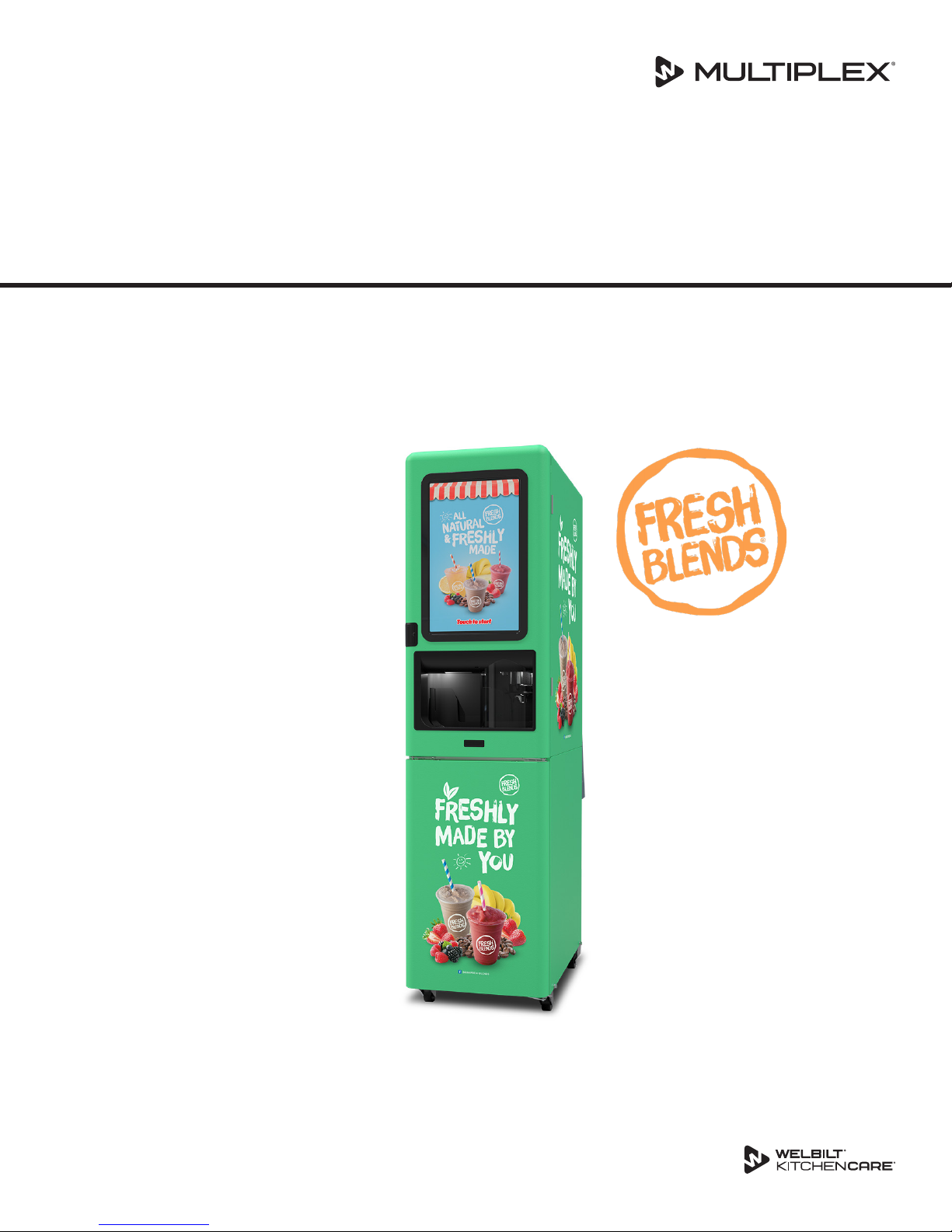
FreshBlender
Integrated Beverage Systems
Installation, Operation and Maintenance Manual
This manual is updated as new information and models are released. Visit our website for the latest manual.
Part Number: WBL-95-156 REV002
August/17/2018
Page 2
Safety Notices
As you work on Multiplex equipment, be sure to pay close
attention to the safety notices in this manual. Disregarding
the notices may lead to serious injury and/or damage to the
equipment.
Throughout this manual, you will see the following types of
safety notices:
Warning
n
Text in a Warning box alerts you to a potential personal
injury situation. Be sure to read the Warning statement
before proceeding, and work carefully.
Caution
,
Text in a Caution box alerts you to a situation in which
you could damage the equipment. Be sure to read
the Caution statement before proceeding, and work
carefully.
Procedural Notices
Read These Before Proceeding:
Caution
,
Proper installation, care and maintenance are essential
for maximum performance and trouble-free operation
of your Multiplex equipment. Read and understand
this manual. It contains valuable care and maintenance
information. If you encounter problems not covered
by this manual, do not proceed, contact Manitowoc
Foodservice. We will be happy to provide assistance.
Important
Routine adjustments and maintenance procedures
outlined in this manual are not covered by the warranty.
Warning
n
PERSONAL INJURY POTENTIAL
Do not operate equipment that has been misused,
abused, neglected, damaged, or altered/modified from
that of original manufactured specifications.
As you work on Multiplex equipment, be sure to read the
procedural notices in this manual. These notices supply
helpful information which may assist you as you work.
Throughout this manual, you will see the following types of
procedural notices:
Important
Text in an Important box provides you with information
that may help you perform a procedure more efficiently.
Disregarding this information will not cause damage or
injury, but it may slow you down as you work.
NOTE: Text set off as a Note provides you with simple, but
useful, extra information about the procedure you are
performing.
NOTE: SAVE THESE INSTRUCTIONS.
We reserve the right to make product improvements at
any time. Specifications and design are subject to change
without notice.
Page 3

Section 1
General Information
Section 2
Installation
Table of Contents
Read This Manual .............................................................................................................. 5
About the FreshBlender™ .................................................................................................. 5
Unit Inspection .................................................................................................................. 5
Model & Serial Numbers ................................................................................................... 5
How to Read a Model Number .......................................................................................5
Serial Number Location ................................................................................................... 5
Warranty Information........................................................................................................ 6
Specifications .................................................................................................................... 7
Dimensions ...................................................................................................................... 7
Capacity & Weight ........................................................................................................... 7
Product Delivery Location ...............................................................................................8
Refrigerant Charge ..........................................................................................................8
Ice Maker Production ......................................................................................................8
Electrical .......................................................................................................................... 9
Drain Connections ......................................................................................................... 10
Water Requirements ....................................................................................................... 10
Supply Connections ....................................................................................................... 10
Hard Water .................................................................................................................... 10
System Pressures ........................................................................................................... 11
Regulator Settings & Location ....................................................................................... 11
Section 3
Operation
Step-by-Step Installation ................................................................................................. 13
Pre-installation Checklist ...............................................................................................13
Connections .................................................................................................................. 14
Software ........................................................................................................................ 15
Start-up & Cleaning ....................................................................................................... 15
Demonstrate .................................................................................................................16
Post Installation Checklist .............................................................................................16
Component Identification ................................................................................................ 17
Sequence of Operation .................................................................................................... 17
Normal Operation .........................................................................................................17
Ice Making ..................................................................................................................... 18
Default Settings ............................................................................................................... 19
Cleaning ........................................................................................................................ 19
Operational Checks ......................................................................................................... 20
General .......................................................................................................................... 20
Operation ...................................................................................................................... 20
Touch Screens .................................................................................................................. 21
Main Select to Start Screen ........................................................................................... 21
Drink Selection Screen ..................................................................................................22
Flavor Selection Screen .................................................................................................23
Confirmation Screen .....................................................................................................24
Size Screen ....................................................................................................................25
Part Number: WBL-95-156 REV002 3
Page 4

Section 4
Maintenance
Section 5
Troubleshooting
Table of Contents (continued)
Employee, Managers, & Service Menu Screens ............................................................27
Product Inventory Screen .............................................................................................. 28
Assigning Flavors ........................................................................................................... 29
Product, Ice, & Water Calibration .................................................................................31
Shuttle Calibration ........................................................................................................32
Cleaning Instructions Screen ......................................................................................... 33
Other Operations ............................................................................................................ 34
Loading New Menu Recipes .......................................................................................... 34
Manual Lockout .............................................................................................................34
Usage Stats .................................................................................................................... 34
Service Inputs ................................................................................................................ 35
Service Outputs ............................................................................................................. 35
Machine ID .................................................................................................................... 35
Settings..........................................................................................................................35
Logs ............................................................................................................................... 36
Subsystem Version Info ................................................................................................. 36
General Maintenance ...................................................................................................... 37
Door Gasket Maintenance ............................................................................................37
Drain Maintenance - Inside Lower Cabinet ...................................................................37
Refrigerator ................................................................................................................... 38
Care & Cleaning ............................................................................................................. 38
Doors/Hinges ................................................................................................................38
Preventing Blower Coil Corrosion .................................................................................38
Daily Cleaning - Zone 1 .................................................................................................... 39
Approved Separate Cleaner & Sanitizers .......................................................................39
Approved Combined Cleaner & Sanitizers ....................................................................39
Gather the Following Supplies ......................................................................................39
Weekly Cleaning - Zone 2 ................................................................................................. 45
Approved Separate Cleaner & Sanitizers .......................................................................45
Approved Combined Cleaner & Sanitizers ....................................................................45
Separate Cleaner & Sanitizer Method ........................................................................... 46
Combined Cleaner & Sanitizer Method.........................................................................53
By pressing Confirm button, the weekly cleaning has been completed and the weekly timer
has been reset for 7 days ................................................................................................ 60
Monthly Tasks ................................................................................................................. 60
Ice Machine Cleaning ...................................................................................................... 61
Overview ....................................................................................................................... 61
Approved Sanitizers.......................................................................................................61
Full Ice Maker Sanitizing ................................................................................................61
Ice Machine Descaling & Sanitizing ............................................................................... 65
Removal from Service / Winterization ............................................................................. 67
General .......................................................................................................................... 67
Annual Planned Maintenance .......................................................................................... 68
Before Calling For Service Checklist ................................................................................. 69
4 Part Number: WBL-95-156 REV002
Page 5

Section 1
General Information
Read This Manual
Welbilt developed this manual as a reference guide for the
owner/operator and installer of this equipment. Please read
this manual before installation or operation of the machine.
A qualified service technician must perform installation and
start-up of this equipment. Consult Section 5 within this
manual for service assistance.
If you cannot correct the service problem, call your Service
Agent or Distributor. Always have your model and serial
number available when you call.
Your Service Agent _______________________________
Service Agent Telephone Number ____________________
Your Local Distributor______________________________
Distributor Telephone Number ______________________
Model Number __________________________________
Serial Number ___________________________________
Installation Date _________________________________
About the FreshBlender™
The FreshBlender beverage system is a self-contained
dispensing unit that allows the operator to make flavor
combinations of blended and non-blended drinks. It holds
product flavoring in a refrigerated reach-in base enclosure,
has a refrigerated ice making machine and includes one
mixing module.
The customer accesses the unit using a lighted touch
screen. Icons on the drink selection screens represent
the primary flavor combinations for the drinks. There are
multiple drink size options. Menu and software updates can
be uploaded using a USB storage device, WiFi, or Bluetooth.
On-screen instructions also include operator procedures for
cleaning/sanitizing, checking inventory, replacing product
bags, selecting drink sizes and manually preparing drinks.
Managers and technicians have access to menu/software
updates, diagnostics and other service screens.
Unit Inspection
Warning
n
Do not operate equipment that has been misused,
abused, neglected, damaged, or altered/modified from
that of original manufactured specifications.
This appliance is not intended for use by persons
(including children) with reduced physical, sensory
or mental capabilities, or lack of experience and
knowledge, unless they have been given supervision
concerning use of the appliance by a person responsible
for their safety.
Model & Serial Numbers
This manual covers the following models:
FreshBlender Beverage Systems
FB081TF
HOW TO READ A MODEL NUMBER
Platform Flavors Mixers Plug Refrigerant Hinge Optional
FB
(FreshBlender)
SERIAL NUMBER LOCATION
The FreshBlenders beverage system serial number is listed on
the serial tag affixed to the inside left and rear left of the unit.
08
(8 Flavors)
06
(8 Flavors)
1
(1 Mixer)
2
(2 Mixer)
T
(115V
60hz)
B
(220V
60hz)
Z
(Bare
Lead)
E
(Euro
16
Amp)
U
(UK 13
Amp)
F
(R-404A)
P
(R-290)
R
(Right)
L
(Left)
Used for
Build
Specific
Info
Thoroughly inspect the unit upon delivery. Immediately
report any damage that occurred during transportation
to the delivery carrier. Request a written inspection report
from a claims inspector to document any necessary claim.
See “Pre-installation Checklist” on page 13.
Warning
n
Do not damage the refrigeration circuit when installing,
maintaining or servicing the unit.
Part Number: WBL-95-156 REV002 5
Sample Serial Tag
Page 6

General Information Section 1
Warranty Information
Consult your local Service Agent or Representative for terms
and conditions of your warranty. Your warranty specifically
excludes all general adjustments, cleaning, accessories and
related servicing.
Your warranty should be activated at the time of
installation/registration or a card must be returned to
activate the warranty on this equipment. If either method
is not completed, the warranty period can begin when the
equipment leaves the Welbilt factory.
No equipment may be returned to Welbilt without a written
Return Materials Authorization (RMA). Equipment returned
without an RMA will be refused at Welbilt’s dock and
returned to the sender at the sender’s expense.
Please contact your local distributor for return procedures.
6 Part Number: WBL-95-156 REV002
Page 7
Section 1 General Information
D
E
B
C
A
F
G
H
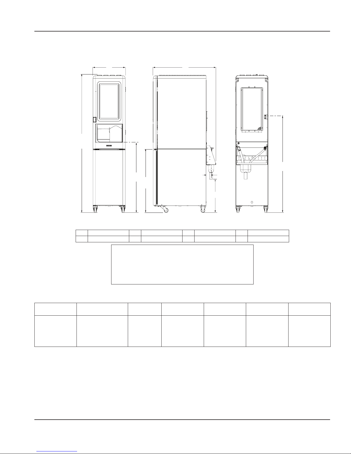
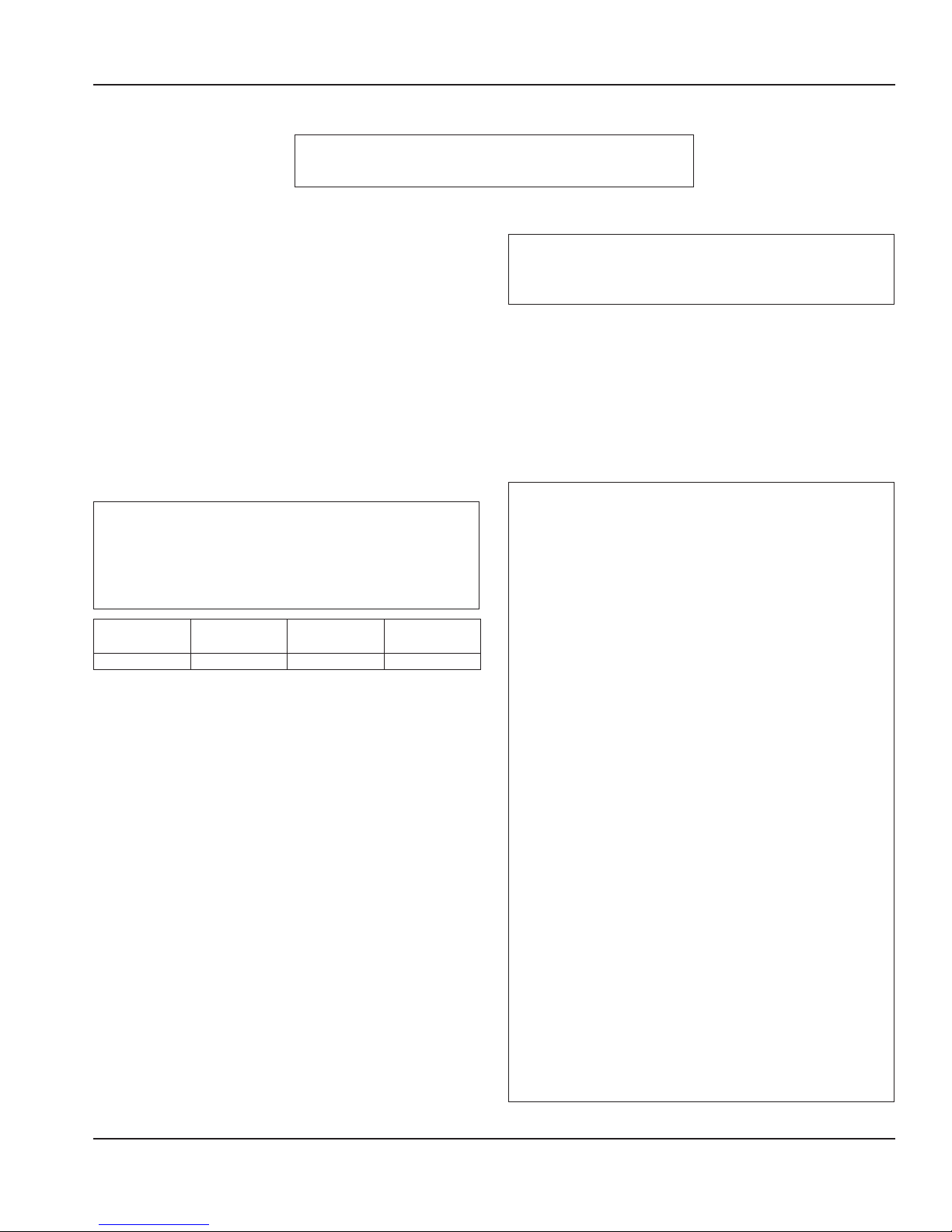
Specifications
DIMENSIONS
Front View Rear ViewSide View
A 20.26" (52 cm) C 40.13" (102 cm) E 38.79" (99 cm) G 3.08" (8 cm)
B 78.53" (200 cm) D 35.73" (91 cm) F 19.04" (48 cm) H 54.35" (138 cm)
To avoid instability the installation area must be capable
of supporting the weight of the equipment and a full
bin of ice. Additionally the equipment must be level side
to side and front to back.
CAPACITY & WEIGHT
Drink Making Ice Capacity Ice Compressor HPMax Product
1 drink in less
than 2 minutes. 30
per hour up to 2
consecutive peak
* Up to 250 lbs
(113 kg)/24 hr.
Bin Storage
30 lbs (14 kg)
1/3 19.8 lbs
hours
* Ice Capacity and Production depends on Air & Water Temperatures, See Ice Maker Production page 8
Warning
n
BinLoad
(9 kg)
Shipping
Weight
520 lbs
(236 kg)
Crated
Empty Weight Full Operating
Weight
400 lbs
(181kg)
Unpacked
No Ice/
560 lbs
(254kg)
WithIce/
Product
Product
Part Number: WBL-95-156 REV002 7
Page 8
General Information Section 1
PRODUCT DELIVERY LOCATION
The location selected for the FreshBlender Beverage System
must meet the following criteria.
• The air temperature must be at least 40°F (4°C), but
must not exceed 90°F (32°C), climate class 4.
• The location must not be near heat-generating
equipment or in direct sunlight and must be protected
from weather.
• Plain Inlet Water Temperature:
min/max = 40°F / 90°F (4°C / 32°C).
• Always use the water supply line supplied when
installing this appliance. Never reuse an old supply line.
• Verify floor of install location is level front to back, side
to side.
• Keep equipment area clear of combustible material.
Warning
n
Carbon Dioxide (CO2) displaces oxygen. Exposure to a
high concentration of CO2 gas causes tremors, which
are followed rapidly by loss of consciousness and
suffocation. If a CO2 gas leak is suspected, particularly
in a small area, immediately ventilate the area before
repairing the leak. CO2 lines and pumps must not be
installed in an enclosed space. An enclosed space can
be a cooler or small room or closet. This may include
convenience stores with glass door self serve coolers. If
you suspect CO2 may build up in an area, venting of the
B-I-B pumps and / or CO2 monitors must be utilized.
REFRIGERANT CHARGE
Important
Due to continuous improvements, this information is
for reference only. Please refer to the serial number tag
to verify electrical data. Serial tag information overrides
information listed on this page.
Model System R404A
1
FB081TF
(Lower Cabinet)
2
(Ice Maker)
ICE MAKER PRODUCTION
Acceptable incoming water temperature range is 40°F (4°C)
to 90°F (32°C). Optimum Range is 45°F (7°C) to 50°F (10°C)
(Target 50°F [10°C], results based on ARI capacity testing @
70°F [21°C] air temperature).
R-404a Ice Production
Air Temperature/
Water Temperature
70°/50°F
(21°/10°C)
90°/70°F
(32°/21°C)
Water usage/100 lbs./45.4 kgs of Ice
Potable Water: 12 gallons, 45.4 liters
24 Hour Ice
Production
261 lbs
(118 kg)
185 lbs
(84 kg)
kWh/100 lbs (45 kg)
@ 90°/70°F (32°/21°C)
8 oz
(226.8 g)
8.69
Clearances
Top 18" (46 cm)
Sides 0" (0 cm)
Back 6" (15 cm)
Front 24" (61 cm)
Warning
n
Do not obstruct machine vents or openings.
Heat of Rejection
Model System BTU
FB081TF 2300 BTU/hr (average)
8 Part Number: WBL-95-156 REV002
Page 9
Section 1 General Information
ELECTRICAL
Warning
n
All wiring must conform to local, state and national codes.
Minimum Circuit Ampacity
The minimum circuit ampacity is used to help select the
wire size of the electrical supply. (Minimum circuit ampacity
is not the FreshBlender Beverage System’s running amp
load.) The wire size (or gauge) is also dependent upon
location, materials used, length of run, etc., it must be
determined by a qualified electrician.
Voltage
A dedicated electrical circuit is required, a power cord
is provided with all units. Some models are available in
different voltages and may be equipped with a different
plug. Refer to Fresh Blends Beverage System Model/Serial
Plate for voltage/amperage specifications.
Minimum Circuit Amperage Chart
Important
Due to continuous improvements, this information is
for reference only. Please refer to the serial number tag
to verify electrical data. Serial tag information overrides
information listed on this page.
Model Voltage/Cycle/
Phase
FB081TF 120/60/1 16 20A
Total Amps Breaker Size
(Min/Max)
Grounding Instructions
Warning
n
The machine must be grounded in accordance with
national and local electrical codes.
This appliance must be grounded. In the event of
malfunction or breakdown, grounding provides a path
of least resistance for electric current to reduce the
risk of electric shock. This appliance is equipped with a
cord having an equipment-grounding conductor and
a grounding plug. The plug must be plugged into an
appropriate outlet that is properly installed and grounded
in accordance with all local codes and ordinances.
Warning
n
When using electric appliances, basic precautions must
always be followed, including the following:
A. Read all the instructions before using the
appliance.
B. To reduce the risk of injury, close supervision
is necessary when an appliance is used near
children.
C. Do not contact moving parts.
• Dedicated 20A Circuit
• NEMA5 - 20P
• Cord length 78” (198 cm)
D. Only use attachments recommended or sold by
the manufacturer.
E. Do not use outdoors.
F. For a cord-connected appliance, the following
must be included:
• Do not unplug by pulling on cord. To unplug,
grasp the plug, not the cord.
• Unplug from outlet when not in use and
before servicing or cleaning.
• Do not operate any appliance with a
damaged cord or plug, or after the appliance
malfunctions or is dropped or damaged in
any manner. Contact the nearest authorized
service facility for examination, repair, or
electrical or mechanical adjustment.
G. Follow applicable lock out tag out procedures
before working on equipment.
H. Connect to a properly grounded outlet only. See
Grounding Instructions.
Part Number: WBL-95-156 REV002 9
Page 10
General Information Section 1
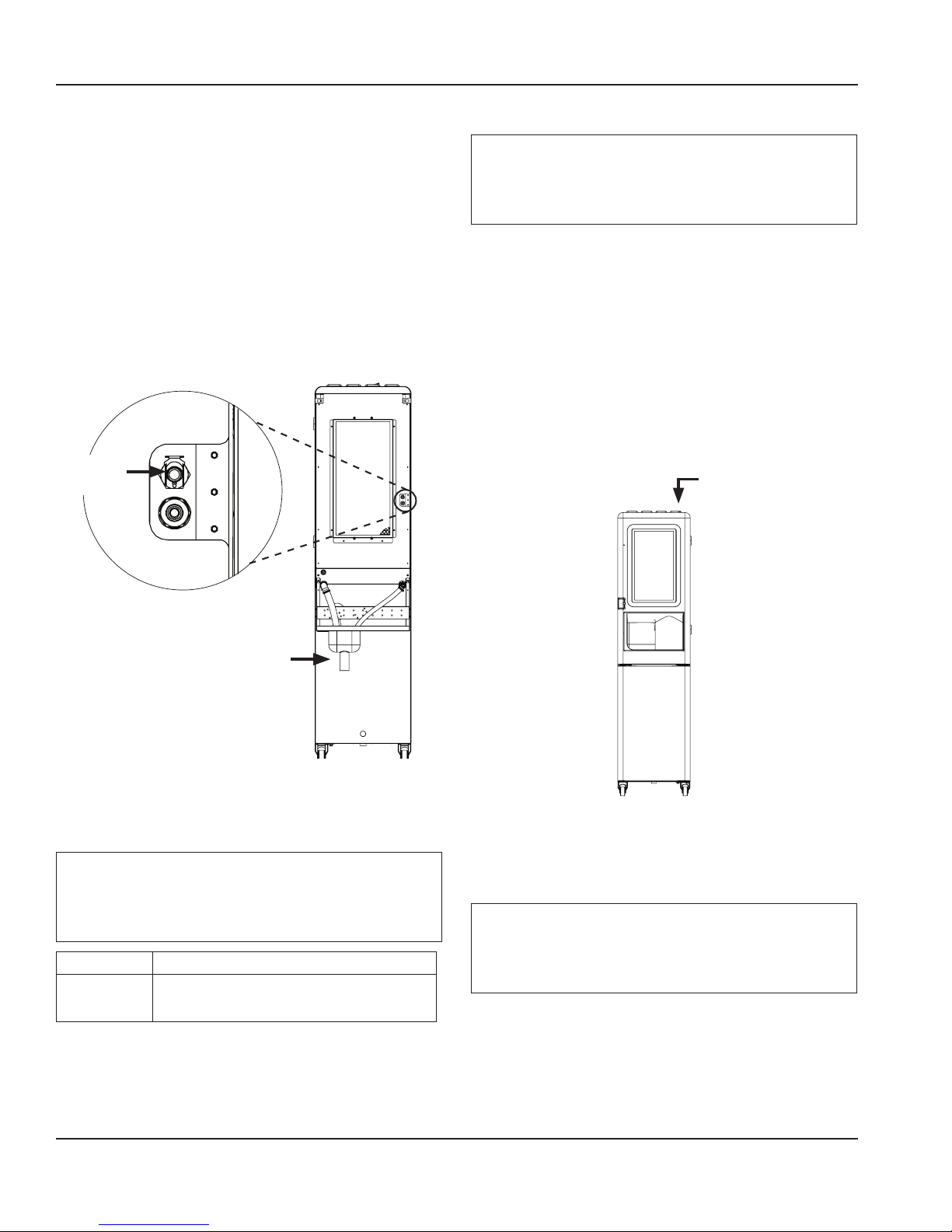
DRAIN CONNECTIONS
Models FB081TF
Drain OUT
(1½ NPS Male)
• Drain lines must have a 1.5 inch drop per 5 feet of run
(2.5 cm per meter), and must not create traps.
• The floor drain must be large enough to accommodate
drainage from all drains.
• An air gap is required for back flow prevention. Plumb
to local code.
Water Requirements
Warning
n
Connect to a potable filtered water supply only.
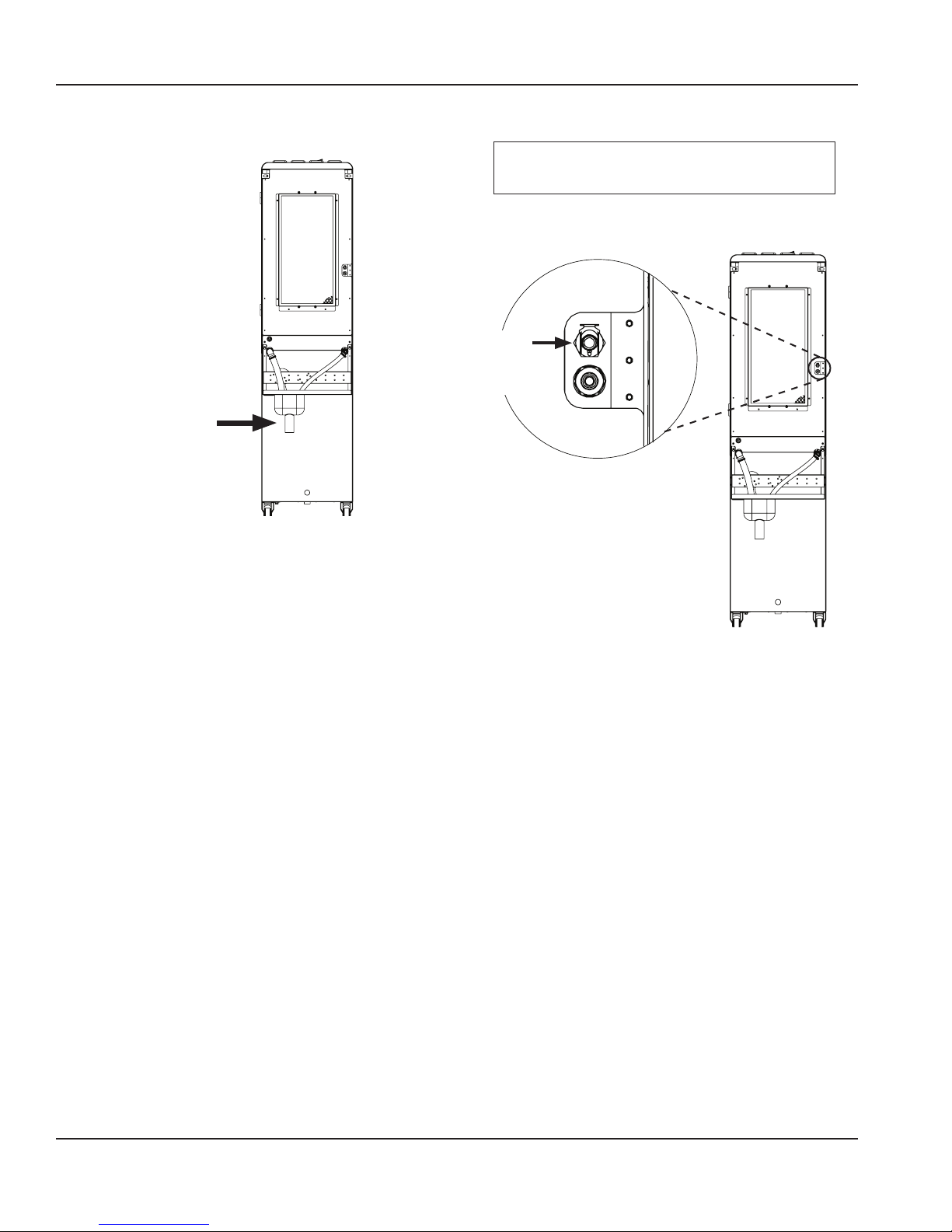
SUPPLY CONNECTIONS
Plain
Water
IN Quick
Connect
Rear of the Unit
• Use a male quick connect (supplied PN: WBL-96-087) and
6’ (1.8 m) of beverage tubing to connect labeled coupling
body fitting(s) on back of unit for the supply connection.
• Do not connect water to a hot water supply. Be sure all
hot water restrictors installed for other equipment are
working. (Check valves on sink faucets, dishwashers, etc.)
• Install a water shut-off valve in the water line at the rear
of the machine.
• Insulate water inlet lines if condensation is an issue.
• Equipment to be installed with adequate back flow
protection that meets all applicable national, state, and
local codes.
HARD WATER
All source water must be filtered. In areas where the water is
highly concentrated with minerals the water should be tested
by a water treatment specialist, and the recommendations of
the specialist regarding filtration and/or treatment should be
followed.
10 Part Number: WBL-95-156 REV002
Page 11
Section 1 General Information
SYSTEM PRESSURES
Water Supply to the Unit
Warning
n
Do not supply more than 80 psi (0.551 MPa , 551 kPa,
5.51 bar) Plain or Carbonated Water to the unit, excessive
pressure to product pumps may cause failure.
This table shows the Minimum / Maximum supply of Water
required at the rear of the machine at no flow conditions.
MINIMUM MAXIMUM
Plain Water
Supply
(0.276 MPa , 276 kPa, 2.76 bar)
40 psi
80 psi
(0.552 MPa, 552 kPa, 5.52 bar)
Important
Minimum water pressure supplied to the machine needs
to be greater than the 35 psi (0.241 MPa , 241 kPa, 2.41
bar) required during flowing conditions for pressure to
be regulated properly.
REGULATOR SETTINGS & LOCATION
Models FB081TF
NOTE: The regulator is located behind the left side panel.
Plain Water
Regulator
35 psi
(0.241 MPa , 241
kPa, 2.41 bar)
Flowing
Regulator Settings
Important
Water requires the pressure measurement to be taken
only when rinse water is spraying or dispensing (flowing
conditions).
Important
Water pressure affects the blender area cleaning, a
water booster may be required if pressure is too low.
REGULATOR SETTINGS (During Flowing Conditions)
Plain Water
(0.241 MPa , 241 kPa, 2.41 bar)
35 psi
Part Number: WBL-95-156 REV002 11
Page 12

General Information Section 1
THIS PAGE INTENTIONALLY LEFT BLANK
12 Part Number: WBL-95-156 REV002
Page 13
Section 2
Installation
Step-by-Step Installation
These instructions are provided to assist the qualified
installer. Contact your Welbilt Service Agent or call Welbilt
for information regarding start-up services.
PREINSTALLATION CHECKLIST
Keep product bags thawing in a cooler at least 24
hours prior to installation.
Important
Failure to follow these installation guidelines may affect
warranty coverage.
Any damage should be noted and reported to the
delivering carrier immediately.
Check the lower portion of the unit to be sure
casters are not bent.
Visually inspect the refrigeration package,
compressor compartment housing. Be sure lines
are secure and base is still intact.
Inspect installation location behind the unit for
electrical outlet location, water hose fittings, and
shutoff.
Check voltage at outlet dedicated for the Fresh
Blends unit.
Verify floor of install location is level front to back,
side to side and all casters are touching the floor.
Warning
n
The mass of this appliance will allow it to move
uncontrolled on an inclined surface. Adequate means
must be provided to prevent uncontrolled movement
at all times.
Remove the side panels from the unit to make the
board connections, and water regulator gauge
accessible.
Check that board connections are secure and did
not vibrate loose during shipment.
Part Number: WBL-95-156 REV002 13
Check that the micro switch is in line with the
motor above the blender.
Page 14
Installation Section 2
CONNECTIONS
See “System Pressures” on page 11 and “Regulator Settings &
Location” on page 11
Drain
See “Drain Connections” on page 10
Regulators are factory set but will need to be checked
and possibly adjusted under flowing conditions once
the unit is operational.
Important
1. Route drain line (minimum 1” ID) to drain, maintaining
a 2” (51 mm) air gap. Cut to proper length if needed (do
not leave loops in drain).
2. With the drain connected pour 1 cup of water down the
dispense/blend area drain to verify proper drainage.
Water Connection
3. Confirm correct orientation of Water fittings.
See and “Post Installation Checklist” on page 16
5. Coil excess tubing and secure with tie straps.
6. Check for any water leaks.
Electrical
See “Electrical” on page 9
7. If all electrical and grounding requirements have been
followed proceed to insert electrical plug from Fresh
Blends unit into wall receptacle.
8. Turn power switch, on the front top right of the unit, to
Plain
Water IN
the ON position.
Power
Switch
Drain OUT
(1½ NPS Male)
Rear of the Unit
4. The line set included with the unit should be equipped with
male quick connect fitting(s) for the water supply line(s).
Important
Leave enough slack in the water and drain lines to allow
access to the rear of the machine without disconnecting
the lines.
REGULATOR SETTINGS (During Flowing Conditions)
Plain Water
(0.241 MPa , 241 kPa, 2.41 bar)
35 psi
Front of Unit
9. The touch screen should energize and inform the user to
perform Zone 2 Weekly cleaning before the unit can be
put into operation. See “Start-up & Cleaning” on page 15
Important
Product or caps need to be in place before cleaning
and sanitizing the machine or water will flood the
refrigeration cabinet..
NOTE: With both the water and power on the unit will begin
to make ice 15 minutes after start up.
14 Part Number: WBL-95-156 REV002
Page 15
Section 2 Installation
SOFTWARE
10. Verify correct UI version, firmware, drink menu, and
flavors are available.
PLeaSe SelEct a
caTegOry of
yoUr ChoIce!
Drink Selection Screen
(Drink choices will vary depending on loaded recipe file)
STARTUP & CLEANING
Important
During first time start up be sure to perform the Weekly
Cleaning before loading any product through the UI,
product bags will need to be in place to perform cleaning.
Checklist
Review before proceeding to Start-Up & Cleaning.
Has all of the internal packing been removed?
Have all of the electrical and water connections
been made?
Clean & Sanitize
11. Perform Weekly Cleaning on the Fresh Blends machine
by entering the one of the following screens, Employee,
Manager, or Service Menu.
See “Weekly Cleaning - Zone 2” on page 45
NOTE: The these screens are hidden and will require a
password. From a start screen, touch the three corners in the
order shown below to access the password screen. Leave the
field blank and Press Enter to access the Employee Menu.
Manager and Service Menus require passwords.
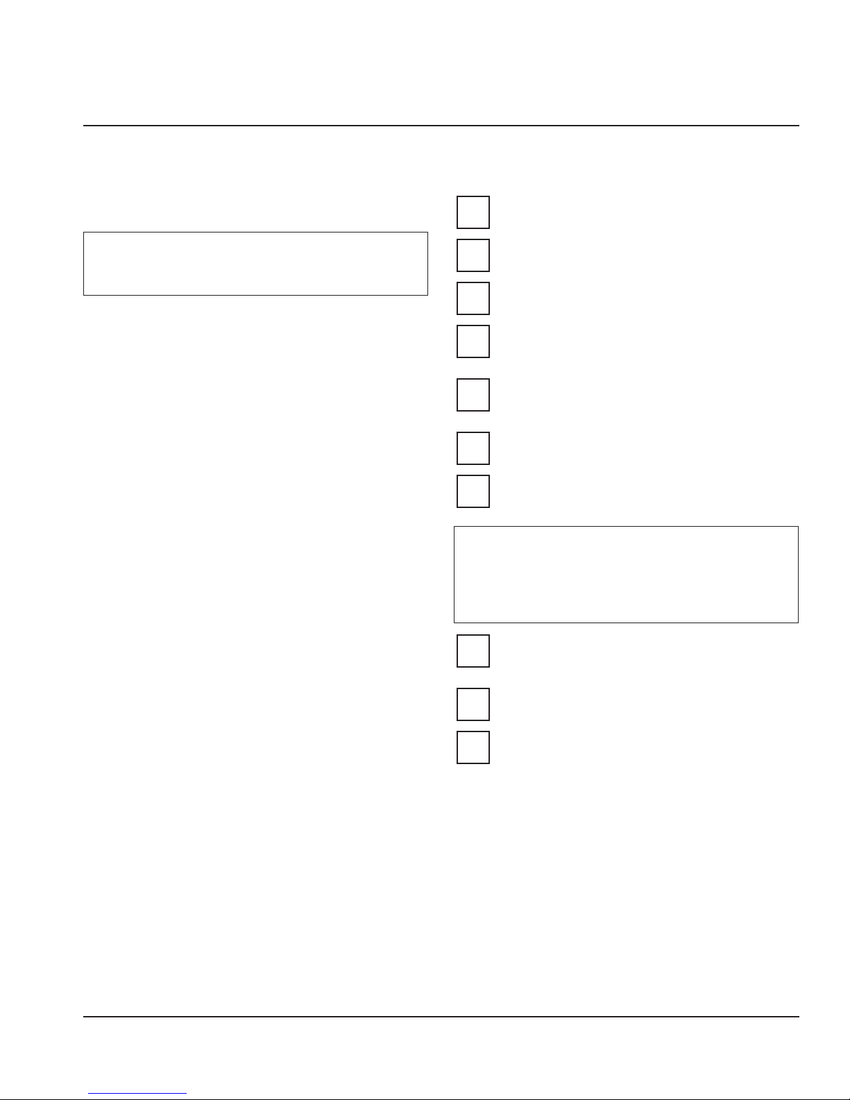
3
4
1 2
NOTE: If the TOUCH TO START or OUT OF SERVICE screen
is not currently displaying on the machine you must first
enter a Flavor Selection screen then double tap the BACK
button to bring the TOUCH TO START screen back up.
12. Select the Cleaning Instructions button, then Weekly
(Zone 2). Clean and sanitize the Fresh Blends machine
by following the on screen instructions.
Is there proper clearance around the machine for
air circulation?
Is the machine grounded / polarity correct?
Has the machine been installed where the
incoming water temperature will remain in the
range of 40°F / 90°F (4°C / 32°C)?
Has the regulator been properly set? This can be
done/checked during cleaning.
Has the blender splash shield sensor and shuttle
positions been checked?
NOTE: See “Weekly Cleaning - Zone 2” on page 45 for step
by step Weekly Cleaning instructions including supplies and
solutions need.
Has the Power switch on the top of the unit been
turned to the ON position?
Is the correct UI, Firmware, and Menu loaded on
the unit?
Are 8 products or sanitation caps in place in
the lower refrigeration cabinet prior to Zone 2
cleaning?
Part Number: WBL-95-156 REV002 15
Page 16

Installation Section 2
The following will have been completed once the unit is cleaned;
A. All beverage lines, dispense area, and blender
chambers, cleaned and sanitized.
B. Water run through the drain to verify it is draining
properly.
C. Verify all regulators are set correctly during
cleaning.
NOTE: During the cleaning process is an ideal time to verify
pressure regulator settings during flowing conditions. See
“Regulator Settings & Location” on page 11
D. Product bags retrieved from walk-in cooler,
installed into the product bins and placed into
their proper location in the cabinet.
E. All product lines primed and ready for use.
Load Product & Label
13. Add labels to product bins if used, be sure to put labels
in the correct place.
14. Add labels anywhere else on the unit required.
15. Enter the Managers or Service Screen and enter the
Inventory screen to load each product into their
assigned bin.
CALIBRATE
16. Once enough ice has built up in the bin, 30 - 60 min,
ice calibration can be performed, calibrate both ice and
water through the Service>Calibration screen.
NOTE: Product calibration is not required at this time unless
over or under filling is seen when testing drinks.
DEMONSTRATE
21. Demonstrate using the Interface. See “Touch Screens”
on page 21.
22. Demonstrate how to make drink. See “Procedure to
Make a Drink” on page 26.
23. Demonstrate Manager Menu options, using the
default password. (The password can be changed.)
See “Employee, Managers, & Service Menu Screens” on
page 27.
24. Set date and time to activate warranty.
25. Complete start-up form, sign, and have store manager
sign form. (Fax to number on form.)
POST INSTALLATION CHECKLIST
Has the machine been properly sanitized?
Has each flavor been installed and primed?
Has the plain water regulators been correctly set
during flowing conditions?
Is the machine cycling ON/OFF on the temperature
control?
Has the owner/operator been instructed regarding
maintenance procedures?
Has the owner/operator completed the warranty
registration card?
26. Once completed, the FreshBlender machine is ready for use.
17. Reinstall any removed panels.
18. Push the FreshBlender unit into place
19. Verify the unit is level and shim if necessary.
20. Run test drinks through the drink making menu to
verify fill levels are accurate, calibrate any flavors that
require adjustment.
NOTE: If product calibration is required do so once
operating temperature has been reached. See “Product,
Ice, & Water Calibration” on page 31 for step-by-step
calibration instructions.
16 Part Number: WBL-95-156 REV002
Page 17
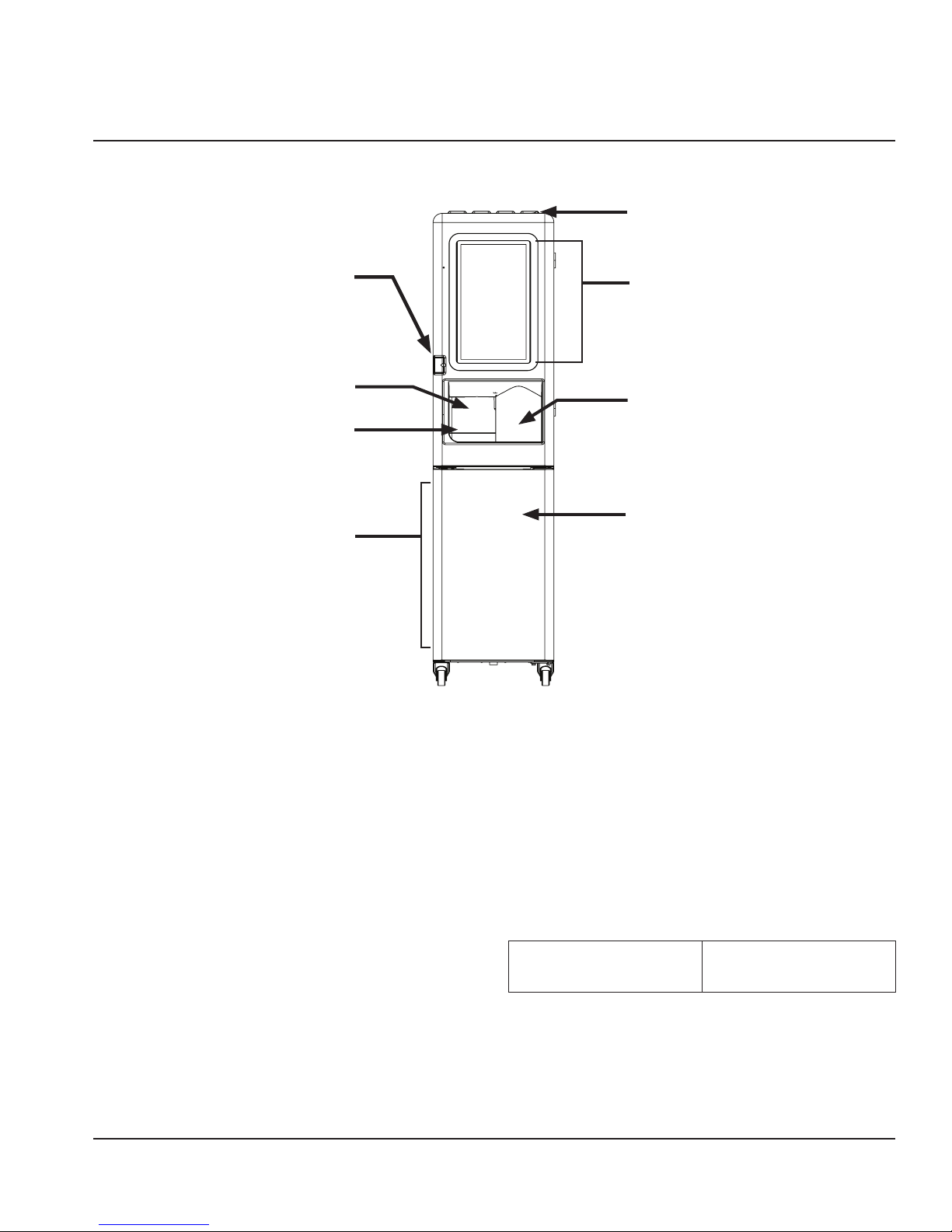
Component Identification
Section 3
Operation
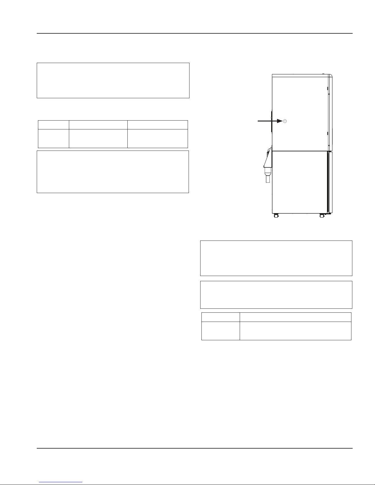
Power Switch
(Inside Cabinet)
Sequence of Operation
Front Panel
Keyed Lock
Product
Dispense Area
Drink Shuttle
& Rail
Product Bins
Touch Screen
Clear Splash
Shield &
Blending
Area
Refrigerated
Cabinet Door
NORMAL OPERATION
Drink Selection screen appears after power-up of the
unit. Operator presses one of the drink type buttons on
the Drink Selection screen, and the Flavor Options screen
appears. Once a flavor is selected a confirmation screen will
appear. When the user confirms the selection the on screen
instructions for cup location and drink size will then display.
See “Procedure to Make a Drink” on page 26.
With correct cup in place, the drink preparation sequence
commences when “Start Drink Size” is initiated through
the touch screen. The machine dispenses product and ice
into the cup in the dispense area. The cup is then placed
into isolated the blend chamber by the automatic shuttle
The machine blends the drink for the correct time at the
proper blender speed. If add-ins are required for the drink
after blending, the user will be prompted. The blender
completes the blend sequence and the shuttle system
moves the completed drink back into the dispense area
where the customer can now retrieve it.
After the drink is removed the automatic rinse of the
blender and dispense area initiates. The Drink Selection
screen re-appears.
Default Temperature
ControlSetting
34°F/1°C set point
4°F/.5°C differential
controlled by software
system.
Part Number: WBL-95-156 REV002 17
Page 18
Operation Section 3
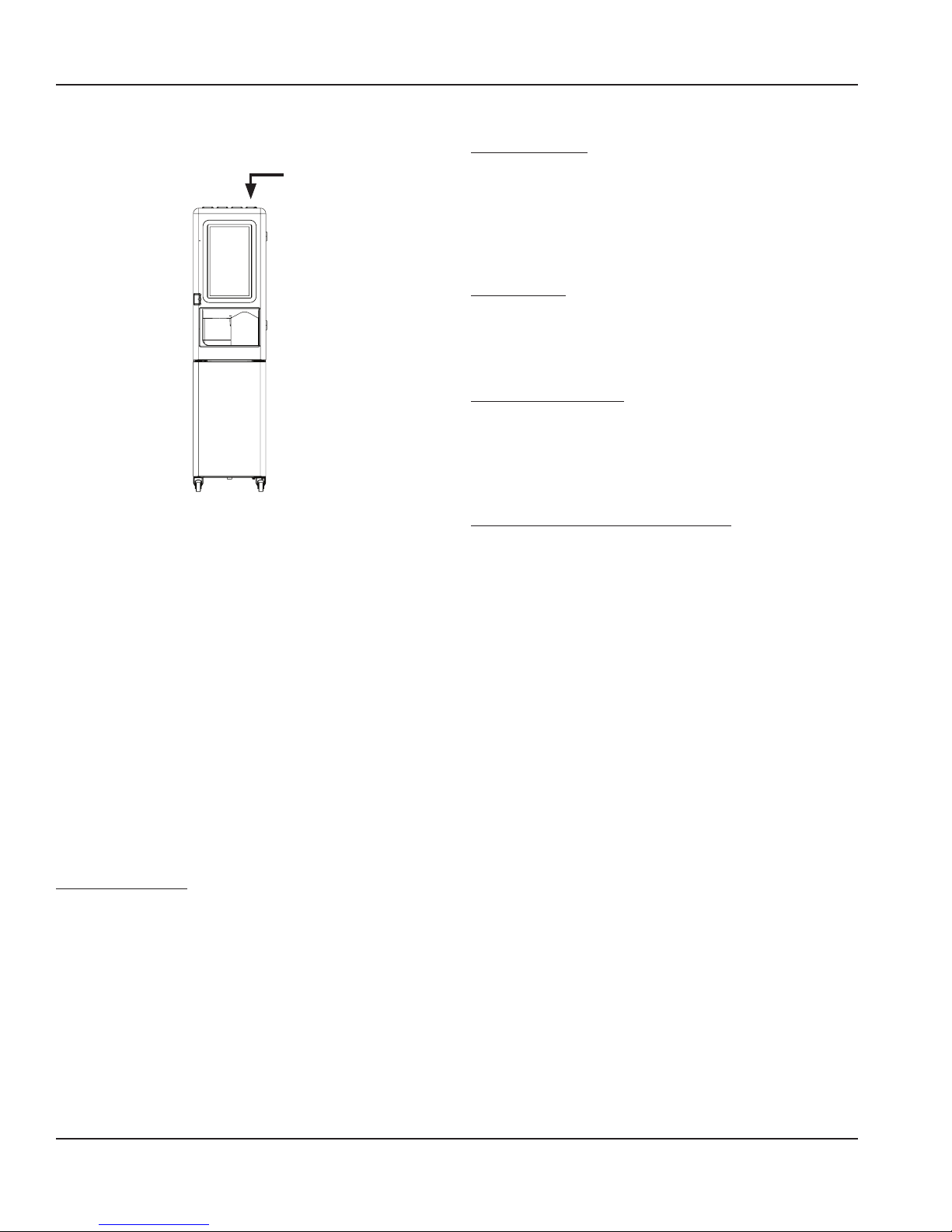
ICE MAKING
Main Power Switch - Front Top Right of the Unit
Power
Switch
The ice machine will not start until:
1. The power ON/OFF switch is in the “ON” position.
2. Ice does not contact the bin level sensor/switch.
3. The water reservoir is full of water.
4. After 15 minute delay when power cycled.
15 Minute time delay
The 15 minute delay must be expired before the gear motor
or compressor will energize.
The delay period starts to time out upon application of
power or movement of the toggle switch from OFF to ICE.
The delay period starts when:
• The ice machine enters Automatic Shutoff
• Power is disconnected and reconnected
• The toggle switch is moved from OFF to ICE
This time delay period can not be overridden and will reset
to 15 minutes if any of the above conditions occur.
INITIAL STARTUP
Applying power and/or moving the toggle switch from OFF
to ICE will start a 15 minute delay period. This delay period
can not be overridden. With the water sensing switch closed
(reservoir full of water) the gear motor will energize at the end
of the 15 minute time delay. The compressor and condenser
fan motor energize 5 seconds after the gear motor.
FREEZE CYCLE
The float valve automatically maintains the water level in
the reservoir. The ice damper will open and close to verify
ice production. The ice machine will continue to make ice
until the ice damper is held open (up) as ice fills the bin.
AUTOMATIC SHUTOFF
When the ice damper is held open by ice, the gear motor,
compressor and condenser fan de-energize. The fifteen
minute delay period starts to time out. The ice machine will
remain off until the 15 minute delay period expires and the
ice damper closes.
RESTART AFTER AUTOMATIC SHUTOFF
1. Less than 4 hours have passed since automatic shut-off.
With the water sensing switch closed (reservoir full of water)
the gear motor will energize at the end of the 15 minute time
delay. The compressor and condenser fan motor energize 5
seconds after the gear motor.
2. More than 4 hours have passed since automatic shut-off.
The dump valve energizes to drain the evaporator. After 30
seconds the dump valve de-energizes. When the reservoir
fills with water, the water sensing switch closes and the gear
motor energizes. The compressor and condenser fan motor
energize 5 seconds after the gear motor.
NOTE: Ice machines use an auger to remove ice from the
evaporator. Occasional noises (creaks, groans, squeaks, or
pops) are a normal part of the ice making process.
PRIOR TO STARTUP
When the toggle switch is placed in the ICE position the following
must occur in the listed order before ice making will start.
• The ice chute damper must be in the closed or down
position.
• The 15 minute delay period must be expired. The delay
period starts upon application of power or toggle switch
movement from OFF to ICE.
• The water sensing switch must be closed (water reservoir
full of water and water sensing float in the up position).
18 Part Number: WBL-95-156 REV002
Page 19
Section 3 Operation
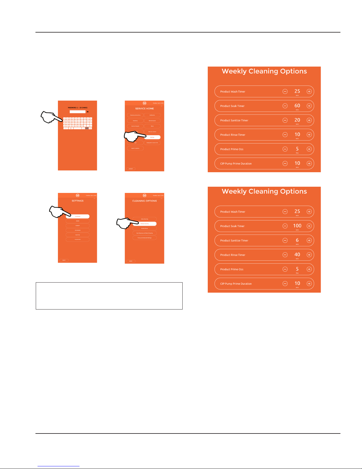
Default Settings
CLEANING
For the unit to clean properly the following needs to be the
minimum cleaning settings.
This can be checked through the Managers or Service
Screen options.
• Enter the Managers or Service menu and touch the
Settings button.
Separate Cleaner/Sanitizer Settings
Combined Cleaner/Sanitizer Settings
• Choose Cleaning>Weekly Cleaning to verify or change
these settings.
Important
Settings should never be set below Minimum settings
listed below.
Part Number: WBL-95-156 REV002 19
Page 20
Operation Section 3
Operational Checks
GENERAL
Ice machines are factory-operated and adjusted before
shipment. Normally, a newly installed ice machine does not
require any adjustment.
To ensure proper operation, always follow the Operational
Checks:
• When starting the ice machine for the first time
• After a prolonged out of service period
• After cleaning and sanitizing
NOTE: Routine adjustments and maintenance procedures
outlined in this manual are not covered by the warranty.
Power Switch
The power switch must be placed in the ON position to
make ice.
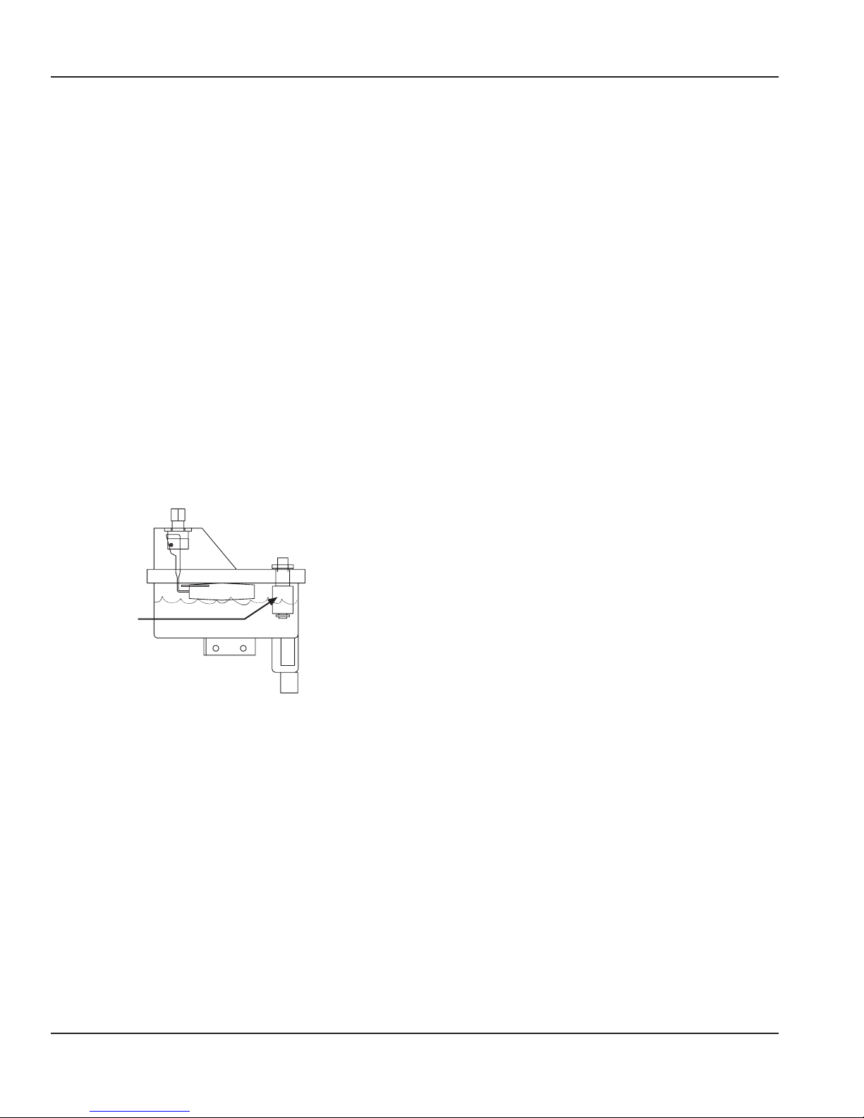
Water Reservoir
The water reservoir must be 2/3 full of water and the water
sensing float must be up (switch closed) before the ice
machine will start.
WATER
SENSING
FL OAT
Ice Production
Allow the ice machine to produce ice for 15 minutes before
testing the dispense mechanism. This will insure a sufficient
quantity of ice in the bin for dispensing.
OPERATION
1. Make a drink.
Select a drink from the drink menu and make a drink.
2. Calibrate Ice
Perform Ice Calibration by accessing Calibration in the
Manager or Service menu. See “Product, Ice, & Water
Calibration” on page 31.
20 Part Number: WBL-95-156 REV002
Page 21
Section 3 Operation
Touch Screens
The main user screen is for the drink making procedure: Drink Selection displays by default at start-up. The Service and
Manager’s Menu for accessing the machine’s settings is hidden and password protected. Inventory, Cleaning, and other
Service oriented screens are also available through the password protected area.
MAIN SELECT TO START SCREEN
The Drink Selection screen appears on power-up (except where clean/sanitize limitations have been exceeded, in which
case the Cleaning screen appears). See “Component Identification” on page 17 for Daily, Weekly and Monthly cleaning/
sanitation. The Drink Selection screen’s primary function is to select a drink to make or to access the Main Menu.
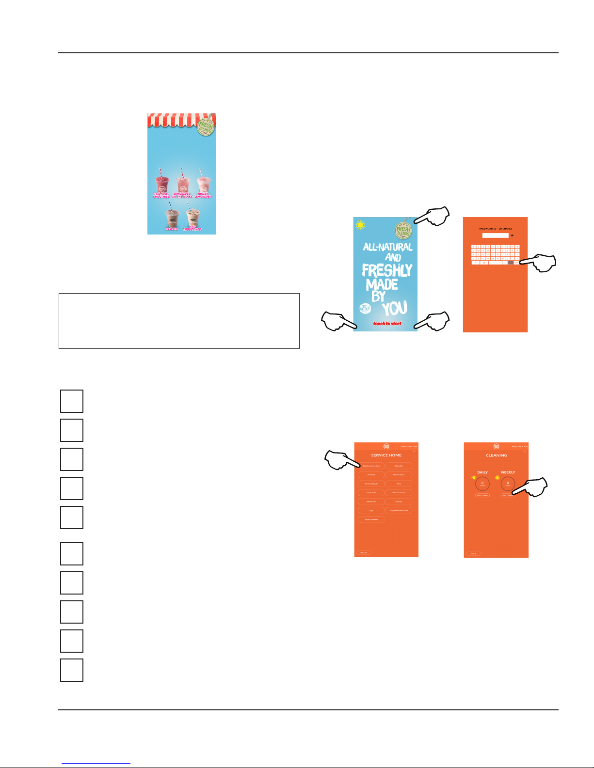
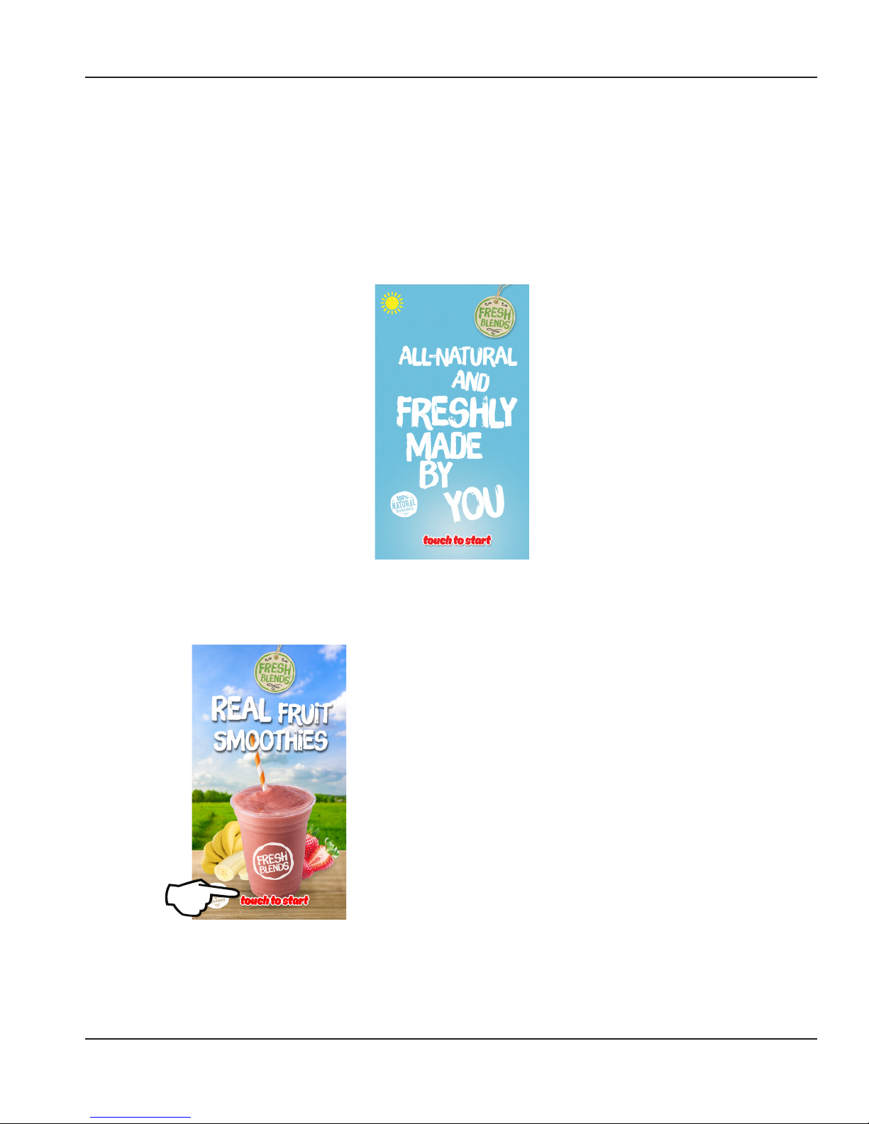
How to Access
The Touch to Start screens display by default unless
cleaning is required or drink selection is being made.
NOTE: Touch the Touch to Start icon to proceed to drink
choices
Icon Button Descriptions
• Touch to Start
Touching this icon begins the drink selection process.
NOTE: Available drink selections may vary depending on
the recipe file installed.
• Password Screen
To access the hidden password screen touch the bottom
left, right then top right corners of the screen in that
order. Once the password screen appears press enter to
go to the Employee screen or enter the password for the
Manager’s or Service menu.
• Cleaning Reminders
When due, an icon displays the time remaining in days
until ZONE 2 (Weekly) and ZONE 3* (Monthly) cleaning
is required.
* If equipped with this feature.
Part Number: WBL-95-156 REV002 21
Page 22
Operation Section 3
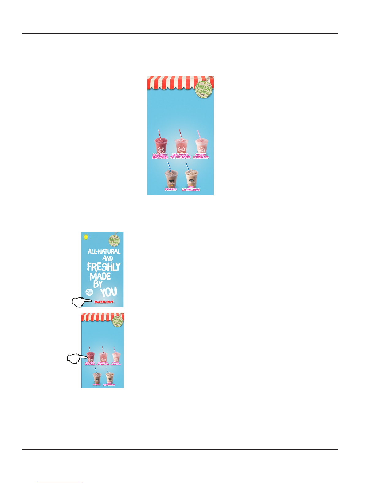
DRINK SELECTION SCREEN
The category screen is the start of the drink making procedure. The Drink Selection screen appears after the Touch to Start icon has
been touched. The Drink Selection screen’s primary function is to select a drink category and start the drink making process.
PLeaSe SelEct a
caTegOry of
yoUr ChoIce!
How to Access
The Drink Selection screen displays after touching the
Touch to Start icon in the main screen.
PLeaSe SelEct a
caTegOry of
yoUr ChoIce!
Icon Button Descriptions
• Drink Categories
The main product categories are displayed left to right
on the Drink Selection screen. Touching a category will
display the drink flavor options available for the category.
NOTE: Available drink selections may vary depending on
the recipe file installed.
• Cleaning Reminders
When due, an icon displays the time remaining in days
until ZONE 2 (Weekly) and ZONE 3* (Monthly) cleaning
is required.
* If equipped with this feature.
Select a Category to continue to next screen.
22 Part Number: WBL-95-156 REV002
Page 23
Section 3 Operation
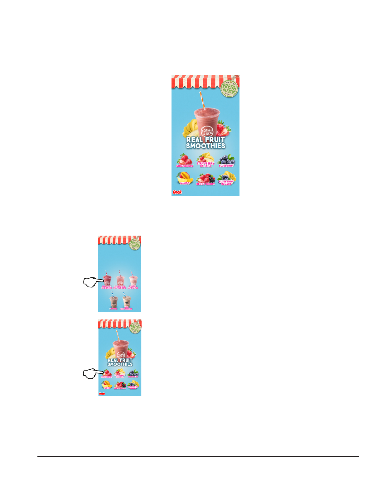
FLAVOR SELECTION SCREEN
The Flavor Selection screen appears after a Drink Selection has been made. Flavor options will vary depending on what
recipes are configured on the unit. This screen’s primary function is to select a drink flavor.
$2.99 $2.99 $2.99
$2.99 $2.99 $2.99
Please select a flavor of your choice!
How to Access
The Flavor Selection screen displays after a drink selection
has been made from the Drink Selection screen.
PLeaSe SelEct a
caTegOry of
yoUr ChoIce!
$2.99 $2.99 $2.99
$2.99 $2.99 $2.99
Please select a flavor of your choice!
Icon Button Descriptions
• Drink Flavor Buttons
Flavor choices for the drink type that was selected.
NOTE: Available flavor selections may vary depending
on the recipe file installed.
• Back Button
Navigates back one screen.
• Cleaning Reminders
When due, an icon displays the time remaining in days
until ZONE 2 (Weekly) and ZONE 3* (Monthly) cleaning
is required.
* If equipped with this feature.
Select Flavor to continue to next screen.
Part Number: WBL-95-156 REV002 23
Page 24

Operation Section 3
You’ve selected a
Please click here to confirm your selection
STraWbeRry
smOotHie
You’ve selected a
CONFIRMATION SCREEN
The Confirmation screen appears after a drink flavor has been chosen from the Flavor Selection screen. This screen’s primary
function is to verify the customer’s drink choice. Optional Add-Ins are also performed through this screen if the drink
requires them.
How to Access
The Flavor Selection screen displays after a drink selection
has been made from the Drink Selection screen.
PLeaSe SelEct a
caTegOry of
yoUr ChoIce!
$2.99 $2.99 $2.99
$2.99 $2.99 $2.99
Please select a flavor of your choice!
STraWbeRry
smOotHie
The screen will display all selected drink information and
prompt customer to confirm.
• Back Button
Navigates back one screen.
• Cleaning Reminders
Displays the time remaining in days until ZONE 2
(Weekly) and ZONE 3* (Monthly) cleaning is required.
* If equipped with this feature.
Please click here to confirm your selection
Select “Confirm Selection“ to continue to next screen
24 Part Number: WBL-95-156 REV002
Page 25

Section 3 Operation
SIZE SCREEN
The Size screen appears after a drink flavor has been confirmed from the Confirmation screen. This screen’s primary function
is to select size and make a drink.
Icon Button Descriptions
• Drink Size Buttons
Press a drink size (SMALL, MEDIUM, or LARGE) to start
the drink making process.
• Back Button
Navigates back one screen.
NOTE: Make sure the correct cup is in place before
pressing the drink size button, once one is selected the
unit will start dispensing ice and product, the screen will
display “DISPENSING“. Other entertainment, animation,
games or advertisements may also display on this screen
during this time.
Dispensing & Blending Screens
IT’s fiNisHed!
DIspEnsIng…
14%
PLeaSe Wait
ANd Don’t TakE
yOur cuP yEt
BLenDing…
14%
PLeaSe Wait
ANd Don’t TakE
yOur cuP yEt
PLeaSe TakE yOur
drInk anD hAve
a niCe Day!
• The dispensing screen displays as ice and product
dispense into the cup. An on screen percentage will
display the amount until dispense is finished.
NOTE: Once dispense is complete the cup will automatically
move into the blend chamber.
• Once the drink has automatically moved into the
blend chamber, the blend screen will then display. An
on screen percentage will display the amount until
blending is finished.
NOTE: The screen will display “Blending“. Other
entertainment, animation, games or advertisements may
also display on this screen during this time.
Part Number: WBL-95-156 REV002 25
• When the blending process is complete the screen will
prompt the customer it is finished and the drink will
automatically move back into the dispense area.
Page 26

Operation Section 3
You’ve selected a
Procedure to Make a Drink
NOTE: Ice must be present in the ice hopper, product must be connected and primed to produce a drink.
1. The Drink Selection screen displays after touching
Touch to Start.
PLeaSe SelEct a
caTegOry of
yoUr ChoIce!
NOTE: Drink choices will vary depending on loaded recipe file
2. The Flavor Selection screen displays after a drink selection
has been made from the Drink Selection screen.
5. The Size screen appears after a drink flavor has been
confirmed from the Confirmation screen.
NOTE: Make sure the correct cup is in place before
pressing the drink size button.
6. Select the size to start dispensing ice and product, the
screen will display “DISPENSING“.
DIspEnsIng…
14%
$2.99 $2.99 $2.99
$2.99 $2.99 $2.99
Please select a flavor of your choice!
3. Select Flavor to continue to next screen
STraWbeRry
smOotHie
Please click here to confirm your selection
4. Select “Confirm Selection“ to continue to next screen
PLeaSe Wait
ANd Don’t TakE
yOur cuP yEt
7. Once the drink has automatically moved into the blend
chamber, the blend screen will then display. An on
screen timer will count down the time remaining until
blending is finished.
IT’s fiNisHed!
BLenDing…
14%
PLeaSe Wait
ANd Don’t TakE
yOur cuP yEt
8. The screen will display “Blending“. Other entertainment,
animation, games or advertisements may also display
on this screen during this time.
9. When the blending process is complete the screen
will prompt the customer it is done and the drink will
automatically move back into the dispense area.
PLeaSe TakE yOur
drInk anD hAve
a niCe Day!
26 Part Number: WBL-95-156 REV002
Page 27

Section 3 Operation
EMPLOYEE, MANAGERS, & SERVICE MENU SCREENS
Accessed though the main start screen, this screen’s primary function is to provide access to cleaning, bag change procedures and
other functions specific to the user accessing them. Only certain functions can be performed on the unit by an employee, manager
or service technician. It takes a special touch sequence to access these screens and is password protected.
3
1 2
Employee Menu Screen Items
• Leave the password field blank and touch the ENTER
button to enter the Employee menu.
• For managers, type the Managers password then touch
ENTER.
• For service technicians, type the Service password then
touch ENTER.
Part Number: WBL-95-156 REV002 27
Page 28

Operation Section 3
PRODUCT INVENTORY SCREEN
This screen’s primary function is to provide visual product inventory information for the user. The Product Inventory screen is
normally accessed through the Main Menu.
The inventory screen visually displays levels for all flavors. Underneath each flavor is the time remaining until the flavor
expires in days. NOZZLE and CABINET temperatures are also on the inventory screen. When a flavor is touched on the screen,
the instructions to replace a product bag will begin. (See “Procedure to Install a Product Bag” on page 30)
How to Access
This is done through the Employee, Managers, or Service
Screen options.
• Enter the Employee, Managers, or Service menu.
28 Part Number: WBL-95-156 REV002
Page 29

Section 3 Operation
ASSIGNING FLAVORS
Accessed though the main start screen, this screen’s primary function is to provide access to all other procedures and adjustments
that can be performed by a manager on the unit. It takes a special touch sequence to access and is password protected.
Enter Password
1. This is done through the Employee, Managers, or
Service Screen options.
• Enter the Employee, Managers, or Service menu.
2. Choose a slot and then choose a flavor/product type
that is loaded into the bin.
3. Follow the on-screen instructions and prime the product.
NOTE: In order to dispense product a product bag must be loaded
(See “Procedure to Install a Product Bag” on page 30) and
calibrated (See “Product, Ice, & Water Calibration” on page 31).
Part Number: WBL-95-156 REV002 29
Page 30

Operation Section 3
Procedure to Install a Product Bag
This is done through the Employee, Managers, or Service
Screen options.
1. Enter the Employee, Managers, or Service menu. See
“Employee, Managers, & Service Menu Screens” on
page 27
7. Slide the loaded product bin into it’s slot in the lower
refrigeration cabinet and latch into place.
NOTE: Do not force the latch over the pump, if the latch
does not snap into place adjust the pump until it properly
seats on the sanitation fitting and latches easily.
8. Close the refrigeration door and place a cup into the
dispense area.
9. Press the prime button to prime the bag.
2. Select the INVENTORY button.
3. Choose the corresponding slot on the screen where
the bag was just loaded. If the slot was empty the circle
icon representing the slot will read LOAD BAG. If there is
already product in the slot it will display the flavor name.
• If loading a new bag in an empty slot the screen
will display EMPTY. Press the LOAD BAG button.
• If reloading an existing flavor the screen
will display the flavor and options for BAG
REMOVAL, BAG RELOAD, or PRIME. Choose to
RELOAD if loading the same flavor, or REMOVAL
if loading a different flavor.
NOTE: When loading a new bag you will need to assign a
flavor following the instructions on the screen and scrolling
to the flavor being loaded.
NOTE: When performing a BAG REMOVAL the screen will
instruct you on removal and you will then be taken back to
the setup screen to load a new bag.
4. After assigning a flavor or pressing BAG RELOAD the
screen will instruct on how to load the bag in the lower
refrigeration cabinet.
5. Remove product bin from the cabinet, discard existing
product bag if there is one.
6. Wipe down and clean the product bin before installing
the new product bag into the bin.
NOTE: When installing the new product bag make sure the
product pump is facing he correct way with the product
elbow pointing towards the back of the bin and properly
snaps into the bin.
30 Part Number: WBL-95-156 REV002
Page 31

Section 3 Operation
PRODUCT, ICE, & WATER CALIBRATION
Important
Allow cabinet to reach operating temperature 34°F –
Gather the following supplies
Digital Scale Set to ounces
38°F (1°C – 3°C) before calibrating. Calibration will be
inaccurate if performed above operating temperatures.
Empty & Clean Cups
Pre-calibration Checklist
If calibrating ice verify bin is at least half full.
1. Enter the Employee, Managers, or Service Screen options.
If calibrating ice, go to Service> Outputs> Ice
Motor Menu and manually dispense 2 large cups of
ice prior to calibrating.
Check for empty product bags in the cabinet and
replace if necessary.
Ensure that each flavor has a bag more than 1/3 full.
Check bag to ensure the spout is securely locked in
position and the spout side of bag is facing down.
Ensure product flavors to be calibrated have been
refrigerated for 24 hours in a 34°F/1°C – 40°F/4°C
environment and the product cabinet is at
operating temperature 32°F/0°C – 34°F/1°C.
Check Zone 2 cleaning was completed over 1 hour ago.
Check that Machine has been turned on for at least
1 hour – Do not proceed with this check during
peak time - Dispense 2 large cups of ice.
2. Select the CALIBRATION button.
3. Select what is going to be calibrated, ICE, WATER or
FLAVOR.
NOTE: If calibrating ice or water these will only dispense 1
time, flavors will take an average of 3 -5 dispenses.
4. Follow the on screen instructions and place a cup in the
dispense area.
5. Press the button to dispense when ready.
6. When dispense has finished weigh the cup and enter
the weight of the dispense into the screen, then press
enter.
7. Repeat this 3 - 5 times as prompted by the screen.
8. Once completed you will be returned to the main
calibration screen.
9. The ice, water, or flavor is now calibrated, go back to
calibrate more flavors or press back and logout to go
back to the drink making screen.
Part Number: WBL-95-156 REV002 31
Page 32

Operation Section 3
SHUTTLE CALIBRATION
This is done through the Employee, Managers, or Service
Screen options.
• Enter the Employee, Managers, or Service menu.
1. Select the CALIBRATION button.
2. Select Shuttle Calibration.
32 Part Number: WBL-95-156 REV002
Page 33

Section 3 Operation
CLEANING INSTRUCTIONS SCREEN
The Cleaning screen appears after selected from the Main Menu or when prompted to perform routine cleaning. This
screen’s primary function is to perform routine cleaning and sanitation of the machine.
How to Access
This is done through the Employee, Managers, or Service
Screen options.
• Enter the Employee, Managers, or Service menu.
Important
Once the time limit has been exceeded the machine
will no longer make a drink until cleaning has been
completed.
See “Maintenance” on page 37 for all daily and weekly
cleaning instructions.
Part Number: WBL-95-156 REV002 33
Page 34

Operation Section 3
Other Operations
LOADING NEW MENU RECIPES
How to Access
This is done through the Managers or Service Screen
options only.
1. Enter the Managers or Service menu.
2. Select the SYSTEM UPDATES button and choose MENU.
3. Press CHECK FOR UPDATE if the button appears.
4. If a new menu is available or has been sent to the
machine it will display here as available for download.
5. Press UPDATE to begin the download and let the unit
proceed to download then apply the update.
6. The screen should then reboot on its own to complete
the update.
Once the screen comes back up and the drink making
screen appears the new menu will be available. Reloading
or loading of new product may be necessary.
MANUAL LOCKOUT
How to Access
This is done through the Managers or Service Screen
options only.
1. Enter the Managers or Service menu.
2. Select the MANUAL LOCKOUT button.
3. Through this screens toggle you can lock the unit,
preventing users from making drinks.
NOTE: This screen may be helpful if it needs to be down for
maintenance or other reasons.
USAGE STATS
How to Access
This is done through the Managers or Service Screen
options only.
34 Part Number: WBL-95-156 REV002
1. Enter the Managers or Service menu.
2. Select the USAGE STATS button.
3. This screen displays usage stats for the unit.
Page 35

Section 3 Operation
SERVICE INPUTS
How to Access
This is done through the Managers or Service Screen
options only.
1. Enter the Managers or Service menu.
2. Select the SERVICE INPUTS button.
3. This screen displays a variety of different readings like
temperatures and current states of the machine.
SERVICE OUTPUTS
How to Access
This is done through the Managers or Service Screen
options only.
MACHINE ID
How to Access
This is done through the Managers or Service Screen
options only.
1. Enter the Managers or Service menu.
2. Select the MACHINE ID button.
SETTINGS
How to Access
This is done through the Managers or Service Screen
options only.
1. Enter the Managers or Service menu.
2. Select the MANUAL LOCKOUT button.
3. This screen gives access to all outputs on the unit.
NOTE: This screen will allow the user to manually operate
individual solenoids and other output functions on the
machine. Primary use of this screen is troubleshooting and
diagnostics to be used by a service technician.
Part Number: WBL-95-156 REV002 35
1. Enter the Managers or Service menu.
2. Select the SETTINGS button.
Page 36

Operation Section 3
LOGS
How to Access
This is done through the Managers or Service Screen
options only.
1. Enter the Managers or Service menu.
2. Select the LOGS button.
SUBSYSTEM VERSION INFO
How to Access
This is done through the Managers or Service Screen
options only. This screen will display what software/
firmware versions are currently loaded on the machine.
1. Enter the Managers or Service menu.
2. Select the SUBSYSTEM VERSION INFO button.
36 Part Number: WBL-95-156 REV002
Page 37

General Maintenance
Section 4
Maintenance
This section covers common unit components and their care.
The chart below is an overview of the maintenance that
the end user and service technician should perform, and
the frequency. These figures are the minimum required. If
Maintenance Daily Weekly Monthly 3 Months 6 Months Annual After Prolonged
Blender / Dispense Area
Cleaning/ Sanitizing
(Zone 1 Cleaning)
Product Line Cleaning &
Sanitizing
(Zone 2 Cleaning)
Drain Cleaning X X X
Clean Air Filters X X
Clean/Sanitize Ice
Maker/Bin
(Zone 3 Cleaning)
Descale IceMaker/Bin
(Zone 3 Cleaning)
Clean Condenser Coil X X
Inspect Ice Maker /
Dispenser Parts
Check Ice Quality X X S S S
X
X X S
the Ice Machine is supplied with hard water, more frequent
cleaning should be performed. If the condenser air filter is
totally blocked after one week, more frequent cleaning is
recommended. (X = End User, S = Service Company)
Shutdown
S X
S S
S X S
At Start-Up
Warning
n
The power switch must be turned to OFF and the
unit disconnected from the power source whenever
performing service, maintenance functions or cleaning
the refrigerated area
Important
If the machine going to be shut down for any length
of time, it is recommended to go through the Zone 2 Weekly Cleaning both prior to turning off the unit and
when returned to use.
If the unit is turned off, the product will no longer
be kept cool in the refrigeration cabinet. Remove all
product bags and keep refrigerated to prevent spoilage.
DOOR GASKET MAINTENANCE
Door gaskets require regular cleaning to prevent mold and
mildew buildup and also to retain the elasticity of the gasket.
Gasket cleaning can be done with the use of warm soapy water.
Avoid full strength cleaning products on gaskets as this can cause
them to become brittle and crack. Never use sharp tools or knives
to scrape or clean the gasket. Gaskets can be easily replaced and
do not require the use of tools or an authorized service person.
The gaskets are “Dart” style and can be pulled out of the groove in
the door and new gaskets can be “pressed” back into place.
DRAIN MAINTENANCE INSIDE LOWER CABINET
Each unit has a drain located inside the unit that removes the
condensation from the evaporator coil and routes it to an
external condensate evaporator pan. Each drain can become
loose or disconnected during normal use. If you notice water
accumulation on the inside of the unit, be sure the drain tube
is connected to the evaporator drain pan. If water is collecting
underneath the unit, make sure the end of the drain tube is in
the condensate evaporator in the machine compartment. The
leveling of the unit is important, as the units are designed to drain
properly when level. Be sure all drain lines are free of obstructions.
Part Number: WBL-95-156 REV002 37
Page 38

Maintenance Section 4
REFRIGERATOR
Warning
n
Do not damage the refrigeration circuit when installing,
maintaining or servicing the unit.
The interior and exterior can be cleaned using soap and
warm water. If this isn’t sufficient, try ammonia and water
or a nonabrasive liquid cleaner. When cleaning the exterior,
always rub with the “grain” of the stainless steel to avoid
marring the finish. Do not use an abrasive cleaner because
it will scratch the stainless steel and can damage the
breaker strips and gaskets.
CARE & CLEANING
Warning
n
Never Use Steel Pads, Wire Brushes or Scrapers!
Caution
,
Never use an acid-based cleaning solution! Many food
products have an acidic content, which can deteriorate
the finish. Be sure to clean the stainless steel surfaces of
ALL food products. Common items include: tomatoes,
peppers and other vegetables.
DOORS/HINGES
Over time and with heavy use, doors and hinges may
become loose. If this happens, tighten the screws that
mount the hinge brackets to the frame of the unit. Loose
or sagging doors can cause the hinges to pull out of the
frame, which may damage both the doors and the hinges.
In some cases this may require qualified service agents or
maintenance personnel to perform repairs.
NOTE: Do not place hot pans on/against the blue ABS liner.
Do not throw items into the storage area. Failure to follow
these recommendations could result in damage to the
interior of the cabinet or to the blower coil. Overloading
the storage area, restricting the airflow, and continuous
opening and closing of the doors and drawers will hamper
the unit’s ability to maintain operational temperature.
PREVENTING BLOWER COIL CORROSION
Immediately wipe up all spills.
38 Part Number: WBL-95-156 REV002
Page 39

Section 4 Maintenance
Daily Cleaning - Zone 1
NOTE: The following procedures are the basic daily cleaning
instructions, on-screen instructions can vary depending on
the options that have been selected in the program.
* These items are optional and may not be displayed during
ZONE 1 Cleaning.
Warning
n
When in contact with cleaning and sanitizing solution
chemicals gloves and safety glasses are recommended.
GATHER THE FOLLOWING SUPPLIES
• Time to complete - 15 minutes
This is performed through the Employee, Managers, or
Service Screen options.
• Enter the Employee, Managers, or Service menu and
touch the Cleaning Instructions button.
• Disposable gloves
• Door key
• Cleaning towels
• Approved Cleaner - mild dish detergent, Stera‐Sheen®
Green Label Sanitizer/Cleaner, or KAY-5® Green Label
Sanitizer/Cleaner
• Approved Sanitizer - QUAT (Quaternary Ammonium) sanitizer
solution providing 300 ppm minimum such as clean quick®.
Stera‐Sheen® Green Label Sanitizer/Cleaner or KAY-5®
Green Label Sanitizer/Cleaner providing 100 ppm Chlorine
• Two(2) 20oz cups
• Two Spray Bottles (1 for Cleaner, 1 for Sanitizer)
Press Next when ready to continue.
Prepare Cleaning Solutions
• Choose DAILY to perform the Daily Zone 1 cleaning.
APPROVED SEPARATE CLEANER & SANITIZERS
• Dish Detergent (Such as Dawn® Dish Soap)
• QUAT (Quaternary Ammonium) sanitizer such as Clean Quick®
APPROVED COMBINED CLEANER & SANITIZERS
• Stera‐Sheen® Green Label Sanitizer/Cleaner
• KAY-5® Green Label Sanitizer/Cleaner
Part Number: WBL-95-156 REV002 39
3. Fill one (1) 20oz cup and spray bottle with dish
detergent cleaner solution and set aside.
4. Fill one (1) 20oz cup and spray bottle with sanitizer
solution and set aside.
5. Press Next when ready to continue.
Page 40

Maintenance Section 4
Remove Splash Guard & Shuttle
1. Use key to unlock and open top door.
2. Manually move shuttle all the way to the blend area on
the right.
3. Tilt top of shuttle forward towards front of unit past
blender cap to remove.
4. Grasp rail, shift to the left, and lift right edge to clear tab.
5. Shift rail slightly towards the right to clear left tab and
lift out to remove.
6. Unlatch and remove blending chamber splash guard
from top door.
7. Press Next when ready to continue.
Clean Blender Splash Guard & Shuttle
Clean Dispense Area
Warning
n
NEVER use a scrub brush on flavor dispenser nozzles This will damage the machine!
1. Using the spray bottle filled with cleaner solution
thoroughly spray down the dispense and drain area.
Important
Make sure to saturate the dispense nozzles and ice
dispense opening with cleaning solution.
2. Using a clean towel saturated with dish detergent
cleaner solution, wrap the towel around your finger and
thoroughly swab out each flavor dispense nozzle making
sure no product residue is left around the openings.
3. Wipe the dispense and drain area with a clean towel
saturated with dish detergent cleaner solution.
4. Completely wipe down dispense and drain area with
clean sanitized towel.
5. Press Next when ready to continue.
Clean Blender Area
Important
DO NOT put the shuttle or rail in dishwasher or power soaker.
DO NOT use abrasive cleaners or pads on the clear splash
guard, this will scratch and damage the guard.
1. Take the blender splash guard, shuttle, and rail to the kitchen.
2. Wash, rinse, and sanitize the splash guard, shuttle, and rail
in the three compartment sink making sure to remove any
product residue.
3. After sanitizing, allow all pieces to air dry.
4. Press Next when ready to continue.
40 Part Number: WBL-95-156 REV002
Warning
n
The blender station contains sharp moving parts. Wear
gloves to protect hands.
1. Spray and wipe the blender and area with a clean towel
saturated with cleaner solution.
2. Press Confirm button to lower the blender.
Page 41

Section 4 Maintenance
Clean Blender
1. Spray and wipe the blender shaft and top of blender
cap with a clean towel saturated with cleaner solution.
2. Lift the blender cap, spray and wipe down top of blade
housing and bottom of blender cap.
3. Press Confirm button when done to raise blender.
Clean Front Door Section
1. Spray and wipe down all surfaces of the door and areas
to the right of the door with a clean towel saturated
with dish detergent cleaner solution.
2. Press Next when ready to continue.
Sanitize Dispense Area
1. Using the spray bottle filled with sanitizer solution,
thoroughly spray down the dispense and drain area
Important
Make sure to saturate the dispense nozzles and ice
dispense opening with sanitizer solution.
2. Using a clean towel saturated with sanitizer solution, wrap
the towel around your finger and thoroughly swab out
each flavor dispense nozzle making sure to sanitize each
of the openings.
3. Wipe the dispense and drain area with a clean towel
saturated with sanitizer solution.
4. Do not wipe sanitizer off and allow to air dry.
5. Press Next when ready to continue.
Sanitize Blender Area
Warning
n
The blender station contains sharp moving parts. Wear
gloves to protect hands.
Part Number: WBL-95-156 REV002 41
1. Spray and wipe the blender and area with a clean towel
saturated with sanitizer solution.
2. Press Confirm button when ready to lower the blender.
Page 42

Maintenance Section 4
Sanitize Blender
1. Spray and wipe the blender shaft and top of blender
cap with a clean towel saturated with sanitizer solution.
2. Lift the blender cap, spray and wipe down top of blade
housing and bottom of blender cap.
Important
Allow to air dry, DO NOT wipe off sanitizer!
3. Press Confirm button when done to raise blender.
Sanitize Front Door Section
Install Splash Guard & Shuttle
1. Retrieve splash guard, rail, and shuttle from the kitchen.
2. Place rail back by tucking left edge under tab, place
down on tray, and shift to the right.
3. Place shuttle by placing in blender area; tuck front
bottom lip in rail channel and tilt back toward unit past
blender cap until fully resting on rail.
4. Move shuttle all the way to the right in the dispense area.
5. Slide clear blender chamber splash guard back into top
door opening on the right.
Important
Make sure the clear splash guard is properly snapped in
to place or the blender will not work!
1. Spray and wipe all surfaces of the door and areas to
the right of the door with a clean towel saturated with
sanitizer solution.
Important
Allow to air dry, DO NOT wipe off sanitizer!
2. Press Next when ready to continue.
6. Close top door, lock the door using key, then press
CONFIRM button.
Shuttle Calibration
1. Did the shuttle move from left to right and then return
to the dispense area?
2. Press YES or NO to continue.
NOTE: If NO, the screen will prompt you to make sure the
shuttle is in place to continue.
42 Part Number: WBL-95-156 REV002
Page 43

Section 4 Maintenance
Blender Cleaning Cup
1. Place the 20oz cup filled with dish detergent cleaner
solution, that was set aside earlier, into the shuttle.
2. Press the Confirm button to start the cleaning process.
Blender Sanitizing Cup
Daily Cleaning Complete
1. Daily cleaning has been completed.
2. Unit will need to be cleaned again in 7 days.
3. Return supplies to cleaning kit.
4. Ensure top and bottom doors are closed and locked
5. Press Confirm button.
NOTE: By pressing Confirm button, the daily cleaning has been
completed and the daily timer has been reset for 24 hours.
1. Once the shuttle has returned to the dispense area,
remove cup from the shuttle and pour down the drain
in the dispense area.
2. Place the 20oz cup filled with sanitizer solution, that
was set aside earlier, into the shuttle.
3. Press the Confirm button to start sanitizing process.
Clean Drain
1. Once the shuttle has returned to the dispense area,
remove cup from the shuttle and dump down the drain.
2. Use key to unlock and open the top door.
3. Pour 1 Gal / 4L of hot water (113 F / 45 C) down the drain.
4. Pour any remaining cleaner/sanitizer solution from pray
bottle down drain.
Part Number: WBL-95-156 REV002 43
Page 44

Maintenance Section 4
THIS PAGE INTENTIONALLY LEFT BLANK
44 Part Number: WBL-95-156 REV002
Page 45

Section 4 Maintenance
Weekly Cleaning - Zone 2
NOTE: The following procedures are the basic weekly
cleaning instructions, on-screen instructions can vary
depending on the options that have been selected in the
program. SEE ALSO “Default Settings” on page 19.
*These items are optional and may not be displayed on all
screens during ZONE 2 Cleaning.
• Time to complete - 45 Minutes
This is performed through the Employee, Managers, or
Service Screen options.
• Enter the Employee, Managers, or Service menu and
touch the Cleaning Instructions button.
Important
There are two different methods of cleaning depending
on the chemicals being used, follow on screen
instructions to gather the proper supplies and approved
chemicals also listed below.
APPROVED SEPARATE CLEANER & SANITIZERS
• Dish Detergent (Such as Dawn® Dish Soap)
• QUAT (Quaternary Ammonium) sanitizer such as Clean Quick®
See “” on page 45 for instructions.
APPROVED COMBINED CLEANER & SANITIZERS
• Stera‐Sheen® Green Label Sanitizer/Cleaner
• KAY-5® Green Label Sanitizer/Cleaner
See “Combined Cleaner & Sanitizer Method” on page 53 for
instructions.
• Choose WEEKLY to perform the weekly zone 2 cleaning.
NOTE: Failure to complete the weekly cleaning sequence
entirely will not reset the weekly cleaning timer and will
require the process to be repeated.
Part Number: WBL-95-156 REV002 45
Page 46

Maintenance Section 4
SEPARATE CLEANER & SANITIZER METHOD
Gather the Following Supplies
Clean Refrigerated Base
• Disposable gloves
• Door key
• Cleaning towels
• Two (2) 5-gallon buckets
• Cleaner - mild dish detergent
• Approved QUAT (Quaternary Ammonium) sanitizer
solution providing 300 ppm minimum such as clean
quick® mixed 1.5 oz per 5 gallons.
• Three (3) 20oz cups
• Bottomless Cleaning Cup
• Two Spray Bottles (1 for Cleaner, 1 for Sanitizer)
• Cleaning hose
Prepare Cleaning Solutions
1. Bucket 1 - Mix one (1) teaspoon dish detergent cleaner
per 5 gallons with lukewarm water.
2. Bucket 2 - Fill the 5 gallon bucket mixing QUAT sanitizer
(300 ppm minimum) and lukewarm water.
3. Fill one (1) 20oz cup and spray bottle with dish
detergent cleaner solution from Bucket 1 and set aside.
4. Fill one (1) 20oz cup and spray bottle with sanitizer
solution from Bucket 2 and set aside.
5. Press Next when ready to continue.
1. Use key to unlock and open bottom door.
2. Using the spray bottle with cleaner solution, spray and
wipe all the surfaces in base including door and gasket
with clean towel saturated with dish detergent cleaner.
3. Wipe down all the surfaces with a clean towel saturated
with clean rinse water.
4. Press Next when ready to continue.
Sanitize Refrigerated Base
1. Using the spray bottle with sanitizer solution, spray and
wipe all the surfaces in base including door and gasket
with clean towel saturated with sanitizer solution.
2. Do not wipe sanitizer off and allow to air dry.
3. Press Next when ready to continue.
46 Part Number: WBL-95-156 REV002
Page 47

Section 4 Maintenance
Prepare Refrigerated Base
1. Make sure all 8 product flavor bags present and connected.
Warning
n
All 8 slots need either a product bag or a cap over the
product sanitation fitting of the motor assembly in
order to clean or water/cleaner/sanitizer will flow into
the cabinet during the cleaning process.
1. Install a product flavor bag or a cap over product
sanitation fitting if slot is empty.
2. Repeat for each empty slot.
3. Close bottom door.
4. Press Next when ready to continue.
Prepare to Clean
First Rinse Process
The screen will display the line rinsing progress for each line
where fresh water is flushed through all product lines then
automatically proceed to Prime lines with cleaner for the
CIP (Clean In Place) process.
Cleaning Process
1. Open the top door.
2. Connect the cleaning hose to the CIP pump connector.
3. Place the other end into the bucket with mild dish
detergent solution.
4. Place the bottomless cleaning cup in shuttle.
5. Press Confirm button to start the Rinse/Cleaning Process.
The screen will display the line cleaning progress for each
line then automatically proceed to the Soak Time screen
then second Rinse Process.
Second Rinse Process
The screen will display the line rinsing progress for each line
where fresh water is flushed through all product lines. The
screen will prompt user when done.
Part Number: WBL-95-156 REV002 47
Page 48

Maintenance Section 4
Sanitizer Instructions
1. Remove the hose from the cleaning bucket.
2. Place the hose into the bucket with sanitizer solution.
3. Press the Confirm button to start the sanitizing cycle.
First Sanitation Process
Final Rinse Process
The screen will display the line rinsing progress for each line
where fresh water is flushed through all product lines then
prompt the user to proceed to Prime lines with product.
Auto Prime
The screen will display the line sanitizing progress for each
line then automatically proceed to the Soak Time Screen.
First Sanitizing Soak
After the sanitizer solution has run through and flooded all
product lines the unit will go into a hold displayed on screen.
Once the timer finishes counting down it will automatically
proceed to sanitize the lines and hold a second time. After
the second hold time the unit will proceed to the Rinse
Process.
1. Remove the hose from bucket.
2. Disconnect the hose from CIP Pump Connector.
3. Do NOT remove bottomless cleaning cup.
4. Press Confirm button to proceed to Auto Prime the
lines with product.
AUTO PRIME
The screen will display Auto Prime progress for each line
until all lines have been primed.
Auto Prime Complete
1. Remove bottomless cleaning cup from shuttle.
48 Part Number: WBL-95-156 REV002
Page 49

Section 4 Maintenance
Remove Splash Guard & Shuttle
1. Manually move shuttle all the way to the blend area on
the right.
2. Tilt top of shuttle forward towards front of unit past
blender cap to remove.
3. Grasp rail, shift to the left, and lift right edge to clear tab.
4. Shift rail slightly towards the right to clear left tab and
lift out to remove.
5. Unlatch and remove blending chamber splash guard
from top door.
6. Press Next when ready to continue.
Clean & Sanitize Blender Splash Guard and Shuttle
Clean Dispense Area
Warning
n
NEVER use a scrub brush on flavor dispenser nozzles This will damage the machine!
1. Using the spray bottle filled with cleaner solution
thoroughly spray down the dispense nozzle and drain area.
Important
Make sure to saturate the dispense nozzles and ice
dispense opening with cleaning solution.
2. Using a clean towel saturated with dish detergent
cleaner solution, wrap the towel around your finger and
thoroughly swab out each flavor dispense nozzle making
sure no product residue is left around the openings.
3. Wipe the dispense and drain area with a clean towel
saturated with dish detergent cleaner solution.
4. Completely wipe down dispense and drain area with
clean sanitized towel.
5. Press Next when ready to continue.
Clean Blender Area
Important
DO NOT put the shuttle or rail in dishwasher or power soaker.
DO NOT use abrasive cleaners or pads on the clear splash
guard, this will scratch and damage the guard.
1. Take the blender splash guard, shuttle, and rail to the kitchen.
2. Wash, rinse, and sanitize the splash guard, shuttle, and rail
in the three compartment sink making sure to remove any
product residue.
3. Allow all pieces to air dry.
4. Press Next when ready to continue.
Part Number: WBL-95-156 REV002 49
Warning
n
The blender station contains sharp moving parts. Wear
gloves to protect hands.
1. Spray and wipe the blender and area with a clean towel
saturated with cleaner solution.
2. Press Confirm button to lower the blender.
Page 50

Maintenance Section 4
Clean Blender
1. Spray and wipe the blender shaft and top of blender
cap with a clean towel saturated with cleaner solution.
2. Lift the blender cap, spray and wipe down top of blade
housing and bottom of blender cap.
3. Press Confirm button when done to raise blender.
Clean Front Door Section
Sanitize Dispense Area
1. Using the spray bottle filled with sanitizer solution,
thoroughly spray down the dispense and drain area
Important
Make sure to saturate the dispense nozzles and ice
dispense opening with sanitizer solution.
2. Using a clean towel saturated with sanitizer solution, wrap
the towel around your finger and thoroughly swab out
each flavor dispense nozzle making sure to sanitize each
of the openings.
3. Wipe the dispense and drain area with a clean towel
saturated with sanitizer solution.
4. Do not wipe sanitizer off and allow to air dry.
5. Press Next when ready to continue.
Sanitize Blender Area
1. Spray and wipe down all surfaces of the door and areas
to the right of the door with a clean towel saturated
with dish detergent cleaner solution.
2. Press Next when ready to continue.
1. Spray and wipe the blender and area with a clean towel
saturated with sanitizer solution.
2. Press Confirm button when ready to lower the blender.
50 Part Number: WBL-95-156 REV002
Page 51

Section 4 Maintenance
Sanitize Blender
1. Spray and wipe the blender shaft and top of blender
cap with a clean towel saturated with sanitizer solution.
2. Lift the blender cap, spray and wipe down top of blade
housing and bottom of blender cap.
Important
Allow to air dry, DO NOT wipe off sanitizer!
3. Press Confirm button when done to raise blender.
Sanitize Front Door Section
Install Splash Guard & Shuttle
1. Retrieve splash guard, rail, and shuttle from the kitchen.
2. Place rail back by tucking left edge under tab, place
down on tray, and shift to the right.
3. Place shuttle by placing in blender area; tuck front
bottom lip in rail channel and tilt back toward unit past
blender cap until fully resting on rail.
4. Move shuttle all the way to the right in the dispense area.
5. Slide clear blender chamber splash guard back into top
door opening on the right.
Important
Make sure the clear splash guard is properly snapped in
to place or the blender will not work!
1. Spray and wipe all surfaces of the door and areas to
the right of the door with a clean towel saturated with
sanitizer solution.
Important
Allow to air dry, DO NOT wipe off sanitizer!
2. Press Next when ready to continue
6. Close top door, lock the door using key, then press
CONFIRM button.
Shuttle Calibration
1. Did the shuttle move from left to right and then return
to the dispense area?
2. Press YES or NO to continue.
NOTE: If NO, the screen will prompt you to make sure the
shuttle is in place to continue.
Part Number: WBL-95-156 REV002 51
Page 52

Maintenance Section 4
Blender Cleaning Cup
1. Place the 20oz cup filled with dish detergent cleaner
solution, that was set aside earlier, into the shuttle.
2. Press the Confirm button to start the cleaning process.
Blender Sanitizing Cup
Weekly Cleaning Complete
1. Weekly cleaning has been completed.
2. Unit will need to be cleaned again in 7 days.
3. Return supplies to cleaning kit.
4. Ensure top and bottom doors are closed and locked
5. Press Confirm button.
NOTE: By pressing Confirm button, the weekly cleaning has
been completed and the weekly timer has been reset for 7 days.
1. Once the shuttle has returned to the dispense area,
remove cup from the shuttle and pour down the drain
in the dispense area.
2. Place the 20oz cup filled with sanitizer solution, that
was set aside earlier, into the shuttle.
3. Press the Confirm button to start sanitizing process.
Clean Drain
1. Once the shuttle has returned to the dispense area,
remove cup from the shuttle and dump down the drain.
2. Use key to unlock and open the top door.
3. Pour 1 Gal / 4L of hot water (113 F / 45 C) down the drain.
4. Pour any remaining cleaner/sanitizer solution from
shaker jug down drain.
52 Part Number: WBL-95-156 REV002
Page 53

Section 4 Maintenance
COMBINED CLEANER & SANITIZER METHOD
Gather the Following Supplies
• 2.5 ounces of Stera‐Sheen® Green Label or
1 packet containing 1 oz Kay-5® Green Label cleaner/
sanitizer providing 100 ppm minimum when mixed
with 2.5 gallons of luke warm water.
• Disposable gloves
• Door key
• Cleaning towels
• 2.5‐gallon shaker jug
• Two (2) 20oz cup
• Bottomless Cleaning Cup
• 32oz Spray Bottle
• Cleaning hose
Prepare Cleaning Solutions
Part Number: WBL-95-156 REV002 53
6. Remove cap from shaker jug and fill to 2.5‐gallon mark
with luke warm water.
7. Add 2.5 ounces of Stera‐Sheen® Green Label or 1 packet
containing 1 oz Kay-5® Green Label to sha ker jug.
8. Screw cap back onto jug and shake until product is
completely dissolved.
9. Remove cap from jug and pour 16oz of solution into
the 32oz spray bottle.
10. Fill the two (2) 20oz cups with solution from the jug
and set aside.
11. Press Next when ready to continue.
Page 54

Maintenance Section 4
Clean Refrigerated Base
1. Use key to unlock and open bottom door.
2. Using the spray bottle with cleaner/sanitizer solution,
spray all the surfaces in base including door and gasket
with solution.
3. With a clean disposable towel, wipe clean all the
surfaces in base including door and gasket.
4. Press Next when ready to continue.
Sanitize Refrigerated Base
Prepare Refrigerated Base
1. Make sure all 8 product flavor bags present and connected.
Warning
n
All 8 slots need either a product bag or a cap over the
product sanitation fitting of the motor assembly in
order to clean or water/cleaner/sanitizer will flow into
the cabinet during the cleaning process.
1. Install a product flavor bag or a cap over product
sanitation fitting if slot is empty.
2. Repeat for each empty slot.
3. Close bottom door.
4. Press Next when ready to continue.
Prepare to Clean
1. Using the spray bottle with cleaner/sanitizer solution,
spray all the surfaces in base including door and gasket
with solution.
2. Saturate a disposable towel with solution from spray
bottle and wipe down surfaces in base including door
and gasket.
3. Do not wipe sanitizer off and allow to air dry.
4. Press Next when ready to continue.
54 Part Number: WBL-95-156 REV002
1. Open the top door.
2. Connect the cleaning hose to the CIP pump connector.
3. Place the other end into the shaker jug containing the
cleaner/sanitizer solution making sure it reaches the
bottom of the jug.
4. Place the bottomless cleaning cup in shuttle.
5. Press Confirm button to start the Rinse/Cleaning Process.
Page 55

Section 4 Maintenance
First Rinse Process
The screen will display the line rinsing progress for each line
where fresh water is flushed through all product lines then
automatically proceed to Prime lines with cleaner for the
CIP (Clean In Place) process.
Cleaning Process
Sanitation Process
The screen will display the line sanitizing progress for each
line then automatically proceed to the Soak Time Screen.
Second Soak Time
The screen will display the line cleaning progress for each
line then automatically proceed to the first Soak Time
screen and second Rinse Process.
Second Rinse Process
The screen will display the line rinsing progress for each line
where fresh water is flushed through all product lines then
automatically proceed to the first Sanitizing Process.
After the sanitizer solution has run through and flooded all
product lines the unit will go into a hold displayed on screen.
Once the timer finishes counting down it will automatically
proceed to sanitize the lines and hold a final time. After the
final hold time the unit will proceed to the Final Rinse Process.
Final Rinse Process
The screen will display the line rinsing progress for each line
where fresh water is flushed through all product lines then
prompt the user to proceed to Prime lines with product.
Part Number: WBL-95-156 REV002 55
Page 56

Maintenance Section 4
Auto Prime
1. Remove the hose from the shaker jug
NOTE: Top off the spray bottle with sanitizing solution from jug.
2. Disconnect the hose from CIP Pump Connector.
3. Do NOT remove bottomless cleaning cup.
4. Press Confirm button to proceed to Auto Prime the
lines with product.
AUTO PRIME
Remove Splash Guard & Shuttle
1. Manually move shuttle all the way to the blend area on
the right.
2. Tilt top of shuttle forward towards front of unit past
blender cap to remove.
3. Grasp rail, shift to the left, and lift right edge to clear tab.
4. Shift rail slightly towards the right to clear left tab and
lift out to remove.
5. Unlatch and remove blending chamber splash guard
from top door.
6. Press Next when ready to continue.
Clean & Sanitize Blender Splash Guard and Shuttle
The screen will display Auto Prime progress for each line
until all lines have been primed.
Auto Prime Complete
1. Remove bottomless cleaning cup from shuttle.
1.
Important
DO NOT put the shuttle or rail in dishwasher or power soaker.
DO NOT use abrasive cleaners or pads on the clear splash
guard, this will scratch and damage the guard.
1. Take the blender splash guard, shuttle, and rail to the kitchen.
2. Wash, rinse, and sanitize the splash guard, shuttle, and rail
in the three compartment sink making sure to remove any
product residue.
3. Allow all pieces to air dry.
4. Press Next when ready to continue.
56 Part Number: WBL-95-156 REV002
Page 57

Section 4 Maintenance
Clean Dispense Area
Warning
n
NEVER use a scrub brush on flavor dispenser nozzles This will damage the machine!
1. Using the spray bottle filled with cleaner/sanitizer solution
thoroughly spray down the dispense nozzle and drain area.
Important
Make sure to saturate the dispense nozzles and ice
dispense opening with solution.
2. Using a clean towel saturated with cleaner/sanitizer
solution, wrap the towel around your finger and
thoroughly swab out each flavor dispense nozzle making
sure no product residue is left around the openings.
3. Wipe the dispense and drain area with a clean towel
saturated with dish detergent cleaner solution.
4. Completely wipe down dispense and drain area with
clean sanitized towel.
5. Press Next when ready to continue.
Clean Blender Area
Clean Blender
1. Spray and wipe the blender shaft and top of blender
cap with a clean towel saturated with solution.
2. Lift the blender cap, spray and wipe down top of blade
housing and bottom of blender cap.
3. Press Confirm button when done to raise blender.
Clean Front Door Section
1. Spray and wipe down all surfaces of the door and areas
to the right of the door with a clean towel saturated
with cleaner/sanitizer solution.
2. Press Next when ready to continue.
Warning
n
The blender station contains sharp moving parts. Wear
gloves to protect hands.
1. Spray and wipe the blender and area with a clean towel
saturated with cleaner/sanitizer solution.
2. Press Confirm button to lower the blender.
Part Number: WBL-95-156 REV002 57
Page 58

Maintenance Section 4
Sanitize Dispense Area
1. Using the spray bottle filled with cleaner/sanitizer
solution, thoroughly spray down the dispense nozzle
and drain area
Important
Make sure to saturate the dispense nozzles and ice
dispense opening with sanitizer solution.
2. Using the spray bottle of cleaner/sanitizer solution,
thoroughly spray the dispense nozzle making sure to
cover each of the openings.
3. Wipe the dispense and drain area with a clean towel
saturated with sanitizer solution.
4. Do not wipe sanitizer off and allow to air dry.
5. Press Next when ready to continue.
Sanitize Blender Area
Sanitize Blender
1. Spray and wipe the blender shaft and top of blender
cap with a clean towel saturated with solution.
2. Lift the blender cap, spray and wipe down top of blade
housing and bottom of blender cap.
Important
Allow to air dry, DO NOT wipe off sanitizer!
3. Press Confirm button when done to raise blender.
Sanitize Front Door Section
1. Spray and wipe all surfaces of the door and areas to the
right of the door with a clean towel saturated with solution.
Important
Allow to air dry, DO NOT wipe off sanitizer!
1. Spray and wipe the blender and area with a clean towel
saturated with cleaner/sanitizer solution.
2. Press Confirm button when ready to lower the blender.
58 Part Number: WBL-95-156 REV002
2. Press Next when ready to continue
Page 59

Section 4 Maintenance
Install Splash Guard & Shuttle
1. Retrieve splash guard, rail, and shuttle from the kitchen.
2. Place rail back by tucking left edge under tab, place
down on tray, and shift to the right.
3. Place shuttle by placing in blender area; tuck front
bottom lip in rail channel and tilt back toward unit past
blender cap until fully resting on rail.
4. Move shuttle all the way to the right in the dispense area.
5. Slide clear blender chamber splash guard back into top
door opening on the right.
Important
Make sure the clear splash guard is properly snapped in
to place or the blender will not work!
6. Close top door, lock the door using key, then press
CONFIRM button.
Shuttle Calibration
1. Did the shuttle move from left to right and then return
to the dispense area?
2. Press YES or NO to continue.
NOTE: If NO, the screen will prompt you to make sure the
shuttle is in place to continue.
Blender Cleaning Cup
1. Place one 20oz cup filled with cleaner/sanitizer
solution, that was set aside earlier, into the shuttle.
2. Press the Confirm button to start the cleaning process.
Blender Sanitizing Cup
1. Once the shuttle has returned to the dispense area,
remove cup from the shuttle and pour down the drain
in the dispense area.
2. Place the second 20oz cup filled with solution, that was
set aside earlier, into the shuttle.
3. Press the Confirm button to start sanitizing process.
Clean Drain
1. Once the shuttle has returned to the dispense area,
remove cup from the shuttle and dump down the drain.
2. Use key to unlock and open the top door.
3. Pour 1 Gal / 4L of hot water (113 F / 45 C) down the drain.
4. Pour any remaining cleaner/sanitizer solution from
shaker jug down drain.
Part Number: WBL-95-156 REV002 59
Page 60

Maintenance Section 4
Weekly Cleaning Complete
1. Weekly cleaning has been completed.
2. Unit will need to be cleaned again in 7 days.
3. Return supplies to cleaning kit.
4. Ensure top and bottom doors are closed and locked
5. Press Confirm button.
By pressing Confirm button, the weekly cleaning has been
completed and the weekly timer has been reset for 7 days
Monthly Tasks
Cleaning the Condenser Coil
In order to maintain proper refrigeration performance, the
condenser fins must be cleaned of dust, dirt and grease
regularly. It is recommended that this be done at least every
three months. If conditions are such that the condenser is
totally blocked in three months, the frequency of cleaning
should be increased. Clean the condenser with a vacuum
cleaner or stiff brush. If extremely dirty, a commercially
available condenser cleaner may be required.
Failure to maintain a clean condenser coil can initially cause
high temperatures and excessive run times. Continuous
operation with a dirty or clogged condenser coil can
result in compressor failure. Neglecting the condenser coil
cleaning procedures will void any warranties associated
with the compressor and cost to replace the compressor.
Caution
,
Never use a high-pressure water wash for this cleaning
procedure as water can damage the electrical
components located near or at the condenser coil.
Exterior Cleaning
Remove dust and dirt from the exterior surfaces with a mild
household dish washing detergent and warm water. Wipe
dry with a clean, soft cloth.
Never use steel wool or abrasive pads. They will scratch the panels.
Plastic exterior panels and UI (User Interface) Screen should
be cleaned with a mild household dish washing detergent
and warm water on a damp cloth. Wipe dry with a clean lint
free cloth. DO NOT saturate the screen or other electrical
components with water or other cleaning agents.
60 Part Number: WBL-95-156 REV002
Page 61

Section 4 Maintenance
Ice Machine Cleaning
OVERVIEW
You are responsible for maintaining the ice machine
in accordance with the instructions in this manual.
Maintenance procedures are not covered by the warranty.
• Sanitizing is recommended every three (3) months.
• Descaling is recommended every six (6) months.
More frequent descaling may be required in some existing
water conditions. Follow carefully any instructions provided
with the descaling or sanitizing solutions being used.
Important
Only a trained manager or authorized technician should
perform ice machine cleaning.
Warning
n
Always wear liquid-proof gloves to prevent the descaling
and sanitizing solutions from coming into contact with skin.
Warning
n
To prevent injury, disconnect main supply power to the
dispenser (when used) before cleaning or sanitizing the
bin area and dispenser parts.
FULL ICE MAKER SANITIZING
To be done every six (6) months.
Important
Only a trained manager or authorized technician should
perform ice machine sanitizing.
1. Disconnect the water supply line quick connect in the
back of the unit.
Plain
Water IN
Items Required
• Gloves
• Spray Bottle of Sanitizer Solution
• Clean & Sanitized Towels/Cloths
• Bottle Brush”
• Clean 5 Gallon Bucket
• Clean Pitcher or Cups
APPROVED SANITIZERS
• QUAT (Quaternary Ammonium) sanitizer such as Clean Quick®
• Stera‐Sheen® Green Label Sanitizer/Cleaner
• KAY-5® Green Label Sanitizer/Cleaner
Unit Preparation
Important
Keep refrigeration cabinet door closed so that product
remains chilled while the unit is OFF. If the unit will be
powered down for extended periods of time remove
the product bins and place in separate refrigerator to
prevent them from getting warm.
Rear of the Unit
2. Remove the left side and top panels from the unit to
gain access to the reservoir, ice dispense motor, and bin.
3. Mix approved sanitizing solution to the correct ratio.
Amount of Luke Warm
Water
5 gallons (20 Liters)
(10 gallons (40 Liters)
may be needed to full
submerse removed parts)
n
Amount of Sanitizer
Approved QUAT (Quaternary
Ammonium) sanitizer solution providing
300 ppm minimum such as clean quick®
mixed 1.5 oz per 5 gallons or Solution
that provides 100 ppm available Chlorine
minimum, consult manufacturer’s
instructions for ratio or 1/4 ounce (15 ml)
household bleach per gallon.
Warning
Always wear liquid-proof gloves to prevent the sanitizing
solution from coming into contact with skin.
Part Number: WBL-95-156 REV002 61
4. Fill Spray bottle with portion of sanitizer solution from
the bucket. Set aside for later use.
Page 62

Maintenance Section 4
5. Enter the Service screen from the Touch To Start Screen by
touching these three corners one at a time and entering
the Service password into the password screen.
3
1 2
6. Evacuate all water from the reservoir and evaporator by
entering the Service screen> Service Outputs> Cleaning
and toggling the Ice Maker Dump Valve ON until all water
has been emptied from the system then toggle OFF.
9. Remove top cover from the water reservoir by pulling it up
and off.
10. Spray and wipe down the reservoir lid inside and out with
sanitizing solution.
11. Using a clean pitcher/cup fill reservoir with sanitizing solution
from the bucket. Remainder of solution will be used for
manual sanitizing of other parts.
12. Remove ice dispense motor assembly from the top of the
bin by removing six (6) thumbscrews, four (4) on the top
cross member and two (2) that secure it to the bin lid.
7. Empty all ice from the ice bin by entering the Service screen>
Service Outputs> Dispense & Blend and toggling the Ice
Motor ON until all ice has been dispensed from the ice bin.
8. Set the power rocker switch on the top right of the unit to
the OFF position and disconnect power cord from source.
13. Loosen the two (2) floating nuts on the clear ice chute
cover and remove the clear ice chute cover.
14. Using a clean pitcher/cup pour the sanitizer solution into
the top of the evaporator unit full, any excess will exit
through the overflow tube in the reservoir.
NOTE: Once the evaporator is full fill the pitcher/cups on more
time and set aside for later use.
62 Part Number: WBL-95-156 REV002
Page 63

Section 4 Maintenance
15. Remove the ice wiper nut, strainer, ice damper flap, and
set aside.
16. Loosen the large wing clamp that secures the ice chute
to the evaporator.
17. Pull the ice chute up and out of the ice bin lid.
NOTE: The chute can be rotated to the side and does not
need to be completely removed.
18. Remove ice bin cover and auger dispense assembly
including the dispense wheel at the bottom, then
remove any remaining ice in the bin manually.
19. Wipe away any visible debris and soak the following
parts in sanitizing solution for 10 minutes;
• Auger (make sure each end is submersed)
• Dispense Wheel & Housing
• Ice Wiper Nut
• Strainer
• Ice damper flap
20. Thoroughly spray the inside walls and floor of the ice
bin down with sanitizer solution spray bottle, then wipe
down so no sanitizer is left visibly wet in the bin.
21. With a bottle brush, clean the ice nozzle at bottom of
ice bin with sanitizer solution, rinse and wipe dry.
22. Spray and wipe down the ice bin lid inside and out,
making sure to thoroughly sanitize the ice chute opening.
23. Spray and wipe down the ice chute and clear cover
that was moved in step 17 inside and out with sanitizer
solution, making sure to thoroughly sanitize the each end
of the ice chute.
24. Remove the soaking parts from sanitizing solution,
spray with sanitizer solution and wipe them down.
Part Number: WBL-95-156 REV002 63
Warning
n
If solution is left on these parts, they will rust.
25. Replace all cleaned parts in their correct positions:
• Assembled Dispense Wheel & Housing
Important
Make sure FRONT Arrow on housing is pointing to the
front of the unit or ice will not dispense when reassembled.
• Auger
• Bin Cover
• Motor and six (6) thumbscrews
Important
Make sure the motor mates up with the auger shaft or
the thumbscrews will not align and ice will not dispense
when reassembled.
Page 64

Maintenance Section 4
26. Reassemble the ice chute by placing it back into the
bin lid opening, pushing it back on to the top of the
evaporator and tightening the large wing clamp
loosened in step 16.
27. Put ice damper flap and the ice chute strainer back into
place, then tighten the ice wiper nut down on to the
top of the evaporator.
28. Spray and wipe down the ice chute assembly with
sanitizer solution.
29. Secure the clear ice chute cover on to the ice chute,
removed in step 13, with the two (2) floating cover nuts.
30. Plug unit back into power source and power ON the unit
by moving the power rocker switch to the ON position.
31. After approximately 15 minutes the compressor will kick
on and the ice machine will make ice with the sanitizer
solution then begin to deposit the ice in the bin.
NOTE: Do not allow the sanitizer solution level to drop
below the sensing probes. The ice machine will start a 20
minute delay period if the sensing probes lose contact with
the water for more than 10 seconds. If this happens refill the
reservoir and power cycle the unit to start over.
32. Make ice for 20 minutes, adding sanitizer solution as
the water level in the reservoir drops using the pitcher/
cups set aside earlier.
33. After making ice for 20 minutes evacuate all sanitizer
solution from the reservoir and evaporator by entering
the Service screen> Service Outputs> Cleaning and
toggling the Ice Maker Dump Valve ON until all solution
has been emptied from the system then toggle OFF.
Warning
n
This ice production will contain residual cleaning
chemicals and must be discarded.
38. After 20 minutes power cycle the unit by turning the
rocker switch to the OFF position, waiting 30 seconds
then ON.
39. Empty all ice from the ice bin by entering the Service
screen> Service Outputs> Dispense & Blend and toggling
the Ice Motor ON until all ice has been dispensed from the
ice bin, discard all ice produced.
40. Logout of the Service screen and allow the ice maker to make
ice for 20 minutes before putting the unit back into use.
NOTE: Ice Calibration may be required. See “Product, Ice, &
Water Calibration” on page 31
34. Power down the unit by moving the power rocker
switch to the OFF position.
35. Reconnect the water supply line quick connect in the
back of the unit, place the top and left panels back onto
the unit
36. Power ON the unit by moving the power rocker switch
to the ON position.
NOTE: Startup delay after power cycle will take approximately
15 minutes before the compressor will turn on.
37. After the startup delay, allow the ice machine to make
ice for 20 minutes.
64 Part Number: WBL-95-156 REV002
Page 65

Section 4 Maintenance
ICE MACHINE DESCALING & SANITIZING
To be done every six (6) months.
Descaling
Important
Only a trained manager or authorized technician should
8. Evacuate all solution from the reservoir and evaporator
by entering the Service screen> Service Outputs>
Cleaning and toggling the Ice Maker Dump Valve ON
until all solution has been emptied from the system then
toggle OFF.
perform ice machine sanitizing.
Warning
n
Always wear liquid-proof gloves to prevent the descaling
and sanitizing solutions from coming into contact with skin.
1. Disconnect the water supply line quick connect in the
back of the unit.
2. Remove the left side and top panels from the unit to
gain access to the reservoir, ice dispense motor, and bin.
3. Evacuate all water from the reservoir and evaporator by
entering the Service screen> Service Outputs> Cleaning
and toggling the Ice Maker Dump Valve ON until all water
has been emptied from the system then toggle OFF.
9. Using a pitcher, fill and drain the evaporator/reservoir four (4)
times.
10. Set the power rocker switch on the top right of the unit
to the OFF position, disconnect power.
11. Remove ice dispense motor assembly by removing six
(6) thumbscrews.
12. Remove ice bin cover.
13. Remove any ice in the bin manually.
14. Remove ice agitator. Descale, rinse and sanitize the
ice agitator.
15. Remove the dispense wheel assembly.
16. Soak the following parts for 20 minutes in descaling
solution, then rinse thoroughly:
4. Mix approved descaling solution ratio noted.
Amount of Luke Warm
Water
5 gallons (20 Liters) Use approved ice machine cleaner.
Amount of Ice Machine Cleaner
Consult manufacturer’s instructions
for ratio to make up 1 container of
solution.
NOTE: For safety and maximum effectiveness, use the
solution immediately after dilution
5. Remove top cover from the water reservoir, fill the evaporator
and reservoir with solution. Remainder of solution will be
• Dispense Wheel
• Housing
17. Use an approved sanitizing solution ratio noted.
Amount of Luke Warm
Water
5 gallons (20 Liters) Use approved QUAT (Quaternary
Ammonium) sanitizer solution providing
instructions for ratio or 1/4 ounce (15 ml)
Amount of Sanitizer
300 ppm minimum or solution that
provides 100 ppm available Chlorine
minimum. Consult manufacturer’s
household bleach per gallon
used for manual descaling of other parts.
6. Reconnect power and turn the power rocker switch to the
ON position.
7. Leave the descaler in the system for 15 minutes and perform
the following procedures during the 15 minute period:
18. Soak the removed parts in sanitizing solution for 10
minutes and wipe them down.
Warning
n
If solution is left on these parts, they will rust.
• Descale drain by gently flexing to remove any scale
residue.
• Inspect water feed and drain lines and clean as needed.
Part Number: WBL-95-156 REV002 65
Page 66

Maintenance Section 4
19. Wipe the inner ice bin wall with descaler solution. Rinse
and wipe dry. Repeat with sanitizer solution. Rinse and
wipe dry.
20. With a bottle brush, clean the ice nozzle at bottom
of ice bin with descaler solution. Rinse and wipe dry.
Repeat with sanitizer solution. Rinse and wipe dry.
21. Replace all cleaned parts in their correct positions:
• Assembled Dispense Wheel/Plates
• Auger
• Bin Cover
• Motor and six (6) thumbscrews
22. Plug unit back into power source and power ON the
unit by moving the power rocker switch to the ON
position.
23. After approximately 15 minutes the compressor will kick
on and the ice machine will make ice with the sanitizer
solution then begin to deposit the ice in the bin.
24. Make ice for 20 minutes, adding sanitizer solution as
the water level in the reservoir drops.
NOTE: Do not allow the sanitizer solution level to drop
below the sensing probes. The ice machine will start a 20
minute delay period if the sensing probes lose contact with
the water for more than 10 seconds. If this happens refill the
reservoir and power cycle the unit to start over.
25. After making ice for 20 minutes evacuate all sanitizer
solution from the reservoir and evaporator by entering
the Service screen> Service Outputs> Cleaning and
toggling the Ice Maker Dump Valve ON until all solution
has been emptied from the system then toggle OFF.
29. After the startup delay, allow the ice machine to make
ice for 20 minutes.
Warning
n
This ice production will contain residual cleaning
chemicals and must be discarded.
30. After 20 minutes power cycle the unit by turning the
rocker switch to the OFF position, waiting 30 seconds
then ON.
31. Empty all ice from the ice bin by entering the Service
screen> Service Outputs> Dispense & Blend and toggling
the Ice Motor ON until all ice has been dispensed from the
ice bin, discard all ice produced.
32. Logout of the Service screen and allow the ice maker
to make ice for 20 minutes before putting the unit back
into use.
NOTE: Ice Calibration may be required. See “Product, Ice, &
Water Calibration” on page 31
26. Power down the unit by moving the power rocker
switch to the OFF position.
27. Reconnect the water supply line quick connect in the
back of the unit, place the top and left panels back onto
the unit
28. Power ON the unit by moving the power rocker switch
to the ON position.
NOTE: Startup delay after power cycle will take approximately
15 minutes before the compressor will turn on.
66 Part Number: WBL-95-156 REV002
Page 67

Section 4 Maintenance
Removal from Service / Winterization
GENERAL
Special precautions must be taken if the ice machine head
section is to be removed from service for an extended period of
time or exposed to ambient temperatures of 32°F (0°C) or below.
Caution
,
If water is allowed to remain in the ice machine in freezing
temperatures, severe damage to some components could
result. Damage of this nature is not covered by the warranty..
Follow the procedure below;
1. Run Zone 2 Weekly Cleaning procedure with no product
in the bins and caps over the sanitation fittings so no
product or liquid will be left in the system after priming.
2. Disconnect the water supply line quick connect in the
back of the unit.
3. Remove the left side panel from the unit to see the ice
maker and incoming water lines.
4. Evacuate all water from the reservoir and evaporator by
entering the Service screen> Service Outputs> Cleaning
and toggling the Ice Maker Dump Valve ON until all water
has been emptied from the system then toggle OFF.
7. Disconnect drain tubing (from the inlet to dump valve),
drain any remaining water trapped in the system into
container and discard.
8. Make sure water is not trapped in any of the water lines,
drain lines, distribution tubes, etc.. If water is found,
disconnect the tubing, drain, and discard.
9. Once all ice and water have been removed from the
system the left panel can be put back on and the unit
stored.
5. Empty all ice from the ice bin by entering the Service
screen> Service Outputs> Dispense & Blend and toggling
the Ice Motor ON until all ice has been dispensed from the
ice bin, discard all ice produced.
6. Disconnect the electrical power at the circuit breaker or
the electric service switch.
Part Number: WBL-95-156 REV002 67
Page 68

Maintenance Section 4
Annual Planned Maintenance
The following parts are recommended for annual planned
maintenance replacement to ensure optimum unit
performance and minimize downtime:
• Refrigerator door gasket (cleaning may be sufficient)
• Two (2) #6 O-rings for the water and CIP hose quick
connect lines
• Dispense Head Assembly including LMS valves
• Blender Shaft Assembly
• Shuttle Components
• Sanitation Fittings
The evaporator for the on board ice maker should be
inspected at least once a year. The evaporator service life
also depends on the water quality and environment. More
frequent inspection and maintenance are recommended to
keep performance of this ice maker optimized.
NOTE: All planned maintenance must be done by an
approved, certified Manitowoc Field Service Technician.
68 Part Number: WBL-95-156 REV002
Page 69

Section 5
Troubleshooting
If a problem arises during operation of your Fresh Blends Beverage System, follow the checklist below before calling service.
Routine adjustments and maintenance procedures are not covered by the warranty.
Before Calling For Service Checklist
Symptom Possible Cause Corrective Action
No power to the unit. Power cord unplugged? "Yes - Plug in power cord.
No - Verify power by plugging in a cell phone charger, fan etc.
Turn on. "
Main Power Switch turned off? "Yes - Turn on main power switch.
No - Verify power by plugging in a cell phone charger, fan
etc. "
Is the circuit breaker on? "Yes - Verify above power cord unplugged, main power
switch turned on if yes call Service.
No - Reset circuit breaker."
Display Unit is Off Power cord unplugged? "Yes - Plug in power cord.
No - Verify power by plugging in a cell phone charger, fan etc.
Turn on. "
Main Power Switch turned off? "Yes - Turn on main power switch.
No - Verify power by plugging in a cell phone charger, fan
etc. "
Is the circuit breaker on? "Yes - Verify above power cord unplugged, main power
switch turned on if yes call Service.
No - Reset circuit breaker."
Display Screen is on The display screen is not responding. "Yes - Reboot system
No - Call service. "
Flavor Not Dispensing Is there product bag in the slot? "Yes - Check that the product bag is not empty, if empty
replace the product bag.
No - Place a product bag in slot. "
"Yes - Verify that the product was installed correctly. (See
installation guide) remove the product and reload the flavor
bag.
No - Load product bag into slot. "
Does the motor operate when the drink is
selected? (Open the refrigerator door and
listen for motor)
Ice Not Dispensing Is the water line hooked up? "Yes -Check and verify no ice errors have been asserted on the
Does the recipe contain ice? "Yes - Continue troubleshooting.
Can you hear the ice dispense mechanism
operate when you select to manually
dispense ice?
"Yes - Verify the product bag is not empty/ or nearly empty. If
empty/or nearly empty replace product.
Yes - Prime the flavor slot and listen if the motor engages.
No - Call Service. "
UI. (To come soon)
No - Install the water line. "
No - Manually dispense ice."
"Yes - Chute could be obstructed with ice from a previous
dispense. Using a straw, insert it into the chute where the
ice is dispensed from and move it around to dislodge any
possible jammed ice.
No - Call Service. "
Part Number: WBL-95-156 REV002 69
Page 70

Troubleshooting Section 5
Symptom Possible Cause Corrective Action
Single Product Under
Filling
Single Product Over
Filling
All products are
overflowing
High Product
Temperature Error
Compressor runs for long
periods or continuously
Was the product just replaced? "Yes - Product maybe too cold. Check temperature settings.
No - Call Service"
"Yes - Verify that the product was installed correctly. (See
installation guide) Uninstall the product and reinstall the
flavor bag.
No - Call Service. "
Product bag empty "Yes - Replace product bag.
No - Verify no kinks in the bag. "
Bag Leaking "Yes - Verify that the bag was installed in the refrigerated unit
correctly.
"
Was the product just replaced? Yes - Check and verify that the bag was refrigerated for
24 hours prior to use. If it has not been wait until it hits
temperature, as the product is too thin.
"Yes - Verify that product was installed correctly.
No - Verify the pump is correctly installed. If not replace. "
Was weekly cleaning just performed? "Yes - The product lines need to cool down. The door open
during the cleaning process may have warmed up the lines
and they need to cool down.
No - Wait and try again in a few minutes. If it persists, check
the water, ice calibrations. "
Was correct size cup placed in shuttle? "Yes - The product lines need to cool down. The door open
during the cleaning process may have warmed up the lines
and need to cool down.
No - Repeat the drink with the proper cup size. "
Has the refrigerator been open for weekly
cleaning?
Is there damage to the door gasket or the
refrigerator door not closing correctly?
Has a large amount of warm product been
placed in the cabinet?
Does the temperature come down at all? "Yes - Proceed as normal.
Was the unit off for over 2 hours? "Yes - Do a Zone 2 cleaning and replace all the products.
Has a large amount of warm product been
placed in the cabinet?
Prolonged door openings or door is ajar. "Yes - Clean or replace the gasket.
Door gasket not sealing properly. "Yes - Clean or replace the gasket.
Has the filter been cleaned? "Yes - Continue troubleshooting.
Has the unit hit operating temperature? "Yes - Monitor temperature for 30 minutes and if the
"Yes - Verify that the door is completely close and monitor the
temperature for 30 minutes.
No - Lower the temperature on the refrigerator. "
"Yes - Clean or replace the gasket.
No - Mechanical issues preventing the door from closing call
service. "
"Yes - Verify that the temperature is coming down.
No - Lower the temperature on the refrigerator. "
No - Check the filter on the back of the unit and clean. "
No - Continue troubleshooting. "
"Yes - Allow adequate time for product to cool down.
No - Clean the filter on the back of the unit. "
No - Mechanical issues preventing the door from closing call
service. "
No - Mechanical issues preventing the door from closing call
service. "
No - Clean filter. "
condenser does not turn off then call service.
No - Verify that the unit hits the assigned temperature. "
70 Part Number: WBL-95-156 REV002
Page 71

Section 5 Troubleshooting
Symptom Possible Cause Corrective Action
Zone 2 cleaning expired? "Yes - Perform Zone 2 cleaning and normal operations will
restart.
Unit Locked Out
Flavor Locked Out
Cabinet temperature is
too high
Recipe does not dispense
correctly
Product is Frozen
Did an ERROR occur? Yes - Certain errors will lock out the system. See operating
Did SHELF LIFE expire? "Yes - Replace flavor and perform a Zone 2 cleaning.
No - Is product bag empty? If so replace bag. "
Empty bag? "Yes - Replace flavor.
No - Verify no kinks and that the bag still has product in it. "
Temperature is set to a temperature > 40
degrees?
Listen to see if Evaporator Fan(s) will
operating.
Excessive amount of warm product placed
in cabinet.
Prolonged door openings or door ajar. "Yes - Clean the gasket.
System low on refrigerant. Call for service - Service company must locate and repair leak,
Does the Compressor not start or hums
and trips on overload protector?
Is the water line hooked up? "Yes -Check and verify that the pressure on the water line is
Is there product bag in the slot? "Yes - Check that the product bag is not empty, if empty
Is the temperature set at < 35 ? "Yes - Increase temperature to 36 degrees.
Was product fully defrosted prior to
placing in machine?
"Yes - Allow adequate time for product to cool down.
No - Clean the filter on the back of the unit. "
Yes - Tighten the hinge on the door. (over time the screws may
No - Mechanical issues maybe preventing the door from
"Yes - Clean the filter on the back of the unit.
Yes - Move cabinet or make other adjustments to gain proper
"Yes - Verify that the product was installed correctly. (See
installation guide) Uninstall the product and reinstall the
"Yes - Verify temperature on the unit is set at
No - Take product out and place back in the fridge until fully
No - Verify errors. "
menu for the list.
"Yes - Lower temperature.
No - Continue troubleshooting. "
"Yes - Continue troubleshooting.
No - Call for Service. "
Yes - Replace the gasket.
loosen).
closing call service. "
recover, evacuate and recharge.
cabinet clearances.
No - Call Service. "
30 psi.
No - Install the water line. "
replace the product bag.
No - Place a product bag in slot. "
flavor bag.
No - Install product bag into slot. "
No - Continue trouble shooting. "
defrosted. "
Part Number: WBL-95-156 REV002 71
Page 72

Troubleshooting Section 5
THIS PAGE INTENTIONALLY LEFT BLANK
72 Part Number: WBL-95-156 REV002
Page 73

Page 74

Page 75

Page 76

MULTIPLEX
2100 FUTURE DR, SELLERSBURG, IN 47172
800-367-4233
WWW.WELBILT.COM
Every new piece of Welbilt equipment comes with KitchenCare® and you choose the level of service that meets
your operational needs from one restaurant to multiple locations.
StarCare – Warranty & lifetime service, certied OEM parts, global parts inventory, performance audited
ExtraCare — CareCode, 24/7 Support, online/mobile product information
LifeCare – Install & equipment orientation, planned maintenance, KitchenConnect™, MenuConnect®
Talk with KitchenCare® • 1-844-724-CARE • www.mtwkitchencare.com
To learn how Welbilt and its leading brands can equip you, visit our global web site at
www.welbilt.com, then discover the regional or local resources available to you.
©2017 Welbilt Inc. except where explicitly stated otherwise. All rights reserved. Continuing product improvement may necessitate change of specications without notice.
“Part Number: WBL-95-156 REV002” August/17/2018
 Loading...