

Page 1
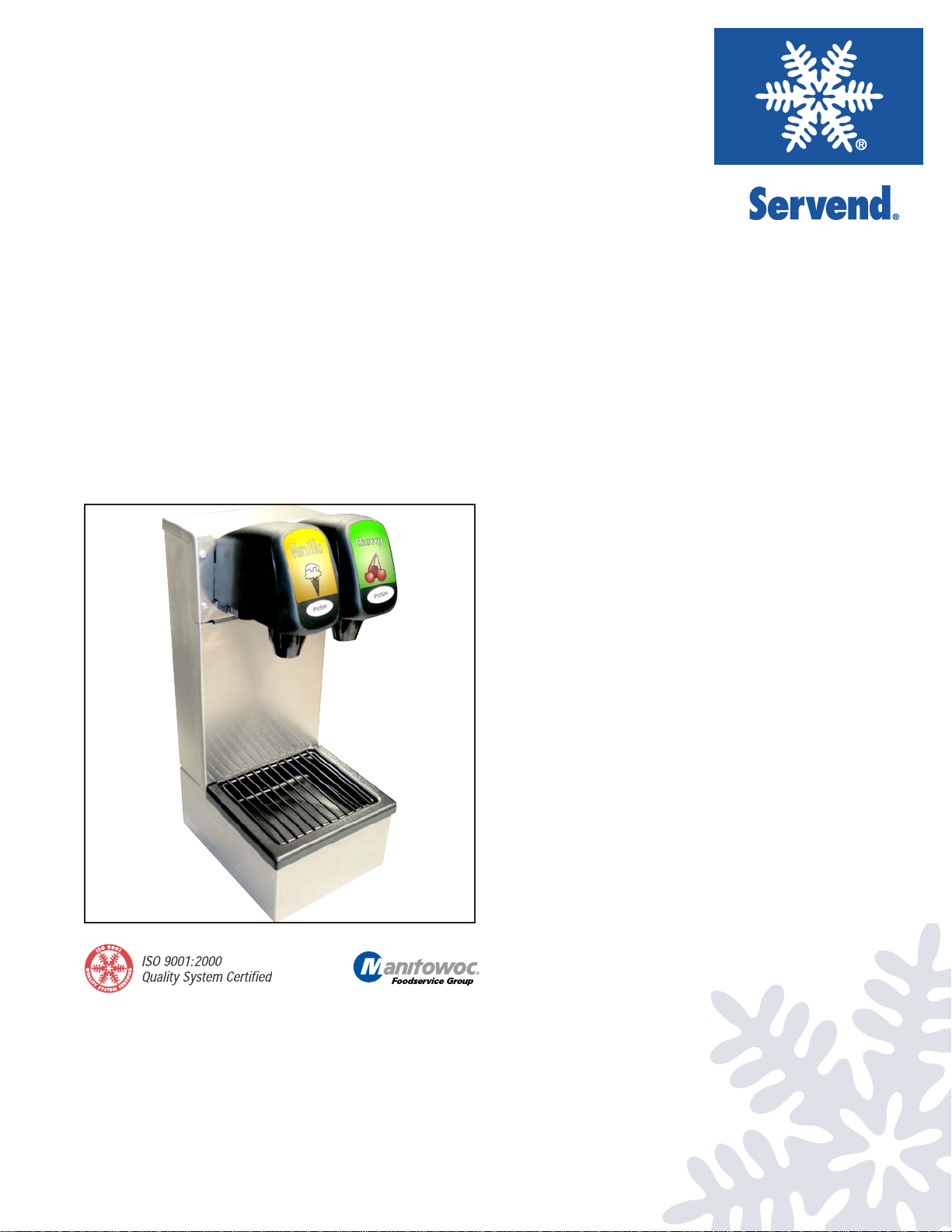
BEVERAGE & FLAVOR
SHOT TOWERS
INSTALLATION & SERVICE GUIDE
Part Number 5030763
Manitowoc Beverage Equipment
2100 Future Drive Sellersburg, IN 47172-1868
Tel: 812.246.7000, 800.367.4233 Fax: 812.246.9922
www.manitowocbeverage.com
In accordance with our policy of continuous product development and
improvement, this information is subject to change at any time without notice.
September 27, 2006 REV2
Page 2

Page 3

FOREWORD
Manitowoc Beverage Equipment (MBE) developed this manual as a reference guide for the owner/
operator , service agent, and installer of this equipment. Please read this manual before installation
or operation of the machine. A qualified service technician should perform installation and startup of this equipment, consult the Troubleshooting Guide within this manual for service assistance.
If you cannot correct the service problem, call your MBE Service Agent or Distributor. Always have your model and
serial number available when you call.
Your Service Agent___________________________________________________________________
Service Agent Telephone Number ______________________________________________________
Your Local MBE Distributor ___________________________________________________________
Distributor Telephone Number _________________________________________________________
Model Number ______________________________________________________________________
Serial Number _______________________________________________________________________
Installation Date _____________________________________________________________________
UNPACKING AND INSPECTION
Note: The unit was thoroughly inspected before leaving the factory. Any damage or irregularities should
be noted at the time of delivery.
WARRANTY INFORMATION
Consult your local MBE Distributor for terms and conditions of your warranty. Your warranty specifically
excludes all beverage valve brixing, general adjustments, cleaning, accessories and related servicing.
Your warranty card must be returned to Manitowoc Beverage Equipment to activate the warranty on this
equipment. If a warranty card is not returned, the warranty period can begin when the equipment leaves
the MBE factory .
No equipment may be returned to Manitowoc Beverage Equipment without a written Return Materials
Authorization (RMA). Equipment returned without an RMA will be refused at MBE’ s dock and returned to
the sender at the sender’s expense.
Please contact your local MBE distributor for return procedures.
Page 4

TABLE OF CONTENTS
FOREWORD ........................................................................................................ 3
UNP ACKING AND INSPECTION......................................................................... 3
WARRANTY INFORMATION ............................................................................... 3
SAFETY ...............................................................................................................5
IMPORT ANT SAFETY INSTRUCTIONS ........................................................................... 5
CARBON DIOXIDE WARNING......................................................................................... 5
QUALIFIED SERVICE PERSONNEL................................................................................ 5
SHIPPING, STORAGE, AND RELOCATION ..................................................................... 5
ADDITIONAL WARNINGS................................................................................................ 5
GROUNDING IN STRUCTIONS........................................................................................ 6
INSTALLATION .................................................................................................... 7
UNIT INSPECTION ........................................................................................................... 7
PRE-INSTALLATION CHECK LIST .................................................................................. 7
UNIT INST ALLATION ....................................................................................................... 8
UNIT INST ALLATION ....................................................................................................... 9
OPERATION ........................................................................................................9
ST ARTING YOUR FLAVOR SHOT BEVERAGE SYSTEM ............................................... 9
BEVERAGE VALVES ....................................................................................................... 9
COUNTERTOP MEASUREMENTS ................................................................................ 10
USER MAINTENANCE ...................................................................................... 10
PREVENTATIVE MAINTENANCE .................................................................................. 10
CLEANING AND SANITIZING INSTRUCTIONS ..............................................................11
DAILY CLEANING ...........................................................................................................11
MONTHLY SANITIZING...................................................................................................11
BAG-IN-BOX .................................................................................................................. 12
INDEX.................................................................................................................18
Page 5
Installation and Service Manual
SAFETY
IMPORTANT SAFETY INSTRUCTIONS
Carefully read all safety messages in this manual. Learn how to operate the Flavor Shot Beverage Towerunit properly. Do not allow anyone to operate the unit without proper training and keep
it in proper working condition. Unauthorized modifications to the Flavor Shot Beverage Tower
may impair function and/or safety and affect the life of the unit.
CARBON DIOXIDE WARNING
DANGER: Carbon Dioxide (CO2) displaces oxygen. Exposure to a high concentration of CO2 gas
causes tremors, which are followed rapidly by loss of consciousness and suffocation. If a CO2 gas leak
is suspected, particularly in a small area, immediately ventilate the area before repairing the leak. CO
lines and pumps should not be installed in an enclosed space. An enclosed space can be a cooler or
small room or closet. This may include convenience stores with glass door self serve coolers. If you
suspect CO2 may build up in an area, venting of the B-I-B pumps and / or CO2 monitors should be utilized.
QUALIFIED SERVICE PERSONNEL
WARNING: Only trained and certified electrical and plumbing technicians should service this unit.
All wiring and plumbing must conform to national and local codes.
2
SHIPPING, STORAGE, AND RELOCATION
CAUTION: Before shipping, storing, or relocating this unit, syrup systems must be sanitized. After
sanitizing, all liquids (sanitizing solution and water) must be purged from the unit. A freezing environment causes residual sanitizing solution or water remaining inside the unit to freeze, resulting
in damage to internal components.
ADDITIONAL WARNINGS
Installation and start-up of this equipment should be done by a qualified service technician. Operation,
maintenance, and cleaning information in this manual are provided for the user/operator of the equipment.
Save these instructions.
5
Page 6
Installation and Service Manual
SAFETY
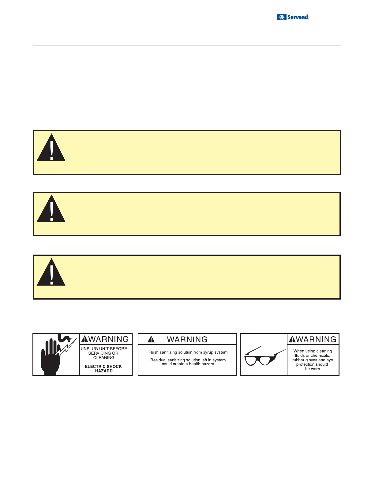
GROUNDING IN STRUCTIONS
WARNING: Risk of electrical shock. Connect to a properly grounded outlet only.
This appliance must be grounded. In the event of malfunction or breakdown, grounding provides
a path of least resistance for electric current to reduce the risk of electric shock. This appliance is
equipped with a cord having an equipment-grounding conductor and a grounding plug. The plug
must be plugged into an appropriate outlet that is properly installed and grounded in accordance
with all local codes and ordinances.
DANGER – Improper connection of the equipment-grounding conductor can result in a risk of
electric shock. The conductor with insulation having an outer surface that is green with or without
yellow stripes is the equipment grounding conductor. If rep air or replacement of the cord or plug
is necessary , do not connect the equipment-grounding conductor to a live terminal. Check with a
qualified electrician or serviceman if the grounding instructions are not completely understood, or
if in doubt as to whether the appliance is properly grounded. Do not modify the plug provided with
the appliance – if it will not fit the outlet, have a proper outlet installed by a qualified electrician.
WARNING – When using electric appliances, basic precautions should always be followed, including the following:
a) Read all the instructions before using the appliance.
b) To reduce he risk of injury, close supervision is necessary when an appliance is used
near children.
c) Do not contact moving parts.
d) Only use attachments recommended or sold by the manufacturer.
e) Do not use outdoors.
f) For a cord-connected appliance, the following shall be included:
• Do not unplug by pulling on cord. To unplug, grasp the plug, not the cord.
• Unplug from outlet when not in use and before servicing or cleaning.
• Do not operate any appliance with a damaged cord or plug, or after the appliance
malfunctions or is dropped or damaged in any manner. Return appliance to the
nearest authorized service facility for examination, repair , or electrical or mechanical
adjustment.
g) For a permanently connected appliance – Turn the power switch to the off position
when the appliance is not in use and before servicing or cleaning.
h) For an appliance with a replaceable lamp – always unplug before replacing the lamp.
Replace the bulb with the same type.
i) For a grounded appliance – Connect to a properly grounded outlet only. See Ground-
ing Instructions.
SAVE THESE INSTRUCTIONS
6
Page 7

Installation and Service Manual
INSTALLATION
UNIT INSPECTION
Thoroughly inspect the unit upon delivery. Immediately report any damage that occurred during transportation to
the delivery carrier. Request a written inspection report from a claims inspector to document any necessary claim.
PRE-INSTALLATION CHECK LIST
When installing any system, first make sure the major components are available. Generally the major components
necessary for an installation are:
Pre-mix system:
CO
regulator set
2
Product connectors for Figal tank
Gas connectors for Figal tank
Beverage dispenser
Beverage tubing
CO
tank
2
Figal beverage tanks
Stepless (Oetiker) clamps
Chain for CO
tank
2
Post mix system:
CO
regulator set
2
Beverage dispenser
Beverage tubing
CO
tank
2
Carbonator
Stepless (Oetiker) clamps
Chain for CO
tank
2
B-I-B System also:
B-I-B connectors
B-I-B regulator set
B-I-B rack
B-I-B syrup boxes
Double Check:
Do you have enough space to install the dis-
penser?
Also consider the location of the following items before
installation:
Water line Drain
Figal system also:
Syrup connectors for Figal tank
Gas connectors for Figal tank
Figal syrup tanks
Is the countertop level?
Power outlet Heating and air conditioning ducts
7
Page 8

Installation and Service Manual
FIGURE 1
INSTALLATION
UNIT INSTALLATION
1. Carefully remove the tower from the shipping container and check for freight damage. Any damage
should be noted at the time of delivery and reported
to the carrier. DO NOT DISCARD ACCESSORIES
BAG.
2. Drain line:
a. If a drain line is desired, carefully remove end
from 3/4" (1.905 cm) horizontal drain fitting (See
figure 2) on drain pan and attach a 3/4" (1.905
cm) insulated drain line of sufficient length to
reach drain. Assure that drain line slopes toward
drain 1/8" per foot (0.5cm per m) or per local plumbing codes.
b. If no drain line is desired, do not remove end of 3/
" (1.905 cm) drain fitting. Drain pan will have to
4
be removed and emptied manually as required.
Post Mix Beverage V alve Instructions for
Models 2703405 and 2703406:
1. Plumb the tower.
a. Plumb the syrup lines using the two (2) pre
plumbed tower syrup line connections with 1/
"(.635cm) by 3/8“(.95cm) connectors to 3/
4
“(.95cm) syrup line.
8
b. Attach syrup lines to syrup connection on syrup
pump.
c. Plumb the water/soda line using the 1/4"(.635cm)
pre plumbed tower water line connection with 1/
"(.635cm) X 3/8“(.95cm) connector to a 3/8“(.95cm)
4
water line.
d. Attach water line to water source, carbonated wa-
ter or plain water as required.
2. Select the tower location.
3. Using the enclosed template (P.N. 5012434), mark
cut outs for syrup/water lines, drain line (if used) and
mounting screws.
4. Cut the holes for the incoming water, syrup, and (if
used) drain lines.
5. Mount the tower and secure with the two (2) enclosed
#8 X 3/4" (1.905 cm) screws.
6. Plug the transformer butt connector into the tower.
Plug the transformer wall plug into a standard duplex
outlet.
7. Set syrup pump pressure on regulator according to
line run length and syrup viscosity.
8. Turn on water flow to valves.
9. Turn key to “ON” position.
10. Set the valve flow rates to between 1.5 oz (44 cc) /
second and 3.0 oz (88 cm) / second and brix the
beverage valves to the proper ratio after attaining
normal beverage dispense temperature.
11. Check for water and syrup leaks.
8
Page 9

INSTALLATION
UNIT INSTALLATION
Flavor Shot Valve Instructions Models 2703315 and 2703329:
1. Plumb the unit.
a. Plumb the syrup lines using the two (2)
pre plumbed tower syrup line connections with
"(.635cm) X 3/8“(.95cm) connectors to 3/8“(.95cm)
4
syrup line.
(See Figure 2)
b. Attach syrup lines to syrup connection on syrup
pump.
c. No water line connection is used on Flavor Shot
Towers.
2. Select the tower location.
3. Using the enclosed template (P .N. 5012434), mark
cut outs for syrup lines, drain line (if used), and
mounting screws.
4. Cut the holes for the incoming syrup and drain lines
(if used).
Drain Fitting
FIGURE 2
5. Mount the tower and secure with the two (2) #8 X 3/
" (1.905 cm) screws.
4
6. Plug the transformer butt connector into the tower.
Plug the transformer wall plug into a standard duplex outlet.
7. Set syrup pump pressure on regulator according
to line run length and syrup viscosity.
8. Turn key to “ON” position.
9. Set the syrup flow rate to 1 oz (30 cc) /sec ond and
test run the valves.
10. Check for syrup leaks.
Installation and Service Manual
1
/4"(.635cm)
1
/
OPERATION
STARTING YOUR FLAVOR SHOT BEVERAGE SYSTEM
Upon completion of the beverage dispenser and / or system installation, all tubing, dispenser , and system components must be cleaned and sanitized prior to use.
NOTE: At installation equipment, dispensers, and tubing get moved through many environments, dirt, dust, chases,
insulation, drywall, etc. It is an important procedure and best practice to address cleaning to deliver the best quality
drink to your customer.
Clean and sanitize the water and syrup circuits according to instructions provided in this manual. Clean and sanitize the dispenser components according to instructions provided in this manual. Seal to counter top when no legs
are used with the unit. Consult and use local health codes if a discrepancy occurs between this manual and your
local health codes.
BEVERAGE VALVES
Post-mix beverage valves are designed to precisely meter the flow of both water and syrup to obtain the proper
mixing ratio. The syrup and soda water components of the post-mix beverage are mixed as they leave the beverage valve.
9
Page 10

Installation and Service Manual
OPERATION
COUNTERTOP MEASUREMENTS
8.375"
21.27 cm
7.1875"
18.23 cm
17.70"
44.958 cm
16.875"
42.86 cm
2.375"
6.032 cm
USER MAINTENANCE
8.9375"
22.70 cm
PREVENTATIVE MAINTENANCE
Preventative maintenance is a vital part of keeping your Servend dispenser in top condition. Following the guidelines
below will assist you in continued trouble free operation of your unit. Contact MBE at 1-800-367-4233 for more
information about our ProActive Maintenance Program.
1. Conduct daily maintenance of the machine.
2. Perform monthly maintenance of the machine.
10
3. Perform periodic maintenance and sanitizing of beverage system.
4. Do not allow the dispenser to sit for prolonged periods of non use.
Page 11

Installation and Service Manual
Valve nozzle
and diffusers
Splash panel
Drain pan
Grid
USER MAINTENANCE
CLEANING AND SANITIZING INSTRUCTIONS
NOTE: Scheduled cleaning must be in compliance with local health codes. This cleaning schedule is a recom-
mendation. Cleaning procedures may vary according to local health codes.
DAILY CLEANING
CAUTION: Use only warm soapy water to clean the exterior of the dispenser. Do not use
solvents or other cleaning agents. Do not pour hot coffee into the drain pan. Pouring hot coffee
You will need clean warm water to wash and rinse with,
mild non-abrasive soap and a clean cloth to clean the
following:
• Drain pan
• Grid
• Splash panel
• Valve nozzles
• Diffusers
1. Lift up the grid and remove it from the drain pan
2. Using mild soap, warm water and clean cloth, wash
the drain pan and splash panel. Then rinse with
clean, warm water. Allow plenty of warm water to
run down the drain to remove syrup residue that
can clog the drain opening.
3. Wash the grid, then rinse with clean warm water.
Place the grid back in the drain pan.
4. Wash all exterior surfaces of the unit with warm
water and a clean cloth. Wipe again with a clean,
dry cloth.
5. Turn nozzle clockwise to the stop. Pull the nozzle
downward to remove. Grasp diffuser and pull downward to remove.
6. Clean both the nozzle and diffuser with soap and
water to remove syrup residue. (A sof t bristle brush
can be used).
7. Rinse nozzle and diffuser with warm, clean water.
8. Replace diffuser in the valve body . Position nozzle
and turn counter clockwise to the stop.
Mix a sanitizing solution of 1/2 ounce liquid, unscented bleach (5.25%Cl Na O concentration) with a gallon of water,
to supply 100 PPM of available chlorine. Using this solution and a clean cloth or soft bristle brush, sanitize the parts
mentioned in the daily cleaning procedure. Allow parts to air dry and then re-assemble.
11
MONTHLY SANITIZING
Page 12

Installation and Service Manual
USER MAINTENANCE
BAG-IN-BOX
You will need: Three clean, empty five-gallon buckets to
be used for the rinse, detergent and sanitizing.
1. Disconnect the bag-in-box connectors.
2. Prepare the following in three clean buckets:
a. Rinse bucket - fill bucket with clean tap water
b. Detergent bucket - mix mild non-abrasive de-
tergent with warm water as recommended by
the detergent manufacturer.
c. Sanitizing bucket - mix a solution of 1 ounce of
unscented household bleach (5.25% Cl Na O
concentration) with two gallons of tap water.
The mixture should supply 100 PPM of available chlorine.
3. Remove the cap located opposite the tubing connection on the bag-in-box connector. Alternate: use
old BIB bag.
4. Place bag-in-box connector in the rinse (step 2A).
Draw clean tap water through the system and out
the beverage valve until all syrup is flushed from
the system.
5. Place bag-in-box connector in the detergent bucket
(step 2B). Draw detergent solution through the system and out the beverage valve for 2 minutes. Then
allow the remaining detergent stay in the system
for 5 minutes.
6. Remove the valve nozzles and diffusers, as described in the daily cleaning instructions. Using a
clean cloth or a soft bristle brush, scrub the nozzle,
the diffuser, the bottom of the valve and the cup
lever, if applicable.
7. Place the valve diffusers and nozzles in sanitizing
solution for 20 minutes, then replace them on the
beverage valve.
8. Place bag-in-box connector in the sanitizing bucket
(step 2C). Draw sanitizing solution through the system and out the valve for 10 minutes. Allow the
sanitizing solution to remain in the system for a minimum of 20 minutes.
9. Replace the plastic cap opposite the tubing connection on the bag-in-box connector (or remove
bag if alternate old BIB bag is used).
10. Reconnect the bag-in-box connector to the syrup
bag-in-box.
1 1. Draw syrup through the system and out the bever-
age valve until all sanitizing solution is flushed from
the system.
12. Repeat the above steps for each syrup circuit of
each beverage valve or follow this procedure with
any number of valves concurrently.
12
Page 13

Page 14

Page 15

Page 16

Page 17

Page 18

INDEX
B
brixing ....................................... 3
C
Carbon Dioxide ......................... 5
CAUTION................................ 10
claims........................................ 7
Cleaning.................................... 3
CO2........................................... 4
CO2 monitors............................ 4
D
damage ................................ 3, 7
delivery................................. 3, 7
distributor .................................. 3
Drain ......................................... 7
ducts ......................................... 7
F
FOREWORD ............................ 3
I
INSPECTION ............................ 3
inspection.................................. 7
INSTALLATION ................7, 8, 9
Installation Date ........................ 3
irregularities .............................. 3
L
location ..................................... 7
M
MBE .......................................... 3
Model Number .......................... 3
modifications............................. 5
O
Operation .................................. 5
P
Power outlet .............................. 7
Q
Qualified Service Personnel ..... 5
R
Relocation ................................. 5
return procedures ..................... 3
S
SAFETY ............................... 5, 6
sanitizing ................................... 4
Serial Number........................... 3
service assistance .................... 3
Service Personnel..................... 5
Shipping .................................... 5
Shipping, Storage, Relocation .. 5
soapy water............................. 10
solvents................................... 10
start-up...................................... 5
Storage ..................................... 5
U
Unit Inspection .......................... 7
UNPACKING............................. 3
W
Warning..................................... 5
WARRANTY INFORMA TION ... 3
Water line.................................. 7
water-to-syrup ratio. See brixing
Page 19

Page 20

Manitowoc Beverage Equipment
2100 Future Drive Sellersburg, IN 47172-1868
Tel: 812.246.7000, 800.367.4233 Fax: 812.246.9922
www.manitowocbeverage.com
In accordance with our policy of continuous product development and
improvement, this information is subject to change at any time without notice.
5030763 September 27, 2006 REV2
 Loading...