

Page 1
The
basics
To the owner
your
What
Salety
Post Off ice
Which receivers can
Switching on
Fitting
Charging the transmitter and
Connecting the
Standard
What moves which
Fault finding:
Flying
What controls
Reversing servo direction
Altering control surlace travels....
Cars and
What
system can do
................. ................-...... 3
regulations .......................................... 3
you
for
the cryslals
receiving
channel assignments:
possible
first time
the
...............
and
sources of error .................
fixed-wing model aircraft
what?
(stick
Trucks
controls
what?...................................-.......... 8
.............................
.....................................
.............................. 3
use?
receiver
system components......
how? ..........................
mode) .........................
(servo
batteries....
reverse) ............
Boats
What controls what?.............................................. I
Example: twin-motor boat
How to set up the transmitter
Adiusting servos
How do
Servo centre and travel adjustment
Servo
Duaf Rates
The function:
Installing
Setting
Usino
you
adjust servos?
reversing..
(Menu
and
Dual Rates
channels 8 and 9 as switched channels
(Menu
"now
more. now less" ....................
connecting Dual Rates switches
travel
..................................... 8
................................ I
point
SEFVO)
................................. 10
.................... 1 0
..................... 11
point
DR Mt'I)
........ 12
2
2
5
5
6
6
7
12
... 12
.... 13
MULTlnaut
The
Safety
Specif
How
What has to be done at the transmitter?.............
How is the MULTlnaut top receiver
How do
Examole:
Connecting relays and motors to outputs A to
Suppressing electric
Example: boat functions.....
Connecting end-point switches....,.......................
Installing the MULTlnaut top system
Long connecting |eads ..................
What
Modifying
How
Are
How are sticks and other controls calibrated?
How is
notes
ications .....
go
to
installed in
you
system
truck
in
an existing transmitter..........
accessories are available?
the transmitter
can the
receiver
the transmitter controls connected correctly?
the stick
Information
do
you
How
Teacher/Pupil operation - a
lnformation
fop system
it ...............
about
model?
the
connect the MULTlnaut top
in
model?
the
functions....
motors ....
transmitter
outputs be assigned?
ratchet installed?
sticks
and
applying to
all transmitter
change the
applying to
fuse? ............................. 28
great
idea1..... .......... 28
the
module
variants
F .
.....
20
20
20
21
22
22
23
23
24
25
25
26
10
27
27
EUROPA mc 1005
Whafs
Swapping the sticks
different?.
round .................. ................ 29
.................... 28
Receiving system, care of transmitter,
servtce
Arrangement of battery, servos and
Receiver
Interf
Range testing
Servo
Airborne
Diagnosis
Care of the transmitter
The transmitter battery ........................................ 31
MULTf PLEX HOTL|NE............ ........................... 32
Optional extras, accessories
tips.......................................................
erence suooression
magneto / electronic
tips ................................ 30
power
supp1y......................................... 31
(closed
loop) operation ....................... 31
with
ignition ..........................
receiver......
..........................
............
........................... 32
30
30
30
30
31
Overview of
GB-1-
functions
33
Page 2
To the
owner
What
your
system
can
do
customer,
Dear
and
fellow-modeller,
new EUROPA
Your
is designed
ideal
have carefully
We
features,
overwhelmed
Nevertheless
you can use
when
you
lf
working
system
top
operation.
control
potentiometers. The
tt4)o
with one
We are
system
that
)tou
hobby and
Yours sincerely,
specifically
introduction
to ensure that
by a
the set
it to tontrol
the time
are
modules,
very
from
comes.
an enthusiast
model,
will open
The transmitter
transmitter
pleased
tfte MULTIPLEX
many hours
haw
with our
radio control
mc
to
to our
fdscinating
selected
the beginner
perplering spread
plenty in reserve, so
has
quite
for
the newly
up
for
each containing
nautic version
module
you
that
transmitter.
the beginner'
form
a range of
complex
multi-function
the
developed
you
('an
as standard.
have det'ided
stable
pleasure in
of
hobhy.
essential
will not be
offacilities.
MULTlnauf
a broad
be
fitted
switches
six
,
transmitter
s
that
models
of
field
with r**o
and
is supplied
a
on
hope
and
your
The standard
.
9 channels
.
3 model
.
Menu system
.
Duaf
(switchable
.
X-MIX
(e.9.
.
Y-Mlx
switchable
.
Six-step
.
Battery
Optional
.
Extra transmittet
(sliders,
.
MULTlnaut top
models
.
Neckstrap system
Special
.
QUICK-SELECT
selecting
.
Diagnosis
for interf erence-f
O EUROPA
O ootional
memories
Rate on channels 1 and
(freely
V-tail models)
(f
reely assignable
(e.9.
battery
monitor wiwth audible
extras
2- or 3-position
features
and asstgning
(closed
mc
switch
functions
(control
servo
functions)
O
for
setting
travel)
assignable
combi-switch)
level indicator
channels
system
the fast
loop) operation
ree testing
1005, 1020 and
reouired!
up and
two-way
one-way
switches)
for multi-function
method ol
functions
programming
2 @
mixer)
alarm
nautic onlyl
O
mixer), O€
working
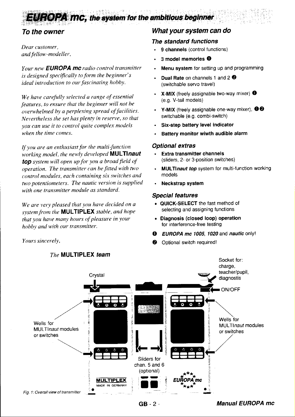
Wells for
MULTlnauf
swilches
or
1: Oveellview
Fig.
MULTIPLEX
flre
modules
of ttansmtttel
team
crystar
Th--,-*FoN/oFF
--Effi-
trl
iEEffi
:.
,;r
5 and 6
chan.
(optional)
-
-
:no:[1,'o''
y7iilü133f."
EEFEe
:
.***.
"ä?:jt"
.
GB-2
Manual
EUROPA
mc
Page 3
SAFETY
Radio-controlled
Even
property
suggestions and are
They
are certainly
hobby.
at all times. You will save
trouble.
Insurance
Operating radio-controlled models
aircratl - does
greatest
the
must
insurance is one
modelclub,
through the
Club colleagues will soon fill
insurance.
Prevention - better than cure
Safety begins
model.
points
are
mooer.
The
biggest contribution to safety is one
operating
carefully
to be complete, and the
importance. lt is
you
what
.
.
.
.
'
.
.
.
models are capable of causing damage
small
and even to
Please read
care, and
be considered a basic essential.
whereby
nationalorganisation
Control surface
which later
your
and responsibly. The following list is not meant
can and
Check
surf ace
Charge
the
before
Carry out regular range checks
the section covering the
Do not
certain thal other
using the same channel.
Never run down
batteries close to the limit of their capacity.
Note
capacity until they have completed several
charge / discharge cycles.
Each
flight,
Are
Stick
Stick back: elevator up etc.
Always
extent before
Use original
accessories exclusivelvl
plug-in
proper
you
switch on
also that
time
check each
the servo travels and directions correct?
left:
models
people.
provided
not meant
points
these
involve
when
linkages regularly.
your
exlend
certain
for
this
possible
radio
only
should
manner
fly
you
conlrol surface / steering
solution. A second
suitable coverwill usually be available
you
are designing and building
linkages, radio
play
a major role in
control system and
points
intended
do.
conneclions, servos and control
transmitter and receiver
and check the state of charge
(use
a battery
your
modellers
your
new
batteries do
switch memories, and before every
function
your
transmitter aerial to
you
start a
MULTIPLEX
not
are
The following notes
with
the best of intentions.
to spoil
yourself
reason
you
transmitter unless
transmitter and
your pleasure
and follow our
much expense
-
risks,
even
third
to which the club
in
how
on
are not listed in order
give you
to
testeo.
receiving
close bv are
not
carefully.
flight.
crystals and
toys!
are
in
guidelines
and
especially
when
party
Private liability
best to obtain
installation etc.,
the safety of
you
can make: by
a
as described
system.
achieve full
left
model
you
take
insurance
join
is
to
belongs.
your
your
your
model
few
ideas of
battery
you
are
not
receiver
its full
in
in
The legal
Radio
controlled
operale on the
to
just
models,
includes
boats of all types.
the
model
copters). Radio
category, and operate at 49 MHz where
orovided
The trequency
are shown below:
a
Since the
Band radio
also allocated
controlled
MHz
MHz band.
Please note
models, and
aircraft. Model
MHz
MHz
of
As of 1 January 1981 model
exempted from the licensing requirements
Telegraphy Act 1949. This
is required
lf
and lhe
licensing,
The Low Power
Radiocommunications
Room 712, Waterloo Bridge House,
Waterloo Road. London.
Teleohone:
and those
aircraft and rotary-wing machines
Frequency in MHz
26.960 to 27.280
34.995 to 35.255
40.665 to 40.955
458.500
band
band. and model aircraft must not
band.
you
need lurther information
side
ground
model cars, trucks
for low
bands available for radio controlled models
to
26127 MHz
and other users,
to telemeüy and other devices, radio
models
(usually
that 40 MHz is
34135
car and boat operators must not use the
to operate RC
regulations which
please
071 215 2058
Which receivers
Tne
EUROPA
You can use
channels.
mean
that
A MICRO
nine
channels and can therefore be used with
PA mc
All receivers in
used:
Older receivers which
lf in any
MULTIPLEX HOTLINE.
transmitter.
e.g.
Micro
doubt, ask
rnc
any
To
decode nine channels does not necessarily
nine
receiver
5t7@ceiver has
the cu(ent MULTIPLEX ranqe
FM DS, Mini
9, Uni 9,
(tot
the U.K. only)
models
which
The
controlled toys come into a different
oower
459.500
contact:
Radro Section
are of two types - those which
water, known
or on
operate
and buggies, and also
second encompasses fixed-wing
radio
devices.
band is also allocated for
and the
generally
are
known simply
dedicated solely to surface
MHz is
dedicated solely to model
simply means that no licence
equipment
exempt model control from
Agency
SEl 8UA
can
transmitter
PPM receiver which
outouts are available.
only seven outputs, butdecodes
Micro
9,
can also be used:
Mini 7,
your
Uni 4
specialist dealer or the
"surface"
as
in
the air. The
(mainly
a small band
Use
General
Air
Surface
General
458/459 MHz
operated on the 34/35
MHz)
as 35
flown
be
control equipment was
of the
in
the UK.
on technical restrictions,
you
use?
lransmits
5/7
nine
can decode nine
group
first
model
heli-
Citizens
band is
and the
on the
Wireless
channels.
EURO-
the
can be
is
40
35
40
GB-3- Manual
EUROPA mc
Page 4
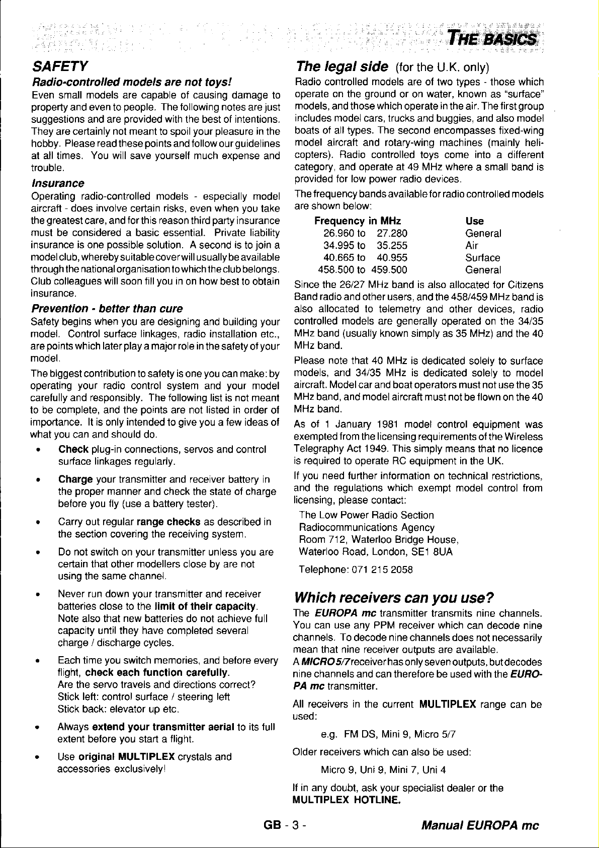
crystals
Fitting
Plug the
The transmitter
the channel
The
next to the
the
crystals
number.
receiver
crystal
channel
crystal
into the
has a blue
has a
number
transmitter
yellow{inted
(see
and
sleeve
receiver
also
receiver.
letter
and a
sleeve
instructions)
and
"S"
letter
a
printed
"E"
next to
printed
good
is a
This
must bear
Charging
The standard
charged
Plug-type
the transmitter
hours.
rapid-charging
When
your
system
COMBI-CHARGER
and
Connecti
system
To
out the
try
receiving
it in a
install
getting
of
svstem
lime to
the same
the
batteries
NORMAL
at a
mains
and
we recommend
MULTIPLEX
any
ng
the
components
system
system
used
and
on the
model.
your
to
works.
how it
frequency
fix the
number as
the crystals
transmitter
have a capacity
rate or
charger
receiver
do
receiving
you
This
new radio
a FAST
V
230
batteries
not exceed
the
(mains 230V)
charger
rapid
before
easiest
the
connect
control
should
table
is
pennant
you
receiver
and
of
rate. lf
will be
a charge
you
fully charged
the
way
your
to
are using.
600
you
Order
current
Order
transmitter.
mAh and
use the
No. 14 5535
of 600
No. 14 5540
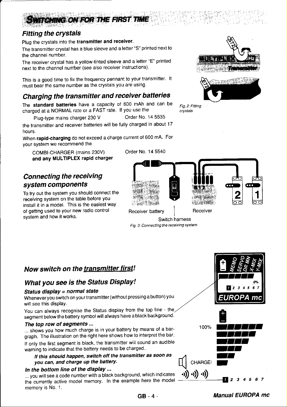
Receiver
Connecting
Fig. 3:
lt
batteries
can be
about
mA.
Switch
the
17
For
receiving
in
battery
Fig.2:Fitting
crystals
I
harness
system
Receiver
switch
Now
What
Status
Wheneveryouswitchonyourtransmitter(withoutpressingabutton)
will see
You
segment
The top
... shows
graph.
lf
warning
ln the
...
the
memorv
you
disPlaY
this
can always
below
row of
you
Tfre
first
the
only
to
ff this
you
can,
bottom
you
will see
currently
is No.
on thelIalillllüIllsil!
is
see
=
normal
display.
recognise
battery
the
segments
much
how
illustration
segment
indicate
should
that
happen,
charge
and
line of the
a code
active
number
model
1 .
on
Status
the
state
the
symbol
.'.
charge
right
the
is
black,
the battery
switch
uP the
display
with a black
memory.
DisPlaY!
Status
display
will always
your
is in
here shows
transmitter
the
needs to
off the
battery.
...
In
the
from the top
have a black
means
battery
background,
by
to interpret
how
will sound
be charged..
transmitter
which
example
here the
you
line - the
background'
bar-
of a
bar'
the
audible
an
as
soon
as
indicates
model
(
'rl)',t)',1)
GB-4.
100%
.ro"o'
g
-afaaf
-faaf
-fta
-aa
-a
-
2 s
o
Manual
6 7
4 s
EUROPA
mc
Page 5
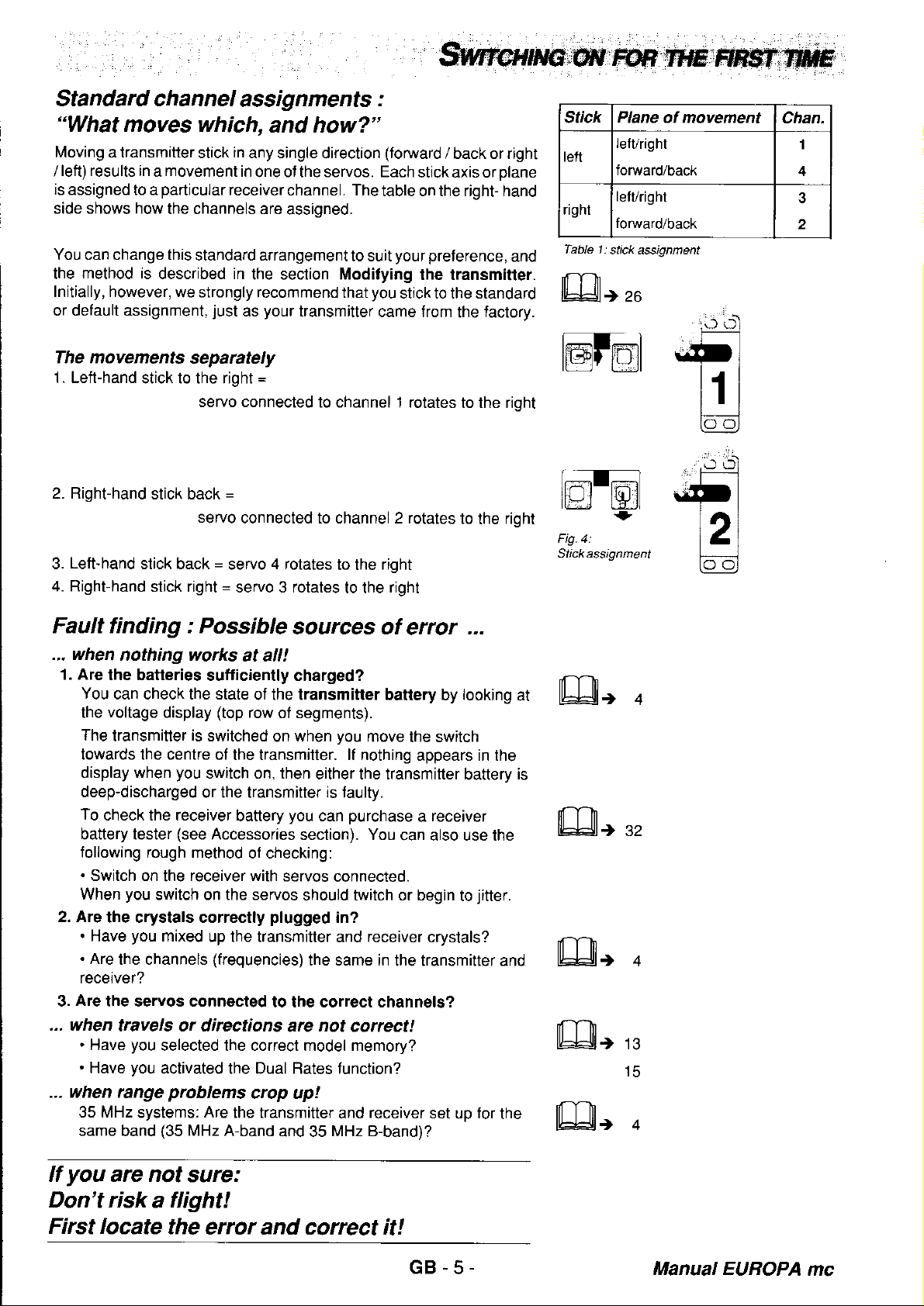
Standard channel
"What
Moving a transmitter
left) results in a movement
/
is
assigned to a
side shows how
You can change this
the
Initially, however,
or default assignment,
moves which,
particular
the channels are
method is
described in
we strongly recommend
in
stick
receiver
standard arrangement
just
assignments
:
and how?"
any single direction
in
one ot the servos. Each
channel. The
assigned.
the section Modilying
your
as
transmitter
(forward
table on the right- hand
to suit
you
that
came from
/ back or right
the
plane
and
factory.
stick axis or
your preference,
the transmitter.
stick to the standard
stick
lett
right
Table 1:
Plane
left/right
forward/back
lelvright
forward/back
stick assignment
)26
of movement
Chan.
1
4
3
2
The movements
1. Left-hand
2. Right-hand
Left-hand
3.
4. Righfhand
stick to the right
stick back
separately
servo connected
stick back
servo
=
stick right
=
=
connected to channel 2 rotates
4 rotates
servo
=
s€rvo 3 rotates
Fault finding : Possible
... when
1. Are
2. Are
3.
... when
... when range
nothing works
the batteries
You
can check the state
voltage
the
The
transmitter
towards the centre
display when
deep-discharged
To
check the receiver
baüery tester
tollowing
.
Switch on
When
.
Have
.
Are
receiver?
Are
.
Have
.
Have
35 MHz
same
rough method
you
switch on the servos
the crystals correctly
you
the channels
the servos connected
travels or directions
you
you
systems:
band
sufficiently charged?
display
is
switched
you
switch on, then
or the transmitter is taulty.
(see
receiver with
lhe
mixed
selected the correct model memory?
activated the Dual Rates function?
problems
Are
(35
MHz
at all!
of the transmiiler
(top
row
of segments).
on
of the transmitter. lf nothing
battery
Accessories
of checking:
servos
plugged
up the transmitter
(frequencies)
to the correct channels?
are
crcp up!
the transmitter
A-band
and 35
to channel 1 rotates
right
to the
right
to the
sources of
you
when
either the transmitter
you
section). You
purchase
can
connected.
should twitch or begin
in?
and
the same in
not
correct!
and
MHz B-band)?
error
battery by
move
the switch
appears in the
a
can also use the
receiver
receiver
crystals?
the transmitter and
set
to the rioht
to
the
...
looking
battery
receiver
jitter.
to
for
up
rioht
at
is
the
@f'ml
lr=r]-l=l
Itltj twil
Fig.4:
Stickassignment
lEß1,
lEß1,
lEQl,
t
o
o
t13
15
o
you
lf
are not
sure:
Don't risk a tlight!
First locate
the
error and correct it!
.5
GB
Manual EUROPA
mc
Page 6
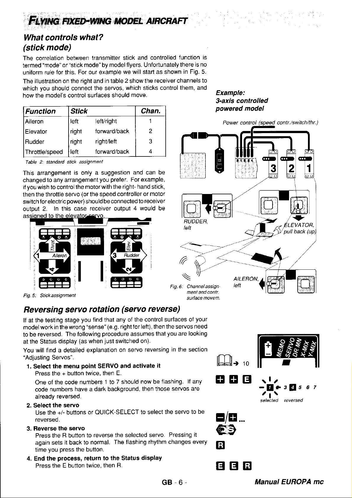
What controls
(stick
The correlation
termed
uniform
The
which
how the
mode)
"mode"
for
rule
illustration on the
you
should connect
model's conüol surfaces
what?
between
"stick
or
For our example
this.
right
Function Stick
Aileron
Elevator
Rudder
Throttle/speed
2:
Table
slandard
left lefuright
right
righl
le{t forward/back
stick assignment
lransmitter stick
mode"
model
by
in table 2 show the
and
the servos,
should
forward/back
righUleft
and controlled
flyers.
Unfortunately
we will start as shown
receiver channels to
which sticks control
move.
function
there
them, and
Chan.
1
2
3
4
is
is no
in Fig. 5.
Example:
s-axis controlled
powered
model
This arrangement
changed
you
if
then
switch
output
Fig. 5: Stickassignment
to any arrangement
wish to control
the throttle
forelectric
In
2.
Reversing
lf at the testing
modelwork
be
to
the Status
at
will find a detailed
You
"Adjusting
1. Select
Press the
One of
code
already
2. Select the
Use the
reversed.
Reverse the
3.
Press the R button
again
time
4. End the
Press the
in
reversed.
Servos".
the
the code
numbers
sets
you press
is only a suggestion
the
servo
oower)
this case
servo
stage
wrong
the
The following
display
menu
+ button twice, then
have a dark background,
reversed.
servo
+/- buttons
seruo
it
back
the button.
process,
E button twice,
you preter.
motor with the right
(or
the speed
should
receiver output
I
H
controller or
be connectedlo
ffiF
F*J.t
ruf
tl
ffi
rotation
you
find that any
"sense"
procedure
(as
when
explanation
point
SERVO and
numbers 1 to
or
QUICK-SELECT
reverse the selecled
to
to normal.
return to
lhen
(servo
(e.9. righttor left), then the servos
just
switched
on servo
E.
7 should
The flashing
the Status
B.
and can be
For example,
hand
stick,
motor
receiver
would
4
be
reverse)
of the control surfaces
assumes thai
on).
reversing
activate
now
then those servos
to select
servo.
rhythm changes
display
you
it
flashing.
be
the servo lo
Pressing it
of
looking
are
in
the section
lf
your
need
any
are
be
every
t10
ETEB
E/8...
@
tr
BB
rlu
-!r
/l\
selectecl
tlls a
reveßed
t
GB-6
Manual
EUROPA
mc
Page 7
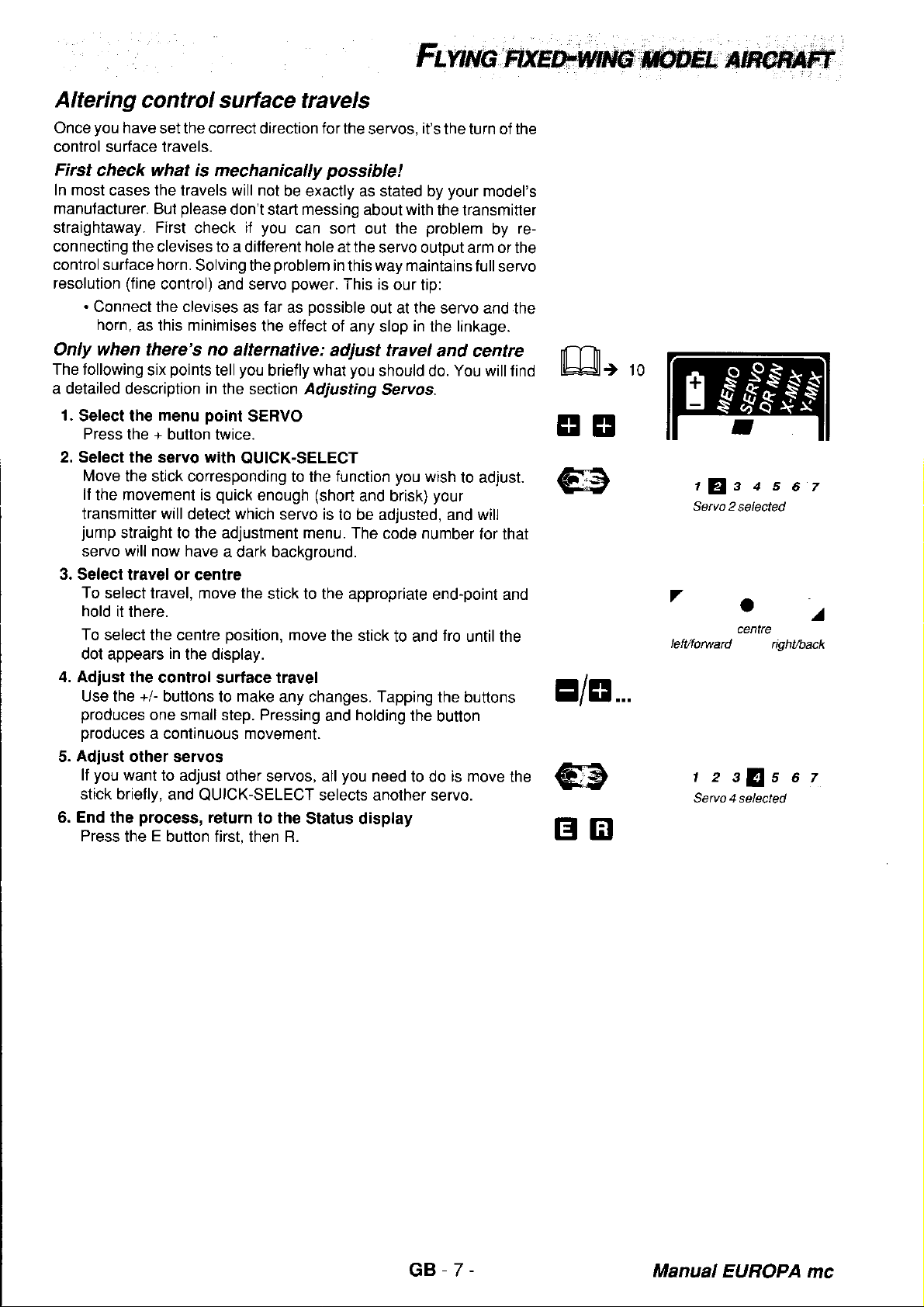
Altering
you
Once
conlrol surface travels.
First
In most
manufacturer.
straightaway. First
connecting the clevjses to
controlsurface horn.
resolution
.
Connect the clevises
Only when
The following
a detailed description in
1.
Select the
Press
2. Select the servo with
Move
lf
transmitter will
jump
servo
3. Select
To
hold
To
dot appears
4. Adiust the
Use the +l buttons
produces
oroduces
Adiust
5.
you
lf
stick brielly,
6. End the
Press
control surtace travels
have
set the correct direction for
check what is mechanically
cases the travels will not
please
But
check
Solving the
(fine
control) and servo
horn,
as this minimises
there's
six
menu
the + button twice.
the stick corresponding
the movement is
straight to the adjustment menu.
will
now have
travel or centre
select travel, move the
it there.
select the centre
control surtace travel
one small step. Pressing
a continuous movement.
other servos
want
process,
the E button first, then R.
no
points
tell
the section Adjusting
point
quick
detect
a dark backoround.
position,
in
the display.
to
to adjust other
and
QUICK-SELECT selects another servo.
return
lhe servos,
possihle!
be exactly as stated by
don't start messing
you
if
a difterent
as
alternative:
you
SERVO
QUICK-SELECT
which
make
can sort out the
hole
problem
power.
possible
far
as
the effect of
what
briefly
to the
enough
stick to the appropriate
servos, all
lo the
(short
servo is
move
any changes. Tapping
Status display
about
at the
in
this
This
any slop
adjust travel
you
function
and brisk)
to be adjusted, and will
The code number
the stick
holding
and
you
it's
the turn of the
your
model's
with
the transmitter
problem
servo output arm or
way
maintains lullservo
is our
tip:
out at the servo and
in
the linkage.
and centre
should
need
do.
Servos.
you
wish
end-point and
to and
the
to do
your
fro
the buttons
button
by
You will
to adjust.
for that
until the
is move
the
re-
the
the
find
t10
EE
E/8...
trtr
r
Setvo 2
7
'a
left/fowad
r z
SeNo4 selected
a s
Qls
selected
centre
slls a t
a z
ighLhack
a
GB-7.
Manual
EUROPA
mc
Page 8
What controls
For model boats and
power (throttle)
control
views on
In our examples
In this example
the
under
and
which stick should
.
The right-hand stick controls
system and
.
The left-hand stick
and operates
servos
works in the
menu
the
what?
cars the
we assume the
operates on channel
controls the
on channel
no mixers are used.
wrong direction,
SEBYO.
Doint
most important
control.
Here again there are
control
which function.
tollowing arrangement:
the sleering
3.
Dower
4.
lf
one
functions are directional
svstem
or other of
reverse il
many different
regarding the
Note
The EUROPA
is designed
The lefl-hand stick
or throttle
you
if
over
Inlormation
mc 1005
for directional control
is intended
control) and operates
wish;this
for the
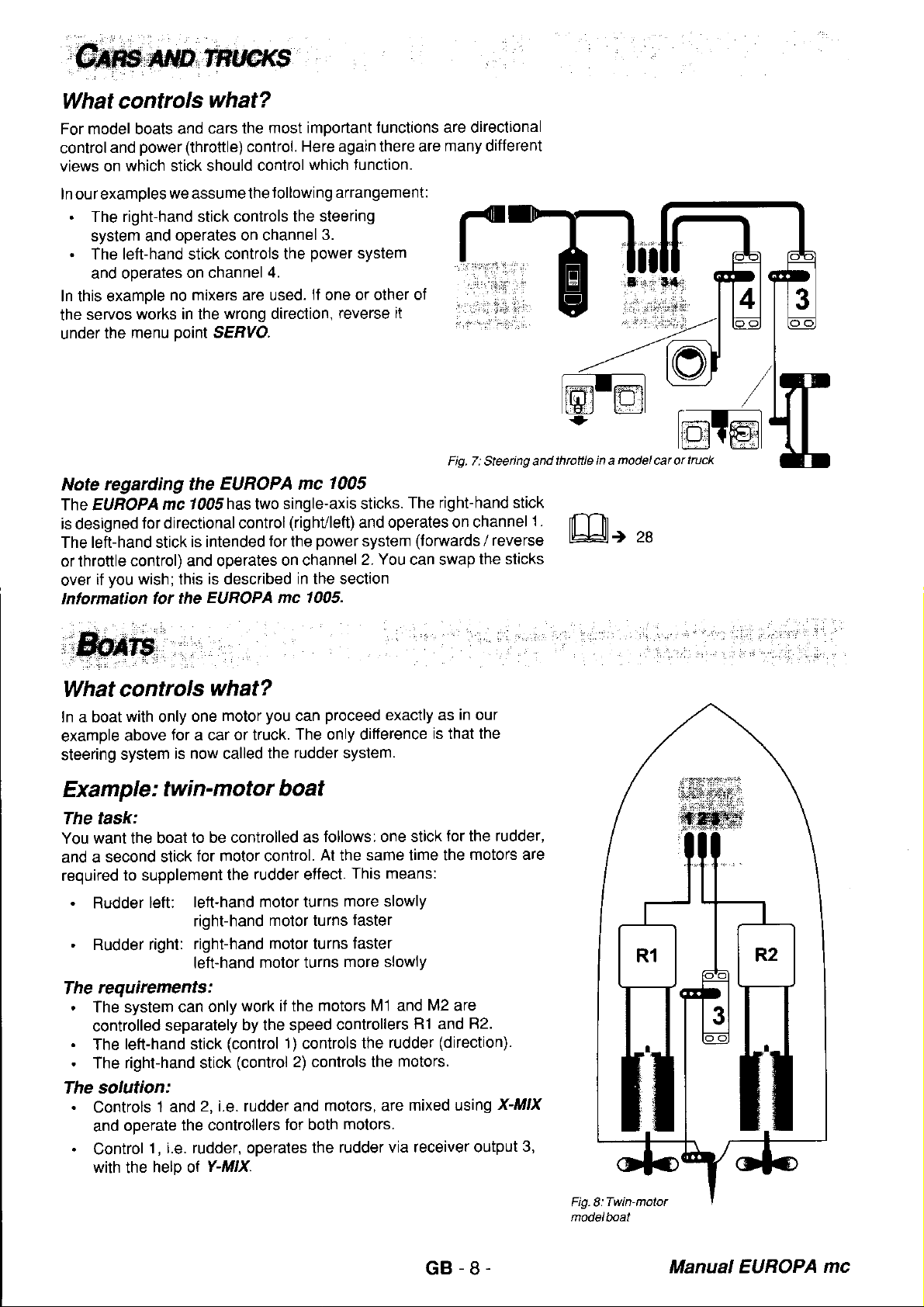
What controls
In
a boat
example
steering
with
above
system
Example
The task:
You want the boat
second stick
and a
required
.
.
The
.
.
.
The solution:
.
.
to supplement
Rudder
Rudder right:
requirements:
The system can
controlled
left-hand stick
The
The right-hand stick
Controls
operale
and
Control
with
the
one
only
for
a car
is now called
: twin-motor
to be controlled
for molor control.
left-hand motor turns
left:
right-hand
right-hand
left-hand
separately
2, i.e. rudder and
1 and
the controllers
1 , i.e. rudder, operates
help ot
EUROPA mc
has
is
described
EUROPA mc 1(n5.
single-axis sticks.
two
for
on channel
1005
(righvleft)
power
the
in the section
what?
you
motor
or truck.
the rudder system.
proceed
can
The only difference
boat
follows: one stick
as
At
rudder
the
work if the motors
only
by the speed
(control 1)
(control
Y-MIX.
effect.
motor turns
motor
lurns
motor turns
controls
2) controls the
molors, are
for both
the
Fig.7:Steeing and
right-hand stick
The
operates on channel
and
system
2. You can swap
the same
This means:
more slowly
faster
faster
more slowlY
controllers
the
motors.
rudder via receiver output
(torwards / reverse
exactly as
is that the
for the rudder,
lime the
M1 and
M2
are
R1 and
rudder
(direction).
motors.
mixed using
the sticks
in our
motors are
82.
X-lüflX
1 .
3,
throftle in a
modelcarortruck
GB-8.
Manual EUROPA
mc
Page 9
How
The following
program
lf
Y- MIX,
to set up the transmitter?
text describes briefly all the essential
thetransmitter, butwe have not included
you
need more informalion,
mentioned
as
please
below.
steps
a detailed explanation.
refer
to the sections on X-,lt Xand
Activate x-Mlx
As
always,
that no mixers are
model memory first.
the
.
.
.
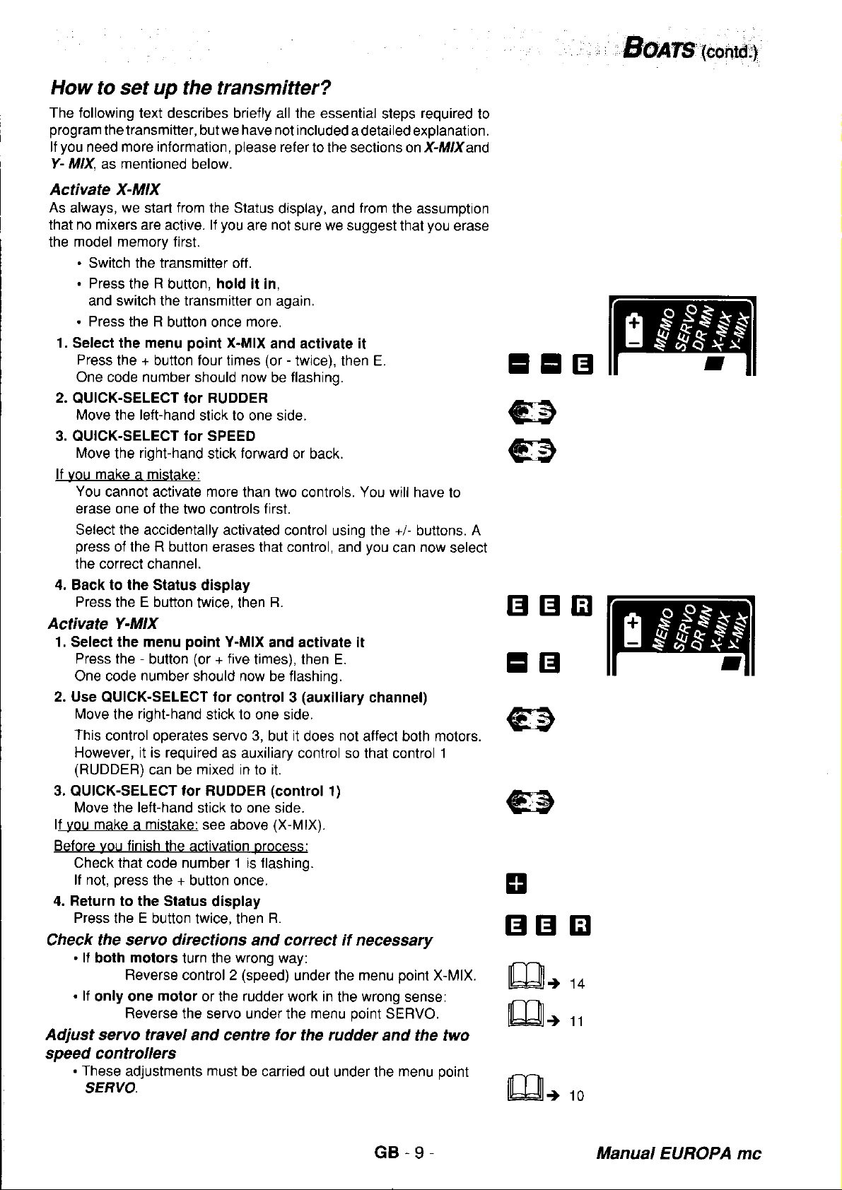
1. Select the menu
Press
One code number
2.
QUICK-SELECT
Move
3. QUICK-SELECT tor SPEED
Move
lf vou make a mistake:
You
erase one
Select the accidentally activated
press
the correct channel.
4. Back to the Status
Press the E button
Activate Y-MIX
1. Select the menu
Press the
One code
2. Use
lvlove
This
However, it is required
(RUDDEB)
3.
QUICK-SELECT
Move
lf vou
Before
Check that code number 1 is flashing.
lf not.
4. Return to the Status
Press
Check the servo directions and correct if necessary
.
.
Adjust servo travel
speed controllers
.
we
Switch the transmitter off
Press
the R button,
and switch the transmitter
Press the R
the + button four times
the
the
cannot activale more
of the R button
QUICK-SELECT
the
control operates servo 3,
the
make a mistake: see above
you
finish the
oress the + button once.
the E button twice, then
lf
lf
These
SERVO.
motors
both
Reverse control 2
only one
Reverse
adjustments
from
start
aclive.
left-hand
right-hand
of the two controls first.
-
button
number
righthand
can be mixed in to it.
left-hand
motor
the Status
you
lf
are
hold
butlon once
point
should
for RUDDER
stick to one side.
display
twice, then
point
(or
should now be flashing.
for RUDDER
stick to one side.
activation orocess:
turn the
or the rudder work in
the servo under the
and centrc
more.
X-MlX
now
stick foMard
lhan two controls. You will have
erases that control, and
Y-MlX
five
+
for
control 3
stick to
as auxiliary conlrol
display
wrong
(speed)
must
be carried out
display, and
not
sure we suggest
it in,
on again.
and activate it
-
(or
twice), then E.
flashing.
be
or back.
control using the +/- buttons. A
B.
and activate it
times), then E.
(auxiliary
one side.
it
but
does
(control
(X-MlX).
R.
way:
under the menu
menu
lor
the rudder
from
the assumption
that
you
can
channel)
not
alfect both motors.
so that control
1)
poinl
wrong
the
point
SERVO.
and the two
under the
menu
sense:
required
you
now
X-MIX.
to
erase
to
select
1
point
EEB
€
€
BBtr
EB
E
BB
ffir
Eß,
flIT}
lhf:Jlt
14
'II
10
GB-9-
Manual
EUROPA mc
Page 10
SEFyOS
(travels,
centre,
direction)
you
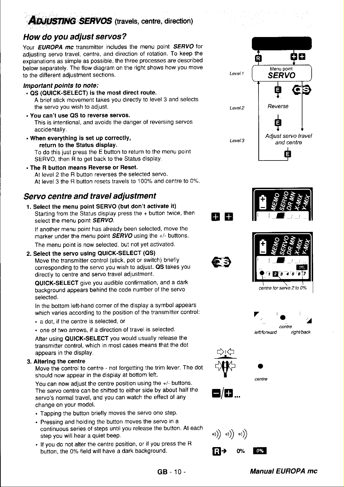
How do
Your ELIROPA
adjusting
explanations
below
to the different
Important
.
OS
.
You can't use QS
.
When everything
.
The R button
Servo
1.
2. Select the
3.
servo travel,
separately.
(OUICK-SELECT) is the
A brief stick
servo
the
This is intentional, and
accidentally.
return to the Status
To do this
SERVO,
level 2 the R button
At
At level 3 the R button
centre
Select
Altering the centre
the
Starting
select the
lf another
marker
The menu
Move the
corresponding
directly
QUICK-SELECT
background
selected.
In the bottom
varies according to
which
.
a dot,
.
one of two
After using QUICK-SELECT
transmitter
appears
Move the
should
You can
The servo
servo's
change
.
Tapping the button
.
Pressing
continuous
step
.
you
lf
button, the
adjust
mc transmitter
cenlre, and
as simple
adjustment
points
you
just
then
as
The flow diagram on the
note:
to
movement
wish to adjust
to reverse servos.
is set up correctly,
press
the E button
get
R to
means
Fleverse or
and travel
menu
from
menu
menu
under the
point
servo using QUICK-SELECT
transmitler
to centre
if the centre
in the display.
control to
now appear
now adjust
normal travel,
on
you
do
point
Status display
the
ooint
point
menu
now
is
control
to the servo
and servo
give
appears
left-hand corner of
arrows,
control,
centre can
your
and
series of
will hear a
not
0% field
behind
is selected,
it a direction
which in
centre
in the display
the centre
model.
holding the button
the centre
alter
servos?
includes the
direction of
possible,
sections.
takes
avoids the danger
display.
back to the
reverses the selected
resets
the three
most direct
you
directly
to
Reset,
travels
menu
processes
right shows
route.
to
of
return to the
Status display.
100% and centre to
to
adiustment
(but
SERVO
SEBYO.
has already been
point
SEBVO
selected,
(stick,
you
travel adjustment.
you
audible
the code
position
the
you
most cases
-
not torgeüing
be shifted to
you
and
briefly
moves the
steps until
quiet
beep.
will have a dark
don't
press
but
wish to adjust. QS
confirmation,
the display
or
ol travel
would usually
at bottom
position
either side
can
moves the
you
position,
+ button twice,
the
selected,
using the
yet
not
(OS)
pot
or switch)
number of
of the transmitter
is selected.
means that the
the lrim
using the
walch the ellect
servo one step.
release the button.
if
or
background.
point
SERVO
rotation.
level
reversing servos
servo.
activate
activated.
a symbol appears
ieft.
you
To keep the
are described
how
3 and
menu
it)
move the
+/- buttons.
ly
brief
takes
a dark
and
the servo
release the
lever. The dot
+/- buttons.
by about
of any
in
servo
a
press
you
move
selects
point
0%.
then
you
control:
dot
half the
At each
R
the
lol
Level 1
Level2
Level3
EI
EI
+€ft
I
E/8...
o) o)
@;
o)
vh
Reverse
Adjust sevo
centre
a
.',
lett/fowad
o
cenlrc
@t
B
+
and cenl
for
servo
.
cente
2 to 0"/o
-
ight/back
GB-10-
Manual
EUROPA
mc
Page 11

4. Altering
We
previous
Move the
to adjust servo travel,
appears in the
selected for
You can now
reduces
0'k lo 110Y".
.
Tapping
.
Pressing
movement (at
.0%
.
Loud
reached
.
You
CAUTION:
you
It
In
press
5. Select a difterent
You
lets
the
6. End
Press
seruo travel
assume that
page).
travel, + increases it.
has
a dark
beeps when
can reset
set servo travel
this case
R
to reset
can swilch
you
set up all the
menu
the adiustment
the E
lf not,
transmitter control
display shows which
changing.
set the travel
the button results in
and holding
each step
background if servo
maximum
travel to 100%
you
should increase
travel to 100%.
to a different
level.
button first, then R.
you
are already at level
carry
out steps
to the end-point for which
hold
and
the button
pressing
travel
to 0%;", the
servo and
servos one after
process,
it there. The
using the +/-
The
a single
you
will hear
the +
(1
10%).
by
adjust
servo using
return
(see
3
1.
and 2.
side of servo
buttons.
possible
servo step.
produces
a
travel is reduced
button
pressing
travel using
indicate
servo will not move!
it
QUICK-SELECT. This
another, without leaving
to the Status
flow diagram
anow which now
travel
The
range
of values
a continuous
quiet
beep).
that
the R button.
the + button,
you
want
you
-
button
to zero.
you
have
or
display
on
have
is
s
v
E/8...
oD
''))
t)
@+
Ettr
r)
roo"z"
7
letLtorwad
/
ight/back
Reversing
1. Select
Starting
pressing
The
code number
you
can
means
.
Number
.
Number with
2. Reverse
Every time
the servo is reversed,
changes. You
3. Select another
You can
means
the menu level.
The
code
background when
4. Move on
you
lf
alter servo
ooint
lf
the servo travels
immediately
Return
5.
Press
servos
menu
the
from
the
the +
button twice,
reverse
that
this servo has
with
clear background:
dark background:
servo
you press
can see the effects
use
QUICK-SELECT to switch to
you
that
number
to travel adiustment
press
the E
travels
2).
with
to the Status
the E button first,
point
SERVO and activate reversing
Status display, move
E.
then
of the selected
it. A code number
already been reversed.
the R
and
the
servo and
can reverse
of a reversed
you
button
(described
are to stay as they
point
reverse
switch to
you
5.
display
then R.
servo
direction of rotation normal
direction
button, the direction
rhythm
by
all the
servo retains its
a diiferent servo.
will reach
in
the
level 2 (Reversing)
to
must
be flashing
with
a dark background
rotation
of
of
of
flashing
the
watching
it
servos
level 3, where
previous
are,
your
another servo. This
in
turn without leaving
dark
section, starting
you
can
before
reverseo
rotation
model.
continue
ol
marker
you
can
by
at
EEIB
B
fll-nlr
rhhltt
EI
10
EI
1=rcvetsed
=
4
selected
GB-11-
Manual
EUROPA
mc
Page 12

function
The
Dual Rates
The
with
servo
control
respond
tive
The
is switched
optional,
two
surface
qurckly
control,
EUROPA
on and off separately
and
"now
function
different travels,
travels are
and
which can
mc is
have to be
(DR
required
powerfully.
help to
preDared
fitted
more,
for
for Dual Rates on
now less"
short)
and switch
Reduced travels
produce
for
the user.
by
makes it
between
whenever the
smoother
channel.
each
possible
them at
model is
give you
manoeuvres
channels 1 and
The DR switches
set up a
to
will Large
required to
more sensi-
2. DR
are
lnstalling
Please use
below:
Order
Order
'|,
open
Remove the charge
lalches.
2. Cut away
You can use any
display.
Install the
3.
4.
connect
The sticker
are
.
Channel
.
Channel
Check
transmitter
lf
the
preference)
5. Close
and connecting
either of the
No. 7 5742
No. 7 5743
the transmitter
the
switch or switches
the
plugged
1
2
that the
switch operates
transmitter
the
Dual
MULTIPLEX
(short
(long
toggle).
case
socket cap betore
film
switches
inside the transmitler
in.
-
connector
-
connector
plug
circuit board.
simply
the switch
over
of the eight
8
9
engages
in
the
turn the
case.
two-position
toggle)
(see
illustration).
switch
and
shows
on all three
wrong direction
plug
through 1 80
Rates switches
switches
you
remove the two
position
wells on either side
tighten the
you
where the
contacl
(it
is a matter of
degrees.
listed
wish to use'
securing
DR
switches
pins
on the
of the
nut.
Remove
latches
transminer
Cut outtiln
Fig.9:
Prcpareopening
for switches
Fig.10:
Connecting
DR switches
TGnsmitterelect@nics
ill
l(t"1".1,,
-
DR channel2
Setting
"normal"
The
where
first, so that
When
travel applies
Normal travel:
DR travel
DR
To set
1. Select the
Press the
but
2. Select
Move the
(channels
servo
You cannot
buttons.
Move DR switch
3.
you
Dual Rates
control surface
you
can
your
you
adjust
to
travel
DR travel
yet
nol
the
travel adjustment.
is
DR
only
then set
can
travels
is set up
travel
adjust both
servos
servo travel
both sides
left 40 degrees,
reduction set to
left 20 degrees,
we will start
menu
+ button three
activated.
DR
channel
stick corresponding
1
2 only). QUICK-SELECT
or
move to this
active
sides separately.
work correctly
under the
of neutral equally.
right 30 degrees
half:
right 15 degrees
from the Status
point
to the ON
when both arrows
the
MN, but do
DR
The menu
times.
QUICK-SELECT
using
to
adjustment
Position
reduced travel using
menu
in the
Make these adjustments
normal circumstances.
under
point
menu
Example:
display again.
not activate
point
the channel
tacility using
appear
you
leads
in the display,
the
point
SEflyO'
MN, the altered
DR
it
is now selected'
wish to adjust
you
directly
the +/-
+/-
buttons.
to
and
t10
EEIE
s a s a
llz
or
rl@t a s a
7
,/
DR is ON
z
z
G8.12
Manual EUBOPA
mc
Page 13

4.
Setting travel
Hold
the stick at one end-point. Adjust the travel using
buttons, and watch the effect on
Resetting
5.
Pressing
may be necessary, for example, it
switch as a
Return to
6.
Press
the E button
with
100o/.
to
the R button
normal
the operating display
+/-
the
(if
required)
resets
switched channel.
first.
then R.
buttons
the
your
model.
the reduced travel to 100%. This
you
decide to use the DR
+/-
E/8...
@r
roo.u"
Btr
Using channels I and I as
you
lf
have
connected switches to channels
always work as DR switches for channels 1
This
effect can be eliminated by setting DR
ways
two
a. Erase the model memory
Caution:
this
Brief instructions:
'I
.
2. Hold button R
3.
b. Set
You
DR travel.
adjustments separately
Briet instructions:
As
1.
2.
A
Check servo travel
Repeat
of doing this.
you
if
do this, allother settings which
model memory
Switch off the transmitter.
The
code
Press the R
DR
travel for channels 1
can only do this if
ll
we
usual,
Select the
Select channel 1 or 2 using
Move
the appropriate DR switch to the DR ON
You
should see both arrows
Press the R button to set travel
points
will also be
pressed
number
you
start
menu
of the active model memory
button once
you
have
fifted two DR
for
from
the Status display.
point
lor
2 to 4 lot the second
erased.
in,
and switch on the transmitter.
more.
have selected
both switches.
DR MN, but do not
both switch
QUICK-SELECT.
switched channels
and/or channel 2 to
lhe
switches,
in
the display.
100%.
to
positions.
channel.
8 and/or 9, these switches
2.
and
travel to
you
menu
100%. There
programmed
have
should
point
you
must make
activate
it.
position.
now flash.
100%
for
adlusting
are
for
the
t14
,.,ifötili[
EI
GNx...,
B
EE
€
@r
rooz.
7
.a
DR is
ON
Return
5.
Press button E first,
to the Status display
then
R.
GB-13
trB
Manual EUROPA
mc
Page 14

Model
What
you
lf
store
you
Caution!
Activating
reason
inputs
to
memories
information
own a
settings
the
for a
make
.
Centre,
.
x-MlX and
.
Rate
Dual
lf
the
for this
5 and 6, as
(MEMO)
can
1005,
EIIBOPA
particular
travels
(DR)
you
are
MULTlnaut system
is that
mc
for three
Y-,Ut X
difterent
model are stored.
direction
and
mixer settings
settings
using
they are
MULTlnauf!
no normal transmitter
or:
your
1020 ot nautic,
models
rotation for servos
of
affects
reserved
tor
transmitter
All the adjustments
In
detail
the entire
controls can
MulTlnaulcontrol
store?
the transmitter
these
1
lransmitter.
be connected
can
which
are:
to 6
The
modules.
Selecting
As standard
background
memory
display):
1. Select
Press the
The code
2. Select the
Select
activate,
3. Switch
Press
The
The code
background.
The Status
Erasing
you
lf
complete
memory.
What actually
to the
defaults
.
.
.
.
exception:
Sole
this
then
memory
when
you
should
the
the code
using the
memories,
the E button.
memory switch
model
want to
has of things
However,
memory.
are as
Centre
Travels
Rate
Dual
mixers OFF.
All
setting
model
menu
+ button,
number of
model memory
number
display
memories
is
1
always
you
switch
follow this
point
then
the active
number of the
+/- buttons.
return to
is carried
of the
reapPears.
memories
store lhe
happens
Everything that
lollows:
tor all servos
for all
(DR)
if
is retained.
settings
while testing
this does
is that the
to 07"
servos to
travels
you
have activated
active
you
lf
on).
procedure
MEMO and
E.
new
for a new
not mean that
factory
you
100%
100%
to
activate
memory
memory
the Status
out.
memory now
-
you
have changed
MULTlnaut
(code
number
want to
(starting
it
(1
to 3)
which
display
has a dark
model - or
erase the
can
memory
the
(default) settings
t has a dark
select a
trom the
flashes.
you
want to
you
if
currently
is left
are
is
oveMritten.
for channel
different
Status
make a
active
"empty"
reslored
The
5 or 6,
ETB
E/8...
rlz
-
E.r,s J,5
/l\
Memory 1 active
'6 ,'
is it done?
How
To be on
memory
the
1. Switch
Press the
2.
then
The code
However,
Press the
3.
lf at this
switch
are
stage
the
left
unchanged.
the safe
switch
side, check
which is currently
transmitter
the
R button
the transmitter
number of the
nothing has been
R button
you
decideyou
transmitter
oFF
one
OFF.
hold
and
active
once
do
again.
last time
active.
it in,
ON again.
memory
erased
more to
not
yet!
erase
want to erase
The contents
you
that
should
the data.
really
now be
memory, simply
the
current
of the
GB-14-
want to erase
flashing.
memory
::i.Ef,il
tr
lreElr,'l
tr
rlz
-EF'r
/l\
Eese memoty
Manual
j,z
3,s
1?
EUROPA
mc
Page 15

"two
X-,!tXfunction
The
passes
and
in both directions,
The
diagram
controls
X-MIXis atrcely assignable
mixed.
be
For each of the two controls
servo
One transmitter
rotation, the other
which the controls
the
1
and
response.
mixes
resultant signal to two
hence the letm
on the
2 arc mixed and
The range
control
moves
work
right
moves
can
shows
lhem
in,
the
mixer, i.e. any two transmitter
separately
of
also be
out"
two
signals
values is 0% to
in opposite direclions.
from
two transmitter
servos.
x-MlX.
x-Mlx wotks. The signals
how
passed
bolh servos
to
you
reversed, naturally.
The
signals
servos
can set lhe
'1
and
100%.
in the same direction ol
controls
are mixed
from
2.
controls can
magnitude of the
The
direction
in
Since the
reversed,
How do
This type of
in model aircraft are described
diagrams.
The
mixer
V-tail
A typical application
signals
two seoarate
A V-tail system
DELTA
In deltas and
mixed and oassed
When an
directions
When an
direction
X-[t Xfeature can be assigned to
it
can be used
you
mixer is very versatile. The two
BOATS section describes a
in
a twin-engined
for RUDDER and
servos.
is
described
(flying
AILERON command
(one
ELEVATOR command
(both
wing model aircraft)
flying
up, the other down).
up or
lor a very
X-MIX?
use
boat to
fo( X-MIX
wings
on to two servos.
both down).
reinforce
ELEVATOR have to be
in detail
the signals
is
further example,
is
is
any channels, adjusted and
wide variety
brieflv below. and
the
controlling
later
for AILEBON and
given,
the elevons
given,
the elevons
of applications.
most
common
namely
elfect of the
a V{ail.
mixed
as an example
applications
illustrated in the
the use of
rudder
ln
this case the
and
for X-MIX.
ELEVATOR are
move in
move in
the
system.
passed
the
to
opposite
same
Fig l1:
x'mi\er
IEEI,
,
417
How do
you
select
the transmitter
ff the mixer
a.)
you
lf
have
have erased
controls
(signals)
After
chance
working.
b.)
ln this case
your
lf
set.
for
are
you
have selected the controls,
to set the
fi X-MIX
.
select one or both
.
alter the
transmitter
For this
has not
not
used
memory,
that
mixer. The mixer
the
mixed,
you
reason we will deal lirst
both at
magnitude of the mixer
has
already
can either
input
and
is brand-new there
controls
yet
X-,lt X
in
you
100%, and
been activated:
transmitter controls
direction
for X-MIX?
been activated:
the currently active
must first select the two lransmitter
is
then activated,
for
one
will
with
model
and the two
passed
the transmitter
inputs
anew, or
(or
both)
generally
case a.).
the two servos.
on to
gives you
their direction ol
and
controls.
no
be
GB-15-
memory,
inputs
mixers
active
or
the
Manual EUROPA mc
Page 16

Activating
a.)
Starting
1. Select
2. Select
3.
4. Adiust the
5,
6.
7.
b.) Selecting
the
You cannot
select
point,
Press the - button
Button E then
numbers
Select
you
that
The flashing
flashing
the
Move on
Press the E button.
Two arrows appear
now being
control
the dark
Press the
transmitter
mooet.
Using
lf both control
direction,
servos.
lf only one
menu
Changing
Switch
transmitter
(point
You can switch
SELECT
End the
Press the
point
mixer
new control.
a
1. Select
Press the
2.
Select
Use QUICK-SELECT
be erased.
this control.
Press the
input
3. Select
Use
lf two
moved
OUICK-SELECT
Move on to adiusting
4,
Continue
X-MIX
as ever,
menu
the
activates
the dark
the controls
the two transmitter
want to
marker
rhythm changes.
to adlusting
adjusted,
which the adjustment
background.
input
-
button to
control
the R button
press
servo
point
SERVO
to the
second
to the
control
4.) and
you
if
process,
E button,
X-Mlxlo the
difterent
is already
activate
menu
the
-
button
transmitter
the
The flashing
R button.
is
erased.
new control
a
OUICK-SELECT
controls are
to and
under
as
for the
is the Status
point
twice,
square should
with QUICK-SELECT
mix, and
jumps
in
which affects
with +/-
reduce the
to check the
to
surfaces
R button to
the
works
and
second
briefly.
reverse
back
wish to.
return to the
then
Status
progrcmmed
more than
you
point
twice
The flashing
activated,
fro between
(or
the
point
tirst time,
display.
X-MIX and
E.
then
menu
the
controls
move them brietly
to the associated
That's all
and/or
the
reverse the
mixer
it il necessary
to the
transmitter
should
control
to
again.
and/or
reversing
display to
applies
effect of
your
on
reverse the
in reverse, then
reverse this
mixer
inpul by
Now set the
first control again
R,
move back
to
display.
lwo controls
tirst erase
x-MlX and activate
(or
+ four times),
and
select the
maker
will
the
these two
+^ buttons).
reversing
in
3.
the
it
and setting
activate
point.
now be
(sticks,
indicate that
both sides
to
input, + to
input
model
input using QUICK-SELECT
moving the corresponding
(point
Status
controls
erase the
transmitter
jump
rhythm
flashing
previous
it
Under
there
is
move
servo only.
travel
display
the unwanted
code
one of the
flashing
adjustors'
one after the
code
is
to
the mixer
of servo
code
the
increase
the changes
in
the
inputs
you
should
for this
5.).
with
through
lor X-MIX
tor X-MIX
it
E.
then
input
control
the code
to
changes,
marker can
numbers.
mixer inputs
the
section.
up
code
switches)
other.
number
it
inputs
mixer input
a
travel.
number with
il. Move the
on the
wrong
for
both
move to
input
QUICK-
menu
the
when
you
lf
want to
one
which
number of
and the
only be
using
and
is
The
the
is to
mixer
EEEI
E/8...
nfnr
lLult
11
s
Gttr
EEB
ۊ
tr
@
GB-16-
Manual
EUBOPA
mc
Page 17

Is
there a short-cut
reverse one mixer input?
or
You can use OUICK-SELECTto by-pass the selection of the
control
and move directly
1.
Select the
Press the - bufton
2.
Select the transmitter control using
Then move
The
arrows
.
Use the +/- buttons to reverse
.
Press the R button
Move
3. Return lo the Status display
Press
number for
code
will
control
the
the E button, then
point
menu
twice
briefly the conüol whose input
appear
in
and
you
iI
to setting up
X-MIX
(or
the selected control will flash, and
the display.
reverse
to
watch
R.
only
but do not activate it
+ four
the
the
the effects on the model.
want
/ reversing
times).
QUICK-SELECT
mixer input.
input.
to change
a control.
you
want
to adjust.
Example: V-tail
In the following example
.
.
The V-tail must
be connected to sockets 1 and 2
(standard position).
1 for RUDDER
Stick
2 for ELEVATOR,
StiCK
then be operated by servos
the transmitter
and
will
be set up as follows:
'1
and 2. Sticks 1 and 2
on lhe transmitter circuit board
transmitter
EE
the two
BEI
should
give
you
lf
model
fuselage centre or away from the fuselage, i.e.
lf a RUDDER command is
should deflect
Activate X-MIX
As always, we start from the Status
MIX is not
memory.
.
.
.
1. Sefect the
Press the - button twice
A
2.
QUICK-SELECT
Move the
3. OUICK-SELECT
Move the
4. Move on to adiusting / reversing the inputs
Press
You can now adjust lhe mixer input using
lf both control
mixer inputs
incorrectly,
corresponding servo only.
You can switch between
using QUICK-SELECT.
5. Return to the Status display
Press
an ELEVATOR command, the
should deflect
already activated.
Switch off the transmitter
Press
the R button,
and switch the transmitter on
Press R
number
code
left-hand
right-hand
the E button.
the E button, then
in
opposite directions
given,
in
the same direction
and set up the
lf
hold it in,
more
once
menu
point
X-MIX and activate it
(or
+ four times), then E.
should
surfaces
using the R button.
return
now
for RUDDER
stick to one side.
lor ELEVATOR
stick foMard or back.
move in
to the menu
the two
B.
the two control surfaces on the
you
be
two control surfaces on the
(both
(both
surlaces left or right).
mixer
display, and the assumption that
not
are
aqain
flashing.
the
lf
only one surface works
point
mixer inouts
sure, erase the model
the
wrong
SERVO and reverse the
surfaces towards the
both up, both down).
model
X-
+/-
buttons.
direction,
reverse
the
Fig.12:
V tail
EE
@
€
tr
E/E
Eß,
trEt
11
rlz
7Eo
/l\
45 67
GB-17-
Manual EUROPA mc
Page 18

function:
The
Y-MlX
The
in contrast
servo
mosl common
This mixer
installed.
is
(see
module cannot
lf this
transmitter.
In
this
in flight.
off
mixer mixes the
to the
In other
only.
aoolication
can be switched
This switch
diagram
mixer
.
no
.
a
.
MULTlnaut
case
inside the transmitter).
be connected
is activated
if:
switch
MULTlnaut
the
X-MlX
is
is activaled.
mixer
Combi-Switch
only be
and
you
when necessary).
pilot.
you
install the
switch
switches.
the
il
the
turns can
ailerons
Smooth
function allows
separately,
experienced
How do
The Y-mixer
Dual Rates
the
as
sockets
transmitter
marked COMBI-SWITCH
shows
IMPORTANT:
"Master"
By
which
parallel
in
Example:
AILERON stick
The
AILERON
ln this
socket
lo
You can tell
number
Select
1. Select
Press the
lf
dark backgrounds.
Move the
2,
(new) Master.
Use the
Press the
3.
Now onlv
The two arrows
reverse the
with the
4. End
Press the
we mean the transmitter
controlstwo
with
is controlled
case the
1,
which appears
the
the
mixer is already
the
channels
its
own).
AILERON
the
and
which
Master
menu
-
button
tlashing
+/- buttons.
E button
the code
travel
keys. Press the
+f
process,
the
E button
"Make
words: a second
connected,
control
can
rudder are
to
one out
inputs ot
function, the
for this
is
connected
then
still be used,
llown by a
control both
is the combi-switch
and OFF
ON
at the
it is
switched
or
module
moved simultaneously.
This
of two"
two transmitter
product
mixer
input is mixed
in flight
the socket
to
Note that a
same time.
on
is
connected,
but cannot
model - as by
controls
particularly
is
Y-MIX switch?
(combi-switch) is installed
The switch
position.
who
of
(starting
is the
(in
otherwords,
is to be
RUDDEB control
Master, and
by channel
control
the two
when
point
once
The llashing code
marker under
in the transmitter
controls
you
from the
y-MrX
(or
+ five times),
activated,
number ot
in
display
the
for
return
the slave
the
R button
to the Status
first, then
is connected
M-NAUT.
/
"Master"?
control
operates a
RUDDER
1, RUDDER by
to socket
is Master
activate
and
the Master
indicate that
R.
the
Status display):
activate
two code
number is the
the code
channel.
to reverse
display'
conlrols.
is
in with a signal.
if
an
marked Combi-Sw.
MULTlnaut
automatically
or
be switched
a full-sized
by one stick
useful
in exactly
to one of
The sticker
(stick,
is to
channel
should
3.
by the
mixer.
it
E.
then
numbers
number
has a dark
you
can
Make adjustments
However,
passed
(see
below).
auxiliary switch
The
(but
for
the
the same
inside the
or switch)
slider
second channel
tollow
3.
be connected
flashing code
have
will
Master.
tor the
background
now adlusl
to one
The
control
your
by
on and
aircraft
Y-MlX
also
less
way
the two
(slave).
or
Switch
(Conbi-Swltch)
Fig.13:
with
switch
)12
Fig.14:
Connecting
the conbi
switch
EB
E/E1...
El
BEI
COMBI-SWITCH/M.NAUT
elect
rcn
I
ics
iltl
itter
Transm
rlz
E,Al
=
MASTER
2
,l\
45 67
GB-18
Manual
EUROPA
mc
Page 19

How do
a. Activate
Requirement: Y-MIX must not
1. Sefect
Press
The menu
under one ol
2.
Select the transmitter controls using QUICK-SELECT
CAUTION: be sure to move the
(see
Locate
you
flashing marker
the
lf
mixer operates as a combi-switch.
Move
3.
the
Press the E button.
Both
that travel
Move the control to one
you
Y-MIX with
Y-MIX
the - button, then
point
the code
previous page)
the two transmitter controls
wish
flashing
you
Master
arrows appear at bottom
mix,
to
rhythm changes.
select the
on to adlusting and/or
for
Y-MIX?
use
QUICK-SELECT
point
menu
E.
is
activated and the
numbers 1
move
then
jumps
to the corresponding code
RUDDER
both sides
end-ooinl and
already be active!
and activate it
flashing
7.
to
Slave
(sticks, pots,
them briefly one after
and AILERON sticks, the
reversing
left in
the display.
is
to be adjusted simultaneously.
marker appears
lirst.
then the
mixer
the
hold it
there.
switches) which
the other.
numbers
This indicates
Masterl
and
y-tt
X
input tor
EB
The
Now use the +/- buttons to adjust the mixer input,
effecl on vour model.
Tapping
Pressing
of steps until
will hear
you
lf
background. At 200% every step is accompanied
beeo.
You
4. End
Press
b.) Selecting different trunsmitter controls
mixer
You cannot activate
select a new control,
is
1. Select lhe menu
Press
2.
Select the transmitter control and erase
Use OUICK-SELECT to select the control
The flashing marker
Now
control
3. Select the
Use
When two controls are active, the
switched between the two code
(or
the +/- buttons).
4. Move on to adiusting and/or reversing the mixer inputs.
Continue as under
the button
and holding the button
quiet
a
set the travel lo
reverse
can
process,
the
the E button once, then
already
the - button once
press
the R button. The flashing rhythm changes, and the
is erased.
new
QUICK-SELECT
produces
you
release the button again. At every step
beep.
zero,
input with
the
return
prcgrammed
more
than two controls
you
should lirst erase the unwanted one.
point
Y-MIX
(or
jumps
control
again.
point
3. in the
a single step of servo movemenl.
produces
the 07o
the R button
to the Status display
R.
and activate
+ five times), then E.
to the code
flashing marker
numbers.
previous
a continuous
marker will have
for Y-MIX, if
for Y-MlX.
it
it
which is
number for
usino QUICK-SELECT
section.
watch
and
a dark
a loud
by
il necessary.
you
lf
to be erased.
this control.
can only be
the
series
you
the
want to
E/8...
',)
"')
o)
0./.:
@,
?00"/"
.D)
,
EI
trI
EB
@
tr
€
GB-19- Manual EUROPA mc
Page 20

We developed
who soeciälises
were:
.
small
.
as
.
as
We believe
the
in
size,
functions
many
little exlra
we have
MULTlnaut
multiJunction
compact
complication
met our
lop system
shape
as
Possible
goals.
working
specifically
models
the electronics
to
for the
possible'
as
design
Our basic
modeller
aims
Safety
Please
notes
to observe
sure
be
.
Do not exceed
.
Connect
cable
this
(at
.
lnstall
current
.
Do not
material.
the common
supplied
cable,
0.25
least
the
warning
wrap
The unit
receiver
make
the
Specifications
Operating
Current
outputs
Operating
Uäximum
Nominal
Outputs
Operating
Maximum
Nominal
voltage,
consumPtlon
-
(short-circuit
F2
A1
voltage
current
current,
MOT
voltage
current
current,
for the
per
continuous
1 and
per
continuous
tollowino
the
stated
the
(black, AMP-plug).
sure
mm).
sq
module
light
receiver
must
receiver
load
MOT
motors
of
motor
currents
negative
is ot adequate
it
in such
(red
LED)
module
have adequate
module
protected)
load
operation
(short-circuit
2
operation
Doints:
voltages'
and
terminal
you
lf
cross-section
way that
a
visible'
is
foam or
in
air
4 NC cells
approx.
5 - 24
approx
approx
protected)
6 - 12
approx
approx
(earth)
have to
using
the
similar
circulation'
mA
20
v
mA
800
mA
550
V
A
l 0
700 mA
the
lengthen
excess
hotl ci
S
tcuit i nd
icator
What
with
...
.
.
.
.
...
naitic
Once
modulä
now oroceed
is the
the
you
have
the
Bead
Please
transmitter
MULTlnaut
you
check
lnformation:
lnstall
lnformation:
Connect
Examples:
Truck
Boat
Switched
Soeed
you
.
.
.
read
do so.
the
the
the auxiliary
(end-point switches)
controllers
wish to
with a
lnstall
Calibrate
Connect
you
have
is safely
best
system,
EUROPA
a
instructions,
right through
with
Top iystem).
transmitter
MULTlnaut
f unctions
way ot
if ...
mc
charge
great
care,
programmlng.
Top receiver
working systems
(relays)
(motor
expand
a
MllLTlnaut
the transmitter
transmitter
the
the control
carried
installed
described
as
module
out
your
in
above
getting
nautic
the
the
as
You
suppression\
EaIROPA
Top control
module
procedure outlined
the
transmitter
set?
batteries'
instructions
main
well as lhese
recharge
can
in the
(electrical
mc
and
(for
EUROPA
the
started
for
instructions
batteries
the
21
Page
model
21
Page
loads).
22
Page
23
Page
22
Page
22
Page
1005,
module?
24
Page
24
Page
25
Page
above'
readyto
is
mc
GB-20
your
1010'
use
nautic\
(for
the
while
1020
nautlc
the
Youcan
'
ol
att electical
15: OveNiew
Fig.
units
MOT 1 and
receiver
of
Manual
MOT
module
EUROPA
2
mc
Page 21

What
Before
transmitter
a EUROPA
MULTlnaul
(receiver
has
you
can use
which
mc nautic
module
output 5).
to
be done at
MULTlnaut
the
channelthe module
lhe module
in
model
the
the transmitter?
top system
is
connected to. lf
is
connected to
must
also
you
have
channel
be connected
,lell"
to
your
system
i.e.
5,
to channel
the
is
the
5
Starting from
1.
Select
Press
One of
background.
flashing)
switched
2.
Select
Use the +/MULTlnaut
Only
Channel 7 is
3. Switch MULTlnaut
Press
this the flashing
cnange.
Longer
ON for the
flashing
channel with MULTlnaut
background.
4. End
Press
the Status
the menu
the +
the code numbers
black
ON for
MULTlnaut
the
channels
the R button
ON
code number
cursor
process,
the E
point
button
you
lf
background,
that channel.
buttons to
control unit is
5 or 6 may
reserved
rhythm
(dark)
than
to a different
return
button first,
display,
lhree times,
see one
on or oft
to reverse
to Status
this
DR MN
5,
6 or 7 should now
code number
this means
channel
select the
connected.
be used for
tor later
of
OFF means
then R.
expansion.
the
the selected
you
have
code number
now
switched
display
procedure:
is
the
and
activate it
then E.
have
with
a solid
that MULTlnaut
channel to which
the MULTlnaut
channel's
that MULTlnaut
selected. lf
state. When
code number
you
with +
ON will have
a dark
(non-
is
the
system.
will
is
switcheo
move
-,
or
the
a solid oarK
vou oo
the
EBEIE
E/8...
Receiverinthe
model,
connectedto
channelS
Btr
How is
installed
The control module
be on the
MULTlrraut
you
connected
modules
The receiver
tape
How
MULTInaut
Before
consider carefully how
switches
pots
and
enter
reminder
täe MULTlnaut
in
the model?
in
the transmitter
same channel. This
receiver
are using a EUROPA
to channel 5
you
must
module
(servo
do
tape)
you
module must
use
can be fixed in
or self-adhesive
connect
Top
you
install
pots.
and
with
reference
your
own arrangement
when
MULTlnaut
the
Fig. 17
completing
top receiver
means
be
mc nautic,
as standard. lf
channels
5 and 6.
the model
Velcro.
the
system?
lop system in
you
wish
to assign
(right)
shows the
to
receiver
the
in
this diagram,
the wiring.
module
and the MULTlnaul
that the
connected
since the control
you
wish
the working
assignment
outputs. We
plug
servo
to use two MULTlnauf
using
your
and use it later
attached
receiver
to
double-sided foam
model
systems
of the switches
suggest
receiver
must
to the
socket 5 il
module is
you
should
to the
that
as a
you
Fig. 16:
Connecting
module
to
(example:
the rcceivet in
theMULflnaut
channel5)
model
the
MOT
rcceiver
GB-21
Fig. 1 7 : Assignnent
receiver
outputs A
to F and MOT l/2
Manual
ofl\,lULTlnaut
EUROPA
mc
Page 22

Example:
Many
with an electronic
model.
you
musl wire up
examole
comDleted
assignmenl
way
any
For this
leads
mooule.
truck
modeltrucks
system,
To operate
shows
below
in a Mercedes
is only a suggestion,
you
cnoose.
application
which are supplied
functions
(e.9.
WEDICO)
controlled
functions
these
a tailor-made
the connections
you
can use
with the MULTlnaut
are
control
truck cab.
and can
the
fitted as standard
by switches
via the
that
2-core connecting
on the
RC system
system.
The switch
be altered
The
have to
receiver
be
in
Receivetin
themodel
WB
terminal
Soldet
the circuit board
on
f
o
o
Ll.l
t
Fig. 18:Wiingexanple
Connecting
relays and
tooutputsA-F
Voltage
peaks
motors).
you
lf
want to
instali orotective
peaks.
adviCe at
fOr
connect
Suitable
diodes
yOUr
Suppressing
speed
the
To
avoid
motors
1O
sufficient
electronics
lf
negative
must be
(nano-Farad)
nF
motor
the
controllers
danger
the
for this
shops.
has a
terminal
C)
when
occur
such units
diodes to
are types
local eleCtronics
electric
RC interference
of
suppressed
ceramic
purpose.
metal case,
(earth).
WEDICO
truck
motors
you
switch
MULTlnautoutputs
to
shield the
'1
N 4148 and
motors
MOT 1 and
using capacitors.
capacilors
These
connecl
off
electronics
you
if
ShOp
connected
from
rated at a
items are also
the casing
(inductive
inductive
against
1 N 4001
are
loads
A
F,
to
these
(or
simila0.
UnSUre.
to
2
electric
motors, all such
minimum of
readily available
to the common
loads)
(relays,
you
must
voltage
Ask
50 V are
in
Mot
,
1
€a
$ !.1
-'n
?
19:
Fig.
Connecting
Fig. 20 : Motot suPPrc
Horn
Positive teminal
5Vto24V
protective diode
a
s s ton
GB-22
Manual
EUROPA
mc
Page 23

Example:
The range
The
example we have
rescue
example is not
typical applications
by the MULTlnauf
The
drawing on the right
systems are
keep the illustration
lew
typical applications.
Hon,dieselsound
Generally speaking
systems are connected
lect tonic
e
module.
Deckfloodlight,
positionlamps,
lighting
Take
cate
maxi mu m
wh
en con
boat functions
of working
cruiser. lt is not
intended
to demonstrate
fop
connected
easy to understand,
these two
to an
g
so u nd
syslems in
not
pe
necti
ne rato
e
to exceed
rmi
le
ssi b
ng bu lbs i n
r
general
the
cu ffe nt
paral
systems on a model
chosen
possible
could be a firejighting
to show
to be
comprehensive. Instead
boat is virtually
every
the versatility
system to
shows how
model
the
the individual
to the MULTlnaut
we have limited
k
\
le L
possible
and
fan.
boat
top
system. In
inexhaustible.
boat or
variation,
it
potential
a sea
and our
uses a few
offered
auxiliary working
an effort to
ourselves
ro a
Receiverin
connected to
channel5
the model,
Motors,
S ee th e notes
suppression.
nehys
See the noteson installing
prctective
Motor
MOT 1
The centrc
outquts must
pos
Con necti ng
lf
systems
install
operated, the end-point
system stops,
pumps
rcg ard i n g motol
diodes.
controllers
2
and
terminals ol these
ttve baft e ry te rmi na L
be connected to the
end-po i nt
you
wish
to use molor
(e.9.
rotary
end-point switches
and can then
two
controllers for
movement
switches
direction.
The
illustration
switches
for
contacts are
end-point switches
below shows how
the speed
provided
controller MOT
for MOT
are used to limit
switches :
positionable
of a crane),
limit
to
the working
close a contact. The
only be run back in
to
connect the
1. Two vacant
2. In the rlght-hand
anchor winch
5V
to
24VDC
drive
you
can
range. When
drive
the opposite
end-ooint
example the
travel.
6
to
12
V DC
pairs
Anchor winch
of
Fig.22:
Connecting end-point
switches lot MOT 1
red
sde
wotking
ange
black
stcle
GB-23-
Fig. 21 : Typical
-f
(fi
rc
ig hti ng
boat, sea - re
wiing
diagram in a modelboat
scu e cru i ser o r
Manual
i lat)
sim
EUROPA
mc
Page 24

How do
existing
an
The transmitter
can either
nautic
mc
exoand
lo
This
you
install this
transmitter,
transmitter
the
is how
you
transmitter?
control
transmitter:
sharp,
1. Using
2. Open
3.
4.
5. Carefully
To avoid
6.
7. The transmitter
a
the switch
over
the transmitter
Place the
connect
cafibrated
The larger
using
The smaller
knurled
two circuit
the
tirst.
of the
screws.
two
circuit
nuts used to
press
far as they
in as
them
you
When
detent
which
rotate the
position
you
can
interference,
connected
be
(about 4 cm
wire
the solder
joint
briel;
Switch
set all
Press the
transmitter.
is reluctant
by scraping
area
full details
üansmitter
the
sliders
trim
E button,
The code
background.
next steps
The
Trim slider
a.
Hold the
b.
Trim slider
c.
Hold
d.
stick at
the slick
secono.
you
Once
behind
Now to
You will
plug
and
Once
the code
Put the
You
have completed
the code
calibrate
need the
bridge
to
6) to the
you
have
numbers
calibration
will find the
accessories
instalt a
module
module
or
install the
pointed knife
MULTInautTop
is available
as a
in a
fit one
provide
to
control
(balsa knife) cut
apertures.
boards
modules
in
yet;
the tlansmitter
Description
tlvo circuit
board
secure
rotary
the
hvo
that
so
find without
boards
is fixed
the two
adjustor
go (lllustration right).
will
knobs they
you
have a
having
the control
the transmitter
to
place,
in
long)
to adhere
it with a
has to be
now
Page
27:
on
OFF.
and sticks
pressed
it
hold
numbers
E button
Belease
to one
the
must be
end-point
repeated
the same
opposite
to
at the
end-point
corresponding
this
number
for that
MULTlnaul
the
calibration
5 and
plug
in the
arms,
contacts
ouler
this
6 will also
away
plastic
mounting
the centre
corresponding
completed
plug
(output
under
second
unit
EUROPA
MULTlnaut
module
transmitter
the
page
on
27.
is fixed
lrom the
switches.
knobs
will
neulral
look away
to
screening
unit
electronics.
shown
as
the screening
to
screwdriver.
small
calibrated
centre.
to
in, then
1 to 6 should
again.
tor all
(left
end-point
forward)
or
for about
(right
end-point
procedure,
will disappear.
stick
system
plug (2-pin
of the
contacts
process,
disappear.
in a sate
which contains
bag
screws
module
7 5881
No.
Order
in an existing
1010 and
1005'
mc
functions'
Top
your
in
the
away
as shown.
lo be
has
inside the
outside
into
click
position
in the
This
four stick
or
lhe
plug
MULTlnaut
the
place.
with the
place,
pushing
into the centre
(motor
from the
plate
Solder the
illustration
plate,
procedure in
is
the
switch
on the
now all
planes:
1
second'
back).
for about
square
dark
lug). Use
with
channels
in turn
squares
dark
etc.)
in
You
EUROPA
1020
panel
film
Do not
transmitter
OFF)
model
must now
length of
lf
the
clean
have a dark
1
this
(5
behind
the servo
Remove
latches
Openthe
tGnsmitter
cüawavritm
Fit rotaty
Fig.23
Fig.
Fig.25:
knobs
24 :MULT
Transmittel
elecÜontcs
ooooaaa
o6aa
o66a
Fia.26:
I naut conlrcl
Eatlh connection
5
6
Position ol the
unit
(see6.)
Placethecalibration
plug
in these
Postions.
a
6
calibration
plugs
GB-24-
Manual
EUROPA
mc
Page 25

This
is how
1.
2.
lmportant:
The
also be
MULTlraut
the section
proceoure.
plug
The
should
The
two connections
function.
The red
you
fit
the
will
not
Connect
as
slandard,
receiver.
circuit
board.
channel
activated
"What
you
connect
with
the marker
be connected
wire must
plug
be assigned
the unmarked
since
In
this
remembe.
which
to
under
system
has
flfl ll
thhlt,
to one
are wired
face
the wrong
correctly.
thls socket is
case the red
to
activate
you
have
the menu
you
until
to be done
21
the
trcnsmitter
(coloured
of the hvo
in
the
outside edge
way
round
plug
to
channel
wire must
the MULTlnast
connected
point
have
carried
at the
controt
sticker
parallel,
directly
DR
transmitter?"
on the
transverse
and have
of the
the
switches
S or 6.
accessible
face
the centre
the
controi module
you
MN.
out this
modute:
plug
body)
connections.
the same
circuit
board. It
and adiustors
Channel 5 is
at the
of
svstem!
cannot
step. Turn
for
details
use
useo
lhe
musr
the
bacK
of this
lo
Fig.
27 : Ttansmttlet
controt module
conneclion
Long
The
centimetres
For this reason
3-pin connectors
items
precisely.
cables supplied
This is
1.
2.
3. Slide the
What
End-point
Transmitter
Receiver
connecting
cable lengths
in
a small
a
you
can make
you
lf
don't want
can
how
to connect
piece
Cut
a
about 4 mm
Solder the wire
a heat-gun.
lighter.
of heat-shrink
plastic
You
please
but
accessories
switch
End-point
module
systems
The EUROPA
module.
All
othet EUROPA
one
Extra receiver
transmitter with
several models
switches
and limit
(see
contrcl
or two MuLTlnaut-top
module
leads
required
length
are
supplied with
be extended
ol insulation
to the
sleeve
can also
in working
ship's boat
heat-shrink
of
up the leads
to wield
plug:
a
from
plug
over
shrink the
be very
are available?
set
are
connected
the working
also:
Connecting
module
mc
nautic
mc
modules
a
second control
ready
can
transmitters
are
run.
lo
models
to more
sleeving
theMULTlnautreceiver.
yourself
a soldering iron
using
sleeving
the wlre
terminal.
the soldered
caretull
vary
widely
lhan a metre
to suit
screw terminal
about 1
end.
joint
sleeve with
in
a suoer_lanker.
and
several 2-pin
your
and heat-gun,
blocks.
cm long. Remove
and shrink it with
a ciqarette
Order No. 7
to the MULTlnaul
range
of electric
point
end-
fitted
be
control modules.
needed
with
can be expanded
you
if
module,
positioning
switches).
Order
Order
No. 7
a second
No. 7
expand
you
or if
your
want
-
from
a few
ano
Usino rnese
appäcation
the
5885
receiver
5881
control
fitting
by
5882
keeo
to
Sttipinsulation
Soldel
Shink
@
-..
.€Ft'p
-......d
F=
rlFig.28
GB-25
Manual
EUROPA
mc
Page 26

you
lf
want to alter any
to carry out
.
Check
possible
.
Check that
ate correct:
.
Fe-calibrate the transmitter:
the
that
and
How can the
outputs
The
electronics
sockets
adjustors,
(MULTlnaut,
controls
output bearing
Example: the elevator
conlrolled
you
must
inside the transmilter.
The
table
limitations
available.
be assigned?
to which
switches,
mixers, Dual
the servo connected
the same
via receiver
connect
on the
which apply to the
connections
following
what
the directions ol servo
steps:
you
permissible:
transmitter sticks
your
ot
right
EUROPA mc transmitter
you
can connect
MULTlnaut).
number
of
output
the elevator slick
shows
inside the transmitter,
want
to do
is
see table 3
rotation
see
see
and
various conlrol elements
lf no
special
Rates)
your
the
nine receiver outputs
each
to the
model is to be
3. To achieve this
to socket 3
possibilities
functions are switched on
input
receiver
and
it is important
page
26
page
27
receiver
have a total of
(sticks,
Outp.
No.
l too
7to9 Switches
Possible control
Stick,
Switches
pos.:
2
pos.:
3
(2-pos.
nine
elements
Pot,
always
channels 5/6 only
or 3-pos.)
Servo adiustment
facilities
Centre +/-50%
Travel 0% to
Direction
No adjustment
1 10%
per
side
Are the transmitter
correctly?
plugs
The
symmetrical.
ensure that
to check
you
lf
turn
'1.
2. Move all the
3.
you
lf
...
which connect the transmitter
Thus they can
mixers in
the
that all
find
it through
Switch
centre
Press the E button,
In
the
background.
dark
To
ensure
correctly, the
arrows
.
Control
.
Control
Don't
you
lf
transmitter off again.
have to turn
you
will have to
section describes
the controls are connected
anything
180 degrees and
the transmitter
transmitter controls
(sticks,
display all the code
that the
direction of operation
in the display:
right or back: arrow
left or
press
any buttons!
check everything
your
connected
trims, adiustors,
hold it in, and switch
mixers in
forward: arrow
The stored
plugs
re-calibrate the transmitter.
how to do this.
be connected
otf,
and
5,6
TaAe 3:
controls connected
controls to the electronics
"correctly"
transmitter
inconectly, simply disconnect
plug
numbers 1 to 6 should
your
find no mistakes, simply switch
round,
work correctly,
properly.
it in again.
for channels
3-position
the transmitter
transmitter
must correspond
righVback
lefvforward
values are
...
now retained.
The
"reversed".
or
it is
1 to 6 to
switches).
now
are able to
to the
following
MULTlnaut top
(only
if active,
otherwise as outp.
possibile
intemal
are
to
essential
plug,
the
arangements
B
have
work
on.
a
reE&?
q
the
1 to 6)
v
description of
See
MULTlnaut top
7
left/forwad
./
ghLhack
GB-26-
Manual
EUROPA mc
Page 27

How
are
sticks
calibrated?
Before
the sticks,
5. End
you
carry
adjustors
1.
Switch
2.
Set
(sticks,
The
the E
Press
3.
In
background.
4.
Calibrating
The
ot each
required,
orocesses.
For
.
.
.
.
For
connected
.
.
one second.
When
in
Once
square
It
the
engaged
process.
When
numbers
backgrounds.
Press
The
oft the
all transmitter
trims,
position
button
the E
the display
calibration
stick. Thus
tot
each
Move
the
Hold
the
second.
(e.9.
lelt
Move
the
Hold
the stick
second.
and the
disappear.
Hold
When
dlsplay:
Move
dark
every
the
the end-point
lefvforward
the control
the
the display.
the
electronics
behind
dark
correclly
the calibration process
lo
process,
the
the E
calibration
stick
The
and
other
out the
which
pressed
button,
the EUBO2A
trim to
stick
At
the
/ forward).
trim
other
to
control
end-point
square
which
button.
calibration
and switches
transmitter.
controls
adjustors,
the code numbers
procedure
and
at the
end-point
to the
at
opposite
square
transmitter
channels
at one
the
code number
on the
controls
return
is
complete,
3-position
the
controls
in will
hold
for
a EUROqA
each
one end-point (e.g.
corresponding
opposite
the corresponding
arrow
behind
1
end-point
is
reached
or righvback.
to the
opposite
ls reached
have
does not
contacts,
to the
transmitter
process,
work
in
tor
channels
switches)
are in
be
stored
it in,
and
1
to 6 will
is
carrred
mc 1005
mc 1010,
direction:
an arrow
end-point.
should now
the
code number
control
to 6:
for
an arrow
end_point
the
detected
are
and
the two
will
disappear,
then repeat
is
complete,
connected
Status
the Status
it
is
essential
the
correct
1
to
you
when
as the
switch
out
1020
end-point
will
end-point
(slider,
about
opposite
disaooear.
centre
on
all have
separatelv
two
and nautic
left).
appear in
appear in
switch)
one
will
aDpear in
and hold it
arrow
end-points.
check
the calibration
none
should have
display
display
controls
to
check
sense,
for
for
should
that
ordirection.
6 to
centre
switch
the
processes
second.
on wath
oosition.
transmitter
a dark
for
each
tour
about
the
display
about
the
display,
which
the
for
will
appear
the
plug
the
ot the
dark
appears.
axrs
"re
one
one
about
oarK
code
that
is
is
lEEl,
wH
ArA
___!.
\_
-
ry
tr
re[p
,42,
s
q,
v
,u
7
left/fotuard
/
right/back
Ratchet
How
lf
automatically,
the transmitter
the
Fit
of
ratchet
is
you
want
stick axis
ratchet
the
ratchet
the
spring.
the
one
you
and remove
you
spring
varies
stick ratchet
stick function
can install
wish
to
as shown
according
to,,stay
ratchet
a
return
the
convert.
in
the
to the
installed?
put',,
i.e.
instead
spring
diagram
tightness
of
the
and
on the right.
ot
not return
return
neutratising
the screw
to neurral
spring.
The
stillness
holdino
G8.27
Open
ärm for
the
Fig.29:lnsta
ing
the
Manual
stick
rctchet
EUROPA
mc
Page 28

How
Open
First
plug
ihe;ircuit
able
charge
The
occurs
When
engages
do
the
disconnect
with the
see
to
socket.
will burn
fuse
in the
you
in the
you
change
transmitter.
the battery
red / black
charge
and
board
(and
change)
if
out
transmitter
re-position
the circuit
plastic
the
from the
lead, see
the
electronics
switch
illustration
socket
fuse
the
charge
board,
knob.
fuse?
electronics
on
its
out of
(2
fast-acting)
A,
is
current
too
when charging
or
care that
take
(disconnect the
lf
right)
the
guide
slightly,
located
high, or
if
a short-
switch toggle
the
you
you
under
battery
pull
now
will be
the
circuit
latches
Open
ttansmiftel
-
Teacher
first steps
Your
easy
and
experienced
EIIROPA
You(
changes
lf vour
shbuld
transmitters
selectively,
For all
ouoil
ieächer
crystals,
"teacher"
other
lead, Order
What's
The correlation
transmitters
other
standard
The
works on
The left-hand
elevato0
The standard
you
want
lf
need to
board,
circuit
Pupil operation'a
in the
your
on
modeller
or adjustments.
the
use
trainer
the
i.e. one by
MULTIPLEX
pupil.
and
settings,
mixer
different?
between
(def
ault)
righlhand
channel
via
have directional
to
round the
turn
then
world of
bank
for
mc can
PROFI
has a
teacher/pupil
can
No. 8 5045,
In
this
ot lhe
arrangement.
stick
stick
channel
switch
sticks
re-calibrate
radio control
account
your
first few attempts.
be used
mc or a
lead,
transfer
one.
transmitters
which
case
mode
stick
sticks
EIIROPA
intended
is
.
1
intended
is
2.
works
control
physically, swap over
great
be secure,
can
you
if
as
switches
it is necessary
and channels
on channel
the transmitter.
enlist the
"pupil"
Order
the control
etc. between
mc series.
for directional
to control
on the
transmitter
Commandel
No B
channels
you
should
power
the
is
motor speed
5.
left-hand
idea!
stressJree
assislance
without
ttc system'
. With these
5121
to the
use the
supply
match
to
two
the
not the same
Figure 31
control,
stick,
plugs
the
teacher/
betvveen
transmitter
transmitters'
shows
and
(or
then
at the
ot an
any
you
trainee
with
as
the
you
will
main
Fig.30:
Changing
thefuse
: Stick assignnent
Fig. 31
EUBOPA
nc 1 005
GB-28-
Manual
EUROPA
mc
Page 29

Swapping the
1.
Open the transmitter.
2. Undo the
The return
3. Remove the stick mechanics.
To
screwdriver, then lift
unit stays in
4. Femove
Push
section
slot.
5. Rotate the
assembly again.
Please note - importanl:
The lugs
the stick top
6. Screw the mechanics in
Check that the stick and
toul
or
two screws
do this
lhe blanking
the blanking
using a blunt
on the mechanics
on anything.
sticks
spring must not
you
should carefully
the transmitter.
plug
mechanics
stick
section.
round
retaining
be
out the mechanics. The
plug
from
out from inside from
instrument.
place
trim
each stick
removed.
press
the bearing outwards with
the
Press
through
must engage in
again.
lever move
lever
trim
the stick unit top
plug
the
g0
degrees, and tit
freely,
mechanics.
part
top
of the stick
slot.
into the
the recesses in
and do
other
not
Remove
latches
a
Open
tan6mitter
the
jam
Fig.32:
Conveiing the stick units
How are the
You will need
that the stick assignment is correct.
.
Direction control stick
(now
on the
to socket 1 , black wire
.
Power
(now
on the
to socket
How is
lf the transmitter is
mixers,
the display
the transmitter re-calibrated?
the correlation between the
must
sticks connected?
to swap over the
left
of the transmitter)
control stick
right
2,
black wire on the
work
to
be correct.
(seen
from inside
plugs
on the batterv side.
of the lransmitter)
correctly when
stick
first
So
the ttansmitte]
at the main
battery side.
movements
check this:
circuit board, to ensure
you
adjust
Lugs
servo travel and
and the arrows in
Tim
lever slot
Fig.33:
Stick unit connections
thettansmittet)
(seen
Beanng
frcm inside
Are the transmitter
Then
carry out the calibration
section:
How
are sticks and other
controls correctly
process.
procedure
The
contrcls calibrated?
connected?
is
described in the
GB-29
il-nr
lbJ3)|r
27
Manual EUROPA
mc
Page 30

Arrangement
baftery,
The sketch
components
location
building.
start
servos
below
inside the
of the
Receiver
Please bear the
receiver
the
.
.
.
.
.
.
.
in
it well away
Keep
electrical
and
Lead the
possible
Protect the
Ioam and stow
Do not alter the
Deploy the
(never
not deploy the
Do
reinforced
not
Do
fibre reinforced
screenlng).
hterterence
magneto
.
Screen
sleeve,
ignition coil.
the
.
a shielded
Use
.
receiver battery
The
ignition
the
.
Keep the
from all
receiver battery.
the
.
Keep the
ignition
generous
.
you
lf
use
minimum
10 A
ot
shows
RC equipment
tips
following
your
model.
aerial out of
route.
receiver
aerial
it
leave
model component
the end
stick
suppression
/ electronic
ignition lead
the
fix
and
system.
ignition system at
parts
leads between
battery as
cross-section
ignition switch
an
receiver
and
ideal arrangement
the
possible,
model.
ignition systems.
it loosely
length of the
coiled
model component
ll
your
in
points
in mind when
powerful
from
model by the shortest
the
from vibration
in the model).
in
straight a
as
up).
inside a carbon
aerial
of the aerial
model before
aerial.
(signal
with
ignition
with an expanded
(earth)
sparkplug
of the
(to
it
the crankcase
to
connector.
not be used to
must
least
receiving system
ignition system
short as
minimise
possible,
(at
least 0.5 sq
it
should
voltage loss).
decide
installing
electric
line as
to a carbon
motors
(wrap
it
possible
fibre
screening)
(signal
close
power
15
away
cm
-
including
and
ot
and
mm).
rated at
be
of
on lhe
you
in
sott
metal
to
Range
Range testing
real difference
designed
experience
the safe side
on
1.
2. Ask
3. Check that
4.
5. Switch
Servo
The
with an adequate
approximate
0.75 x control
large models
In
leads, but
reception characteristics.
60 cm
other
distance of
should also
various solutions
Ready-made
(Order No.
This lead can simply
and
are already
Extension
(
60 cm Order
(
120 cm Order
Extension
(max.
This kit
are
testing
is
range check
a
and
Collapse
above
(cars,
Carry
transmitters
channels).
the distance
80
stick
to
unwanted
yours
It
carried
running.
the transmitter
your
assistant
the
wire fences) close
out the
on the transmitter
m,
the control
movements, and should
is
out twice:
of those
one
to the satety
measurements
at all times.
ground.
there are
range check
are switched
between
surfaces
deflections.
powered
a
tips
torque
servo
please
(total)
leads
receiver output, and
2 m Order
is
designed
installed in
required for any
degree of
formula:
surtace
it is often
nole that
is
it
essential
parallel
run
more than
fitted with separation
be
to this
separation
8 5058)
be connected
completed.
lead with separation
No.8 5087)
No. 8 5083)
lead Rit with separction
No.8 5138)
to allow
wings
or
to
no large
with and
area
servo
long extension
lf
to these
25 cm, then
problem
is ideal
tail surfaces.
processes
your
of
procedure
which will
aerial
hold the
to the
transmitter
model the test
precision
(in
torque
necessary to extend
servo
the
to use
filter lead
you
model.
based on
keep
completely.
model about
metal obiects
model.
when no other
only
(even
on
receiver.
and
and
should
without the
model can be
sq cm)
for use
to
react clearly
not make any
using
in cm/kg
leads
lead is longer than
a separation
long leads over
the
filters. There are
between
in models which
filter
connect servos
make
which
We have
you
on ditferent
When
model is
should be
motor
calculated
following
the
=
/ 100
influence
parallel
servo
tilter
a
our
firmly
1 m
servo
filter.
leads
plug
which
lf
a
GB-30
Manual
EUROPA
mc
Page 31

Airborne
Receiver
The following
the capacity
0.2 Ah x
For
a model with
would
be a
and
space considerations
a battery
Switch harness
The switch
receiver.
integral
switch
the
is installed
battery without
Diagnosis
The
transmitter
using
the
you
when
facility
the receiver
with
integral
Plugging
transmifter RF
Closed
... saves
As the RF module
current consumption
normat.
... interferes
since no RF
... cannot
because
receiver.
Care
Storing
Protect
.
.
.
Please
temperature
a cold car)can result
and dewformation
properly.
range
plenty
inside
of the transmitter
your
.
mechanical
ambient temperatures
sunshine inside
damp, solvents,
dust
bear in mind
check very
of time to warm
of
power
battery
rule
of thumb is
your
of
number
,,the
Some
charge
of servos
5 servos,
good
choice. However,
next
size up" rather
harness is
types of
socket
in the fuselage
opening
(closed
can be
Diagnosis
wish
to adjustand
must
charge/diagnosis
in the lead
module
Loop operation
curtent.
with nobody,
signal is
suffet interference,
RF signals
EUROPA
damage
your
(in
lf
your
workshop)
(e.9.
when moving
in condensation
can
you
think
carefully,
transmitter is
supply
a useful
receiver
battery:
=
battery
for
example, a
allow, it is
than a
connected
switch harness
(e.9.
the model.
between
Order
side
loop)
connected
(Order
Lead
checkyourmodel.
be connected
automatically
(it
can even
is
switched off,
is reduced
transmitted.
are not
mc from'.
above
a car)
fuel,
exhaust residues
that a rapid
prevent
this is a danger,
up or cool
completely
directly to the receiver
No. 8 5105),
socket
be removed).
...
processed
60 degrees
change in
from a warm workshop
insidethe
the transmitter
carry out a standard
and allow the
down. Check
guide
for selecting
capacity in Ah
'1
Ah
battery
provided
always
No. 8
you
that weight
safer to
smaller one.
batterv
are fitted
wlth an
5100). tf the
can recharge
operation
for times
To usethis
to a switch
(Order
switches
the transmitter's
to about
dry.
harness
No.
8 5100).
off the
30% of
by
the
(direct
C
ambient
transmitter,
functioning
transmitter
that the
Cleaning
Please
transmitter.
Use
don't
The
paintbrush.
pick
and
Maintenance
Yout
maintained.
out regular range
regular intervals.
The
Please
.
.
.
.
.
Slow-charging
A
calculated
Charge
For
then
this rate
hours. Atthis
charge
connected
Combi-Charger,
outputs.
using the charge lead
to
To maintain full
transmitter
take
a mild household
use abrasjve
best method
EUROPA rnc
transmitter
.
New
about 10 charge/discharge
.
Brand-new
been used for
three
cnargeo.
Do not
expressly
Charge batteries
temperature is
Don't
stress.
Replace
completely
NC
batteries
disposed
bin!
slow, or standard,
example, if
you
should
the battery would
period
Connect the
Red
Blue
the
transmitter
great
care
to avoid liquids
cleaner
or
solvent-based
of removing
contains
However,
note
the following
bafteries
batteries
standard
rapid-charge
designed
subject
batteries
exhausted.
of in the
from
the
current in mA
your
charge it
currentthe
is
to the charger
Order No.
plug = positive
=
Plug
negative
battery
we do recommend
tests,
and check
only achieve
a long
(slow)
only when
between
the cells
in
count as
proper
the battery
charge
following
=
transmitter
batterywill
exceeded,
transmitter
supplied.
(+)
capacity it is
a rapid-charge
getting
on
the transmitter
cleaning
dust is
parts
no
all working
to use a
which
that
battery
points:
theirfull
cycles.
(and packs
time)
should be
charges
batteries
for it.
the ambient
0 and 40
or leads to mechanical
good
time, i.e.
toxic waste
manner.
(C/'10
rough
capacity in
has a 1350
at a current
be fully
or even if
permanently.
'14
5540, features
to one of these
C)
good
a
capacity
which have
given
before
which
not bedamaged
being rapid-
are not
degrees
before they
and must be
Not in
the waste
charge rate)
formula:
mAh divided
mAh battery
of about 135 mA. At
charged in 14
pack
the
The
MULTIPLEX
two 140
idea
to
from time
inside
the
case
agents.
soft
need
to be
you
carry
systems
after
not
at least
C.
are
can be
by 10
to 16
if the
is left
mA
outputs
give your
to time.
-
at
GB-31
-
Manual EUROPA
mc
Page 32

Rapi d-c
Yourtransmifter
charge
recommend the
We
No. 9 2505,
a hurry. The charge
otherwise
gas
by
Of course,
normal
the
charge
The
in the battery,
reason we are unable to
battery maywarm up to about
The
of the charge
Storing
your
lf
please
.
State of charge
Experience
stored in an empty
.
Self-discharge
NC batteries lose about
under unfavourable
months they will be
alone.
.
Trickle charging
The transmitter
to a charger
MULTIPLEX Combi Charger,
includes a
h a rg i ng th e battery
is supplied as standard
battery.
MULTIPLEX rapid charger,
you
if
wish to charge
current should
the transmitter's
escaping
batteries
transmitter
note the
from
the battery.
rapid-charge batteries can
(slow)
rate.
period
varies according
its capacity and the type
give
period.
is not to be used
following
has
shown
(discharged)
conditions,
completely flat due to
(maintenance
can be left connected
set to a rate of about
70 mA output.
with a
the transmitter battery
not exceed 2.0
electronacs could be damaged
also be charged at
to the residual
pack.
of
any useful
45 degrees C atthe
points:
that NC
1% of their charge
guideline
for a long
packs
should be
state.
i.e. after three
charging)
permanently
70 mA. The
No. 14 5540,
Order
rapid-
Order
in
A,
charge
For this
here.
end
period,
per
day
this effect
MULTIPLEX
Our telephone service
relating to
01049-7233-7390 between
on
Thursday.
pti
O
Stub aerial
Y our EUROPA
aerial. Effective
than
accordrng
Sticks,
Your transmitter
tops, but medium-length
separate
To replace a stick top
unlatch.
itthrough
in length by up to one
Transmitter
Preoared
switch installation.
switches
For details
Slider channels
A slider set
your
al extras, accessories
on
with a telescopic aerial, and
to operating conditions.
Stub aerial. 35
Stub aerial.
stick button,
pack.
Slide the old one off,
90 degrees to lock
holes are
can be installed
3-position
2-position short
of installing switches
Expansion
HOTLINE
is at
transmitter
mc is aporoved for use
range with the stub aerial
MHz Order No. 7 51
40 MHz Order No. 7 51
is supplied as standard
Stick
switches
short
rong
rong
(channels
is
available
set, Ch. 5/6
and its use. You can
stick switch
and long tops are supplied
tops are secured with a
rotate the
centimetr€.
Drovided
The table on
in which
Further accessories
Neckstrao
Jet Box
Diagnosis
Charge lead
Receiver battery tester
(transmitter
lead
for 4 NC cells
for 5 NC cells
tray) Order
your
disposal
pm
2
and 4
also varies much more
grip
fit
new stick top and turn
the
it.
Sticks
in
the
page
Dositions.
Order
Order
Order No. 7 5742
Order
please
5 and
Order No. 7 5135
Order No. 8 5839
Order
Order
Order
Order No. I 5542
for
pm,
with
a short
is
with short stick
until
can also be adjusted
transmitter case
3 shows
No. 7 5740
No. 7 5741
No. 7 5743
refer to
6)
No. 8 5639
No. I5105
No. 8 6020
No. 8 5541
questions
reach
us
Monday to
helical
you
page
less
in a
feel it
for
which
12.
always
18
19
rotary latch.
GB-32-
Manual EUROPA
mc
 Loading...