

Page 1
BEVERAGE CONDUIT
Multiplex System Conduit
INSTALLATION INSTRUCTION MANUAL
Part Number EI211017
Manitowoc Beverage Equipment
2100 Future Drive Sellersburg, IN 47172-1868
Tel: 812.246.7000, 800.367.4233 Fax: 812.246.9922
www.manitowocbeverage.com
In accordance with our policy of continuous product development and
improvement, this information is subject to change at any time without notice.
May 04, 2007 REV2
Page 2

Page 3

FOREWORD
Manitowoc Beverage Equipment (MBE) developed this manual as a reference guide for the owner/
operator, service agent, and installer of this equipment. Please read this manual before installation
or operation of the machine.
If you cannot correct the service problem, call your MBE Service Agent or Distributor. Always have your model and
serial number available when you call.
Your Service Agent___________________________________________________________________
Service Agent Telephone Number ______________________________________________________
Your Local MBE Distributor ___________________________________________________________
Distributor Telephone Number _________________________________________________________
Model Number ______________________________________________________________________
Serial Number _______________________________________________________________________
Installation Date _____________________________________________________________________
UNPACKING AND INSPECTION
Carefully inspect the conduit immediately upon unpacking. Inspect conduit for any damages that may have occurred during shipping.Before installing conduit, be sure conduit is proper length for installation, contains the correct number of lines for connection, and all lines are proper diameter.
WARRANTY INFORMATION
Consult your local MBE Distributor for terms and conditions of your warranty. Your warranty specifically
excludes all beverage valve brixing, general adjustments, cleaning, accessories and related servicing.
Your warranty card must be returned to Manitowoc Beverage Equipment to activate the warranty on this
equipment. If a warranty card is not returned, the warranty period can begin when the equipment leaves
the MBE factory.
No equipment may be returned to Manitowoc Beverage Equipment without a written Return Goods
Authorization (RGA). Equipment returned without an RGA will be refused at MBE’s dock and returned to
the sender at the sender’s expense.
Please contact your local MBE distributor for return procedures.
Page 4

TABLE OF CONTENTS
FOREWORD ........................................................................................................ 3
UNPACKING AND INSPECTION......................................................................... 3
WARRANTY INFORMATION ............................................................................... 3
ADDITIONAL WARNINGS ................................................................................................ 5
SAFETY ............................................................................................................... 5
INFORMATION ................................................................................................................. 5
CARBON DIOXIDE WARNING ......................................................................................... 5
QUALIFIED SERVICE PERSONNEL ................................................................................ 5
FLAME AND SMOKE RATING ......................................................................................... 6
SPECIFICATION COMPLIANCE ...................................................................................... 6
SHIPPING, STORAGE, AND RELOCATION ..................................................................... 7
PRE-INSTALLATION ........................................................................................... 8
REQUIRED TOOLS .......................................................................................................... 8
UNPACKING AND INSPECTING ...................................................................................... 8
ROUTING MULTIPLEX CONDUIT ....................................................................... 8
FLOOR CHASES .............................................................................................................. 8
SEALING INSTRUCTIONS ............................................................................................... 9
OVERHEAD INSTALLATION ............................................................................................ 9
BASEMENT CONSTRUCTION ....................................................................................... 10
HOW TO CONNECT THE MULTIPLEX CONDUIT .......................................................... 10
CONDUIT IDENTIFICATION CHART ...............................................................................11
COLOR AND NUMBER CODING ....................................................................................11
TEEING INTO THE MULTIPLEX CONDUIT ON SODA SYSTEMS ................................. 13
CONDUIT KIT ................................................................................................................. 15
BEERMASTER BEER CONDUIT ...................................................................... 16
INTRODUCTION ............................................................................................................. 16
FLOOR CHASES ............................................................................................................ 16
PULLING CONDUIT THROUGH FLOOR CHASE .......................................................... 16
FLOOR CHASES ............................................................................................................ 17
OVERHEAD INSTALLATION .......................................................................................... 17
BASEMENT CONSTRUCTION ....................................................................................... 18
CONNECTING BEER CONDUIT .................................................................................... 18
CONDUIT KIT ................................................................................................................. 19
KIT CONTENTS .............................................................................................................. 19
INSTALLING THE CONDUIT KIT ................................................................................... 21
BEER RESTRICTOR LINES ........................................................................................... 22
INDEX................................................................................................................. 23
Page 5
Installation and Service Manual
SAFETY
INFORMATION
Carefully read all safety messages in this manual. Learn how to operate the equipment properly.
Do not allow anyone to operate the unit without proper training and keep it in proper working
condition. Unauthorized modifications to the equipment may impair function and/or safety and
affect the life of the unit.
CARBON DIOXIDE WARNING
WARNING: Carbon Dioxide (CO2) displaces oxygen. Exposure to a high concentration of CO2 gas
causes tremors, which are followed rapidly by loss of consciousness and suffocation. If a CO
is suspected, particularly in a small area, immediately ventilate the area before repairing the leak. CO
lines and pumps should not be installed in an enclosed space. An enclosed space can be a cooler or
small room or closet. This may include convenience stores with glass door self serve coolers. If you
suspect CO2 may build up in an area, venting of the B-I-B pumps and / or CO2 monitors should be utilized.
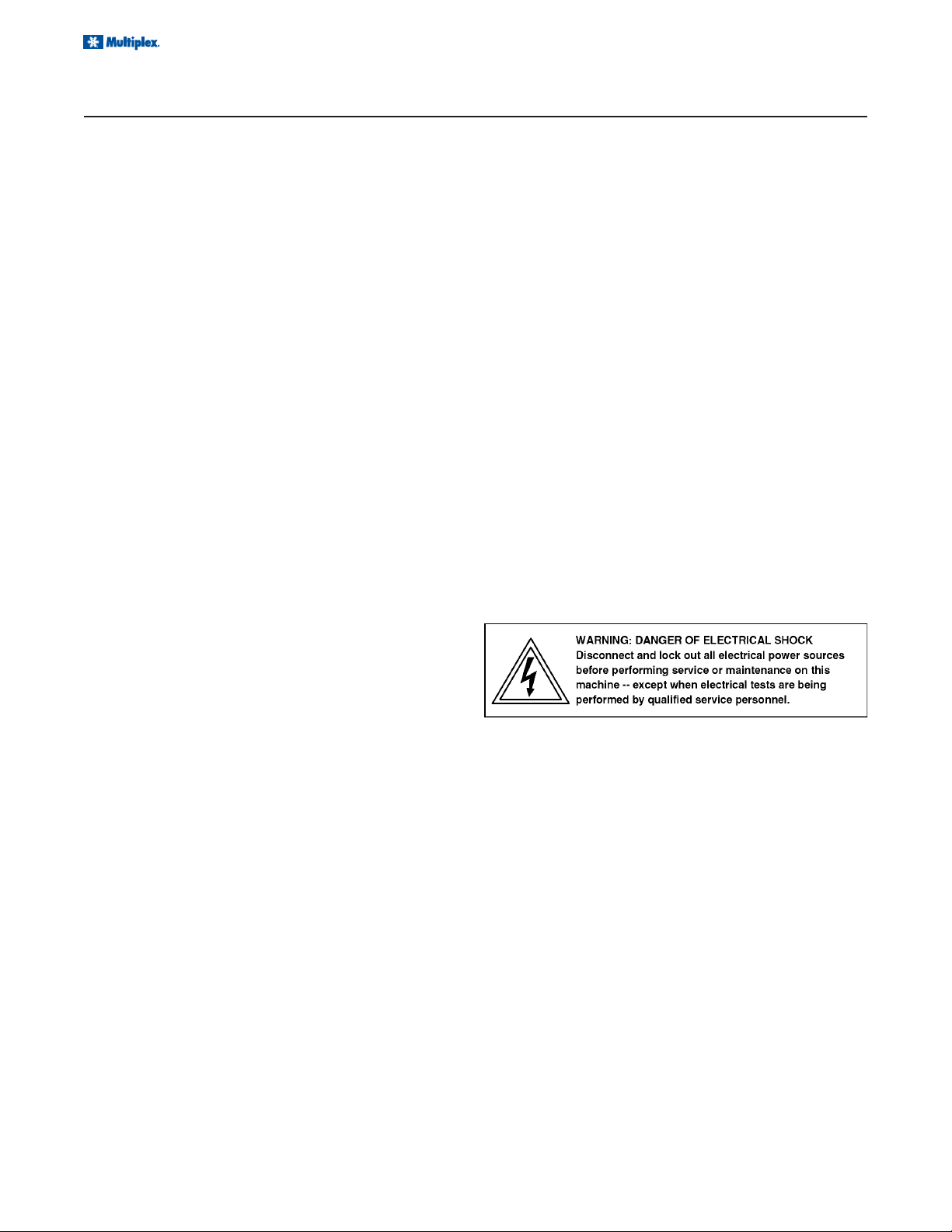
QUALIFIED SERVICE PERSONNEL
CAUTION: Only trained and certified electrical and plumbing technicians should service this unit.
All wiring and plumbing must conform to national and local codes.
gas leak
2
2
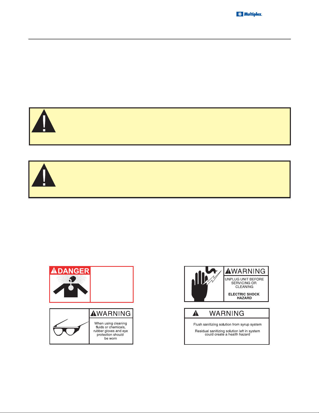
ADDITIONAL WARNINGS
Installation of this equipment should be done by a qualified service technician. Operation, maintenance,
and cleaning information in this manual are provided for the user/operator of the equipment.
Breathing high
concentrations of carbon
dioxide gas can cause
tremors, followed by loss
of consciousness and
suffocation
Route CO
CO2 DISPLACES OXYGEN
vent tube
2
outside or to an
unconfined area
5
Page 6
Installation and Service Manual
SAFETY
Caution: To Avoid Serious Injury
Important: Read the following warnings before beginning an installation. Failure to do so may result in possible
death or serious injury.
DO Adhere to all National and Local Plumbing and Electrical Safety Codes.
DO Turn “off” incoming electrical service switches when servicing, installing, or repairing equipment.
DO Check that all flare fittings are tight. This check should be performed with a wrench to ensure a quality seal.
DO Inspect pressure on Regulators before starting up equipment.
DO Protect eyes when working around refrigerants.
DO Use caution when handling metal surface edges of all equipment.
DO Handle CO
DO Store CO2 cylinder(s) in well ventilated areas.
DO NOT Exhaust CO2 gas (example: beer pump) into an enclosed area, including all types of walk in coolers,
DO NOT Throw or drop a CO2 cylinder. Secure the cylinder(s) in an upright position with a chain.
DO NOT Connect the CO2 cylinder(s) directly to the product container. Doing so will result in an explosion
DO NOT Store CO2 cylinders in temperature above 125°F (51.7°C) near furnaces, radiator or sources of heat.
DO NOT Release CO2 gas from old cylinder.
DO NOT Touch Refrigeration lines inside units, some may exceed temperatures of 200°F (93.3°C).
Notice: All utility connections and fixtures shall be
sized, installed and maintained in accordance with
Federal, State, and Local codes.
cylinders and gauges with care. Secure cylinders properly against abrasion.
2
cellars, and closets.
causing possible death or injury. Best to connect the CO2 cylinder(s) to a regulator(s).
FLAME AND SMOKE RATING
INSUL-TUBE® Pipe Insulation in wall thickness of 1" (25 mm) and below has a flame spread rating of 25 or less
and a smoke development rating of 50 or less as tested by ASTM E 84 Method of Testing entitled: Surface Burning
Characteristics of Building Materials. Duct/Plenum Applications INSUL-TUBE® is acceptable for duct/plenum
applications, meeting requirements of NFPA 90A.
Numerical flammability ratings alone may not define the performance of products under actual fire conditions. They
are provided only for use in the selection of products to meet limits specified, when compared to a known standard.
SPECIFICATION COMPLIANCE
ASTM C 534 Type 1 (Tubing)
ASTM D 1056-00-2C1
ASTM C 1534-02
New York City MEA 186-86-M Vol. IV
USDA Requirements
UL 94-5V Flammability Classification (Recognition No.
E147665)
ASTM E 84 1" 25/50-tested according to UL 723 and
NFPA 255
Complies with requirements of CAN/ULC S102-M88
6
NFPA No. 101 Class A Rating
Meets requirements of NFPA 90A Sect. 2.3.3 for
Supplementary Materials for Air Distribution Systems.
Meets requirements of ASTM C 411 (Tested Method of
Hot Surface Performance of High Temperature Thermal
Insulation).
Meets requirements of UL 181 sections 11.0 and 16.0
(Mold Growth/Air Erosion)
MIL-P-15280, For T (Tubing)
Page 7
Installation and Service Manual
SAFETY
SHIPPING, STORAGE, AND RELOCATION
CAUTION: Before shipping, storing, or relocating this unit, syrup systems must be sanitized. After
sanitizing, all liquids (sanitizing solution and water) must be purged from the unit. A freezing environment causes residual sanitizing solution or water remaining inside the unit to freeze, resulting
in damage to internal components.
Store conduit in 60°F (15.5°C) to 80°F (16.6°C) environment.
Keep in a cool, dry location.
Do not expose to direct sunlight.
Do not store conduit outside the original carton.
Do not store conduit for more than one year.
Do not store anything directly on top of conduit.
Do not store in an enclosed location with high aromatic compounds.
Conduit warranty is 2 years from date of manufacture as printed on the conduit.
If you have any questions or concerns, please contact the MBE Service Department at 800-3674233 or service@servend.com
7
Page 8
Installation and Service Manual
PRE-INSTALLATION
REQUIRED TOOLS
• Steel Fish Tape
• Length of Rope
• Duct Tape
UNPACKING AND INSPECTING
Carefully inspect the conduit immediately upon unpacking. Inspect conduit for any damages that may have occurred during shipping.
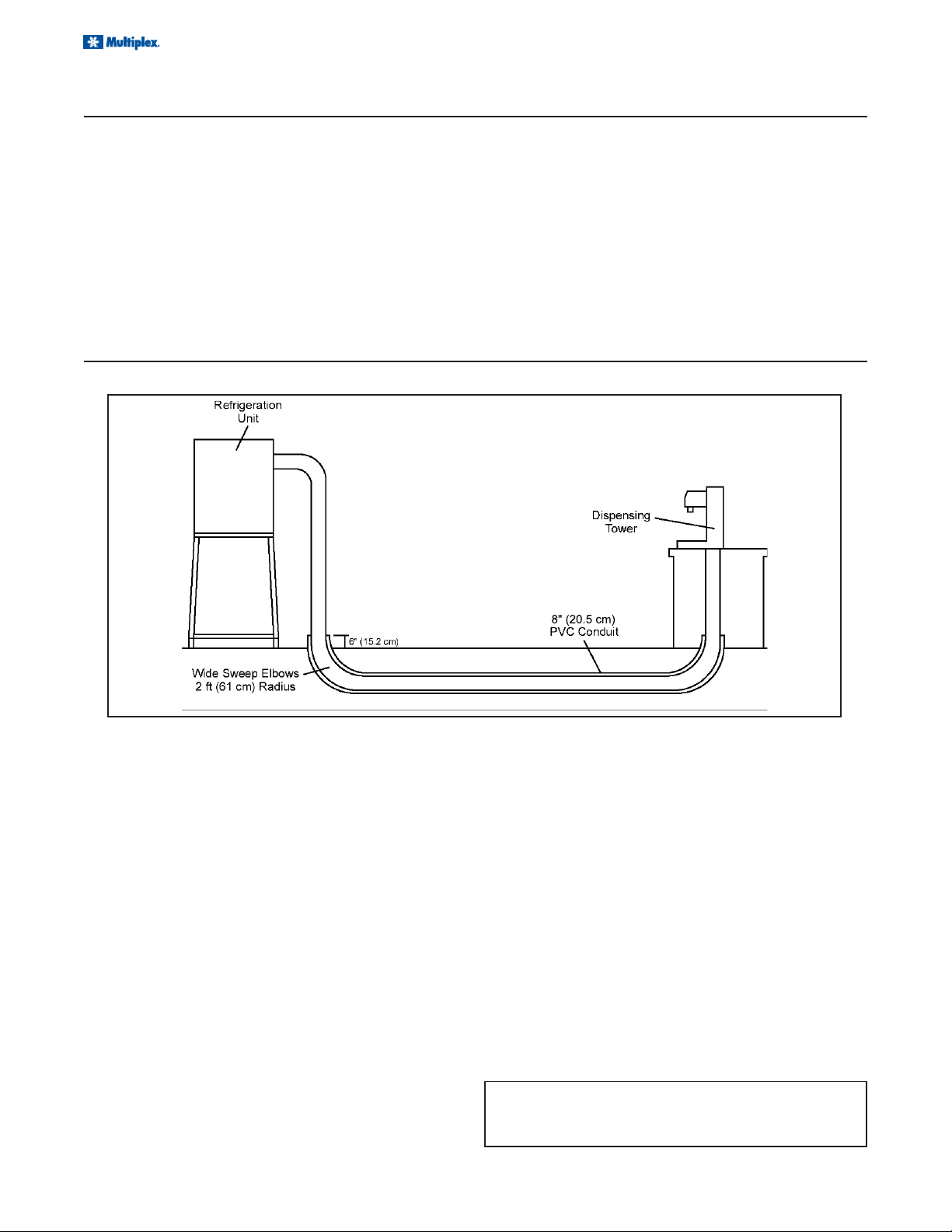
ROUTING MULTIPLEX CONDUIT
FLOOR CHASES
FIGURE 1
• Approved Tubing Cutters
• Razor Blade Knife
• Tab Clamp Pliers
Before installing conduit, be sure conduit is proper length
for installation, contains the correct number of lines for
connection, and all lines are proper diameter.
Before pulling Multiplex conduit through a floor chase, ensure the floor chase contains the following:
• 8" Minimum PVC Conduit
• Wide Sweep Elbows with a minimum 2 ft
(61 cm) radius
Pulling Conduit Through Floor Chase
1. Determine the most convenient way of routing conduit, starting at the end which offers adequate room
for installation. The conduit installation process requires the assistance of two (2) qualified personnel.
2. Locate steel fish tape and route through chase opening. Route fish tape through entire chase until it appears at opposite end.
3. Locate an appropriate length of rope and tie to end
of fish tape (end that was routed through chase in
step 2). Approximately 2 ft (61 cm) from steel fish
tape/rope connection, secure a swab to rope (use
mop heads or bundle of rags for swab).
4. Pull end of fish tape from starting point through chase
with rope and swab. The swab will sweep clean any
construction materials, moisture, or debris that may
exist in floor chase.
• Chase openings should extend 6" (15.2 cm)
above floor
• Chase must be clean and dry, no foreign materials
Caution: All objects and moisture must be removed from
floor chase before conduit can be routed. It may be necessary to repeat this process to ensure floor chase is clean.
5. After floor chase has been cleaned, remove steel
fish tape and swab from rope. Locate bundle of Multiplex conduit and unspool conduit to allow unrestricted feed during installation process.
6. Locate rope through chase opening and connect to
proper end of Multiplex conduit.
Note: Multiplex conduit is designed to be pulled
through a chase in the direction of arrows printed on
conduit
(refer to figure 2)
.
8
Page 9

Installation and Service Manual
ROUTING MULTIPLEX CONDUIT
ROUTING MULTIPLEX CONDUIT
7. After rope has been connected, tape end of conduit, including rope, and form conduit end to a point.
Tape will ensure that no contaminants enter conduit
tubes during installation.
8. Place pointed end of Multiplex conduit through chase
opening. While one person pushes the conduit
through chase, another person should be pulling
conduit through chase with rope on opposite end.
FIGURE 2
SEALING INSTRUCTIONS
Aerosol foam is to be used to fill the openings between the conduit insulation and the inside diameter of the floor
chases. The purpose is to provide an air tight seal at the floor level to prevent foreign matter from entering the chases.
Note: Please read the manufacturer’s instructions carefully.
9. Once conduit has been routed through chase, pull
enough conduit through openings to ensure an adequate supply at each end of chase for connections.
1. If the opening is too deep, insert a section of the
excess conduit insulation in the opening prior to using
the foam insulation.
2. Make sure all exposed carbonated water and syrup
lines are well insulated: towers to conduit; conduit
junctions, remote unit to conduit; drive thru junction.
Note: A little extra time spent doing a professional job
initially will eliminate a call back in several days to make
corrections.
OVERHEAD INSTALLATION
3. Use aluminum foil (if used), and tape, packed in the
inner pack carton to insulate these connections.
4. Cut the conduit sections to fit like a glove over the
exposed lines and fittings.
Warning: Do not inject foam material directly on the
connections where the tubing connects to the barb
fittings.
FIGURE 3
1. Determine the correct location for routing Multiplex
conduit. Be sure to avoid heat ducts, hoods, grills,
or any sharp objects that may exist above drop ceiling tile.
2. Unspool Multiplex conduit to allow unrestricted feed.
3. Conduit hangers should be spaced no more than 6
ft centers
Once conduit has been routed, ensure an adequate supply of conduit is provided at each end to make all connections
(refer to figure 3)
4. Route conduit above ceiling tiles and connect to ceiling and/or pipes using the appropriate conduit hangers. Be sure conduit is suspended above ceiling tiles.
Concern should be given when determining appropriate method of hanging conduit securely. Hangers must not crush or pinch insulation. This will reduce cooling efficiency.
9
Page 10

Installation and Service Manual
ROUTING MULTIPLEX CONDUIT
BASEMENT CONSTRUCTION
FIGURE 4
1. Unspool Multiplex conduit to allow unrestricted feed
during installation process.
2. Route the conduit up basement wall and secure
with appropriate conduit hangers.
Caution: Don't crush or pinch conduit insulation with hangers.
3. Conduit hangers should be spaced no more than 6
ft centers
Once conduit has been routed, ensure an adequate supply of conduit is on hand to make all connections.
4. Route conduit above ceiling tiles and connect to ceiling and/or pipes using the appropriate conduit hangers. Be sure conduit is suspended above ceiling tiles.
Concern should be given when determining appropriate method of hanging conduit securely. Hangers must not crush or pinch insulation. This will reduce cooling efficiency.
HOW TO CONNECT THE MULTIPLEX CONDUIT
Caution: Only an approved cutting tool should be
used to cut polyethylene tubing. Use a new blade so
that the tubing will not be crushed when cutting.
FIGURE 5
All Multiplex conduit syrup lines, carbonated water lines,
and the plain water line are coded for quick identification
and easy installation.
1. Locate the lines of Multiplex conduit routed at refrigeration unit and dispensing tower.
2. Using an approved razor knife, cut Multiplex conduit insulation by slicing along top side while peeling insulation back at the same time.
3. For soda systems, connect each syrup line, carbonated water line, and plain water line to the appropriate stainless steel coil in refrigeration unit.
For Glycol systems, connect to bulkhead fittings.
Note: Conduit lines should be long enough to allow
adequate work space when servicing equipment.
FIGURE 6
Note: Stainless steel cooling coils in our refrigeration units may contain either barb fittings or John Guest
fittings, depending on model. Before connecting conduit, identify whether the conduit is thick wall or thin wall
tubing (see illustration). Thick wall tubing should only be used with barb stem fittings. John Guest fittings can
only be used with thin wall tubing
10
Page 11

Installation and Service Manual
ROUTING MULTIPLEX CONDUIT
CONDUIT IDENTIFICATION CHART
When suspending Multiplex conduit with conduit hangers, the maximum allowable distance between hangers is 6
ft (1.82 m).
If ambient temperature of the conduit location is 90ºF (32.2ºC) or above, double insulated conduit must be utilized.
COLOR AND NUMBER CODING
I.D. Size of Tub e / Hose Number Color Suggested Use Tab Clamp Size
1/4" Tube S1 White Syrup 10.5
S2 Black
S3 Orange
S4 Red
S5 Blue
S6 Green
S7 Purple
S8 Brown
S9 Pink
S10 Ye llow
S11 White
S12 Black
S13 Orange
S14 Red
S15 Blue
S16 Green
11
Page 12

Installation and Service Manual
ROUTING MULTIPLEX CONDUIT
COLOR AND NUMBER CODING
I.D. S iz e of Tub e / H ose Number Color Suggested Use Tab Clamp Size
3/8" Tube AF Red Water / Glycol 13.8
½" Tube VS1 Orange High Viscous Syrup 17.0
½" H ose AF Blue Water / Glycol 18.5
Product suggestions for conduit tubing
AR Red
BF Blue
BR Blue
S1 White Syrup / Beer 13.8
S2 Black
S3 Orange
S4 Red
S5 Blue
S6 Green
S7 Purple
S8 Brown
S9 Pink
S10 Yellow
S11 White
S12 Black
S13 Orange
S14 Red
S15 Blue
S16 Green
VS2 Natural
VS3 Green
VS4 White
VS5 Black
VS6 Red
VS7 Blue
VS8 Purple
VS9 Brown
VS10 Pink
VS11 Yellow
VS12 Purple
AR Blue
BF Yellow
BR Yellow
WF Black
WR Black
Current conduit tubing is PTE lined. Therefore it is no longer necessary to make sure pungent flavors are used with
specific tubing. Keeping with that process, when connecting conduit to syrup boxes and valves, the best flavor/
tubing selection would be to utilize line number S1 for valve number 1, S2 for valve number 2, etc.
12
Page 13

ROUTING MULTIPLEX CONDUIT
ROUTING MULTIPLEX CONDUIT
Barb Stem Fittings
1. Moisten barbed fittings with warm water.
2. Connect appropriate lines to barbed fittings and secure with two (2) tab clamps. Tab clamps should
be staggered when connecting
(refer to figure 7)
.
Installation and Service Manual
2. Once the end of each line has been cut, lubricate
with water and insert line into John Guest Fitting.
Be sure the tubing is inserted firmly through O-ring
in John Guest fitting.
3. Connect each syrup line, carbonated water line, and
plain water line to the appropriate connection in dispensing tower. Secure with two (2) tab clamps. If
tower has barbs, a John Guest adapter stem should
be used when connecting to a conduit with John
Guest Fittings.
FIGURE 7
John Guest Fittings
1. Before inserting appropriate conduit lines to John
Guest fittings, ensure that the end of each line is
cut square at a 90° angle.
TEEING INTO THE MULTIPLEX CONDUIT ON SODA SYSTEMS
1. Locate the section in main conduit where tee connections are to be made. Measure a 12" (30.5 cm)
area in the designated section.
2. Using a razor knife, cut a “X” pattern in designated
section as shown in figure 8. Peel back the ends of
foam insulation and identify each syrup line and
water line located in conduit. Be careful not to cut
lines inside conduit. Even a small “nick” will result
in leaks.
FIGURE 9
Note: Connections in dispensing towers may contain
either barb stem fittings or John Guest fittings. See
previous section for proper instruction.
FIGURE 10
4. Locate the section of tee conduit. Using a razor
knife, slice foam insulation in a straight line on top
side of conduit. Pull back foam insulation and locate each syrup line
(refer to figure 11)
.
FIGURE 8
3. Using a tubing cutter, cut each syrup line (one [1]
line at a time) in main conduit. Locate barbed tees
in conduit tee kit, connect to each syrup and water
line. Secure with two tab clamps
(refer to figure 10)
.
FIGURE 11
13
Page 14

Installation and Service Manual
TEEING INTO THE MULTIPLEX CONDUIT ON SODA SYSTEMS
ROUTING MULTIPLEX CONDUIT
5. Connect each syrup line in a tee conduit to the appropriate barbed tee connected to the syrup lines
in the main conduit. Secure with two (2) tab clamps
(refer to figure 10)
sponding to the main conduit markings.
6. Locate carbonated water lines in main conduit and
cut using tubing cutter. Locate barbed “Ell” fitting
provided in kit and connect to carbonated water
lines
(refer to figure 12)
7. Connect the carbonated water lines in tee conduit
to the appropriate barbed ells connected to carbonated water lines in main conduit. Secure with
two tab clamps
Note: The number of carbonated water lines will vary
depending on the model of the refrigeration unit.
. Be sure to tee line markings corre-
.
FIGURE 12
(refer to figure 13)
.
8. Pull the sliced sections of foam insulation back over
openings where connections were made. Using
cloth tape, tape over openings and seal air tight.
9. After ensuring there are no leaks at conduit connections, wrap foam insulation tape around the
sliced sections and insulate the Multiplex conduit
completely. This is very important to prevent condensation and loss efficiency.
10. Seal each chase opening by spraying foam insulation into each end of chase opening. This will reduce risk of contamination of conduit in chase.
14
FIGURE 13
Page 15

ROUTING MULTIPLEX CONDUIT
CONDUIT KIT
FIGURE 14
Installation and Service Manual
FIGURE 15
FIGURE 16
15
Page 16

Installation and Service Manual
BEERMASTER BEER CONDUIT
INTRODUCTION
The following instructions will provide information for installing Multiplex/Multiplex Beer Conduit with your Beermaster
System. Areas which will be covered include routing the conduit for different bar set-ups, connecting the conduit at
the Beermaster Glycol Chiller, connecting the conduit at the beer cooler, and connecting the conduit at the dispensing stations.
FLOOR CHASES
Before pulling beer conduit through a floor chase, ensure the floor chase contains the following
(see Figure 1)
• 6" (minimum) PVC conduit chase
• Wide sweep elbows (2 ft radius)
• Chase openings should extend 6" above floor
• Chase must be clean and dry–no foreign materials
FIGURE 1
Pulling conduit through floor chase
1. Determine the most convenient way of routing conduit, starting at the end which offers adequate room
for installation. The conduit installation process requires the assistance of at least two (2) qualified
personnel.
2. Route the steel fish tape through chase opening.
Push fish tape through entire chase until it appears
at opposite end.
3. Locate an appropriate length of rope and tie to end
of fish tape (end which was routed through chase
in step 2). Approximately 2 ft from steel fish tape/
rope connection, secure a swab to rope (use mop
heads or a bundle of rags for swab).
16
4. Pull end of fish tape from starting point through
chase with rope and swab. The swab will clean
any construction materials, moisture, or debris that
may exist in floor chase. Continue to swab the
chase until the swab exits the chase clean and dry.
5. After floor chase has been cleaned, remove steel
fish tape and swab from rope. Locate bundle of
beer conduit and unspool conduit to allow unrestricted feed during installation process.
6. Locate rope through floor chase opening and connect to proper end of beer conduit.
Note: The beer conduit is designed to be pulled
through floor chase in the direction of arrows printed
on conduit.
Page 17

BEERMASTER BEER CONDUIT
FLOOR CHASES
FIGURE 2
7. After rope has been connected, tape end of conduit, including rope, and form conduit end to a point
(see Figure 2)
enter conduit tubes during installation.
. Tape will ensure that no contaminants
OVERHEAD INSTALLATION
Installation and Service Manual
8. Place pointed end of the conduit through chase
opening. While one person pushes the conduit
through chase, another person should be pulling
the conduit through the chase with rope at the opposite end.
9. Once the conduit has been routed through the
chase, pull enough conduit through the openings
to ensure an adequate supply at each end of the
chase for connections.
Refer to Figure 3 for the following:
1. Determine the correct location for routing the beer
conduit. Be sure to avoid heat ducts, hoods, grills,
or any sharp objects that may exist above drop ceiling tile.
2. Unspool the beer conduit to allow unrestricted feed.
3. Route the conduit above ceiling tiles and connect
to ceiling and/or pipes using the appropriate conduit hangers. Be sure the conduit is suspended
FIGURE 3
above ceiling tiles, not lying on the tiles. Care should
be taken when determining appropriate method of
handing conduit securely. Hangers must not crush
or pinch insulation. This will reduce cooling efficiency.
4. Once the conduit has been routed, ensure an adequate supply of conduit is provided at each end
to make all connections.
17
Page 18

Installation and Service Manual
BEERMASTER BEER CONDUIT
BASEMENT CONSTRUCTION
FIGURE 4
Refer to Figure 4 for the following:
1. Unspool the beer conduit to allow unrestricted feed
during installation process.
2. Route the conduit up basement wall and secure
with appropriate conduit hangers.
3. After routing the conduit up the basement wall, route
conduit overhead on the basement ceiling. Con-
nect to the basement ceiling using appropriate conduit hangers.
4. Once the conduit has been routed, ensure an adequate supply of conduit is on hand to make all
connections.
CONNECTING BEER CONDUIT
Before connecting the beer conduit at the walk-in beer cooler and beer towers, ensure an adequate length of
conduit is being supplied to make proper connections.
CAUTION: Only an approved cutting tool should be used to cut polyethylene tubing. The cutting tool should
contain a razor sharp cutting blade so that the tubing will not be crushed when cutting. A razor blade knife
or butterfly tubing cutter is sufficient (
Glycol Chiller.
FIGURE 5
see Figure 5
). Multiplex packs a butterfly cutter with each Beermaster
1. Locate the lines of the beer conduit routed to the
Beermaster Glycol Chiller.
2. Using an approved cutting tool, cut the beer conduit insulation along the top side while peeling insulation back at the same time.
Note: Glycol circuit is a pair of lines; one blue and
one red. The blue line is the discharge or supply line.
The red line is the return line.
18
Page 19

BEERMASTER BEER CONDUIT
CONNECTING BEER CONDUIT
FIGURE 5
Installation and Service Manual
3. Locate the return glycol supply lines of the beer
conduit and connect to the corresponding John
Guest fitting on the Beermaster Glycol Chiller.
4. Locate the discharge glycol supply lines of the beer
conduit and connect to the corresponding John
Guest fitting on the Beermaster Glycol Chiller.
5. Locate the glycol lines in the main conduit. Connect the glycol lines of the beer unit to walk-in cooler
conduit to the glycol lines of the main beer conduit.
6. Locate the beer and glycol supply lines at the dispensing station. Connect each beer line, incoming
glycol line, and outgoing glycol line to the appropriate John Guest fitting at the dispensing station.
CONDUIT KIT
General
The following instructions will cover installation procedures required for properly connecting each component of
the Beermaster system. These instructions also contain the necessary information required for; calculating restrictor
line length, required regulator operating pressures and start up procedures. It is recommended that before proceeding with these instructions you ensure that each of the following items have been properly installed. Items
listed in suggested order of installation:
1. Glycol Chiller Unit,
2. Dispensing Towers,
3. Secondary Regulator Kits,
4. Beer Conduit,
Once the above items have been installed the following instructions can be completed.
Note: Your system may not include each item.
5. High Pressure CO2 Regulator Kit,
6. Blender Kit or Beer Pumps
7. Air Compressor Kit, (optional)
8. Low CO2 Alarm Kit.
Kit contents
Four (4) and Seven (7) line conduit kits
• Three (3) Return bends
• Eight (8) Elbows
• 29 Unions
• Five (5) Tail pieces
• Five (5) Beer nuts
• One (1) 60 ft of PVC tape
• One (1) 60 ft of foil
• One (1) Spanner wrench
10 and 14 line conduit kits
• Four (4) Return bends
• 15 Elbows
• 42 Unions
• Eight (8) Tail pieces
• Eight (8) Beer nuts
• One (1) 60 ft of PVC tape
• One (1) 60 ft of foil
• One (1) Spanner wrench
19
Page 20

Installation and Service Manual
BEERMASTER BEER CONDUIT
CONDUIT KIT
FIGURE 6
FIGURE 7
FIGURE 8
20
Page 21

Installation and Service Manual
BEERMASTER BEER CONDUIT
INSTALLING THE CONDUIT KIT
Connections preview
Review Figures 6, 7 and 8 to determine which best illustrates your particular installation. Consider the following
while examining the drawings:
Beer conduits have been designed to achieve the proper
cooling of each encased beer line. In order to function
properly, you must follow these guidelines:
To insure colder dispensing temperatures, glycol should flow directly to the dispensing towers before returning to
the remote Glycol Chiller Unit. After examining the drawings determine the desired glycol circuit to be achieved and
illustrate on paper for referral. Do the same for the assignment of the beer supply lines.
Up to eight (8) line conduit:
• six (6) beer maximum, one (1) glycol circuit (two [2] lines)
Ten (10) and over line conduit:
• two (2) glycol circuits (four [4] lines)
Connecting the glycol chiller to the walk-in cooler or
main beer conduit
1. Route the glycol conduit(s) from the Beermaster
Glycol Chiller to the point of connection on the main
beverage conduit(s). This connection could be done
in the walk-in cooler or at any desired location along
the length of the main beer conduits.
2. Identify the proper glycol lines within the glycol
conduit(s) at the Beermaster Glycol Chiller, cut to
length and insert into the appropriate John Guest
bulkhead fitting(s) found on the side panel of the
Beermaster Glycol Chiller (see Figure 9).
Connecting main beer conduit at walk-in cooler
1. At the top of each beer wall bracket fitting, found
on the dual secondary regulator, secure a Beer Nut,
John Guest adapting tail piece, washer, and 1/2"
John Guest union (see Figure 10).
2. Identify the appropriate beer lines to be connected
to each of the wall bracket fittings, cut to length
and insert into the proper John Guest 1/2" connector (see Figure 10).
FIGURE 9
3. At the walk-in end of the conduit(s), peel back the
insulation from the beer conduit and identify the
appropriate glycol circuit and lines to be connected
(blue and red). Cut glycol lines and secure to the
appropriate elbow or union connections that are
best suited for connection with the beer conduit.
FIGURE 10
Connecting beer conduit to the tower
Glycol lines in
1. Peel the insulation back from the end of the beer
conduit to expose all lines. Locate the appropriate
glycol circuit lines, cut to length and attach a 1/2"
John Guest union to each line (see Figure 11).
2. Attach the opposite end of each 1/2" John Guest
unions to the 1/2" adaptors located at the base of
the dispensing tower (see Figure 11).
21
Page 22

Installation and Service Manual
BEERMASTER BEER CONDUIT
INSTALLING THE CONDUIT KIT
FIGURE 11
Note: If conduit contains more than one glycol circuit it will be necessary to attach U-bends for each of the
additional circuits. Use a 1/2" U-bend quick connect fitting or the U-bend can be built by attaching two (2)
1/2" John Guest elbows to one another by means of a 2" length of 1/2" tubing.
BEER RESTRICTOR LINES
1. Cut each restrictor line to the calculated length and
carefully insert the 3/16" Barb x 1/2" John Guest
adaptor and clamp securely with the adjustable
clamps provided (see Figure 11).
2. Identify the beer line to be connected to each of
the appropriate restrictor line, cut the beer lines to
length and attach a 1/2" John Guest Union to each.
Neatly wrap the excess restrictor line securely
around the glycol supply lines to ensure good heat
exchange. Connect the adaptor from each restrictor
to the 1/2" connector of each of the appropriate
beer lines.
Connecting main beer conduit to branch beer conduit
1. At the required point of connection carefully split
open and fold back the insulation on the main beer
conduit and identify the correct set of glycol lines
(circuit) to connect to the branch beer conduit. Cut
the glycol line(s) and attach the appropriate 1/2"
elbow or union connections that are best suited to
connecting with the main beer conduit
(see Figure 12).
2. Peel the insulation back from the end of the branch
beer conduit to expose all lines. Locate the glycol
circuit lines, cut to length and insert each line into
the open end of the previously attached 1/2" con-
nectors at the main beer conduit (see Figure 12).
3. Locate the appropriate beer line(s) in the main beer
conduit to be connected to the branch conduit. Cut
desired beer line(s) long so that they can be pulled
back and then routed in a smooth curve into the
branch conduit. Attach appropriate beer line(s) from
main beer conduit to beer line(s) in branch beer
conduit with 1/2" John Guest Union(s).
Caution: To avoid agitation use only straight unions when
splicing beer lines.
22
FIGURE 12
Page 23

INDEX
B
Basement ................................ 18
beer cooler .............................. 18
Beer nuts................................. 19
branch ..................................... 22
brixing ....................................... 3
C
Carbon Dioxide ......................... 5
CAUTION ............................. 4, 6
chase ...................................... 16
Cleaning .................................... 3
CO2 ...................................... 4, 6
CO2 monitors ............................ 4
Conduit................ 16, 17, 18, 19
conduit chase .......................... 16
Conduit Kit ... 15, 19, 20, 21, 22
Connecting ................ 18, 19, 22
construction ............................ 18
cooler ...................................... 18
D
distributor .................................. 3
E
Elbows .................................... 19
Electrical Safety Codes ............. 6
F
Floor chases .................... 16, 17
FOREWORD ............................ 3
G
Glycol ...................................... 21
I
Information ................................ 5
INSPECTION ............................ 3
installation ............................... 17
Installation Date ........................ 3
Introduction ............................. 16
L
lines ......................................... 21
M
MBE .......................................... 3
Model Number .......................... 3
modifications ............................. 5
O
Operation .................................. 5
Overhead ................................ 17
P
Plumbing ................................... 6
PVC ......................................... 16
PVC tape ................................. 19
Q
Qualified Service Personnel ..... 5
R
restrictor line ........................... 22
Return bends .......................... 19
return procedures ..................... 3
S
SAFETY ........................... 5, 6, 7
sanitizing ................................... 7
Serial Number ........................... 3
Service Personnel ..................... 5
Spanner wrench ...................... 19
sweep ...................................... 16
T
Tail pieces ............................... 19
tower ....................................... 21
towers ..................................... 18
U
UNPACKING ............................. 3
W
walk-in .............................. 18, 21
WARNING ................................. 4
Warning ..................................... 5
WARRANTY INFORMATION ... 3
Page 24

Manitowoc Beverage Equipment
2100 Future Drive Sellersburg, IN 47172-1868
Tel: 812.246.7000, 800.367.4233 Fax: 812.246.9922
www.manitowocbeverage.com
In accordance with our policy of continuous product development and
improvement, this information is subject to change at any time without notice.
EI211017 May 04, 2007 REV2
 Loading...