

Page 1
1
GB
D
E
I
Bauanleitung 03 ... 10
Building instructions 11 ... 19
Notice de construction 20 ... 33
Istruzioni di montaggio 34 ... 41
Instrucciones de montaje 42 ... 49
© Copyright by MULTIPLEX 2012 Version 2.0
F
PRO
vorgesehen für die MULTIPLEX
Brushless-Antriebe # 33 3651 u. # 33 3650
oder als Segler
KIT # 21 4226
KIT # 21 4271
Page 2

2
D
F
GB
I
E
Sicherheitshinweise
Prüfen Sie vor jedem Start den festen Sitz des Motors und der Luftschraube - insbesondere nach dem Transport, härteren
Landungen sowie Abstürzen. Prüfen Sie ebenfalls vor jedem Start den festen Sitz und die richtige Position der Tragflächen auf
dem Rumpf.
Akku erst einstecken, wenn Ihr Sender eingeschaltet ist und Sie sicher sind, daß das Bedienelement für die Motorsteuerung auf
"AUS" steht.
Im startbereiten Zustand nicht in den Bereich der Luftschraube greifen.
Vorsicht in der Luftschraubendrehebene - auch Zuschauer zur Seite bitten!
Zwischen den Flügen die Motortemperatur durch vorsichtige Fingerprobe prüfen und
vor einem Neustart den Motor ausreichend abkühlen lassen. Die Temperatur ist richtig, wenn Sie den Motor problemlos berühren
können. Insbesondere bei hohen Außentemperaturen kann dieses bis zu 15 Minuten dauern.
Denken Sie immer daran: Niemals auf Personen und Tiere zufliegen.
Conseils de sécurité
Avant chaque décollage, vérifiez la fixation du moteur et de l'hélice, notamment après le transport, après les atterrissages
violents et après un “Crash”. Vérifiez également, avant chaque décollage la fixation ainsi que le positionnement de l’aile par
rapport au fuselage.
Ne branchez l’accu de propulsion que si vous êtes sûr que votre émetteur est allumé et que l’élément de commande moteur est
en position “ARRET”.
Ne mettez pas vos doigts dans l’hélice! Attention à la mise en marche, demandez également aux spectateurs de reculer.
Entre deux vols, vérifiez en posant un doigt dessus, la température du moteur, laissezle refroidir suffisamment avant le prochain
décollage. La température est correcte si vous pouvez maintenir votre doigt ou votre main sur le moteur. Le temps de refroidissement
peut varier jusqu’à 15 minutes s’il fait particulièrement chaud.
Pensez-y toujours: ne volez jamais vers ou au-dessus des personnes ou des animaux.
Safety notes
Before every flight check that the motor and propeller are in place and secure - especially after transporting the model, and after
hard landings and crashes. Check also that the wing is correctly located and firmly secured on the fuselage before each flight.
Don’t plug in the battery until you have switched on the transmitter, and you are sure that the motor control on the transmitter is set
to “OFF”.
When the model is switched on, ready to fly, t ake care not to touch the propeller . Keep well clear of the propeller disc too, and ask
spectators to stay back.
Allow the motor to cool down after each flight. You can check this by carefully touching the motor case with your finger. The
temperature is correct when you can hold your finger on the case without any problem. On hot days this may take up to 15
minutes.
Please keep in mind at all times: don’t fly towards people or animals.
Note di sicurezza
Prima di ogni decollo controllare che il motore e la eliche siano fissati stabilmente - specialmente dopo il trasporto, atterraggi duri
e se il modello è precipitato. Controllare prima del decollo anche il fissaggio e la posizione corretta delle ali sulla fusoliera.
Collegare la batteria solo quando la radio è inserita ed il comando del motore è sicuramente in posizione ”SPENTO”.
Prima del decollo non avvicinarsi al campo di rotazione della eliche. Attenzione alla eliche in movimento - pregare che eventuali
spettatori si portino alla dovuta distanza di sicurezza!
Tra un volo e l’altro controllare cautamente con le dita la temperatura del motore e farli raffreddare sufficientemente prima di ogni
nuovo decollo. La temperatura è giusta se si possono toccare senza problemi. Specialmente con una temperatura esterna alta
questo può durare fino a 15 minuti.
Fare attenzione: Non volare mai nella direzione di persone ed animali.
Advertencias de seguridad
Compruebe antes de cada despegue que el motor y la hélice estén fuertemente sujetados, sobretodo después de haberlo
transportado, de aterrizajes más fuertes así como después de una caída. Compruebe igualmente antes de cada despegue que
las alas estén bien sujetas y bien colocadas en el fuselaje.
Conectar la batería, cuando la emisora esté encendida y Usted esté seguro que el elemento de mando para el motor esté en
”OFF”.
No meter la mano en la zona inmediata a la hélice cuando el avión esté a punto de despegar. ¡Cuidado con la zona de la hélice!
¡Pedir a los espectadores que se aparten!
Entre los vuelos hay que comprobar cuidadosamente la temperatura del motor con el dedo y dejar que el motor se enfríe antes
de volver a despegar. La temperatura es correcta, si puede tocar el motor sin problemas. Sobretodo en el caso de temperaturas
del ambiente muy altas, esto puede tardar unos 15 minutos.
Recuerde: No volar nunca hacía personas o animales.
Page 3
3
KIT EasyGlider PRO + electric Blue Edition
Machen Sie sich mit dem Bausatz vertraut!
MULTIPLEX - Modellbaukästen unterliegen während der Produktion einer ständigen Materialkontrolle. Wir hoffen, dass Sie mit
dem Baukasteninhalt zufrieden sind. Wir bitten Sie jedoch, alle Teile (nach Stückliste) vor Verwendung zu prüfen, da bearbeitete
Teile vom Umtausch ausgeschlossen sind. Sollte ein Bauteil einmal nicht in Ordnung sein, sind wir nach Überprüfung gerne zur
Nachbesserung oder zum Umtausch bereit. Bitte senden Sie das Teil an unsere Modellbauabteilung und fügen Sie unbedingt den
Kaufbeleg und eine kurze Fehlerbeschreibung bei.
Wir arbeiten ständig an der technischen Weiterentwicklung unserer Modelle. Änderungen des Baukasteninhalts in Form, Maß,
Technik, Material und Ausstattung behalten wir uns jederzeit und ohne Ankündigung vor. Bitte haben Sie Verständnis dafür, dass
aus Angaben und Abbildungen dieser Anleitung keine Ansprüche abgeleitet werden können.
Achtung!
Ferngesteuerte Modelle, insbesondere Flugmodelle, sind kein Spielzeug im üblichen Sinne. Ihr Bau und Betrieb erfordert
technisches Verständnis, ein Mindestmaß an handwerklicher Sorgfalt sowie Disziplin und Sicherheitsbewusstsein. Fehler
und Nachlässigkeiten beim Bau und Betrieb können Personen- und Sachschäden zur Folge haben. Da der Hersteller
keinen Einfluss auf ordnungsgemäßen Zusammenbau, Wartung und Betrieb hat, weisen wir ausdrücklich auf diese Gefahren hin.
Zusätzlich zum Modell EasyGliderPRO erforderlich:
Klebstoff:
Sekundenkleber „leicht verdickt“ (Cyanacrylat-Kleber) Zacki ELAPOR # 85 2727 verwenden - keinen Styropor-Sekundenkleber!
Epoxy Klebstoffe geben eine zunächst subjektiv brauchbare Verbindung, jedoch platzt der harte Kleber bei Belastung von den
Teilen ab. Die Verbindung ist nur oberflächlich. Alternativ kann auch Heisskleber verwendet werden!
MULTIPLEX Fernsteuerelemente für EasyGlider PRO:
Empfänger RX-5 light M-Link Best.-Nr. 5 5808
oder Empfänger RX-5 M-Link (telemetriefähig) Best.-Nr. 5 5817
Servo Tiny-S (2x erforderlich) Höhe / Seite Best.-Nr. 6 5121
Servo Nano-S (2x erforderlich) Quer Best.-Nr. 6 5120
oder Tuning-Servo Tiny-MG (2x erforderlich) Höhe / Seite Best.-Nr. 6 5122
Tuning-Servo Nano-PRO MG (2x erforderlich) Quer Best.-Nr. 6 5119
Verlängerungskabel 400 mm UNI (2x erforderlich) Querruderservo Best.-Nr. 8 5029
Verlängerungskabel 300 mm UNI (2x erforderlich) Querruderservo Best.-Nr. 8 5031
Ladegerät:
MULTIcharger L-703 EQU 230V Best.-Nr. 9 2523
oder Combo MULTIcharger LN-3008 EQU mit 230V Netzteil 5A Best.-Nr. 9 2545
Antriebsatz EasyGlider PRO
Antriebssatz "EasyGlider PRO 3S STANDARD" Li-BATT powered Best.-Nr. 33 3651
Antriebssatz "EasyGlider PRO 3S STANDARD" Best.-Nr. 33 2651
Tuning-Antriebsatz EasyGlider PRO
Antriebssatz "EasyGlider PRO 3S TUNING" Li-BATT powered Best.-Nr. 33 3650
Antriebssatz "EasyGlider PRO 3S TUNING" Best.-Nr. 33 2650
Antriebsakku
Li-BATT eco 3/1-2000 (M6) 2000 mAh Best.-Nr. 15 7231
Li-BATT eco 3/1-3000 (M6) 3000 mAh Best.-Nr. 15 7236
Zusätzlich für die Seglervariante
Empfängerakku (NiMH) 4 / 2100mAh Best.-Nr. 15 6052
Mini - Schalterkabel mit Ladebuchse Best.-Nr. 8 5045
Schleppkupplung Best.-Nr. 72 3470
Werkzeuge:
Schere, Klingenmesser, Seitenschneider.
Hinweis: Bildseiten aus der Mitte der Bauanleitung heraustrennen!
Technische Daten: Segler Elektro Segler
Spannweite 1.800 mm 1.800 mm
Länge über alles 1.130 mm 1.130 mm
Fluggewicht ca. 800 g mit Serienantrieb ca. 980 g
Flächeninhalt FAI ca. 41,6 dm² FAI ca. 41,6 dm²
Flächenbelastung ca. 20 g/dm² ca. 24 g/dm²
RC-Funktionen Höhen-, Seiten- und Querruder zusäzlich Motorsteuerung
D
Page 4
4
Wichtiger Hinweis
Dieses Modell ist nicht aus Styropor ™! Daher sind Verklebungen mit Weißleim oder Epoxy nicht möglich. Verwenden
Sie nur Cyanacrylatkleber (Sekundenkleber), vorzugsweise in Verbindung mit Aktivator (Kicker). Für alle Verklebungen
verwenden Sie Cyanacrylatkleber in mittlerer Viskosität. Sprühen Sie bei Elapor® immer eine Seite mit Aktivator (Kikker) ein – lassen diesen 2 Minuten ablüften und geben Sie auf die andere Seite den Cyanacrylatkleber an. Fügen Sie die
Teile zusammen und positionieren Sie diese sofort.
Vorsicht beim Arbeiten mit Cyanacrylatklebern. Diese Kleber härten in Sekunden, daher nicht mit den Fingern und
anderen Körperteilen in Verbindung bringen. Zum Schutz der Augen unbedingt Schutzbrille tragen!
Von Kindern fernhalten!
5. Hochstarthaken einbauen
Beim Segelflugmodell wird nun der Hochstarthaken 32 in das
Formnest der Rumpfhälfte 4 geklebt.
Abb. 9
6. Einbau des Motorträgers
Den Motorträger 34 in die rechte Rumpfhälfte einkleben. Es soll
kein Kleber austreten und die später beim Zusammenbau zu verklebende Motorträgerhälfte soll jetzt noch frei von Klebstoff bleiben. Der Motorträger wird auch beim Segler aus Festigkeitsgründen eingebaut.
Abb. 10
7. Servos in die Rumpfhälften einbauen
Stellen Sie die Servos mit der Fernsteuerung auf „Neutral“ .
Die Servos wie in Abb. 11 gezeigt seitlich in die linke und rechte
Rumpfhälfte stecken. Bei Verwendung von anderen Servos, können kleinere Anpassarbeiten notwendig werden.
Die Servokabel von unten nach oben in die Aussparung legen
und mit Klebeband fixieren. Die Servos mit einem Tropfen CAKleber an den Laschen im Schaum befestigen. Nun die Z- Drähte
in die Servohebel einstecken und diese im Winkel von 90° auf
dem Servo montieren (Schraube nicht vergessen. Die
Verschlussklammern 22 rechts und links im Rumpf einkleben.
In die Kabelhalter 36 die Verlängerungskabel bündig einkleben.
Die Kabelhalter 36 rechts und links in die Formnester bis zum
Anschlag in die Rumpfhälften kleben. Die Kabel verlegen und
die Rumpflängsspanten 37 einkleben.
Abb.11
8. Zusammenkleben der Rumpfhälften
Der geeignete Kleber für diese Verbindung ist CA Kleber dickflüssig (Sekundenkleber) in Verbindung mit Aktivator.
Achtung: Bei der Tuning-Version (bei Motoren von ca. 135g)
werden zuvor noch die 2 Ausgleichsgewichte 33 wie in Abb.
12 gezeigt eingeklebt.
Die Rumpfhälften 3 + 4 werden zunächst noch ohne Klebstoff
geprüft, ob sich diese einwandfrei zusammenfügen lassen – ggf.
an entsprechender Stelle nacharbeiten.
Rumpfhälfte 4 mit Aktivator einsprühen und 2min. ablüften lassen.
Rumpfhälfte 3 an den Verbindungsstellen und auch am Motorträger mit Klebstoff versehen und mit 4 sorgfältig zusammenfügen und ausrichten! Die Rumpfnaht muss gerade verlaufen und
darf nicht gebogen sein!
Abb. 12
9. Seitenruderscharnier einbauen
Das Scharnier 31 mit wenig Sekundenkleber im Rumpfende
einkleben. Achten Sie insbesondere darauf, dass kein Kleber
in das Scharnier kommt.
Abb. 13
An der Vorderkante des Seitenruders mittig mit einem Klingen-
1. Vor dem Bau
Prüfen Sie den Inhalt Ihres Baukastens.
Dazu sind die Abb. 1+2 und die Stückliste hilfreich.
Fertigstellung des Rumpfes und der Leitwerke
2. Vorbereitung der Bowdenzüge
Die Länge der Höhenruder-Bowdenzugrohre 43 und 45
kontrollieren und ggf. kürzen.
43 Ø 3/2 x 785 mm
45 Ø 2/1 x 850 mm
Stahl 41 Ø 0,8 x 875 mm einstecken!
Ebenso mit den Seitenruder-Bowdenzugrohren 44 und 46
verfahren.
44 Ø 3/2 x 785 mm
46 Ø 2/1 x 850 mm
Stahl 42 Ø 0,8 x 875 mm einstecken!
Antennenrohr 47 Ø 3/2 x 785 mm (ggf. kürzen)
3. Einbau der Bowdenzüge in die Rumpfhälften
Achtung: Durch die sorgfältige Verklebung der Bowdenzugaus-
senrohre 43 und 44 sowie dem Antennenrohr 47 auf der gesamten Länge mit dem Rumpf entsteht ein erheblicher Stabilitätszuwachs am Leitwerksträger.
Achten Sie auch auf die Leichtgängigkeit der Bowdenzüge und
dass kein Klebstoff in das Bowdenzugrohr gelangt.
Linke Rumpfhälfte:
Den kompletten Höhenruder-Bowdenzug (Stahldrahtlänge =
875mm) in die linke Rumpfhälfte stecken. Die Z-Biegung zeigt
zum Servo.
Abb. 3
Bowdenzugaussenrohr 43 vorne in der Rumpfhälfte nach Abb.
4 bündig positionieren. Rumpfhälfte flach auflegen und mit
Sekundenkleber das Aussenrohr 43 auf der gesamten Nutlänge
der Rumpfhälfte festkleben.
Abb. 5
Rechte Rumpfhälfte:
Den kompletten Seitenruder-Bowdenzug (Stahldrahtlänge =
875mm) Die Z-Biegung zeigt Richtung Servo.
Abb. 6
Bowdenzugaussenrohr 44 vorne in der Rumpfhälfte nach Abb.
7 bündig positionieren. Rumpfhälfte flach auflegen (achten Sie
auf die Arretierzapfen / Rumpfhälf te über Eck flach auf den T isch
legen) und mit Sekundenkleber das Aussenrohr 44 auf der gesamten Aussennut der Rumpfhälfte festkleben.
Abb. 8
4. Antennenrohr einbauen
Antennenrohr 47 anpassen, ablängen und in die rechte
Rumpfhälfte kleben - Rumpf dabei nicht verbiegen! Abb. 9
Page 5

5
messer den Ausschnitt für das Ruderscharnier 31 ausschneiden.
Bitte Vorsicht! Verletzungsgefahr. Den Schlitz im Ruder 5 nach
unten ca. 3 bis 4mm länger schneiden, damit Seiten- und Höhenruder später bequem auf dem Rumpf montiert werden können.
10. Ruderhorn am Seitenruder befestigen
Das T-Stück des Ruderhorns 24 für das Seitenruder 13 auf ca.
2mm kürzen (Seitenschneider). Gestängeanschluss 25 in die
zweite Bohrung von innen in das Ruderhorn 24 stecken und
mit der U-Scheibe 26 und der Mutter 27 befestigen. Achtung:
Beachten Sie die Einbaurichtung! Die Mutter vorsichtig so anziehen, dass der Gestängeanschluss nicht wackelt und nicht klemmt.
Anschliessend mit einem Abstrich (Nadel) Sekundenkleber sichern. Den Inbusgewindestift 28 mit dem Inbusschlüssel 29 im
Gestängeanschluss 25 vormontieren.
Das Ruderhorn 24 - mit der Lochreihe zur Scharnierlinie zeigen.
In das zuvor mit Aktivator benetzte Nest des Seitenruders einkleben.
Abb. 14
11. Höhen- und Seitenruder gängig machen
Am Höhenleitwerk 12 das Höhenruder seitlich frei schneiden (1
mm Schlitz). Die Scharnierkanten von Seiten- und Höhenruder
durch hin- und herbewegen „gängig“ machen - keinesfalls das
Ruder abtrennen!
Abb. 16
12. Ruderhorn am Höhenruder befestigen
Gestängeanschluss 25 in äusserste Bohrung in das Ruderhorn
24 stecken und mit der U-Scheibe 26 und der Mutter 27 befesti-
gen. Achtung: Beachten Sie die Einbaurichtung! Die Mutter mit
Gefühl anziehen und anschliessend mit einem Abstrich (Nadel)
Sekundenkleber sichern. Den Inbusgewindestift 28 mit dem Inbusschlüssel 29 im Gestängeanschluss 25 vormontieren.
Das Ruderhorn 24 - mit der Lochreihe zur Scharnierlinie zeigend - in das zuvor mit Aktivator benetzte Nest des Höhenruders einkleben.
Abb. 17
13. Höhen- und Seitenleitwerk verkleben
Höhenleitwerk 12 und das Seitenleitwerk 13 im 90° Winkel mit-
einander verkleben. Verwenden Sie zur Überprüfung z.B. ein
Geo-Dreieck.
Abb. 18
14. Leitwerke mit dem Rumpf verkleben
Das Höhen- und Seitenleitwerk probehalber noch ohne Klebstoff auf dem Rumpf positionieren und die Passgenauigkeit überprüfen. Dabei zuerst das Scharnier 31 im Seitenruder 13 anset-
zen und die Leitwerke anschliessend nach vorne in Position bringen. Achten Sie hier besonders darauf, dass das Höhenleitwerk
12 spaltfrei auf dem Rumpf aufliegt und parallel zur Tragflächenauflage - vorne im Rumpf - ist. Der Holmverbinder 40 wird hier-
zu als Hilfsmittel quer im Tragflächenausschnitt positioniert (z.B.
mit Kreppband sichern). Nun von der Rumpfnase her über den
Holmverbinder peilen und so das Höhenleitwerk ausrichten.
Wenn sich die Leitwerke so ausrichten lassen werden diese mit
dem Rumpf verklebt. Ausrichtung und Spaltfreiheit nochmals
überprüfen! Wenn Sie hier nicht genau arbeiten, werden Sie
sich ein Modellflugzeugleben lang darüber ärgern.
15. Höhen- und Seitenrudergestänge arretieren
Die Stahldrahtenden 41 und 42 durch die Gestängeanschlüsse
25 führen - Servos und Ruder auf Neutral stellen und mit den
Inbus-Gewindestiften 28 festklemmen.
Abb. 19 + 20
Fertigstellung der Tragflächen
16. Querruder gängig machen
An den Tragflächen 8 und 9 die Querruder seitlich freischneiden
(1 mm Spalt). Die Scharnierkanten durch hin- und herbewegen
„gängig“ machen - keinesfalls die Ruder abtrennen!
Abb. 21
17. Ruderhörner am Querruder befestigen
In die beiden Ruderhörner für die Querruder die Gestängeanschlüsse 25 in die äusserste Bohrung der Ruderhörner 24 stekken. Mit den U-Scheiben 26 und den Muttern 27 befestigen.
Achtung: 1x links und 1x rechts! Die Muttern mit Gefühl anziehen und anschliessend mit einem Abstrich (Nadel) Sekundenkleber sichern. Den Inbusgewindestift 28 mit dem Inbusschlüssel 29 im Gestängeanschluss 25 vormontieren.
Die Ruderhörner 24 - mit der Lochreihe zur Scharnierlinie zeigend - in das zuvor mit Aktivator benetzte Nest der Querruder
einkleben.
Abb. 22
18. Querruderservos montieren
Stellen Sie die Servos mit der Fernsteuerung auf „Neutral“. Montieren Sie die Servohebel so auf den Servos, dass die Hebel in
Neutralstellung 90° seitlich überstehen - 1x links und 1x rechts
(also gespiegelt).
Die Servos in die Formnester der Tragflächen 8 und 9 einp assen.
Dem verwendeten Servotyp entsprechend, können kleinere
Anpassarbeiten notwendig werden. Zum Einkleben jeweils einen
Tropfen Heisskleber in die Schlitze für die Servolaschen am
Flügel angeben und das Servo sofort in das Nest drücken - ggf.
anschliessend nachkleben.
Abb. 23
19. Querrudergestänge montieren
Stahldrähte 30 mit der Z-Biegung im äusseren Loch des
Servohebels einhängen und durch den Gestängeanschluss 25
stecken. Ruder und Servo in Neutralstellung bringen und mit
dem Gewindestift 28 festklemmen.
Abb. 23
20. Querruderservokabel verlegen
Das Servokabel im Bogen in Richtung Holmverbinderschacht
verlegen und dort mit dem 400mm Verlängerungskabel verlängern. Die Kabel können gelötet oder mit den serienmässigen
Steckverbindern verbunden werden. Für die Steckverbindung
selbst ist eine Aussparung in der Holmabdeckung 10 und 11
vorgesehen. Das Kabel nun geradlinig und hochkant stehend
an der Vorderkante des Holmschachts festlegen.
Das Kabel muss an der Tragflächenwurzel von der T ragflächenunterseite gemessen links 60 mm und rechts 75 mm überstehen, damit es bei der Montage des Modells in den mit dem Kabelhalter 36 verbauten Verlängerungskabel verbunden werden
kann. Das restliche Kabel ist im Kanal zu verstauen und festzulegen.
Abb. 23+24
21. Holmabdeckungen einkleben
Die Holmabdeckungen 10 und 11 sorgfältig in die Tragflächen
8 und 9 einpassen. Wenn sich die Holmabdeckungen vollstän-
dig einbauen lassen können diese mit Sekundenkleber eingeklebt werden. Achten Sie insbesondere darauf, dass kein Klebstoff auf die Flächen gelangt, in die später der Holmverbinder
40 gesteckt wird. Probieren Sie den Holmverbinder 40 erst aus,
wenn Sie sicher sind, dass innerhalb der Steckung kein aktiver
Kleber mehr ist (sicherheitshalber Aktivator einspritzen und ca.
5 Minuten warten). Sonst kann es passieren, dass Sie das Modell nie wieder demontieren können.
Die Servoanschlußkabel in der Nut der Holmabdeckung verle-
Page 6

6
gen und mit Kleber (Heiß- oder Kontaktkleber) sichern. Benutzen Sie hier keinen CA Kleber, dieser versprödet die Isolation.
Abb. 23
22. Tragflächen-Steckung überprüfen
Montieren Sie das Modell mit dem Holmverbinder 40. Die Tragflächen bis auf 5cm rechts und links vom Rumpf aufschieben,
die Stecker der Querruderservoverlängerungskabel in die Buchsen einstecken. Beim Zusammenstecken den Kabeln helfen die
richtige Position zu finden und den Flügel ganz aufschieben.
Überprüfen Sie den korrekten Sitz (formschlüssig)der Tragflächen 8 und 9 im Rumpf. Ggf. vorsichtig folgendermassen nacharbeiten: Tragflächen an der Einführungskante zum Rumpf zwischen den Fingern vorsichtig zusammendrücken.
Hinweis: Die Tragflächen werden nicht mit dem Rumpf verklebt. Das Modell kann daher transportfreundlich zerlegt wer-
den.
Abb. 25
23. Kabinenhauben-Verschlusszapfen einkleben
Zunächst den Kabinengriff 35 von unten in die Kabinenhaube 7
einkleben. Dann die beiden Verschlusszapfen 23 bündig durch
den Kabinengriff probehalber einstecken und positionieren. An
die Verzahnung dickflüssigen Sekundenkleber angeben - jetzt
kein Aktivator! -, dann die Verschlusszapfen in die Schlitze der
Kabinenhaube einsetzen. Die Kabinenhaube in den Rumpf einführen und mit den Verschlusszapfen in die V erschlussklammern
22 einschnappen lassen. Sofort am Rumpf ausrichten. Etwa 1
Minute warten und die Haube anschliessend vorsichtig öffnen.
Die Klebestellen an den Verschlusszapfen mit Aktivator einsprühen.
Abb. 26
24. Fernsteuerungseinbau allgemein
Im Kabinenbereich sind jetzt noch die fehlenden Fernsteuerkomponenten einzubauen. Achten Sie bereits bei der Positionierung von Empfänger und Akku auf die angegebene Schwerpunktvorgabe. Durch Verschieben der Akkus sind Schwerpunktkorrekturen möglich.
Für die Befestigung der Bauteile liegt Klettband mit Haken- und
Veloursseite 20+21 bei. Der Haftkleber des Klettbands ist nicht
ausreichend, daher das Band im Rumpf zusätzlich mit Sekundenkleber festkleben.
Hinter den Servos wird bei beiden Versionen der Emp fänger mit
Klettband platziert. Das Antennenkabel in das bereit s eingebaute
Kunststoffrohr 47 einziehen. Das geht am einfachsten mit einem angespitzten St ahldraht, der von hinten durch das Rohr 47
gesteckt wird. Die Spitze in das Ende der Antennenisolierung
einpieksen, ggf. zum Durchziehen mit etwas Sekundenkleber
sichern.
Das Modell ist zum Einbau einer MPX Schleppkupplung # 72
3470 vorgesehen. Dazu wird die Kupplung in die Seglernase 5
eingeklebt. Ein Bowdenzugrohr läuft von der Kupplung, durch
den Akkupack, Richtung Servo. Die Anlenkung erfolgt durch einen Ø 1,2 mm Stahldraht.
Abb. 27
25. Motor+Fernsteuerungseinbau beim Elektroflugmodell
Unsere empfohlen Komponeneten sind erprobt und aufeinander abgestimmt.
Beachen Sie, wenn Sie andere, insbesondere stärkere die Antriebskomponenten wählen, dieses in Ihrer Eigenverantwortung
liegt.
Den Motor einbauen und mit allen Schrauben fest anschrauben. Das Anschlußkabel so verlegen, dass des nicht mit den
beweglichen Teilen des Motors in Berührung kommt. Das Kabel
mit Klebeband am Rumpf fixieren.
Abb. 28
Der Regler wird neben dem Empfänger an der Rumpfwand mit
Klettband befestigt.
Der Antriebsakku findet in dem Raum hinter dem Empfänger
Platz. Der Akku wird so positioniert, dass mit möglichst wenig
Ballast der Schwerpunkt eingestellt werden kann. Den Akku mit
Klettband sichern.
Stecken Sie nun probehalber alle Verbindungen entsprechend
der Anleitung der Fernsteuerung zusammen. Prüfen Sie alle
Kabel spannungfrei verlegt sind.
Montieren Sie den Mitnehmer. Lassen Sie zwischen Mitnehmer
und Rumpf 1 mm Platz..
Montieren Sie die Luftschraubenblätter am Mitnehmer. Die
Schrauben der Luftschraubenblätter vollständig, jedoch mit Gefühl festziehen die Luftschraubenblätter müssen vom Eigengewicht anklappen wenn Sie die „Schnauze“ vom Modell hochhalten.
Schalten Sie den Sender ein und verbinden Sie im Modell den
Antriebsakku mit dem Regler und den Regler mit dem Empfänger. Es ist notwendig, dass Ihr Regler eine sogenannte BECSchaltung besitzt (Empfängerstromversorgung aus dem Flugakku).
Nun kurz den Motor einschalten und die Drehrichtung des Propeller kontrollieren (beim Probelauf Modell festhalten und lose,
leichte Gegenstände hinter dem Modell entfernen).
Vorsicht: Auch bei kleinen Motoren und Luftschrauben besteht erhebliche Verletzungsgefahr!
26. Ruderausschläge einstellen
Um eine ausgewogene Steuerfolgsamkeit des Modells zu erzielen, ist die Größe der Ruderausschläge richtig einzustellen. Die
Ausschläge werden jeweils an der tiefsten Stelle der Ruder gemessen.
Höhenruder
nach oben - Knüppel gezogen - ca. + 8-10mm
nach unten - Knüppel gedrückt - ca. - 8-10mm
Seitenruder
nach links und rechts je ca. 15-20mm
Querruder
nach oben ca. +15 mm
nach unten ca. - 6 mm
Spoiler - beide QR nach oben ca. +20 mm
Spoilerzumischung ins Höhenruder ca. - 4 mm
Abb. 29
Bei der Funktion „Spoiler“ können zur V erkürzung des Landeanfluges beide Querruder nach oben gestellt werden. Gleichzeitig
wird dazu ein entsprechender Tiefenruderausschlag zugemischt
um das Modell im stabilen Flugzustand zu halten. Vorraussetzung
dazu ist eine Fernsteuerung mit entsprechenden Mixern.
Lesen Sie hierzu in der Anleitung der Fernsteuerung.
Hinweis: Bei Querruder rechts bewegt sich das in Flugrichtung
gesehen rechte Querruder nach oben.
Falls Ihre Fernsteuerung die oben angegebenen Wege nicht
zulässt, müssen Sie ggf. den Gestängeanschluss umsetzen.
27. Noch etwas für die Schönheit
Dem Bausatz liegt ein mehrfarbiger Dekorbogen 2 bei. Die einzelnen Schriftzüge und Embleme werden ausgeschnitten und
nach unserer Vorlage (Baukastenbild) oder nach eigenen Vorstellungen aufgebracht.
Page 7
7
28. Auswiegen des Schwerpunkts
Um stabile Flugeigenschaften zu erzielen, muss Ihr EasyGlider/
PRO, wie jedes andere Flugzeug auch, an einer bestimmten
Stelle im Gleichgewicht sein. Montieren Sie Ihr Modell flugfertig.
Korrekturen sind durch Verschieben von Empfängerakku bzw.
Antriebsakku möglich. Falls dies noch nicht ausreicht, stellen
Sie den Schwerpunkt, durch Zugabe von Trimmblei an entsprechender Stelle, ein
Der Schwerpunkt wird mit 70mm von der V orderkante des T ragflügels am Rumpf gemessen und auf der Flügelunterseite mit
einem wasserfesten Stift angezeichnet.
Hier mit den Fingern unterstützt, soll das Modell waagerecht
auspendeln. Durch Verschieben des Antriebs- bzw. Empfängerakkus sind Korrekturen möglich. Ist die richtige Position gefunden, stellen Sie durch eine Markierung im Rumpf sicher, dass
der Akku immer an der selben Stelle positioniert wird.
Abb. 30
29. Vorbereitungen für den Erstflug
Für den Erstflug warten Sie einen möglichst windstillen Tag ab.
Besonders günstig sind oft die Abendstunden.
Wenn Sie noch keine Erfahrung im Modellflug haben, suchen
Sie sich einen geübten Helfer. Ganz allein geht es wahrscheinlich „schief“. Kontakte finden Sie bei den örtlichen Modellflugvereinen. Nach Adressen können Sie Ihren Händler befragen.
Eine Hilfe für erste „Gehversuche“ ist auch unser Flugsimulator
für den PC.
Den Simulator können Sie sich kostenlos von unserer Homepage www .multiplex-rc.de herunterladen. Das p assende Interface-Kabel für MPX-Sender erhalten Sie im Fachhandel (Best.Nr. # 8 5153).
Vor dem ersten Flug unbedingt einen Reichweitentest durchführen!
Sender- und Flugakku sind frisch und vorschriftsmäßig geladen.
Vor dem Einschalten des Senders sicherstellen, dass der verwendete Kanal frei ist.
Ein Helfer entfernt sich mit dem Sender und betätigt ständig
eine Steuerfunktion. Die Antenne ist dabei ganz eingeschoben.
Beobachten Sie die Servos. Die nicht gesteuerten Servos sollen bis zu einer Entfernung von ca. 60 m ruhig stehen. Das
gesteuerte Servo muss den Steuerbewegungen verzögerungsfrei folgen. Dieser Test kann nur durchgeführt werden, wenn das
Funkband ungestört ist und keine weiteren Fernsteuersender,
auch nicht auf anderen Kanälen, in Betrieb sind! Der Test muss
beim EasyGlider Electric mit laufendem Motor wiederholt werden. Dabei darf sich die Reichweite nur unwesentlich verkürzen.
Falls etwas unklar ist, sollte auf keinen Fall ein Start erfolgen.
Geben Sie die gesamte Anlage (mit Akku, Schalterkabel, Servos)
in die Serviceabteilung des Geräteherstellers zur Überprüfung.
Erstflug ...
Segler:
Ein Gleitflug mit geradlinigem Wurf aus der Hand, gegen den
Wind, gibt erste Aufschlüsse ob das Modell richtig eingestellt
ist oder ob Trimmkorrekturen nötig sind. Wenn das Modell seitlich wegschiebt, trimmen Sie mit Seitenruder dagegen. Wenn
es sofort eine Tragfläche hängen lässt, ist eine Querruderkorrektur notwendig.
Laufstart:
Die klassische Methode, ein Segelmodell in die Luft zu befördern. Mit einem geeigneten Seil wird das Modell durch einen
Helfer, ähnlich wie beim Drachen steigen lassen, hochgezogen.
Dazu wird am Seilende der Hochstartring und ein
Kontrollfähnchen befestigt
Der Ring wird in den Hochstarthaken 32 eingeklinkt, das Seil
ausgerollt und der Helfer (Läufer) läuft am Seilende gegen den
Wind. Das Modell wird unter leichter Vorspannung freigegeben.
Der Helfer beobachtet beim Laufen das Modell. Es sollte
gleichmässig steigen. Insbesondere bei stärkerem Wind muss
darauf geachtet werden, dass das Modell dabei nicht überlastet
wird.
Start am Gummiseil
Mit dieser Startart ist man bei dieser Modellgröße am Besten
bedient. Es ist kein Helfer nötig und die Ausgangshöhe beträgt
bereits ca. 100m. Aus dieser Höhe sind beachtliche Flugzeiten
erzielbar. Auch Thermikanschluss sollte bei entsprechender
Wetterlage kein Problem sein.
Thermikfliegen
Die Ausnutzung der Thermik setzt Erfahrung beim Piloten voraus. Aufwindfelder sind in der Ebene - bedingt durch die größere
Flughöhe - am Flugverhalten des Modells schwerer zu erkennen
als am Hang, wo "Bärte" meist in Augenhöhe gefunden und
ausgekreist werden können. Ein Aufwindfeld in der Ebene direkt
"über Kopf" zu erkennen und auszufliegen, ist nur den geübtesten Piloten möglich. Fliegen und suchen Sie deshalb immer
querab von Ihrem Standort.
Ein Aufwindfeld erkennen Sie am Flugverhalten des Modells. Bei
guter Thermik ist ein kräftiges Steigen erkennbar - schwache
Aufwindfelder erfordern ein geübtes Auge und das ganze Können des Piloten. Mit einiger Übung werden Sie im Gelände die
Auslösepunkte für Thermik erkennen können. Die Luft wird - je
nach Rückstrahlkraft des Untergrundes mehr oder weniger stark
- erwärmt und fließt vom Wind getrieben dicht über den Boden.
An einer Geländerauhigkeit, einem Strauch, einem Baum, einem
Zaun, einer Waldkante, einem Hügel, einem vorbeifahrenden
Auto, sogar an Ihrem landenden Modellflugzeug wird diese
Warmluft vom Boden abgelöst und steigt nach oben. Ein schöner
Vergleich im umgekehrten Sinne ist der wandernde Wassertropfen an der Decke, der zunächst kleben bleibt, gegen eine
Rauhigkeit stößt und dann nach unten fällt.
Die markantesten Thermikauslöser sind z.B. scharf abgegrenzte
Schneefelder an Berghängen. Über dem Schneefeld wird Luft
abgekühlt und fließt nach unten, am talseitigen Schneefeldrand
trifft diese auf hangaufwärts fließende Warmluft und löst diese
"messerscharf" ab. Steigstarke, allerdings auch ruppige Thermikblasen sind die Folge. Die aufsteigende Warmluft gilt es zu
finden und zu "zentrieren". Dabei sollte das Modell durch Steuerkorrekturen immer im Zentrum des Aufwindes gehalten werden,
dort sind die stärksten Steigwerte zu erwarten. Hierzu ist jedoch
einige Übung notwendig.
Um Sichtschwierigkeiten zu vermeiden, rechtzeitig die Steigzone verlassen. Denken Sie daran, dass das Modell unter einer
Wolke besser zu erkennen ist als im blauen, wolkenfreien
Bereich. Muss Höhe abgebaut werden, bedenken Sie:
Beim EasyGlider PRO ist die Festigkeit für die Modellklasse sehr
hoch, jedoch auch hier endlich. Bei mutwilligen Zerstörungsversuchen dürfen Sie keine Kulanz erwarten.
Flug am Hang
Der Hangflug ist eine besonders reizvolle Art des Modellsegelfluges. Stundenlanges Fliegen im Hangwind ohne fremde Hochstarthilfe gehört mit zu den schönsten Erlebnissen. Die Krönung
ist das Thermikfliegen vom Hang aus. Das Modell abwerfen,
hinausfliegen über das Tal, Thermik suchen, Thermik finden,
hochkreisen bis an die Sichtgrenze, das Modell im Kunstflug
wieder herunterbringen um das Spiel wieder neu zu beginnen ist
Modellflug in Vollendung.
Aber Vorsicht, der Hangflug birgt auch Gefahren für das Modell.
Zunächst ist die Landung in den meisten Fällen erheblich schwie-
Page 8

8
riger als in der Ebene. Es muss meist im verwirbelten Lee des
Berges gelandet werden. Dies erfordert Konzentration und einen
beherzten Anflug mit Überfahrt. Eine Landung im Luv, also im
unmittelbaren Hangaufwind, ist noch schwieriger, sie sollte grundsätzlich hangaufwärts, mit Überfahrt und zeitlich richtigem Abfangen kurz vor der Landung durchgeführt werden.
F-Schlepp
Ein Ideales Paar zum Schleppen und Schleppen lernen ist der
Mentor und der EasyGlider Pro.
Für den Schlepp benötigen Sie ein geflochtenes Seil mit ca. Ø 1
bis 1,5 mm, und ca. 20 m lang.
Am Ende wird eine Schlaufe aus 0,5 mm Nylonschnur (Sollbruchstelle) angebracht und in die Schleppkupplung (# 72 3470)
am EasyGlider PRO eingehängt Abb.27.
Am Mentor wird das andere Ende des Schleppseils mit einer
Schlaufe in die dafür vorgesehene Kupplung gehängt. Die Modelle werden gegen den Wind hintereinander aufgebaut. Das
Schleppseil liegt auf dem Höhenleitwerk des Magisters. Der
Schlepper rollt an und strafft das Seil, erst jetzt wird Vollgas
gegeben - der Schleppzug beschleunigt - der Schlepper bleibt
am Boden - der Segler hebt ab, fliegt aber nur knapp über dem
Boden hinterher - nun hebt auch der Schlepper ab. Es wird
gleichmäßig (auch in den Kurven!!) gestiegen. Vermeiden Sie
bei den ersten Schlepps, Überflüge über Kopf. Zum Ausklinken
den Steigflug beenden - Schleppzug in die Horizontale beringen
- Gas raus und den Segler ausklinken.
Elektroflug
Mit der Elektrovariante, dem EasyGlider PRO haben Sie das
höchste Maß der Unabhängigkeit. Sie können in der Ebene aus
einer Akkuladung ca. 8 Steigflüge auf vernünftige Höhe machen.
Am Hang können Sie sich vor dem gefürchtetem „Absaufen“
schützen (Absaufen = wenn man im Tal landen muss, weil kein
Aufwind mehr gefunden wurde).
Flugleistung
Was ist Flugleistung beim Segelflugzeug?
Die wichtigsten Parameter sind die Sinkgeschwindigkeit und
der Gleitwinkel. Mit Sinkgeschwindigkeit wird das Sinken pro
Sekunde in der umgebenden Luft beschrieben. Die Sinkgeschwindigkeit wird in erste Linie von der Flächenbelastung
(Gewicht / Tragflächeninhalt) bestimmt. Hier hat der EasyGlider
PRO ganz hervorragende Werte, deutlich bessere als bei herkömmlichen Modellen (nur ca. 17g/dm²). Daher muss die umgebende Luft nur wenig steigen (Thermik) damit das Modell Höhe
gewinnt. Zusätzlich wird die Fluggeschwindigkeit hauptsächlich
durch die Flächenbelastung bestimmt (je geringer um so langsamer). Dadurch kann das Modell extrem eng gekurvt werden - das
ist ebenfalls für das Thermikfliegen vorteilhaft (Thermik ist in
Bodennähe recht eng).
Nicht zuletzt kommt die geringe Fluggeschwindigkeit dem Anfänger zu Gute. Er hat mehr Zeit zum Überlegen und das Modell
„verzeiht“ kleinere Steuerfehler.
Jedoch: „Wo Licht ist, ist auch Schatten!“
Der andere wichtige Parameter ist der Gleitwinkel. Er wird als
Verhältnis dargestellt d.h. aus einer bestimmten Höhe fliegt das
Modell so und so weit. Der Gleitwinkel wird mit steigender
Flächenbelastung grösser und natürlich auch die Fluggeschwindigkeit. Das wird notwendig , wenn bei grösserer Windgeschwindigkeit geflogen werden muss oder Durchzug für Kunstflug
benötigt wird.
Auch beim Thermikfliegen benötigen Sie Gleitwinkel. Hier sind
Abwindfelder zu überbrücken um wieder neue Aufwinde zu
finden. Zur Erhöhung der Flächenbelastung brauchen Sie Ballast. Dieser sollte im Flügel platziert sein. Diesen Platz finden wir
im EasyGlider PRO ideal. Es ist das GfK Rohr im Flügel. Der
Innendurchmesser beträgt 7,8 mm. Normal ist eine Ballast-
stange mit diesem Mass schwer zu finden und teuer. Zufällig hat
aber eine M8 Gewindestange das richtige Mass. Sie finden
diese preiswert in jedem Baumarkt. Sie hat Ø 7,7mm . In
einigen Fällen kommen Sie auch mit der halben Stange aus. In
diesem Fall muss die Stange gegen seitliches verrutschen
gesichert werden (z.B. von beiden Seiten Balsastangen einschieben, um das Gewicht in der Mitte zu halten).
Sicherheit
Sicherheit ist oberstes Gebot beim Fliegen mit Flugmodellen.
Eine Haftpflichtversicherung ist obligatorisch. Falls Sie in einen
Verein oder Verband eintreten, können Sie diese Versicherung
dort abschließen. Achten Sie auf ausreichenden Versicherungsschutz.
Halten Sie Modelle und Fernsteuerung immer absolut in Ordnung. Informieren Sie sich über die Ladetechnik für die von Ihnen
verwendeten Akkus. Benutzen Sie alle sinnvollen Sicherheitseinrichtungen, die angeboten werden. Informieren Sie sich in
unserem Hauptkatalog, MULTIPLEX - Produkte sind von erfahrenen Modellfliegern aus der Praxis für die Praxis gemacht.
Fliegen Sie verantwortungsbewusst! Anderen Leuten dicht über
die Köpfe zu fliegen ist kein Zeichen für wirkliches Können, der
wirkliche Könner hat dies nicht nötig. Weisen Sie auch andere
Piloten in unser aller Interesse auf diese Tatsache hin. Fliegen
Sie immer so, dass weder Sie noch andere in Gefahr kommen.
Denken Sie immer daran, dass auch die allerbeste Fernsteuerung jederzeit durch äußere Einflüsse gestört werden kann.
Auch langjährige, unfallfreie Flugpraxis ist keine Garantie für die
nächste Flugminute.
Faszination
Modellfliegen ist nach wie vor ein faszinierendes Hobby mit
hohem Freizeitwert. Lernen Sie in vielen schönen Stunden in
freier Natur Ihren EasyGlider PRO kennen, seine hervorragende
Leistungsfähigkeit und sein komfortables Flugverhalten. Genießen Sie eine der wenigen Sportarten, in denen die Technik, das
eigene Tun, das eigene Können alleine oder mit Freunden und
das Leben in und mit der Natur Erlebnisse ermöglichen, die in
der heutigen Zeit selten geworden sind,
Wir, das MULTIPLEX -Team, wünschen Ihnen beim Bauen und
später beim Fliegen viel Freude und Erfolg.
MULTIPLEX Modellsport GmbH &Co. KG
Produktbetreuung und Entwicklung
Klaus Michler
Page 9
9
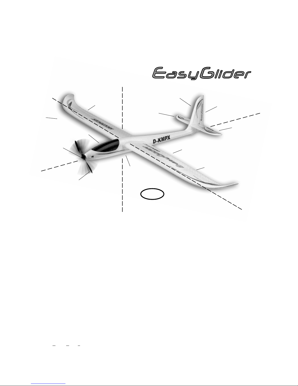
Grundlagen am Beispiel eines Flugmodells
Ein Flugzeug bzw. Flugmodell läßt sich mit den Rudern um folgende 3-Achsen steuern - Hochachse, Querachse und Längsachse.
Die Betätigung des Höhenruders ergibt eine Veränderung der Fluglage um die Querachse. Bei Seitenruderausschlag dreht das
Modell um die Hochachse. Wird Querruder gesteuert, so rollt das Modell um die Längsachse. Je nach äusseren Einflüssen wie z.B.
Turbulenzen, die das Modell aus der Flugbahn bringen, muß der Pilot das Modell so steuern, dass es dort hinfliegt, wo er es haben
will. Mit Hilfe des Antriebs (Motor und Luftschraube) wird die Flughöhe gewählt. Die Drehzahl des Motors wird dabei meist von
einem Regler stufenlos verstellt. Wichtig ist, dass alleiniges Ziehen am Höhenruder das Modell nur solange steigen lässt, bis die
Mindestfluggeschwindigkeit erreicht ist. Je nach Stärke des Antriebs sind somit unterschiedliche Steigwinkel möglich.
Das Tragflügelprofil
Rumpf
Kabinenhaube
Tragfläche
(links)
Seitenruder
Höhenruder
Seitenleitwerk
Höhenleitwerk
Tragfläche
(rechts)
Längsachse
Querachse
Hochachse
D
Die Tragfläche hat ein gewölbtes Profil an der die Luft im Flug
vorbeiströmt. Die Luft oberhalb der Tragfläche legt gegenüber
der Luft auf der Unterseite in gleicher Zeit eine größere Wegstrecke zurück. Dadurch entsteht auf der Oberseite der Tragfläche ein Unterdruck mit einer Kraft nach oben (Auftrieb) die das
Flugzeug in der Luft hält. Abb. A
Der Schwerpunkt
Um stabile Flugeigenschaften zu erzielen muss Ihr Flugmodell
wie jedes andere Flugzeug auch, an einer bestimmten Stelle im
Gleichgewicht sein. Vor dem Erstflug ist das Einstellen des
richtigen Schwerpunkts unbedingt erforderlich.
Das Maß wird von der Tragflächenvorderkante ( in Rumpfnähe)
angegeben. An dieser Stelle mit den Fingern oder besser mit der
Schwerpunktwaage MPX # 69 3054 unterstützt soll das Modell
waagerecht auspendeln. Abb. B
Wenn der Schwerpunkt noch nicht an der richtigen Stelle liegt
wird dieser durch Verschieben der Einbaukomponenten (z.B.
Antriebsakku) erreicht. Falls dies nicht ausreicht wird die richtige
Menge Trimmgewicht (Blei oder Knetgummi) an der Rumpfspitze oder am Rumpfende befestigt und gesichert. Ist das
Modell schwanzlastig, so wird Trimmgewicht in der Rumpfspitze
befestigt - ist das Modell kopflastig so wird Trimmgewicht am
Rumpfende befestigt.
Die EWD (Einstellwinkeldifferenz) gibt die Differenz in Winkelgrad an, mit dem das Höhenleitwerk zur Tragfläche eingestellt
ist. Durch gewissenhaftes, spaltfreies montieren der Tragfläche
und des Höhenleitwerks am Rumpf wird die EWD exakt eingehalten.
Wenn nun beide Einstellungen (Schwerpunkt und EWD) stimmen, wird es beim Fliegen und insbesondere beim Einfliegen
keine Probleme geben. Abb. C
Ruder und die Ruderausschläge
Sichere und präzise Flugeigenschaften des Modells können nur
erreicht werden, wenn die Ruder leichtgängig, sinngemäß richtig und von der Ausschlaggröße angemessen eingestellt sind.
Die in der Bauanleitung angegebenen Ruderausschläge wurden bei der Erprobung ermittelt und wir empfehlen die Einstellung zuerst so zu übernehmen. Anpassungen an Ihre Steuergewohnheiten sind später immer noch möglich.
Steuerfunktionen am Sender
Am Fernsteuersender gibt es zwei Steuerknüppel, die bei Betätigung die Servos und somit die Ruder am Modell bewegen.
Die Zuordnung der Funktionen sind nach Mode A angegeben es sind auch andere Zuordnungen möglich.
Folgende Ruder sind mit dem Sender zu bedienen.
Das Seitenruder (links / rechts) Abb. D
Das Höhenruder (hoch / tief) Abb. E
Das Querruder (links / rechts) Abb. F
Die Motordrossel (Motor aus / ein) Abb. G
Der Knüppel der Motordrossel darf nicht selbsttätig in Neutrallage zurückstellen Er ist über den gesamten Knüppelweg rastbar. Wie die Einstellung fünktioniert lesen Sie bitte in der Bedienungsanleitung der Fernsteuerung nach.
Spinner
Querruder
(links)
Querruder
(rechts)
KlappLuftschraube
Page 10
10
Stückliste
BK EasyGliderPRO + electric BlueEdition
Lfd.Stück Bezeichnung Material Abmessungen
1 1 Bauanleitung Papier DIN-A4
2 1 Dekorbogen bedruckte Klebefolie Fertigteil
3 1 Rumpfhälfte links Elapor geschäumt Fertigteil
4 1 Rumpfhälfte rechts Elapor geschäumt Fertigteil
5 1 Rumpfnase Segler EPP geschäumt Fertigteil
7 1 Kabinenhaube Elapor geschäumt Fertigteil
8 1 Tragfläche links Elapor geschäumt Fertigteil
9 1 Tragfläche rechts Elapor geschäumt Fertigteil
10 1 Holmabdeckung links Elapor geschäumt Fertigteil
1 1 1 Holmabdeckung rechts Elapor geschäumt Fertigteil
12 1 Höhenleitwerk Elapor geschäumt Fertigteil
13 1 Seitenleitwerk Elapor geschäumt Fertigteil
Kleinteilesatz
20 2 Klettband Pilzkopf Kunststoff 25 x 60 mm
21 2 Klettband Velours Kunststoff 25 x 60 mm
22 2 Canopy-Lock Verschlussklammer Kunststoff gespritzt Fertigteil
23 2 Canopy-Lock Verschlusszap fen Kunststoff gespritzt Fertigteil
24 4 Einkleberuderhorn Kunststoff gespritzt Fertigteil
25 4 Gestängeanschluß Metall Fertigteil Ø 6mm
26 4 U-Scheibe Metall M2
27 4 Mutter Metall M2
28 4 Inbus-Gewindestift Metall M3 x 3mm
29 1 Inbusschlüssel Metall SW 1,5
30 2 Querrudergestänge m.Z. MetallØ 1 x 80mm
31 1 Scharnier Kunststoff gespritzt Fertigteil
32 1 Hochstarthaken / Glider Kunststoff gespritzt Fertigteil
33 2 Ausgleichsgewicht / Electric St ahl Kugel Ø13mm
34 1 Motorträger Kunststoff gespritzt Fertigteil
35 1 Kabinengriff Kunststoff gespritzt Fertigteil
36 2 Kabelhalter Kunststoff gespritzt Fertigteil
37 2 Rumpflängsspant Kunststoff gespritzt Fertigteil
Drahtsatz
40 1 Holmverbinder GFK-Rohr Ø 10 x 8 x 1000mm
41 1 Stahldraht für HR m.Z. Metall Ø 0,8 x 875mm
42 1 Stahldraht für SR m.Z. Metall Ø 0,8 x 875mm
43 1 Bowdenzugaussenrohr HR Kunststoff Ø 3/2 x 785mm
44 1 Bowdenzugaussenrohr SR Kunststoff Ø 3/2 x 785mm
45 1 Bowdenzuginnenrohr HR Kunststoff Ø 2/1 x 850mm
46 1 Bowdenzuginnenrohr SR Kunst stoff Ø 2/1 x 850mm
47 1 Bowdenzugaussenrohr Antenne Kunststoff Ø 3/2 x 785mm
Ersatzteile (siehe auch Seite 50 / 51 ; bitte bei Ihrem Fachhändler bestellen)
Dekorbogen 72 4236
Dekorbogen electric BlueEdition 72 4239
Rumpfhälften + Bowdenzüge 22 4150
Kabinenhaube 22 4151
Tragflächen 22 4159
Kleinteilesatz 22 4152
Holmverbinder 72 3190
Canopy-Lock (Kabinenhaubenverschluss) 72 5136
Leitwerkssatz 22 4160
D
Page 11

11
EasyGlider PRO + electric BlueEdition
Examine your kit carefully!
MULTIPLEX model kits are subject to constant quality checks throughout the production process, and we sincerely hope that you are
completely satisfied with the contents of your kit. However , we would ask you to check all the parts (referring to the Parts List) before
you start construction, as we cannot exchange components which you have already worked on. If you find any part is not
acceptable for any reason, we will gladly correct the defect or replace the item in question once we have inspected it. Please send the
part to our Model Department, being sure to include the purchase receipt and a brief description of the fault.
We are constantly working on improving our models, and for this reason we must reserve the right to change the kit contents in terms
of shape or dimensions of parts, technology, materials and fittings, without prior notification. Please understand that we cannot
entertain claims against us if the kit contents do not agree in every respect with the instructions and the illustrations.
Caution!
Radio-controlled models, and especially model aircraft, are by no means playthings. Building and operating them safely
requires a certain level of technical competence and manual skill, together with discipline and a responsible attitude at the
flying field. Errors and carelessness in building and flying the model can result in serious personal injury and damage to
property. Since we, as manufacturers, have no control over the construction, maintenance and operation of our products, we
are obliged to take this opportunity to point out these hazards and to emphasise your personal responsibility.
Additional items required for the EasyGlider PRO:
Adhesive:
Use medium-viscosity cyano-acrylate glue (“cyano” - not styrofoam cyano) Zacki ELAPOR # 85 2727 for this model.
Epoxy adhesives produce what initially appears to be a sound joint, but the bond is only superficial, and the hard resin breaks away
from the parts under load. Hot-melt glue (from a glue gun) is a useful alternative adhesive.
MULTIPLEX radio control system components for EasyGlider PRO:
RX-5 light M-Link receiver Order No. 5 5808
or RX-5 M-Link receiver (telemetriy capable) Order No. 5 5817
Tiny-S servo (2x required) Elevator / rudder Order No. 6 5121
Nano-S servo (2x required) aileron Order No. 6 5120
or Tuning-servo Tiny-MG (2x required) Elevator / rudder Order No. 6 5122
Tuning-servo Nano-PRO MG (2x required) aileron Order No. 6 5119
Extension lead 400 mm UNI (2x required) Aileron servo Order No. 8 5029
Extension lead 300 mm UNI (2x required) Aileron servo Order No. 8 5031
Battery charger:
MULTIcharger L-703 EQU 230V Order No. 9 2523
or Combo MULTIcharger LN-3008 EQU w. mains PSU, AC/DC 230V/12V 5,0A Order No. 9 2545
EasyGlider PRO power set
Power set "EasyGlider PRO 3S STANDARD" Li-BATT powered Order No. 33 3651
Power set "EasyGlider PRO 3S STANDARD" Order No. 33 2651
EasyGlider PRO tuning power set
Power set "EasyGlider PRO 3S TUNING" Li-BATT powered Order No. 33 3650
Power set "EasyGlider PRO 3S TUNING" Order No. 33 2650
Flight battery
Li-BATT eco 3/1-2000 (M6) 2000 mAh Order No. 15 7231
Li-BATT eco 3/1-3000 (M6) 3000 mAh Order No. 15 7236
Additional items required for the glider variant only
NiMH receiver battery, 4 / 2100 mAh Order No. 15 6052
Mini switch harness with charge socket Order No. 8 5045
Aero-tow release Order No. 72 3470
Tools:
Scissors, balsa knife, side-cutters.
Note: remove the illustration pages from the centre of the building instructions.
Specification: Glider Electric glider
Wingspan 1800 mm 1800 mm
Overall length 1130 mm 1130 mm
All-up weight approx. 800 g with standard power system approx. 980 g
Wing area, FAI approx. 41.6 dm² FAI approx. 41.6 dm²
Wing loading approx. 20 g / dm² approx. 24 g / dm²
RC functions Elevator, rudder, aileron as glider, plus throttle
GB
Page 12
12
Important note
This model is not made of styrofoam™, and it is not
possible to glue the material using white glue or epoxy.
Please be sure to use cyano-acrylate glue exclusively,
preferably in conjunction with cyano activator (”kicker”).
We recommend medium-viscosity (thick) cyano. This is the
procedure with Elapor®: spray cyano activator on one face
of the joint; allow it to air-dry for around two minutes until
the surface appears to be “dry”, then apply cyano adhesive
to the other face. Join the parts, and immediately position
them accurately .
Please take care when handling cyano-acrylate adhesives.
These materials harden in seconds, so don’t get them on
your fingers or other parts of the body. We strongly
recommend the use of goggles to protect your eyes.
Keep the adhesive out of the reach of children!
1. Before starting construction
Please check the contents of your kit before you start
construction. You will find Figs. 1 + 2 and the Parts List helpful
here.
Completing the fuselage and tail panels
2. Preparing the “snakes”
Check the length of the elevator snake sleeves 43 and 45, and
shorten them if necessary.
43 3 / 2 Ø x 785 mm
45 2 / 1 Ø x 850 mm
Steel 41 0.8 Ø x 875 mm, insert!
Repeat the procedure with the rudder snake sleeves 44 and
46.
44 3 / 2 Ø x 785 mm
46 2 / 1 Ø x 850 mm
Steel 42 0.8 Ø x 875 mm, insert!
Aerial sleeve 47 3/2 Ø x 785 mm (shorten if
necessary)
3. Installing the snakes in the fuselage shells
Important: the fuselage tail boom is considerably strengthened
and stiffened by the addition of the snake outer sleeves 43 and
44, which must be glued full-length to the shells in order to
obtain the full effect. The same applies to the aerial sleeve 47.
Check that the snakes operate smoothly and freely, and take
care not to allow glue to run into the outer sleeves.
Left-hand fuselage shell:
Install the complete elevator snake (wire rod length = 875 mm)
in the left-hand fuselage shell; the pre-formed end should be at
the front (servo end).
Fig. 3
Position the snake outer sleeve 43 flush at the front of the
fuselage shell, as shown in Fig. 4. Lay the shell down flat and
run cyano along the whole length of the outer sleeve 43 and
the channel in the fuselage to glue the parts together strongly.
Fig. 5
Right-hand fuselage shell:
Install the complete rudder snake (wire rod length = 875mm) in
the right-hand fuselage shell. The pre-formed end should be at
the front (servo end).
Fig. 6
Position the snake outer sleeve 44 flush at the front of the
fuselage shell, as shown in Fig. 7. Lay the shell down flat (note
the locating spigot; place the fuselage shell over the corner of
the table) and run cyano along the whole length of the outer
sleeve 44 and the channel in the fuselage to glue the parts
together strongly.
Fig. 8
4. Installing the aerial sleeve
Trial-fit the aerial sleeve 47, cut it to length and glue it in the
right-hand fuselage shell - taking care not to bend or distort the
moulding.
Fig. 9
5. Installing the tow-hook
Glider version: glue the towhook 32 in the moulded recess in
the fuselage shell 4.
Fig. 9
6. Installing the motor mount
Glue the motor mount 34 in the right-hand fuselage shell, and
wipe away any adhesive which is squeezed out. The exposed
face of the motor mount will later be glued when the shells are
joined; take care to keep adhesive off this area. Note that the
motor mount should also be installed in the glider version, as it
adds considerable strength.
Fig. 10
7. Installing the servos in the fuselage shells
Set the servos to “neutral” (centre) from the transmitter, and fit
them in the moulded recesses in the left and right fuselage
shells, as shown in Fig. 11 . If you are using different servos,
you may have to trim the recesses slightly to obtain a close fit.
Lay the servo leads in the channel, running from bottom to top,
and tape them in place. Apply a drop of cyano to the servo lugs to
attach them to the foam material. Connect the pre-formed ends
of the wire pushrods to the servo output arms, and push the arms
onto the servos at an angle of 90° to the servo sides (don’t forget
to fit the servo output screws). Glue the plastic latch catches 22
in both fuselage sides as shown. Glue the extension leads in the
cable holders 36, positioning the ends flush as shown in the detail drawing. Glue the cable holders 36 in the moulded recesses
in both fuselage sides, pushing them in as far as they will go.
Deploy the leads carefully and glue the fore-and-aft formers 37 in
place.
Fig. 11
8. Joining the fuselage shells
The most suitable adhesive for this stage is thick cyano-acrylate,
used in conjunction with activator.
Caution: for the tuning version the balance weights 2 x 33 should
first be glued in the recesses at the tail, as shown in Fig. 12.
The first step is to check “dry” (no glue) that the fuselage shells 3
+ 4 fit together accurately; it may be necessary to carry out minor
trimming.
Spray cyano activator on the joint surfaces of the fuselage shell 4
and leave it to air-dry for about two minutes.
Apply cyano adhesive to the joint surfaces of the fuselage shell
3, then join the parts carefully , taking care to align them accurately
and immediately. Note that the fuselage joint line must be perfectly
straight - no bends allowed!
Fig. 12
9. Installing the rudder hinge
Glue the rudder hinge 31 in the tail end of the fuselage using a
small amount of cyano. Take great care that no glue gets onto the
hinge pivot axis.
Fig. 13
Use a sharp balsa knife to cut a central slot for the rudder hinge
31 in the leading edge of the rudder. Take care: injury hazard!
Extend the slot in the rudder 5 downward by about 3 to 4 mm, as
Page 13

13
this makes it easier to install the rudder and tailplane at a later
stage.
Fig. 14
10. Attaching the horn to the rudder
Use a pair of side-cutters to cut down the projecting spigot of the
rudder horn 24 to a length of about 2 mm. Insert the swivel pushrod
connector 25 in the second hole from the inside of the rudder
horn 24, and secure it with the washer 26 and nut 27. Caution:
note the orientation of the swivel connector! Tighten the nut very
carefully so that the barrel swivels smoothly: it should not wobble,
but must not jam. Apply a tiny drop of cyano to the nut (on the tip
of a pin) when you are satisfied. Fit the grubscrew 28 in the
threaded hole in the swivel pushrod connector 25 using the allen
key 29 provided. Apply cyano activator to the moulded recess in
the rudder, then glue the rudder horn 24 in the recess, with the
row of holes facing the hinge pivot axis.
Fig. 15
11. Freeing the elevator and rudder
Cut a 1 mm slot at each end of the elevator, which is attached to
the tailplane 12. Move the rudder and elevator to and fro repeatedly
in order to make the hinges free-moving - do not separate the
control surfaces!
Fig. 16
12. Attaching the horn to the elevator
Insert the swivel pushrod connector 25 in the outermost hole in
the elevator horn 24, and secure it with the washer 26 and the nut
27. Caution: note the orientation of the swivel connector! T ighten
the nut very carefully so that the barrel swivels smoothly: it should
not wobble, but must not jam. Apply a tiny drop of cyano to the
nut (on the tip of a pin) when you are satisfied. Fit the grubscrew
28 in the threaded hole in the swivel pushrod connector 25 using
the allen key 29 provided.
Apply cyano activator to the moulded recess in the elevator, then
glue the horn 24 in the recess, with the row of holes facing the
hinge pivot axis.
Fig. 17
13. Gluing the fin to the tailplane
Glue the fin 13 to the tailplane 12, setting it exactly at 90°.
Check this with a tool such as a setsquare.
Fig. 18
14. Gluing the tail assembly to the fuselage
Position the tail assembly on the fuselage “dry” (no glue), and
check that the parts fit correctly: first insert the hinge 31 in the
rudder 13, then slide the assembly forward onto the fuselage.
Check in particular that the tailplane 12 is a snug fit on the fuselage,
without any gaps, and lies parallel to the wing saddle at the front
of the fuselage. Y ou can check this by laying the GRP wing joiner
40 on the wing saddle, fixing it in place exactly at right-angles to
the fuselage centreline using paper masking tape. Now sight along
the fuselage from the nose, and align the tailplane with the wing
joiner. When you are confident that the parts can be positioned
correctly, the tail assembly can be glued to the fuselage
permanently. Check once more for correct alignment and a close
fit before leaving the glue to harden. A little extra care at this stage
is well worthwhile, as it avoids long-term disappointment in a model
which refuses to fly straight.
15. Securing the rudder and elevator pushrods
Slip the wire pushrods 41 and 42 through the swivel pushrod
connectors 25, set the servos and control surfaces to neutral
(centre), and tighten the socket-head grubscrews 28 in the
connectors to secure the pushrods.
Figs. 19 + 20
Completing the wings
16. Freeing the ailerons
Cut a 1 mm slot at each end of the ailerons, which are attached to
the wing panels 8 and 9. Move the ailerons to and fro repeatedly
in order to make the hinges free-moving - do not separate the
control surfaces!
Fig. 21
17. Attaching the horns to the ailerons
Insert the swivel pushrod connectors 25 in the outermost holes in
the aileron horns 24, and secure them with the washers 26 and
the nuts 27.
Caution: be sure to produce a handed pair (different lef t and right)!
Tighten the nuts very carefully so that the barrels swivel smoothly:
they should not wobble, but must not jam. Apply a tiny drop of
cyano to the nuts (on the tip of a pin) when you are satisfied. Fit
the grubscrews 28 in the threaded holes in the swivel pushrod
connectors 25 using the allen key 29 provided.
Apply cyano activator to the moulded recesses in the ailerons,
then glue the horns 24 in the recesses, with the row of holes
facing the hinge pivot axis.
Fig. 22
18. Installing the aileron servos
Set the servos to “neutral” (centre) from the transmitter, and fit
the output arms on the servos at 90° to the case sides - 1 x left
and 1 x right (mirror-image pair).
Trial-fit the servos in the moulded recesses in the wing panels 8
and 9: you may need to carry out minor adjustments to suit the
type of servo you are using. Apply a drop of hot-melt glue to each
slot in the wings for the servo mounting lugs, and immediately
press the servos into the recesses; apply an extra drop of glue if
necessary.
Fig. 23
19. Installing the aileron pushrods
Connect the pre-formed end of the steel pushrods 30 to the
outermost hole in the servo output arms, and slip the plain end
through the swivel pushrod connectors 25. Set the ailerons and
servos to neutral, and tighten the grubscrews 28 to secure the
pushrods.
Fig. 23
20. Deploying the aileron servo leads
Lay each servo lead in a curve running towards the wing joiner
channel, and extend it with a 400 mm extension lead: the leads
can either be soldered together or connected using the standard
plug and socket. You will find a notch in each of the spar covers
10 and 11 designed to accommodate the connectors. Now deploy
the extension leads in a straight line along the front face of the
spar channel, standing on edge.
The servo leads must project from the underside of the wing roots
by 60 mm on the left and 75 mm on the right, as this makes it
possible to connect them to the extension leads glued in the cable
holders 36. The remainder of the extension leads can be stowed
in the channel and secured.
Figs. 23 + 24
21. Installing the spar covers
Carefully trial-fit the spar covers 10 and 11 in the wing panels 8
and 9. When you are confident that the covers are a close fit, and
can be installed flush with the wing surface, they can be glued in
place permanently using cyano. Ensure in particular that no
adhesive gets onto those surfaces of the wings into which the
GRP wing joiner 40 will be inserted later. Please don’t fit the wing
joiner 40 in the wings until you are certain that there is no active
adhesive inside the channels. The best way to ensure this is to
spray activator inside and wait for about five minutes. If you neglect
this warning, you may find that you can never separate the wing
panels again.
Page 14

14
Deploy the servo leads in the channel in the spar covers, and
secure them with a little glue (hot-melt adhesive or contact
cement). Don’t use cyano for this, as it tends to make the cable
insulation brittle.
Fig. 23
22. Checking the wing joiner system
The model can now be assembled using the GRP wing joiner 40:
slide the wing panels onto the joiner until they are 5 cm short of
the fuselage on each side, then connect the plugs on the aileron
extension leads to the sockets installed in the fuselage. Slide the
wings closer to the fuselage, and you will find that the connected
leads help to locate them properly . Finally push the wings into the
fuselage on both sides.
Check that the wing panels 8 and 9 are a snug fit (no gaps) where
they meet the fuselage. If they are excessively tight, carefully
compress the edges of the wing root where they enter the fuselage
recess. Note: the wing panels should not be glued to the
fuselage. This enables you to remove the wings to make the
model easier to transport.
Fig. 25
23. Installing the canopy latch lugs
First glue the canopy former 35 in the underside of the canopy 7,
then push the two latch tongues 23 through the former, and set
them flush. Apply thick cyano to the serrated edges - no activator
in this case! - then insert the latch tongues in the slots in the
canopy. Immediately fit the canopy on the fuselage and allow the
latch tongues to engage in the latch catches 22. Check the position
of the canopy on the fuselage without delay , then wait about one
minute before cautiously re-opening the canopy. Spray activator
on the glued joints between the latch tongues and the canopy
former 35.
Fig. 26
24. General note on the receiving system installation
The remaining airborne equipment can now be installed in the
cabin area. Before you fit the receiver battery permanently it is
important to check the model’s Centre of Gravity (CG); you can
often correct the balance point at this stage by shifting the batteries.
Velcro t ape (hook tape 20 + loop t ape 21) is supplied for securing
the receiving system components, but please note that the
adhesive layer on the tape is not sufficient for this application, so
apply cyano to reinforce the joints.
In both versions of the aeroplane the receiver should be installed
aft of the servos, again using Velcro tape. Thread the aerial wire
(attached to the receiver) into the plastic sleeve 47, which has
already been installed. The easy way to do this is to file a length
of steel rod to a point, then slip it through the sleeve 47 from the
tail end. Push the point into the end of the aerial insulation and
apply a drop of cyano to the joint. You can then pull the aerial
through the sleeve from the tail end.
The model is designed for the installation of an MPX aero-tow
release, # 72 3470; the mechanism is simply glued in the glider
nose 5. A short length of snake outer sleeve runs from the release
unit towards the tow release servo, passing through the centre of
the battery pack as shown. The linkage takes the form of a length
of 1.2 mm Ø steel rod.
Fig. 27
25. Motor + receiving system installation in the electric-
powered version
Our recommended components have been thoroughly tested, and
are well matched to each other.
If you wish to use different units, especially if they take the form of
a more powerful motor , then it is your responsibility to ensure that
the airframe is “up to the job”.
Install the motor and tighten all screws thoroughly. Deploy the
power cables in such a way that they cannot possibly foul any of
the motor’s moving parts. Tape the wires to the fuselage.
Fig. 28
The speed controller can be attached to the fuselage side adjacent
to the receiver, using Velcro tape.
The intended location of the flight battery is the space aft of the
receiver. The battery should be positioned in such a way that little
or no ballast is required to balance the completed model. Secure
the battery with Velcro tape in the usual way.
Now complete all the receiving system connections as described
in the instructions supplied with your radio control system. Check
that all the cables are secured well, but are not under strain or
tension.
Fit the propeller driver on the motor output shaft. Allow about 1
mm clearance between the rear face of the driver and the fuselage.
Attach the propeller blades to the propeller driver , and tighten the
pivot screws fully, but not excessively. The blades must be able
to swing down under their own weight when you hold the model’s
nose up.
Switch the transmitter on, connect the flight battery to the speed
controller, and the controller to the receiver. The controller you
are using must feature a BEC (Battery Eliminator Circuit) system,
i.e. the receiver draws power from the flight battery.
Switch the motor on briefly, and check the direction of rotation of
the propeller. When test-running the power system remove all
light, loose objects behind the model, and hold it really firmly.
Caution: even small motors and propellers represent a
serious injury hazard!
26. Setting the control surface travels
The control surface travels must be correct, otherwise the model
will not respond harmoniously to the controls. All travels are
measured at the widest point of the control surface concerned.
Elevator
up - stick back (towards you) - approx. + 8-10mm
down - stick forward (away from you) - approx. - 8-10mm
Rudder left and right approx.15-20mm
each way
Ailerons
up approx. + 15 mm
down approx. - 6 mm
Spoilers - both ailerons up approx. + 20 mm
Spoiler mixer (elevator trim compensation)
approx. - 4 mm
Fig. 29
The “Spoiler” function is designed to shorten the landing approach
by deflecting both ailerons up simultaneously. At the same time
the appropriate down-elevator trim is mixed in, so that the model
maintains a stable attitude. This function can only be implemented
if your radio control system features suitable mixer facilities.
Please refer to the instructions supplied with your RC system for
details of this.
Note: when you apply a right-aileron command, the right-hand
aileron - as seen from the tail, looking forward - must deflect up.
If you cannot set the stated control surface travels using your
radio control system’s adjustment facilities, you may need to reinstall the swivel pushrod connector in a different hole in the horn.
Page 15
15
27. Gilding the lily - applying the decals
The kit is supplied with a multi-colour decal sheet, part 2. Cut out
the individual name placards and emblems and apply them to the
model in the positions shown in the kit box illustration, or in another
arrangement which you find pleasing.
28. Balancing the model
Like every other aircraft, your EasyGlider PRO must be balanced
at a particular point if it is to fly efficiently and stably. Assemble
the model completely, ready to fly. Corrections are possible by
altering the position of the receiver battery or the flight pack. If
this is still not sufficient, add nose ballast or tail ballast until the
model balances at the stated point.
The Centre of Gravity should be at a point 70 mm back from the
leading edge of the wing, measured where the wings meet the
fuselage. Mark this point on the underside of the wing roots with
a waterproof felt-tip pen. Support the model at the marked points
on two fingertips, and the aeroplane should balance level. Make
any adjustments required, and mark the location of the airborne
components once you have found the correct position in the
fuselage, so that you can be sure always to replace the battery in
the same position.
Fig. 30
29. Preparing for the first flight
For the first flight wait for a day with as little breeze as possible.
The early evening is often a good time.
If this is your first model aircraft, your next step is to ask an
experienced model pilot to help you, as things usually do not go
well if you try to manage on your own. Y our local model flying club
should be able to help you find someone, or - failing that - your
nearest model shop may be able to assist you. Our flight simulator
for the PC can also provide valuable experience prior to your
“first real steps” in model flying.
You can download the simulator at no charge from our website
www.multiplex-rc.de. You will also need the matching interface
cable for your MPX transmitter; this is available from model shops
under Order No. # 8 5153.Be sure to carry out a range check
before the first flight.
Just before the flight, charge up the transmitter battery and the
flight pack (or receiver battery) using the recommended
procedures. Ensure that “your” channel is not already in use before
you switch on the transmitter.
Ask your assistant to walk away from the model, holding the
transmitter. The aerial should be fitted but completely collapsed.
Your assistant should operate one of the functions constantly while
you watch the servos. The non-controlled servo should stay
motionless up to a range of about 60 m, and the controlled one
should follow the stick movements smoothly and without any delay .
Please note that this check can only give reliable results if the
radio band is clear of interference, and if no other radio control
transmitters are in use - even on different channels. If the range
check is successful, repeat it with the motor running (EasyGlider
Electric only). There should be no more than a very slight reduction
in effective radio range with the motor turning.
If you are not sure about anything, please don’t risk a flight. Send
the whole system (including battery, switch harness and servos)
to the Service Department of your RC system manufacturer and
ask them to check it.
The first flight ...
Glider:
A test-glide from shoulder level, directly into wind, will give you an
approximate idea of the model’s “trim”, i.e. whether it is set up
correctly, or whether the control surfaces or transmitter trims need
to be adjusted. If the model swings away to one side, move the
rudder trim slightly in the opposite direction. If the model banks one wing lower than the other - apply slight aileron trim correction.
Hand-towing
This is the classic method of launching a glider to height. Att ached
to a suitable length of towline, the model is pulled up by your
assistant running into wind; the glider will rise up the line in a
similar fashion to a kite. The towline first needs to be prepared as
follows: tie the towring and a pennant to the “model” end of the
line. The ring is engaged on the towhook 32, the towline unwound
and your assistant (launcher) takes the free end and walks upwind
until the line is taut. The model should be held under gentle tension
before it is released. The launcher watches the model (over his
shoulder), adjusting his pace to maintain a steady rate of climb.
Take care not to overstress the model during the launch; this is a
particular danger in a fairly strong wind.
Bungee launching
This is the easiest method of launching a glider of this size, as no
assistant is needed, and launch heights of around 100 m are
easily achieved. From this altitude quite long flying times can be
achieved, and they will be even longer if you manage to contact a
thermal, although this does depend on the prevailing weather.
Thermal flying
Making the best use of flat field thermals is not particularly easy,
and calls for considerable skill and experience. Areas of rising air
are harder to detect and recognise at a flat field, because they
tend to occur at higher altitude than at the hillside, where it is
often possible to find lift while the model is cruising along the
edge of the slope and then circle away in it. A thermal at a flat
field which occurs directly overhead is very hard to recognise,
and to exploit it to the full requires a highly skilled pilot. For this
reason it is always best to go thermal seeking off to one side of
where you are standing.
You will recognise thermal cont act by the glider’s behaviour. Good
thermals are obvious because the model will climb strongly, but
weak thermals take a practised eye to detect, and you will need a
lot of skill to make use of them. With a little practice you will be
able to recognise likely trigger points for thermals in the local
landscape. The ground warms up in the sun’s heat, but heat
absorption varies according to the type of terrain and the angle of
the sun’s rays. The air over the warmer ground becomes warmer
in turn, and the mass of warm air flows along close to the ground,
driven by the breeze. Strong winds usually prevent thermal buildup. Any obstruction - a shrub or tree, a fence, the edge of a wood,
a hill, a passing car, even your own model on the landing approach
- may cause this warm air to leave the ground and rise. Imagine a
drop of water on the ceiling, wandering around aimlessly, and
initially staying stuck to the ceiling. If it strikes an obstruction it will
fall on your head. A triggered thermal can be thought of as the
opposite of the drop of water.
The most obvious thermal triggers include sharply defined snow
fields on mountain slopes. The air above the snow field is cooled,
and flows downhill; at the edge of the snow field, part-way down
the valley, the cool air meets warm air flowing gently uphill, and
pushes it up and away as if cut off by a knife. The result is an
extremely powerful but bumpy thermal bubble. Your task is to
locate the rising warm air and centre your model in it. You will
need to control the glider constantly to keep it centred, as you
can expect the most rapid climb rate in the core of the thermal.
Once again, this technique does demand some skill.
To avoid losing sight of the machine be sure to leave the thermal
in good time. Remember that a glider is always easier to see
under a cloud than against a clear blue sky. If you have to lose
Page 16

16
height in a hurry, do bear the following in mind:
The structural strength of the EasyGlider PRO is very great for
this class of model, but it is not infinite. If you attempt to destroy
the model forcibly, please don’t expect any sympathy or
compensation from us.
Flying at the slope
Ridge soaring is an extremely attractive form of model flying.
Soaring for hours on end in slope lift, without needing any outside
aid for launching, must be one of the finest of modelling
experiences. But to “milk” a thermal to the limits of vision, bring it
down again in a continuous series of aerobatic manoeuvres, and
then repeat the whole show - that must surely be the last word in
model flying.
But take care - there are dangers for your model lurking at the
slope. Firstly , in most cases landing is much more difficult than at
a flat field site. It is usually necessary to land in the lee of the hill
where the air is turbulent; this calls for concentration and a highspeed approach with last-minute airbrake extension. A landing
on the slope face, i.e. right in the slope lift, is even more difficult.
Here the trick is to approach slightly downwind, up the slope, and
flare at exactly the right moment, just before touch-down.
Aero-towing
An ideal combination for learning to aero-tow, and for actual aerotowing, is a Mentor and an EasyGlider PRO. If you wish to takeoff from grass, you will need a fairly powerful motor in the Magister, e.g. a brushless external rotor type (generally known as an
“outrunner”) with around 300 Watts of power.
For the tow you require a 20 m length of braided cable of 1 to 1.5
mm Ø. Tie a loop of 0.5 mm Ø nylon line (weak link) at the end,
and connect it to the aero-tow release (# 72 3470) fitted to the
EasyGlider PRO.
Fig. 27
Check that the towline is resting on top of the Mentor’s tailplane.
The tug now rolls forward until the towline is taut, and only then
should the tug’s pilot apply full-throttle. Both aeroplanes
accelerate: the tug stays on the ground initially, while the glider
lifts off, but the glider pilot keeps his model flying low above the
ground, directly in the wake of the tug; the tug can now lift off
safely. The two models should be kept climbing steadily, even
through turns. Avoid flying directly over your heads during the
first few attempts at aero-towing, as it is difficult to detect the
models’ attitudes from this angle. To drop the tow cease climbing,
bring the two aeroplanes to straight and level flight, then close
the throttle on the tug and operate the tow-release on the glider.
Electric flying
With the electric version - the EasyGlider Electric - you have the
optimum level of autonomy and independence. You can fly from
a flat field and carry out about four climbs to a sensible gliding
height from a single battery charge. At the slope you can also
keep the electric power system as a “lifebelt”, i.e. you only use
the motor to “keep afloat”, and avoid landing out, i.e. landing at
the bottom of the slope when the lift fails.
Flight performance
What is meant by a glider’s performance?
The two most important parameters are sinking speed and glide
angle. Sinking speed is a measure of the vertical height lost per
second relative to the surrounding air. The sinking speed is
primarily determined by the wing loading (weight relative to wing
area). Here the EasyGlider PRO offers a really excellent
performance - much better than conventional models - as its wing
loading is so low (only around 17 g / dm²). This means that only
slight thermal assistance is necessary (warm air rising) to cause
the model to gain height. Wing loading is also the main factor in
determining the model’s airspeed - the lower the loading, the
slower the model. Low airspeed means that the model can be
turned extremely tightly , and this is also advantageous when thermal flying, as areas of lift are usually very small when close to the
ground.
The glider’s low airspeed also benefits you considerably if you
are a beginner, as you have more time to think, and the model is
more likely to “excuse” a mistake at the controls.
However, there’s always a down-side:
The other important parameter in glider performance is the glide
angle. This is stated as a ratio, i.e. from a particular altitude the
model flies such and such a distance. The glide angle increases
as wing loading rises, and at the same time - of course - the
model’s airspeed increases. This becomes necessary if you wish
to fly in relatively strong winds, and when you need “energy
retention” for flying aerobatics.
For thermal flying you need a good glide angle too, as this is the
key to flying across areas of “sink” (the opposite of a thermal)
quickly, so that you can seek out another thermal. To increase
the glide angle you need to increase the wing loading, and this is
done by increasing the glider’s weight, i.e. by installing ballast in
the model. This should be positioned in the wing if possible. In
the EasyGlider PRO there is an ideal location: it is the GRP tube
which forms the wing joiner. The internal diameter of this tube is
7.8 mm. Normally a ballast rod of this size would be difficult to
find, and expensive to purchase. However, by chance the diameter
of standard M8 studding (threaded rod) is just the right size. This
material has a diameter of 7.7 mm, and you will be able to
buy it at low cost in any DIY store. You may find that only half a
full length is sufficient. In this case you must ensure that the rod
cannot slide from side to side, e.g. by fitting lengths of balsa dowel
in both ends of the wing joiner, so that the weight is held in the
centre.
Safety
Safety is the First Commandment when flying any model aircraft.
Third party insurance should be considered a basic essential. If
you join a model club suitable cover will usually be available
through the organisation. It is your personal responsibility to ensure
that your insurance is adequate.
Make it your job to keep your models and your radio control system
in perfect order at all times. Check the correct charging procedure
for the batteries used in your RC set. Make use of all sensible
safety measures and precautions which are advised for your
system. An excellent source of practical accessories is the MULTIPLEX main catalogue, as our products are designed and
manufactured exclusively by practising modellers for other
practising modellers.
Always fly with a responsible attitude. You may think that flying
low over other people’s heads is proof of your piloting skill; others
know better. The real expert does not need to prove himself in
such childish ways. Let other pilots know that this is what you
think too. Always fly in such a way that you do not endanger
yourself or others. Bear in mind that even the best RC system in
the world is subject to outside interference. No matter how many
years of accident-free flying you have under your belt, you have
no idea what will happen in the next minute.
The fascination of it all
Model flying is, and always has been, a fascinating hobby , and a
thoroughly enjoyable way of spending your leisure hours. Take
your time to get to know your new EasyGlider PRO really well.
Plan to spend many hours in the open air, where you will learn to
appreciate the model’s excellent performance and its docile
handling. You can join us in enjoying one of the few types of sport
which combine high technology, manual dexterity, and
sophisticated personal skills. You can fly alone or with friends,
and at the same time you can enjoy the pleasures of nature treats which have become rare in today’s world.
Page 17

17
We - the MUL TIPLEX team - wish you many hours of pleasure in
building and flying your new model. Happy landings!
MULTIPLEX Modellsport GmbH & Co. KG
Model Development Dept.
Page 18

18
L.H. wing
panel
Elevator
GB
Spinner
Wing section
The wing features a cambered airfoil section over which the air
flows when the model is flying. In a given period of time the air
flowing over the top surface of the wing has to cover a greater
distance than the air flowing under it. This causes a reduction in
pressure on the top surface, which in turn creates a lifting force
which keeps the aircraft in the air. Fig. A
Centre of Gravity (CG)
To achieve stable flying characteristics your model aircraft must
balance at a particular point, just like any other aircraft. It is
absolutely essential to check and set the correct CG position
before flying the model for the first time.
The CG position is stated as a distance which is measured aft
from the wing root leading edge, i.e. close to the fuselage. Support the model at this point on two fingertips (or - better - use the
MPX CG gauge, # 69 3054); the model should now hang level.
Fig. B
If the model does not balance level, the installed components
(e.g. flight battery) can be re-positioned inside the fuselage. If
this is still not sufficient, attach the appropriate quantity of trim
ballast (lead or plasticene) to the fuselage nose or tail and secure
it carefully . If the model is tail-heavy, fix the ballast at the fuselage
nose; if the model is tail-heavy , attach the ballast at the t ail end of
the fuselage.
The longitudinal dihedral is the difference in degrees between
the angle of incidence of the wing and of the tail. Provided that
you work carefully and attach the wing and tailplane to the fuselage
without gaps, the longitudinal dihedral will be correct automatically .
If you are sure that both these settings (CG and longitudinal
dihedral) are correct, you can be confident that there will be no
major problems when you test-fly the model. Fig. C
Control surfaces, control surface travels
The model will only fly safely , reliably and accurately if the control
surfaces move freely and smoothly, follow the stick movements
in the correct “sense”, and move to the stated maximum travels.
The travels stated in these instructions have been established
during the test-flying programme, and we strongly recommend
that you keep to them initially. You can always adjust them to
meet your personal preferences later on.
Transmitter controls
The transmitter features two main sticks which the pilot moves to
control the servos in the model, which in turn operate the control
surfaces.
The functions are assigned according to Mode A, although other
stick modes are possible.
The transmitter controls the control surfaces as follows:
Rudder (left / right) Fig. D
Elevator (up / down) Fig. E
Aileron (left / right) Fig. F
Throttle (motor off / on) Fig. G
Unlike the other controls, the throttle stick must not return to the
neutral position automatically . Instead it features a ratchet so that
it stays wherever you put it. Please read the instructions supplied
with your radio control system for the method of setting up and
adjusting the transmitter and receiving system.
Basic information relating to model aircraft
Any aircraft, whether full-size or model, can be controlled around the three primary axes: vertical (yaw), lateral (pitch) and longitudinal
(roll).
When you operate the elevator, the model’s attitude alters around the lateral axis. If you apply a rudder command, the model swings
around the vertical axis. If you move the aileron stick, the model rolls around its longitudinal axis. External influences such as air
turbulence may cause the model to deviate from its intended flight path, and when this happens the pilot must control the model in
such a way that it returns to the required direction. The basic method of controlling the model’s height (altitude) is to vary motor speed
(motor and propeller). The rotational speed of the motor is usually altered by means of a speed controller. Applying up-elevator also
causes the model to gain height, but at the same time it loses speed, and this can only be continued until the model reaches its
minimum airspeed and stalls. The maximum climb angle varies according to the power available from the motor.
Fuselage
Canopy
Rudder
L.H.Aileron
Fin
Tailplane
R.H. wing
panel
Longitudinal axis
vertical axis
lateral axis
R.H. Aileron
Page 19
19
Parts List
KIT EasyGlider PRO + electric BlueEdition
Part No. Description Material Dimensions
No. off
1 1 Building instructions Paper DIN A4
2 1 Decal sheet Printed adhesive film 350 x 1000 mm
3 1 L.H. fuselage shell Elapor foam Ready made
4 1 R.H. fuselage shell Elapor foam Ready made
5 1 Glider nose EPP foam Ready made
7 1 Canopy Elapor foam Ready made
8 1 L.H. wing panel Elapor foam Ready made
9 1 R.H. wing panel Elapor foam Ready made
10 1 L.H. spar cover Elapor foam Ready made
11 1 R.H. spar cover Elapor foam Ready made
12 1 Tailplane Elapor foam Ready made
13 1 Fin Elapor foam Ready made
Small parts set
20 2 Velcro tape, hook Plastic 25 x 60 mm
21 2 Velcro tape, loop Plastic 25 x 60 mm
22 2 Canopy-Lock catch Inj. moulded plastic Ready made
23 2 Canopy-Lock tongue Inj. moulded plastic Ready made
24 4 Glue-fitting control surface horn Inj. moulded plastic Ready made
25 4 Swivel pushrod connector Metal Ready made, 6 mm Ø
26 4 Washer Metal M2
27 4 Nut Metal M2
28 4 Allen-head grubscrew Metal M3 x 3 mm
29 1 Allen key Metal 1.5 A/F
30 2 Pre-formed aileron pushrod Metal 1 Ø x 80 mm
31 1 Hinge Inj. moulded plastic Ready made
32 1 Glider towhook Inj. moulded plastic Ready made
33 2 Trim ballast, tuning version Steel ball 13 mm Ø
34 1 Motor mount Inj. moulded plastic Ready made
35 1 Canopy former Inj. moulded plastic Ready made
36 2 Cable holder Inj. moulded plastic Ready made
37 2 Fuselage fore-and-aft former Inj. moulded plastic Ready made
Wire and rod set
40 1 Wing joiner GRP tube 10 Ø x 8 x 1000 mm
41 1 Pre-formed elevator pushrod Metal 0.8 Ø x 875 mm
42 1 Pre-formed rudder pushrod Metal 0.8 Ø x 875 mm
43 1 Elevator snake outer sleeve Plastic 3 / 2 Ø x 785 mm
44 1 Rudder snake outer sleeve Plastic 3 / 2 Ø x 785 mm
45 1 Elevator snake inner tube Plastic 2 / 1 Ø x 850 mm
46 1 Rudder snake inner tube Plastic 2 / 1 Ø x 850 mm
47 1 Aerial sleeve Plastic 3 / 2 Ø x 785 mm
Replacement parts (see also page 50/51; please order from your local model shop)
Decal sheet 72 4236
Decal sheet electric BlueEdition 72 4239
Fuselage shells + snakes 22 4150
Canopy 22 4151
Wing panels 22 4159
Small parts set 22 4152
Wing joiner 72 3190
Canopy-Lock (canopy retainer) 72 5136
Tail set 22 4160
GB
Page 20

20
EasyGlider PRO + electric BlueEdition
Familiarisez-vous avec le kit d’assemblage!
Les kits d’assemblages MULTIPLEX sont soumis pendant la production à des contrôles réguliers du matériel. Nous espérons que le
contenu du kit répond à vos espérances. Nous vous prions de vérifier le contenu (suivant la liste des pièces) du kit avant l’assemblage,
car les pièces utilisées ne sont pas échangées. Dans le cas où une pièce ne serait pas conforme, nous sommes disposé à la
rectifier ou à l’échanger après contrôle. Veuillez retourner la pièce à notre unité de production sans omettre de joindre le coupon de
caisse ainsi qu’une petite description du défaut.
Nous essayons toujours de faire progresser technologiquement nos modèles. Nous nous réservons le droit de modifications de la
forme, dimensions, technologie, matériel et contenu sans préavis. De ce fait, nous ne prenons donc pas en compte toutes réclamations
au sujet des images ou de données ne correspondantes pas au contenu du manuel.
Attention!
Les modèles radiocommandés, surtout volants, ne sont pas des jouets au sens propre du terme. Leur assemblage et
utilisation demande des connaissances technologiques, un minimum de dextérité manuelle, de rigueur, de discipline et
de respect de la sécurité. Les erreurs et négligences, lors de la construction ou de l’utilisation, peuvent conduire à des
dégâts corporels ou matériels. Du fait que le producteur du kit n’a plus aucune influence sur l’assemblage, la réparation
et l’utilisation correcte, nous déclinons toute responsabilité concernant ces dangers.
Compléments nécessaires au modèle EasyGlider PRO :
Colle rapide
Utilisez de la colle rapide (cyanoacrylate) Zacki ELAPOR # 85 2727 d’une viscosité moyenne - pas de colle rapide pour polystyrène !
Les colles Epoxy ne donnent qu’un joint de tenue moyenne, car celui-ci casse lorsqu’il subit des charges un peu plus importantes et
les pièces ne tiennent plus. Le joint n’est que superficiel. Comme alternative, vous pouvez utiliser de la colle thermofusible.
Eléments de radiocommande Multiplex pour EasyGlider PRO:
Récepteur RX-5 light M-Link Nr. Com. 5 5808
ou Récepteur RX-5 M-Link (telemetriefähig) Nr. Com. 5 5817
Servo Tiny-S (besoin de 2x) Profondeur/Direction Nr. Com. 6 5121
Servo Nano-S (besoin de 2x) Aileron Nr. Com. 6 5120
ou Tuning-Servo Tiny-MG (besoin de 2x) Profondeur/Direction Nr. Com. 6 5122
Tuning-Servo Nano-PRO MG (besoin de 2x) Aileron Nr. Com. 6 5119
Rallonge de câble 400mm UNi (besoin de 2x) Servo d’aileron Nr. Com. 8 5029
Rallonge de câble 300mm UNI (besoin de 2x) Servo d’aileron Nr. Com. 8 5031
Chargeur
MULTIcharger L-703 EQU 230V Nr. Com. 9 2523
ou Combo MULTIcharger LN-3008 EQU av. transf.,AC/DC 230V/12V 5,0A Nr. Com. 9 2545
Kit de propulsion EasyGlider PRO
Kit de propulsion "EasyGlider PRO 3S STANDARD" Li-BATT powered Nr. Com. 33 3651
Kit de propulsion "EasyGlider PRO 3S STANDARD" Nr. Com. 33 2651
Kit de propulsion tuning EasyGlider PRO
Kit de propulsion "EasyGlider PRO 3S TUNING" Li-BATT powered Nr. Com. 33 3650
Kit de propulsion "EasyGlider PRO 3S TUNING" Nr. Com. 33 2650
Accu de propulsion
Li-BATT eco 3/1-2000 (M6) 2000mAh Nr. Com. 15 7231
Li-BATT eco 3/1-3000 (M6) 3000mAh Nr. Com. 15 7236
Compléments pour la version planeur :
Accu de réception (NiMh) 4 / 2100mAh Nr. Com. 15 6052
Interrupteur Mini avec prise de charge Nr. Com. 8 5045
Crochet de remorquage Nr. Com. 72 3470
Outils :
Ciseaux, cutter, pince coupante
Remarque : Séparer les pages d’images du milieu du fascicule d’instruction !
Données techniques : planeur planeur motorisé
Envergure 1.800 mm 1.800 mm
Longueur totale 1.130 mm 1.130 mm
Poids en vol env. 800 g avec propulsion de série env. 980 g
Surface alaire FAI env. 41,6 dm² FAI env. 41.6 dm²
Charge alaire env. 20 g/dm² env. 24 g/dm²
Fonctions RC Direction, profondeur, ailerons fonction moteur en plus
F
Page 21
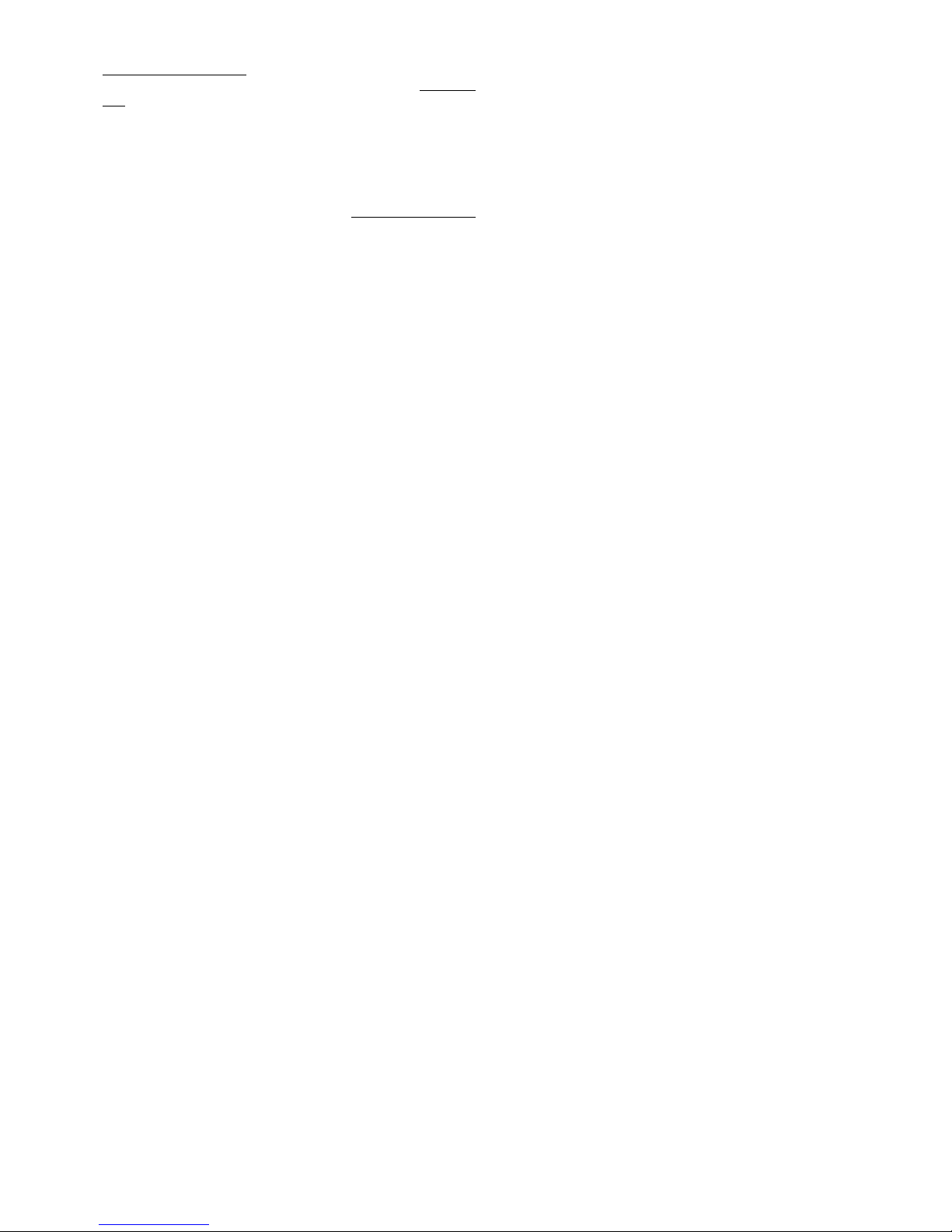
21
Information importante
Ce modèle n’est pas en polystyrène™!De ce fait, n’utilisez
pas de colle blanche ou époxy. N’utilisez que des colles
cyanoacrylate (colle rapide), de préférence avec ajout
d’activateur (Kicker). Pour tous les joints de colle, utilisez
une colle cyanoacrylate avec une viscosité moyenne. Pour
les pièces en Elapor®, vaporisez toujours l’activateur (Kikker) sur une des pièces à coller - laissez aérer pendant 2
minutes, et enduisez l’autre pièce avec de la colle
cyanoacrylate. Assemblez les pièces et amenez-les de suite
en bonne position.
Attention lorsque vous travaillez avec une colle
cyanoacrylate. Celle-ci durcie en l’espace de quelques
secondes, et de ce fait, évitez tout contacte avec les doigts
ou autres parties du corps. Portez des lunettes pour protéger
les yeux! Stockez le produit loin de la portée des enfants!
Ne pas laisser entre les mains des enfants !
1. Avant l’assemblage
Vérifiez le contenu de la boite.
Pour cela, vous pouvez vous aider de l’image Fig.1+2 et de la
liste des pièces.
Assemblage du fuselage et des gouvernes
2. Préparation de la tringlerie
Contrôlez et ajustez si nécessaire la longueur des gaines 43 et
45 pour la tringle commandant la profondeur, et, si nécessaire,
ajustez-la.
43 Ø 3/2 x 785mm
45 Ø 2/1 x 850mm
acier 41 Ø 0,8 x 875mm à emboîter !
Procédez de même avec les gaines 44 et 46 pour la tringle de la
direction
44 Ø 3/2 x 785mm
46 Ø 2/1 x 850mm
acier 42 Ø 0,8 x 875mm à emboîter !
tube d’antenne
47 Ø 3/2 x 785mm (à raccourcir si nécessaire)
3. Mise en place des gaines dans le fuselage
Attention : en collant soigneusement les gaines extérieures de
tringles 43 et 44 sur toute longueur dans le fuselage, ainsi que la
gaine 47 de réception pour l’antenne, vous renforcez sensiblement
la rigidité du fuselage et la stabilité des supports de gouvernes.
Veillez à ce que les gaines intérieures coulissent facilement et
qu’aucune colle ne se mette entre les deux gaines.
Partie gauche du fuselage :
Placez la gaine pour la profondeur munie de sa tringle (longueur
de la corde à piano = 875mm) dans le fuselage en plaçant la
partie en Z vers le servo.
Fig. 3
Positionnez la gaine extérieure 43 dans la moitié du fuselage en
regard avec le bord du fuselage comme indiqué sur la Fig. 4.
Posez cette moitié de fuselage bien à plat et collez y la gaine
extérieure 43 sur toute la longueur de la rainure avec de la colle
rapide
Fig. 5
Partie droite du fuselage :
Placez la gaine pour la direction munie de sa tringle (longueur de
la corde à piano = 875mm) dans le fuselage en plaçant la partie
en Z montrant vers le servo.
Fig. 6
Positionnez la gaine extérieure 44 en regard avec le bord du
fuselage comme indiqué sur la Fig. 7. Posez cette moitié de
fuselage bien à plat (attention aux picots d’arrêts / placez le
fuselage en laissant dépasser une partie par-dessus le bord de
table) et collez y la gaine extérieure 44 sur toute la longueur de la
rainure avec de la colle rapide
Fig. 8
4. Mise en place de la gaine pour l’antenne
Ajustez la longueur puis collez la gaine d’antenne 47 dans la
moitié droite du fuselage – ne tordez pas celui-ci pendant
l’opération !
Fig. 9
5. Mise en place du crochet de remorquage
Pour le modèle en version planeur, collez sur votre modèle le
crochet de remorquage 32 dans la partie prédécoupée de la moitié
de fuselage 4.
Fig. 9
6. Mise en place du support moteur
Collez le support moteur 34 dans la partie droite du fuselage. Il
ne faut pas que la colle dépasse l’autre partie du support afin de
pouvoir assembler soigneusement les deux parties du fuselage.
Pour des raisons de rigidité, le support sera également équipé
sur la version planeur.
Fig. 10
7. Mise en place des servos dans la moitié du fuselage
Placez les servos au neutre à l’aide de votre radiocommande.
Engagez les servos par le côté dans les parties droite et gauche
du fuselage comme indiqué sur la Fig. 11. Si vous utilisez d’autres
servos, il est possible de devoir ajuster les ouvertures.
Placez les câbles de commandes de l’arrière vers l’avant dans
les ouvertures prévues puis fixez les avec du ruban adhésif. Fixez
les servos avec une goûte de colle CA et les languettes avec la
mousse. Engagez le bout en Z de la tringle de commande dans
le palonnier du servo en ayant au préalable placé ce dernier à
90° sur le servo (n’oubliez surtout pas la vis de fixation). Collez
les fixations 22 à gauche et à droite du fuselage. Collez les
rallonges à fleur dans le support de câble 36. Collez le support
36 à gauche et à droite dans leurs logements du fuselage en les
enfonçant complètement. Mettez les câbles en place et collez les
renforts de fuselage 37.
Fig. 11
8. Collage des deux parties du fuselage.
La colle la mieux adaptée pour cette opération est la colle CA
épaisse (colle rapide) avec de l’activateur.
Attention : pour la version tunig n’oubliez pas de coller 2
masselottes 33 de centrage dans le fuselage comme indiqué sur
la Fig. 12.
Testez l’assemblage des deux parties du fuselage 3 + 4 sans
utiliser de colle, et vérifiez le positionnement parfait. Si nécessaire,
effectuez quelques ajustements.
Enduisez la partie 4 du fuselage d’activateur puis laissez aérer
pendant environ 2 minutes.
Sur l’autre moitié de fuselage 3 mettez de la colle aux jointures et
sur le support moteur ! Une fois assemblées, la jointure doit être
droite et le fuselage ne doit pas présenter un effet banane.
Fig. 12
9. Mise en place des charnières pour la direction
Collez la charnière 31 avec un peu de colle rapide à l’arrière du
fuselage. Veillez particulièrement à ne pas mettre de colle dans
la charnière.
Fig. 13
A l’aide d’un cutter , effectuez une entaille au niveau du bord avant
de la dérive pour pouvoir accueillir la charnière 31. Procédez avec
Page 22

22
précaution ! Vous pouvez vous blesser. Rallongez l’entaille de la
dérive 5 de 3 à 4mm vers le bas afin de pouvoir facilement adapter
la position des gouvernes de direction et de profondeur sur le
fuselage.
10. Mise en place les guignols sur la dérive
Raccourcissez (avec une pince coupante) la partie en T du guignol
24 pour la dérive 13 d’environ 2mm. Mettez en place l’élément de
fixation de la tringle 25 dans le deuxième trou du corps du guignol
24, et fixez l’ensemble avec une rondelle 26 et l’écrou 27.
Attention : respecter le sens de montage. Serrez avec délicatesse
l’écrou de fixation en veillant à ce que l’élément rotatif tourne
toujours librement sans être branlant. Ensuite sécurisez
l’ensemble avec une goutte de colle rapide (aiguille). Placez
l’écrou de serrage 28 dans l’élément de fixation 25 à l’aide de la
clé 6 pans 29.
Placez les guignols 24 dans leurs logements, en ayant, au
préalable, enduit ceux-ci d’activateur et en orientant la rangée
de trous sur les guignols vers la zone charnière.
Fig. 14
11. Libérez les gouvernes de profondeur et de dérive
Vous devez libérer les gouvernes de profondeur 12 en entaillant
(rainure d’1mm) les deux extrémités. Rodez les gouvernes de
profondeur et de direction en les bougeant plusieurs fois, mais
surtout ne les découpez pas complètement ! Fig. 16
12. Mise en place des guignols sur la profondeur
Mettez en place l’élément de fixation de la tringle 25 dans le trou
extérieur du corps du guignol 24, et fixez l’ensemble avec une
rondelle 26 et l’écrou 27. Attention : respecter le sens de
montage ! Serrez avec délicatesse l’écrou de fixation et sécurisez
l’ensemble avec une goutte de colle rapide (aiguille). Placez
l’écrou de serrage 28 dans l’élément de fixation 25 à l’aide de la
clé 6 pans 29.
Placez les guignols 24 dans leurs logements, en ayant, au
préalable, enduit ceux-ci d’activateur et en orientant la rangée
de trous sur les guignols vers la zone charnière.
Fig. 17
13. Collage des gouvernes de profondeur et de direction
Collez la dérive 13 sur la profondeur 12 en respectant un angle
de 90° entre les deux. Utilisez p ar exemple une équerre pour
vérifier votre ajustement. Fig. 21
14. Collage des gouvernes sur le fuselage
Effectuez un test d’assemblage de la profondeur et de la direction
sur le fuselage sans utiliser de colle et vérifiez le bon
positionnement de l’ensemble. Pour cela engagez tout d’abord
la charnière 31 dans la dérive 13 et amenez ensuite l’ensemble
en position. V eillez surtout à ce que la profondeur 12 repose sans
failles sur la partie support du fuselage et soit parallèle au support
d’aile à l’avant du fuselage. Pour vous aider, positionnez la clé
d’aile 40 dans son logement (sécurisez le par exemple avec une
bande velcro). Visez à partir du nez du modèle en passant par la
clé d’aile pour ajuster la position de la profondeur. Si les gouvernes
se positionnent correctement sur le fuselage, vous pouvez coller
l’ensemble. Vérifiez encore une fois que qu’il n’y a pas de jour au
niveau des joints ! Si vous n’avez pas bien travaillé lors de la
réalisation de cette étape, vous allez le regretter toute la vie de
votre modèle.
15. Fixation des tringles pour la direction et la profondeur
Passez les tringles en acier 41 et 42 dans l’élément de fixation
25 – positionnez les servos et les gouvernes en position centrale
et fixez l’ensemble en serrant l’écrou à six pans 28
Fig. 19 + 20
Assemblage des ailes
16. libérez les ailerons
Libérez les ailerons sur les deux parties d’aile 8 et 9 en entaillant
(rainure d’1mm) les deux extrémités. Rodez la gouverne en la
bougeant plusieurs fois, mais surtout ne les découpez pas
complètement !
Fig. 21
17. Fixation des tringles d’ailerons
Mettez en place l’élément de fixation de la tringle 25 dans le trou
extérieur du corps du guignol 24. Fixez l’ensemble avec une
rondelle 26 et l’écrou 27.
Attention : 1x à gauche et 1x à droite ! Serrez avec délicatesse
l’écrou de fixation et sécurisez l’ensemble avec une goutte de
colle rapide (aiguille). Placez l’écrou de serrage 28 dans l’élément
de fixation 25 à l’aide de la clé 6 pans 29.
Placez les guignols 24 dans leurs logements, en ayant, au
préalable, enduit ceux-ci d’activateur et en orientant la rangée de
trous sur les guignols vers la zone charnière.
Fig. 22
18. Mise en place du servo d’aileron
Placez le servo au neutre et équipez-le de son palonnier afin que
celui-ci forme un angle de 90° avec le servo – 1x à gauche et 1x
à droite (donc miroité).
Ajustez l’emplacement de réception afin de pouvoir accueillir le
servo sur les ailes 8 et 9. Il sera peut être nécessaire d’effectuer
quelques petites adaptations si vous utilisé d’autres servos que
ceux préconisés. Pour la fixation des servos, mettez de la colle
thermofusible dans l’emplacement de réception au niveau des
languettes de fixation de celui-ci et appliquez directement le servo
– vous pouvez rajouter de la colle par après si nécessaire.
Fig. 23
19. Assemblage des tringles de commande des ailerons
Passez l’extrémité en forme de Z de la tringle 30 dans le trou du
palonnier le plus à l’extérieur et enfilez l’autre côté dans l’élément
de fixation 25. Positionnez le servo et la gouverne en position
centrale et fixez l’ensemble en serrant l’écrou à six pans 28
Fig. 23
20. Passage de câble pour le servo d’aileron
Passez le câble de commande du servo dans la fente prévu à cet
effet en direction de la clé d’aile et connectez celui-ci avec sa
rallonge de 400mm. Vous pouvez souder les câbles ou les relier
par leur connecteur de série. Pour le connecteur, un évidemment
spécial est prévu dans le cache pour clé d’aile 10 et 11.
Positionnez celui-ci dans le prolongement et debout sur ce cache.
Mesuré à partir de la nervure principale, le câble doit dépasser
celle-ci de 60mm du côté gauche et 75mm du côté droit afin de
pouvoir facilement être branchée sur le récepteur par le support
de câble 36 lors du montage et du démontage de l’aile. La longueur
de câble restante peut se loger et être fixée dans la fente de
réception.
Fig. 23+24
21. Collage de cache de clé d’aile
Adaptez soigneusement les clés d’ailes 10 et 1 1 sur les ailes 8 et
9. Lorsque le cache de clé d’aile se place correctement, vous
pouvez coller celui-ci avec de la colle rapide. Veillez surtout à ne
pas mettre de la colle sur la zone qui accueillera par la suite la clé
d’aile 40. N’effectuez un test d’assemblage de la clé d’aile 40
que lorsque vous serez certain que la colle est bien sèche (pour
plus de sécurité, vaporisez un peu d’activateur et attendez 5
minutes). Dans le cas contraire, il est possible que vous ne pourrez
plus jamais redémonter votre modèle.
Placez les câbles de commande des servos dans la fente au
niveau du cache de la clé d’aile puis fixez les avec un peu de
colle (de contact ou à chaud). N’utilisez pas de colle CA à ce
niveau, celle-ci détériore l’isolation
Fig. 23
22. Vérifiez le bon emboîtement de l’aile
Page 23

23
Equipez votre modèle avec la clé d’aile 40. Engagez les ailes
jusqu’à environ 5cm de part et d’autre du fuselage. Passez les
câbles des servos d’ailerons par l’évidemment dans le fuselage.
Lors de la mise en place des ailes, aidez un peu les câbles à
retrouver leur place.
Vérifiez le bon positionnement (sans voir de jour) des ailes 8 et 9
sur le fuselage, si nécessaire, ajustez prudemment en pinçant
délicatement les nez de fixations de l’aile lors de l’emboîtement.
Remarque : les moitiés d’ailes ne sont pas collées au
fuselage. Le modèle peu donc être démonté pour permettre un
transport plus facile.
Fig. 25
23. Collage de la verrière et des tétons de verrouillage
Collez tout d’abord la poignée 35 sous la verrière 7. Placez
temporairement les deux tétons de verrouillage 23 dans la poignée
et positionnez correctement l’ensemble. Appliquez de la colle
rapide épaisse sur les dentelures des tétons – ici sans activateur !
– et les placer dans leur fente respective sur la verrière. Placez la
verrière sur le fuselage et engagez les tétons dans les crochets
22. Ajustez l’ensemble sans perdre de temps. Attendez env. 1
minute puis ouvrez délicatement la verrière. Vaporisez de
l’activateur sur les zones de collage des crochets.
Fig. 26
24. Généralité pour le montage de la radiocommande
Dans la zone de la cabine il ne reste plus qu’à amener les éléments
de la radiocommande. Veillez dès à présent à respecter le centre
de gravité lors du positionnement du récepteur et de l’accu. Vous
pouvez corriger le centre de gravité en déplaçant l’accu.
Pour la fixation de ces éléments, vous trouverez de la bande
adhésive velcro avec une partie crochets et une partie velours 20
+ 21. Du fait que la tenue de la colle sur ce ruban n’est pas
suffisant, renforcez le avec une goûte de colle rapide dans le
fuselage.
Pour les deux types de modèles, le récepteur est fixé avec de
ruban velcro derrière les servos. Engagez l’antenne dans le tube
47 prévus à cet effet. Cela est plus simple en utilisant un fil d’acier
avec une petite pointe passant par l’arrière du tube 47. Piquez
celui-ci dans le bout du fil d’antenne et si nécessaire sécurisez-le
tout avec une goûte de colle rapide afin de ne pas perdre le fil
lors du passage de l’antenne.
Le modèle est prévu pour être équipé d’un crochet de remorquage
de chez Multiplex # 72 3470. Pour cela il faut coller le crochet de
remorquage dans le nez 5 du planeur. Une gaine est placée de la
commande du crochet, en passant à côté du pack d’accu, vers le
servo. La commande est réalisée par une tringle métallique Ø
1,2mm.
Fig. 27
25. Montage de la radiocommande et de la propulsion pour
la version électrique
Le matériel que nous vous conseillons a été testé à maintes
reprises et a donné pleine satisfaction aux différents utilisateurs.
Veillez noter que si vous choisissez d’utiliser d’autre composant
pour la propulsion, c’est vous qui en êtes responsable.
Montez le moteur et fixez le avec les vis fournis. Disposez les
câbles afin qu’ils ne touchent pas les parties mobiles de la
propulsion. Fixez les avec du ruban adhésif.
Fig. 28
Le régulateur est fixé avec du Velcro à côté du récepteur sur la
paroi du fuselage
L’accu de propulsion a de la place dans le compartiment situé
derrière le récepteur. Il est positionné de telle manière à avoir le
moins de ballast à rajouter pour régler la position du centre de
gravité. Fixez l’accu avec du Velcro.
Afin de vérifiez les branchements, connectez tous les composants
électroniques en fonction des indications de la notice et effectuez
un essai. Vérifiez que tous les câbles sont bien libres de toutes
contraintes.
Assemblez l’entraîneur d’hélice. Laissez un espace d’au moins
1mm entre le fuselage et l’entraîneur.
Montez les pales d’hélices sur l’entraîneur. Serrez doucement
mais fermement les vis de fixation des pales, celles-ci doivent
pouvoir se replier par leur propre poids lorsque vous orientez le
nez du modèle vers le haut.
Mettez en marche l’émetteur et branchez l’accu de propulsion de
votre modèle avec le régulateur puis celui-ci avec le récepteur. Il
est nécessaire que votre régulateur soit équipé de la fameuse
fonction BEC (alimentation du système de réception et de
commande par l’accu de propulsion).
Allumez d’une manière brève la propulsion et vérifiez le sens de
rotation de votre moteur (tenez bien votre modèle lors de l’essai
et enlevez tout obstacle).
Attention : même avec de petits moteurs et de petites hélices
le risque de blessure corporel est élevé si vous ne respectez
pas les consignes de sécurités !
26. Réglage du débattement des gouvernes
Pour obtenir un modèle facilement pilotable, il est vital de régler
correctement les débattements des gouvernes. Les valeurs
indiquées sont toujours à mesurer aux endroits le plus loin de la
gouverne.
Gouverne de profondeur
Vers le haut - manche tiré - env. + 8-10mm
Vers le bas - manche poussé - env. - 8-10mm
Gouverne de direction
Vers la gauche et la droite env. 15-20mm
Gouverne d’ailerons
Vers le haut env. +15mm
Vers le bas env. –6mm
Aérofreins- les deux ailerons
vers le haut env. +20mm
Mélange Aérofrein avec
Profondeur env. –4mm
Fig. 29
La distance d’atterrissage peut être réduite en utilisant la fonction
‘’aérofrein’’ qui fera monter les deux gouvernes d’ailerons. En
même temps mélangez à cette fonction un mouvement de la
profondeur afin de garder un modèle stable. Cela est possible à
condition d’avoir une radiocommande permettant une telle fonction
mélangeur.
Pour cela, lisez attentivement la notice de votre radiocommande.
Remarque : dans le sens de vol, lorsque vous mettez le manche
des ailerons à droite, l’aileron droit doit se lever.
Dans le cas ou votre radiocommande ne permet pas une inversion
du sens de débattement, il est nécessaire de d’inverser l’endroit
de fixation de la tringle.
27. Un petit quelque chose pour l’esthétique
Pour cela vous trouverez des décalcomanies couleur 2 dans le
kit. Les différents symboles et écritures sont à découper et placer
comme sur l’exemple (image de la boite) ou comme bon vous
semble.
28. Centre de gravité
Afin d’obtenir un vol stable de l’appareil, il est nécessaire
d’équilibrer votre EasyGlider/PRO, comme n’importe quel autre
Page 24

24
appareil volant, à un point précis. Assemblez votre modèle comme
pour un vol. En bougeant l’accu de réception ou de propulsion,
vous pouvez influer sur celui-ci et donc le déterminer précisément.
Si cela devait s’avérer insuffisant, ajouter du plomb en des endroits
bien précis.
Le centre de gravité se situe à 70mm du bord d’att aque de l’aile,
mesurez et marquez l’emplacement avec un feutre indélébile.
Placez l’avion sur votre doigt au niveau de la marque, laissez
l’avion prendre une position d’équilibre. Par déplacement de l’accu
de réception ou de propulsion, vous pouvez corriger la position
du centre de gravité de l’appareil. Lorsque vous aurez trouvé cette
position, faite un marquage de telle manière à toujours placé l’accu
au même endroit.
Fig. 30
29. Préparatifs pour le premier vol
Il est conseillé d’effectuer le premier vol par une météo sans vent.
Pour cela, les occasions se présentent souvent en soirée.
Si vous n’avez encore d’expériences dans le domaine du modèle
réduit, cherchez une aide expérimentée. Si vous essayez tout
seul, ce sera sûrement un coup dans l’eau. Vous trouverez des
contacts auprès du club de modélisme du coin. Vous pouvez
également demander votre revendeur pour obtenir des adresses.
Une autre aide pour assurer ‘’vos premiers pas’’ serait par exemple
notre simulateur de vol pour PC.
Vous pouvez télécharger gratuitement ce simulateur sur notre
page internet www.multiplex-rc.de. Le câble d’interface est disponible chez votre revendeur (Nr. Com. # 8 5153).
Effectuez obligatoirement un test de portée avant le premier
vol!
Les accus de la radiocommande et de propulsion sont bien
chargés, en respectant la notice. Assurez-vous avant la mise en
route de votre ensemble radio, que le canal est disponible.
Une tierce personne s’éloigne, en faisant bouger au moins une
commande. Pendant ce test, avec l’antenne de l’émetteur est en
position rentrée. Surveillez la réaction de vos servos non utilisés.
Il ne devrait y avoir aucune perturbation jusqu’à une distance
d’env. 60m minimum, ni hésitations ni tremblements. Le servo
concerné doit effectuer sans hésitation les ordres donnés. Ce
test n’est valable que si la bande de fréquence est libre et
qu’aucune autre radiocommande n’émette même sur d’autres
canaux! Le test doit être réitéré avec le moteur en marche.
Qu’une petite diminution de portée est admissible.
Dans le cas d’une incertitude, vous ne devez pas décoller . Envoyer
l’ensemble du matériel de radiocommande (avec accu, servos,
interrupteur) à notre section services et réparation pour effectuer
une vérification.
Premier vol ....
Planeur :
Un premier lancé main en ligne droite du modèle, contre le vent,
donne déjà une bonne impression si celui-ci est bien réglé ou s’il
est nécessaire de donner du trim. Si votre modèle glisse d’un
côté, donnez du trim du côté opposé. Si vous avez directement
une partie de l’aile qui chute, corrigez le trim des ailerons.
Décollage main avec une corde
Une méthode classique pour faire décoller un planeur. Le modèle
est tracté par une tierce personne à l’aide d’une corde adaptée,
un peu comme avec un cerf-volant. Pour cela, engagez le bout
de la corde dans l’anneau de décollage et placez-y également
un fanion de contrôle. L’ensemble est fixé au modèle par le
crochet, déroulez la corde et le ‘’coureur’’ tire la corde et court
vers le vent. Attendez d’avoir une petite tension sur le modèle
avant de le lâcher. Le coureur observe le modèle tout au long de
sa course. Celui-ci doit monter uniformément. Surtout par fort
vent, il est à éviter une traction trop importante sur les ailes du
modèle.
Décollage au sandow
Ce type de décollage est le mieux adapté à cette grandeur de
modèle. Vous n’avez pas besoin d’aide et l’altitude atteignable
est de l’ordre de 100m. A cette altitude vous pouvez espérer
atteindre des temps de vol remarquables. La recherche de
thermique ne devrait pas poser de problèmes en fonction des
conditions météorologiques. Le système de décollage à
élastique le mieux adapté se trouve sous le Nr. Com. 72 3388.
Le vol thermique
L’utilisation des thermiques demande de l’expérience au niveau
du pilotage. Les vents ascendants sur terrain plat – en fonction
de votre altitude – sont plus difficilement identifiables au
comportement de votre modèle que sur un terrain en pente, où
les ‘’barbus’’ se situent plus à la hauteur de vos yeux. Reconnaître
une ascendante directement au-dessus de votre tête et de l’utiliser
n’est réalisable que pour des pilotes chevronnés. Pour cela,
recherché ces ascendants en quadrillant l’espace aérien de la
où vous vous trouvez.
Les vents ascendants ne sont reconnaissables que par rapport
au comportement de votre modèle. Si votre modèle en rencontre
une puissante, il va prendre subitement de l’altitude – alors qu’une
faible ne sera détectable qu’avec un œil expérimenté et tout le
savoir d’un pilote expérimenté. Avec un peu de pratique vous
arriverez à reconnaître la naissance d’une thermique en plaine.
En fonction de la réverbération du terrain, l’air est plus ou moins
chauffée, et glisse, en fonction du vent, plus ou moins près du
sol. Cet air chaud se détache du sol en rencontrant une brindille,
un arbre, une clôture, une lisière de forêt, une petite pente, une
voiture qui passe, ou même par le passage de votre modèle et
prend de l’altitude. Cela est comparable à la goûte d’eau qui glisse
sur une surface, puis, lorsqu’elle rencontre un obstacle se détache
et tombe sur le sol.
Les zones ascendantes sont le mieux délimités par exemple audessus des champs de neiges sur les versants des montagnes.
Au-dessus de cette zone enneigée l’air a refroidi et descend, mais
se réchauffe en rencontrant la partie sans neige ce qui provoque
sont détachement du sol et forme des ascendants relativement
violents et instables. Le but du jeu est de trouver cette ascendance
et de ce placer au ‘’centre’’. Par des corrections de trajectoire, il
faudrait garder le modèle au centre ou les effets sont les plus
marqués. Pour cela il est nécessaire d’avoir de l’expérience.
Quittez la zone ascendante à temps, afin d’éviter d’avoir des
problèmes de visibilité de votre modèle. Rappelez-vous toujours
que le modèle est plus visible sous un nuage que dans le ciel
bleu. Pour perdre de l’altitude, gardez à l’esprit : la solidité de ce
modèle EasyGlider/Electric est très élevé pour sa classe,
néanmoins elle n’est pas infinie. N’attendez pas de souplesses
lors d’essais désespérés de destruction.
Vol de pente
Le vol de pente est une manière de pilotage très attractive. La
possibilité de voler pendant des heures sans être dépendant d’une
tierce personne est un très agréable sentiment de liberté. Le neck
plus ultra est bien sur le vol thermique à partir d’une pente. Lancer
le modèle, chercher les thermiques, les trouver, monter jusqu’à
la zone visuelle, faire redescendre le modèle en vol acrobatique
et recommencer le même jeu est une sensation de plénitude.
Mais attention, le vol de pente cache également quelques dangers
pour le modèle. Dans la majeure partie des cas vous avez
l’atterrissage qui est plus difficile que sur un terrain plat. Il est
souvent nécessaire d’atterrir dans les zones de turbulences de
la pente ce qui nécessite de la concentration une approche risquée
nécessitant une aide extérieure. Un atterrissage dans le vent
ascendant est encore plus difficile et demande une orientation
amont du modèle et un arrondi à un moment précis juste avant
de toucher.
Page 25

25
Remorquage
Il existe un mariage idéal de deux modèles pour apprendre le
pilotage avec un remorqueur, l’EasyGlider PRO associé avec le
Mentor.
Pour le remorquage vous nécessitez d’une corde tressée d’env.
1 à 1,5mm de diamètre et d’une longueur d’env. 20m. Au bout
de celle-ci, fixez une boucle formée d’une corde Nylon de
0,5mm (zone fusible) qui se fixera dans le crochet de
remorquage de votre EasyGlider PRO comme l’indique la
Fig. 27.
Du côté du Mentor, effectuez une boucle à l’autre extrémité de la
corde et engagez la dans le crochet de remorquage. Placez les
deux modèles un derrière l’autre contre le vent. La corde de
remorquage repose sur la profondeur du Magister. Le remorqueur
commence à rouler et tend la corde, seulement maintenant il faut
mettre plein gaz – l’ensemble prend de la vitesse – le remorqueur
reste au sol – le planeur décolle mais reste près du sol – ensuite
seulement le remorqueur décolle à son tour. Une montée régulière
est impérative (même dans les virages !). Evitez, lors des premiers
remorquages, les passages au-dessus de vos têtes. Pour
décrocher, terminez votre ascension – placez le remorqueur
et le planeur en position horizontale – réduisez les gaz et
décrochez le planeur.
Vol électrique
Avec la version électrique de votre EasyGlider PRO, vous avez
atteint le plus haut niveau d’indépendance. En plaine, vous pouvez
espérer réaliser env. 8 montées en atteignant une altitude
raisonnable avec une charge d’accu. Sur une pente, vous pouvez
également éviter de couler (couler signifiant un atterrissage plus
bas sur le versant si vous ne trouvez pas d’ascendance).
Performances de vol
Que signifie une performance pour les planeurs ?
Le paramètre le plus important est la finesse et l’angle de glisse.
On comprend par finesse le taux de chute par seconde pour l’air
environnant. Celle-ci est déterminée en première ligne par la
charge alaire (poids/surface portante). L’EasyGlider PRO présente
d’excellentes performances à ce niveau, de loin meilleur que les
modèles standards (seulement env. 17g/dm2). De ce fait, ce
modèle ne nécessite que peu d’ascendance (thermiques) pour
prendre de l’altitude. A cela se rajoute la vitesse de vol
principalement déterminé par la charge alaire (plus celle-ci est
faible et plus le planeur peut voler lentement). Cela vous permet
également de prendre des virages serrés – c’est un avantage
certain lors de vol thermique (près du sol, celle-ci est très serrée).
De plus, cette vitesse faible permet aux débutants de mieux
maîtriser leur modèle. Celui-ci à plus de temps pour réfléchir et le
modèle ‘’pardonne’’ de petites erreurs de pilotage.
Néanmoins : ‘’la où il y a de la lumière, il y a de l’ombre !’’
L’autre paramètre vital est l’angle de glisse. Il est déterminé en
mesurant la distance parcourue par le modèle en fonction de son
altitude de départ. L’angle de glisse augmente si votre charge
alaire augmente ainsi que la vitesse de vol. Cela est nécessaire
si vous devez voler par vent fort ou si vous devez effectuer des
passages pour réaliser des figures acrobatiques.
Egalement pour le vol thermique vous avez besoin de cet angle
de glisse. Vous aurez sûrement des courants d’air descendants
à traverser pour en trouver des ascendants. Pour augmenter votre
charge alaire, vous aurez besoin de ballast. Celui-ci devra être
placé dans les ailes du modèle. Cet emplacement est idéal pour
votre EasyGlider PRO. C’est le tube en fibre de verre dans votre
aile. Le diamètre intérieur de celui-ci est de 7,8mm. En temps
normal, il est assez compliqué de trouver du ballast de ce diamètre
ou très cher. Mais, p ar hasard, la tige à fileter que vous trouvez
dans n’importe quel magasin de bricolage a un diamètre Ø
7,7mm. Dans certain cas vous n’avez besoin que de la moitié de
la tige. Il est à ce moment la nécessaire de caler celle-ci pour
éviter qu’elle ne se déplace (par exemple, enfiler le ballast des
deux côtés pour équilibrer le poids et fixer l’ensemble).
Sécurité
Sécurité est un maître mot dans le monde de l’aéromodélisme.
Une assurance est obligatoire. Dans le cas où vous êtes membre
au sein d’un club, vous pouvez y souscrire une assurance qui
vous couvre suffisamment.
Entretenez toujours correctement vos modèles et vos
radiocommandes. Informez-vous sur la procédure de recharge
de vos accus. Mettre en œuvre toutes les dispositions de sécurités
nécessaires. Informez-vous sur les nouveautés que vous
trouverez dans notre catalogue général MULTIPLEX. Les produit s
ont été testés par de nombreux pilotes chevronnés et sont
constamment améliorés pour eux.
Volez d’une manière responsable! V oler juste au-dessus des têtes
n’est pas un signe de savoir-faire, le vrai pilote n’a pas besoin de
démontrer son habilité. Tenez ce langage à d’autres pseudo
pilotes, dans l’intérêt de tous. Piloter toujours de telle manière à
éviter tous risques pour vous et les spectateurs, et dites-vous
bien que même avec la meilleure radiocommande n’empêche
pas les perturbations et les bêtises. De même une longue carrière
de pilote sans incidents n’est pas une garantie pour les prochaines
minutes de vol.
Fascination
Le modélisme est de tout temps un passe temps fascinant à
grande valeur. Apprenez à connaître votre EasyGlider PRO, ses
performances et ses caractéristiques confortables et saines
pendant des heures passionnantes dans la nature. Savourez le
résultat que nous procure ce sport dans lequel est marié
technologie, connaissances et savoir-faire personnels seuls ou
avec des amis, et qui nous permette de savourer la nature et la
vie en amis chose que la vie actuelle nous permet de moins en
moins.
Nous, le T eam MUL TIPLEX, vous souhaitons beaucoup de plaisir
et de succès pendant la construction et le pilotage.
MULTIPLEX Modellsport GmbH&Co. KG
Responsable Produits et Développement
Klaus Michler
Page 26
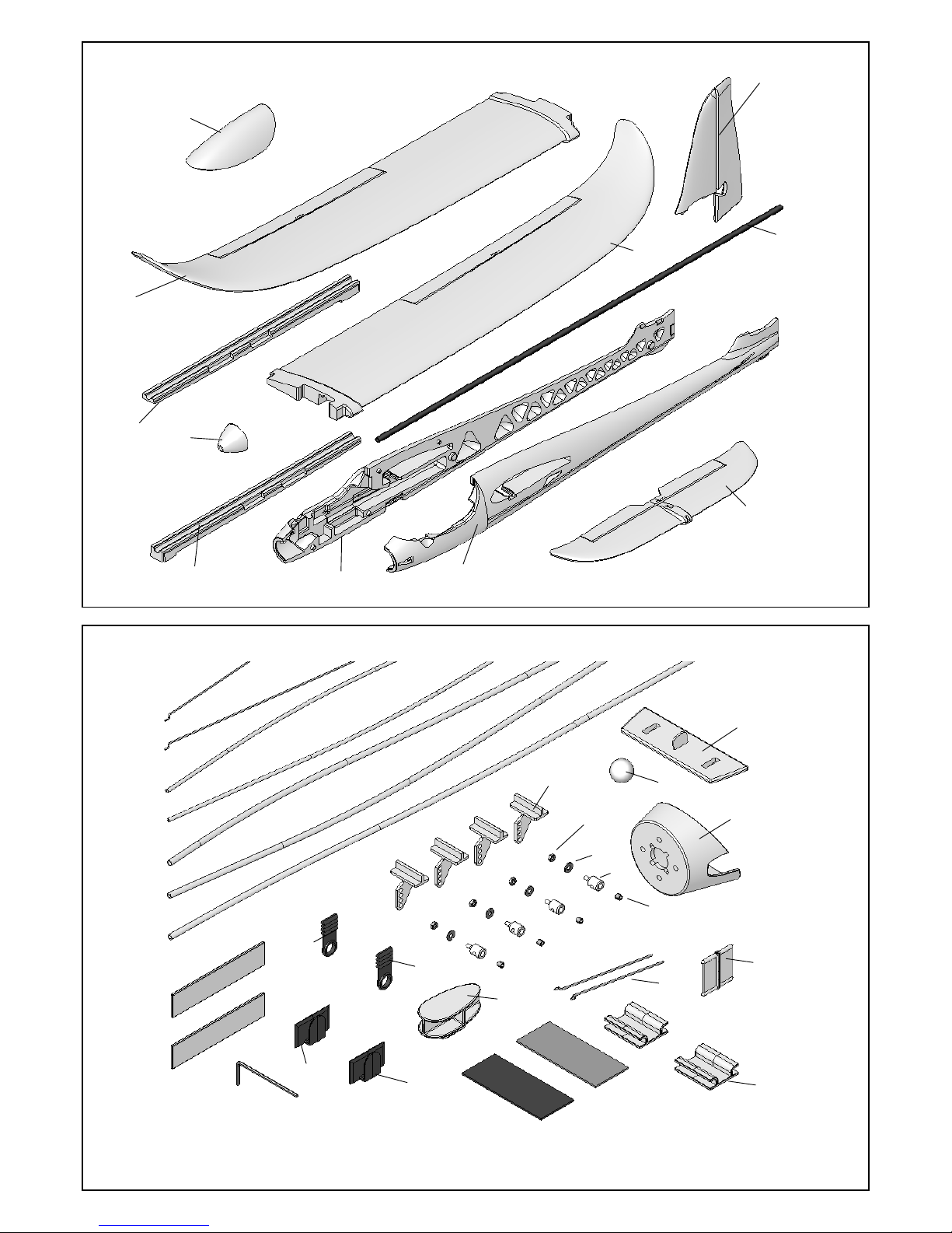
26
24
Abb. 1
Abb. 2
12
3
5
3
4
11
10
9
7
13
23
23
22
22
32
31
30
28
25
26
27
47
45
46
43
44
41
42
40
8
33
37
37
20 (2x)
21 (2x)
35
34
36
Page 27

27
Abb. 3
Abb. 5
Abb. 7
Abb. 9
3
41
45
43
3
43
3
CA
42
46
4
44
32
47
34
4
Abb. 4
Abb. 10
44
4
!
42
46
44
4 / 6
CA
4
43
45
41
Abb. 6
46
42
44
Abb. 8
44
CA
4
CA
Page 28
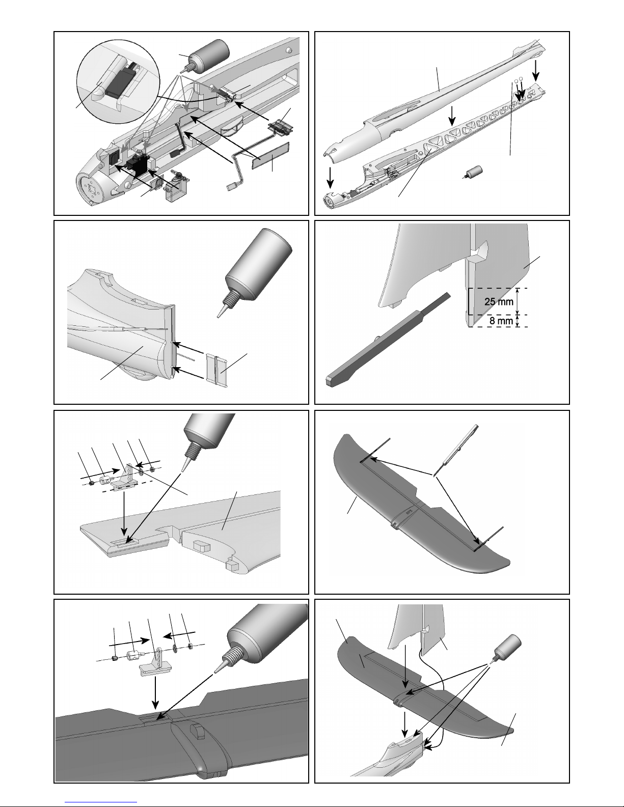
28
Abb. 11
Abb.13
Abb. 15
Abb. 17
37
CA
36
4
4
31
3
CA
25
27
28
32
47
12
4
Abb.12
Abb. 18
13
!
CA
4
33
3
Abb. 14
CA
Abb. 16
12
CA
36
22
CA
26
24
1mm
1mm
25
28
26
24
27
CA
Abb. 17
13
13
Page 29

29
Abb.19
Abb. 21
Abb. 23
Abb. 25
41
43
45
24
24
9
75 mm
9
40
23
36
Abb. 20
Abb. 26
3
CA
7
46
42
44
Abb. 22
Abb. 24
60 mm
8
1mm
1mm
25
28
26
24
27
35
Page 30
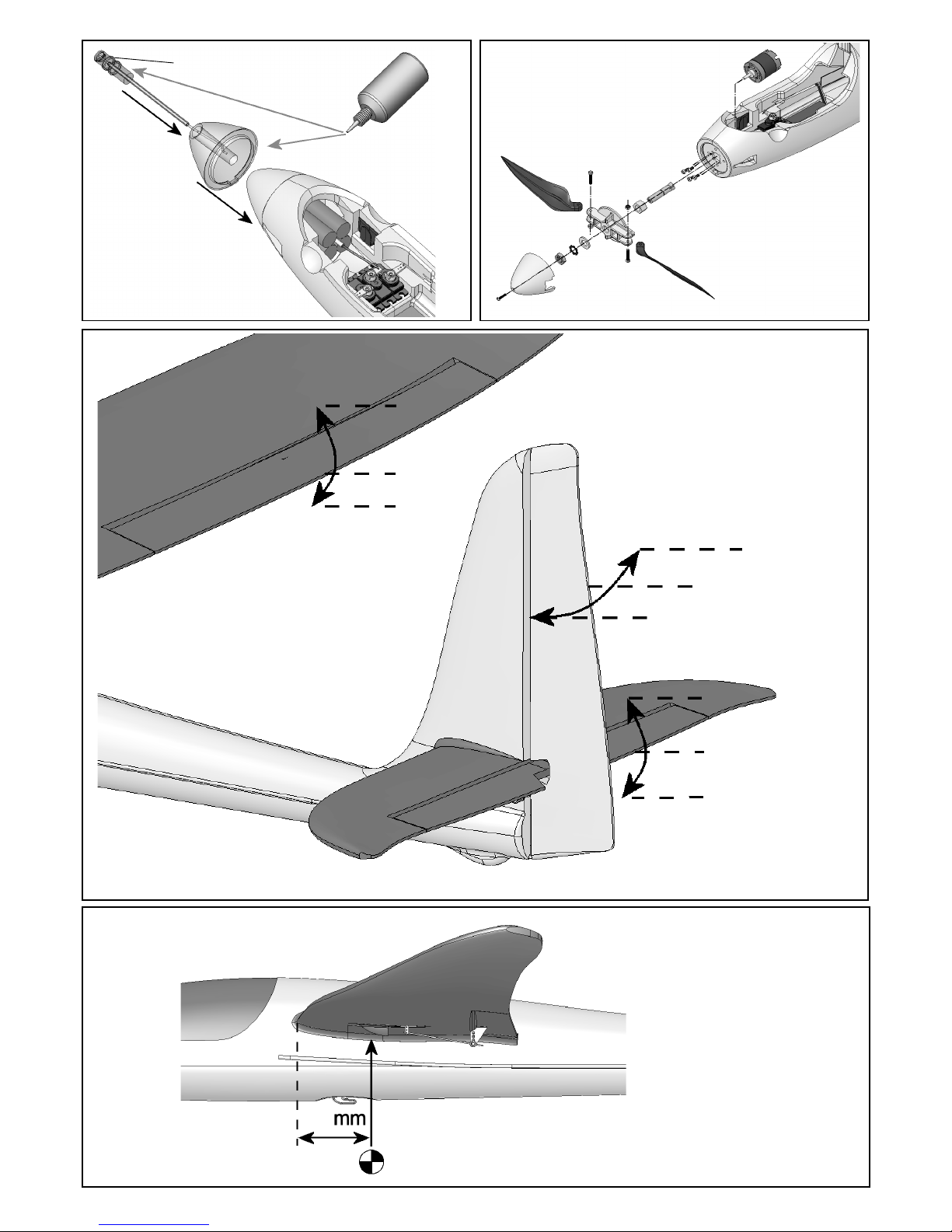
30
Abb.27
Abb. 29
# 72 3470
CA
Abb. 28
8 mm
70
7
Abb. 30
6 mm
15 mm
15 mm
8 mm
15 mm
Page 31

31
A
B
C
D
E
Auftriebskraft X
α
G
F
Grundlagen am Beispiel eines Flugmodells
Basic information relating to model aircraft
Bases du pilotage d’un modèle réduit
ozioni fondamentali
Principios básicos tomando como ejemplo un avión
Page 32

32
F
Bases du pilotage d’un modèle réduit
Un avion, comme un modèle réduit se pilote avec les gouvernes suivant 3 axes - l’axe vertiical, l’axe longitudinal et l’axe latéral.
Une action sur la commande de profondeur conduit à une modification de la position de vol autour de l’axe latéral. Une action sur
la gouverne de direction conduit à une modification de la position de l’appareil autour de son axe vertical. Si l’on agit sur les
ailerons, l’appareil tourne autour de son axe longitudinal. En fonction des paramètres extérieurs, par ex. des turbulences, qui
peuvent amener le modèle à quitter sa trajectoire, c’est au pilote d’effectuer les manoeuvres nécessaires pour ramener le modèle
dans la direction souhaitée. C’est en jouant au moteur (moteur, hélice) que l’on monte ou que l’on descend. Dans la plupart des
cas, la vitesse de rotation du moteur est réglée par un variateur.
Ce qui est important, c’est qu’en tirant sur la profondeur, le modèle monte, jusqu’à la limite du décrochage. L’angle de montée
dépend donc directement de la motorisation utilisée.
Le profil de l’aile
Le profil de l’aile est un profil creux autour duquel s’écoule l’air.
Les filets d’air qui passent sur le dessus de l’aile parcourent une
distance plus importante que ceux qui passent sur le dessous. Il
en résulte une dépression sur le dessus de l’aile qui maintient
l’appareil en l’air: c’est la portance. Vue A
Le centre de gravité
Comme tout autre appareil, votre modèle, pour avoir de bonnes
caractéristiques en vol, doit être centré correctement. C’est
pourquoi il est indispensable de centré correctement le modèle
avant le premier vol.
Le centre de gravité se mesure toujours en partant du bord
d’attaque de l’aile, le plus près possible du fuselage. Soutenu à
cet endroit par deux doigts ou mieux encore, posé sur la balance
de centrage MPX Réf. 69 3054, le modèle doit être et se maintenir
à l’horizontale. Vue B
Si le centrage correct n’a pas encore été atteint, celui-ci peut
l’être en déplaçant les éléments de rception, notamment l’accu
de propulsion. Si cela ne suffit toujours pas, rajoutez du plomb
soit à l’avant, dans le nez du fuselage ou à l’arrière, en le fixant
correctement. Si le modèle a tendance à basculer sur l’arrière,
rajoutez du plomb à l’avant, si c’est l’inverse, rajoutez du plomb
à l’arrière.
Angle d’incidence
C’est l’angle d’attaque que forme l’aile par rapport au
stabilisateur. En montant avec soin l’aile sur le fuselage (sans
jour) et le stabilisateur, l’angle d’incidence est automatiquement
respecté.
Si ces deux réglages ont été effectués avec minutie (centre de
gravité et angle d’incidence), vous n’aurez aucun problème lors
du premier vol. Vue C
Gouvernes et débattements des gouvernes
Vous ne pourrez obtenir de saines qualités en vol que si les
tringles de comùmande des gouvernes sont bien montées, sans
points durs, et que si les débattements des gouvernes sont
respectés. Les débattements indiqués dans la notice sont
recommandables pour les premiers essais, et nous vous
conseillons de les reprendre tels quels. Vous pourrez toujours
par la suite les adapter à votre style de pilotage.
Eléments de commande sur l’ématteur
Sur l’émetteur, il y a deux manches de commande pour la
commande des servos ce qui permet aux gouvernes de votre
modèle de bouger.
L’attribution des manches de commande se fait selon le mode
A, mais d’autres attributions sont possibles.
Les gouvernes ci-dessous sont commandés avec les
éléments de commande suivants:
Gouverne de direction (gauche/droite) Vue D
Gouverne de profondeur (haut/bas) Vue E
Aileron (gauche/droite) Vue F
Commande moteur (Marche/Arrêt)Vue G
L’élément de commande du moteur ne doit pas revenir
automatiquement au point neutre. C’est pourquoi c’est élément
de commande est cranté. Comment réglé ce «crantage» est
décrit dans la notice d’utilisation de la radiocommande.
Fuselage
Stabilisateur
Axe longitudinal
Axe vertical
Cône
Verrière
Aile gauche
Gouvernail de
direction
Élévateur
Dérive
Aileron droite
Axe latéral
Aileron gauche
Aile droite
Page 33

33
Liste des pièces
Kit EasyGlider PRO + electric BlueEdition
Nr. Nbr Désignation Matière Dimensions
1 1 Instructions de montage Papier DIN-A4
2 1 Planche de décoration Film autocollant 350 x 1000mm
3 1 Moitié fuselage gauche mousse Elapor Complet
4 1 Moitié fuselage droit mousse Elapor Complet
5 1 Nez de fuselage planeur mousse EPP Complet
7 1 Verrière mousse Elapor Complet
8 1 Aile gauche mousse Elapor Complet
9 1 Aile droite mousse Elapor Complet
10 1 Cache de clé d’aile gauche mousse Elapor Complet
11 1 Cache de clé d’aile droit mousse Elapor Complet
12 1 Profondeur mousse Elapor Complet
13 1 Dérive mousse Elapor Complet
Petit nécessaire
20 2 Velcro crochets plastique 25x60mm
21 2 Velcro velours plastique 25x60mm
22 2 Crochet pour système Canopy-Lock plastique injecté Complet
23 2 Téton de verrouillage Canopy-Lock plastique injecté Complet
24 4 Guignols à coller plastique injecté Complet
25 4 Corps de fixation des tringles métal Complet Ø6mm
26 4 Rondelle plate métal M2
27 4 Ecrou métal M2
28 4 Vis de blocage 6 pans métal M3x3mm
29 1 Clé 6 pan métal SW 1,5
30 2 Tringlerie pour ailerons embout en Z métal Ø 1x70mm
31 1 Charnière plastique injecté Complet
32 1 Crochet de remorquage / Glider plastique injecté Complet
33 2 Masselotte acier boulle Ø13mm
34 1 Support moteur plastique injecté Complet
35 1 Poigné pour verrière plastique injecté Complet
36 2 Support de câble plastique injecté Complet
37 2 Renfort de fuselage plastique injecté Complet
Tringlerie
40 1 Clé d’aile tube en fibre de verre Ø 10x8x1000mm
41 1 Tige avec embout en Z pour profondeur métal Ø 0,8 x 875mm
42 1 Tige avec embout en Z pour direction métal Ø 0,8 x 875mm
43 1 Gaine extérieure profondeur plastique Ø 3/2 x 785mm
44 1 Gaine extérieure direction plastique Ø 3/2 x 785mm
45 1 Gaine intérieure profondeur plastique Ø 2/1 x 850mm
46 1 Gaine intérieure direction plastique Ø 2/1 x 850mm
47 1 Tube guide antenne plastique Ø 3/2 x 785mm
Pièces de rechanges (voir également page 50/51; S.V.P. à commander chez votre revendeur)
Planche de décoration 72 4236
Planche de décoration electric BlueEdition 72 4239
Moitiés de fuselage + tringlerie 22 4150
Verrière 22 4151
Ailes 22 4159
Petit nécessaire 22 4152
Clé d’aile 72 3190
Système Canopy-Lock (fermeture de verrière) 72 5136
Kit d’ailes 22 4160
F
Page 34

34
KIT EasyGlider PRO + electric BlueEdition
Prenda confidenza con il contenuto della scatola di montaggio!
Le scatole di montaggio MULTIPLEX sono soggette, durante la produzione, ad un continuo controllo della qualità e siamo pertanto
certi che Lei sarà soddisfatto con il contenuto della scatola di montaggio. La preghiamo tuttavia, di controllare tutte le parti prima del
loro utilizzo (consultando la lista materiale), poiché le p arti già lavorate non potranno più essere sostituite. Se una p arte dovesse
risultare difettosa, provvederemo, dopo un nostro controllo, ad effettuare la riparazione o la sostituzione. Inviare la parte in questione
al nostro reparto modellismo, allegando assolutamente lo scontrino fiscale e una breve descrizione del difetto.
Noi lavoriamo costantemente al miglioramento tecnico dei nostri modelli. Cambiamenti nel contenuto della scatola di montaggio, in
forma, dimensioni, tecnica, materiali ed accessori, sono possibili in ogni momento e senza preavviso. Per tutto quanto qui descritto,
per i disegni e le foto, non si assumono responsabilità.
Attenzione!
Modelli radiocomandati, e specialmente aeromodelli, non sono giocattoli in senso stretto. La loro costruzione e uso richiedono
conoscenza tecnica, accuratezza nella costruzione, nonché disciplina e consapevolezza dei rischi. Errori ed imprecisioni
nella costruzione e nel funzionamento possono provocare danni a persone e cose. Richiamiamo espressamente l’attenzione
su questi pericoli, poiché non possiamo controllare il corretto assemblaggio, la manutenzione ed il funzionamento dei nostri
modelli.
Per completare i modelli EasyGliderPRO sono necessari i seguenti componenti:
Colla: cianoacrilica:
Usare colla cianoacrilica di media viscosità Zacki ELAPOR # 85 2727 – non usare colla ciano per espanso! Colle epossidiche
possono sembrare a prima vista ideali, in caso di sollecitazione, la colla si stacca facilmente dalle parti in espanso – l’incollaggio è
solo superficiale. In alternativa si può anche usare colla a caldo!
Componenti RC MUL TIPLEX per EasyGlider PRO:
Ricevente RX-5 light M-Link Art.nr. 5 5808
oppure Ricevente RX-5 M-Link (telemetria) Art.nr. 5 5917
Servo Tiny-S UNI (necessari 2 pz.) elevatore / direzionale Art.nr. 6 5121
Servo Nano-S UNI (necessari 2 pz.) alettoni Art.nr. 6 5120
oppure Tuning-Servo Tiny-MG (necessari 2 pz.) elevatore / direzionale Art.nr. 6 5122
Tuning-Servo Nano-PRO MG (necessari 2 pz.) alettoni Art.nr. 6 5119
Prolunga 400 mm UNI (necessari 2 pz.) servo alettoni Art.nr. 8 5029
Prolunga 300 mm UNI (necessari 2 pz.) servo alettoni Art.nr. 8 5031
Caricabatterie:
MULTIcharger L-703 EQU 230V Art.nr. 9 2523
oppure Combo MULTIcharger LN-3008 EQU e Aliment. AC/DC 230V/12V 5,0A Art.nr. 9 2545
Set motorizzazione EasyGlider PRO
Set motorizzazione "EasyGlider PRO 3S STANDARD" Li-BATT powered Art.nr. 33 3651
Set motorizzazione "EasyGlider PRO 3S STANDARD" Art.nr. 33 2651
Tuning Set motorizzazione EasyGlider PRO
Set motorizzazione "EasyGlider PRO 3S TUNING" Li-BATT powered Art.nr. 33 3650
Set motorizzazione "EasyGlider PRO 3S TUNING" Art.nr. 33 2650
Pacchi batteria
Li-BATT eco 3/1-2000 (M6) 2000 mAh Art.nr. 15 7231
Li-BATT eco 3/1-3000 (M6) 3000 mAh Art.nr. 15 7236
Componenti ulteriormente necessari per la versione aliante
Pacco batteria Rx (NiMh) 4 / 2100mAh Art.nr. 15 6052
Interruttore mini Rx con presa di carica Art.nr. 8 5045
Gancio traino Art.nr. 72 3470
Attrezzi: Forbice, taglierino, pinza tronchese
Nota: Per una più facile consultazione, staccate dal centro le pagine con i disegni!
Dati tecnici: aliante aliante elettrico
Apertura alare 1.800 mm 1.800 mm
Lunghezza sopra tutto 1.130 mm 1.130 mm
Peso in ordine di volo ca. 800 g con motorizzazione di serie ca. 980 g
Superficie alare FAI ca. 41,6 dm² FAI ca. 41,6 dm²
Carico alare ca. 20 g/dm² ca. 24 g/dm²
Funzioni RC elevatore, direzionale e alettoni in aggiunta motore
I
Page 35

35
Nota importante
Questo modello non è in polistirolo™! Per questo motivo non usare per gli incollaggi colla vinilica o epoxy. Usare
esclusivamente colla cianoacrilica, possibilmente assieme all’attivatore (Kicker). Per tutti gli incollaggi usare colla ciano di
media viscosità. Con il materiale Elapor® spruzzare sempre su una superficie l’attivatore (Kicker) – fare asciugare per 2
minuti ed applicare sulla superficie opposta la colla ciano. Unire e allineare immediatamente le parti.
Attenzione quando si lavora con la colla cianoacrilica. Questo tipo di colla asciuga in pochi istanti; in nessun caso applicare
sulle dita o su altre parti del corpo. Proteggere assolutamente gli occhi con occhiali di protezione adeguati!
Fig. 8
4. Installare la guaina per l’antenna
Adattare ed eventualmente accorciare la guaina 47. Incollarla
infine nel semiguscio destro – fare attenzione a non piegare la
fusoliera! Fig. 9
5. Installare il gancio catapulta (solo per la versione aliante)
Per la versione aliante, incollare il gancio 32 nella rispettiva
sede, nel semiguscio destro della fusoliera 4.
Fig. 9
6. Installare il supporto motore
Incollare il supporto motore 34 nel semiguscio destro – fare
attenzione che la colla non coli dalle due parti incollate. In questa
fase, non applicare ancora la colla sulla superficie opposta del
supporto motore. Per aumentare il grado di stabilità della
fusoliera, incollare il supporto motore anche per la versione
aliante.
Fig. 10
7. Installare i servi nei semigusci della fusoliera
Con l’ausilio della radio, portare i servi in posizione neutrale.
Inserire i servi, come indicato in Fig. 11, lateralmente nel
semiguscio destro e sinistro. A seconda dei servi usati,
potrebbero essere necessari piccoli lavori di ritocco.
Passare i cavi dal basso verso l’alto, nelle rispettive scanalature
e fissarli con nastro adesivo. Fissare i servi, applicando una
goccia di colla ciano fra le linguette e l’espanso. Inserire infine
la “Z” dei tondini nelle squadrette ed installare queste ultime
sul servo, con un angolo di 90° (avvit are la vite). Incollare i
ganci di chiusura 22 a destra e sinistra nei semigusci fusoliera.
Incollare le prese delle prolunghe, a filo nei supporti 36. Incollare
infine i supporti 36 a destra e sinistra nelle rispettive sedi.
Posizionare i cavi ed incollare le ordinate di rinforzo 37.
Fig. 11
8. Unire i semigusci
La colla più ideale per unire i semigusci fusoliera è sicuramente
la colla ciano densa, usata assieme all’attivatore.
.
Attenzione: per la versione Tunig, incollare ancora 2 pesi di
compensazione 33, come indicato in Fig. 12.
Unire le parti 3 + 4 dapprima senza colla e controllare che
combacino perfettamente -eventualmente ritoccare.
Spruzzare sul semiguscio 4 l’attivatore e fare asciugare per ca.
2 minuti.
Applicare sul semiguscio 3, sui rispettivi punti di contatto e sul
supporto motore, la colla ciano. Unire al semiguscio 4 e allineare
accuratamente le parti! La giuntura fra le due parti deve essere
perfettamente rettilinea!
Fig. 12
9. Installare la cerniera del direzionale
Incollare la cerniera 31, con poca colla ciano, nella parte
posteriore della fusoliera. Fare attenzione che la colla non coli
all’interno della cerniera.
Fig. 13
Tenere lontano dalla portata dei bambini!
1. Prima di cominciare
Controllare il contenuto della scatola di montaggio, consultando
le Fig. 1+2 e la lista materiale.
Terminare la fusoliera ed i piani di coda
2. Preparare i rinvii
Controllare la lunghezza dei tubi bowden 43 e 45 per l’elevatore,
se necessario accorciarli.
43 Ø 3/2 x 785 mm
45 Ø 2/1 x 850 mm
inserire il tondino d’acciaio 41 Ø 0,8 x 875 mm
Controllare, e se necessario accorciare, anche i tubi bowden
44 e 46 per il direzionale.
44 Ø 3/2 x 785 mm
46 Ø 2/1 x 850 mm
inserire il tondino d’acciaio 42 Ø 0,8 x 875 mm
Guaina per antenna 47 Ø 3/2 x 785 mm
(eventualmente accorciare)
3. Installare i rinvii nei semigusci della fusoliera
Attenzione: l’incollaggio accurato delle guaine esterne 43 e
44 e della guaina 47 per l’antenna sull’intera lunghezza della
fusoliera fa aumentare sensibilmente il grado di stabilità della
fusoliera stessa.
Fare attenzione che la colla non coli all’interno delle guaine e
che i rinvii si muovano con facilità.
Semiguscio sinistro:
Inserire il bowden completo per l’elevatore (lunghezza tondino
acciaio = 875mm) nella parte sinistra della fusoliera, con la “Z”
rivolta verso il servo.
Fig. 3
L’estremità anteriore della guaina esterna 43 deve essere
posizionata a filo con la fusoliera, come indicato in Fig. 4.
Appoggiare il guscio fusoliera su una superficie piana. Incollare
quindi la guaina esterna 43 sull’intera lunghezza con colla ciano.
Fig. 5
Semiguscio destro:
Inserire il bowden completo per il direzionale (lunghezza tondino
acciaio = 875mm) nella parte destra della fusoliera, con la “Z”
rivolta verso il servo.
Fig. 6
L’estremità anteriore della guaina esterna 44 deve essere
posizionata a filo con la fusoliera, come indicato in Fig. 7.
Appoggiare il guscio fusoliera su una superficie piana
(attenzione alle linguette / posizionare parte del semiguscio in
piano, oltre al bordo del tavolo). Incollare quindi la guaina
esterna 44 sull’intera lunghezza con colla ciano.
Page 36
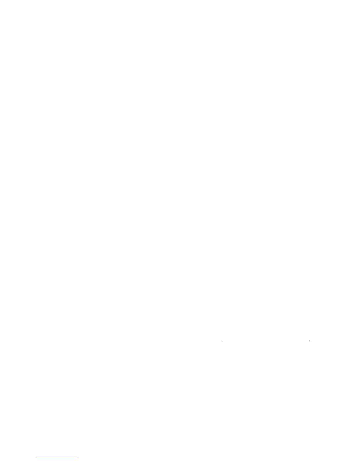
36
Con un taglierino, praticare sulla parte anteriore del direzionale,
esattamente al centro, una scanalatura per la cerniera 31.
Attenzione a non tagliarsi! La scanalatura sul timone 5 deve
essere allungata verso il basso di ca. 3-4 mm, in modo da
riuscire ad installare successivamente con più facilità il
direzionale e l’elevatore sulla fusoliera.
10. Fissare la squadretta sul direzionale
Accorciare la parte a “T” della squadretta 24 per il direzionale
13 a ca. 2 mm (pinza tronchese). Inserire il raccordo 25 nel
secondo foro dall’interno e fissarlo con una rondella 26 e dado
27. Attenzione: controllare che il raccordo sia installato nella
giusta direzione! Serrare attentamente il dado – il raccordo deve
girare, senza gioco. Bloccare infine il dado con una goccia di
colla ciano (applicare con un ago). Con la chiave a brugola 29
avvitare il grano 28 nel raccordo 25.
Spruzzare l’attivatore nella rispettiva sede per la squadretta
sul direzionale ed incollare infine la squadretta 24 con i fori
rivolti verso la “cerniera”.
Fig. 14
11. Rendere mobili l’elevatore ed il direzionale
Tagliare l’elevatore 12 sui due lati (scanalatura di 1mm). Per
rendere mobili l’elevatore ed il direzionale, piegarli a destra/
sinistra per qualche volta – in nessun caso staccare i timoni!
Fig. 16
12. Fissare la squadretta sull’elevatore
Inserire il raccordo 25 nel foro più esterno della squadretta 24
e fissarlo con una rondella 26 e dado 27. Attenzione: controllare
che il raccordo sia installato nella giusta direzione! Serrare
attentamente il dado – il raccordo deve girare, senza gioco.
Bloccare infine il dado con una goccia di colla ciano (applicare
con un ago). Con la chiave a brugola 29 avvitare il grano 28 nel
raccordo 25.
Con colla ciano, incollare la squadretta 24, con i fori rivolti verso
la “cerniera”. Prima dell’incollaggio, spruzzare l’attivatore nella
rispettiva sede sull’elevatore.
Fig. 17
13. Unire i piani di coda
Incollare il piano di quota 12 ed il direzionale 13 esattamente a
90°. Per il controllo utilizzare p.es. un goniometro.
Fig. 18
14. Incollare i piani di coda sulla fusoliera
Posizionare prima senza colla, il piano di quota ed il direzionale
sulla fusoliera e controllare che tutto combaci perfettamente.
Inserire a tale proposito prima la cerniera 31 nel direzionale
13, poi spingere in avanti i piani nella loro posizione definitiva.
Fare attenzione che l’elevatore 12 poggi perfettamente sulla
fusoliera, in linea con la superficie d’appoggio delle ali – davanti
nella fusoliera. Per facilitare l’allineamento, inserire la baionetta
40 nella sede alare e fissarla con nastro adesivo. Quando tutto
combacia, incollare le parti e controllare nuovamente
l’allineamento e l’appoggio perfetto sulla fusoliera! Questa fase
della costruzione deve essere eseguita con particolare cura,
per ottenere delle buone doti di volo del modello.
15. Collegare i rinvii dell’elevatore e del direzionale
Inserire le estremità dei tondini 41 e 42 nei raccordi 25 – portare
i servi ed i timoni in posizione neutrale ed avvitare i grani 28.
Fig. 19 + 20
Terminare le ali
16. Rendere mobili gli alettoni
Sulle semiali 8 e 9 t agliare lateralmente gli alettoni (scanalatura
di 1mm). Per renderli mobili, piegarli a destra/sinistra per
qualche volta – in nessun caso staccare i timoni!
Fig. 21
17. Fissare le squadrette sugli alettoni
Inserire rispettivamente un raccordo 25 nel foro più esterno
delle squadrette 24 e fissarli con una rondella 26 e dado 27.
Attenzione: 1x destra, 1x sinistra! Serrare attentamente il dado
– il raccordo deve girare, senza gioco. Bloccare infine il dado
con una goccia di colla ciano (applicare con un ago). Con la
chiave a brugola 29 avvitare il grano 28 nel raccordo 25.
Con colla ciano, incollare le squadrette 24, con i fori rivolti verso
la “cerniera”, nelle rispettive sedi. Prima dell’incollaggio,
spruzzare nelle sedi dell’attivatore.
Fig. 22
18. Installare i servi per gli alettoni
Con la radio, portare i servi in posizione neutrale ed installare
le squadrette a 90°, in modo che la squadrett a sporga
lateralmente dal servo -1x destra e 1x sinistra.
Inserire i servi nelle rispettive sedi delle semiali 8 e 9. A seconda
dei servi usati, potrebbero essere necessari piccoli lavori di
ritocco. Per fissare i servi, applicare rispettivamente una goccia
di colla a caldo nelle scanalature per le linguette ed inserire
immediatamente il servo – eventualmente ritoccare ancora
successivamente con la colla a caldo.
Fig. 23
19. Installare i rinvii per gli alettoni
Agganciare la “Z” dei tondini d’acciaio 30 nel foro più esterno
della squadretta del servo ed infilare l’estremità opposta nel
raccordo 25. Portare i servi ed i timoni in posizione neutrale ed
avvitare i grani 28.
Fig. 23
20. Posizionare i cavi dei servi alari
Posizionare i cavi sul fondo, nelle rispettive scanalature, in
direzione dell’apertura per la baionetta e allungarli con la
prolunga da 400mm. Le prolunghe possono essere saldate o
collegate con i rispettivi connettori. Per i connettori è prevista
una sede nei coperchi baionetta 10 e 11. Posizionare i cavi in
modo rettilineo e con il lato stretto del cavo rivolto verso l’alto.
I cavi devono sporgere dall’ala (misurare sulla parte inferiore
dell’ala) a sinistra 60 mm e a destra 75 mm, in modo da riuscire
a collegare i servi alari ai connettori inseriti nel supporto 36,
installato nella fusoliera. Posizionare e fissare il cavo rimanente
nella scanalatura alare.
Fig. 23+24
21. Incollare i coperchi baionetta
Adattare con cura i coperchi baionetta 10 e 1 1 nelle semiali 8 e
9. Quando tutto combacia, incollare con colla ciano, facendo
attenzione che la colla non coli sulle superfici dove
successivamente verrà inserita la baionetta 40. La baionetta
40 deve essere inserita solo quando si è certi che la colla
all’interno dell’ala sia perfettamente asciutta (per sicurezza
spruzzare dell’attivatore e attendere ca. 5 minuti), altrimenti
può succedere che non si riesca più ad estrarre la baionetta.
Posizionare i cavi dei servi alari nelle scanalature previste nei
coperchi baionetta e fissarli con colla (colla a caldo o colla a
contatto). Non utilizzare colla ciano. Questo tipo di colla fa
screpolare il materiale plastico che isola i cavi.
Fig. 23
22. Controllare il montaggio delle ali
Installare le semiali con l’ausilio della baionetta 40. S pingere le
ali fino ad una distanza di 5 cm a destra e sinistra dalla fusoliera.
Collegare le spine dei servi alari alle rispettive prese. Unire le
semiali e contemporaneamente posizionare i cavi.
Controllare che le semiali 8 e 9 combacino perfettamente con
la fusoliera, eventualmente ritoccare attentamente in questo
modo: premere attentamente con le dita il bordo alare che verrà
successivamente inserito nella fusoliera.
Nota: Non incollare le ali con la fusoliera, in modo da riuscire
Page 37

37
a smontare il modello, per rendere più facilitare il trasporto.
Fig. 25
23. Incollare le linguette di fissaggio nella capottina
Incollare dapprima il supporto capottina 35 sotto la capottina
7. Poi posizionare per prova le due linguette di chiusura 23, a
filo con il supporto capottina . Adesso applicare sulla parte
dentata colla ciano densa – in questa fase non usare
l’attivatore!-, inserire le linguette nelle rispettive sedi della
capottina. Posizionare la capottina sulla fusoliera, in modo che
le linguette vadano ad agganciasi ai ganci 22. Allineare
immediatamente, attendere ca. 1 minuto, poi aprire
attentamente la capottina. Spruzzare sulle superfici incollate
l’attivatore.
Fig. 26
24. Installare l’impianto radio (in generale)
Installare adesso i componenti rimanenti dell’impianto radio
nell’area della capottina. Già in questa fase posizionare il pacco
batteria e la ricevente in modo da riuscire a bilanciare il modello.
Per fissare i singoli componenti usare il velcro allegato 20+21.
La colla del velcro non aderisce a sufficienza sull’espanso. Per
questo motivo incollare ulteriormente il velcro con la colla ciano.
Per entrambe le versioni, fissare la ricevente dietro ai servi
utilizzando il velcro allegato. Inserire l’antenna nella guaina
bowden 47 installata precedentemente, aiutandosi con un
tondino d’acciaio appuntito. Inserire il tondino da dietro nella
guaina, infilare sul tondino l’estremità dell’antenna,
eventualmente fissarla ulteriormente con una goccia di ciano,
ed estrarre il cavo.
Il modello è predisposto per l’installazione di un gancio traino
MPX # 72 3470. Incollare il gancio nella punta fusoliera 5.
Installare una guaina bowden dal gancio, passando per il pacco
batteria, in direzione del servo. Per il rinvio utilizzare un tondino
d’acciaio Ø 1,2 mm.
Fig. 27
25. Installare l’impianto radio nella versione elettrica
I componenti consigliati sono provati e si adattano perfettamente
al modello. L’installazione di componenti diversi, in particolare
di motorizzazioni più potenti, solo a proprio rischio.
Installare il motore e fissarlo saldamente con tutte le viti.
Posizionare il cavo di collegamento in modo che non entri in
contatto con le parti in movimento del motore. Fissare il cavo
con nastro adesivo.
Fig. 28
Fissare il regolatore di giri, accanto alla ricevente sul lato della
fusoliera, utilizzando il velcro allegato.
Posizionare il pacco batteria nell’area dietro alla ricevente. Il
pacco batteria deve essere posizionato in modo da riuscire a
bilanciare il modello con il minimo di zavorra. Una volta
determinata la giusta posizione, fissarlo con il velcro.
Per prova collegare tutti i componenti, come riportato sulle
istruzioni allegate alla radio. Controllare che tutti i cavi siano
posizionati senza tensione.
Installare il mozzo portapale, ad una distanza di 1 mm dalla
fusoliera.
Fissare infine le pale dell’elica sul portapale. Avvitare
completamente le rispettive viti, evitando di serrarle troppo - le
pale dell’elica si devono chiudere, alzando la punta della
fusoliera.
Accendere la radio e collegare il pacco batteria al regolatore ed il
regolatore alla ricevente. E’ indispensabile che il regolatore
disponga della funzione BEC (alimentazione dell’impianto RC dal
pacco batteria).
Tenere saldamente il modello, togliere da dietro l’elica qualsiasi
oggetto leggero - accendere per un attimo il motore e controllare
il senso di rotazione dell’elica.
Attenzione: anche con piccoli motori elettrici ed eliche ci
si può ferire seriamente!
26. Regolare le corse dei timoni
Per ottenere un comportamento di volo equilibrato del modello
è importante regolare correttamente le corse dei timoni. Le corse
devono essere misurate sempre nel punto più largo dei timoni.
Elevatore
verso l’alto - stick tirato - ca. + 8-10mm
verso il basso - stick in avanti - ca. – 8-10 mm
Direzionale
a destra e sinistra
rispettivamente ca. 15-20mm
Alettoni
verso l’alto ca. +15 mm
verso il basso ca. – 6 mm
Spoiler – entrambi gli alettoni alzati ca. +20 mm
Miscelazione Spoiler in elevatore ca. – 4 mm
Fig. 29
La funzione “Spoiler” permette di alzare entrambi gli alettoni
per accorciare l’atterraggio. Contemporaneamente è necessario
miscelare l’elevatore a picchiare per mantenere il modello in
una fase di volo stabile. Per usare questa funzione devono
essere presenti sulla radio i mixer necessari.
Consultare a tale proposito le istruzioni allegate al
radiocomando.
Nota: con alettoni a destra, l’alettone di destra (visto in direzione
di volo) deve muoversi verso l’alto.
Se la radio usata non consente di impostare le corse riportate
sopra, si dovrà intervenire di conseguenza sui rinvii, collegandoli
ad un foro più esterno/interno.
27. Ancora qualche cosa per l’estetica
La scatola di montaggio contiene dei decals multicolore 2.
Ritagliare le scritte e gli emblemi ed incollati come indicato sulle
foto della scatola di montaggio o secondo i propri gusti.
28. Bilanciare il modello
L’ EasyGlider/PRO, come ogni altro aereo, deve anche essere
bilanciato su un punto prestabilito, per ottenere delle doti di
volo stabili. Montare il modello. Eventuali correzioni possono
essere fatte spostando il pacco batteria Rx / pacco batteria
motore. Se questo non dovesse essere sufficiente, usare del
piombo di bilanciamento.
Il baricentro si trova a 70mm dal bordo d’entrata dell’ala, in
prossimità della fusoliera. Segnare il punto sulla parte inferiore
delle ali con un pennarello indelebile.
Sollevando il modello in questo punto con le dita, dovrebbe
rimanere in posizione orizzontale. Eventuali correzioni possono
essere fatte, spostando il pacco batteria Rx / pacco batteria
motore. Una volta effettuato il bilanciato, segnare la posizione
del pacco batteria, in modo da posizionare il pacco batteria
sempre nella stessa posizione. Fig. 30
29. Preparativi per il primo volo
Per il primo volo è consigliabile scegliere una giornata priva di
Page 38
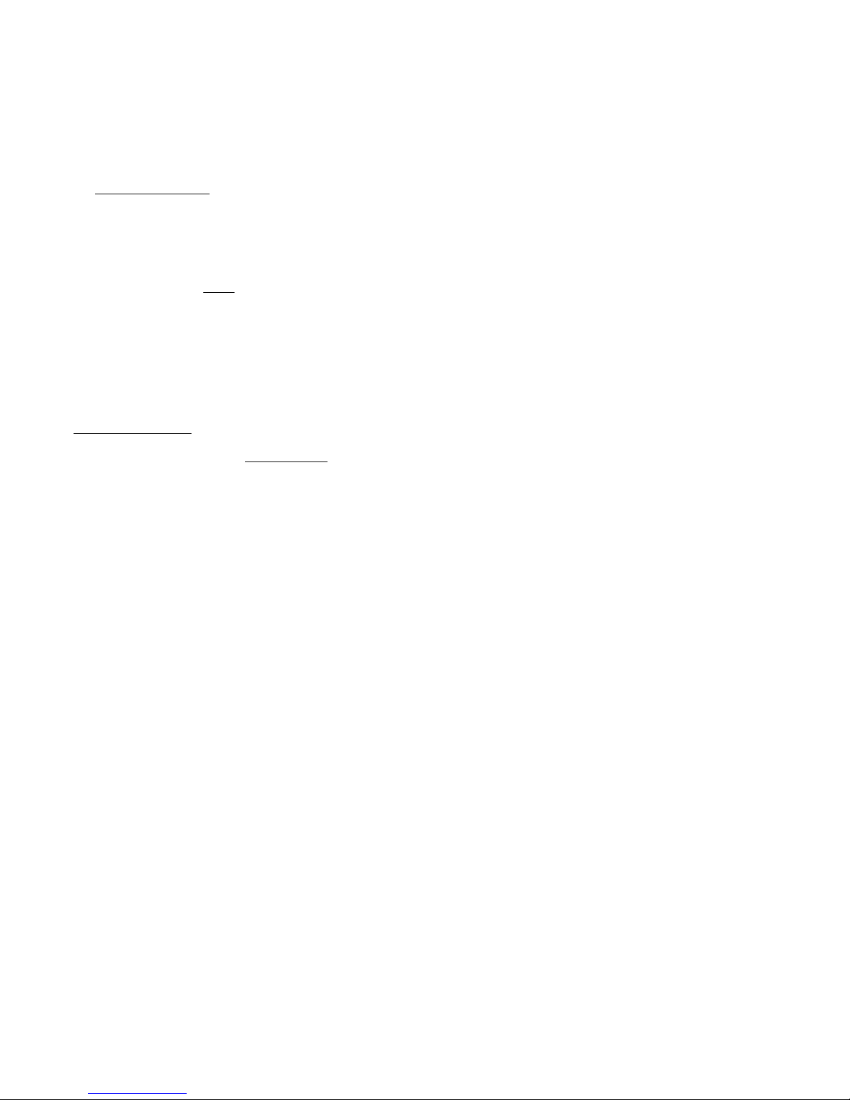
38
vento. Particolarmente indicate sono spesso le ore serali.
Se non si ha ancora esperienza nel campo dell’ aeromodellismo
RC, farsi aiutare da un modellista esperto. L ’esperienza insegna
che spesso i primi voli non vanno a “buon fine” se fatti senza
l’aiuto di un esperto. Contattare l’associazione di modellismo
della zona o chiedere indirizzi al proprio rivenditore.
Per facilitare l’approccio al modellismo si può anche usare il
nostro simulatore di volo per PC.
Il simulatore può essere scaricato a titolo gratuito dal nostro
sito www.multiplex-rc.de. Il cavo d’interfaccia per radio MPX
è disponibile presso il Suo rivenditore (Art.nr. 8 5153)
Prima del decollo effettuare assolutamente un test di ricezione
dell’impianto RC!
Le batterie della radio e del modello devono essere caricate
secondo le prescrizioni. Prima d’accendere la radio, accertarsi
che il canale usato sia libero.
Un aiutante si allontana con la radio e muove costantemente una
funzione di comando; l’antenna della radio deve essere
completamente inserita.
Durante l’allontanamento muovere uno stick. Controllare i servi.
Il servo che non viene mosso, deve rimanere fermo fino ad una
distanza di ca. 60 m, mentre quello che viene comandato con lo
stick, deve muoversi normalmente, senza ritardi. Questo test deve
essere effettuato solo quando non ci sono altre radio accese,
neanche su altri canali, e quando non ci sono interferenze sulla
propria banda di frequenza!
Il test deve essere ripetuto con il motore acceso. La distanza di
ricezione deve rimanere pressoché uguale.
Non decollare assolutamente se dovessero sorgere dei
problemi. In questo caso fare controllare la propria radio (con
batterie, interruttore, servi) dalla ditta produttrice.
Primo volo ...
Aliante:
Con un lancio a mano diritto e contro vento si può determinare
con facilità se il modello è regolato correttamente o se richiede
ancora correzioni con le leve dei trim. Se il modello tende a
girare su un lato, trimmare il direzionale dalla parte opposta.
Se un’ala si “abbassa” immediatamente, correggere sugli
alettoni.
Decollo con corsa:
In questo caso il modello viene fatto decollare nello stesso modo
come si usa per un aquilone. Fissare ad un’estremità della corda
l’anello e una bandierina . Agganciare l’anello al gancio 32
sulla parte inferiore del modello, stendere la corda. Un aiutante
comincia a correre con l’estremità opposta della corda (sempre
controvento). Con la corda in tensione rilasciare il modello.
Durante la corsa, l’aiutante deve controllare il modello.
Specialmente con vento forte si deve fare attenzione a non
sollecitare eccessivamente il modello.
Decollo con catapulta
Questo tipo di decollo è particolarmente adatto per un modello
di queste dimensioni. Il decollo con catapulta non richiede
aiutanti e permette inoltre di raggiungere un’altezza
considerevole di ca. 100 m, che può essere sfruttata per la
ricerca di termiche.
Volo in termica
Lo sfruttamento delle termiche richiede esperienza da parte del
pilota. Le termiche i pianura, a causa la maggiore quota del
modello, sono più difficili da riconoscere che in pendio, dove
spesso le termiche si possono trovare “di fronte” al pilota. Solo
pochi piloti esperti riescono a riconoscere una termica in pianura
“sopra la loro testa” e a farsi portare in quota – per questo motivo,
volare trasversalmente davanti alla propria posizione.
Un campo ascendente si riconosce dal comportamento del
modello; le buone termiche fanno salire velocemente il modello,
le piccole, invece, richiedono tutta l’esperienza del pilota. Con
qualche esercizio si riuscirà a riconoscere i punti di distacco delle
termiche nell’area di volo. L’aria si riscalda, a seconda della
capacità del terreno di trasmettere il calore del sole e viene
spostata dal vento a poca distanza da terra. La “bolla” d’aria calda
si può staccare da terra e cominciare a salire per colpa di un
cespuglio, di una siepe, per un bosco o di una collina, per una
macchina che passa nelle vicinanze, anche per un aeromodello
in atterraggio. Un bell’ esempio, però in senso inverso, si ha
quando una goccia scivola sotto ad un rivestimento, rimane
dapprima attaccata, cade però appena incontra un ostacolo.
Anche in alta montagna, sul confine con zone innevate si possono
facilmente trovare termiche. Sopra la zona innevata, l’aria fredda
scende verso il basso, incontrando al confine dell’area l’aria calda
che sale dalla valle; questa porta ad un distaccamento di forti,
ma anche “turbolente” termiche. Cercare di sfruttare sempre al
meglio le termiche - con piccole correzioni, tenere il modello
sempre al centro della termica, dove le correnti ascendenti sono
maggiori. Questo richiede esperienza ed esercizio.
Per non perdere di vista il modello, uscire in tempo dalla zona di
ascendenza. Si noti che il modello è più facilmente visibile sotto
ad una nuvola, che nel cielo terso blu. Se si riduce la quota:
Il modello EasyGlider PRO può sopportare alte sollecitazioni, però
anche queste hanno un limite. Naturalmente la garanzia non copre
i danni dovuti ad un’eccessiva sollecitazione del modello.
Volo in pendio
Il volo in pendio è sicuramente il modo più piacevole per volare
un aliante. Volare per ore, portati dal vento del pendio, senza
dover ricorrere a verricello o traino - un’esperienza ineguagliabile.
Il culmine è certamente il volo in termica, partendo dal pendio.
Lanciare il modello, volare fuori, sopra la valle, cercare la termica,
farsi portare fino in quota, scendere in acrobazia, per ricominciare
il gioco, questo è modellismo alla perfezione.
Però attenzione, il volo in pendio nasconde anche pericoli.
L’atterraggio è certamente più difficile che in pianura. Spesso si
deve atterrare nell’area turbolenta di sottovento, cosa che richiede
concentrazione e un avvicinamento corretto e veloce. Un
atterraggio in sopravvento, cioè nell’ascendenza del pendio, è
ancora più difficile. Normalmente si atterra velocemente, salendo
il pendio, con la “ripresa” nel momento giusto, poco prima
dell’atterraggio.
Traino
I modelli Magister e EasyGlider sono la coppia ideale per il traino.
Se il decollo deve avvenire sull’erba, è indispensabile che il
Magister sia motorizzato con un motore più potente, p.es.
brushless con ca. 300 Watt di potenza.
Per il traino usare una corda intrecciata con un diametro di ca.
1 – 1,5 mm e lunga ca. 20 m.
Sull’altra estremità della corda, praticare un nodo scorsoio con
filo di nylon da 0,5 mm (punto di rottura programmato) e
collegare al gancio traino (# 72 3470) dell’ EasyGlider PRO.
Fig. 27
L’altra estremità della corda deve essere agganciat a al rispettivo
gancio del Mentor. Posizionare i due modelli, uno dietro l’altro
controvento. La corda deve passare sopra l’elevatore del Magister.
Rullare lentamente con il modello che traina per tendere la corda.
Solo adesso dare tutto motore – il trainatore rimane a terra –
l’aliante decolla rimanendo a poca distanza dal suolo – adesso
può anche decollare il modello che traina. Salire in modo costante
(anche nelle curve!!!) Durante i primi traini evitare di sorvolare
piloti e spettatori. Una volta raggiunta la quot a di sgancio, portare
i modelli in orizzontale, togliere motore e sganciare l’aliante.
Page 39

39
Volo elettrico
Con la versione elettrica, EasyGlider Electric si ha il maggior grado
d’indipendenza. In pianura il modello può salire ad una quota
sufficiente per la ricerca di termiche per 4 volte con un solo pacco
batteria. Anche in pendio, la motorizzazione elettrica può essere
usata per tenere in quota il modello quando le correnti ascensionali
non sono più sufficienti.
Efficienza di volo
Cosa è l’ efficienza di un aliante?
I parametri più importanti sono la velocità di discesa e l’angolo
di planata. Con velocità di discesa si intende la perdita di quota
per ogni secondo. La velocità di discesa dipende in prima linea
dal carico alare del modello (peso / superficie alare). L’EasyGlider
PRO ha dei valori di tutto rispetto, molto migliori di altri modelli
(solo ca. 17 g/dm²). Per far guadagnare quota al modello, la
termica necessaria può quindi anche essere molto debole. La
velocità di volo viene inoltre influenzata principalmente dal carico
alare (più è ridotto, più il modello è lento). In questo modo il modello
è in grado di effettuare curve molto strette - un vantaggio per il
volo in termica (in prossimità del terreno la termica ha spesso
dimensioni molto contenute).
La ridotta velocità di volo è infine particolarmente utile per il
principiante, che può prendersi più tempo per effettuare le
manovre, mentre eventuali piccoli errori di pilotaggio risultano
essere pressoché innocui.
Però: “C’è anche il rovescio della medaglia!”
L’altro parametro importante è l’angolo di planata. Questo valore
indica una proporzione e cioè la distanza di volo possibile da una
determinata quota. L’angolo di planata aumenta con maggiore
carico alare, come pure la velocità di volo. Questo è utile quando
è richiesta una velocità di volo più alta o quando si deve avere
più riserve in acrobazia.
Anche nel volo in termica può essere necessaria una velocità di
volo maggiore, p.es. per sorvolare velocemente aree di
discendenza. Per aumentare il carico alare applicare nel modello
della zavorra, preferibilmente nelle ali. Anche nelle ali
dell’EasyGlider PRO ci sono dei tubi in vetroresina nei quali
inserire della zavorra. Il diametro interno è di 7,8 mm. Una zavorra
di un tale diametro è normalmente difficile da reperire e cara.
Un’asta filettata M8 si é dimostrata la soluzione più ottimale (Ø
7,7mm) e conveniente (può essere acquistata in ogni negozio
fai da te). In qualche caso è sufficiente anche un’asta di metà
lunghezza. In questo caso è importante fissarla in modo che non
scivoli all’interno dei tubi (inserire in entrambe le semiali un listello
di balsa, per tenere il peso al centro).
Sicurezza
La sicurezza è l’elemento essenziale quando si vola con modelli
radioguidati. Stipulare assolutamente un’assicurazione. Per i
membri di club questa viene stipulata normalmente
dall’associazione stessa per tutti i membri. Fare attenzione che
la copertura assicurativa sia sufficiente.
Tenere i modelli ed il radiocomando sempre in perfetta efficienza.
Informarsi su come caricare correttamente le batterie. Fare uso
di prodotti che migliorano la sicurezza. Nel nostro catalogo
generale MUL TIPLEX si possono trovare tutti i prodotti più adatti,
sviluppati da modellisti esperti.
Volare sempre in modo responsabile! V olare a bassa quota, sopra
la testa degli altri non significa essere degli esperti, i veri esperti
non ne hanno bisogno. Nell’interesse di tutti noi si faccia presente
questo fatto anche agli altri modellisti. E’ importante volare sempre
in modo da non mettere in pericolo i colleghi modellisti e gli
spettatori. Si prenda in considerazione che anche il migliore
radiocomando può essere soggetto, in ogni momento, ad
interferenze esterne. Anche anni d’esperienza, senza incidenti,
non sono una garanzia per il prossimo minuto di volo.
Il fascino
L’aeromodellismo è certamente uno dei passatempi più
affascinanti. Impari a conoscere, durante molte ore di volo nella
natura, il Suo EasyGlider PRO e le sue eccezionali doti di volo.
Apprezzi una delle poche attività sportive, dove la tecnica, il proprio
fare, la propria conoscenza, da soli o con gli amici, nella natura e
con la natura, permettono esperienze, diventate rare al giorno
d’oggi.
Noi, il Suo team MUL TIPLEX , Le auguriamo tanta soddisfazione
e successo nella costruzione e più tardi nel far volare questo
straordinario modello.
MULTIPLEX Modellsport GmbH & Co. KG
Assistenza e sviluppo aeromodelli
Klaus Michler
Page 40

40
ozioni fondamentali
Come ogni aereo, anche gli aeromodelli, possono muoversi, grazie ai timoni, intorno ai seguenti 3 assi – d’imbardata, di beccheggio
e di rollio. Il movimento dell’elevatore fa variare la direzione di volo attorno all’asse di beccheggio. Muovendo il direzionale, il modello
gira sull’asse d’imbardata. Il pilota deve quindi intervenire per fare in modo che il modello voli nella direzione voluta. Con l’aiuto del
motore (motore, elica) è possibile variare la quota del modello. I giri del motore vengono, nella maggior parte dei casi, regolati da un
regolatore elettronico. E’ importante sapere, che tirando l’elevatore, il modello sale fino a quando viene raggiunta la velocità minima.
Più il motore è potente, più è grande l’angolo di cabrata.
Il profilo alare
L’ala ha un profilo asimmetrico (curvo), sul quale scorre l’aria. L’aria deve percorrere, nello stesso arco di tempo, una distanza
maggiore sulla parte superiore dell’ala, che sulla quella inferiore. In questo modo si genera una depressione sulla parte superiore che
tiene l’aereo in aria (portanza). Fig. A
Il baricentro
Il Suo modello, come ogni altro aereo, deve essere bilanciato, per ottenere delle doti di volo stabili. Prima di effettuare il primo volo,
è indispensabile bilanciare il modello.
Il baricentro si trova sotto al profilo alare, e viene misurato partendo dal bordo d’entrata dell’ala (in prossimità della fusoliera). Il
modello viene sollevato in questo punto con le dita o meglio con la bilancia per baricentro MPX # 69 3054, e si deve portare in
posizione orizzontale. Fig. B
Eventuali correzioni possono essere fatte, spostando i componenti RC (p.es. il pacco batteria). Se questo non dovesse essere
sufficiente, si può inserire e fissare nella punta della fusoliera o sulla parte posteriore, la quantità necessaria di piombo. Se il modello
tende a cabrare, aggiungere piombo nella punta, se tende a picchiare nella parte posteriore della fusoliera.
L’incidenza indica la differenza in gradi fra la posizione del piano di quota e dell’ala. Per ottenere la giust a incidenza, è indispensabile
installare l’ala ed il piano di quota sulla fusoliera, in modo che combacino perfettamente con i piani d’appoggio.
Una volta effettuate con precisione queste due regolazioni (baricentro e incidenza), non ci saranno sorprese durante il volo. Fig. C
Timoni ed escursioni
I timoni si devono muovere con facilità e nella giusta direzione. Le escursioni devono essere inoltre regolate come indicato nelle
istruzioni di montaggio. Queste escursioni sono state determinate in volo, durante le nostre prove di volo, e si consiglia di adottarle
anche sul proprio modello. Eventuali modifiche possono comunque essere fatte in un secondo tempo.
La radio
Sulla radio ci sono due stick, che fanno muovere i servi e di conseguenza anche i timoni del modello.
La posizione delle singole funzioni è indicata per Mode A – altre posizioni sono possibili.
I seguenti timoni possono essere mossi con la radio:
il direzionale (sinistra/destra) Fig. D
l’elevatore (cabrare/picchiare) Fig. E
alettoni (sinistra/destra) Fig. F
il motore (motore spento/acceso) Fig. G
Lo stick del motore non deve scattare in posizione centrale una volta rilasciato, ma deve rimanere fermo sull’intera corsa. Per
effettuare la necessaria regolazione, consultare il manuale d’istruzione della radio.
I
Ogiva
asse di rollio
asse di beccheggio
asse d’imbardata
Fusoliera
Capottina
Semiala
destra
timone
elevatore
Direzionale
Piano di quota
Semiala
sinistra
alettoni
destra
alettoni
sinistra
Page 41

41
Lista materiale
Sm EasyGlider PRO + electric BlueEdition
Pos. Pezzi Descrizione Materiale Dimensioni
1 1 Istruzioni di montaggio carta DIN-A4
2 1 Decals foglio adesivo stampato 350 x 1000mm
3 1 Semiguscio sinistro fusoliera espanso Elapor finito
4 1 Semiguscio destro fusoliera espanso Elapor finito
5 1 Punta fusoliera aliante EPP espanso finito
7 1 Capottina espanso Elapor finito
8 1 Semiala sinistra espanso Elapor finito
9 1 Semiala destra espanso Elapor finito
10 1 Coperchio baionetta sinistro espanso Elapor finito
11 1 Coperchio baionetta destro espanso Elapor finito
12 1 Piano di quota espanso Elapor finito
13 1 Direzionale espanso Elapor finito
Minuteria
20 2 Velcro parte uncinata materiale plastico 25 x 60 mm
21 2 Velcro parte “stoffa” materiale plastico 25 x 60 mm
22 2 Gancio Canopy-Lock materiale plastico finito
23 2 Linguetta Canopy-Lock materiale plastico finito
24 4 Squadretta timoni materiale plastico finito
25 4 Raccordo rinvii metallo finito Ø 6mm
26 4 Rondella metallo M2
27 4 Dado metallo M2
28 4 Grano a brugola metallo M3 x 3mm
29 1 Chiave a brugola metallo SW 1,5
30 2 Rinvio alettoni con “Z” metallo Ø 1 x 80 mm
31 1 Cerniera materiale plastico finito
32 1 Gancio per catapulta / Glider materiale plastico finito
33 2 Zavorra di compensazione acciaio sfera Ø13mm
34 1 Supporto motore materiale plastico finito
35 1 Supporto capottina materiale plastico finito
36 1 Supporto per presa prolunga materiale plastico finito
37 2 Rinforzo fusoliera materiale plastico finito
Tondini
40 1 Baionetta tubo in vetroresina Ø 10 x 8 x 1000mm
41 1 Rinvio per EL con “Z” metallo Ø 0,8 x 875 mm
42 1 Rinvio per DI con “Z” metallo Ø 0,8 x 875 mm
43 1 Guaina bowden EL materiale plastico Ø 3/2 x 785 mm
44 1 Guaina bowden DI materiale plastico Ø 3/2 x 785 mm
45 1 Tubo interno bowden EL materiale plastico Ø 2/1 x 850 mm
46 1 Tubo interno bowden DI materiale plastico Ø 2/1 x 850 mm
47 1 Guaina bowden per antenna materiale plastico Ø 3/2 x 785 mm
Parti di ricambio (vedi anche pagina 50/51; da ordinare presso il rivenditore)
Decals 72 4236
Decals electric BlueEdition 72 4239
Semigusci fusoliera + bowden 22 4150
Capottina 22 4151
Ali 22 4159
Minuteria 22 4152
Baionetta 72 3190
Canopy-Lock (chiusura capottina) 72 5136
Piani di coda 22 4160
I
Page 42
42
Kit EasyGlider PRO + electric BlueEdition
1. ¡Familiarícese con el kit de montaje!
Durante su producción, los kits de montaje MUL TIPLEX están sometidos a constantes controles de calidad de los materiales empleados,
por lo que esperamos que el contenido sea de su agrado. Aún así le pedimos que revise todas las piezas (según la lista) antes de su
uso, ya que las piezas usadas no serán reemplazadas. Si en alguna ocasión encuentre una pieza defectuosa estaremos encantados
de corregir el defecto o reemplazar la pieza una vez realizadas las comprobaciones pertinentes. Por favor, envíe la pieza a nuestro
departamento de montaje de modelos incluyendo sin falta el comprobante de compra y una breve descripción del defecto.
Trabajamos constantemente en la evolución técnica de nuestros modelos. Nos reservamos el derecho de modificar el contenido del
kit de montaje tanto en forma como en tamaño, técnica, material o equipamiento en cualquier momento y sin previo aviso. Le
pedimos su comprensión por no poder reclamar en base a los datos y las imágenes de este manual de instrucciones.
¡Atención!
Los modelos radiocontrolados, especialmente los aviones, no son un juguete como tal. Su construcción y uso requieren
conocimientos técnicos, una construcción cuidadosa así como una disciplina y sentido de la responsabilidad. Los errores
o descuidos durante la construcción y posterior vuelo pueden conllevar a daños personales y materiales. Dado que el
fabricante no tiene ningún control sobre la correcta construcción, cuidado y uso.
Productos adicionales necesarios para la maqueta EasyGlider PRO:
Pegamento
Utilizar pegamento instantáneo “ligeramente denso” (pegamiento de cianocrilato) Zacki ELAPOR # 85 2727. ¡No utilizar pegamento
para Styropor! Si bien los pegamentos basados en Epoxy dan una primera impresión muy robusta, éste se parte y desprende de las
piezas bajo ciertas circunstancias de tensión. La unión únicamente es superficial.
¡De forma alternativa también se puede utilizar pegamento en caliente!
Elementos del control remoto MULTIPLEX para el EasyGlider PRO:
Receptor RX-5 light M-Link Nº de pedido 5 5880
o Receptor RX-5 M-Link (telemetría) Nº de pedido 5 5971
Servo Tiny-S (son necesarios 2) profundidad / deriva Nº de pedido 6 5121
Servo Nano-S (son necesarios 2) alerón Nº de pedido 6 5120
o Servo Tiny-S (son necesarios 2) profundidad / deriva Nº de pedido 6 5122
Servo Nano-S (son necesarios 2) alerón Nº de pedido 6 5119
Cable alargador 400 mm UNI (son necesarios 2) servo de los alerones Nº de pedido 8 5029
Cable alargador 300 mm UNI (son necesarios 2) servo de los alerones Nº de pedido 8 5031
Cargador:
MULTIcharger L-703 EQU 230V Nº de pedido 9 2523
o Combo MULTIcharger LN-3008 EQU AC/DC 230V/12V 5,0A Nº de pedido 9 2545
Conjunto de propulsión EasyGlider PRO
Conjunto de propulsión "EasyGlider PRO 3S STANDARD" Li-BATT powered Nº de pedido 33 3651
Conjunto de propulsión "EasyGlider PRO 3S STANDARD" Nº de pedido 33 2651
Tuning- Conjunto de propulsión EasyGlider PROAntriebsatz EasyGlider PRO
Conjunto de propulsión "EasyGlider PRO 3S TUNING" Li-BATT powered Nº de pedido 33 3650
Conjunto de propulsión "EasyGlider PRO 3S TUNING" Nº de pedido 33 2650
Batería del motor Li-BATT eco 3/1-2000 (M6) 2000 mAh Nº de pedido 15 7231
Li-BATT eco 3/1-3000 (M6) 3000 mAh Nº de pedido 15 7236
Adicionalmente la variante de velero
batería del receptor (NiMH) 4/ 2100 mAh Nº de pedido 15 6052
cable del mini-conmutador con clavija Nº de pedido 8 5045
embrague de arrastre Nº de pedido 72 3470
Herramientas:
Tijera, cuchilla, cortador de bordes.
Consejo: Separar las páginas ilustradas del centro del manual de instrucciones
Datos técnicos: Velero Velero eléctrico
Envergadura 1.800 mm 1.800 mm
Largo total 1.130 mm 1.130 mm
Peso en vuelo aprox. 800 g con motor de serie aprox. 980 g
Contenido alar FAI aprox. 41,6 dm2 FAI aprox. 41,6 dm2
Carga alar aprox. 20 g/dm2 aprox. 24 g/dm2
Funciones de RC timón de profundidad, de dirección y alerón adicionalmente control del motor
E
Page 43

43
Advertencia importante
¡Esta maqueta no es de SyroporTM! Por eso no se debe utilizar
cola blanca o Epoxy como pegamento. Utilice uno compuesto
por cianocrilato (pegamento instantáneo), preferiblemente en
combinación con el activador (Kicker). Utilice en todos los
procesos pegamento e cianocrilato con una viscosidad media.
Cuando trabaje con Elapor rocíe siempre uno de los lados con el
activador (Kicker), déjelo airear durante 2 minutos y, a
continuación, aplique en la otra parte a pegar el cianocrilato. Una
las dos piezas y colóquelas inmediatamente en su posición final.
Tenga cuidado al trabajar con pegamentos basados en
cianocrilato. Estos se endurecen en segundos por lo que se debe
evitar el contacto con los dedos u otra parte del cuerpo. Utilizar
gafas de protección para evitar el contacto con los ojos.
¡Mantener alejado de niños pequeños!
1. Antes de empezar
Compruebe el contenido del kit de montaje.
Para ello le serán de ayuda las ilustraciones 1+2 y la lista de
piezas.
Finalización del fuselaje y de los empenajes
2. Preparación de las transmisiones
Comprobar la longitud de los tubos para las transmisiones del
timón de profundidad 43 y 45 y en caso necesario recortar.
43 Ø 3/2 x 785 mm
45 Ø 2/1 x 850 mm
Acero 41 Ø 0,8 x 875 mm ¡conectar!
Proceder de la misma forma con los tubos de las transmisiones
del timón de dirección 44 y 46.
44 Ø 3/2 x 785 mm
46 Ø 2/1 x 850 mm
Acero 42 Ø 0,8 x 875 mm ¡conectar!
Tubo de la antena 47 Ø 3/2 x 785 mm (cortar en caso
necesario)
3. Montaje de las transmisiones en las mitades del fuselaje
Atención: gracias a un cuidadoso pegado de las partes exteriores
de los tubos de las transmisiones 43 y 44 así como en el tubo de
la antena 47 se genera sobre todo en el largo del fuselaje un
importante aumento de la estabilidad en el soporte de las alas.
Debe prestar atención al correcto movimiento de las transmisiones
en el interior del tubo y evitar que penetre pegamento en el interior
del mismo.
Mitad izquierda del fuselaje
Insertar el conjunto de la transmisión del timón de profundidad
(longitud del cable de acero = 875 mm) en la parte izquierda del
fuselaje. El pliegue en Z señala al servo.
Ilustr. 3
Colocar el tubo exterior de la transmisión 43 en la parte delantera
del fuselaje según se muestra en la Ilustr . 4. Colocar la mitad del
fuselaje sobre una superficie plana y aplicar pegamento
instantáneo sobre el exterior del tubo 43 y pegar sobre la ranura
en la longitud total del fuselaje.
Ilustr. 5
Mitad derecha del fuselaje
Insertar el conjunto de la transmisión del timón de dirección
(longitud del cable de acero = 875 mm). El pliegue en Z señala al
servo.
Ilustr. 6
Colocar el tubo exterior de la transmisión 44 en la parte delantera
del fuselaje según se muestra en la Ilustr . 7. Colocar la mitad del
fuselaje sobre una superficie plana (prestar atención a que los
pernos de esta mitad del fuselaje estén por el borde exterior de
la mesa de forma plana) y pegar con pegamento instantáneo el
tubo exterior 44 sobre la completa ranura exterior de esta mitad
del fuselaje
Ilustr. 8
4. Montaje del tubo de la antena
Ajustar la longitud del tubo de la antena 47 y pegar en el interior
de la parte derecha del fuselaje. ¡Prestar atención a no abollar el
fuselaje! Ilustr. 9
5. Montaje del gancho para el despegue catapultado
En el modelo de vuelo sin motor se debe pegar ahora el gancho
para el despegue catapultado 32 en su hueco del fuselaje 4.
Ilustr. 9
6. Montaje del soporte del motor
Pegar el soporte del motor 34 en la mitad derecha del fuselaje.
No debe sobresalir pegamento y la mitad del soporte del motor
que se debe pegar más adelantes también tiene que quedar sin
pegamento. El soporte del motor también se instala en el modelo
de velero por cuestiones de solidez.
Ilustr. 10
7. Montaje de los servos en las mitades del fuselaje
Coloque todos los servos en posición “neutral” con el control
remoto.
Insertar los servos como se muestra en la Ilustr . 11 lateralmente
en la parte derecha e izquierda de la mitad del fuselaje. Si utiliza
otro tipo de servos es posible que se requieran ligeros retoques
en los huecos.
Insertar los cables de los servos desde abajo hacia arriba en las
canaletas y fijar con cinta adhesiva. Fijar los servos con una gota
de pegamento CA a las bridas en la espuma. Insertar ahora los
cables en Z a las brazos de los servos y montar estos en un
ángulo de 90 grados (no olvidar el tornillo). Pegar las pinzas de
cierre 22 a la derecha e izquierda del fuselaje. Pegar con cuidado
el cable alargador en el soporte de cables 36. Pegar los soportes
de los cable 36 en las mitades del fuselaje, insertando los en los
huecos situados a la derecha e izquierda hasta que hagan tope.
Colocar los cables y pegar las cuadernas longitudinales del
fuselaje 37. Ilustr. 11
8. Unión de las mitades del fuselaje
El pegamento adecuado para esta unión es el pegamento CA
denso (pegamento instantáneo) en combinación con Aktivator.
Atención: En la versión Tuningse deben pegar antes los 2
contrapesos 33 tal y como se aprecia en la Ilustr. 12
Las dos mitades del fuselaje 3 + 4 se deberán presentar primero
sin pegamento para comprobar que se pueden unir sin ningún
tipo de impedimento y, en caso necesario, poder retocar la zona
problemática.
Rociar con Aktivator la mit ad 4 del fuselaje y dejar airear durante
dos minutos.
Aplicar el pegamento en las zonas de contacto así como en el
soporte del motor de la mitad 3 del fuselaje, unir cuidadosamente
con 4 y colocar en posición. La costura del fuselaje debe tener
un recorrido recto y no puede estar torcida.
Ilustr. 12
9. Montaje de las bisagras del timón de dirección
Pegar en la parte final del fuselaje la bisagra 31 con un poco de
pegamento instantáneo. Prestar especial atención a que el
pegamento no entre dentro de la bisagra.
Ilustr. 13
Realizar con una cuchilla bien afilada la ranura para la bisagra
Page 44

44
31 en el borde delantero del timón de dirección. ¡Cuidado, peligro
de lesión! Realizar el corte en el timón 5 3 o 4 mm más largo
hacia abajo para así poder montar mas adelante el timón de
dirección y el de profundidad cómodamente sobre el fuselaje.
10. Fijar la escuadra al timón de dirección
Recortar la pieza en T de la escuadra del timón 24 p ara el timón
de dirección 13 a aprox. 2mm. Insertar la conexión del varillaje
25 en la segunda perforación desde dentro en la escuadra del
timón 24 y fijar con el disco en U 26 y la tuerca 27. ¡Atención!
Prestar atención a la orientación del montaje. Apretar la tuerca
de tal forma que la unión con el varillaje no baile ni se quede
enganchada. A continuación, fijar con una fina línea (aguja) de
pegamento instantáneo. Premontar el pasador hexagonal de
rosca 28 con la llave hexagonal 29 en la unión del varillaje 25
Colocar la escuadra 24 con la fila de agujeros apuntando hacia
la línea de la bisagra. Pegar en el hueco habilitado en el timón de
dirección previo rociado de Aktivator.
Ilustr. 14
11. Movilizar el timón de profundidad y la deriva
Liberar con un corte (raja de 1 mm) en la cola la parte móvil del
timón de profundidad 12. Movilizar las bisagras del timón de
profundidad y de dirección con un movimiento de va y ven hasta
que se mueven con facilidad. ¡En ningún caso separar el timón
del resto del conjunto!
Ilustr. 16
12. Fijar la escuadra al timón de profundidad
Insertar la unión del varillaje 25 en la perforación más exterior de
la escuadra 24 y fijar con el disco en U 26 y la tuerca 27.
¡Atención! Prestar atención al sentido de montaje. Apretar la
tuerca con cuidado y luego fijar con una fina línea (aguja) de
pegamento instantáneo. Premontar el pasador hexagonal de
rosca 28 con la llave hexagonal 29 en la unión del varillaje 25.
Colocar la escuadra 24 con la fila de agujeros hacia la línea de la
bisagra. Pegar en el hueco habilitado en el timón de profundidad
previo rociado de Aktivator.
Ilustr. 17
13. Pegado la cola y la deriva
Pegar entre si la cola 12 y la deriva 13 en un ángulo de 90 grados.
Para la comprobación lo más sencillo es utilizar una simple
escuadra.
Ilustr. 18
14. Pegar el conjunto de cola al fuselaje
Presentar aún sin pegamento la cola y la deriva sobre el fuselaje
para asegurar su correcto encaje. Para ello, insertar primero la
bisagra 31 en el timón de dirección 13 y adelantar a continuación
los empenajes hacia delante. Prestar especial atención a que el
timón de profundidad 12 se asiente a la perfección sobre el
fuselaje y esté paralelo a la presentación de las alas en la parte
delantera del fuselaje. El larguero de conexión 40 se utiliza en
este caso como medio de ayuda de forma longitudinal con los
huecos para las alas (p.ej. fijar con velcro). Ahora marcar desde
el morro del fuselaje, por encima del larguero de conexión y
colocar así la cola. Una vez que las piezas se puedan encajar a
la perfección es cuando se utiliza el pegamento para pegarlas
sobre el fuselaje. V olver a comprobar los ángulos y la inexistencia
de ranuras o huecos. Si en este momento no se trabaja con
exactitud y rigor, sufrirá muchos disgustos durante la vida del
avión.
15. Fijar el varillaje del timón de profundidad y de dirección
Pasar los topes de los alambres de acero 41 y 42 por las
conexiones del varillaje 25 – poner los servos y los timones en
posición neutral y sujetar con los pasadores hexagonales de rosa
28. Ilustr. 19+20
Acabado de las alas
16. Movilizar los alerones
Liberar los alerones mediante un corte limpio en las alas 8 y 9
dejando 1 mm de espacio. Mover los cantos de las bisagras de
un lado a otro, pero ¡en ningún caso sacar el timón en sí!
Ilustr. 21
17. Fijar las escuadras en el alerón
Meter las dos escuadras dentro del agujero exterior de las
escuadras 24 para los alerones las conexiones del varillaje 25.
Fijar con los discos en U 26 y las tuercas 27.
¡Atención! Una vez a la izquierda y una a la derecha! Fijar las
tuercas con cuidado y aplicar después una fina línea (aguja) de
pegamento instantáneo. Premontar el pasador hexagonal de
rosca 28 con la llave hexagonal 29 en la conexión del varillaje
25.
Pegar las escuadras 24 – apuntando con la fila de agujeros hacía
la línea de las bisagras – dentro del nido de los alerones rociado
previamente con Aktivator.
Ilustr. 22
18. Montar los servos de los alerones
Utilice la radio para poner los servos en “neutral”. Monte los brazos
del servo en el servo de manera que los brazos sobresalgan
lateralmente cuando están en posición neutral a 90 grados – una
vez a la izquierda, una a la derecha (en espejo).
Introducir los servos dentro de los nidos de las alas 8 y 9.
Correspondientemente al tipo de servo utilizado es posible que
haga falta ajustar y repasar un poco el trabajo. Para pegarlos,
poner una gotita de pegamento caliente en las ranuras en el ala
para los bordes de los servos y meter el servo de inmediato dentro
de su nido. Si fuera necesario, aplicar un poco más de pegamento.
Ilustr . 23
19. Montar el varillaje de los alerones
Enganchar los alambres de acero 30 con el pliegue en Z en el
agujero exterior del brazo del servo y pasar por la conexión del
varillaje 25. Poner tanto el servo como el timón en posición neutral y fijar con el pasador de rosca 28.
20. Colocar el cable del servo del alerón
Colocar el cable de servo en forma de arco en dirección al hueco
para el conector del larguero y alargar ahí mismo con un cable
alargador de 400 mm. Los cables se pueden soldar o conectar
con los conectores de serie adecuados. Para la conexión en sí
está previsto un hueco en el revestimiento del larguero 10 y 11.
Es el momento de colocar el cable recto y de canto en el borde
delantero del hueco del larguero.
El cable debe sobresalir por la raíz del ala, medido desde la
parte inferior del ala, 60 mm por la izquierda y 70 por la derecha
para que en el momento del montaje del modelo se pueda unir
con el cable alargador dentro del soporte del cable 36. El resto
del cable debe ser guardado y fijado en el canal.
Ilustr. 23+24
21. Pegar los revestimientos de los largueros
Ajustar con cuidado los revestimientos de los largueros 10 y 11
en las alas 8 y 9. Si los revestimientos de los largueros entran
bien los puede pegar con pegamento instantáneo. Tenga mucho
cuidado de no manchar las alas en las que luego va el conector
de larguero 40 con este pegamento. No pruebe el conector de
larguero 40 hasta que no esté completamente seguro de que
dentro de la conexión no haya pegamento (por seguridad rociar
con Aktivator y esperar unos cinco minutos). De lo contrario puede
pasar que no pueda volver a desmontar el modelo nunca más.
Colocar el cable conector al servo dentro de la ranura del
revestimiento del larguero y fijar con pegamento (caliente o
instantáneo). Para esto no utilice cianocrilato ya que elimina el
aislamiento. Ilustr. 23
Page 45

45
22. Comprobar la conexión de las alas
Monte el modelo con el conector de larguero 40. Colocar las alas
a 5 cm a cada lado del fuselaje y conectar los conectores de los
cables alargadores de los servos de los alerones en los casquillos.
Al juntarlos se debe ayudar a los cables a encontrar la posición
adecuada. Terminar de juntar las alas.
Compruebe que las alas 8 y 9 estén bien colocadas (haciendo
tope) en el fuselaje. Si hiciera falta, repasar con cuidado de la
siguiente manera: empujar levemente con los dedos las alas
dentro del canto de unión al fuselaje.
Advertencia: las alas no se pegan al fuselaje. De ahí que el
modelo siempre se puede desmontar cómodamente para su
transporte.
Ilustr. 25
23. Pegar la cubierta de la cabina y el perno del cierre
En primer lugar, pegar el tirador de la cabina 35 desde abajo en
la cubierta de la cabina 7. A continuación, premontar los dos
pernos del cierre 23 al ras a través del tirador de la cabina y
alinear. Aplicar pegamento instantáneo viscoso en el dentado
(¡ahora no se utiliza Aktivator!) y meter los pernos del cierre en
las ranuras de la cubierta de la cabina. Introducir la cubierta de la
cabina en el fuselaje y dejar que se enganche con los pernos del
cierre en las pinzas de cierre 22. Ajustar de inmediato con el
fuselaje. Espera aproximadamente un minuto y, a continuación,
abrir la cubierta con cuidado. Rociar los puntos de pegado de los
pernos del cierre con Aktivator. Ilustr. 26
24. Generalidades del montaje del sistema de radiocontrol
Queda montar el resto de los componentes del sistema de
radiocontrol en la zona de la cabina. Es conveniente, que mientras
coloque el receptor y la batería ya tenga en cuenta el centro de
gravedad previamente indicado. Moviendo las baterías se pueden
corregir dichos centros de gravedad.
Para la fijación de los elementos de montaje hemos incluido velcro
con su lado de Velours y su lado de ganchos 20+21. El pegamento
de ese velcro no es lo suficientemente resistente, por ello es
aconsejable aplicar un poco de pegamento instantáneo en la cinta
dentro del fuselaje.
En el caso de ambas versiones, el receptor se pega con cinta
adhesiva detrás de los servos. El cable de antena de debe pasar
por el tubo de plástico 47 que ya está montado. Lo más fácil es
hacerlo con un alambre con punta que se mete por detrás por el
tubo 47. Pinchar la punta en el tope del aislamiento de la antena
y, en caso necesario, fijar con un poco de pegamento instantáneo
para pasarlo.
El modelo está preparado para montarle un enganche de
remolque de MPX # 72 3470. Para ello el enganche se pega en
el morro del velero 5. Hay una transmisión que va desde el
enganche por el paquete de baterías en dirección al servo. La
articulación procede mediante un alambre de acero de ø 1,2 mm.
Ilustr. 27
25. Montaje del motor y de la emisora en un modelo eléctrico
Los componentes que recomendamos están revisados y ajustan
perfectamente.
Tenga en cuenta que si decide montar otros componentes de
propulsión, sobre todo otros más potentes, es bajo su propia
responsabilidad.
Montar el motor y fijarlo con todas las tuercas. Colocar el cable
de conexión de manera que no entre en contacto con las partes
móviles del motor. Sujet ar el cable al fuselaje con cinta adhesiva.
Ilustr. 28
Fijar el regulador al lado del receptor en la pared del fuselaje con
cinta adhesiva.
La batería del motor tiene su sitio detrás del receptor. Se coloca
de manera que haya que utilizar la menor cantidad posible de
plomo para regular el centro de gravedad. Fijar la batería con
cinta adhesiva.
Ahora, una a modo de prueba todas las conexiones según el
manual de instrucciones de la emisora. Compruebe que todos
los cables estén colocados sin estar tensos.
A continuación, monte el arrastre. Deje un margen de 1 mm entre
el arrastre y el fuselaje.
Monte las palas de la hélice en el arrastre. Apret ar las tuercas de
las palas de la hélice del todo, pero con cuidado ya que deben
plegarse por su propio peso cuando ponga el modelo con el
“morro” hacía arriba.
Encienda la emisora y conecte la batería del motor con el regular
y el regulador a la vez con el receptor. Es necesario que su
regulador disponga del llamado sistema de conmutación BEC
(alimentación del receptor por la batería del avión).
Encender momentáneamente el motor y comprobar la dirección
de giro de la hélice (mientras esté encendido sujetar el modelo y
retirar los objetos sueltos que pueda haber detrás del modelo).
¡Cuidado! ¡Los motores y las hélices pequeñas también
pueden ocasionar lesiones muy serias!
26. Ajustar los recorridos de los timones
Para alcanzar un equilibrado nivel de mando del modelo es importante ajustar bien el tamaño del recorrido de los timones. Los
recorridos se miden correspondientemente en el punto más
inferior del timón.
Timón de profundidad
hacía arriba -palanca hacía adelante- unos + 8-10 mm
hacía abajo -palanca hacía atrás- unos – 8-20 mm
Timón de dirección
hacía la izquierda y derecha respectivamente
unos 15-20 mm
Alerón
hacía arriba unos + 15 mm
hacía abajo unos – 6 mm
Spoiler - ambos alerones hacía arriba unos + 20 mm
Mezcla de spoiler al timón de profundidad unos – 4 mm
Ilustr. 29
Para la función “Spoiler” se pueden –para acortar el aterrizaje –
poner hacía arriba los dos alerones. Al mismo tiempo se mezcla
un correspondiente recorrido del timón de profundidad para
mantener el modelo estable. Para ello se necesita una emisora
con las correspondientes mezclas.
Para más información consulte el manual de instrucciones de la
emisora.
Advertencia: si se da alerón a la derecha, el alerón derecho
visto hacía la dirección de vuelo se mueve hacía arriba.
En caso de que su emisora no permita realizar los recorridos
indicados arriba debería cambiar la conexión del varillaje.
27. Detalles para la estética
El kit de montaje incluye un pliego de adhesivos multicolor 2. Las
letras y los emblemas se recortan y se aplican según nuestras
sugerencias (carátula de la caja de montaje) o según lo que se
desee.
28. Determinar el centro de gravedad
Para conseguir unas prestaciones de vuelo estables su
EasyGlider/PRO tiene que estar equilibrado en un determinado
Page 46

46
punto, igual que otros modelos. Cuando haya terminado de
montar su maqueta y busque el centro de gravedad. Puede hacer
correcciones a base de mover la batería del receptor o la del
motor. Si eso no fuera suficiente, determine el centro de gravedad
añadiendo plomo en el punto necesario.
EL centro de gravedad se mide en el fuselaje a 70 mm desde el
borde de ataque del ala y se marca en la parte inferior del ala con
un rotulador resistente al agua.
El modelo debe mantenerse balanceado apoyado únicamente
en los dedos. Puede hacer correcciones moviendo las baterías
del receptor y del motor. Una vez encontrado el punto márquelo
en el fuselaje para que la baterías siempre se coloque en el mismo
sitio.
Ilustr . 30
29. Preparativos al primer vuelo
Elija un día con muy poco viento. La horas más apropiadas son
las primeras de la tarde.
Si no tiene experiencia pilotando modelos, búsquese un ayudante
experimentado. Hacerlo completamente sólo es algo
verdaderamente „equivocado“. Busque apoyo en alguno de los
clubes locales. Pregunte a su distribuidor por la dirección de un
club. Una ayuda para empezar a “hacer pinitos” es nuestro
simulador de vuelo para PC.
Podrá descargar sin coste el simulador de nuestra página Web
www.multiplex-rc.de. El cable para conectar la emisora MPX lo
encontrará en su distribuidor (Num. Ped. # 8 5153).
¡Antes del primer vuelo, realice una prueba de alcance!
Compruebe que las baterías de la emisora y del avión están recién
cargadas. Antes de encender la emisora compruebe que su canal
no está ocupado.
Un ayudante se alejará con la emisora y cuando se lo indique
moverá un mando. La antena estará replegada por completo.
Observe los servos. Cualquier servo que no sea sobre el que se
actúe deberá permanecer en reposo hasta una distancia de 60m.
El servo apropiado deberá responder fielmente a las órdenes de
la emisora. ¡Sólo deberá llevar a cabo esta prueba cuando
ninguna otra emisora esté emitiendo, ni siquiera en otra
frecuencia! Si posee el EasyGlider Electric deberá repetir la
prueba con el motor en marcha. Así comprobara que el alcance
no disminuye.
Si tiene alguna dudad, no despegue bajo ningún concepto. Envíe
el equipo de radio completo (con baterías, cable de interruptor,
Servos, etc.) al servicio técnico del fabricante para una revisión.
El primer vuelo ...
Velero:
Un primer vuelo planeando, con un lanzado a mano, le permitirá
averiguar si los ajustes son apropiados o necesita algún trimado.
Si el modelo se desplaza ligeramente hacia uno de los lados,
trime un poco en la dirección contraria. Si una de las alas se
inclina hacia un lado, será necesaria una corrección en los
alerones o en sus ajustes.
A la carrera:
El método clásico para que un velero ascienda. Con una cuerda
apropiada (incluida en el kit) y con la ayuda de alguien,
lanzaremos el modelo al aire como si de una cometa se tratase.
Ponga la anilla de remolque 52 en un extremo de la cuerda y
fije una banderola de control 51. Ponga la argolla en el gancho
de remolque 32, extienda la cuerda y pida al ayudante que
comience a correr contra el viento. Cuando note una ligera
tracción, suelte el modelo. Mientras corre el ayudante, observe
el modelo. Debería ascender de manera regular. Con vientos
fuertes, compruebe que el modelo no se someta a grandes
esfuerzos.
Despegue con goma (Hi-Start)
Para este tamaño de modelos, es el más indicado. No es
necesario ningún ayudante y el modelo alcanzará los 100m. de
altura. Con esta altitud, se alcanza considerables tiempos de
vuelo. Podrá incluso volar buscando térmicas.
Vuelo en térmicas
El reconocimiento y aprovechamiento de las térmicas presupone
un grado de experiencia del piloto. Dependiendo de la altura en
la que volemos, las corrientes ascendentes en los llanos son
más difíciles de reconocer por el comportamiento del avión en
vuelo, que en una ladera, apreciable a simple vista, ya que el
aire nos azota la cara. El reconocer una térmica en un llano y
sobrevolarla queda reservado a los pilotos más experimentados;
vuele y búsquelas siempre desde su ubicación
Una buena térmica siempre será reconocida por el vuelo del
modelo, este experimentará una enérgica subida (ascendencia).
Para reconocer una débil deberemos “entrenar” los ojos y sacar
lo máximo de nuestra sabiduría como piloto.
Con un poco de práctica, seremos capaces de reconocer el punto
en que una térmica toca el suelo. El aire, dependiendo de la
incidencia de los rayos solares sobre la superficie, se calienta y
condensa sobre el terreno. Sobre un terreno sin labrar, un arbusto,
un árbol, una valla, la linde de un bosque, una colina, su coche o
incluso su modelo que descansa en el suelo, el aire se calienta y
empieza a subir desde el suelo. Como un curioso ejemplo, aunque
a la inversa, podemos pensar gotas de agua en un techo, al
principio, las gotas permanecen pegadas al techo hasta que
forman una hilera y se precipitan.
Los puntos donde se producen las mayores térmicas son, por
ejemplo, zonas nevadas en laderas de montaña. El aire, al entrar
en contacto con la zona nevada se enfría y fluye hacia abajo.
Cuando este aire llega hasta al valle se encuentra con la corriente
ascendente de la ladera. Esto hace que se genere una zona
central de aire ascendente, donde, con la practica, deberemos
mantener nuestro modelo. Hay que tener en cuenta que nos
encontraremos con turbulencias que deberemos ir controlando
con la práctica.
Para mantener la visibilidad, debemos salir de la zona ascendente
justo a tiempo. Tenga en cuenta que verá mejor su modelo si lo
contrasta con una zona del cielo libre de nubes (cielo azul – avión
blanco). Para reducir la altitud, tenga en cuenta que:
La solidez de su Easyglider/Electric es muy alta dentro de su
clase, pero tiene un límite. No espere que el modelo sea
indestructible con un vuelo temerario.
Vuelo en ladera
El vuelo en ladera es una modalidad especialmente atractiva
dentro de los veleros radio-controlados. Vuelos con duraciones
de horas, colgados del viento, sin ayuda de tornos, y que brinda
las experiencias más hermosas. El colmo es aprovechar las
térmicas en las laderas. Lanzar el modelo, sobrevolar el valle en
busca de térmicas, encontrarlas y ascender hasta que se pierde
de vista. Bajar haciendo acrobacias y volver a empezar el juego.
Eso es volar en plenitud.
Pero cuidado, el vuelo en ladera también encierra algunos peligros
para el modelo. En la mayoría de los casos, el aterrizaje es más
complicado que cuando volamos en llano. Normalmente se
aterriza a sotavento, con turbulencias, esto requiere
concentración, una aproximación audaz y un inmediato aterrizaje.
Un aterrizaje a barlovento, incluso con la consiguiente corriente
ascensional, es aun más difícil. Básicamente, debería ascender ,
cruzar la cresta de la ladera y durante la maniobra, frenar y,
simultáneamente, nivelar el avión para aterrizar.
Remolque
Una pareja perfecta para remolcar y aprender remolque son el
Page 47
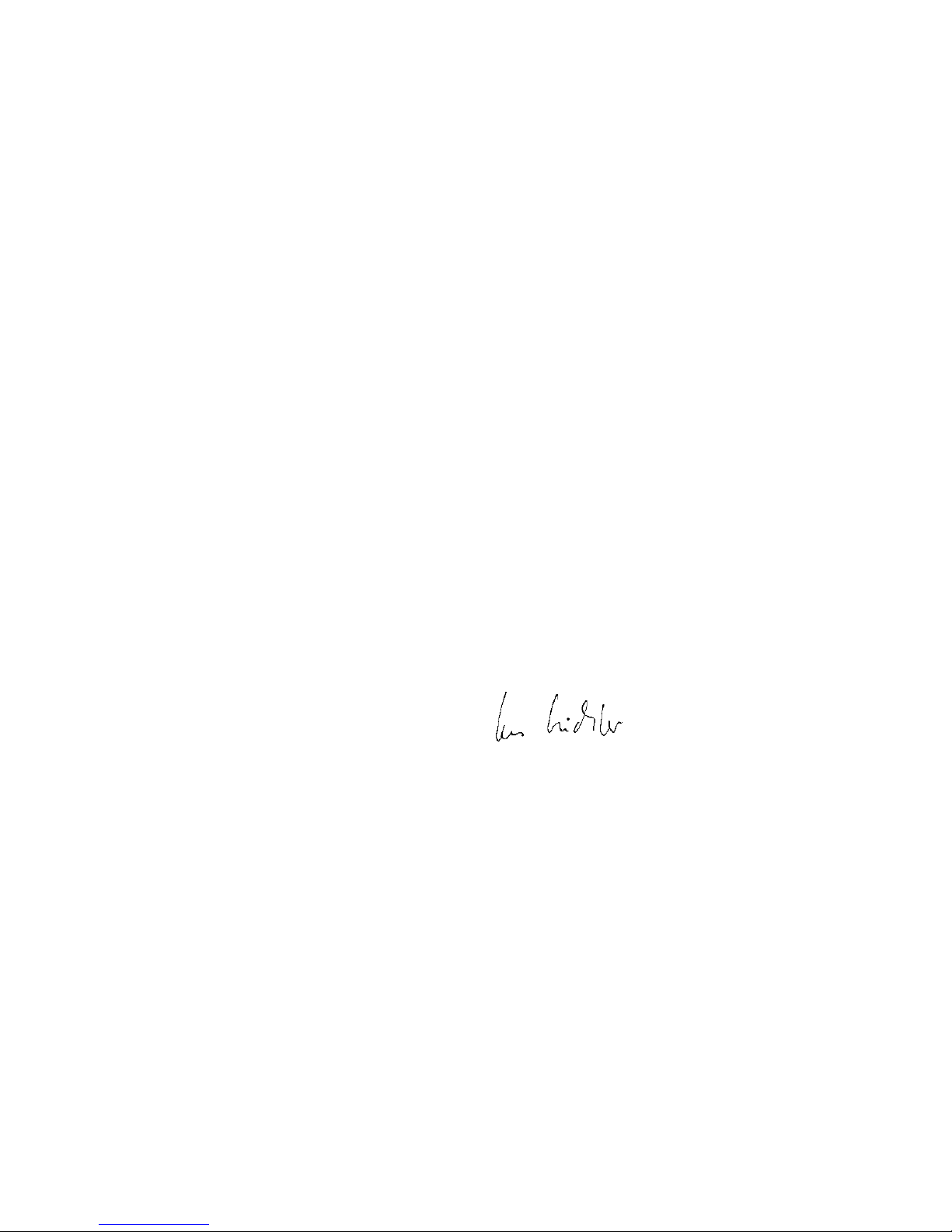
47
Mentor y el EasyGlider PRO. Si el despegue se lleva a cabo
desde el césped, necesitará equipar al Magister con un motor
potente. Por ejemplo, un Brushless de carcasa rotatoria con un
rendimiento de 300 Watios aproximadamente.
Para el remolque necesitará un cordel trenzado de 1 a 1,5 mm
Ø, de unos 20 m de largo. Al final se hace un lazo de una cuerda
de nylon de ø 0,5 mm (punto de ruptura) y se engancha en el
enganche del remolque (# 72 3470) del EasyGlider PRO.
Ilustr. 27
En el Mentor, se enganchará el otro extremo del cable de
remolque, usando un lazo, en el gancho. Ambos modelos se
alinearán contra el viento, uno tras otro. El cable de remolque
descansará sobre el estabilizador horizontal del Magister. El
remolcador carretea despacio hasta que el cable se tensa,
mientras el velero despega el remolcado permanece en el suelo,
despega pero no asciende, esperando al remolcador. Ambos
modelos ascienden al unísono (¡¡incluso en los virajes!!). Evite
sobrepasar al remolcador. Para desenganchar , hay que terminar
el vuelo ascendente – ponerlo todo en posición horizontal – dejar
de acelerar y soltar el velero.
Vuelo eléctrico
Con la versión eléctrica, el EasyGlider Electric, obtendrá lo
máximo en independencia. Con una sola carga de las baterías
y volando en llano, podrá realizar unas 4 trepadas a una altitud
razonable. En la ladera, no tendrá que preocuparse de los
“parones” (parones = cuando se ha de aterrizar en el valle porque
no se encuentran más ascendencias en la ladera).
Capacidades de vuelo / Rendimiento
¿Qué significa rendimiento en los veleros?
Los parámetros más importantes son la velocidad de perdida
y el ángulo de planeo. Con velocidad de perdida se describe
el descenso por segundo en el aire que rodea al modelo. La
velocidad de perdida dependen en primer lugar de la carga alar
(Peso / Superficie alar). El EasyGlider PRO posee valores
sobresalientes en este apartado, realmente mejores que los
modelos más habituales (solo 17g/dm²). Por eso, con una
ascendencia mínima (térmica) el modelo ganará altura. Además,
la velocidad de vuelo dependerá de la carga alar (cuanto más
liviano más lento). Así el modelo podrá realizar virajes cerrados,
algo especialmente útil volando en térmicas (Las térmicas son
muy fuertes cerca del suelo).
Y no menos importante: Para los que empiezan, un vuelo “lento”
ayuda a reflexionar y corregir pequeños errores en el control
del modelo.
Pero: „ ¡Donde hay luz, también hay sombras!“
El otro parámetro importante es el ángulo de planeo. Es la
relación entre la distancia (recta) recorrida y la perdida de altitud
del modelo, al recorrer esa distancia. El ángulo de planeo
aumenta con la carga alar y también con la velocidad de vuelo.
Es imprescindible aumentar la carga alar si se vuela con vientos
muy fuertes, o en vuelo acrobático.
También necesitará el ángulo de planeo volando en térmicas.
Será necesario salir de una térmica para volver a entrar en otra.
Necesitará lastre para aumentar la carga alar. Este lastre se
debería ubicar en las alas. Este lugar es el ideal para su
EasyGlider. Hay un tubo de fibra de vidrio en las alas. Su
diámetro interno es de 7,8 mm. Será muy difícil, y caro, encontrar
un tubo de plomo de estas medidas. Casualmente una barra
roscada M8 tiene esas mediadas. Puede encontrarlas a buen
precio en cualquier tienda. Tiene un diámetro de 7,7mm. En
algunos casos, le valdrá con media varilla. En este caso, debe
evitar que la barra se desplace lateralmente (p.Ej. introduzca
unos topes de madera de balsa en ambos extremos y ponga el
lastre en el centro).
Seguridad
La seguridad es el primer mandamiento del vuelo de modelos.
El seguro de responsabilidad civil es obligatorio. En caso de
que vaya a entrar en un club o una asociación puede realizar la
gestión del seguro por esa vía. Preste atención a las coberturas
del seguro.
Mantenga siempre los modelos y la emisora en perfecto estado.
Infórmese acerca de las técnicas de carga de las baterías que
vaya a utilizar. Utilice las medidas de seguridad más lógicas
que son ofrecidas. Infórmese en nuestro catálogo principal. Los
productos MULTIPLEX están realizados de la práctica para la
práctica por experimentados pilotos de radio control.
¡Vuele con sentido de la responsabilidad! Realizar pasadas por
encima de las cabezas de la gente no es una demostración de
saber hacer, los que realmente saben no necesitan hacer eso.
Informe de esta circunstancia, por el bien de todos, a los otros
pilotos. Vuele siempre de forma, que ni Usted ni otros entren en
peligro Recuerde que hasta el equipo de radio control más
puntero puede verse afectado por interferencias externas. Haber
estado exento de accidentes no es una garantía para el siguiente
minuto de vuelo.
Fascinación
Volar aeromodelos es, como pocos, un hobby fascinante para
ocupar nuestros ratos de ocio.
Disfrute conociendo, durante horas y en plena naturaleza su
EasyGlider PRO, sus asombrosas cualidades y su noble
comportamiento en vuelo.
Disfrute de una de las pocas disciplinas deportivas que conjuga
tecnología, el trabajo personal, la propia mejora, solo o con
amigos y posibilita el contacto con la naturaleza, lo que hoy en
día no suele ser muy habitual.
Nosotros, el equipo de Multiplex, le deseamos muchos éxitos
durante la construcción y posterior vuelo.
MULTIPLEX Modellsport GmbH &Co. KG
Produktbetreuung und Entwicklung
Klaus Michler
Page 48

48
Eje transver-
sal
E
Alerones
izquierda
Principios básicos tomando como ejemplo un avión
Un avión, o mejor dicho, un avión de radiocontrol, se manda con los timones por los siguientes 3 ejes: eje vertical, eje transversal y eje longitudinal.
El accionamiento del timón de profundidad supone una modificación de la posición de vuelo en el eje transversal. En el caso
de las desviaciones del timón de dirección, el modelo gira por el eje vertical. Si se quiere accionar un alerón, el modelo rola por
el eje longitudinal. Según las influencias del exterior, como p.ej. turbulencias que llevan al avión fuera de pista, el piloto debe
pilotar el avión de tal manera, que vuele hacía donde él quiere que vaya. Con la ayuda de una propulsión (Motor y hélice) se
elige la altura de vuelo. Un variador suele modificar las revoluciones del motor sin escalas. Es importante, que solamente el
tirar del timón de profundidad del modelo solo lo deja subir hasta que se haya alcanzado la velocidad mínima. Según la
potencia de la propulsión se pueden alcanzar distintos ángulos de paso.
El perfil del ala sustentadora
El ala sustentadora tiene un perfil abombado, en el que el aire
se desliza durante el vuelo. El aire por encima del ala
sustentadora recorre – en comparación con el aire en la parte
de abajo - un mayor recorrido en el mismo tiempo. Por ello,
en la parte superior del ala sustentadora se crea una presión
baja con una fuerza hacía arriba (empuje), que mantiene al
avión en el aire. Ilustr. A
El centro de gravedad
Para alcanzar características de vuelo estables, su modelo
tiene que estar en equilibrio en un punto determinada, al igual
que otros aviones también. Antes del primer vuelo es
imprescindible determinar este centro de gravedad.
La referencia se toma desde el borde de ataque del ala (cerca
del fuselaje). En este punto, el modelo debe equilibrase en
horizontal bien con la ayuda de los dedos o de una balanza
del centro de gravedad MPX # 69 3054. Ilustr. B
Si no se ha llegado aún al punto exacto del centro de gravedad,
este se puede alcanzar moviendo los componentes montados
(p. ej. batería del motor). Si aún no fuera suficiente se introduce
una cantidad determinada de plomo o masilla o bien en la
punta o bien en la cola del fuselaje. Si el avión se cae por la
cola, se meterá más peso en la punta – si se cae por la punta,
se hará lo mismo en la cola.
La DAA (Diferencia del ajuste del ángulo) indica la diferencia
en grados de ángulo, con el que la cola se ajusta respecto al
ala. Montando el ala y el estabilizador en el fuselaje sin dejar
ranuras y a conciencia, la DAA se mantiene de forma exacta.
Si ahora los dos ajustes (centro de gravedad y DAA) son
correctos, no se tendrán problemas ni a la hora de volar ni
durante el rodaje. Ilustr. C
Timones y desviaciones de los timones
Solo se pueden alcanzar características de vuelo seguras y
precisas, si los timones funcionan de forma suave, correcta y
calculadas desde el tamaño de las desviaciones. Las
desviaciones indicadas en las instrucciones de montaje se han
determinado durante unas pruebas y recomendamos que al
principio se guíe por estas medidas. Siempre hay tiempo para
ajustarlas a su forma de volar.
Funciones de mando en la emisora
En la emisora de radiocontrol hay dos palancas de mando,
que accionan los servos y los timones del modelo.
La asignación de estas funciones están indicadas en el modo
A – otras asignaciones también son posibles.
Con la emisora se accionan los siguientes timones
El timón de dirección (izquierda/derecha) Ilustr. D
El timón de profundidad (arriba/abajo) Ilustr. E
Alerones (izquierda/derecha) Ilustr. F
El estrangulador del motor (motor off/on) Ilustr. G
La palanca del estrangulador del motor no debe volver por si
sola a la posición neutral. Es encastrable durante todo su
recorrido. Como funciona el ajuste se puede leer en las
instrucciones de montaje de la emisora.
Cono
Eje longitudinal
Eje vertical
Fuselaje
Capottina
Ala izquierda
timón de
direction
timón de
profunidad
Empenaje del
timón de
dirección
Empenaje del
timón de
profundidad
Ala derecha
Alerones
derecha
Page 49
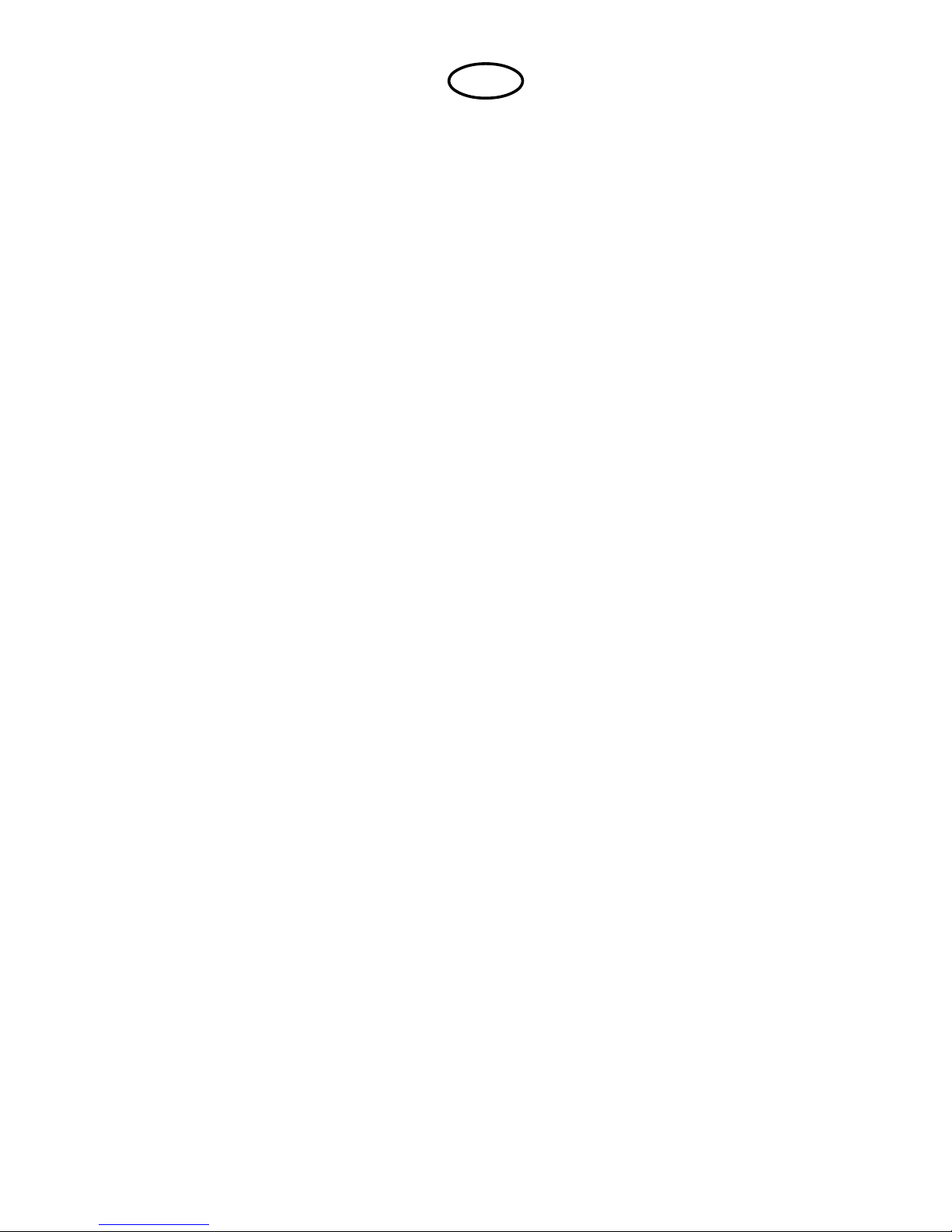
49
Lista de piezas
BK EasyGliderPRO + electric BlueEdition
Nº. Cantidad Denominación Material Medidas
1 1 Manual de instrucciones papel DIN-A4
2 1 Pliego de decoración adhesivo multicolor 350 x 1.000mm
3 1 Mitad de fuselaje izquierda Elapor espumado Pieza terminada
4 1 Mitad de fuselaje derecha Elapor espumado Pieza terminada
5 1 Morro velero EPP espumado Pieza terminada
7 1 Cubierta de cabina Elapor espumado Pieza terminada
8 1 Ala izquierda Elapor espumado Pieza terminada
9 1 Ala derecha Elapor espumado Pieza terminada
10 1 Revestimiento de larguero izquierdo Elapor espumado Pieza terminada
11 1 Revestimiento de larguero derecho Elapor espumado Pieza terminada
12 1 Cola Elapor espumado Pieza terminada
13 1 Deriva Elapor espumado Pieza terminada
Piezas pequeñas
20 2 Cinta adhesiva ganchos plástico 25 x 60 mm
21 2 Cinta adhesiva velours plástico 25 x 60 mm
22 2 Cierre de la cabina pinza de cierre plástico inyectado Pieza terminada
23 2 Cierre de la cabina perno de cierre plástico inyectado Pieza terminada
24 4 Escuadra adhesiva plástico inyectado Pieza terminada
25 4 Conexión del varillaje metal Pieza terminada Ø 6mm
26 4 Disco en U metal M2
27 4 Tuerca metal M2
28 4 Pasador hexagonal de rosca metal M3 x 3mm
29 1 Llave hexagonal metal SW 1,5
30 2 Varillaje de los alerones con Z metal Ø 1 x 80mm
31 1 Bisagra plástico inyectado Pieza terminada
32 1 Gancho para el despegue catapultado plástico inyectado Pieza terminada
33 2 Contrapeso Acero bola Ø13mm
34 1 Soporte motor plástico inyectado Pieza terminada
35 1 Tirador de la cabina plástico inyectado Pieza terminada
36 2 Soporte del cable plástico inyectado Pieza terminada
37 2 Cuaderna longitudinal de la cabina plástico inyectado Pieza terminada
Juego de alambres
40 1 Conector de largueros tubo de fibra de vidrio Ø 10 x 8 x 1.000mm
41 1 Alambre de acero para TP con Z metal Ø 0,8 x 875mm
42 1 Alambre de acero para TD con Z metal Ø 0,8 x 875mm
43 1 Tubo exterior de la transmisión TP plástico Ø 3/2 x 785mm
44 1 Tubo exterior de la transmisión TD plástico Ø 3/2 x 785mm
45 1 Tubo interior de la transmisión TP plástico Ø 2/1 x 850mm
46 1 Tubo interior de la transmisión TD plástico Ø 2/1 x 850mm
47 1 Tubo exterior de la transmisión TP antena plástico Ø 3/2 x 785mm
Repuestos (ver también página 50/51 ; por favor, encargar en su tienda especializada)
Pliego de adhesivos 72 4236
Pliego de adhesivos electric BlueEdition 72 4239
Mitades de fuselaje + transmisiones 22 4150
Cubierta de cabina 22 4151
Alas 22 4159
Juego de piezas pequeñas 22 4152
Conector de larguero 72 3190
Cierre de la cabina
(cierre de la cubierta de la cabina) 72 5136
Juego de empenajes 22 4160
E
Page 50

50
Ersatzteile (bitte bei Ihrem Fachhändler bestellen)
Replacement parts (please order from your model shop)
Pièces de rechanges (S.V.P. à ne commander que chez votre revendeur)
Parti di ricambio (da ordinare presso il rivenditore)
Repuestos (por favor, diríjase a su distribuidor)
PRO
# 22 4159
Tragflächen
Wing panels
Ailes
Ali
Alas
# 22 4160
Leitwerkssatz
Tail set
Kit de gouvernes
Piani di coda
Timones
# 22 4152
Kleinteilesatz
Small items set
Petit nécessaire
Minuteria
Piezas pequeñas
# 72 3190
Holmverbinder
Wing joiner
Clé d’aile
Baionetta
Larguero (bayoneta)
Page 51
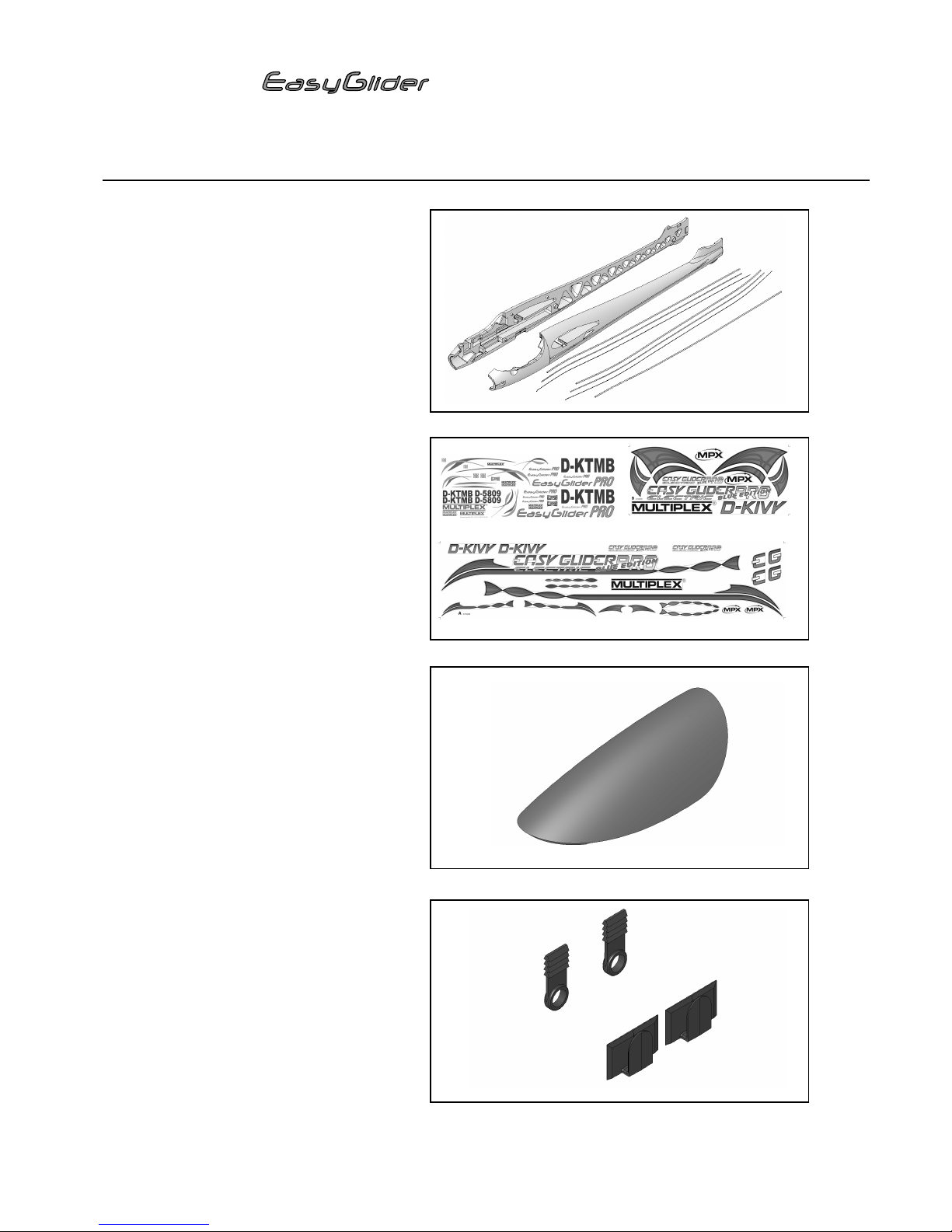
51
# 22 4150
Rumpfhälften + Bowdenzüge
Fuselage shells + snakes
Moitié de fuselage + tringlerie
Semigusci fusoliera + bowden
Fuselaje + transmisiones bowden
# 72 4236 / # 72 4239 (BlueEdition A+B)
Dekorbogen
Decal sheet
Planche de décoration
Decals
Lámina decorativa
# 22 4151
Kabinenhaube
Canopy
Verrière
Capottina
Cabina
# 72 5136
Canopy-Lock
Kabinenhaubenverschluss
fermeture de verrière
chiusura capottina
Cierre de cabina
Ersatzteile (bitte bei Ihrem Fachhändler bestellen)
Replacement parts (please order from your model shop)
Pièces de rechanges (S.V.P. à ne commander que chez votre revendeur)
Parti di ricambio (da ordinare presso il rivenditore)
Repuestos (por favor, diríjase a su distribuidor)
PRO
B
A
Page 52

52
MUL TIPLEX Modellsport GmbH & Co.KG W estliche Gewerbestrasse 1 D-75015 Bretten Gölshausen www .multiplex-rc.de
 Loading...