

Page 1
Baukasten / kit # 21 4235
D
F
GB
I
E
© Copyright by MULTIPLEX 2008 Version 1.0
Bauanleitung 3 ... 9
Notice de construction 10 ... 16
Building instr uctions 17 ... 27
Instruzioni di montaggio 28 ... 34
Instrucciones de montaje 35 ... 41
Ersatzteile
Replacement parts
Pièces de rechanges
Parti di ricambio
Repuestos
42 ... 43
1
Page 2

D
Sicherheitshinweise
Prüfen Sie vor jedem Start den festen Sitz des Motors und der Luf tschraube - insbesondere nach dem Transport, härteren Landungen
sowie Abstürzen. Prüfen Sie ebenfalls vor jedem S tart den festen Sitz und die richtige Position der T ragflächen auf dem Rumpf.
Akku erst einstecken, wenn Ihr Sender eingeschaltet ist und Sie sicher sind, daß das Bedienelement für die Motorsteuerung auf "AUS"
steht.
Im startbereiten Zustand nicht in den Bereich der Luftschraube greifen.
Vorsicht in der Luf tschraubendrehebene - auch Zuschauer zur Seite bitten!
Zwischen den Flügen die Motortemperatur durch vorsichtige Fingerprobe prüfen und
vor einem Neustart den Motor ausreichend abkühlen lassen. Die Temperatur ist richtig, wenn Sie den Motor problemlos berühren
können. Insbesondere bei hohen Außentemperaturen kann dieses bis zu 15 Minuten dauern.
Denken Sie immer daran: Niemals auf Personen und Tiere zufliegen.
F
Conseils de sécurité
Avant chaque décollage, vérifiez la fixation du moteur et de l'hélice, notamment après le transport, après les atterrissages violents et
après un “Crash”. Vérifiez également, avant chaque décollage la fixation ainsi que le positionnement de l’aile par rapport au fuselage.
Ne branchez l’accu de propulsion que si vous êtes sûr que votre émetteur est allumé et que l’élément de commande moteur est en
position “ARRET”.
Ne mettez pas vos doigts dans l’hélice! Attention à la mise en marche, demandez également aux spect ateurs de reculer.
Entre deux vols, vérifiez en posant un doigt dessus, la température du moteur, laissezle refroidir suffisamment avant le prochain
décollage. La température est correcte si vous pouvez maintenir votre doigt ou votre main sur le moteur. Le temps de refroidissement
peut varier jusqu’à 15 minutes s’il fait particulièrement chaud.
Pensez-y toujours: ne volez jamais vers ou au-dessus des personnes ou des animaux.
GB
E
Safety notes
Before every flight check that the motor and propeller are in place and secure - especially after transporting the model, and after hard
landings and crashes. Check also that the wing is correctly located and firmly secured on the fuselage before each flight.
Don’t plug in the battery until you have switched on the transmitter, and you are sure that the motor control on the transmitter is set to
“OFF”.
When the model is switched on, ready to fly , take care not to touch the propeller . Keep well clear of the propeller disc too, and ask
spectators to stay back.
Allow the motor to cool down after each flight. You can check this by carefully touching the motor case with your finger. The
temperature is correct when you can hold your finger on the case without any problem. On hot days this may take up to 15 minutes.
Please keep in mind at all times: don’t fly towards people or animals.
I
Note di sicurezza
Prima di ogni decollo controllare che il motore e la eliche siano fissati stabilmente - specialmente dopo il trasporto, atterraggi duri e se il
modello è precipitato. Controllare prima del decollo anche il fissaggio e la posizione corretta delle ali sulla fusoliera.
Collegare la batteria solo quando la radio è inserita ed il comando del motore è sicuramente in posizione ”SPENTO”.
Prima del decollo non avvicinarsi al campo di rotazione della eliche. Attenzione alla eliche in movimento - pregare che eventuali spettatori
si portino alla dovuta distanza di sicurezza!
Tra un volo e l’altro controllare cautamente con le dita la temperatura del motore e farli raffreddare sufficientemente prima di ogni nuovo
decollo. La temperatura è giusta se si possono toccare senza problemi. Specialmente con una temperatura esterna alta questo può
durare fino a 15 minuti.
Fare attenzione: Non volare mai nella direzione di persone ed animali.
Advertencias de seguridad
Compruebe antes de cada despegue que el motor y la hélice estén fuertemente sujetados, sobretodo después de haberlo transportado,
de aterrizajes más fuertes así como después de una caída. Compruebe igualmente antes de cada despegue que las alas estén bien
sujetas y bien colocadas en el fuselaje.
Conectar la batería, cuando la emisora esté encendida y Usted esté seguro que el elemento de mando para el motor esté en ”OFF”.
No meter la mano en la zona inmediata a la hélice cuando el avión esté a punto de despegar. ¡Cuidado con la zona de la hélice! ¡Pedir a
los espectadores que se aparten!
Entre los vuelos hay que comprobar cuidadosamente la temperatura del motor con el dedo y dejar que el motor se enfríe antes de volver
a despegar. La temperatura es correcta, si puede tocar el motor sin problemas. Sobretodo en el caso de temperaturas del ambiente muy
altas, esto puede tardar unos 15 minutos.
Recuerde: No volar nunca hacía personas o animales.
2
Page 3

GB
Examine your kit carefully!
MULTIPLEX model kit s are subject to const ant quality checks throughout the production process, and we sincerely hope that you
are completely satisfied with the contents of your kit. However, we do ask you to check all the parts (referring to the Parts List)
before you start construction, as we cannot exchange components which you have already modified. If you find any part is not
acceptable, we will readily correct or exchange it once we have examined it. Just send the component to our Model Department;
please be sure to include the purchase receipt and a brief description of the fault.
We are constantly working on improving our models, and for this reason we must reserve the right to change the kit contents in
terms of shape or dimensions of parts, technology, materials and fittings, without prior notification. Please understand that we
cannot entertain claims against us if the kit contents do not agree in every respect with the instructions and the illustrations.
Caution!
Radio-controlled models, and especially model aircraft, are by no means playthings. Building and operating them safely
requires a certain level of technical competence and manual skill, together with discipline and a responsible attitude at the
flying field. Errors and carelessness in building and flying the model can result in serious personal injury and damage to
property. Since we, as manufacturers, have no control over the construction, maintenance and operation of our product s,
we are obliged to take this opportunity to point out these hazards and to emphasise your personal responsibility .
Additional items required for the EasyCub:
Airborne radio control components:
MULTIPLEX RX-7-Synth IPD receiver 35 MHz A band Order No. 5 5880
alternatively: 40 / 41 MHz band Order No. 5 5882
or MULTIPLEX RX-6-Synth light 35 MHz A / B-band Order No. 5 5876
2 x MULTIPLEX T iny S servo elevator, rudder Order No. 6 5121
or 2 x MULTIPLEX T iny MG servo elevator, rudder Order No. 6 5122
# 21 4235
Power set:
MULTIPLEX EasyCub power set Order No. 33 2637
Motor: Himax C 2816-1220; speed controller: BL 27 II; 10 x 5” propeller, propeller driver
Flight battery:
MULTIPLEX Li-Batt eco 2/1-2000 flight battery Order No. 15 7230
or MULTIPLEX Li-Batt BX 2/1-2100 flight battery Order No. 15 7130
Tools:
Scissors, balsa knife, combination pliers, screwdriver.
Specification:
Wingspan: 1400 mm
Fuselage length: 980 mm
All-up weight with Li-Batt BX 2/1-2100 approx.: 850 g
Wing area: 36.5 dm²
Wing loading (FAI) approx.: 23 g/dm²
RC functions: Rudder, elevator, throttle
Note: please remove the illustration pages from the centre of the instructions.
Important note
This model is not made of styrofoam™, and it is not possible to glue the material using white glue, polyurethane or
epoxy; these adhesives only produce a superficial bond which simply gives way when stressed. Please use mediumviscosity cyano-acrylate glue exclusively, preferably our Zacki-ELAPOR®, # 59 2727 - the cyano glue optimised
specifically for ELAPOR® particle foam.
If you use Zacki-ELAPOR® you will find that you do not need cyano kicker or activator for most joints. However, if you
wish to use a different adhesive, and are therefore obliged to use kicker / activator spray, we recommend that you
apply the material in the open air to avoid health problems.
Please take care when working with any type of cyano-acrylate (“cyano”, “CA”) adhesive, as they can cure in
seconds. Don’t allow the glue to contact your fingers or any other part of your body. Always wear goggles to protect
your eyes!
Keep out of the reach of children!
17
Page 4

1. Before assembling the model
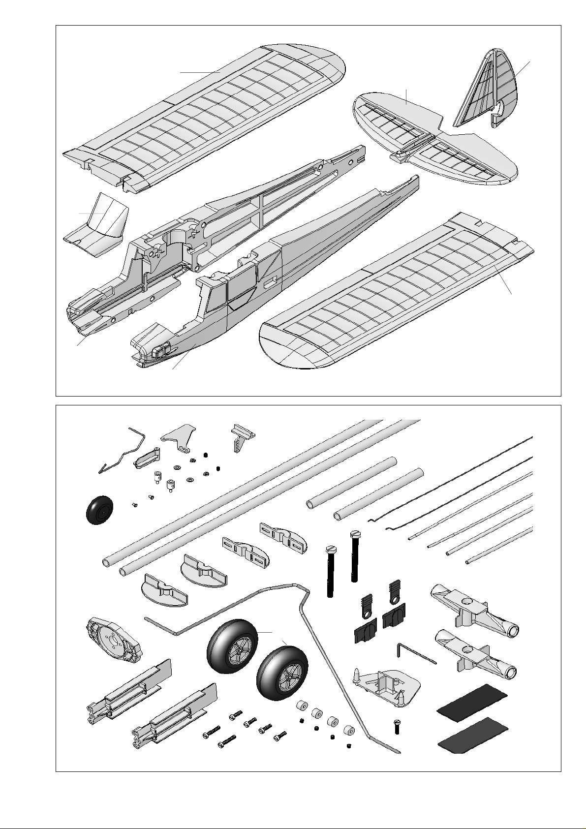
Please check the contents of your kit before you start working
on it.
You will find Figs. 1 + 2 and the Parts List helpful here.
2. The fuselage
The first step is to glue the canopy latches 22 and the motor
mounts 37 to both fuselage shells.
Fig. 3
3. Installing the servos
Trial-fit the “rudder” and “elevator” servos in the fuselage shells
3 + 4, and secure them with a drop of glue at each mounting
lug. Fix the servo leads in place with paper masking tape so
that the leads and plugs cannot cause damage, and do not
get in the way when the fuselage shells are joined
subsequently.
Fig. 4
4. Control snakes
Prepare the snakes 54 / 56 and 55 / 57 as follows: cut the outer
and inner sleeves to length if necessary, and slip the steel
pushrods 52 / 53 into them. Connect the pre-formed end of the
pushrods to the servos, position the snakes carefully and glue
them to the fuselage. Note that the pre-formed pushrod ends
should be connected to the innermost holes in the servo output
levers. Lay the fuselage shells down flat when gluing the
snakes in place, otherwise there is a chance of distorting the
fuselage.
Figs. 4 - 6
5. Preparing the wing screw supports
Snap the wing screw support components 33 + 34 together
and glue the joints; use a pair of flat-nose pliers to join them if
necessary . Glue the prepared wing screw supports in the righthand fuselage shell as shown.
Fig. 7
6. Joining the fuselage shells
Join the fuselage shells 3 / 4 “dry” (without glue) initially, and
check that everything fits properly before gluing the shells
together permanently. Check that the fuselage is perfectly
straight before allowing the glue to set hard.
Fig. 7
end over at 90° as close to part 35 as possible, as shown in
Fig. 10.
Glue the rudder horn 35 in the rudder, but apply cyano to the
underside only. Allow the glue to set hard, then cut a slot about
1.5 mm deep for the tailwheel unit above the horn.
Wipe away excess adhesive if necessary. Position the wire
tailwheel unit 76 over the horn 35, align the parts and glue
them together using plenty of cyano. Allow the glue to cure,
then attach the swivel pushrod connector to the horn. Secure
the retaining nut with a drop of paint or glue. Fig. 11
Fit the tailwheel 77 on the axle: first push one metal wheel
retainer sleeve 78 on the wire, then the wheel, followed by the
second retainer sleeve. Secure each sleeve 78 with a drop of
cyano.
Fig. 12
10. Gluing the fin to the fuselage
Trial-fit the prepared fin in the slots in the fuselage and tailplane,
and glue it in place.
Fig. 13
11. Main undercarriage
Prepare the main undercarriage 70 as follows:
Fit socket-head grubscrews 73 in the four wheel collets 72,
and secure the wheels 71 on the undercarriage by fitting a
collet on each side of each wheel. Check that the wheels rotate
freely, then tighten the grubscrews. Fig. 15
The plastic undercarriage bracket 74 can now be installed in
the fuselage: first press it into position, then apply glue all
round it. Fig. 14
Allow the undercarriage 70 to snap into position in the bracket,
then fit the retainer screw 75 to secure it.
Fig. 15
12. The wings
The wing panels 6 / 7 should not be glued together!
Trial-fit the wing spars 50 / 51 and the spar holders 30 / 31 as
shown in the illustration.
7. Preparing the pushrod connector
Fit the swivel pushrod connector 25 for the elevator 8 in the
outer hole in the elevator horn 24, and secure it with the washer 26 and the nut 27. Caution: be sure to fit the connector on
the correct side of the horn (see illustration). Tighten the nut
carefully: the pushrod connector must swivel smoothly, but
without undue slop. Apply a tiny drop of cyano or paint to the
threads (on the point of a pin) to prevent the nut working loose.
Fit the socket-head grubscrew 28 on the allen key 29, and use
it to fit the screw loosely in the pushrod connector 25. Glue the
horn 24 in the elevator 8 with the row of holes facing forward.
Fig. 8
8. Gluing the tailplane to the fuselage
Place the tailplane on the fuselage and check that it can be
positioned and aligned correctly; carry out any minor trimming
required. Glue the tailplane to the fuselage and hold it in
position while the adhesive hardens.
Fig. 9
9. Fin and tailwheel
Fit the wire tailwheel unit 76 through the glue-fitting tailwheel
bush 36, then through the glue-fitting rudder horn 35. Bend the
18
Note: the front spar holder 30 is taller than the rear holder 31.
When you are sure that everything fits properly, glue the spars
50 / 51 and the spar holders 30 / 31 in the right-hand wing
panel only. Fig. 16
Now insert the second pair of spars in the free end of the spar
holders (do not use glue!). Slide the left wing onto the spars
and holders and check that they fit correctly. Apply glue to the
spar channel in the left wing and position it accurately on the
spars. Fig. 17
If you have done everything correctly, you will now be able to
part the wing panels in the centre once the glue has set hard.
13. Trial assembly
The wings are held on the fuselage using the plastic screws
32. The locating blocks moulded into the underside of the
wing prevents the wing slipping off the fuselage or out of
position.
Fig. 18
14. Power set:
The model is designed to be fitted with the MULTIPLEX
Page 5

EasyCub Power Set, Order No. 33 2637.
The set consists of a Himax C 2816-1220 motor, a BL 27/II
speed controller, a 10 x 5” propeller and a propeller driver.
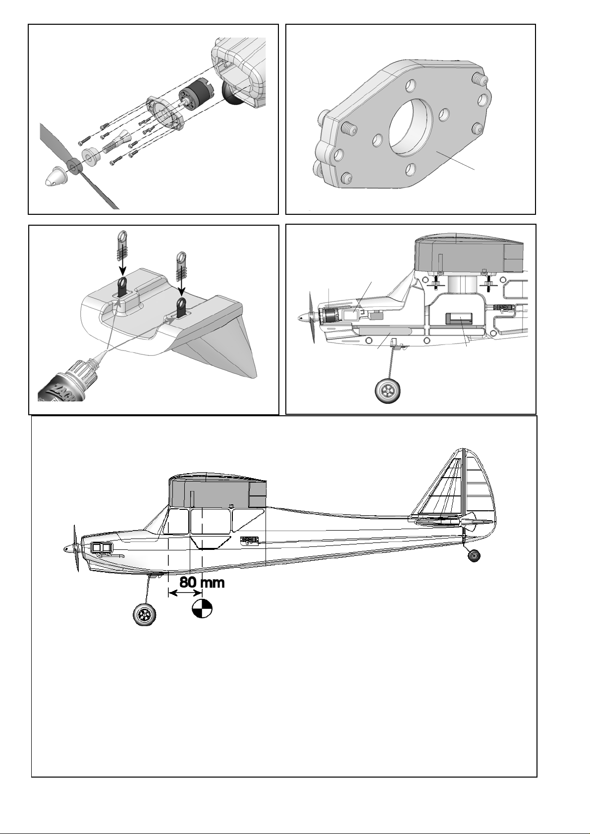
15. Attaching the motor bulkhead to the motor mount
The motor sidethrust and downthrust can be adjusted using
the motor mounts 37 and the motor bulkhead 38. Fitting the
four adjustor screws 39 flush installs the mount asymmetrically,
giving maximum sidethrust and no downthrust. The basic
position for the EasyCub is set as follows (note that we are
looking at the rear (!) of the motor bulkhead). Fig. 20
Upper left adjustor screw 1 mm = approx. two
turns
Upper right adjustor screw 1 mm = approx. two
turns
Lower left adjustor screw 1 mm = approx. two
turns
Lower right adjustor screw 1 mm = approx. two
turns
The screws should project by the values stated above. The
settings may require fine-tuning during the test-flying
programme.
16. Installing the motor
Attach the motor to the motor bulkhead 38 using the retaining
screws included in the power set. Install the motor as shown
in Fig. 19.
17. Installing the canopy latch tongues
The canopy 5 is first slid into the fuselage towards the wing,
and only then folded down at the front. Temporarily insert the
two latch tongues 23 in the canopy, and position them as
shown in the illustration. Apply high-viscosity (thick) cyano to
the textured surfaces, then fit the latch tongues into the slots in
the canopy. Place the canopy on the fuselage, and allow the
latch tongues to engage in the latches 22. Check immediately
that the canopy is correctly aligned with the fuselage. Wait for
about one minute, then carefully open the canopy again. If
necessary, apply more glue to the latch tongues to reinforce
the joints.
Fig. 21
the wrong direction, swap over any two of the motor connections
- never swap over the battery connections.
Caution: there is a serious risk of injury in the area around
the propeller!
19. Deploying the aerial on the underside of the fuselage
The wire receiver aerial should be routed through a hole in the
underside of the fuselage and deployed towards the tail.
You will need to pierce a hole in the fuselage from the outside
before threading the aerial through it from the inside. Tape the
aerial to the fuselage. If the aerial is longer than the fuselage,
simply allow the excess length to trail freely.
20. Setting the control surface travels
The control surface travels must be set correctly in order to
obtain a balanced control response from the model.
Elevator travels:
up (stick back towards you) 15 mm
down (stick away from you) 12 mm
Rudder travel to left and right: 15 mm each way
Note that the stated travels are measured at the widest point of
the control surface.
21. Gilding the lily - applying the decals
The kit is supplied with a multi-colour decal sheet 2. Cut out
the individual name placards and emblems and apply them to
the model in the position shown in the kit box illustration, or in
an arrangement which you find pleasing. The decals cannot
be re-positioned once applied, so place them carefully!
22. Balancing
Like any other aircraft, the EasyCub must be balanced at a
particular point in order to achieve stable flying characteristics.
Assemble your model ready to fly, and install the flight battery.
The Centre of Gravity (CG) should be at a position 80 mm aft
of the root leading edge, i.e. at the fuselage sides. Mark this
point on both sides of the fuselage.
18. Installing the flight battery and receiver
The space for the flight battery is under the canopy, extending
back under the wing saddle. The battery is held in place using
the Velcro tape 20 / 21.
The speed controller fits on the fuselage side on one side of
the battery. The receiver should be installed below the wing
saddle, again using the Velcro tape 20 / 21.
Fig. 22
If the controller is connected to the motor, do not connect
the battery to the speed controller without first switching
the transmitter on and ensuring that the throttle control is at
the “OFF” position.
Connect the servo leads to the receiver. Switch the transmitter
on, connect the flight battery (installed in the model) to the
speed controller, and connect the speed controller to the
receiver.
Now switch the motor on briefly by advancing the throttle stick,
and check that the propeller spins in the correct direction. When
test-running the motor be sure to hold the model securely, and
remove all loose, light objects before and behind the model
before the propeller does the job for you. If the motor rotates in
Support the model at this position on two fingertips, and it
should balance level. If not, you can move the flight battery
forward or aft to correct the balance point. Once the correct
position is found, mark the location of the flight pack inside the
model to ensure that it is always replaced in the same position.
The CG location is not critical - 10 mm forward or aft of the
stated position presents no problems.
Fig. 23
23. Preparing for the first flight
For the first flight wait for a day with as little breeze as possible.
The early evening is often a good time.
Be sure to carry out a range check before the first flight!
Just before the flight, charge up the transmitter battery and the
flight pack using the recommended procedures. Ensure that
“your” channel is not already in use
transmitter.
Ask your assistant to walk away from the model, holding the
transmitter. The transmitter aerial should be fitted but
completely collapsed.
Your assistant should operate one of the functions constantly
before you switch on the
19
Page 6

while you watch the servos. The non-controlled servo should
stay motionless up to a range of about 60 m, while the controlled
one should follow the stick movements smoothly and without
any delay. Please note that this check can only give reliable
results if the radio band is clear of interference, and if no other
radio control transmitters are in use - even on different channels.
If the range check is successful, repeat it with the motor running.
There should only be a very slight reduction in effective radio
range with the motor turning.
If you are not sure about anything, please don’t risk a flight.
Send the whole system (including battery, switch harness and
servos) to the Service Department of your RC system
manufacturer and ask them to check it.
fuselage level. Use the controls to hold the model in a steady,
gentle climb - remember to keep the rate of ascent shallow
and the airspeed high!
Allow the aeroplane to climb to a safe height, then adjust the
trims on the transmitter until it flies in a perfectly straight line
“hands off”.
While the model is still at a safe altitude, throttle back and try
out the controls on the glide. Carry out a “dry run” landing
approach at a safe height so that you are prepared for the real
landing when the battery runs flat.
Don’t try any tight turns at first, and especially not on the landing
approach at low altitude. It is always better to land safely at
some distance from you, than to force the model back to your
feet and risk a heavy landing.
The first flight ...
The EasyCub should always be launched exactly into any wind.
If you are a beginner to model flying we strongly recommend
that you ask an experienced model pilot to help you for the
first few flights.
24. T aking off from a hard strip
If you have access to a hard landing strip, a ground take-off is
the safest option.
Apply full up-elevator initially (to keep the tail down) and
accelerate gradually, using the rudder to keep the model on a
straight track.
Apply full-throttle to continue accelerating, gradually returning
the elevator stick to neutral. The tail will now rise; when the
model reaches flying speed apply gentle but deliberate upelevator to lift off. Allow the aeroplane to climb at a steady, fairly
shallow angle, taking care to keep the airspeed up!
From a closely mown grass strip a ground take-off works just
like on a hard strip, but the ground-roll will be longer. If you do
not have access to a runway of any kind, a hand-launch works
fine.
Caution: if your assistant is an experienced hand-launcher
then you can be confident of success; if not, watch out!
25. Hand-launching
Please don’t try unpowered test-glides with this model - the
result is invariably a damaged airframe. The EasyCub should
always be hand-launched with the motor running at full-throttle,
and always pointing directly into wind.
Ask an experienced modeller to hand-launch your aircraft for
you: he should run forward for two or three paces, then give the
machine a powerful straight launch, with the wings and
26. Safety
Safety is the First Commandment when flying any model
aircraft. Third party insurance should be considered a basic
essential. If you join a model club suitable cover will usually be
available through the organisation. It is your personal
responsibility to ensure that your insurance is adequate.
Make it your job to keep your models and your radio control
system in perfect order at all times. Check the correct charging
procedure for the batteries you are using. Make use of all sensible safety systems and precautions which are advised for
your system. An excellent source of practical accessories is
the MULTIPLEX main cat alogue, as our product s are designed
and manufactured exclusively by practising modellers for other
practising modellers.
Always fly with a responsible attitude. You may think that flying
low over other people’s heads is proof of your piloting skill;
others know better. The real expert does not need to prove
himself in such childish ways. Let other pilots know that this is
what you think too. Always fly in such a way that you do not
endanger yourself or others. Bear in mind that even the best
RC system in the world is subject to outside interference. No
matter how many years of accident-free flying you have under
your belt, you have no idea what will happen in the next minute.
We - the MULTIPLEX team - hope you have many hours of
pleasure building and flying your new model.
MULTIPLEX Modellsport GmbH & Co. KG
Product development and maintenance
20
Klaus Michler
Page 7
9
6
5
8
7
4
77
50
76
36
78
3
35
24
51
28
27
26
25
32
34
23
33
71
70
22
29
Abb. 1
52
53
56
57
54
55
30
38
37
2x 40
4x 39
4x72
4x73
75
74
31
3x 20
3x 21
Abb. 2
21
Page 8

22
4
54 56 52
37
Abb. 3
4
52
4
56
54
Abb. 4
3
53 57 55
2x 33/34
Abb. 5
4
3
27 26 24 25 28
Abb. 6
8
Abb. 7
Abb.8
8
22
4
35
36
3
Abb. 9
76
Abb.10
Page 9

4
28
25
35
36
78
78
26
27
76
Abb. 11
9
8
Abb. 13
77
74
3
4
76
Abb. 12
Abb. 14
72
71
Abb. 15
50
51
73
70
75
50
7
32
7
6
51
Abb. 16
30
31
Abb. 17
6
Abb. 18
23
Page 10
Antriebsatz / Powerset # 33 2637
38
23
Abb. 19
5
Abb. 21
Motor
ESC
Akku
Abb. 20
RX
Abb. 22
24
Abb. 23
Page 11

EasyCub Parts List
Part No. Description Material Dimensions
No. off
1 1 Building instructions Paper, 80 g/m² A4
2 1 Decal set Printed adhesive film 500 x 700 mm
3 1 L.H. fuselage shell Moulded Elapor foam Ready made
4 1 R.H. fuselage shell Moulded Elapor foam Ready made
5 1 Canopy Moulded Elapor foam Ready made
6 1 L.H. wing panel Moulded Elapor foam Ready made
7 1 R.H. wing panel Moulded Elapor foam Ready made
8 1 Tailplane Moulded Elapor foam Ready made
9 1 Fin Moulded Elapor foam Ready made
70 1 Main undercarriage unit Spring steel 2.5 mm Ø, ready made
Small items
20 3 Velcro tape, “mushroom” Plastic 25 x 60 mm
21 3 Velcro tape, “felt” Plastic 25 x 60 mm
22 2 Canopy latch Inj. moulded plastic Ready made
23 2 Canopy latch tongue Inj. moulded plastic Ready made
24 1 Glue-fitting control surface horn Inj. moulded plastic Ready made
25 2 Swivel pushrod connector Metal Ready made, 6 mm Ø
26 2 Washer Metal M2
27 2 Nut Metal M2
28 2 Socket-head grubscrew Metal M3 x 3 mm
29 1 Allen key Metal 1.5 mm A/F
30 1 Front spar holder, “tall” Inj. moulded plastic Ready made
31 1 Rear spar holder, “low”` Inj. moulded plastic Ready made
32 2 Screw Inj. moulded plastic M5 x 50 mm
33 2 Wing screw support, part A Inj. moulded plastic Ready made, M5
34 2 Wing screw support, part B Inj. moulded plastic Ready made, M5
35 1 Glue-fitting horn, tailskid Inj. moulded plastic Ready made
36 1 Glue-fitting tailskid bush Inj. moulded plastic Ready made
37 2 Motor mount Inj. moulded plastic Ready made
38 1 Motor bulkhead Inj. moulded plastic Ready made
39 4 Motor bulkhead adjustor screw Metal M3 x 10 mm
40 2 Motor bulkhead mounting screw Metal M3 x 16 mm
Wire and rod
50 2 Tubular wing spar GRP tube 8 Ø x 6 Ø x 400 mm
51 2 Tubular wing spar GRP tube 8 Ø x 6 Ø x 100 mm
52 2 Pre-formed elevator pushrod Metal 0.8 Ø x 510 mm
53 2 Pre-formed rudder pushrod Metal 0.8 Ø x 510 mm
54 1 Elevator snake outer sleeve Plastic 3 Ø x 2 Ø x 480 mm
55 1 Rudder snake outer sleeve Plastic 3 Ø x 2 Ø x 480 mm
56 1 Elevator snake inner sleeve Plastic 2 Ø x 1 Ø x 500 mm
57 1 Rudder snake inner sleeve Plastic 2 Ø x 1 Ø x 500 mm
Undercarriage set
71 2 Lightweight main wheel Plastic 53 Ø
72 4 Wheel collet Metal 2.7 Ø x 8 Ø x 5 mm
73 4 Socket-head grubscrew Metal M3 x 3 mm
74 1 Undercarriage bracket Plastic Ready made
75 1 Undercarriage retainer screw Metal M3 x 12 mm
76 1 Tailwheel unit Metal 1.3 mm Ø
77 1 Lightweight tailwheel Foam rubber 26 mm Ø
78 2 Tailwheel retainer sleeve Tubular rivet 2 Ø x 0.2 x 3 mm
25
Page 12
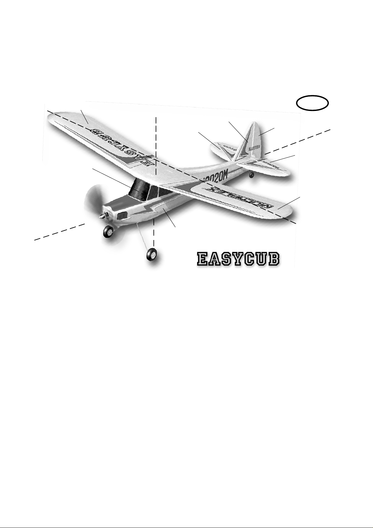
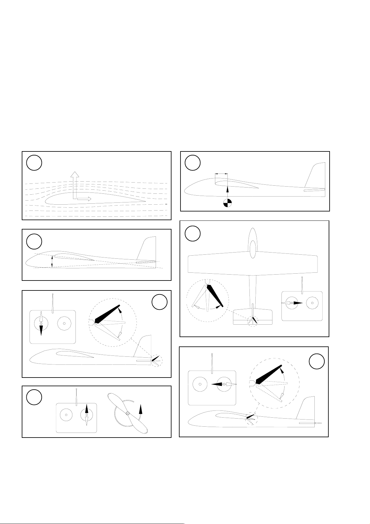
The basics of flying - using a model aircraft as an example
Any aircraft - full-size or model - can be controlled around three primary axes: the vertical (yaw) axis, the lateral (pitch) axis and the
longitudinal (roll) axis. Operating the elevator produces a change in the model’s flight attitude around the lateral axis (nose up
or down). External influences such as air turbulence constantly tend to divert the model from its intended flight path, and it is the
pilot’s job to control the model actively in such a way that it flies where he or she wants it to. The aircraft’s altitude is controlled
using the power system (motor and propeller). In our models the rotational speed of the propeller is usually controlled
proportionally by means of an electronic speed controller. Although applying up-elevator will make the model climb, it is important
to understand that it will also make it slow down, i.e. the aircraft will only continue to climb until its airspeed falls to the minimum
flying speed (stall speed). Opening the throttle (increasing power) will enable the model to continue climbing, i.e. the power of
the motor dictates the maximum climb angle.
Right wing
Vertical (yaw)
axis
Canopy
Longitudinal (roll)
axis
The wing section
The wing features a cambered cross-section (known as an
airfoil) which affects the air as it passes through it: within a
given space of time, the air flowing over the wing has to cover
a longer distance than the air flowing under the wing. This
generates a low-pressure area on the top surface of the wing
which tends to create lift, holding or raising the aircraft in the
air. Fig. A
The Centre of Gravity
If your Mentor is to fly safely and stably it must balance at the
correct point - just like every other aircraft. It is absolutely essential to set the correct CG (balance point) before you fly the
model for the first time.
The stated CG position is measured from the root leading
edge of the wing (on either side of the fuselage). Support the
model on your fingertips at these points, and it should balance
level. Even better: use the MPX CG gauge, # 69 3054. Fig. B
If necessary, adjust the position of the flight battery until this is
the case. If you still cannot set the balance point correctly, add
ballast (lead, plasticene, modelling clay) to the nose or tail to
correct it. If ballast is needed, fix it very securely. If the model is
tail-heavy, the ballast must be fixed in the fuselage nose. If it is
nose-heavy, the ballast is fixed at the tail end of the fuselage.
The longitudinal dihedral (difference between the wing and
tailplane incidence) is also important. Provided that you attach
the wing and tailplane to the fuselage exactly as described in
these instructions, this parameter will automatically be correct.
If both these settings - centre of gravity and longitudinal dihedral
- are correct, you will have no problems flying the model, and
the test-flying process will be straightforward. Fig. C
GB
Fin
Tailplane
Fuselage
Control surfaces, control surface travels
The model will only be able to offer safe, accurate flying
characteristics if the control surfaces move freely, deflect in the
correct directions, and move to the appropriate angles. The
control surface travels stated in the building instructions have
been established as a result of practical flight testing, and we
strongly recommend that you keep to them - at least initially.
You may wish to adjust them later to suit your style of flying,
and this is a straightforward procedure.
Transmitter control function arrangement s
The transmitter is fitted with two primary sticks which control
the servos in the model; the servos in turn move the control
surfaces. The arrangement of the control functions shown here
corresponds to Mode A, but other stick modes are possible.
The transmitter is used to operate the control surfaces as
follows:
The rudder (left / right) Fig. D
The elevator (up / down) Fig. E
The ailerons (left / right) Fig. F
The throttle (motor off / on) Fig. G
The throttle (motor control) stick must stay in the set position
by itself, i.e. it must not be self-centring. For this reason the
throttle stick is usually set up with a ratchet. If your transmitter
is not set up in this way, please read the operating instructions
supplied with the RC set to find out how to set up the throttle
ratchet.
Rudder
Elevator
Left wing
Lateral (pitch)
axis
26
Page 13
Grundlagen am Beispiel eines Flugmodells
Basic information relating to model aircraft
Bases du pilotage d’un modèle réduit
ozioni fondamentali
Principios básicos tomando como ejemplo un avión
A
C
Auftriebskraft
α
E
B
D
X
34
F
G
Page 14

Ersatzteile (bitte bei Ihrem Fachhändler bestellen)
Replacement parts (please order from your model shop)
Pièces de rechanges (S.V.P. à ne commander que chez votre revendeur)
Parti di ricambio (da ordinare presso il rivenditore)
Repuestos (por favor, diríjase a su distribuidor)
# 22 4139
Tragflächen
Wing panels
Ailes
Ali
Alas
# 22 4140
Leitwerkssatz
Tail set
Kit de stabilisateurs
Piani di coda
Kit de empenajes
# 22 4137
Rumpfhälften + Bowdenzüge
Fuselage shells + snakes
Moitié de fuselage + tringlerie
Semigusci fusoliera + bowden
Fuselaje + transmisiones bowden
# 22 4138
Kabinenhaube
Canopy
Verrière
Capottina
Cabina
42
Page 15

Ersatzteile (bitte bei Ihrem Fachhändler bestellen)
Replacement parts (please order from your model shop)
Pièces de rechanges (S.V.P. à ne commander que chez votre revendeur)
Parti di ricambio (da ordinare presso il rivenditore)
Repuestos (por favor, diríjase a su distribuidor)
# 72 3130
CFK Holmrohr
CFRP Wing joiner
Tube en fibre de carbo
tubo carbonio
Tubo Fibra de vidrio
# 72 4519
Dekorbogen
Decal sheet
Planche de décoration
Decals
Lámina decorativa
# 22 4141
Kleinteilesatz
Small items set
Petit nécessaire
Minuteria
Piezas pequeñas
# 22 4142
Hauptfahrwerk
Main undercarriage
Train d’atterrissage principal
carrello principale
Tren principal
43
Page 16

MUL TIPLEX Modellsport GmbH & Co.KG Westliche Gewerbestrasse1 D-75015 Bretten-Gölshausen www .multiplex-rc.de
44
 Loading...