

Page 1
Beverage Ice Chests
DB, DBC, FB, FBC, 1522 & 2123
Installation, Use & Care Manual
This manual is updated as new information and models are released.
Visit our website for the latest manual. www.manitowocfsg.com
Leader in Ice & Beverage Dispensers
Part Number 5028106 012/08
Page 2
Safety Notices
! Warning
!
Caution
Important
!
Caution
Important
! Warning
As you work on Manitowoc equipment, be sure to pay
close attention to the safety notices in this manual.
Disregarding the notices may lead to serious injury and/
or damage to the equipment.
Throughout this manual, you will see the following types
of safety notices:
Text in a Warning box alerts you to a potential
personal injury situation. Be sure to read the
Warning statement before proceeding, and work
carefully.
Text in a Caution box alerts you to a situation in
which you could damage the equipment. Be sure to
read the Caution statement before proc eeding, and
work carefully.
Procedural Notices
As you work on Manitowoc equipment, be sure to read
the procedural notices in this manual. These notices
supply helpful information which may assist you as you
work.
Throughout this manual, you will see the following types
of procedural notices:
Read These Before Proceeding:
Proper installation, care and maintenance are
essential for maximum performance and troublefree operation of your Manitow oc equipment. Read
and understand this manual. It contains valuable
care and maintenance information. If you encounter
problems not covered by this manual, do not
proceed, contact Manitowoc Foodservice Group.
We will be happy to provide assistance.
Routine adjustments and maintenance procedures
outlined in this manual are not covered by the
warranty.
PERSONAL INJURY POTENTIAL
Do not operate equipment that has been misused,
abused, neglected, damaged, or altered/modified
from that of original manufactured specifications.
NOTE: SAVE THESE INSTRUCTIONS.
Text in an Important box provides you with
information that may help you perform a procedure
more efficiently. Disregarding this information will
not cause damage or injury, but it may slow you
down as you work.
NOTE: Text set off as a Note provides you with simple,
but useful, extra information about th e pr oce dur e yo u
are performing.
We reserve the right to make product improvements at any time.
Specifications and design are subject to change without notice.
Page 3

Section 1
General Information
Read This Manual. . . . . . . . . . . . . . . . . . . . . . . . . . . . . . . . . . . . . . . . . . . . . . . . . 1-1
Unit Inspection . . . . . . . . . . . . . . . . . . . . . . . . . . . . . . . . . . . . . . . . . . . . . . . . . . . 1-1
Model Numbers. . . . . . . . . . . . . . . . . . . . . . . . . . . . . . . . . . . . . . . . . . . . . . . . . . . 1-1
Serial Number Location . . . . . . . . . . . . . . . . . . . . . . . . . . . . . . . . . . . . . . . . . . . . 1-2
Warranty Information . . . . . . . . . . . . . . . . . . . . . . . . . . . . . . . . . . . . . . . . . . . . . . 1-2
Section 2
Installation Instructions
General System Overview . . . . . . . . . . . . . . . . . . . . . . . . . . . . . . . . . . . . . . . . . . 2-1
Unit Dimensions . . . . . . . . . . . . . . . . . . . . . . . . . . . . . . . . . . . . . . . . . . . . . . . . . . 2-2
Location. . . . . . . . . . . . . . . . . . . . . . . . . . . . . . . . . . . . . . . . . . . . . . . . . . . . . . . . . 2-2
Unit Installation. . . . . . . . . . . . . . . . . . . . . . . . . . . . . . . . . . . . . . . . . . . . . . . . . . . 2-4
Table of Contents
Unit Inspection . . . . . . . . . . . . . . . . . . . . . . . . . . . . . . . . . . . . . . . . . . . . . . 2-1
guidelines: . . . . . . . . . . . . . . . . . . . . . . . . . . . . . . . . . . . . . . . . . . . . . . . . . . 2-1
Plumbing Diagrams . . . . . . . . . . . . . . . . . . . . . . . . . . . . . . . . . . . . . . . . . . . 2-5
Clean Up . . . . . . . . . . . . . . . . . . . . . . . . . . . . . . . . . . . . . . . . . . . . . . . . . . . 2-5
Section 3
Operation
About the Bins . . . . . . . . . . . . . . . . . . . . . . . . . . . . . . . . . . . . . . . . . . . . . . . . . . . 3-1
Section 4
Maintenance
Cleaning. . . . . . . . . . . . . . . . . . . . . . . . . . . . . . . . . . . . . . . . . . . . . . . . . . . . . . . . . 4-1
Sanitizing. . . . . . . . . . . . . . . . . . . . . . . . . . . . . . . . . . . . . . . . . . . . . . . . . . . . . . . . 4-1
Shipping, Storage and Relocation . . . . . . . . . . . . . . . . . . . . . . . . . . . . . . . . . . . 4-3
Section 5
Before Calling for Service
Checklist . . . . . . . . . . . . . . . . . . . . . . . . . . . . . . . . . . . . . . . . . . . . . . . . . . . . . . . . 5-1
Stands . . . . . . . . . . . . . . . . . . . . . . . . . . . . . . . . . . . . . . . . . . . . . . . . . . . . . 3-1
Cold Plate Beverage Cooling . . . . . . . . . . . . . . . . . . . . . . . . . . . . . . . . . . . 3-1
Unit Inspection . . . . . . . . . . . . . . . . . . . . . . . . . . . . . . . . . . . . . . . . . . . . . . 3-1
Daily Cleaning . . . . . . . . . . . . . . . . . . . . . . . . . . . . . . . . . . . . . . . . . . . . . . . 4-1
Monthly Cleaning . . . . . . . . . . . . . . . . . . . . . . . . . . . . . . . . . . . . . . . . . . . . 4-1
Beverage System Cleaning . . . . . . . . . . . . . . . . . . . . . . . . . . . . . . . . . . . . 4-1
Bag-In-Box System Sanitation . . . . . . . . . . . . . . . . . . . . . . . . . . . . . . . . . . 4-2
Figal Beverage System . . . . . . . . . . . . . . . . . . . . . . . . . . . . . . . . . . . . . . . . 4-2
Drink Troubleshooting . . . . . . . . . . . . . . . . . . . . . . . . . . . . . . . . . . . . . . . . . 5-1
Part Number 5028106 012/08 i
Page 4
Section 1
!
Warning
General Information
Read This Manual
Manitowoc Foodservice develope d th is ma nu al as a
reference guide for the owner/operator and installer of
this equipment. Please read this manual before
installation or operation of the machine. A qualified
service technician must perform installation and start-up
of this equipment, consult Section 5 within this manual
for service assistance.
If you cannot correct the service problem, call your MBE
Service Agent or Distributor. Always have your model
and serial number available when you call.
Your Service Agent ____________________________
Service Agent Telephone Number_________________
Your Local MBE Distributor ______________________
Distributor Telephone Number____________________
Model Number _______________________________
Serial Number ________________________________
Installation Date ______________________________
Unit Inspection
Thoroughly inspect the unit upon delivery. Immediately
report any damage that occurred during tr ansportation to
the delivery carrier. Request a written inspection report
from a claims inspector to document any necessary
claim.
PERSONAL INJURY POTENTIAL
Do not operate equipment that has been misused,
abused, neglected, damaged, or altered/modified
from that of original manufactured specifications.
Model Numbers
This manual covers the following models:
Beverage Ice Chests
DB, DBC, FB, FBC, LS, 1522 & 2123
MODEL NUMBER DESCRIPTION
DB1522 1522 drop-in bin without cold plate
DBC1522-7 1522 drop-in bin with cold plate (pre-
mix)
DBC1522-8 1522 drop-in bin with cold plate
(post-mix)
FB1522 1522 freestanding bin without cold
plate
FBC1522-7 1522 freestanding bin with cold plate
(pre-mix)
FBC1522-8 1522 freestanding bin with cold plate
(post-mix)
LS-1522 1522 stainless steel leg stand
DB2123 2123 drop-in bin without cold plate
DBC2123-7 2123 drop-in bin with cold plate (pre-
mix)
DBC2123-9 2123 drop-in bin with cold plate
(post-mix)
FB2123 2123 freestanding bin without cold
plate
FBC2123-7 2123 freestanding bin with cold plate
(pre-mix)
FBC2123-9 2123 freestanding bin with cold plate
(post-mix)
LS-2123 2123 stainless steel leg stand
Part Number 5028106 012/08 1-1
Page 5

General Information Section 1
Serial Number Location
This number is required when requesting information
from your local distributor. The serial number is listed on
the SERIAL NUMBER DECAL affixed to the chest.
Warranty Information
Consult your local MBE Distributor for terms and
conditions of your warranty. Your warranty specifically
excludes all beverage valve brixing, general
adjustments, cleaning, accessories and related
servicing.
Your warranty card must be returned to MBE to activate
the warranty on this equipment. If a warranty card is not
returned, the warranty period can begin when the
equipment leaves the MBE factory.
No equipment may be returned to MBE without a written
Return Materials Authorization (RMA). Equipment
returned without an RMA will be refused at MBE’s dock
and returned to the sender at the sender’s expense.
Please contact your local MBE distributor for return
procedures.
1-2
Part Number 5028106 012/08
Page 6
Section 2
Important
Installation Instructions
General System Overview
The function of a Beverage Ice Chest is to allow easy and
fast access to ice for filling beverage cups, chilling and
dispensing carbonated and noncarbon ated beverages.
The major components of the Beverage Ice Chest is the ice
chest with the sealed-in coldplate. T he bottom of the ice
chest is the coldplate. The coldplate is a block of aluminum,
with serpentine stainless steel tubes molded inside. The
stainless steel tubes inside the coldplate carry carbonated
water, n oncarbonated water (plain wa ter), and beverage
syrup to the beverage dispenser . The water and syrup are
chilled to the proper service temperature while flowing
through the stainless steel tubes in the cold plate.
Failure to follow these installation guidelines may
affect warranty coverage.
UNIT INSPECTION
The Beverage Ice Chest is shipped in a heavy duty
corrugated carton with a wooden pallet. Inspect the Beverage
Ice Chest for freight damage. If any damage is noticed, stop
immediately and contact your delivering freight company . You
must file a freight claim for your equipment. Failure to do so
can void any claims. Manitowoc Foodservice is not
responsible for any freight damage. Before you begin the
installation, please check to be sure you can achieve a proper
installation. Things to look for include, but are not limited to:
GUIDELINES:
• Meet all local code requirements.
• Completely unpack the Beverage Ice Chest,
removing all padding and shipping retainers.
• Route the beverage tubing from the syrup racks to
the location of the Beverage Ice Chest.
• Make all beverage connections, if necessary, at the
syrup racks.
• Mark the counter top with the appropriate cut out
opening. (Drop-in)
• Check that the cut out location is approved by the
owner before any cuts are made in the counter top.
(Drop-in)
• Compare the marked cut out with the dispenser
chest size. Be sure you are going to make the proper
hole size. (Drop-in)
• Cut the marked opening in the counter top. (Drop-in)
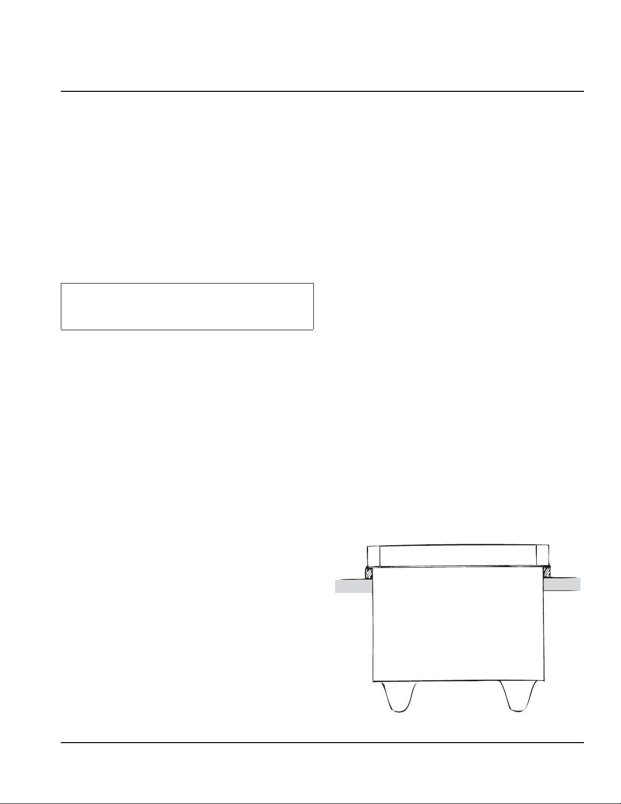
• Place one block of wood on the left side of the
opening at the edge of the cut out. Place another
block of wood on the right side of the opening at the
edge of the cut out.
• See the following drawing. (Drop-in)
• Flat, level counter top (Drop-in)
• Flat, level floor (Free St anding)
• Is there enough space for the Beverage Ice Chest?
• Do not forget the bezel allowances. (Drop-in only)
• How about under the counter? Is there room for the
Beverage Ice Chest with drain and beverage tubing?
• Can the counter top support the weight of the Beverage
Ice Chest PLUS the weight of the ice in the Beverage Ice
Chest PLUS the weight of the beverage tubing? (Drop-in
only)
• Are there any braces or support structures in the counter
top that could be cut and damaged?
• Avoid direct sunlight or close heating / air conditioning
ducts.
• Is a proper drain available?
Part Number 5028106 012/08 2-1
Page 7

Installation Instructions Section 2
!
Caution
Unit Dimensions
MODEL A B C* D E F G H I
1522 (Drop-In) 24.29”
(618.07mm)
2123 (Drop-In) 25.30”
1522
(Freestanding)
2123
(Freestanding)
(1643.84mm)
N/A N/A N/A N/A N/A 22.00"
N/A N/A N/A N/A N/A 23.00"
17.25”
(438.93mm)
23.30”
(1592.98mm)
14.25"
(362.00mm)
14.25"
(362.00mm)
22.00"
(558.80mm)
23.00"
(584.20mm)
15.00”
(381.00mm)
21.00”
(533.40mm)
N/A N/A N/A N/A
N/A N/A N/A N/A
(558.80mm)
(584.20mm)
15.00”
(381.00mm)
21.00”
(533.40mm)
14.25"
(362.00mm)
14.25"
(362.00mm)
Location
Avoid placing the dispenser near heat sources such as
radiators, ovens, refrigeration equipment and direct
sunlight.
Cutting the countertop may decrease its strength.
Counter should be braced to support the dispenser
countertop weight plus ice storage capacity and
weight of icemaker , if applicable.
19.43"
(494.50mm)
19.43"
(494.50mm)
2-2
Part Number 5028106 012/08
Page 8

Section 2 Installation Instructions
!
Warning
Important
When using electric appliances, basic precautions
should always be followed, including the following:
a. Read all the instructions before using the
appliance.
b. To reduce the risk of injury, close
supervision is necessary when an
appliance is used near children.
c. Do not contact moving parts.
d. Only use attachments recommended or
sold by the manufacturer.
e. Do not use outdoors.
f. For a cord-connected appliance, the
following shall be included:
• Do not unplug by pulling on cord. To
unplug, grasp the plug, not the cord.
• Unplug from outlet when not in use and
before servicing or cleaning.
• Do not operate any appliance with a
damaged cord or plug, or after the
appliance malfunctions or is dropped or
damaged in any manner. Contact the
nearest authorized service facility for
examination, repair, or electrical or
mechanical adjustment.
g. For a permanently connected appliance —
Turn the power switch to the off position
when the appliance is not in use and before
servicing or cleaning.
h. For an appliance with a replaceable lamp —
Always unplug before replacing the lamp.
Replace the bulb with the same type.
i. For a grounded appliance — Connect to a
properly grounded outlet only. See
Grounding Instructions.
Due to continuous improvements, this information is
for reference only. Please refer to the dispenser
serial number tag to verify electrical data. Serial tag
information overrides information listed on this page.
Part Number 5028106 012/08 2-3
Page 9

Installation Instructions Section 2
Important
!
Caution
Unit Installation
The unit must be sealed to the counter to comply with
NSF requirements.
1. The outside edge of the chest flange must be seale d
to the counter top. Apply a generous amount of
sealant to the underside of the outside edge of the
flange. (Drop-in)
2. Carefully remove the two blocks of wood from under
the flange. The Beverage Ice Chest will then sit flat
on the counter top. (Drop-in)
3. Wipe excess sealant from around the outer portion
of the flange. (Drop-in)
4. Check to be sure the entire flange edge is sealed to
the counter top. (Drop-in)
5. Apply water, CO2, and syrup pressure to the
beverage system. Check for leaks to the system.
Repair any leaks found.
6. Pour about one gallon cold water into the chest.
Check for any drain line leaks. Repair any leaks
found.
7. o Fill the chest with ice. Allow the coldplate to chill
the beverage tubing inside the coldplate.
NOTE: When installing a Servend DI-1522IC in a stand it
may be necessary to turn the pump head on the pump
deck to allow room for water line connections. See the
illustrations below turning the pump head.
1. Loosen the clamp by turning the 5/16" screw.
2. Turn the pump to the position shown and secure in
place by retightening the clamp screw.
8. Clean your work area while waiting for the cold plate
to cool.
9. After the coldplate has completely chilled, operate
one flavor for about 15 seconds. Take a temperature
reading of the beverage on the next 15 se cond draw .
If the sample drawn is 40° F or lower, go to the next
step. If the beverage is higher than 40° F, wait 10
minutes longer for the beverage to attain the proper
temperatures.Then repeat this step.
10. When the beverage achieves the proper
temperature, set the flow of the water first, then set
the flow of the syrup to achieve the ratio (brix)
recommended by the syrup supplier.
11. Wipe down the Beverage Ice Chest and make final
inspection of the area.
Cutting the countertop may decrease its strength.
Counter should be braced to support the dispenser
countertop weight plus ice storage capacity and
weight of icemaker , if applicable.
2-4
Part Number 5028106 012/08
Page 10

Section 2 Installation Instructions
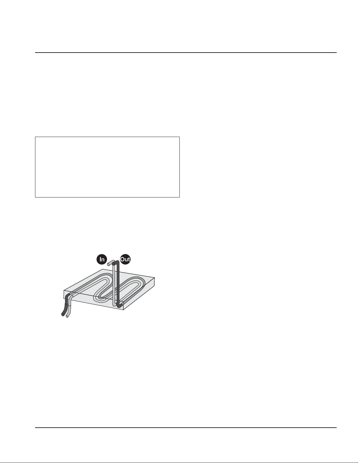
PLUMBING DIAGRAMS
Install the beverage tubing to the approp ria te fittin gs. Re fer to the cold plate drawing on the front of the chest for your
individual set up. See the example below of how your Beverage Ice Chest may be hooked up.
CLEAN UP
Clean up all work areas. Dispose of all packing material,
excess tubing and trash properly .
Part Number 5028106 012/08 2-5
Page 11

Installation Instructions Section 2
THIS PA GE INTENTIO NALLY LEFT BLANK
2-6
Part Number 5028106 012/08
Page 12
About the Bins
Important
Section 3
Operation
• Model 1522 Ice Storage Capacity: 60 lbs. (27.27 kgs)
• Model 2123 Ice Storage Capacity: 80 lbs. (36.36 kgs)
• Freestanding and drop-in versions offered with and
without cold plates.
• Integrated molded plastic base for line protection,
ease of installation and handling.
• Two-piece stainless steel sliding lid.
TO THE USER OF THIS SERVICE MANUAL, THIS
MANUAL IS A GUIDE FOR INSTALLING THIS
EQUIPMENT. REFER TO THE TABLE OF
CONTENTS FOR PAGE LOCATION FOR DETAILED
INFORMATION PERTAINING TO QUESTIONS THAT
ARISE DURING INSTALLATION AND START-UP OF
THIS EQUIPMENT.
STANDS
Stands are designed to accommodate drop-in ice bins
and to provide an enclosure for carbonators. See
instructions provided with those items for proper
installation and connections.
COLD PLATE BEVERAGE COOLING
UNIT INSPECTION
This section covers unpacking, inspecting, selecting location,
installing the unit, and preparing for operation. Thoroughly
inspect the unit upon delivery . Immediately report any damage
that occurred during transportation to the delivery carrier .
Request a written inspection report from a claims inspector to
document any necessary claim.
1. After the unit has been unpacked, remove the keys. The
key will be needed to perform brixing of valves. Hold onto
the keys until such time to forward them to the respective
owner/operator. Remove t ape (which secures grid in
place in drain pan) from grid and other packing material.
2. Make sure all items are present and in good condition.
Loose shipped items in the carton include the drain kit
parts and the instructions.
3. Inspect unit for any external damages.
If you have an internal carbonated unit the unit is pre-plumbed
at the factory . The inlets for CO
the splash panel. There are two inlets for water and one inlet
for CO
2. If you have questions refer to the plumbing diagram
on your equipment.
2 and water are located behind
A cold plate is a block of aluminum with serpentine
stainless steel tubes molded inside the aluminum block.
The cold plate is approximately the same length and
width as the bottom of the dispenser bin. Ice sits on top
of the cold plate and cools the cold plate. The stainless
steel tubes inside the cold plate carry carbonated water
(soda water), noncarbonated water (plain water) and
syrup to the beverage valves. While flowing through the
stainless steel tubes in the cold plate, water and syrup
are chilled to serving temperature.
Part Number 5028106 012/08 3-1
Page 13

Operation Section 3
THIS PA GE INTENTIO NALLY LEFT BLANK
3-2
Part Number 5028106 012/08
Page 14

Section 4
!
Caution
!
Warning
!
Warning
!
Warning
!
Warning
Maintenance
Cleaning
All cleaning MUST meet your local health codes. These
instructions are included as a guide to cleaning.
DAILY CLEANING
The daily cleaning of the Beverage Ice Chest can be
accomplished within just a few minutes. Using mild soap
and warm water, wipe down all visible exterior surfaces
of the Beverage Ice Chest, being careful not to get any
of the soapy solution in the ice chest of the Beverage Ice
Chest.
Use only warm soapy water to clean the exterior of
the tower. Do not use solvents or other cleaning
agents. Do not pour hot coffee into the drain pan.
Pouring hot coffee down the drain pan can
eventually crack the drain pan, especially if the
drain pan is cold or still contains ice. DO NOT clean
this unit using high presure water jets or sprayers
Electric Shock Hazard
Unplug unit before servicing or cleaning.
sodium hypochlorite) with 2 gallons of 120°F water.
The mixture should not exceed 100 PPM of chlorine.
9. Sanitize the ice bin and cold plate with the sanitizing
solution for at least 10 seconds.
NOTE: Allow to air dry. Do not rinse.Do NOT rinse any
part with tap water after sanitizing as this may leave
traces of unwanted bacteria on the equipment.
Beverage System
You should also clean the beverage system monthly.
Please check with your syrup supplier for specific
instructions. The instructions below are provided as a
general guide for beverage cleaning. This procedure is
for cleaning and sanitization of one syrup circuit at a
time. Repeat this procedure for each syrup line in your
system.
Cleaning Checklist
•Check CO
the primary regulator gauge will point to a shaded
area that reads “Low CO
Cylinder.”
• Check syrup supply.
• Clean drain pan, grid, and splash panel.
• Clean the valve nozzles and diffusers.
supply . If CO2 supply is low, an arrow on
2
” or “Change CO2
2
When using cleaning fluids or chemicals, rubber
gloves and eye protection should be worn .
MONTHLY CLEANING
Clean and sanitize the ice bin and cold plate:
1. Remove all ice from the ice bin.
2. Remove the ice bin strainer by lifting it straight up.
3. Prepare a mild detergent solution using warm
(100°F) water.
4. Wash the ice bin using a sponge and the mild
detergent solution.
5. Wash the cold plate using a soft, nylon bristle brush
and the mild detergent solution.
6. Pour the remaining detergent solution in the drain
pan and watch for obstruction of flow.
7. Rinse the ice bin and cold plate with clean water.
8. Prepare 2 gallons of sanitizing solution by mixing 1
ounce of household bleach (that contains 5.25%
Sanitizing
BEVERAGE SYSTEM CLEANING
Flush sanitizing solution from syrup system.
Residual sanitizing solution left in system could
create a health hazard.
When using cleaning fluids or chemicals, rubber
gloves and eye protection must be wor n.
Sanitize the beverage system at initial start-up as well as
regularly scheduled cleaning. The drain pan must be in
place under soda valves, to carry away detergent and
sanitizing agents that will be flushed through valves.
Part Number 5028106 012/08 4-1
Page 15

Maintenance Section 4
Bag
side
connector
BAG-IN-BOX SYSTEM SANITATION
The procedure below is for the sanitation of one
syrup circuit at a time. Repeat to sanitize additional
circuits.
You will need the following items to clean and sanitize
the Bag-in-Box (BIB) beverage system:
• Three (3) clean buckets
• Plastic brush or soft cloth
• Mild detergent
• Unscented bleach (5% Na CL O) or
Commercial sanitizer
• Bag-In-Box bag connector
1. Prepare the following in the buckets:
• Bucket 1 — warm to hot tap water for rinsing.
• Bucket 2 — mild detergent and warm to hot
water.
• Bucket 3 — mix a solution of unscented bleach
(5% Na CL O) or commercial sanitizer and warm
to hot water. Mi xture should supply 100 PPM
available chlorine (1/4 oz. bleach to 1 gallon
water).
2. Disconnect the “syrup-line side” of the bag-in-box
connector.
6. Connect Bucket 2 to system.
7. Draw detergent solution through system until
solution is dispensed.
8. Repeat steps 2-7 until all syrup circuits contain
detergent solution.
9. Allow detergent solution to remain in the system for
5 minutes.
10. Connect Bucket 3 to system.
11. Draw sanitizing solution through system until
solution is dispensed.
12. Repeat step 11 until all syrup circuits contain
sanitizer solution.
13. Allow sanitizer solution to remain in system for 15
minutes.
14. Remove nozzles and diffusers from beverage
valves.
15. Scrub nozzles, diffusers and all removable valve
parts (except electrical parts) with a plastic brush or
a soft cloth and the detergent solution.
16. Soak nozzles, diffusers and removable valve parts
(except electrical parts) in sanitizer for 15 minutes.
17. Replace nozzles, diffusers and valve parts.
18. Connect Bucket 1 to system.
19. Draw rinse water through system until no presence
of sanitizer is detected.
3. Rinse connector with warm tap water.
4. Connect syrup connector to BIB connector and
immerse both into Bucket 1. A “bag-side” connector
can be created by cutting the connector from an
empty disposable syrup bag.
5. Draw rinse water through system until clean water is
dispensed. Most beverage valves allow the syrup
side to be manually activated by depressing the
syrup pallet.
4-2
20. Attach syrup connectors to BIBs.
21. Draw syrup through system until only syrup is
dispensed.
22. Discard first 2 drinks.
FIGAL BEVERAGE SYSTEM
1. Prepare the following in three clean Figal tanks:
• Rinse t ank - fill with room temperature tap water.
• Detergent tank - mix a pproved beverage system
cleaner with warm water as directed.
• Sanitizing tank - mix a solution of unscented
bleach (5% Na CL O) or commercial sanitizer
and warm to hot water. Mixture should supply
100 PPM available chlorine (1/4 oz. bleach to
1 gallon water).
2. Disconnect all product and water lines from product
tanks and remove carbonator.
3. Locate the Figal syrup tank for the circuit to be
sanitized. Remove both quick disconnects from the
Part Number 5028106 012/08
Page 16

Section 4 Maintenance
!
Caution
Figal syrup tank. Rinse quick disconnects in tap
water.
4. Connect rinse tank to the syrup line. Draw clean
rinse water through the valve until syrup is flushed
from the system.
5. Connect detergent tank to the syrup line and draw
detergent through the valve for two minutes. Then,
allow remaining detergent to stay in the system for
five minutes.
6. Connect rinse tank to the syrup line. Draw clean
rinse water through the valve until detergent is
flushed from the system.
7. Remove valve nozzle and diffuser as shown in Daily
Cleaning instructions. Using a plastic brush or a soft
cloth and warm water, scrub the nozzle, diffuser,
bottom of the dispensing valve and cup lever, if
applicable.
8. Place removable valve parts (EXCEPT solenoids) in
sanitizing solution for 15 minutes.
9. Replace valve diffuser and nozzle on the beverage
valve.
10. Connect sanitizer tank to the syrup line and draw
sanitizer through the valve for two minutes. Allow
sanitizer to remain in the system for a minimum of
15 minutes.
19. Draw syrup through th e lines to rin se the sys te m.
Discard drinks until at least two cups of satisfactory
tasting beverage are dispensed through the valve.
Shipping, Storage and Relocation
Before shipping, storing, or relocating this unit,
syrup systems must be sanitized. After sanitizing, all
liquids (sanitizing solution and water) must be
purged from the unit. A freezing environment
causes residual sanitizing solution or water
remaining inside the unit to freeze, resulting in
damage to internal components.
11. Reconnect syrup and carbonated water lines.
12. Draw syrup through the lines to rinse the system.
Discard drinks until at least two cups of satisfactory
tasting beverage are dispensed through the valve.
13. Connect rinse tank to the syrup line. Draw clean
rinse water through the valve until detergent is
flushed from the system.
14. Remove valve nozzle and diffuser as shown in Daily
Cleaning instructions on Pages 25 and 26. Using a
plastic brush or a soft cloth and warm water, scrub
the nozzle, diffuser, bottom of the dispensing valve
and cup lever, if applicable.
15. Place removable valve parts (EXCEPT solenoids) in
sanitizing solution for 15 minutes.
16. Replace valve diffuser and nozzle on the beverage
valve.
17. Connect sanitizer tank to the syrup line and draw
sanitizer through the valve for two minutes. Allow
sanitizer to remain in the system for a minimum of
15 minutes.
18. Reconnect syrup and carbonated water lines.
Part Number 5028106 012/08 4-3
Page 17

Maintenance Section 4
4-4
Part Number 5028106 012/08
Page 18

Section 5
Before Calling for Service
Checklist
If a problem arises during operation of your dispenser, follow the checklist below before calling service. Routine
adjustments and maintenance procedures are not covered by the warranty.
DRINK TROUBLESHOOTING
Problem Possible Cause Corrective Action
Drinks are too sweet
(heavy).
Drinks are not sweet
enough (light).
Drinks are foaming.
Drinks are warm.
1. Beverage dispenser out of
adjustment (brix).
2. No ice on coldplate.
3. Syrup is too warm.
1. Beverage dispenser is out of
adjustment (brix).
2. Syrup is too cold.
1. No ice on coldplate.
2. Syrup is too warm.
3. Carbonator CO2 pressure set
too high.
1. No ice on coldplate.
2. Water temperature too high.
1. Brix beverage dispenser.
2. Fill ice bin.
3. Store syrup between 40° F and 90° F.
1. Brix beverage dispenser.
2. Store syrup between 40° F and 90 o F.
1. Fill ice bin.
2. Store syrup between 40° F and 90° F.
3. Set carbonator CO2 to 75 psig.
4. Set water pressure between 40 and 50 psi.
1. Fill ice bin
2. Incoming water temperature should be between
40° F F and 90° F.
Part Number 5028106 012/08 5-1
Page 19

Before Calling for Service Section 5
THIS PA GE INTENTIO NALLY LEFT BLANK
5-2
Part Number 5028106 012/08
Page 20

© 2008 Manitowoc
Continuing product improvements
may necessitate change of
specifications without notice.
Part Number 5028106 012/08
Manitowoc Beverage Equipment
Sellersburg, IN 47172, USA
Ph: 812-246-7000 Fax: 812-246-7024
Visit us online at: www.manitowocfsg.com
2100 Future Drive
 Loading...