

Page 1
CEV SERIES
Beverage Dispensers
Installation, Use & Care Manual
This manual is updated as new information and models are released.
Visit our website for the latest manual. www.manitowocfsg.com
Leader in Ice & Beverage Dispensers
Part Number 020004000 10/13
Page 2
Safety Notices
! Warning
!
Caution
Important
!
Caution
Important
! Warning
As you work on Manitowoc equipment, be sure to pay
close attention to the safety notices in this manual.
Disregarding the notices may lead to serious injury and/
or damage to the equipment.
Throughout this manual, you will see the following types
of safety notices:
Text in a Warning box alerts you to a potential
personal injury situation. Be sure to read the
Warning statement before proceeding, and work
carefully.
Text in a Caution box alerts you to a situation in
which you could damage the equipment. Be sure to
read the Caution statement before proc eeding, and
work carefully.
Procedural Notices
As you work on Manitowoc equipment, be sure to read
the procedural notices in this manual. These notices
supply helpful information which may assist you as you
work.
Throughout this manual, you will see the following types
of procedural notices:
Read These Before Proceeding:
Proper installation, care and maintenance are
essential for maximum performance and troublefree operation of your Manitow oc equipment. Read
and understand this manual. It contains valuable
care and maintenance information. If you encounter
problems not covered by this manual, do not
proceed, contact Manitowoc Foodservice Group.
We will be happy to provide assistance.
Routine adjustments and maintenance procedures
outlined in this manual are not covered by the
warranty.
PERSONAL INJURY POTENTIAL
Do not operate equipment that has been misused,
abused, neglected, damaged, or altered/modified
from that of original manufactured specifications.
NOTE: SAVE THESE INSTRUCTIONS.
Text in an Important box provides you with
information that may help you perform a procedure
more efficiently. Disregarding this information will
not cause damage or injury, but it may slow you
down as you work.
NOTE: Text set off as a Note provides you with simple,
but useful, extra information about th e pr oce dur e yo u
are performing.
We reserve the right to make product improvements at any time.
Specifications and design are subject to change without notice.
Page 3

Section 1
General Information
Read This Manual. . . . . . . . . . . . . . . . . . . . . . . . . . . . . . . . . . . . . . . . . . . . . . . . . 1-1
Unit Inspection . . . . . . . . . . . . . . . . . . . . . . . . . . . . . . . . . . . . . . . . . . . . . . . . . . . 1-1
Model Numbers. . . . . . . . . . . . . . . . . . . . . . . . . . . . . . . . . . . . . . . . . . . . . . . . . . . 1-1
Serial Number Location . . . . . . . . . . . . . . . . . . . . . . . . . . . . . . . . . . . . . . . . . . . . 1-2
Warranty Information . . . . . . . . . . . . . . . . . . . . . . . . . . . . . . . . . . . . . . . . . . . . . . 1-2
Section 2MBS
Installation Instructions
General System Overview . . . . . . . . . . . . . . . . . . . . . . . . . . . . . . . . . . . . . . . . . . 2-1
Pre-installation Checklist. . . . . . . . . . . . . . . . . . . . . . . . . . . . . . . . . . . . . . . . . . . 2-2
Selecting Locations . . . . . . . . . . . . . . . . . . . . . . . . . . . . . . . . . . . . . . . . . . . . . . . 2-4
Footprints . . . . . . . . . . . . . . . . . . . . . . . . . . . . . . . . . . . . . . . . . . . . . . . . . . . . . . . 2-6
Location. . . . . . . . . . . . . . . . . . . . . . . . . . . . . . . . . . . . . . . . . . . . . . . . . . . . . . . . . 2-8
Electrical . . . . . . . . . . . . . . . . . . . . . . . . . . . . . . . . . . . . . . . . . . . . . . . . . . . . . . . . 2-9
Grounding Instructions . . . . . . . . . . . . . . . . . . . . . . . . . . . . . . . . . . . . . . . . . . . . 2-9
Unit Installation. . . . . . . . . . . . . . . . . . . . . . . . . . . . . . . . . . . . . . . . . . . . . . . . . . . 2-11
Table of Contents (continued)
Placing Unit in the Operating Position . . . . . . . . . . . . . . . . . . . . . . . . . . . . 2-4
CEV30 Footprint . . . . . . . . . . . . . . . . . . . . . . . . . . . . . . . . . . . . . . . . . . . . . 2-6
CEV40 Footprint . . . . . . . . . . . . . . . . . . . . . . . . . . . . . . . . . . . . . . . . . . . . . 2-7
General . . . . . . . . . . . . . . . . . . . . . . . . . . . . . . . . . . . . . . . . . . . . . . . . . . . . 2-9
Minimum Circuit Ampacity . . . . . . . . . . . . . . . . . . . . . . . . . . . . . . . . . . . . . 2-9
Electrical Requirements . . . . . . . . . . . . . . . . . . . . . . . . . . . . . . . . . . . . . . . 2-9
Voltage . . . . . . . . . . . . . . . . . . . . . . . . . . . . . . . . . . . . . . . . . . . . . . . . . . . . 2-9
Minimum Circuit Amperage Chart . . . . . . . . . . . . . . . . . . . . . . . . . . . . . . . . 2-9
Refrigerant . . . . . . . . . . . . . . . . . . . . . . . . . . . . . . . . . . . . . . . . . . . . . . . . . 2-9
Counter Sealing . . . . . . . . . . . . . . . . . . . . . . . . . . . . . . . . . . . . . . . . . . . . . 2-11
Filling the water tank . . . . . . . . . . . . . . . . . . . . . . . . . . . . . . . . . . . . . . . . . . 2-11
Refrigeration System Start . . . . . . . . . . . . . . . . . . . . . . . . . . . . . . . . . . . . . 2-12
Incoming Water Supply requirements . . . . . . . . . . . . . . . . . . . . . . . . . . . . . 2-12
Connecting the Drain Pan Hose . . . . . . . . . . . . . . . . . . . . . . . . . . . . . . . . . 2-12
Carbonator Tank Purge Tube Routing . . . . . . . . . . . . . . . . . . . . . . . . . . . . 2-13
Connecting Water & Syrup Supply Line(s) . . . . . . . . . . . . . . . . . . . . . . . . . 2-14
Premix Pressures . . . . . . . . . . . . . . . . . . . . . . . . . . . . . . . . . . . . . . . . . . . . 2-14
Plumbing Diagrams . . . . . . . . . . . . . . . . . . . . . . . . . . . . . . . . . . . . . . . . . . . 2-15
Carbonated/non-carbonated Conversion Instructions . . . . . . . . . . . . . . . . 2-17
CEV Bag-in-Box (BIB) Start-up . . . . . . . . . . . . . . . . . . . . . . . . . . . . . . . . . . 2-17
Install Labels . . . . . . . . . . . . . . . . . . . . . . . . . . . . . . . . . . . . . . . . . . . . . . . . 2-17
ADA Key Pads . . . . . . . . . . . . . . . . . . . . . . . . . . . . . . . . . . . . . . . . . . . . . . 2-18
Part Number 020004000 10/13
i
Page 4

Section 3
Operation
Table of Contents (continued)
Component Identification . . . . . . . . . . . . . . . . . . . . . . . . . . . . . . . . . . . . . . . . . . . 3-1
Sequence of Operation. . . . . . . . . . . . . . . . . . . . . . . . . . . . . . . . . . . . . . . . . . . . . 3-1
Unit Inspection . . . . . . . . . . . . . . . . . . . . . . . . . . . . . . . . . . . . . . . . . . . . . . . 3-1
Beverage Valves . . . . . . . . . . . . . . . . . . . . . . . . . . . . . . . . . . . . . . . . . . . . . 3-2
Carbonated Water . . . . . . . . . . . . . . . . . . . . . . . . . . . . . . . . . . . . . . . . . . . . 3-3
Syrup Delivery System . . . . . . . . . . . . . . . . . . . . . . . . . . . . . . . . . . . . . . . . 3-3
Back Room Package . . . . . . . . . . . . . . . . . . . . . . . . . . . . . . . . . . . . . . . . . . 3-3
Figal System . . . . . . . . . . . . . . . . . . . . . . . . . . . . . . . . . . . . . . . . . . . . . . . . 3-4
Figal Tanks . . . . . . . . . . . . . . . . . . . . . . . . . . . . . . . . . . . . . . . . . . . . . . . . . 3-4
Racking . . . . . . . . . . . . . . . . . . . . . . . . . . . . . . . . . . . . . . . . . . . . . . . . . . . . 3-4
B-I-B . . . . . . . . . . . . . . . . . . . . . . . . . . . . . . . . . . . . . . . . . . . . . . . . . . . . . . 3-4
Pumps . . . . . . . . . . . . . . . . . . . . . . . . . . . . . . . . . . . . . . . . . . . . . . . . . . . . . 3-4
Auto Bag Selectors . . . . . . . . . . . . . . . . . . . . . . . . . . . . . . . . . . . . . . . . . . . 3-4
Operation Checks and Adjustments . . . . . . . . . . . . . . . . . . . . . . . . . . . . . . . . . . 3-5
Electronic Ice and & Carbonation Control . . . . . . . . . . . . . . . . . . . . . . . . . . 3-5
Section 4
Maintenance
Cleaning. . . . . . . . . . . . . . . . . . . . . . . . . . . . . . . . . . . . . . . . . . . . . . . . . . . . . . . . . 4-1
Sanitizing . . . . . . . . . . . . . . . . . . . . . . . . . . . . . . . . . . . . . . . . . . . . . . . . . . . . . . . . 4-2
Shipping, Storage and Relocation. . . . . . . . . . . . . . . . . . . . . . . . . . . . . . . . . . . . 4-4
Section 5
Before Calling for Service
Checklist . . . . . . . . . . . . . . . . . . . . . . . . . . . . . . . . . . . . . . . . . . . . . . . . . . . . . . . . 5-1
Pump Troubleshooting. . . . . . . . . . . . . . . . . . . . . . . . . . . . . . . . . . . . . . . . . . . . . 5-2
Daily Cleaning . . . . . . . . . . . . . . . . . . . . . . . . . . . . . . . . . . . . . . . . . . . . . . . 4-1
Water Bath . . . . . . . . . . . . . . . . . . . . . . . . . . . . . . . . . . . . . . . . . . . . . . . . . . 4-1
Cleaning Checklist . . . . . . . . . . . . . . . . . . . . . . . . . . . . . . . . . . . . . . . . . . . . 4-2
Preventive Maintenance . . . . . . . . . . . . . . . . . . . . . . . . . . . . . . . . . . . . . . . 4-2
Beverage System Cleaning . . . . . . . . . . . . . . . . . . . . . . . . . . . . . . . . . . . . . 4-2
Drink Troubleshooting . . . . . . . . . . . . . . . . . . . . . . . . . . . . . . . . . . . . . . . . . 5-1
ii Part Number 020004000 10/13
Page 5
Section 1
!
Warning
General Information
Read This Manual
Manitowoc Beverage Systems (MBS) developed this
manual as a reference guide for the owner/oper ator a nd
installer of this equipment. Please read this manual
before installation or operation of the machine. A
qualified service technician must perform inst allation and
start-up of this equipment, consult Section 5 within this
manual for service assistance.
If you cannot correct the service problem, call your MBS
Service Agent or Distributor. Always have your model
and serial number available when you call.
Your Service Agent ____________________________
Service Agent Telephone Number_________________
Your Local MBE Distributor ______________________
Distributor Telephone Number____________________
Model Number _______________________________
Serial Number ________________________________
Installation Date ______________________________
Unit Inspection
Model Numbers
This manual covers the following models:
Beverage Dispensers
CEVe-30, CEVe-40, CEVi-30, CEVi-40, CEVj-30
Thoroughly inspect the unit upon delivery. Immediately
report any damage that occurred during tr ansportation to
the delivery carrier. Request a written inspection report
from a claims inspector to document any necessary
claim.
PERSONAL INJURY POTENTIAL
Do not operate equipment that has been misused,
abused, neglected, damaged, or altered/modified
from that of original manufactured specifications.
Part Number 020004000 10/13 1-1
Page 6
General Information Section 1
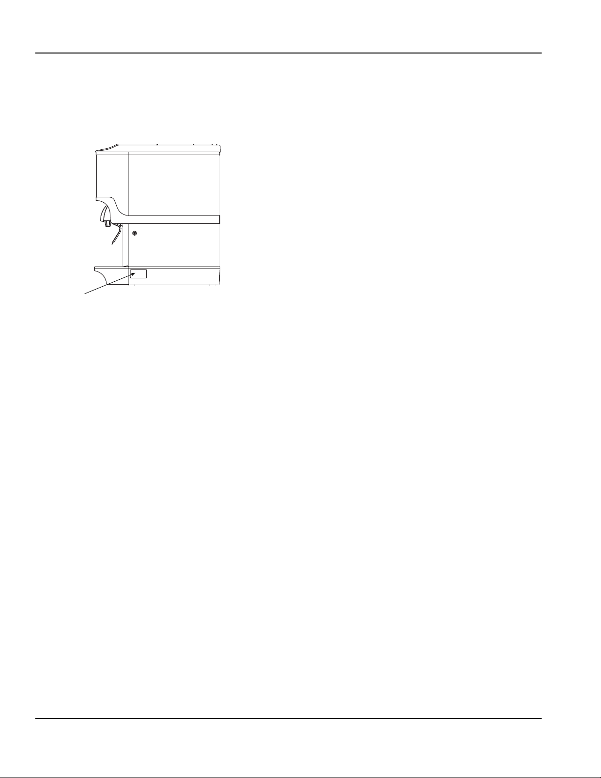
Label
Serial Number Location
This number is required when requesting information
from your local distributor. The serial number is listed on
the SERIAL NUMBER DECAL affixed to the dispenser.
Serial Number Location
Warranty Information
Consult your local MBS Distributor for terms and
conditions of your warranty. Your warranty specifically
excludes all beverage valve brixing, general
adjustments, cleaning, accessories and related
servicing.
Your warranty card must be returned to MBS to activate
the warranty on this equipment. If a warranty card is not
returned, the warranty period can begin when the
equipment leaves the MBS factory.
No equipment may be returned to MBS without a written
Return Materials Authorization (RMA). Equipment
returned without an RMA will be refused at MBS’s dock
and returned to the sender at the sender’s expense.
Please contact your local MBS distributor for return
procedures.
1-2
Part Number 020004000 10/13
Page 7
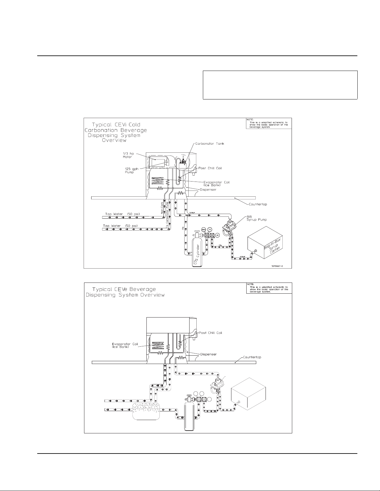
General System Overview
Important
90-
1800
60
100
CO
2
CO
2
CARBONATED WATER
NON-CARBONATED WATER
SYRUP
SYRUP
Carbonator
Tank
CO
2
Cylinder
Tap Water
Tap Water
Bag-In-Box
Syrup
Carton
BIB
Syrup Pump
Section 2
Installation Instructions
These instructions are provided to assist the qualified
installer. Contact your Manitowoc Beverage Equipment
Service Agent or call Manitowoc Beverage Equipment
for information regarding start-up service s.
Failure to follow these installation guidelines may
affect warranty coverage.
TO THE CARB TANK
Typical CEV Series Internal Carbonation Beverage Dispensing System
Typical CEV External Carbonation (Ambient) Beverage Dispensing System
Part Number 020004000 10/13 2-1
Page 8
Installation Instructions Section 2
Pre-installation Checklist
When installing any system, first make sure the major components are available. Generally the major components
necessary for an installation are:
Pre-mix System:
CO
regulator set
2
Post Mix System:
CO2 regulator set
Product connectors for Figal tank
Gas connectors for Figal tank
Beverage dispenser
Beverage tubing
tank
CO
2
Figal beverage tanks
Stepless (Oetiker) clamps
Chain for CO
tank
2
Beverage dispenser
Beverage tubing
tank
CO
2
Carbonator
Stepless (Oetiker) clamps
Chain for CO
Figal system also:
Syrup connectors for Figal tank
tank
2
B-I-B System also:
B-I-B connectors
B-I-B regulator set
B-I-B rack
B-I-B syrup boxes
2-2
Gas connectors for Figal tank
Figal syrup tanks
Part Number 020004000 10/13
Page 9
Section 2 Installation Instructions
Bulk Syrup System also:
Syrup connectors for Bulk tank
Gas connectors for Bulk tank
Bulk syrup tanks
Double Check:
Do you have enough space to install the
dispenser or a dispenser and top mounted
cuber?
Does top mounted cuber (if utilized) have a
minimum of 6 inches (15.3 cm) clearance on all
sides?
Also consider the location of the following items before installation:
Water line
Drain
Power outlet
Heating and air conditioning ducts
Is the countertop level?
Can the countertop support the weight of the
dispenser, or the dispenser/cuber combination
plus the weight of the stored ice?
Part Number 020004000 10/13 2-3
Page 10
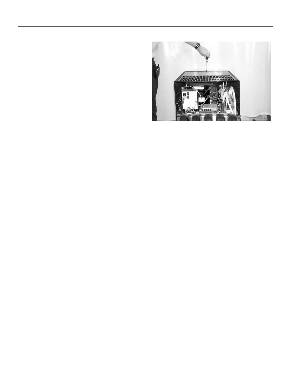
Installation Instructions Section 2
ABOVE: How to Remove the Bonnet
Selecting Locations
The CEV may be island-mounted or installed on a fr ont
or rear counter. Locate the CEV so the following
requirements are satisfied: CEV is for indoor use only
and must NOT be placed in an area where a water jet or
similar high pressure sprayer could be used.
1. CEV must be installed near a properly grounded
electrical outlet with proper electrical requirements
fused at proper amperage or circuit connected
through an equivalent HACR circuit breaker with
ELCB (GFCI). REFER TO UNIT NAMEPLATE FOR
THE REQUIRED POWER CIRCUIT OPERATING
VOLTAGE. HERTZ AND THE MINIMUM CIRCUIT
AMPACITY OF THE CEV. No other electrical
equipment should be connected to this circuit. ALL
ELECTRICAL WIRING MUST CONFORM TO
NATIONAL AND LOCAL ELECTRICAL CODES.
MAIN PLUG MUST BE ACCESSIBLE FOR
DISCONNECTION.
2. A minimum of 15-inches clearance must be
maintained above the CEV to the nearest
obstruction (shelf, cupboard, ceiling, etc.) and 4inches clearance between the back of the CEV and
the wall and 12-inches between each side and the
wall. CEV has a top air outlet and is to remain free of
all objects. Do not place anything on top of the CEV.
The rear grill of the CEV must be unobstructed to
allow air to enter the hood. This will also allow
access to the condenser filter for cleaning.
3. If a permanent drain is to be used place CEV close
to a permanent drain in order to route the drain pan
hose to the permanent drain. Water tank overflow
hose goes into the drain pan.
PLACING UNIT IN THE OPERATING POSITION
The CEV must be level horizontally from right to left and
front to rear. CEV inlet supply lines, power cord, and
drain pan hose must either be routed out of the CEV
base rear access hole, or through a hole cut in the
countertop under the CEV Unit. Proceed to applicable
installation procedure. Two plastic tubing brackets are
mounted under the CEV to hold the lines in place. The
rear access cover may be removed, turned and installed
to provide a brace to prevent the CEV from being
pushed flat against the wall.Dimensions
Island Mount
Place the CEV in location on the countertop flush with
the countertop edge. Mark CEV’s center line on the edge
of the countertop, then move the CEV to one side.
Starting at the center line mark on the edge of the
countertop, measure back 12-inches for the location of a
hole at least 4-inches to be cut into the countertop. Cut
at least a 4 inch hole in the countertop where indicated.
Place the CEV in position over the hole. Route the inlet
supply lines, power cord, carbonator tank purge tube
and drain pan hose down through the hole in the
countertop.Install the line outlet plug, provided with the
CEV in the base back access hole. The area around the
inlet supply lines at the flanged hole behind the front
access panel must be closed and sealed.
Counter Mount
Place the CEV in location on the countertop. Route CEV
inlet supply lines, power cord, carbonator tank purge
tube and drain pan hose out of the base back access
hole. Area around inlet supply lines at flanged hole
behind front access panel must be closed and sealed.
2-4
Part Number 020004000 10/13
Page 11
Section 2 Installation Instructions
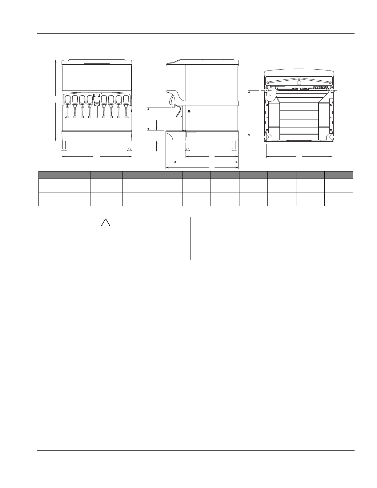
B
C
D
G
F
E
I
H
A
!
Caution
Counter Electric Dispenser Dimensions
* C = Valve height using Flomatic Valves.
MODEL A B C* D E F G H I
CEV-30 29.88"
(75.9 cm)
CEV-40 29.88"
(75.9 cm)
20.50"
(52.7 cm)
26.00"
(66.0 cm)
11.76"
(29.8 cm)
11.76"
(29.8 cm)
4.44"
(11.3 cm)
4.44"
(11.3 cm)
N/A N/A 25.75"
(65.4 cm)
N/A N/A 25.75"
(65.4 cm)
17.00"
(43.1 cm)
17.00"
(43.1 cm)
17.50"
(44.4 cm)
23.00"
(58.4 cm)
Cutting the countertop may decrease its strength.
Counter should be braced to support the dispenser
countertop weight plus ice storage capacity and
weight of icemaker , if applicable.
Part Number 020004000 10/13 2-5
Page 12
Installation Instructions Section 2
!
Caution
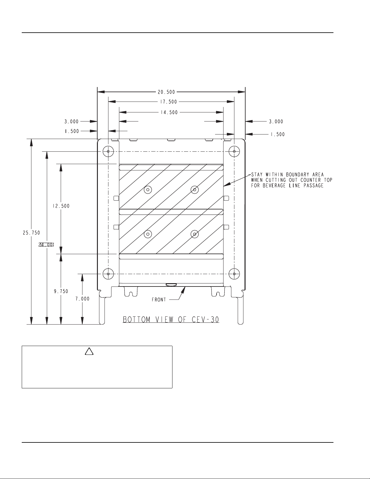
Footprints
CEV30 FOOTPRINT
Cutting the countertop may decrease its strength.
Counter should be braced to support the dispenser
countertop weight plus ice storage capacity and
weight of icemaker , if applicable.
2-6
Part Number 020004000 10/13
Page 13

Section 2 Installation Instructions
!
Caution
CEV40 FOOTPRINT
Cutting the countertop may decrease its strength.
Counter should be braced to support the dispenser
countertop weight plus ice storage capacity and
weight of icemaker , if applicable.
Part Number 020004000 10/13 2-7
Page 14

Installation Instructions Section 2
!
Warning
Location
Avoid placing the dispenser near heat sources such as
radiators, ovens, refrigeration equipment and direct
sunlight.
Carbon Dioxide (CO2) displaces oxygen. Exposure
to a high concentration of CO
which are followed rapidly by loss of consciousness
and suffocation. If a CO
particularly in a small area, immediately ventilate
the area before repairing the leak. CO
pumps should not be installed in an enclosed
space. An enclosed space can be a cooler or small
room or closet. This may include convenience
stores with glass door self serve coolers. If you
suspect CO
may build up in an area, venting of the
2
B-I-B pumps and / or CO
utilized.
gas causes tremors,
2
gas leak is suspected,
2
lines and
2
monitors should be
2
2-8
Part Number 020004000 10/13
Page 15

Section 2 Installation Instructions
!
Warning
Important
!
Warning
!
Warning
Electrical
GENERAL
All wiring must conform to local, state and national codes.
MINIMUM CIRCUIT AMPACITY
The minimum circuit ampacity is used to help select the
wire size of the electrical supply. (Minimum circuit
ampacity is not the beverage/ice machine’s running amp
load.) The wire size (or gauge) is also dependent upon
location, materials used, length of run, etc., so it must be
determined by a qualified electrician.
ELECTRICAL REQUIREMENTS
Refer to Machine Model/Serial Plate for voltage/
amperage specifications.
VOLTAGE
The standard voltage for CEV Series dispensers is
120VAC-60Hz 1 Ph. A power cord is provided with
120V AC-60Hz models only. 220/240 Volt s - 50 Hz - 1 Ph,
208/230 Volts - 60 Hz - 1 Ph are also available.
MINIMUM CIRCUIT AMPERAGE CHART
Dispenser Voltage/Cycle Fuse Size
CEV-30,
CEV-40
120/60 20 amp
220/50, 240/50,
208/60, 230/60
10 amp 4.5 Operating
Circuit
Amps
8.2 Operating
amps
13 FLA
amps
7.0 FLA
REFRIGERANT
Dispenser Voltage/Cycle Refrigerant Compressor
CEV-30,
CEV-40
120/60, 220/50,
240/50, 208/60,
230/60
R-134a - 8 oz
1/3 HP
Due to continuous improvements, this information is
for reference only. Please refer to the dispenser
serial number tag to verify electrical data. Serial tag
information overrides information listed on this page.
Grounding Instructions
Risk of electrical shock. Connect to a properly
grounded outlet only.
This appliance must be grounded. In the event of
malfunction or breakdown, grounding provides a path of
least resistance for electric current to reduce the risk of
electric shock. This appliance is equipped with a cord
having an equipment-grounding conductor and a
grounding plug. The plug must be plugged into an
appropriate outlet that is properly installed and grounded
in accordance with all local codes and ordinances.
Improper connection of the equipment-grounding
conductor can result in a risk of electric shock. The
conductor with insulation having an outer surface
that is green with or without yellow stripes is the
equipment grounding conductor. If repair or
replacement of the cord or plug is necessary, do not
connect the equipment-grounding conductor to a
live terminal. Check with a qualified electrician or
serviceman if the grounding instructions are not
completely understood, or if in doubt as to whether
the appliance is properly grounded. Do not modify
the plug provided with the appliance — if it will not fit
the outlet, have a proper outlet installed by a
qualified electrician.
Optimum Ambient Conditions are between 50°F and
95°F (10°C and 35°C).
Part Number 020004000 10/13 2-9
Page 16

Installation Instructions Section 2
!
Warning
When using electric appliances, basic precautions
should always be followed, including the following:
a. Read all the instructions before using the
appliance.
b. To reduce the risk of injury, close
supervision is necessary when an
appliance is used near children.
c. Do not contact moving parts.
d. Only use attachments recommended or
sold by the manufacturer.
e. Do not use outdoors.
f. For a cord-connected appliance, the
following shall be included:
• Do not unplug by pulling on cord. To
unplug, grasp the plug, not the cord.
• Unplug from outlet when not in use and
before servicing or cleaning.
• Do not operate any appliance with a
damaged cord or plug, or after the
appliance malfunctions or is dropped or
damaged in any manner. Contact the
nearest authorized service facility for
examination, repair, or electrical or
mechanical adjustment.
g. For a permanently connected appliance —
Turn the power switch to the off position
when the appliance is not in use and before
servicing or cleaning.
h. For an appliance with a replaceable lamp —
Always unplug before replacing the lamp.
Replace the bulb with the same type.
i. For a grounded appliance — Connect to a
properly grounded outlet only. See
Grounding Instructions.
2-10
Part Number 020004000 10/13
Page 17

Section 2 Installation Instructions
!
Warning
Unit Installation
COUNTER SEALING
In order for all CEV units to comply with NSF requirements
within the United Stat es, the CEV base must be sealed to
the countertop unless the optional 4” legs are installed. All
access holes to the base must be sealed. If the 4” legs are
installed, proceed to Filling the Water Tank, otherwise
proceed as follows to seal the CEV base:
A. Tilt CEV up to expose bottom of base.
B. Remove the 2 plastic tubes under the CEV.
C. Liberally apply silastic sealant such as Dow
Corning RTV 731 or equivalent on the base
bottom edges.
D. Lower the CEV into operating position on the
counter top to complete the seal of the base to
the countertop.
FILLING THE WATER TANK
CEV must be electrically grounded to avoid possible fatal
electrical shock or serious injury to the operator. 120V CEV
power cord is equipped with a three-prong plug. If supply
cord is damaged it must be replaced by the manufacturer or
its service agent or a similarly qualified person in order to
avoid a hazard. If a grounded electrical outlet is not
available, use an approved method to ground the CEV .
1. Make sure the plug in the water tank drain hose is
secure.
2. Remove the plug from the water fill hole located on
the carbonator pump deck. Fill the water tank with
clean water until water flows out of the tank overflow.
Use a funnel if necessary. Caution: Be careful not to
spill water on any electrical fitting or connection. Do
not use distilled water.
NOTE: An alternative method to fill the water tank would
be to temporarily splice the incoming water line into the
water tank drain hose, turn on the water and fill the tank
until water comes out the overflow drain. Turn off the
water and plug the water tank drain hose.
3. Install plug in water fill hole.
NOTE: Do not move CEV after positioning or the seal
between the base and the countertop will be broken.
E. Apply additional sealant around the bottom of
the base. The seal must be a minimum of 1/4
inch to prevent crevices and to ensure a
complete seal.
Part Number 020004000 10/13 2-11
4. Place CEV power switch, compressor switch and
the carbonator switch, located on the front of the
control box, in “OFF” position.
NOTE: Complete control box instructions may be found
in the Electronic Ice & Carbonation Control section.
Page 18

Installation Instructions Section 2
REFRIGERATION SYSTEM START
A. Assure the water tank is properly filled. The CEV
will not operate without water in the tank.
B. Assure the voltage switch on the left side of the
control box is in the proper voltage position.
Selections are 115 Volts or 230 Volts.
C. Plug CEV power cord into an accessible,
properly grounded electrical outlet. A dedicated
circuit is strongly preferred to assure sufficient
starting and operating voltage is availab le to the
unit. Complete control box instructions may be
found in the Electronic Ice & Carbonation
Control section.
D. Place CEV power switch, carbonator switch (not
used on juice units) and compressor switch to
the “ON” position. The agitator motor will start,
the transformer for the valves will be energized,
the merchandiser bulb (if equipped), power
LED, carbonator LED, and compressor LED will
be illuminated.
When a full ice bank has been formed, the compressor
and condenser fan motor will stop, but the agitator motor
will continue to operate, circulating ice bath water in the
water tank. Turn the key switch to the “ON” position to
check all beverage valves for operation.
Recommended: Beverage pour temperature should be
maintained at a constant 40° F or below for optimum
brixing value. Time required to reach the proper
temperature will be subject to water and ambient air
temperatures.
NOTE: All CEV units are equipped with a 4-5 minute
delay before the compressor and fan motor start. Be
sure to observe this time delay before expecting the
compressor or condenser fan motor to start operation.
Any interruption of power to the unit, the time delay will
need to be observed before the compressor and fan
motor will start.
The carbonator pump should be located within 6 feet of
a 1/2 inch water source. A minimum 3/8 inch ID water
line must be used. Before connection the water source
should be flushed of approximately 5 gallons of water to
purge the system of any sediments, especially in areas
of new construction.
CONNECTING THE DRAIN PAN HOSE
NOTE: Connection of the drain pan hose to a permanent
drain is recommended. A drain pan hose routed to a
waste container is not recommended due to sa nitation
problems.
1. Open the end of the drain pan nipple by cutting at
the end of the barbed area along the provided
groove.
2. Connect hose to the nipple on the drain pan.
3. Install drain pan in position on the CEV, then place
grid in the drain pan.
4. Route lower end of drain pan hose to a permanent
drain and connect according to local codes.
NOTE: If no permanent drain is available the drain pan
may be emptied manually. All CEV’s come equipped
with a drain pan that may be removed by sliding it
forward. Nothing else needs to be removed to take the
drain pan off, empty it and replace it on the CEV. If this
drain pan is hooked to a permanent drain, the drain
nipple must be opened and connected to the drain hose
as described above.
INCOMING WATER SUPPLY REQUIREMENTS
NOTE: Manitowoc Beverage Equipment recommends
that a water shutoff valve and water filter be installed in
the incoming water supply line.
The incoming water source to the equipment shall be
installed with adequate backflow protection to comply
with applicable National, State, and local codes.
Water pressure should be a minimum of 45 psi (310.3
KPa) or you will starve the pump of water and damage it.
The maximum water pressure should be 55 psi (379.2
KPa) or you will affect the quality of the carbonation.
2-12
Part Number 020004000 10/13
Page 19

Section 2 Installation Instructions
CARBONATOR TANK PURGE TUBE ROUTING
1. During installation of unit the carbonat or tank purge
tube (A) must be properly routed to a drain. Once
the splash panel has been removed from unit
remove twist tie (B) that holds carbonator tank purge
tube.
3. The carbonator tank purge tube (A) can be routed
down through the counter top that unit has been
installed on or out the rear of unit. Then install
carbonator tank purge tube to a drain. Follow all
local and national plumbing codes when routing
carbonator tank purge tube to the drain.
NOTE: If there is no permanent drain, route the
carbonator purge tube into the drainpan.
2. Purge tube is connected to the pr es su re relie f valve
on carbonator tank and must be routed to a drain.
Route carbonator tank purge tube (A) down front of
unit and behind drain pan. Be sure not to collap se or
kink carbonator tank purge tube during routing from
unit to drain.
Part Number 020004000 10/13 2-13
Page 20

Installation Instructions Section 2
CONNECTING WATER & SYRUP SUPPLY LINE(S)
Water Lines
CEVi (Internal Carbonator)
Connect plain water supply line to the CEV at the plain water
inlet line, and the non-carbonated water inlet.
CEVe (External Carbonator)
Connect carbonated water supply line from the external
carbonator to the CEV at the carbonated water inlet line.
Connect plain water supply line to the CEV at the noncarbonated water inlet line.
CEVj (Non-Carbonated Unit)
Connect plain water supply lines to the CEV at the plain water
inlet line.
Syrup Lines
Connect syrup supply lines to the CEV at the corresponding
syrup inlet lines. Syrup inlet line #1 will correspond with the left
hand dispensing valve. The valves are numbered in
sequence from left to right.
Connecting CO
1. Connect CO
2 Supply Line & Starting The CEVi
2 supply to the CO2 inlet at the CEV.
2. Open carbonator tank pressure relief valve. (Y ellow arm
should be in the upright position).
3. Turn water supply on and fill the carbonator tank until
water can be seen coming out the pressure relief valve.
4. Close the pressure relief valve.
5. Activate a dispensing valve until a good flow of plain
water is established.
6. Check for water leaks.
7. Turn on the CO
2 bottle and adjust the regulator to 75 psi
(517.10 KPa).
8. Activate a valve until all the water has been forced out of
the system by the CO
2.
9. Check for any leaks.
10. Connect the power to the carbonator.
1 1. Operate the valves until the carbonator cycles several
times and there is a good flow of carbonated water from
each valve.
Connecting CO
1. Connect CO
2 Supply Line & Starting the CEVe
2 supply to the CO2 inlet on the carbonator
tank.
2. Connect carbonated water outlet line to the dispensing
system. To avoid contamination of potable liquids, do not
connect copper tubing or fittings between the discharge
fitting on the carbonator and the dispensing valve.
3. Open carbonator tank pressure relief valve. (Yellow arm
should be in the upright position).
4. Turn water supply on and fill the carbonator tank until
water can be seen coming out the pressure relief valve.
5. Close the pressure relief valve.
6. Activate a dispensing valve until a good flow of plain
water is established.
7. Check for water leaks.
8. Turn on the CO
2 bottle and adjust the regulator to 100 psi
(689.48 KPa).
9. Activate a valve until all the water has been forced out of
the system by the CO
2.
10. Check for any leaks.
1 1. Plug in the carbonator .
12. Operate the valves until the carbonator cycles several
times.
CEVj Non-Carbonated
1. Open plain water inlet supply line valve. Check for water
leaks, tighten any loose connections.
2. Operate each dispensing valve until the system is flushed
and water flows smoothly from each valve.
PREMIX PRESSURES
Normal premix pressure regulators should be set at 60 psi
(413.7 KPa). Diet premix pressure regulators should be set
at 40 psi (275.8 KPa). If you are experiencing high foaming,
slightly decreasing the pressures may correct the problem.
Spitting and popping usually requires slightly increasing
pressures. Premix beverage valve pressures vary by type and
manufacturer. Please consult the manufacturer of the valves
you are using for specific instructions regarding operation of
the valve.
CEVi and CEV e System Pressures
1. Incoming tap water should be at a minimum pressure of
40 psi (275.8 KPa) with carbonator pump operating and
a maximum of 55 psi (379.2 KPa) with pump stopped
(measured at inlet to pump).
2. BIB pressure gauge set for 60 psi (413.69 KPa)or
according to your line run.
3. Carbonator Pressure gauge (Use Preset Regulator):
- Cold Carbonation set for 75 psi (517.1 KPa).
- Ambient systems should be set at 90 psi (310.3 KPa)
to 105 psi (310.3 KPa).
NOTE: If incoming water pressure is under 40 psi (275.8
KPa), a water booster is recommended. If incoming water
pressure is over 55 psi (379.2 KPa), a water regulating valve
is required.
2-14
Part Number 020004000 10/13
Page 21

Section 2 Installation Instructions
PLUMBING DIAGRAMS NOTE: A check valve must be installed in the water
supply line 3 feet from the noncarbonated water
connection “PW”. Contact factory if not installed.
CEV-30e & CEV-30i 5 Valve Diagram
CEV-30e & CEV-30i 6Valve Diagram
Part Number 020004000 10/13 2-15
Page 22

Installation Instructions Section 2
CEV-40e & CEV-40i 8Valve Diagram
CEV-30j 4,5 & 6 Valve Diagram
2-16
Part Number 020004000 10/13
Page 23

Section 2 Installation Instructions
CARBONATED/NON-CARBONATED CONVERSION INSTRUCTIONS
CEV BAG-IN-BOX (BIB) START-UP
All lines should be properly flushed and sanitized before
starting the CEV. See Sanitizing Instructions
1. Connect each BIB connector to the ap pr o pr iat e BIB.
2. Gradually adjust the secondary regulator to 70 psi
(482.6 KPa). Never run a BIB pump without the BIB
installed as the pump could be damaged. Set final
secondary regulator pressure 70 -75 psi (482.6 -
517.1 KPa) depending on the line size and the
distance of the run.
3. Operate each dispensing valve until the syrup flows
smoothly from the valve.
Adjust Syrup to Water Ratio (Brix) of Dispensed Product
1. Adjust water flow rate on each dispensing valve to
2.5 ounces per second.
2. Adjust dispensing valves for water-to-syrup ratio
(brix) as recommended by the syrup distributor.
INSTALL LABELS
Install flavor labels (some labels are provided with the CEV)
on the dispensing valve covers.
Part Number 020004000 10/13 2-17
Page 24

Installation Instructions Section 2
Drain Pan
ADA Ribbon
Cable
ADA Box
Internal ADA
Harness
ADA
Harness
ADA Box
Ribbon Cable
ADA Wire
Harness Clip
Important
Connected
ADA
Cables
ADA Box
Drain
ADA KEY PADS
These instructions are for installations with this option.
1. Remove power from the unit.
Splash Panel Removal
2. Remove the splash panel from the unit by removing the
drain pan to gain access to the two (2) phillips head
screws holding it in place.
ADA Wiring
3. Route the ADA ribbon cable under the drain pan.
Drain Pan & ADA T ouch Pad Box
6. Attach the drain pan to the unit.
7. Center the ADA Key Pad Box with the unit in front of the
drain pan and secure into p lace.
4. Continue routing the ADA cable up to the ADA harness
clipped to the wall of the CEV and connect.
5. Neatly tuck in and take up any slack remaining in the
ADA ribbon cable so it will not be in the way of any
moving parts or pane ls when they are placed back on
the unit.
If mounting the ADA Box directly in front of the drain p an
on the counter top leave a minimum of 1 inch space
between the bottom edge of the drain pan and the ADA
Box to allow space for drain pan removal. CEV units may
need more space for drain pan removal, mounting to the
front edge of the counter top may be necessary .
8. Apply corresponding drink labels to the ADA key pads.
NOTE: Drinks correspond from left to right on the left side of the
unit, and right to left on the right side of the unit. If buttons are not
used they will be blanked out. The Cubed/Crushed buttons in
the center are only utilized on units configured with the
Selectable Ice feature.
(See ADA Key Pad Matrix Section 2-19)
2-18
Part Number 020004000 10/13
Page 25

Section 2 Installation Instructions
12345 678910
12 34
4 Valve Dispensers
12345 678910
123456
6 Valve Dispensers
ADA Key Pad Matrix Finish Installation
9. Put the splash panel and merchandiser back onto the
unit and reinstall the screws that hold them in place.
10. Restore power to the unit.
Clean Up
Clean up all work areas. Dispose of all packing material,
excess tubing and trash properly .
8 Valve Dispensers
12345678
12345678910
8 Valve Dispensers
12345678
12345678910
Part Number 020004000 10/13 2-19
Page 26

Component Identification
Merchandiser
Soda Valves
Key Switch
Drainpan Grid
Drainpan
Splash Panel
Important
Section 3
Operation
Sequence of Operation
This section gives the Counter-Electric Dispenser description,
theory of operation, and service data for the 6 and 8 flavor
Post Mix Dispensers (hereafter referred to as CEV.)
TO THE USER OF THIS SERVICE MANUAL, THIS
MANUAL IS A GUIDE FOR INSTALLING THIS
EQUIPMENT. REFER TO THE TABLE OF CONTENTS
FOR P A GE LOCATION FOR DETAILED INFORMATION
PERTAINING TO QUESTIONS THAT ARISE DURING
INST ALLATION AND START-UP OF THIS EQUIPMENT .
UNIT INSPECTION
This section covers unpacking, inspecting, selecting location,
installing the CEV, and preparing for operation. Thoroughly
inspect the unit upon delivery. Immediately report any damage
that occurred during transportation to the delivery carrier .
Request a written inspection report from a claims inspector to
document any necessary claim.
1. After the unit has been unpacked, remove the keys. The
key will be needed to perform brixing of valves. Hold onto
the keys until such time to forward them to the respective
owner/operator. Remove t ape (which secures grid in
place in drain pan) from grid and other packing material.
2. Make sure all items are present and in good condition.
Loose shipped items in the carton include the drain kit
parts and the instructions.
3. Inspect CEV for any external damages.
If you have an internal carbonated unit the unit is pre-plumbed
at the factory . The inlets for CO
2 and water are located behind
the splash panel. There are two inlets for water and one inlet
for CO
2. If you have questions refer to the plumbing diagram
on your equipment.
The outlet of the syrup supply (either BIB pump or Figal tank)
connects to the appropriate syrup inlet fitting. The syrup flows
through the ice bath to be chilled on its way to the valves. The
water flows through the ice bath to the internal carbonator
then back through the ice bath chilling the carbonated water
on its way to the valves. When both fluids leave the beverage
valve they are mixed in the nozzle of the valve. Out comes a
properly cooled, properly ratioed soft drink.
When starting a new beverage system of either type, be sure
the electrically operated valves are turned off. Make sure the
voltage switch on the side of the control box is in the correct
position for the voltage in the account. Assure all connections
are made, turn the water supply on to the dispenser. Open
CO
2 tank valve and set all pressures. T ur n the refrigeration
system on and allow the refrigeration coils to fill with ice. After
the beverage has achieved a 40° F temperature, the ratio of
the syrup-to-water (brix) on a post-mix system may then be
set.
Part Number 020004000 10/13 3-1
Page 27

Carbonated
Water Outlet
Pressure
Relief
CO
2
inlet
120 psi max
Water Inlet
Operation Section 3
BEVERAGE VALVES
Post-mix beverage valves are designed to precisely meter the
flow of both water and syrup to obtain the proper mixing r atio.
The syrup and soda water components of the post-mix
beverage are mixed as they leave the beverage valve.
CEVi
The CEV-30i is a 5 or 6-valve unit and the CEV-40i is an 8valve unit, both are capable of dispensing carbonated and
non-carbonated drinks. On each of these units valves 1
through 5 may be changed to carbonated or non-carbonated
water by using the flex manifold, except on 5 valve units which
use a 4 port manifold. The remaining valve(s) will dispense
carbonated water only .
The carbonator is replenished when the carbonated water
level inside the tank drops, which in turn automatically starts
the carbonator water pump. When the water level inside the
tank has been replenished, carbonator water pump will stop.
CEVe
The CEV-30e is a 5 or 6-valve unit and the CEV -40e is an 8valve unit, both are capable of dispensing carbonated and
Please refer to the Recommended Plumbing section for
proper use of the flex manifold.
A CO
2 cylinder delivers carbon dioxide (CO2) gas through an
adjustable CO
2 regulator to the syrup BIB pump and also to
an internal carbonator. Plain water also enters the internal
carbonator tank, and is carbonated by the regulated CO
pressure. When a dispensing valve is opened, CO
2 gas
2 pressure
exerted within the syrup BIB pump propels syrup from the
BIB, through the CEV Unit beverage coils, and into the
dispensing valve. Carbonated water is forced from the
carbonator tank by CO
2 pressure which pushes cold
carbonated water into the dispensing valve resulting in a
carbonated drink being dispensed. A non-carbonated drink is
dispensed in the same manner as a carbonated drink with the
exception that plain water is substituted for carbonated.
non-carbonated drinks. On each of these units valves 1
through 5 may be changed to carbonated or non-carbonated
water by using the flex manifold, except on 5 valve units which
use a 4 port manifold. The remaining valve(s) will dispense
carbonated water only .
Please refer to the Recommended Plumbing section for
proper use of the flex manifold.
A CO
2 cylinder delivers carbon dioxide (CO2) gas through
adjustable CO
2 regulators to the syrup BIB pump and also to
an external carbonator . Plain water also enters the remote
carbonator tank, and is carbonated by the regulated CO
pressure. When a dispensing valve is opened, CO
2 gas
2 pressure
exerted within the syrup BIB pump propels syrup from the
BIB, through the CEV beverage coils, and into the dispensing
valve. Carbonated water is forced from the carbonator tank by
CO
2 pressure which pushes carbonated water thr ough the
CEV cooling coils, and into the dispensing valve. Syrup and
carbonated water meet simultaneously and mix at the nozzle
of the dispensing valve resulting in a carbonated drink being
dispensed. A non-carbonated drink is dispensed in the same
manner as a carbonated drink with the exception that plain
water is substituted for carbonated.
The carbonator is replenished when the carbonated water
level inside the tank drops, which in turn automatically starts
the carbonator water pump. When the water level inside the
tank has been replenished, carbonator water pump will stop.
3-2
Part Number 020004000 10/13
Page 28

Section 3 Operation
From Water Supply
To Noncarbonated
Water Inlet Barb
Water to
Carbonator
Pump
Filter
Water Regulator
40–55 PSI
Booster System
(If Required)
To CO
2
Manifold (BIB
Pumps) from
CO
2
Supply
60 PSI
T o Syrup Inlet
Barbs on Unit
T o BIB Pumps
from BIB
To BIB
Pump
BIB
CEVj
The CEV-30j is a 4, 5 or 6-valve unit and is capable of
dispensing non-carbonated drinks only . A CO
delivers carbon dioxide (CO
2) gas through adjustable CO2
2 cylinder
regulators to the syrup/juice BIB pump. When a dispensing
valve is activated, pressure exerted upon the syrup BIB pump
propels syrup/concentrate from the BIB, into the dispensing
valve. Plain water enters the CEV and passes through the
cooling coils to the dispensing valve. Syrup/concentrate and
plain water meet simultaneously in the dispensing valve and
mix at the nozzle resulting in a still (non-carbonated) drink
being dispensed. The BIB syrup(s)/concentrate(s) is delivered
at ambient temperature.
CARBONATED WATER
Carbon Dioxide (CO
2) leaves the storage tank and
arrives at the carbonator tank through the gas inlet.
Water supply enters the carbonator pum p inlet at regular
street water line pressure (minimum 20 psi (13 7.9 KPa),
maximum 80 psi (551.6 KPa), dynamic or flowing
pressure). The water pump increases the pressure of
the water, which allows the water to flow into the
carbonator tank. The CO
2 and the water mix together in
the carbonator to produce the carbonated water that is
then sent to the soda dispenser.
The agitation of the water and CO
2 together in the tank
under high pressure creates the soda water. The quality
of carbonation (percent of CO
2 mixed in the water)
increases as the water temperature decreases and
exposure time increases.
The water level in the carbonator tank is controlled by a
water level control in the tank. This control turns the
pump motor off and on to maintain a preset level of liquid
in the tank. The water level control may be electronic
probes or a mechanical float.
SYRUP DELIVERY SYSTEM
Y our syrup location can va ry depending on the volume of
beverages served and ease of accessibility. Your
beverage system may set in a back storage room or
under the counter of the dispenser. Configurations are
almost limitless. Check the temperatures expected for
the storage location. Adverse temperatures can affect
the storage and quality of beverage products. It is
recommended the temperature of storage location
should not fall below 40°F (4°C) or rise above 90°F
(32°C).
BACK ROOM PACKAGE
1. Incoming tap water - sh ould be at a minimum
dynamic pressure of 40 psi (275.8 KPa) and
maximum static pressure of 55 psi (379.2 KPa).
2. Carbonator Water pump motor - Powers the water
pump. The water pump motor is part of the
carbonator pump deck.
3. Carbonator Water pump - Pumps tap water into the
carbonator tank. The water pump is part of the
carbonator. The incoming water for the carbonator
must be first run through the pump before
connecting to the proper cold plate inlet.
4. Internal/External Carbonator tank - Combines
CO
gas and tap water to form carbonated water.
2
The “carbonator” is the carbonator tank, water pump
and water pump motor.
5. CO
cylinder - Holds highly pressurized carbon
2
dioxide (CO
aluminum cylinder tank. CO
). The CO2 cylinder is a steel or
2
gas flows through the
2
primary pressure regulator.
6. BIB pressure gauge - Set for a minimum of 60 psi
(413.7 KPa). Indicates CO
pressure going to B-I-B
2
pumps.
Part Number 020004000 10/13 3-3
Page 29

Operation Section 3
Carbonated Water to Dispenser
3/8 Syrup Lines to Dispenser
Incoming
Water
Carbonator
100 psi
CO
2
Soda Water
Pump
7. Primary pressure regulator - Lowers the CO2 gas
pressure, to 100 psi (689.48 KPa), so the CO
2 gas
will be at the proper pressure to enter the carbonator
regulator.
8. Lowered outgoing pressure - Set for 75 psi (517.1
KPa). Gauge indicates lowered outgoing pressure
from the CO
2 cylinder after being routed through the
primary pressure regulator at 100 psi (689.4 KPa).
9. Secondary pressure regulator - Lowers the CO
gas pressure before the CO
pump. CO
2 pressure activates the syrup pump.
2 gas flows to the syrup
2
10. Syrup pump - Draws syrup out of the bag-in-box
syrup package. Syrup flows through the syrup lines
to the dispenser for chilling, then dispensing. There
is a syrup pump for each bag-in-box syrup system.
11. Bag-In-Box syrup cartons - Box which contains a
plastic bag, filled with syrup.
FIGAL SYSTEM
Figal refers to the stainless steel tanks of pre-mix
beverage or post-mix syrup. The term “Figal” is an
abbreviated word. Originally Figal was short for “five
gallons”. Today, the term usually refers to any stainless
steel tank system used in soft drink beverage supply.
The CO
sourced from a small CO
2 to push the beverage from the Figal tank is
2 tank.
The stainless steel Figal beverage tanks are easy to
store and connect. There are several items to remember
when using the Figal tanks:
• Use a gas connector for the inlet fitting of the tank.
• Use a syrup connector for the outlet fitting of the
tank.
• If more than one Figal tank is connected in series,
when changing tanks, remove the tank closest to the
original gas inlet while adding the new tank to the
connector closest to the syrup outlet.
Most Figal tanks have a self-closing valve on the tank as
well as the gas and syrup connectors. This allows the
operator of the system to change tanks without h aving to
shut down the entire system. With this type of connector ,
push down on the connector while pulling up on th e snap
ring around the opening of the connector. Then simply
pull the connector off the tank.
RACKING
Regardless if you are working on a B-I-B or Figal
system, a place will be designated for placement of the
product. A rack (or shelf) system affords systematic
placement and complete usage of the beverage paid for.
The B-I-B rack allows the boxes to lay properly for syrup
dispersal. Please check with your B-I-B syrup supplier.
Some boxes must be slightly tilted down, while others
may be in virtually any position. The Figal tank rack
keeps the newer and full tanks organized at one end of
the beverage line with the partial tanks at the other.
B-I-B
FIGAL TANKS
3-4
The Bag-In-Box system refers to a plastic disposable
bag. The B-I-B normally contains 5 gallons of syrup,
however some locations offer 2-1/2 gallon B-I-B units.
This plastic bag is then held inside a cardboard or other
container. B-I-B systems are for post-mix applications
only.
PUMPS
The syrup in a B-I-B system is delivered to the beverage
system through gas operated pumps. These pumps
extract the syrup out of the bags, forcing the syrup
throughout the system.
AUTO BAG SELECTORS
These are used on higher volume B-I-B systems where two
or more bags of the same product are connected to one
pump and one system. An auto bag selector is essentially a
valve that automatically changes from one bag (or series of
bags) to another bag (or series of bags) of syrup as the bags
empty , allowing a consta nt flow of product.
Part Number 020004000 10/13
Page 30

Section 3 Operation
J1
3 Minute
7 Minute Unlimited
J1 J1
Operation Checks and Adjustments
ELECTRONIC ICE AND & CARBONATION CONTROL
Element Function
Voltage Selection Switch (Red Side
Switch)
On-Off Switch • Switch supplies power to all
Default Modes – LED/Default (RED)
• RED Carbonator LED = Default
• RED Compressor LED = Default
Carbonator Switch
(Switch in off position for External
Carb. and Juice units, which turns off
green carbonator LED.)
Green Carbonator LED
(Turned off on External Car b. and
Juice Units)
• Switch is used to select voltage,
115 Volt or 230 Volt option.
• When switch is in 115 Volt
position the operating voltages
are 100 Volts 50 Hertz and 120
Volts 60 Hertz.
• When switch is in 230 Volt
position the operating voltages
are 220-240 Volts 50 Hert z and
208-230 Volts 60 Hertz.
control functions.
• When switch is in “on” position
the agitation motor , transformer ,
merchandiser bulb and green
power LED will be energized.
(The green power LED will flash
once per second for 5 seconds
then stay on continuously.)
• If the carbonator motor run time
exceeds the preset fill times,
which are (3) minutes or (7)
minutes. The default mode will
shut power off to carbonator
pump motor for (15) minutes. It
will then activate for one minute
and if the motor does not shut
down within the one-minute
time frame the (15) minute off
time and (1) minute on time
default mode will repeat. The
process will occur a total of (4)
time and then the unit will shut
down, requiring service or a
manual reset. Disconnecting
the power supply from unit or
positioning carbonator switch to
the “off” position and then
returning switch to “on” position
will reset control to normal
operation (only applies to
Internal Carb. units)
• If the ice bank probe does not
detect water in the CEV tub the
refrigeration will shut down and
the compressor LED turn RED.
• Switch supplies power to the
carbonator float switch and
green Carbonator LED only.
• The green carbonator LED
illuminates when carbonator
switch is in the on position.
(only applies to Internal Carb.
units).
• The green carbonator LED will
flash rapidly when the
carbonator motor is running.
Element Function
Carbonator Fill Timing Jumper
(Not used on External Carb. or Juice
Units)
Green Compressor LED • Illuminates when the
Refrigeration Compressor Output • There are three wires from the
• Carbonator tank fill timing
provides pump failure
protection in the event of water
loss to carbonator pump (only
applies to Internal Carb. units).
• A jumper clip within the control
box sets the three optional t ime
settings. Units are shipped with
the jumper in (7) minute
position (only applies to Internal
Carb. units).
NOTE: Time tolerance is ±20%.
NOTE: See default mode functions
compressor switch is in the on
position.
• Flashes once per second when
the compressor and condenser
fan are energized.
ice bank probe to the control
box. The white wire connects to
the low ice bank probe pin
(probe pin nearest evaporator
coil). All three probe pins must
be immersed in water to initiate
the refrigeration cycle. The
refrigeration system will operate
until the low ice bank probe pin
and center ice bank probe pin
(black wire to the control box) is
covered by ice. The third ice
bank probe pin (probe pin
farthest from evaporator coil) is
the common or ground pin. The
common or ground ice bank
probe pin (green wire to the
control box) should always be
immersed in water and never in
ice of ice bank.
• Note: A delay circuit is built into
compressor and fan motor
circuit. Delay is (4) minutes
(±20%) and will prevent
compressor startup if there is a
power loss to the unit or the
compressor switch is in “off”
position and then placed in “on”
position. Delay will also apply if
refrigeration cycle is stopped on
full ice bank and ice bank probe
sends a faulty signal to restart
refrigeration system within the
(4) minute delay time.
Part Number 020004000 10/13 3-5
Page 31

Cleaning
!
Caution
!
Warning
!
Warning
Merchandiser
Soda Valves
Drain Pan Grid
Drain Pan
Splash Panel
Section 4
Maintenance
DAILY CLEANING
All cleaning must meet your local health department
regulations. The following cleaning instructions are
provided as a guide.
Use only warm soapy water to clean the exterior of
the tower. Do not use solvents or other cleaning
agents. Do not pour hot coffee into the drain pan.
Pouring hot coffee down the drain pan can
eventually crack the drain pan, especially if the
drain pan is cold or still contains ice.
Electric Shock Hazard
Unplug unit before servicing or cleaning.
When using cleaning fluids or chemicals, rubber
gloves and eye protection should be worn .
Clean the exterior and drain pan:
1. Turn off the key switch located on either right or left
side of the unit.
2. Lift the grid and remove it from the drain pan.
3. Using mild soap, warm water and a clean cloth, wipe the
drain pan and splash panel. Then, rinse with clean,
warm water. Allow plenty of warm (not hot) wate r to run
down the drain of the drain pan, to remove syrup
residue that can clog the drain opening.
4. Wash the grid, then rinse with clean water . Place the
grid back in the drain pan.
5. Wash all exterior surfaces of the unit with warm water
and a clean cloth. Wipe again with a clean, dry cloth.
Clean the dispensing valves:
6. Remove nozzles and diffusers from beverage valves.
Nozzle Removal
7. Rinse nozzle and diffuser with warm, clean water.
8. Clean nozzles and diffusers with soapy water and a
soft bristle brush.
9. Clean the underside of the beverage valves with
warm, soapy water. Rinse with clean damp towel.
10. Replace nozzles and diffusers on valves.
11. Turn on the key switch.
WATER BATH
It is recommended that the water bath be drained at
Part Number 020004000 10/13 4-1
least twice a year. Turn off the refrigeration. Completely
melt the ice bank. Refill the water bath with fresh water
until water runs out the overflow tube. Turn on the
refrigeration.
Page 32

Maintenance Section 4
!
Warning
!
Warning
CLEANING CHECKLIST
•Check CO
the primary regulator gauge will point to a shaded
area that reads “Low CO
Cylinder.”
• Check syrup supply.
• Clean drain pan, grid, and splash panel.
• Clean the valves, nozzles, and diffusers.
PREVENTIVE MAINTENANCE
Preventative maintenance is a vital part of keeping your
dispenser in top condition. Following the guidelines
below will assist you in continued trouble-free operation
of your unit.
1. Conduct daily maintenance of the machine.
2. Perform monthly maintenance of the machine.
3. Perform periodic maintenance and sanitizing of
beverage system (recommended at least twice a year).
4. Do not allow the dispenser to sit for prolonged
periods of non use with ice in the bin.
Contact MBE at 1-800-367-4233 for more information
about our ProActive Maintenance Program.
supply. If CO2 supply is low, an arrow on
2
” or “Change CO2
2
Sanitizing
BEVERAGE SYSTEM CLEANING
Flush sanitizing solution from syrup system.
Residual sanitizing solution left in system could
create a health hazard.
When using cleaning fluids or chemicals, rubber
gloves and eye protection must be wor n.
Sanitize the beverage system at initial start-up as well as
regularly scheduled cleaning ( r e co m m e n d e d a t le a s t t wi c e
a year). The drain pan must be in place under soda
valves, to carry away detergent and sanitizing agents
that will be flushed through valves.
Bag-In-Box System Sanitation
The procedure below is for the sanitation of one
syrup circuit at a time. Repeat to sanitize additional
circuits.
You will need the following items to clean and sanitize
the Bag-in-Box (BIB) beverage system:
• Three (3) clean buckets
• Plastic brush or soft cloth
• Mild detergent
• Unscented bleach (5% Na CL O) or
Commercial sanitizer
• Bag-In-Box bag connec to r
1. Prepare the following in the buckets:
• Bucket 1 — warm to hot tap water for rinsing.
• Bucket 2 — mild detergent and warm to hot water.
• Bucket 3 — mix a solution of unscented bleach (5%
Na CL O) or commercial sanitizer and warm to hot
water. Mixture shou ld supply 100 PPM available
chlorine (1/4 oz. bleach to 1 gallon water).
4-2
Part Number 020004000 10/13
Page 33

Section 4 Maintenance
Bag
side
connector
2. Disconnect the “syrup-line side” of the bag-in-box
connector.
3. Rinse connector with warm tap water.
4. Connect syrup connector to BIB connector and
immerse both into Bucket 1. A “bag-side” connector
can be created by cutting the connector from an
empty disposable syrup bag.
9. Allow detergent solution to remain in the system for
5 minutes.
10. Connect Bucket 3 to system.
11. Draw sanitizing solution through system until
solution is dispensed.
12. Repeat step 11 until all syrup circuits contain
sanitizer solution.
13. Allow sanitizer solution to remain in system for 15
minutes.
14. Remove nozzles and diffusers from beverage
valves.
15. Scrub nozzles, diffusers and all removable valve
parts (except electrical parts) with a plastic brush or
a soft cloth and the detergent solution.
16. Soak nozzles, diffusers and removable valve parts
(except electrical parts) in sanitizer for 15 minutes.
17. Replace nozzles, diffusers and valve parts.
18. Connect Bucket 1 to system.
19. Draw rinse water through system until no presence
of sanitizer is detected.
5. Draw rinse water through system until clean water is
dispensed. Most beverage valves allow the syrup
side to be manually activated by depressing the
syrup pallet.
6. Connect Bucket 2 to system.
7. Draw detergent solution through system until
solution is dispensed.
20. Attach syrup connectors to BIBs.
21. Draw syrup through system until only syrup is
dispensed.
22. Discard first 2 drinks.
8. Repeat steps 2-7 until all syrup circuits contain
detergent solution.
Part Number 020004000 10/13 4-3
Page 34

Maintenance Section 4
!
Caution
Figal Beverage System
1. Prepare the following in three clean Figal tanks:
• Rinse tank - fill with room temperature tap water.
• Detergent tank - mix approved beverage system
cleaner with warm water as directed.
• Sanitizing tank - mix a solution of unscented
bleach (5% Na CL O) or commercial sanitizer
and warm to hot water. Mixture should supply
100 PPM available chlorine (1/4 oz. bleach to 1
gallon water).
2. Disconnect all product and water lines from product
tanks and remove carbonator.
3. Locate the Figal syrup tank for the circuit to be
sanitized. Remove both quick disconnects from the
Figal syrup tank. Rinse quick disconnects in tap
water.
4. Connect rinse tank to the syrup line. Draw clea n
rinse water through the valve until syrup is flushed
from the system.
5. Connect detergent tank to the syrup line and draw
detergent through the valve for two minutes. Then,
allow remaining detergent to stay in the system for
five minutes.
6. Connect rinse tank to the syrup line. Draw clea n
rinse water through the valve until detergent is
flushed from the system.
7. Remove valve nozzle and diffuser as shown in Daily
Cleaning instructions. Using a plastic brush or a soft
cloth and warm water, scrub the nozzle, diffuser,
bottom of the dispensing valve and cup lever, if
applicable.
Shipping, Storage and Relocation
Before shipping, storing, or relocating this unit,
syrup systems must be sanitized. After sanitizing, all
liquids (sanitizing solution and water) must be
purged from the unit. A freezing environment
causes residual sanitizing solution or water
remaining inside the unit to freeze, resulting in
damage to internal components.
8. Place removable valve parts (EXCEPT solenoids) in
sanitizing solution for 15 minutes.
9. Replace valve diffuser and nozzle on the beverage valve.
10. Connect sanitizer tank to the syrup line and draw
sanitizer through the valve for two minutes. Allow
sanitizer to remain in the system for a minimum of
15 minutes.
11. Reconnect syrup and carbonated water lines.
12. Draw syrup through the lines to rinse the system.
Discard drinks until at least two cups of satisfactory
tasting beverage are dispensed through the valve.
4-4
Part Number 020004000 10/13
Page 35

Section 5
Before Calling for Service
Checklist
If a problem arises during operation of your dispenser, follow the checklist below before calling service. Routine
adjustments and maintenance procedures are not covered by the warranty.
DRINK TROUBLESHOOTING
Condition Investigation Check Correction
Water only dispensing No pressure Regulator(s) out of adjustment Check/adjust regulator(s).
Install fresh tank.
2
line pinched, kinked or
Install fresh tank.
2
line pinched, kinked or
pressure due to leaks Repair CO2 leaks.
2
Check/repair/replace CO2 line.
or reset breaker.
Replace water filter.
Check/clean/replace pump strainer.
Check/clean/repair water check valve.
Check for frozen water line. Internal
carbonator unit only.
motor, electrode or liquid level control.
Check/repair/replace CO2 line.
Adjust CO
Clean out the lines.
if necessary.
replace regulator if necessary.
pressure or change the tank.
2
pressure or replace regulator
2
supply. Reset pressure or
2
Syrup and CO
dispensing
Syrup and plain water
only dispensing setting
One valve will not
dispense anything
Beverage dispensed is
too sweet
Beverage is not sweet
enough
Drinks are foaming Are system pressures
No water, syrup or gas
dispensing
only
2
Carbonator No power Check power supply. Plug in carbonator
No pressure Out o f CO
Is there power to the
valve?
Is the ratio (brix) of the
drink correct?
Is the ratio (brix) of the
drink correct?
correct?
Is there power to the
unit?
Is power coming
through the key
switch?
Is there power to the
key switch?
Out of CO
Defective regulator(s) Check/repair/replace regulator(s).
CO
2
obstructed
Water supply Make sure water is turned “on”.
Defective carbonator Check/repair/replace carbonator pump,
HP regulator out of adjustment Adjust HP regulator to the proper setting.
Defective HP regulator Check/repair/replace HP regulator.
CO
2
obstructed
Broken wire or loose connection Replace/repair wire or connector.
Bad microswitch Replace microswitch.
Flow control out of adjustment Adjust the flow control.
Insufficient soda flow due to low
carbonator pressure
Low CO
Obstruction in the water or soda
line
Flow control out of adjustment Adjust the flow control.
Soda flow too high Reset CO
Obstruction in syrup line Clean out the syrup line.
Over carbonation Check CO
Dirty lines/valves Clean/sanitize entire system.
No power Plug in unit or reset breaker.
Power to control box Replace fuse or control box.
Key switch “off” Turn switch “on”.
Key switch defective Replace key sw itch.
No power through the transformer Reset/replace transformer.
Part Number 020004000 10/13 5-1
Page 36

Before Calling for Service Section 5
1. Remove probe electronics.
2. Pass magnetic tip of screwdriver by
lower end of tube extending from
electronics package.
3. Reed switch will close.
4.
Pump Troubleshooting
Problem Possible Cause Corrective Action
Pump motor does not
shut off
Problem with probe or probe harness.
Pump motor
intermittent
Pump motor does not
pump
PROBLEM POSSIBLE CAUSE CORRECTION
Pump motor does not pump. Black and/or red prob e shorted Remove probes and bend straight or replace
Pump will not run but tank
appears to be always full.
Pump will not run but tank level
appears to be below start level.
Pump motor does not shut off. Problem with Liquid Level Control Board Short the ""H & L"" terminals on the Liquid Level
Problem with probe or probe harness
Water pressure from water source is not
high enough
Problem with motor or motor wiring Check line voltage first. Check AC voltage
Problem with Liquid Level Control Board. Check line voltage first. If AC voltage across
Water pressure from water source is not
high enough.
Common Lead (Green) shorted out to Red
wire (High Probe)
Common Lead (Green) shorted out to Black
wire (Low Probe)
Probe Harness Connection may be open. Verify connections are good or replace the
Water may not be reaching top probe in
carb tank.
High Lead (Red) open or not connected. Verify Red lead wire is connected from tank to
Common lead (Green) open or not
connected.
Verify water pressure leading into pump inlet is 40 psi
(275.79 KPa )
minimum.
with new probe(s)
across load terminals on Liquid Level Control. If
voltage is 120 plus or minus 10%, replace motor
or motor wiring.
load terminals is not 120 plus or minus 10%,
replace the Liquid Level Control Board.
Verify water pressure leading into pump inlet is
40 psi (275.79 KPa ) minimum with pump
running.
Verify Green and Red wires are not touching.
Verify Gree n an d Black w ires are no t touching.
Control Board. If motor does not shut off,
replace Liquid Level Control Board.
wiring harness.
Verify tank is not filled with CO2 or air by pulling
relief valve up and letting air escape until water
begins coming out.
unit.
Verify Green lead wire is connected from tank to
unit.
5-2
Part Number 020004000 10/13
Page 37

Section 5 Before Calling for Service
PROBLEM POSSIBLE CAUSE CORRECTION
Pump motor intermittent Problem with probe or probe harness. Check motor and motor wires by removing red
and black wires from the Liquid Level Control
Board. If okay, short ""H & L"" terminal on
Liquid Level Control Board. If motor stays off,
verify probes and bend straight or replace.
Verify with meter.
Problem with motor or motor wiring. Measure AC voltage across load terminals on
Liquid Level Control Board. If line voltage is 120
plus or minus 10% replace motor or motor
wiring.
Pump motor intermittent Problem with Liquid Level Control Board. Check line voltage first. If AC voltage across
load terminals on Liquid Level Control Board is
not 120 plus or minus 10%, replace the Liquid
Level Contorl board.
Pump motor starts and stops,
short cycles, as soon as water
level drops below Red (High)
probe.
Pump motor starts and stops,
short cycles, as soon as water
level drops below Black (Low)
probe.
Pump short cycles from below
high probe to just above high
probe - Low probe has no effect.
Black (Low) Lead wire is open or
disconnected.
Red and Black Leads are switched with
each other.
Red and Green Leads are switched with
each other.
Black and Green Leads are switched with
each other.
Verify connections and continuity of black wire
from Liquid Level Control Board to Probes on
Carb Tank.
Verify Red Lead is going to Red probe and
Black Lead is going to Black probe.
Verify Red Lead is going to Red Probe and
Green Lead is going to Ground Screw on tank
Verify Black Lead is going to Black Probe and
Green Lead is going to Ground Screw on tank.
Part Number 020004000 10/13 5-3
Page 38

Before Calling for Service Section 5
THIS PA GE INTENTIO NALLY LEFT BLANK
5-4
Part Number 020004000 10/13
Page 39

Page 40

© 2013 Manitowoc
Continuing product improvements
may necessitate change of
specifications without notice.
Part Number 020004000 10/13
Manitowoc Beverage Equipment
Sellersburg, IN 47172, USA
Ph: 812-246-7000 Fax: 812-246-7024
Visit us online at: www.manitowocfsg.com
2100 Future Drive
 Loading...