

Page 1
COUNTER ELECTRIC
& NONCARBONATED
POST-MIX
DISPENSERS
CED-30 (6 valve) and CED-40 (8 valve)
INSTALLATION & SERVICE GUIDE
Part Number 5010146
Manitowoc Beverage Equipment
2100 Future Drive w Sellersburg, IN 47172-1868
Tel: 812.246.7000, 800.367.4233 Fax: 812.246.9922
www.manitowocbeverage.com
In accordance with our policy of continuous product development and
improvement, this information is subject to change at any time without notice.
5010146 Revision July 22, 2003
Page 2

Installation and Service Manual
FOREWORD
SerVend developed this manual as a reference guide for the owner/operator, service agent, and
installer of this equipment. Please read this manual before installation or operation of the machine.
Consult the troubleshooting guide within this manual for service assistance
If you cannot correct the service problem, call your SerVend Service Agent or Distributor. Always have
your model and serial number available when you call.
Your Service Agent ____________________________________________________________
Service Agent Telephone Number _________________________________________________
Model Number _______________________________________________________________
Serial Number _______________________________________________________________
The model and serial numbers are located on the right side of the dispenser, just behind the drainpan.
Installation Date ______________________________________________________________
Your Local SerVend Distributor ___________________________________________________
Distributor Telephone Number ___________________________________________________
A qualified service technician should perform installation and start-up of this equipment.
UNPACKING AND INSPECTION
Note: The Unit was thoroughly inspected before leaving the factory. Any damage or irregularities
should be noted at the time of delivery (or not later than 15 days from the date of delivery.)
WARRANTY INFORMATION
Consult your local SerVend Distributor for terms and conditions of your warranty. Your warranty specifically
excludes all beverage valve brixing, general adjustments, cleaning, accessories and related servicing.
Your warranty card must be returned to SerVend to activate the warranty on this equipment. If a warranty
card is not returned, the warranty period can begin when the equipment leaves the SerVend factory.
No equipment may be returned to SerVend without a written Return Goods Authorization (RGA). Equipment
returned without an RGA will be refused at SerVend’s dock and returned to the sender at the sender’s
expense.
Please contact your local SerVend distributor for return procedures.
5010146
Revision July 22, 2003
3
Page 3
Installation and Service Manual
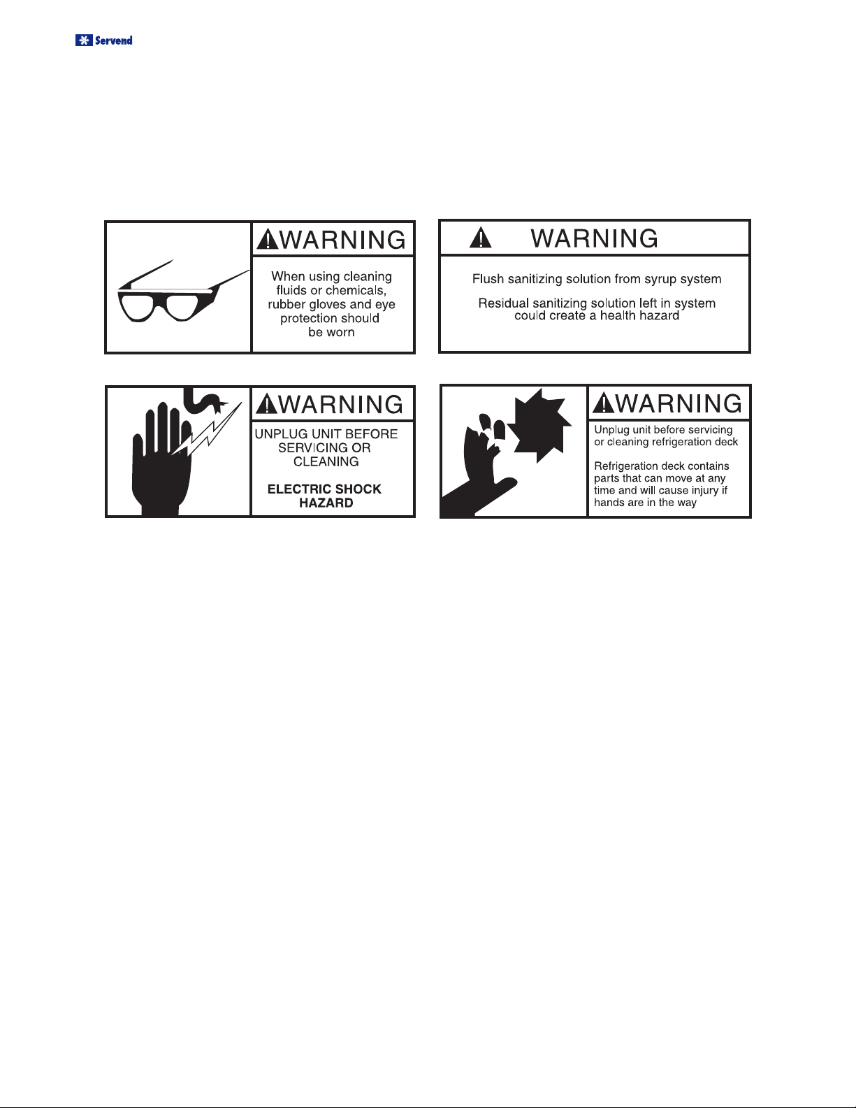
SAFETY INSTRUCTIONS
Installation and start-up of this equipment should be done by a qualified service technician. Operation,
maintenance, and cleaning information in this manual are provided for the user/operator of the equipment.
DAILY CHECK LIST FOR THE OPERATOR
• Check CO
the primary regulator gauge will point to a shaded
area that reads “Low CO2” or “Change CO2 Cylinder.”
• Check Syrup supply.
supply. If CO2 supply is low, an arrow on
2
• Clean drain pan, grid, and splash panel. See daily
cleaning instructions on page 18.
• Clean the valve nozzles and diffusers. See daily
cleaning instructions on page 18.
4
Revision July 22, 2003
5010146
Page 4

Installation and Service Manual
TABLE OF CONTENTS
FOREWORD ........................................................................................................ 3
UNPACKING AND INSPECTION ........................................................................ 3
WARRANTY INFORMATION ............................................................................... 3
SAFETY INSTRUCTIONS ................................................................................... 4
DAILY CHECK LIST FOR THE OPERATOR....................................................... 4
CED SERIES BEVERAGE DISPENSERS OVERVIEW ...................................... 7
COUNTER-ELECTRIC DESCRIPTION .................................................................................. 7
INTERNAL COLD (IC) CARBONATOR CED ......................................................................... 7
EXTERNAL CARBONATOR (EC) CED ................................................................................. 7
NON-CARBONATED CED .................................................................................................... 7
EQUIPMENT OVERVIEW .................................................................................... 8
INTERNAL COLD (IC) CARBONATOR ................................................................................. 8
EXTERNAL CARBONATOR (EC) ......................................................................................... 9
NON-CARBONATED UNITS ................................................................................................. 9
INSTALLATION OVERVIEW ............................................................................... 9
BIB INSTALLATION DIAGRAM ........................................................................................... 10
SELECTING LOCATIONS ..................................................................................11
ALL CEDS........................................................................................................................... 11
PLACING UNIT IN THE OPERATING POSITION ................................................................ 11
COUNTER MOUNT ............................................................................................................. 11
ISLAND MOUNT ................................................................................................................. 12
REFRIGERATION SYSTEM START.................................................................. 13
INCOMING WATER SUPPLY REQUIREMENTS ................................................................. 13
CONNECTING THE DRAIN PAN HOSE .............................................................................. 13
CONNECTING WATER SUPPLY LINE(S) TO THE CED ................................. 14
INTERNAL CARBONATOR ................................................................................................. 14
EXTERNAL CARBONATOR ............................................................................................... 14
NONCARBONATED UNIT................................................................................................... 14
5010146
Revision July 22, 2003
5
Page 5

Installation and Service Manual
TABLE OF CONTENTS
CONNECTING SYRUP SUPPLY LINES TO ALL CEDS ................................... 14
CONNECTING CO2 SUPPLY LINE TO THE CED ............................................ 15
CED WITH INTERNAL CARBONATOR ............................................................................... 15
CED WITH EXTERNAL CARBONATOR ............................................................................. 15
NON-CARBONATED CED .................................................................................................. 15
SPECIFICATIONS FOR CED SERIES DISPENSERS ...................................... 16
CED - 30 SPECIFICATIONS ................................................................................................ 16
SPECIFICATIONS FOR CED SERIES DISPENSERS ...................................... 17
CED - 40 SPECIFICATIONS ................................................................................................ 17
OPERATION ...................................................................................................... 18
BAG-IN-BOX (BIB) START-UP ............................................................................................ 18
INSTALL DECALS .............................................................................................................. 18
CLEAN UP .......................................................................................................................... 18
SANITIZING AND CLEANING.......................................................................... 18
DAILY CLEANING ...............................................................................................................18
WATER BATH ..................................................................................................................... 18
PERIODIC SANITIZING OF THE DISPENSER .................................................................... 18
BAG-IN-BOX ....................................................................................................................... 19
FIGAL SYSTEM SANITIZING .............................................................................................. 19
CARBONATED/NON-CARBONATED CONVERSION...................................... 20
WIRING DIAGRAM 120 VOLT/60/1 ................................................................... 22
INTERNAL CARBONATOR ................................................................................................ 22
EXTERNAL CARBONATOR ............................................................................................... 22
WIRING DIAGRAM 220-240 VOLT/50/1 ........................................................... 23
INTERNAL CARBONATOR ................................................................................................. 23
EXTERNAL CARBONATOR ............................................................................................... 23
WIRING DIAGRAM 208-230 VOLT/60/1 ........................................................... 24
INTERNAL CARBONATOR ................................................................................................. 24
EXTERNAL CARBONATOR ............................................................................................... 24
TROUBLESHOOTING GUIDE........................................................................... 25
6
Revision July 22, 2003
5010146
Page 6
Installation and Service Manual
CED SERIES BEVERAGE DISPENSERS OVERVIEW
IMPORTANT: TO THE USER OF THIS SERVICE MANUAL, THIS MANUAL IS A GUIDE FOR
INSTALLING THIS EQUIPMENT. REFER TO THE TABLE OF CONTENTS FOR PAGE LOCATION
FOR DETAILED INFORMATION PERTAINING TO QUESTIONS THAT ARISE DURING
INSTALLATION AND START-UP OF THIS EQUIPMENT.
This section gives the Counter-Electric Dispenser description, theory of operation, and service data for
the 6 and 8 flavor Post Mix Dispensers (hereafter referred to as CED.)
COUNTER-ELECTRIC DESCRIPTION
The CED s are small compact chillers with a high-impact and corrosion-resistant stainless steel housing and
may be island mounted or installed on a front or rear
counter. The refrigeration assemblies are the drop-intype that can be removed for service and maintenance.
Adjustable syrup flow regulators, located on the dispensing valves, are easily accessible to control the Water to
INTERNAL COLD (IC) CARBONATOR
CED
This CED Unit is equipped with a 1/3 H.P. refrigeration
assembly and has a built-in cold carbonator. The carbonator is located on the deck of the CED under the
bonnet. The carbonator tank is located within the water
tank. Installation requirements for operation are: Placement of CED on a countertop making sure the unit is
level, installation of loose shipped parts, connection of
drains, connection of plain water and syrup supplies,
adjustment of CO2 regulators, fill water tank with water,
and plug CED power cord into an electrical outlet.
EXTERNAL CARBONATOR (EC) CED
(Requires Connection to a Remote Carbonator)
This CED is equipped with a 1/3 H.P. refrigeration assembly and requires connection to an external Carbonator. Installation requirements for operation are: Placement of CED on a countertop making sure the unit is
level, installation of loose shipped parts, connection of
drain, connection of external carbonator, connection of
plain water and syrup supplies, adjustment of CO2 regulators, fill water tank with water, and plug CED power
cord into an electrical outlet.
Syrup Ratio (Termed Brix) of the dispensed product. All
CEDs have electric dispensing valves.
5010146
Revision July 22, 2003
NON-CARBONATED CED
This CED is the same as the external carbonator unit,
except no carbonator is required. Installation requirements for operation are: Placement of CED on a
countertop making sure it is level, installation of loose
shipped parts, connection of drains, connection of plain
water including a booster system if necessary, syrup/
juice supplies, possible adjustment of CO2 regulators,
filling water tank with water, and plugging CED power
cord into an electrical outlet.
7
Page 7
Installation and Service Manual
EQUIPMENT OVERVIEW
NOTE: BEFORE SHIPPING, STORING, OR RELOCATING THIS CED, THE SYRUP SYSTEMS MUST
BE SANITIZED AND ALL SANITIZING SOLUTION MUST BE PURGED FROM THE SYRUP
SYSTEMS. ALL WATER MUST ALSO BE PURGED FROM THE PLAIN AND CARBONATED WATER
SYSTEMS. A FREEZING AMBIENT ENVIRONMENT WILL CAUSE RESIDUAL WATER IN THE CED
TO FREEZE CAUSING EXPANSION OF TUBING AND RESULTING IN DAMAGE TO INTERNAL
COMPONENTS.
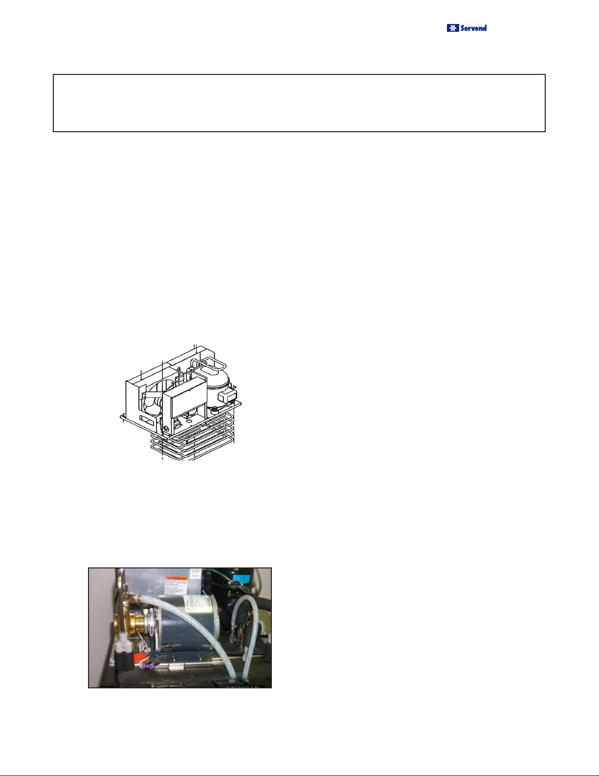
INTERNAL COLD (IC) CARBONATOR
The CED 30 is a 6 valve unit set up to dispense a noncarbonated drink from the NO. 3 dispensing valve. The
CED 40 is an 8 valve unit set up to dispense a noncarbonated drink from the No. 4 and 5 valves. The remaining dispensing valves on each unit are set to dispense
carbonated beverages. Refer to the instructions on
page 21-22 to convert a valve from carbonated to noncarbonated or non-carbonated to carbonated.
A CO2 cylinder delivers carbon dioxide (CO2) gas through
adjustable CO2 regulator to the syrup BIB pump and also
to an internal carbonator. Plain water also enters the
internal carbonator tank, and is carbonated by the regulated CO2 gas pressure. When a dispensing valve is
opened, CO2 pressure exerted within the syrup BIB pump
propels syrup from the BIB, through the CED Unit beverage coils, and into the dispensing valve. Carbonated
water is forced from the carbonator tank by CO2 pressure which pushes cold carbonated water into the dispensing valve resulting in a carbonated drink being dispensed. A noncarbonated drink is dispensed in the same
manner as a carbonated drink with the exception that
plain water is substituted for carbonated.
The carbonator is replenished when the carbonated
water level inside the tank drops, which in turn automatically starts the carbonator water pump. When the water
level inside the tank has been replenished, carbonator
water pump will stop.
8
Revision July 22, 2003
5010146
Page 8
EQUIPMENT OVERVIEW
Installation and Service Manual
EXTERNAL CARBONATOR (EC)
The CED 30 is a 6 valve unit set up to dispense a noncarbonated drink from the No. 3 dispensing valve. The
CED 40 is an 8 valve unit set up to dispense a noncarbonated drink from the No. 4 and 5 valves. The remaining dispensing valves on each unit are set to dispense
carbonated beverages. Refer to the instructions on
page 21-22 to convert a valve from a carbonated to
non-carbonated or from non-carbonated to carbonated.
A CO2 cylinder delivers carbon dioxide (CO2) gas through
adjustable CO2 regulators to the syrup BIB pump and
also to an external carbonator. Plain water also enters
the remote carbonator tank, and is carbonated by the
regulated CO2 gas pressure. When a dispensing valve
is opened, CO2 pressure exerted within the syrup BIB
pump propels syrup from the BIB, through the CED beverage coils, and into the dispensing valve. Carbonated
water is forced from the carbonator tank by CO2 pressure which pushes carbonated water through the CED
cooling coils, and into the dispensing valve. Syrup and
carbonated water meet simultaneously and mix at the
nozzle of the dispensing valve resulting in a carbonated
drink being dispensed. A noncarbonated drink is dispensed in the same manner as a carbonated drink with
the exception that plain water is substituted for carbonated.
INSTALLATION
OVERVIEW
This section covers unpacking, inspecting, selecting location, installing the CED, and preparing for
operation.
1. After the unit has been unpacked, remove the keys.
The key will be needed to perform brixing of valves.
Hold onto the keys until such time to forward them
to the respective owner/operator. Remove tape
(which secures grid in place in drain pan) from
grid and other packing material.
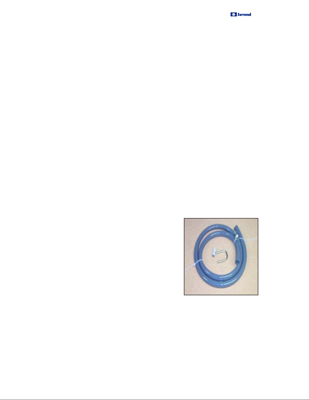
2. Make sure all items are present and in good condition. Loose shipped items in the carton include
the drain kit parts, S/S “U” tube, John Guest fitting
and the instructions.
3. Inspect CED for any external damages.
The Carbonator is replenished when the carbonated
water level inside the tank drops, which in turn automatically starts the carbonator water pump. When the water
level inside the tank has been replenished, carbonator
water pump will stop.
NON-CARBONATED UNITS
A CO2 cylinder delivers carbon dioxide (CO2) gas through
adjustable CO2 regulators to the syrup/juice BIB pump. When
a dispensing valve is activated, pressure exerted upon the
syrup BIB pump propels syrup/concentrate from the BIB,
through the cooling coils, and into the dispensing valve. Plain
water enters the CED and passes through the cooling coils
to the dispensing valve. Syrup/concentrate and plain water
meet simultaneously in the dispensing valve and mix at the
nozzle resulting in a still (noncarbonated) drink being dispensed. For noncarbonated BIB syrup(s)/concentrate(s) to
be delivered at ambient temperature, refer to the conversion
instructions for bypassing the cooling coil.
5010146
Revision July 22, 2003
9
Page 9

Installation and Service Manual
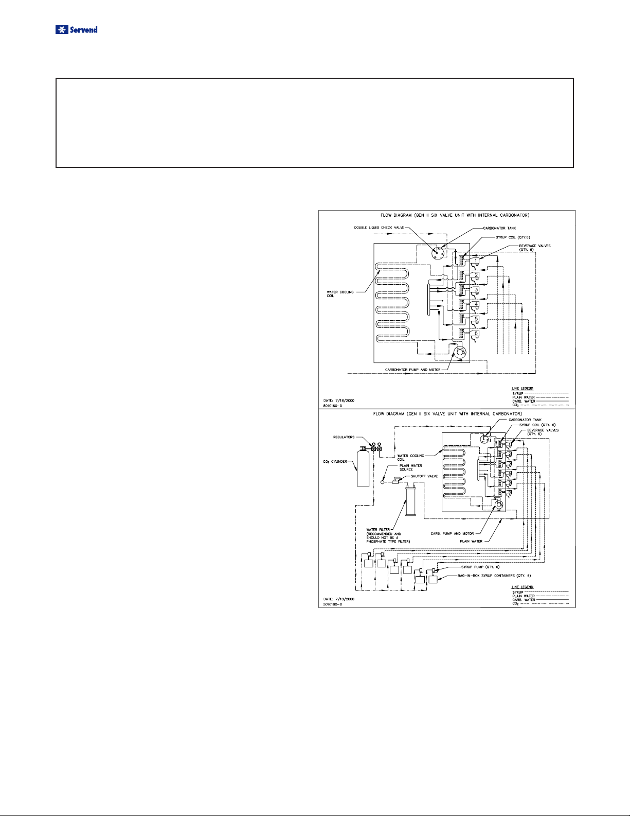
BIB INSTALLATION DIAGRAM
The internal carbonator in the post-mix system has two inlets and one outlet connection. The internal
carbonator is pre-plumbed at the factory. The inlets for CO2 and water are located behind the splash panel.
There are two inlets for water and one inlet for CO2. If you have questions refer to the plumbing diagram on
your equipment.
The outlet of the syrup supply (either BIB pump or Figal tank) connects to the appropriate syrup inlet fitting. The
syrup flows through the icebath to be chilled on its way to the valves. The water flows through the icebath to the
internal carbonator then back through the icebath chilling the carbonated water on its way to the valves. When both
fluids leave the beverage valve they are mixed in the nozzle of the valve. Out comes a properly cooled, properly
ratioed soft drink.
When starting a new beverage system of either type, be sure the electrically operated valves are turned off. Assure
all connections are made, turn the water supply on to the dispenser. Open CO2 tank valve and set all pressures.
Turn the refrigeration on and allow the refrigeration coils to fill with ice. After the beverage has achieved a 40
degree F temperature, the ratio of the syrup-to-water (brix) on a post-mix system may then be set.
10
Revision July 22, 2003
5010146
Page 10

SELECTING LOCATIONS
Installation and Service Manual
The CED may be island-mounted or installed on a front
or rear counter. Locate the CED so the following requirements are satisfied: CED is for indoor use only and must
NOT be placed in an area where a water jet or similar
high pressure sprayer could be used.
1. CED must be installed near a properly grounded
electrical outlet with proper electrical requirements
fused at proper amperage or circuit connected
through an equivalent HACR circuit breaker with
ELCB (GFCI). REFER TO UNIT NAMEPLATE FOR
THE REQUIRED POWER CIRCUIT OPERATING
VOLTAGE. Hz AND THE MINIMUM CIRCUIT
AMPACITY OF THE CED. No other electrical equipment should be connected to this circuit. ALL ELECTRICAL WIRING MUST CONFORM TO NATIONAL
AND LOCAL ELECTRICAL CODES. MAIN PLUG
MUST BE ACCESSIBLE FOR DISCONNECTION.
The key switch is able to be mounted on either side
of the CED. When the location for the CED is selected, make sure the key switch is mounted where
it will be most accessible.
2. CED must be open at the top and on both sides with
at least 6-inches clearance at the rear. CED has top
air outlet and is to remain free of all objects. Do not
place anything on top of the CED . The rear grill of
the CED must be unobstructed to allow air to enter
the hood.
3. Place CED close to a permanent drain in order to
route the drain pan hose to the permanent drain.
Water tank overflow hose goes into the drain pan.
ALL CEDS
Remove the Bonnet by removing the two screws
holding it in place.
PLACING UNIT IN THE OPERATING
POSITION
The CED must be level horizontally from right to left and
front to rear.
CED inlet supply lines, power cord, and drain pan hose
must either be routed out of the CED
COUNTER MOUNT
Place the CED in location on the countertop. Route CED
inlet supply lines, power cord, and drain pan hose out of
the base back access hole. Area around inlet supply
lines at flanged hole behind front access panel must be
closed and sealed.
Unit base back access hole, or if island-mounted, through
a hole cut in the countertop under the CED Unit. Proceed to applicable installation procedure.
5010146
Revision July 22, 2003
To comply with NSF requirements within the United
States, the CED base must be sealed to the countertop
unless the optional 4” legs are installed (see above).
All access holes to the base must be sealed. If the 4”
legs are installed, proceed to step E, otherwise proceed
as follows to seal the CED base.
11
Page 11

Installation and Service Manual
ISLAND MOUNT
SELECTING LOCATIONS
Place the CED in location on the countertop flush with the
countertop edge. Mark CED’s center line on the edge of
the countertop, then move the CED to one side. Starting at
the center line mark on the edge of the countertop, measure back 12-inches for the location of a hole at least 4
inches to be cut into the countertop. Cut at least a 4 inch
hole in the countertop where indicated. Place the CED in
position over the hole. Route the inlet supply lines, power
cord, and drain pan hose down through the hole in the
countertop. Install the line outlet plug, provided with the
CED in the base back access hole. The area around the
inlet supply lines at the flanged hole behind the front access panel must be closed and sealed.
A. Tilt CED up to expose bottom of base.
B. Liberally apply silastic sealant such as Dow
Corning RTV 731 or equivalent on the base
bottom edges.
C. Lower the CED into operating position on the
counter top to complete the seal of the base to
the countertop.
Note: Do not move CED after positioning or the seal
between the base and the countertop will be broken.
Fill Water Tank and Start Refrigeration System
1. Make sure the plug in the water tank drain hose is
secure.
2. Remove the plug from the water fill hole located on
the carbonator pump deck. Fill the water tank with
clean water until water flows out of the tank overflow. Use a funnel if necessary. Caution: Be care-
ful not to spill water on any electrical fitting or
connection. Do not use distilled water.
Note: An alternative method to fill the water tank
would be to temporarily splice the incoming water
line into the water tank drain hose, turn on the water
and fill the tank until water comes out the overflow
drain. Turn off the water and plug the water tank drain
hose.
D. Apply additional sealant around the bottom of
the base. The seal must be a minimum of 1/4
inch to prevent crevices and to ensure a complete seal.
E. Close and seal all access holes to the inside
of the CED base.
12
3. Install plug in water fill hole.
4. Place CED refrigeration system switch and the agitation switch, located on the side of the control box, in
“OFF” position ON A CED WITH AN INTERNAL COLD
CARBONATOR, DISCONNECT THE POWER SUPPLY TO THE CARBONATOR AT THIS POINT. OTHERWISE WATER PUMP DAMAGE WILL OCCUR.
5010146
Revision July 22, 2003
Page 12

REFRIGERATION SYSTEM START
WARNING: CED must be electrically grounded to avoid
possible fatal electrical shock or serious injury to the operator. 120V CED power cord is equipped with a threeprong plug. If supply cord is damaged it must be replaced
by the manufacturer or its service agent or a similarly
qualified person in order to avoid a hazard. If a grounded
electrical outlet is not available, use an approved method
to ground the CED.
A. Plug CED power cord into an accessible properly
grounded electrical outlet.
Installation and Service Manual
INCOMING WATER SUPPLY
REQUIREMENTS
NOTE: SerVend International Inc. recommends that
a water shutoff valve and water filter be installed
in the incoming water supply line.
The incoming water source to the equipment shall be
installed with adequate backflow protection to comply with applicable National, State, and local codes.
Water pressure should be a minimum of 45 PSI or
you will starve the pump of water and damage it.
The maximum water pressure should be 55 psi or
you will affect the quality of the carbonation.
The carbonator pump should be located within 6
feet of a 1/2 inch water source. A minimum 3/8 inch
ID water line must be used. Before connection the
water source should be flushed of approximately 5
gallons of water to purge the system of any sediments, especially in areas of new construction.
B. Place CED refrigeration system switch and agita-
tion switch located on the side of the control box, in
“ON” position. Compressor, condenser fan motor,
and agitator motor will start and begin forming an
ice bank. NOTE: The refrigeration system on the
50 Hz CED is equipped with a 4-minute time delay. Whenever power to the compressor is interrupted, the time delay will take effect. When a full
ice bank has been formed, the compressor and condenser fan motor will stop, but the agitator motor
will continue to operate, circulating ice bath water in
the water tank. Turn the key switch to the “ON” position to check all beverage valves for operation.
Check for water, syrup, and CO2 leaks in the supply
system. Replace the bonnet with the two screws
provided.
Recommended: Beverage pour temperature should be maintained at a constant 40o F or below for optimum brixing value.
Time required to reach the proper temperature will be subject
to water and ambient air temperatures.
CONNECTING THE DRAIN PAN HOSE
NOTE: Connection of the drain pan hose to a permanent drain is recommended. A drain pan hose
routed to a waste container is not recommended
due to sanitation problems.
1. Remove the plug from the drain pan nipple.
2. Connect drain pan hose to the nipple on the drain pan.
3. Install drain pan in position on the CED, then place grid in
the drain pan.
4. Route lower end of drain pan hose to a permanent drain
and connect according to local codes.
NOTE: If no permanent drain is available the drain pan
may be emptied manually. Some CED’s come equipped
with a drain pan that may be removed by sliding it forward. Nothing else needs to be removed to take the
drain pan off, empty it and replace it on the CED. If this
drain pan is hooked to a permanent drain, the drain nipple
must be opened and connected to the drain hose as
described on page 12 of this manual.
5010146
Revision July 22, 2003
13
Page 13

Installation and Service Manual
CONNECTING WATER SUPPLY LINE(S) TO THE CED
INTERNAL CARBONATOR
Connect plain water supply line to the CED at the plain
water inlet line, and the non-carbonated water inlet.
EXTERNAL CARBONATOR
Connect carbonated water supply line from the external
carbonator to the CED at the carbonated water inlet
line.
Connect plain water supply line to the CED at the noncarbonated water inlet line.
NONCARBONATED UNIT
Connect plain water supply lines to the CED at the plain
water inlet line and the non-carbonated water inlet.
CONNECTING SYRUP SUPPLY
LINES TO ALL CEDS
Connect syrup supply lines to the CED at the corresponding syrup inlet lines. Syrup inlet line #1 will correspond
with the right hand dispensing valve. The valves are
numbered in sequence from right to left.
14
Revision July 22, 2003
5010146
Page 14

Installation and Service Manual
CONNECTING CO2 SUPPLY LINE TO THE CED
CED WITH INTERNAL
CARBONATOR
1. Connect CO2 supply to the CO2 inlet at the CED.
2. Open pressure relief valve. (Red arm should be in
the upright position).
3. Turn water supply on and fill the carbonator tank until
water can be seen coming out the pressure relief
valve.
4. Close the pressure relief valve.
5. Activate a dispensing valve until a good flow of plain
water is established.
6. Check for water leaks.
7. Turn on the CO
psi.
8. Activate a valve until all the water has been forced
out of the system by the CO2.
9. Check for any leaks.
10. Connect the power to the carbonator.
bottle and adjust the regulator to 75
2
CED WITH EXTERNAL
CARBONATOR
1. Connect CO2 supply to the CO2 inlet on the carbonator tank.
2. Connect carbonated water outlet line to the dispensing system. To avoid contamination of potable liquids, do not connect copper tubing or fittings between
the discharge fitting on the carbonator and the dispensing valve.
3. Open pressure relief valve. (Red arm should be in
the upright position).
4. Turn water supply on and fill the carbonator tank until
water can be seen coming out the pressure relief
valve.
5. Close the pressure relief valve.
6. Activate a dispensing valve until a good flow of plain
water is established.
7. Check for water leaks.
8. Turn on the CO
100 psi.
bottle and adjust the regulator to
2
11. Operate the valves until the carbonator cycles
several times and there is a good flow of carbonated water from each valve.
9. Activate a valve until all the water has been forced
out of the system by the CO2.
10. Check for any leaks.
11. Plug in the carbonator.
12. Operate the valves until the carbonator cycles
several times.
NON-CARBONATED CED
1. Open plain water inlet supply line shutoff valve.
Check for water leaks and tighten any loose connections.
2. Operate each dispensing valve until the system is
flushed and water flows smoothly from each valve.
5010146
Revision July 22, 2003
15
Page 15
Installation and Service Manual
SPECIFICATIONS FOR CED SERIES DISPENSERS
CED - 30 SPECIFICATIONS
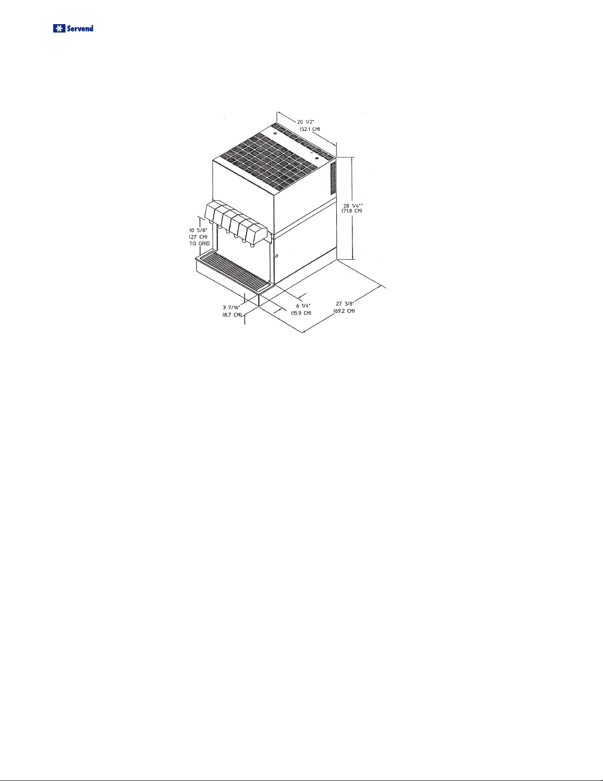
Dimensions:
20 1/2” W x 27 3/8” D x 28 1/4” H
51.435 cm W x 69.53 cm D x 72.4 cm H
Ice Bank Size:
30 lbs/13.636 kg
Valves:
Six beverage valves
Standard Voltage:
120/60/1
6 - foot (1.82m) three-wire cord and plug
provided.
Fuse Size:
Minimum 20 amp
Amperage:
8.2 Operating amps
13 FLA
Other voltage available:
220/240 Volts - 50 Hz - 1 Ph
208/230 Volts - 60 Hz - 1 Ph
Fuse Size:
Minimum 10 amp
Amperage:
4.5 Operating amps
6.5 FLA
Compressor:
1/3 HP
50 Hz refrigeration system is equipped
with a four minute time delay.
Refrigerant:
R-134a
120 V Unit 8.5 oz.
208/230 V Unit 7.75 oz.
220/240 V Unit 11 oz.
Always check serial plate for exact charge
Ship Weight:
EC Approximately 143 lbs/65 kg.
IC Approximately 158 lbs/71.8 kg
Cabinet:
Stainless Steel
Drain:
Single pre-installed 3/4” PVC (NPT) drain
fitting extends from the drain pan.
Service:
Beverage valves, inlet connections, drain
connection, and electrical components
are front accessible.
Optimum Ambient Conditions are:
Between 50 o and 95oF (10oC and 35oC).
16
Revision July 22, 2003
5010146
Page 16

Installation and Service Manual
SPECIFICATIONS FOR CED SERIES DISPENSERS
CED - 40 SPECIFICATIONS
Dimensions:
25 1/4” W x 27 3/8” D x 28 1/4” H
63.1 cm W x 69.53 cm D x 72.4 cm H
Ice Bank Size:
Up to 40 lbs/18.182 kg
Valves:
Eight beverage valves
Standard Voltage:
120/60/1
6 - foot (1.82m) three-wire cord and plug
provided.
Fuse Size:
Minimum 20 amp
Amperage:
8.2 Operating amps
13 FLA
Other Voltage Available:
208/230 Volts -60 Hz - 1 Ph
Fuse Size:
Minimum 10 amp
Amperage:
4.5 Operating amps
6.5 FLA
Compressor:
1/3 HP
Refrigerant:
R-134a
120 V Unit 11 oz.
208/230 V Unit 10.25 oz
Always check serial plate for exact charge.
Ship Weight:
EC Approximately 160 lbs/72.7 kg.
IC Approximately 175 lbs/79.5 kg
Cabinet:
Stainless Steel
Drain:
Single pre-installed 3/4” PVC (NPT) drain
fitting extends from the drain pan.
Service:
Beverage valves, inlet connections, drain
connection, and electrical components
are front accessible.
Optimum Ambient Conditions are:
Between 50 o and 95oF (10oC and 35oC).
5010146
Revision July 22, 2003
17
Page 17

Installation and Service Manual
OPERATION
BAG-IN-BOX (BIB) START-UP
All lines should be properly flushed and sanitized before
starting the CED. Sanitizing instructions can be found beginning on page 18 of the Installation Manual.
1. Connect each BIB connector to the appropriate BIB.
2. Gradually adjust the secondary regulator to 70 psi. Never
run a BIB pump without the BIB installed as the pump
could be damaged. Set final secondary regulator pressure 70 -75 psi depending on the line size and the distance of the run.
3. Operate each dispensing valve until the syrup flows
smoothly from the valve.
Adjust Syrup to Water Ratio (Brix) of Dispensed Product.
1. Adjust water flow rate on each dispensing valve to
2.5 ounces per second.
2. Adjust dispensing valves for water-to-syrup ratio (brix) as
recommended by the syrup distributor.
INSTALL DECALS
Install decals (provided with CED ) on the dispensing valve
covers.
DAILY CLEANING
• Drain pan
• Grid
• Splash Panel
• Valve Nozzles
• Diffusers
You will need: Warm clean water, a mild nonabrasive
soap, and a clean cloth.
1. Lift the grid and remove it from the drain pan.
2. Using warm water, mild soap, and a clean cloth, wash
the drain pan and splash panel. After cleaning, rinse
with clean, warm water.
3. Allow plenty of warm (not hot) tap water to run down
the drain of the drain pan to remove any syrup residue
that can clog the drain opening.
4. Wash the grid, then rinse with clean water. Place
the grid back in the drain pan.
5. Wash all exterior surfaces of the CED with warm
water and a clean cloth. Wipe again with a clean,
dry cloth.
6. Remove the nozzles and diffusers from the dispensing valves.
7. Clean both the nozzles and the diffusers with soap and
water to remove syrup residue, then rinse with warm,
clean water.
8. Replace the diffusers and the nozzles on the valves.
CLEAN UP
Clean up all work areas. Dispose of all packing material, excess tubing and trash properly.
SANITIZING AND CLEANING
Note: Scheduled cleaning must be in compliance with local
health codes. The CED must not be cleaned with a water jet.
This cleaning schedule is a recommendation.
WATER BATH
It is recommended that the water bath be drained at least
twice a year. Turn off the refrigeration. Completely melt the
ice bank. Refill the water bath with fresh water until water
runs out the overflow tube. Turn on the refrigeration.
PERIODIC SANITIZING OF THE
DISPENSER
Note: Sanitize the dispenser at initial start-up in addition
to periodic sanitizing.
18
Revision July 22, 2003
5010146
Page 18

Installation and Service Manual
BAG-IN-BOX
BEVERAGE SYSTEM SANITIZING
(for trained personnel only)
You will need: Three clean, empty five-gallon buckets to be
used for the rinse, detergent, and sanitizing buckets, and a container to be placed under soda valves to carry away detergent
and sanitizing agents which will be flushed through the valves.
1. Disconnect the bag-in-box connectors.
2. Prepare the following in three clean buckets:
A. Rinse bucket - fill bucket with clean tap water.
(Refill as necessary.)
B. Detergent bucket - mix approved beverage
system cleaner with warm water as recommended.
C. Sanitizing bucket - mix a solution of 1 ounce
of liquid, unscented household bleach (5.25%
Cl Na O concentration) with two gallons of tap
water. The mixture should supply 200 PPM of
available chlorine.
3. Remove the cap located opposite the tubing connection
on the bag-in-box connector.
4. Place bag-in-box connector in rinse bucket (step 2A). Draw
clean tap water through the system and out the beverage
valve until all syrup is flushed from the system.
5. Place bag-in-box-connector in the detergent bucket (step
2B). Draw detergent solution through the system and out
the beverage valve for 2 minutes. Then, allow the remaining detergent to stay in the system for 5 minutes.
6. Remove the valve nozzle and diffuser, as described in the
daily cleaning instructions. Using a clean cloth or a soft
brush, scrub the nozzle, the diffuser, the bottom of the dispensing valve, and the cup lever, if applicable.
7. Place the valve diffuser and nozzle in sanitizing solution for
20 minutes, then replace them on the beverage valve.
8. Place bag-in-box connector in the sanitizing bucket (step
2C). Draw sanitizing solution through the system and out
the valve for 5 minutes. Allow the sanitizing solution to
remain in the system for a minimum of 20 minutes.
9. Place the bag-in-box connector in the rinse bucket (step
2A). Draw clean rinse water through the system and out
the valve for 2 minutes, flushing the sanitizing solution from
the system.
10.Repeat Step 8 and Step 9.
11. Replace the plastic cap opposite the tubing connection on
the bag-in-box connector.
12.Reconnect the bag-in-box connector to the beverage syrup
bag-in-box.
13.Repeat the above steps for each beverage valve, or follow
this procedure with any number of valves concurrently.
FIGAL SYSTEM SANITIZING
1. Prepare the following in three clean Figal tanks:
a Rinse tank - fill with room temperature water.
b Detergent tank - mix approved beverage system
cleaner with warm water as directed.
c Sanitizing tank - mix a solution of 1 ounce of
unscented household bleach (5.25% Cl Na O
concentration) to two gallons of tap water. The
mixture should supply 200 PPM available chlorine.
2. Locate the Figal syrup tank for the circuit to be sanitized. Remove both quick disconnects from the Figal syrup tank. Rinse quick disconnects in warm tap
water.
3. Connect rinse tank to the syrup line. Draw clean rinse
water through the valve until syrup is flushed from
the system.
4. Connect detergent tank to the syrup line and draw
detergent through the valve for 2 minutes. Then, allow remaining detergent to stay in the system for 5
minutes.
5. Follow steps 6 and 7 in the bag-in-box sanitizing instructions to clean and sanitize the beverage valve
nozzle and diffuser.
6. Connect sanitizing tank to the syrup line and draw
sanitizing solutions through the valve for 5 minutes.
Allow sanitizing solution to remain in the system for a
minimum of 20 minutes.
7. Connect rinse tank to the syrup line. Draw clean rinse
water through the system for two minutes to flush
the sanitizing solution from the system.
8. Repeat Step 6 and Step 7.
9. Reconnect syrup lines.
5010146
Revision July 22, 2003
19
Page 19

Installation and Service Manual
CARBONATED/NON-CARBONATED CONVERSION
To change a valve from carbonated to non-carbonated:
1. Turn off the water and CO2 to the CED.
2. Disconnect the syrup box to the valve you want
to change.
3. Bleed the pressure from the valve.
4. Remove the plug from the back of the John
Guest ”Y” fitting on the non-carbonated water
line behind valve #4.
5. Remove the plug from the back of the John
Guest ”Y” fitting on the carbonated water line
behind valve #3.
6. Install the stainless steel “U” tube between the
2 John Guest “Y” fittings.
7. Remove the carbonated water supply line from the
back of the John Guest “Y” fitting behind valve #3.
8. Install a plug into the “Y” fitting.
9. Install a John Guest union and plug on the carbonated water supply line that was removed from the
“Y” fitting.
10.Turn on the water and CO2 to the CED.
11.Follow the sanitizing instructions to clean the old
syrup from the line.
12.Hook up a fresh box of the syrup to be used.
13.Set the valve to the proper ratio of syrup to water.
14CED 40 converts the same way between valve num-
bers 5 & 6.
20
Revision July 22, 2003
5010146
Page 20

Installation and Service Manual
CARBONATED/NON-CARBONATED CONVERSION
To change a valve from non-carbonated to carbonated:
1. Turn off the water and CO2 to the CED.
2. Disconnect the syrup box to the valve you want to
change.
3. Bleed the pressure from the valve.
4. Remove the John Guest union and plug from the
carbonated water line that is stubbed
out behind valve #4.
5. Remove the plain water line from the John Guest
“Y” fitting going into valve #4.
6. Install the union and plug removed from the carbonated water line into the plain water line.
7. Insert the carbonated water line into the John Guest
“Y” fitting behind the #4 valve.
8. Turn on the water and CO2 to the CED.
9. Follow the sanitizing instructions to clean the old
syrup from the line.
10.Hook up a fresh box of the syrup to be used.
11.Set the valve to the proper ratio of syrup to water.
12,CED-40 converts the same way, but the valve num-
bers are 4 & 5.
5010146
Revision July 22, 2003
21
Page 21

Installation and Service Manual
WIRING DIAGRAM 120 VOLT/60/1
INTERNAL CARBONATOR
EXTERNAL CARBONATOR
22
Revision July 22, 2003
5010146
Page 22

Installation and Service Manual
WIRING DIAGRAM 220-240 VOLT/50/1
INTERNAL CARBONATOR
EXTERNAL CARBONATOR
5010146
Revision July 22, 2003
23
Page 23

Installation and Service Manual
WIRING DIAGRAM 208-230 VOLT/60/1
INTERNAL CARBONATOR
EXTERNAL CARBONATOR
24
Revision July 22, 2003
5010146
Page 24

TROUBLESHOOTING GUIDE
NOITIDNOC NOITAGITSEVNI KCEHC NOITCERROC
Installation and Service Manual
sknirdmraW?gninnurrosserpmocehtsI
.metsysnoitaregirfer
.ffohctiwsrewoP"no"othctiwsevoM
.oN
lortnocknabecIlortnocecalper/kcehC
daolrevorosserpmoCdaolrevoecalper/kcehC
yalertratSyalerecalper/kcehC
rosserpmoCecalper/kcehC
?gninnurrosserpmocehtsI
.seY
ytridresnednoCretlifrianaelC
dekcolbresnednoCnoitcurtsboevomeR
gninnurtonnaFrotomnafecalpeR
noitatigAoNrellepmiecalper/kcehC
wolleveltnaregirfeRhtiwegrahc,kaelriapeR
noitisop
)BetoNees(
rosserpmoc
tnaregirferehtdeneposimetsysnoitaregirferehtemitynatahtrebmemerottnatropmisitI:AetoN
ehtotnidehgiewtnaregirferfoegrahcreporpehtdnadellatsnireirdwena,derevocerebdluohs
noitatigaecalper/kcehC
rotom
.tnaregirfer AetoneeS
.evoba
sagropurys,retawoN
.gnisnepsid
?hctiws
?hctiws
?nezorftinusIwollevelretaWhtabecillifer/kcehC
.tinUDECeht
?tinuehtotrewoperehtsIrewopoNteserrotinunigulP
yekhguorhtgnimocrewopsI
yekehtotrewoperehtsI
"ffo"hctiwsyeK"no"hctiwsyeknruT
evitcefedhctiwsyeKhctiwsyekecalpeR
ehthguorhtrewopoN
remrofsnart
lortnocknabecI.lortnocecalper/kcehC
rekaerb
remrofsnartecalper/teseR
.wolebBetoNeeS
7dna5seborpneewtebecnatsiserehtkcehctsumuoylortnocknabeciehtkcehcotredronI:BetoN
detcetedsismhoK54nahtsselecnatsiseranehwtratslliwtinunoitaregirferehT.7&6neewtebdna
lliwhcihw,seborpehtllasrevocknabeciehtnehwpotslliwtinunoitaregirferehT.7&5seborpssorca
reporpehtsretsigereborpehtfI.7&6seborpneewtebsmhoK58nahtretaergecnatsiseraetaerc
seodeborpehtfI.eludomlortnocehtecalper,dilossezeerfroetaregirfert'nowDECehtdnaecnatsiser
knabeciehT.eludomlortnocknabeciehtdnaeborpehtecalper,ecnatsiserreporpehtretsigerton
tuohtiwdecalperebyamtI.kcednoitaregirferehtnoxoblortnocehtnidetnuomsieludomlortnoc
ehtgnivomerybdesseccaebyameborplortnocknabeciehT.htabretawehtmorfeborpehtgnivomer
morfkcednoitaregirferehtgnivomertuohtiwdevomerdnadewahtebnaceborpehT.kcedrotanobrac
5010146
Revision July 22, 2003
25
Page 25

Installation and Service Manual
TROUBLESHOOTING GUIDE
NOITIDNOC
gnisnepsidylnoretaWerusserpoNfotuo)s(rotalugeR
-AGITSEVNI
NOIT
KCEHC NOITCERROC
)s(rotalugertsujda/kcehC
tnemtsujda
OCfotuO
2
knathserfllatsnI
)s(rotalugerevitcefeD)s(rotalugerecalper/riaper/kcehC
OC
2
detcurtsbo
OCdnapuryS
ylno
2
gnisnepsid
rotanobraCrewopoNrotanobracnigulP.ylppusrewopkcehC
rodeknik,dehcnipenil
OCecalper/riaper/kcehC
enil
2
.rekaerbteserro
ylppusretaW"no"denrutsiretawerusekaM
retlifretawecalpeR
reniartspmupecalper/naelc/kcehC
evlavkcehcretawriaper/naelc/kcehC
.enilretawnezorfrofkcehC lanretnI
.ylnotinurotanobraC
rotanobracevitcefeD,pmuprotanobracecalper/riaper/kcehC
.lortnocleveldiuqilroedortcele,rotom
gnisnepsidylnopurySretaw/adossI
lortnocknabecievitcefeD.lortnocknabeciecalpeR .BetoneeS
?nezorfenil
retawnialpdnapuryS
gnisnepsidylno
erusserpoNOCfotuO
2
fotuorotalugerPH
knathserfllatsnI
gnittesreporpehtotrotalugerPHtsujdA
tnemtsujda
rotalugerPHevitcefeDrotalugerPHecalper/riaper/kcehC
OC
2
detcurtsbo
tonlliwevlavenO
gnihtynaesnepsid
rewoperehtsI
?evlavehtot
noitcennoc
rodeknik,dehcnipenil
esoolroeriwnekorB
OCecalper/riaper/kcehC
enil
2
rotcennocroeriwriaper/ecalpeR
hctiwsorcimdaBhctiwsorcimecalpeR
teewsootsi
desnepsidegareveB
?tcerroc
)xirb(oitarehtsI
knirdehtfo
OCwoL
2
skael
fotuolortnocwolF
lortnocwolfehttsujdA
tnemtsujda
oteudwolfadostneiciffusnI
erusserprotanobracwol
oteuderusserp
roretawehtninoitcurtsbO
OCtsujdA
2
OCriapeR
skael
2
knatehtegnahcroerusserp
senilehttuonaelC
enilados
hguone
teewstonsiegareveB
?tcerroc
)xirb(oitarehtsI
knirdehtfo
tnemtsujda
fotuolortnocwolF
hgihootwolfadoSOCteseR
lortnocwolfehttsujdA
2
yrassecenfi
rotalugerecalperroerusserp
enilpurysninoitcurtsbOenilpurysehttuonaelC
gnimaoferasknirDmetsyserA
serusserp
?tcerroc
noitanobracrevOOCkcehC
sevlav/senilytriDmetsyseritneezitinas/naelC
2
yrassecenfirotalugerecalper
roerusserpteseR.ylppus
26
Revision July 22, 2003
5010146
Page 26

Manitowoc Beverage Equipment
2100 Future Drive w Sellersburg, IN 47172-1868
Tel: 812.246.7000, 800.367.4233 Fax: 812.246.9922
www.manitowocbeverage.com
In accordance with our policy of continuous product development and
improvement, this information is subject to change at any time without notice.
5010146 Revision July 22, 2003
 Loading...