

Page 1

DE EN
Abbildungen 14 - 17
Ersatzteile 18 - 19
Bauanleitung 5
Assembly instructions 9
Illustrations 14 - 17
Replacement parts 18 - 19
FR
ES
Notice de montage 13
Illustrations 14 - 17
Pièces de rechanges 18 - 19
Instrucciones de montaje 27
Ilustraciónes 14 - 17
Repuestos 18 - 19
Erhältliche Varianten | Available versions
Version disponible | Varianti disponibili
Variantes disponibles
© Copyright by MULTIPLEX Modellsport GmbH & Co. KG 2018
# 1-00846
IT
Istruzioni di montaggio 23
Illustrazioni 14 - 17
Parti di ricambio 18 - 19
Page 2
Sicherheitshinweise für MULTIPLEX-Flugmodelle
Beim Betrieb des Modells sind alle Warn- und Sicherheitshin-
DE
weise der Betriebsanleitung unbedingt zu beachten.
Das Modell ist KEIN SPIELZEUG im üblichen Sinne. Benutzen Sie Ihr
Modell mit Verstand und Vorsicht, und es wird Ihnen und Ihren Zuschauern
viel Spaß bereiten, ohne eine Gefahr darzustellen. Wenn Sie Ihr Modell
nicht verantwortungsbewusst betreiben, kann dies zu erheblichen
Sachbeschädigungen und schwerwiegenden Verletzungen führen. Sie
alleine sind dafür verantwortlich, dass die Betriebsanleitung befolgt und
die Sicherheitshinweise in die Tat umgesetzt werden.
Mit Inbetriebnahme des Modells erklärt der Betreiber, dass er den Inhalt der
Betriebsanleitung, besonders zu Sicherheitshinweisen, Wartungsarbeiten,
Betriebsbeschränkungen und Mängeln kennt und verstanden hat.
Dieses Modell darf nicht von Kindern unter 14 Jahren betrieben
werden. Betreiben Minderjährige das Modell unter der Aufsicht eines
fürsorgepichtigen und sachkundigen Erwachsenen im Sinne des
Gesetzes, ist dieser für die Umsetzung der Hinweise der Betriebsanleitung
verantwortlich.
DAS MODELL UND DAZUGEHÖRIGES ZUBEHÖR MUSS VON KINDERN
UNTER 3 JAHREN FERNGEHALTEN WERDEN! ABNEHMBARE KLEINTEILE
DES MODELLS KÖNNEN VON KINDERN UNTER 3 JAHREN VERSCHLUCKT
WERDEN. ERSTICKUNGSGEFAHR!
Die Multiplex Modellsport GmbH & Co. KG ist nicht haftungspichtig für
Verluste, Beschädigungen und Folgeschäden jeder Art, die aufgrund
falschen Betriebs, nicht bestimmungsgemäßer Verwendung oder
Missbrauchs dieses Produkts, einschließlich der damit verwendeten
Zubehörteile entstehen.
• Das Modell darf nicht unter Einuss von Alkohol und anderen Rauschmitteln betrieben werden. Gleiches gilt für Medikamente, die das
Wahrnehmungs- und Reaktionsvermögen beeinträchtigen.
• Fliegen Sie nur bei Wind- und Wetterverhältnissen, bei denen Sie
das Modell sicher beherrschen können. Berücksichtigen Sie auch bei
schwachem Wind, dass sich Wirbel an Objekten bilden und auf das
Modell Einuss nehmen können.
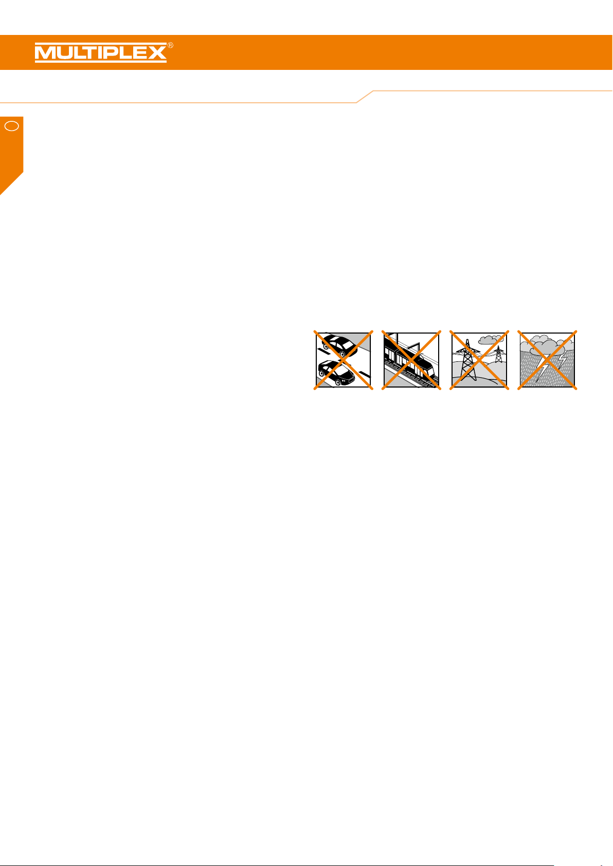
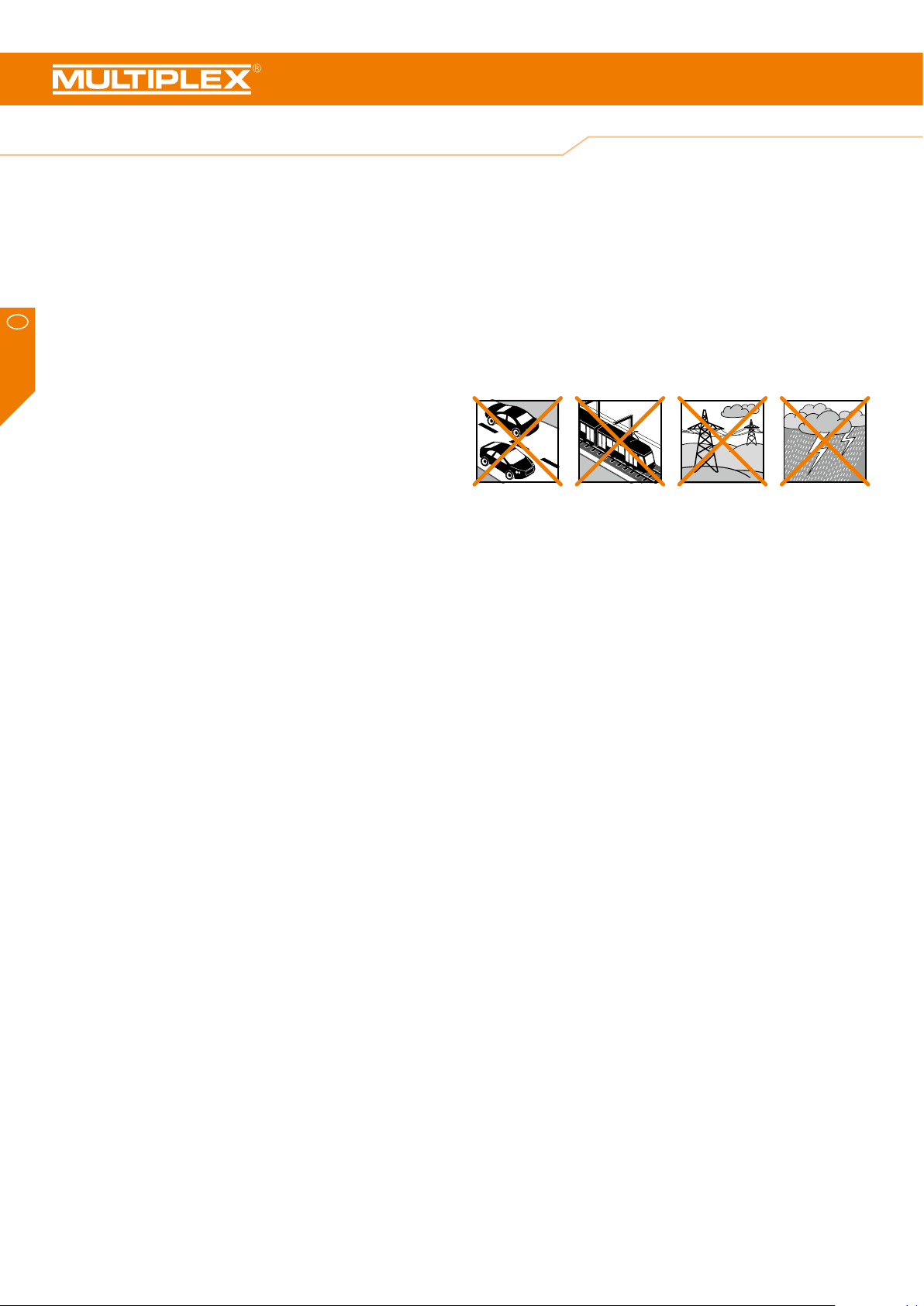
• Fliegen Sie nie an Orten, an denen Sie andere oder sich selbst gefährden, z.B. in Wohngebieten, an Überlandleitungen, Straßen und
Bahngleisen.
• Niemals auf Personen und Tiere zuiegen! Vermeiden Sie unnötige
Risiken und weisen Sie auch andere Piloten auf mögliche Gefahren
hin. Fliegen Sie immer so, dass weder Sie noch andere in Gefahr kommen – auch langjährige, unfallfreie Flugpraxis ist keine Garantie für
die nächste Flugminute.
Restrisiken
Auch wenn das Modell vorschriftsmäßig und unter Beachtung aller
Sicherheitsaspekte betrieben wird, besteht immer ein Restrisiko.
Eine Haftpichtversicherung (Modellugzeug mit Antrieb) ist daher
obligatorisch. Falls Sie Mitglied in einem Verein oder Verband sind,
können Sie ggf. dort eine entsprechende Versicherung abschließen.
Bestimmungsgemäße Verwendung
Das Modell darf ausschließlich im Hobbybereich verwendet werden. Jede
andere Art der Verwendung ist nicht erlaubt. Zum Betrieb des Modells
darf nur das von Multiplex empfohlene Zubehör verwendet werden. Die
empfohlenen Komponenten sind erprobt und auf eine sichere Funktion
passend zum Modell abgestimmt. Werden andere Komponenten
verwendet oder das Modell verändert, erlöschen sämtliche etwaigen
Ansprüche gegenüber Hersteller bzw. Vertreiber.
Um das Risiko beim Betrieb des Modells zu minimieren, beachten Sie
insb. folgende Punkte:
• Das Modell wird über eine Funkfernsteuerung gelenkt. Keine Funkfernsteuerung ist sicher vor Funkstörungen. Störungen können zum
Kontrollverlust über das Modell führen. Achten Sie deshalb beim Betrieb des Modells jederzeit und unbedingt auf große Sicherheitsräume
in alle Richtungen. Schon beim kleinsten Anzeichen von Funkstörungen ist der Betrieb des Modells sofort einzustellen!
• Das Modell darf erst in Betrieb genommen werden, nachdem ein
kompletter Funktions- und Reichweitentest gemäß der Anleitung der
Fernsteuerung erfolgreich ausgeführt wurde.
• Das Modell darf nur bei guten Sichtverhältnissen geogen werden.
Fliegen Sie nicht bei schwierigen Lichtverhältnissen und nicht in Richtung der Sonne, um Blendungen zu vermeiden.
Achten Sie jederzeit auf die Wartung und den ordnungsgemäßen Zustand
von Modellen und Fernsteuerung.
Aufgrund der Bauweise und Ausführung des Modells können insb.
folgende Gefahren auftreten:
Verletzungen durch die Luftschraube: Sobald der Akku angeschlossen
ist, ist der Bereich um die Luftschraube freizuhalten. Beachten Sie, dass
Gegenstände vor der Luftschraube angesaugt oder dahinter weggeblasen
werden können. Richten Sie das Modell immer so aus, dass es sich im
Falle eines ungewollten Anlaufens des Motors nicht in Richtung anderer
Personen bewegen kann. Bei Einstellarbeiten, bei denen der Motor läuft
oder anlaufen kann, muss das Modell stets von einem Helfer sicher
festgehalten werden.
• Absturz durch Steuerfehler: Auch dem erfahrensten Piloten können
Fehler unterlaufen. Fliegen Sie daher stets nur in sicherer Umgebung
und auf zugelassenen Modelluggeländen.
• Absturz durch technisches Versagen oder unentdeckten Transportoder Vorschaden: Das Modell ist vor jedem Flug unbedingt sorgfältig
zu überprüfen. Rechnen Sie jederzeit damit, dass es zu technischem
oder Materialversagen kommen kann. Betreiben Sie das Modell daher
stets nur in sicherer Umgebung.
• Betriebsgrenzen einhalten: Übermäßig hartes Fliegen schwächt die
Struktur des Modells und kann plötzlich oder aufgrund von „schlei-
2
Page 3
Sicherheitshinweise für MULTIPLEX-Flugmodelle
chenden“ Folgeschäden bei späteren Flügen zu technischem und Materialversagen und Abstürzen führen.
• Feuergefahr durch Fehlfunktion der Elektronik: Akkus sind sicher
aufzubewahren. Sicherheitshinweise der Elektronikkomponenten im
Modell, des Akkus und des Ladegeräts sind zu beachten. Elektronik
ist vor Wasser zu schützen. Regler und Akkus müssen ausreichend
gekühlt werden.
Die Anleitungen unserer Produkte dürfen nicht ohne ausdrückliche Erlaubnis der Multiplex Modellsport GmbH & Co. KG
(in schriftlicher Form) - auch nicht auszugsweise in Print- oder
elektronischen Medien reproduziert und / oder veröffentlicht
werden.
Sicherheitshinweise für MULTIPLEX-Bausätze
Machen Sie sich mit dem Bausatz vertraut!
MULTIPLEX-Modellbaukästen unterliegen während der Produktion
einer ständigen Materialkontrolle. Wir hoffen, dass Sie mit dem
Baukasteninhalt zufrieden sind. Wir bitten Sie dennoch, alle Teile (nach
Stückliste) vor Verwendung zu prüfen, da bearbeitete Teile vom Umtausch
ausgeschlossen sind. Sollte ein Bauteil einmal nicht in Ordnung sein, sind
wir nach Überprüfung gern zur Nachbesserung oder zum Umtausch bereit.
Bitte senden Sie das Teil ausreichend frankiert an unseren Service. Fügen
Sie unbedingt den Kaufbeleg und eine kurze Fehlerbeschreibung bei. Wir
arbeiten ständig an der technischen Weiterentwicklung unserer Modelle.
Änderungen des Baukasteninhalts in Form, Maß, Technik, Material und
Ausstattung behalten wir uns jederzeit und ohne Ankündigung vor. Bitte
haben Sie Verständnis dafür, dass aus Angaben und Abbildungen dieser
Anleitung keine Ansprüche abgeleitet werden können.
Dieses Modell ist nicht aus Styropor™! Daher sind Verklebungen mit
Weißleim, Polyurethan oder Epoxy nicht möglich.Diese Kleber haften
nur oberächlich und können im Ernstfall abplatzen. Verwenden Sie nur
Cyanacrylat-/Sekundenkleber mittlerer Viskosität, vorzugsweise ZackiELAPOR® # 85 2727, der für ELAPOR® Partikelschaum optimierte und
angepasste Sekundenkleber. Bei Verwendung von Zacki-ELAPOR®
können Sie auf Kicker oder Aktivator weitgehend verzichten. Wenn
Sie jedoch andere Kleber verwenden, und auf Kicker/Aktivator nicht
verzichten können, sprühen Sie aus gesundheitlichen Gründen nur im
Freien. Vorsicht beim Arbeiten mit allen Cyanacrylatklebern. Diese Kleber
härten u. U. in Sekunden, daher nicht mit den Fingern und anderen
Körperteilen in Verbindung bringen. Zum Schutz der Augen unbedingt
Schutzbrille tragen! Von Kindern fernhalten! An einigen Stellen ist es auch
möglich Heißkleber zu verwenden. Hierauf weisen wir in der Anleitung
ggf. hin!
DE
Achtung!
Ferngesteuerte Modelle, insbesondere Flugmodelle, sind kein
Spielzeug im üblichen Sinne. Ihr Bau und Betrieb erfordert
technisches Verständnis, ein Mindestmaß an handwerklicher
Sorgfalt sowie Disziplin und Sicherheitsbewusstsein. Fehler und
Nachlässigkeiten beim Bau und Betrieb können Personen- und
Sachschäden zur Folge haben. Da der Hersteller keinen Einfuss
auf ordnungsgemäßen Zusammenbau, Wartung und Betrieb hat,
weisen wir ausdrücklich auf diese Gefahren hin.
Warnung:
Wie jedes Flugzeug hat das Modell statische Grenzen! Sturzüge und
unsinnige Manöver können zum Verlust des Modells führen. Beachten Sie:
In solchen Fällen gibt es von uns keinen Ersatz. Tasten Sie sich vorsichtig
an die Grenzen heran. Das Modell ist auf den von uns empfohlenen
Antrieb ausgelegt, kann den Belastungen aber nur standhalten, wenn es
einwandfrei gebaut und unbeschädigt ist.
Krumm – gibt es eigentlich nicht. Falls Einzelteile z.B. beim Transport
verbogen wurden, können sie wieder gerichtet werden. Dabei verhält sich
ELAPOR® ähnlich wie Metall. Wenn Sie es etwas überbiegen, federt das
Material ein Stück zurück und behält dann seine Form. Das Material hat
natürlich seine Grenzen – übertreiben Sie also nicht!
Krumm – gibt es schon! Wenn Sie Ihr Modell lackieren wollen
benötigen Sie bei Verwendung der EC-Color Farben keinen Primer zur
Vorbehandlung Optisch bringen Mattlacke das beste Ergebnis. Die
Lackschichten dürfen keinesfalls zu dick oder ungleichmäßig aufgetragen
werden, sonst verzieht sich das Modell und wird krumm, schwer oder
sogar unbrauchbar!
Arbeiten mit Zacki-ELAPOR®
Zacki-ELAPOR® wurde speziell für die Verklebung für unsere
Schaummodelle aus ELAPOR® entwickelt. Um die Verklebung möglichst
optimal zu gestalten, sollten Sie folgende Punkte beachten:
• Vermeiden Sie den Einsatz von Aktivator. Durch ihn wird die Verbindung deutlich geschwächt. Vor allem bei großächiger Verklebung
empfehlen wir, die Teile 24 Stunden trocken zu lassen.
• Aktivator ist lediglich zum punktuellen Fixieren zu verwenden. Sprühen Sie nur wenig Aktivator einseitig auf. Lassen Sie den Aktivator
ca. 30 Sekunden ablüften.
• Für eine optimale Verklebung rauen Sie die Oberäche mit einem
Schleifpapier (320er Körnung) an.
# 85 2727
3
Page 4
Zubehör und Werkzeug
Benötigtes Zubehör Optionales Zubehör
DE
®
• 1x Zacki Elapor
• 1x Empfänger RX-5 light M-LINK 2,4 GHz # 55 808
• 1x Akku ROXXY EVO LiPo 3 - 2600M 40C # 316656
Zum Bau des Modells benötigen Sie folgendes Werkzeug
• Aktivatorspray für CA-Kleber
• mittelgroßer Kreuzschlitzschraubendreher
• Inbusschlüssel 1,5
• 10mm Gabel- oder Steckschlüssel
• Schleifpapier der Körnung 220-320
20g # 85 2727
• WINGSTABI 7-Channel # 5 5010
• WINGSTABI RX-7-DR M-LINK # 5 5012
• Empfänger RX-7-DR M-LINK 2,4 GHz # 5 5811
• Multiplex G-Raten Sensor für M-LINK # 8 5409
• Propeller-Wuchtgerät # 33 2355
• Dekorbogen blau-rot # 1-00856
• Dekorbogen gelb-silber # 1-01012
Lieferumfang AcroMaster PRO RR
®
• ELAPOR
• Antriebsmotor Roxxy BL C35-48-990kv
• Regler Roxxy BL-Control 755 S-BEC
• Propeller 12x6“
• 2 Servos HS-82 MG
• 2 Servos HS-65 HB
-Modell (fast fertig gebaut)
Technische Daten
Spannweite: 1100 mm
Länge über alles: 1150 mm
Fluggewicht: ca. 1350 g
Flächeninhalt: 36,6 dm²
Flächenbelastung: 36,9 g/dm²
RC-Funktionen: Querruder, Höhenruder, Motor, Seitenruder
Stückliste AcroMaster PRO
lfd. Nr Stück Bezeichnung Material Abmessungen
1 1 Bauanleitung Papier DIN A4
2 1 Reklamationsmeldung Modelle Papier DIN A4
3 1 Anleitung ROXXY BL-control 755 S-BEC Papier DIN A4
4 1 Rumpf fertig montiert Elapor Fertigteil
5 1 Tragäche links fertig montiert Elapor Fertigteil
6 2 Tragäche rechts fertig montiert Elapor Fertigteil
7 1 Höhenleitwerk fertig montiert Elapor Fertigteil
8 1 Kabinenhaube fertig montiert / lackiert Elapor Fertigteil
9 1 Seitenruder fertig montiert Elapor Fertigteil
10 1 Halter für Spinner Kunststoff Fertigteil
11 1 Spinner EPP Ø 62 mm
12 1 Hauptholm CFK Ø 10x620 mm
13 1 Hilfsholm CFK Ø 10x200 mm
14 1 Tragflächensicherung Holz Fertigteil
15 1 Akkubrett Holz Fertigteil
16 1 Fahrwerk fertig montiert Alu / Kunststoff Fertigteil
17 2 selbstschneidende Schrauben Stahl, verzinkt Ø 2,9x16 mm
18 1 Luftschraube Faserverstärkter Kunststoff Ø 12x6"
19 1 Luftschraubenkupplung Aluminium Ø 5/6 mm
20 3 Klettband Pilzkopf Kunststoff 25x60 mm
21 3 Klettband Velours Kunststoff 25x60 mm
22 2 Klettschlaufe Kunststoff Fertigteil
4
Page 5
Bauanleitung
Vor dem Bau
Überprüfen Sie die gelieferten Teile auf ihre Vollständigkeit mittels der
Stückliste auf Seite 4 und
Wir empfehlen eine weiche, saubere und gerade Unterlage, damit das
Modell beim Bau keine Macken bekommt. Verwenden Sie, wenn nicht
ausdrücklich anders angegeben, zum Verkleben des Modells Zacki
ELAPOR
1. Montage des Höhenleitwerks
Schieben sie das Höhenleitwerk 7 hinten in den Rumpf 4 ein und
überprüfen Sie die Passung und den rechtwinkligen Sitz. Ziehen Sie es
wieder nach hinten raus und schleifen Sie es an den Kontaktächen
etwas an, damit der Kleber später besser haftet. Überprüfen Sie den Sitz
erneut. Sind Sie zufrieden, geben Sie auf die Rumpfseite Zacki ELAPOR®
an und schieben Sie das Höhenleitwerk nal ein
ggf. mit einem Papiertuch überquellenden Klebstoff ab. Achten Sie auf
den rechtwinkligen Sitz und ebenfalls darauf, dass die Längen A und B
identisch sind
Prozess.
Stellen Sie mittels Fernsteuerung das Höhenruderservo in neutrale
Position. Stellen Sie die Höhenruderklappe ebenfalls in neutrale Position
und schrauben Sie das Gestänge am Höhenruderhorn fest.
®
CA-Sekundenkleber.
Abb. 04 + 05
Abb. 01 + 02
. Wenig Aktivatorspray beschleunigt den
.
Abb. 03
. Wischen
Sie
Schieben Sie die Unterlegscheibe auf und drehen Sie die Mutter auf
Abb. 11
Spinner ⓫ auf den Halter.
6. Montage des Empfängers
Stecken Sie die Servostecker in den Empfänger und befestigen Sie diesen
mit dem Klettband ⓴ und ㉑ im auf der dafür vorgesehenen Fläche im
Rumpf
1 Querruder links; 2 Höhenruder; 3 Seitenruder; 4 Motor; 5 Querruder rechts
7. Montage des Akkus
Kletten Sie den Akku mit einem Klettband ⓴ und ㉑ auf das Akkubrett
Abb. 15
Schieben Sie den Akku in die Akkuschiene ein
Sie diese ebenfalls mit einem Stück Klettband ⓴ und ㉑, sowie einer
Klettschlaufe ㉒. Die Klettschlaufe wird dazu in den Schlitz im Akkubrett
und im Elapor durchgefädelt und fest gespannt
8. Vorflugkontrolle und Schwerpunkt
Kontrollieren Sie das Modell, bevor Sie es das erste Mal iegen lassen.
Folgende Punkte müssen vor dem ersten Flug überprüft werden:
. Ziehen Sie die Mutter gut fest. Stecken Sie zum Schluss den
Abb. 12
. Die Beschriftungen auf den Servosteckern sind folgende:
und spannen Sie eine Klettschlaufe ㉒ um beides
Abb. 15
. und befestigen
.
Abb. 14
Abb. 13
DE
.
2. Montage des Seitenruders
Gehen Sie beim Seitenruder analog zum Höhenleitwerk vor. D.h. erst den
Sitz überprüfen, dann anschleifen, Kleber angeben & ausrichten
Achten Sie auch hier auf einen rechtwinkligen Sitz
Stellen Sie mittels Fernsteuerung das Seitenruderservo in neutrale
Position. Stellen Sie die Seitenruderklappe ebenfalls in neutrale Position
und schrauben Sie das Gestänge am Seitenruderhorn fest.
3. Montage des Fahrwerks
Schrauben Sie das Fahrwerk ⓰ mit den selbstschneidenden Schrauben
an den Rumpf
⓱
4. Montage der Tragflächen an den Rumpf
Das lange CFK-Rohr ⓬ ist der hintere Hauptholm und das kurze CFKRohr ⓭ ist der vordere Hilfsholm. Schieben Sie die Holme in eine
Tragäche und diese in den Rumpf. Schieben Sie die andere Tragäche
nun auf und achten Sie dabei darauf, dass die Servokabel beide nach
oben in den Rumpf geführt werden
der Tragächen die Tragächensicherung ⓮ von oben in die Schlitze der
beiden Tragächen
5. Montage des Propellers
Stecken Sie die Luftschraubenkupplung ⓳ bis zum Anschlag
auf die Motorwelle. Wuchten Sie den Propeller ⓲ z.B. mit dem
Propellerwuchtgerät # 33 2355 oder ähnlichem. Schieben sie den
Propeller auf und danach den Halter für den Spinner ⓾.
Abb. 08
Abb. 10
.
Abb. 09
.
Abb. 07
. Stecken Sie zum Sichern
Abb. 06
.
.
• Ruderhörner fest
• Servoschrauben fest (Kreuzschlitzschrauben)
• Anlenkgestänge fest (Inbus-Madenschrauben)
• Prüfen Sie den Rundlauf des Spinners, indem Sie den Propeller von
Hand drehen
Der Akku (3S 2600 mAh 40C) und Empfänger wird so im Modell
positioniert und mittels Klettband und Klettschlaufe xiert, dass der
Schwerpunkt rumpfseitig bei 110 mm hinter der Nasenleiste liegt
Abb. 16
9. Ruderausschläge
Einstellungen normal
Einstellungen 3D
10. Erstflug
Machen Sie einen Reichweitentest und vergewissern Sie sich, dass alle
Ruder richtig herum laufen und auf neutraler Position stehen. Starten Sie
das Modell vom Boden und machen Sie sich in großer Höhe mit den
Flugeigenschaften vertraut.
.
Ruderwege 40% Expo Einhängepunkte
Querruder +/- 30mm Servo ganz innen Ruderhorn außen
Höhenruder +/- 40mm Servo ganz innen Ruderhorn außen
Seitenruder +/- 55mm Servo ganz innen Ruderhorn außen
Ruderwege 60% Expo Einhängepunkte
Querruder +/- 50mm Servo 2.Loch von außen Ruderhorn außen
Höhenruder +/- 60mm Servo ganz außen Ruderhorn mitte
Seitenruder +/- 85mm Servo ganz außen Ruderhorn mitte
5
Page 6
Safety information for MULTIPLEX airplane models
When operating the model, all warning and safety information in
the operating instructions must be observed.
The model is NOT A TOY in the conventional sense. If you use your model
carefully, it will provide you and your spectators with lots of fun without
posing any danger. If you do not operate your model responsibly, this may
lead to signicant property damage and severe injury. You and you alone
are responsible for following the operating instructions and for ensuring
EN
the safety guidelines are adhered to.
When setting up the model, operators declare they are familiar with
and understand the contents of the operating instructions, particularly
regarding safety information, maintenance work, operating restrictions,
and deciencies.
This model may not be operated by children under the age of 14. If minors
operate the model under the supervision of a responsible and competent
adult pursuant to the law, this person is responsible for adhering to the
information in the operating instructions.
THE MODEL AND THE ASSOCIATED ACCESSORIES MUST BE KEPT OUT
OF REACH OF CHILDREN UNDER 3 YEARS OF AGE! CHILDREN UNDER 3
COULD SWALLOW REMOVABLE SMALL PARTS OF THE MODEL. RISK OF
SUFFOCATION!
Multiplex Modellsport GmbH & Co. KG is not liable for loss, damage
and consequential damage of any kind caused by incorrect operation,
improper use or misuse of this product, including the accessories used
along with it.
• Only y the model in wind and weather conditions in which you can
safely control it. Even with light wind, take into account that turbulence
may build up on objects and have an effect on the model.
• Never y in places where this would pose a danger to others, i.e. in
residential areas, near power lines, roads, and railroad tracks.
• Never direct the model at people or animals! Avoid unnecessary risks
and alert other pilots to potential hazards. Always y in a manner that
ensures neither you nor others are exposed to danger – even many
years of accident-free ying experience are no guarantee for the next
minute of ying time.
Residual risks
Even if the model is operated in accordance with the regulations and
observing all safety aspects, there is always a residual risk.
Third-party liability insurance (powered model airplane) is therefore
mandatory. If you are a member of a group or association, you might be
able to take out the appropriate insurance there.
Ensure models and the remote control are properly maintained and are in
good condition at all times.
Proper use
The model may only be used in the hobby sector. No other type of use
is permitted. To operate the model, only the accessories recommended
by Multiplex may be used. The recommended components have been
tested and adjusted for safe functioning together with the model. If other
components are used or the model is modied, all claims against the
manufacturer or retailer are void.
In order to minimize the risk when operating the model, observe the
following points in particular:
• The model is controlled via a remote control. No remote control is
safe from radio interference. Interference may lead to a loss of control
of the model. Therefore, always ensure large safety distances in all
directions when operating the model. As soon as even the smallest
indication of radio interference presents itself, operation of the model
must be halted immediately!
• The model may only be put into operation after a complete function
and range test has been successfully carried out as per the instructions for the remote control.
• The model may only be own in good visibility. Do not y in poor light
or in the direction of the sun in order to avoid glare.
• The model may not be operated under the inuence of alcohol or other
intoxicants. The same applies for medicines that impair perception and
responsiveness.
Due to the construction and design of the model, the following dangers
may arise in particular:
Injuries caused by the propeller: As soon as the battery is connected, the
area around the propeller must be kept clear. Be aware that objects in
front of the propeller may be sucked in and objects behind the propeller
may be blown away. Always align the model ensuring it cannot move in
the direction of other people if the motor starts up unintentionally. When
performing adjustments for which the motor is running or may start up,
the model must always be securely held in place by a helper.
• Crashes caused by control errors: Even the most experienced pilots
can make mistakes. For this reason, only y in a safe environment and
at authorized model airplane ying elds.
• Crashes caused by technical failures, undetected damage from
transportation or pre-existing damage: The model must be carefully
inspected before each ight. Bear in mind that technical or material
failures may occur at any time. Therefore, only operate the model in a
safe environment.
• Adhere to operating limits: Excessively harsh ying weakens the structure of the model and may lead to technical and material failures as
well as crashes immediately or, due to 'insidious' consequential damage, in later ights.
• Risk of re due to malfunction of the electronics: Batteries must be
stored safely. The safety information of the electronic components in
the model, the battery, and the charging device must be observed.
6
Page 7

Safety information for MULTIPLEX airplane models
The electronics must be protected from water. The controller and the
batteries must be sufciently cooled.
The instructions of our products may not be reproduced and/or
published – not even in part – in print or electronic media without
the express (written) permission of Multiplex Modellsport GmbH
& Co. KG.
Safety information for MULTIPLEX construction kits
Familiarize yourself with the construction kit!
MULTIPLEX model kits are subjected to constant material inspection
during production. We hope that you are satised with the contents of the
kit. We nevertheless ask that you check all parts (according to the parts
list) before use, as used parts cannot be exchanged. If a part is not OK,
we will be happy to x or replace it after verifying this. Please send the
part with sufcient postage to our Service department. Be sure to include
a short description of the fault along with the purchase receipt. We are
continuously working on further developing the technology of our models.
We reserve the right to make changes to the contents of the kit in terms
of shape, dimension, technology, material, and equipment at any time and
without warning. Please understand that no claims can be derived from
specications and illustrations in these instructions.
Caution!
Remote-controlled models, particularly airplane models, are not
toys in the conventional sense. Their construction and operation
requires technical understanding, a minimum level of artisan
skills, discipline, and safety-awareness. Errors and negligences
during building and operation may result in personal injury or
property damage. As the manufacturer has no influence on
proper assembly, maintenance, and operation, we explicitly refer
to these dangers.
This model is not made of Styrofoam™! Therefore, adhesions using
white glue, polyurethane or epoxy are not possible. These glues only stick
supercially and may peel off in severe cases. Only use cyanoacrylate/
superglue of medium viscosity, preferably Zacki-ELAPOR® # 85 2727,
the superglue optimized and adapted for ELAPOR® particle foam. When
using Zacki-ELAPOR®, you can largely do without kickers or activators. If,
however, you use other adhesives, and are unable to do without kickers/
activators, only spray outdoors for health reasons. Take care when working
with all cyanoacrylate adhesives. These adhesives sometimes harden in
seconds, so do not bring your ngers or other body parts into contact
with them. To protect your eyes, be sure to wear protective goggles!
Keep away from children! In some places, hot glue may also be used. If
applicable, this is indicated in the instructions!
Working with Zacki ELAPOR®
Zacki ELAPOR® was developed specially for adhesion on our foam
models made of ELAPOR®. In order to design the adhesion as optimally
as possible, the following points should be taken into consideration:
• Avoid the use of activators. This causes the bonding to be signicantly
weakened. Especially for large-scale adhesion, we recommend allowing 24 hours for the parts to dry.
• Activators must only be used for point xing. Only spray a little activator on one side. Allow the activator to ash off for approx. 30 seconds.
EN
Warning:
Like any airplane, the model has static limitations! Nosedives and reckless
maneuvers may result in damage to the model. Please note: In such
cases, there is no replacement. Approach the limitations with caution.
The model is tted with the propeller recommended by us but can only
withstand the loads if it is built awlessly and is undamaged.
Crooked – does not really exist. If individual parts are bent during
transit, they can be straightened again. Here, ELAPOR® behaves like
metal. If you overbend the material slightly, it springs back minimally and
retains its shape. The material of course has its limits – so don’t overdo it!
Crooked – does indeed exist! If you want to paint your model, you do
not need any primer for pretreatment when using the EC colors. Matt
paints result in the best look. Under no circumstances may the paint coats
be too thick or applied unevenly, otherwise the model will go out of shape
and will be crooked, heavy or even unusable!
• For optimal bonding, sand down the surface using sandpaper (grain
size 320).
# 85 2727
7
Page 8
Accessories and tools
Required accessories Optional accessories
®
• 1x Zacki Elapor
• 1x receiver RX-5 light M-LINK 2.4 GHz # 55 808
• 1x battery ROXXY EVO LiPo 3 - 2600M 40C # 316656
The following tools are required to assemble the model:
EN
• Activator spray for CA adhesive
• Medium-sized cross-tip screwdriver
• Hex wrench 1.5
• 10 mm open-ended wrench or socket wrench
• 220-320 grit sandpaper
20 g # 85 2727
Scope of delivery AcroMaster PRO RR
• ELAPOR® model (almost fully assembled)
• Drive motor Roxxy BL C35-48-990kv
• Controller Roxxy BL Control 755 S-BEC
• 12x6“ propeller
• 2 servos HS-82 MG
• 2 servos HS-65 HB
• WINGSTABI 7-channel # 5 5010
• WINGSTABI RX-7-DR M-LINK # 5 5012
• Receiver RX-7-DR M-LINK 2.4 GHz # 5 5811
• Multiplex G sensor for M-LINK # 8 5409
• Propeller balancer # 33 2355
• Decal sheet blue-red # 1-00856
• Decal sheet yellow-silver # 1-01012
Specications
Wingspan: 1100 mm
Overall length: 1150 mm
Flight weight: Approx. 1350 g
Wing area: 36.6 dm²
Wing loading: 36.9 g/dm²
RC functions: Aileron, elevator, motor, rudder
List of parts AcroMaster PRO
Part No.
1 1 Assembly instructions Paper DIN A4
2 1 Complaints form for models Paper DIN A4
3 1 ROXXY BL-Control 755 S-BEC instructions Paper DIN A4
4 1 Fuselage fully assembled Elapor Finished component
5 1 Left wing fully assembled Elapor Finished component
6 2 Right wing fully assembled Elapor Finished component
7 1 Elevator fully assembled Elapor Finished component
8 1 Canopy fully assembled / painted Elapor Finished component
9 1 Rudder fully assembled Elapor Finished component
10 1 Holder for spinner Plastic Finished component
11 1 Spinner EPP Ø 62 mm
12 1 Main spar CFRP Ø 10x620 mm
13 1 Auxiliary spar CFRP Ø 10x200 mm
14 1 Wing lock Wood Finished component
15 1 Battery board Wood Finished component
16 1 Undercarriage fully assembled Aluminum / Plastic Finished component
17 2 Self-tapping screws Steel, galvanized Ø 2.9x16 mm
18 1 Propeller Fiber-reinforced plastic Ø 12x6"
19 1 Propeller coupling Aluminum Ø 5/6 mm
20 3 Mushroom head hook and loop tape Plastic 25x60 mm
21 3 Velour hook and loop tape Plastic 25x60 mm
22 2 Hook and loop strap Plastic Finished component
Qty. Name Material Dimensions
8
Page 9
Assembly instructions
Before assembly
Use the list of components on page 8 and
completeness of the components supplied.
We recommend using a soft, clean and at surface to ensure the model is
not damaged during assembly. Always use, unless otherwise specically
stated Zacki ELAPOR
1. Assembling the elevator
Slide the elevator7 into the rear of the fuselage 4 and check the
t and that it is at a right angle to the fuselage. Pull it back out again
from the rear and sand the contact surfaces slightly to ensure the
adhesive adheres better later on. Make sure it ts correctly again. If you
are satised, apply Zacki ELAPOR® to the fuselage and then insert the
elevator
adhesive. Ensure that it is at a right angle to the fuselage and that the
lengths A and B
up the process.
Use the remote control to set the elevator servo to the neutral position.
Make sure the elevator ap is also in the neutral position and screw the
pushrod to the elevator horn.
2. Assembling the rudder
Fig. 03
®
CA instant adhesive to glue the model.
. If necessary,
are identical
use a paper towel to remove any excess
Fig. 04 + 05
Fig. 01 + 02
. A little activator spray speeds
to check the
6. Assembling the receiver
Insert the servo plugs into the receiver and use the hook and loop tape
and ㉑ to x it to the area provided for this purpose in the fuselage
⓴
. The servo plugs are labeled as follows:
Fig. 12
1 LH aileron; 2 Elevator; 3 Rudder; 4 Motor; 5 RH aileron
7. Assembling the battery
Use the hook and loop tape ⓴ and ㉑ to x the battery to the battery
board
Fig. 13
position using the hook and loop tape ⓴ and ㉑, as well as a hook and
loop strap ㉒. To do so, thread the hook and loop strap through the slot
in the battery board and in the Elapor and tighten rmly
8. Preflight check and center of gravity
Always check the model before ying it for the rst time. Check the
following points before the initial ight:
• Rudder horns tight
• Servo screws tight (cross-head screws)
• Linkage rod tight (hex grub screws)
• Make sure the spinner is running true by rotating the propeller by hand
and tighten the hook and loop strap ㉒ around both
Fig. 15
. Insert the battery into the battery rail
and also x it into
Fig. 14
Fig. 15
.
EN
Proceed with the rudder in the same way as with the elevator. This means,
initially
check correct t, then sand accordingly, apply adhesive, and align
.
Fig. 06
Use the remote control to set the rudder servo to the neutral position.
Make sure the rudder ap is also in the neutral position and screw the
pushrod to the rudder horn.
3. Assembling the undercarriage
Screw the undercarriage ⓰ to the fuselage using the self-tapping
screws ⓱
4. Assembling the wings to the fuselage
The long CFRP tube ⓬ is the rear main spar and the short CFRP tube
⓭
into the fuselage. Now slide on the other wing and make sure that both
servo cables are routed upward into the fuselage
wings, insert the wing lock ⓮ from above into the slots of the two wings
Fig. 10
5. Assembling the propeller
Push the propeller coupling ⓳ as far as possible onto the motor shaft.
Balance the propeller ⓲, e.g. using the propeller balancer # 33 2355
or similar. Slide on the propeller and then the holder for the spinner ⓾.
Slide on the washer and screw on the nut
Finally, position the spinner ⓫ on the holder.
Ensure that it is also at a right angle to the fuselage
.
Fig. 08
is the front auxiliary spar. Slide the spars into one wing and insert it
. To secure the
Fig. 09
.
. Tighten the nut rmly.
Fig. 11
Fig. 07
.
Position and secure the battery (3S 2600 mAh 40C) and the receiver in
the model using the hook and loop tape and strap so that the center of
gravity at the fuselage is 110 mm behind the leading edge
9. Rudder deflections
Normal settings
Aileron distances
40% Expo
Aileron +/- 30 mm
Elevator +/- 40 mm
Rudder +/- 55 mm
3D settings
Aileron distances
60% Expo
Aileron +/- 50 mm Servo 2nd hole from
Elevator +/- 60 mm Outermost servo
Rudder +/- 85 mm Outermost servo
10. Initial flight
Carry out a range test and make sure all the rudders are running in the
correct direction and are in the neutral position. Start the model from
the ground and familiarize yourself with the ight characteristics at high
altitude.
Mounting points
Innermost servo Outside rudder horn
Innermost servo Outside rudder horn
Innermost servo Outside rudder horn
Mounting points
Outside rudder horn
outside
Center rudder horn
Center rudder horn
Fig. 16
.
9
Page 10

Conseils de sécurité pour les modèles volants MULTIPLEX
Lors de l’utilisation de ce modèle, veuillez respecter impérativement tous les avertissements et consignes de sécurité.
Ce modèle N’EST PAS UN JOUET au sens propre du terme. Utilisez votre
modèle avec sérieux et prudence. Vous ferez ainsi le bonheur de vos
spectateurs sans provoquer de dangers. L’utilisation irraisonnée de ce
modèle peut entraîner des dommages matériels majeurs et des blessures
graves. Charge à vous de suivre cette notice de construction et de mettre
en pratique les consignes de sécurité.
En utilisant son modèle, l’utilisateur déclare avoir pris connaissance et
compris le contenu de cette notice, notamment à propos des consignes
de sécurité, travaux de maintenance, limitations d’utilisation et défauts.
Ce modèle ne peut être utilisé par des enfants de moins de 14 ans. En
FR
cas d’utilisation du modèle par un mineur sous la surveillance d’un adulte
responsable et bien informé au sens de la législation, ce dernier répond
de l’application des consignes gurant dans cette notice.
VEUILLEZ TENIR CE MODÈLE ET SES ACCESOIRES HORS DE PORTÉE
DES ENFANTS DE MOINS DE 3 ANS ! LES ENFANTS DE MOINS DE 3 ANS
POURRAIENT AVALER LES PETITES PIÈCES AMOVIBLES DU MODÈLE.
RISQUE D’ÉTOUFFEMENT !
Multiplex Modellsport GmbH & Co. KG décline toute responsabilité en cas
de perte, dommages et dommages consécutifs de toute nature, dus à une
utilisation erronée, à une utilisation non conforme ou inappropriée de ce
produit, y compris les accessoires utilisés avec ce dernier.
Utilisation conforme
Ce modèle est exclusivement destiné à être utilisé pour les loisirs. Toute
autre utilisation est interdite. Ce modèle ne peut être utilisé qu’avec
les accessoires recommandés par Multiplex. En effet, les composants
recommandés ont été testés et adaptés au modèle pour assurer un
fonctionnement en toute sécurité. L’utilisation d’autres composants ou
la modication du modèle entraîne l’extinction de toute prétention auprès
du fabricant, resp. distributeur.
Pour minimiser le risque lié à l’utilisation du modèle, veuillez respecter
les points suivants :
• Ce modèle se pilote à l’aide d’une radiocommande. Aucune radiocommande n’est entièrement protégée contre les interférences. Les interférences peuvent entraîner la perte de contrôle du modèle. Par
conséquent, veillez à toujours utiliser votre modèle dans des espaces
entourés d’un grand périmètre de sécurité dans toutes les directions.
Au moindre signe d’interférences, veuillez arrêter immédiatement de
piloter votre modèle !
• Ensuite, ne réutilisez votre modèle qu’après avoir effectué un contrôle
exhaustif et concluant des fonctions et de la portée de la radiocommande en suivant les instructions fournies avec cette dernière.
• Veuillez piloter ce modèle uniquement si la visibilité est bonne. Ne le
pilotez pas si les conditions de lumière sont difciles et vers le soleil,
cela an d’éviter tout éblouissement.
• Ne pilotez pas ce modèle si vous êtes sous l’emprise de l’alcool et
d’autres stupéants. Ne le pilotez pas non plus si vous prenez des
médicaments limitant votre capacité de perception et vos réexes.
• Ne pilotez votre modèle que dans des conditions de vent et météo
vous permettant de bien le maîtriser. Lorsque le vent est faible, n’oubliez pas que des turbulences peuvent se former et inuer sur votre
modèle.
• Ne pilotez jamais où vous pourriez vous mettre en danger ou mettre
en danger autrui (par ex. dans des zones d’habitation et près de lignes
haute tension, routes et voies ferrées).
• Ne dirigez jamais votre modèle vers des personnes et des animaux ! Évitez de prendre des risques inutiles et prévenez les autres pilotes en cas
de danger. Pilotez toujours en veillant à ne pas vous mettre en danger
ni à mettre en danger autrui – une expérience de vol de longue date et
sans accident n’est pas une garantie pour votre prochaine minute de vol.
Risques résiduels
Un risque résiduel persiste même en cas d’utilisation conforme et de
respect de toutes les consignes de sécurité.
Raison pour laquelle vous devez obligatoirement souscrire une assurance
responsabilité civile (aéromodélisme motorisé). Si vous êtes membre
d’un club ou d’une fédération, vous pourrez éventuellement y souscrire
l’assurance correspondante.
Veillez à tout moment au bon entretien et au bon état de fonctionnement
de vos modèles et de votre radiocommande.
Selon son type de construction et sa version, un modèle peut notamment
présenter les risques suivants :
Blessures dues à l’hélice : dès que la batterie est branchée, tenez-vous à
l’écart de la zone d’évolution de l’hélice. Veuillez noter que les objets situés
devant l’hélice sont aspirés et ceux situés derrière, repoussés. Orientez
toujours le modèle de sorte à ce qu’il ne se dirige pas vers les personnes
en cas d’allumage intempestif du moteur. Lors des réglages, moteur en
marche ou pouvant démarrer, demandez toujours à un assistant de tenir
fermement le modèle.
• Crash dû à une erreur de pilotage : même les pilotes les plus aguerris
peuvent commettre des erreurs. Volez toujours dans un environnement sûr et sur des terrains autorisés pour le modélisme aérien.
• Crash dû à un problème technique ou à une avarie de transport / dommage précédent non détecté : veuillez contrôler avec soins le modèle
avant chaque vol. N’oubliez jamais que des problèmes techniques ou
matériels peuvent se produire à tout moment. Par conséquent, volez
toujours le modèle dans un environnement sûr.
• Respecter les limites : les manœuvres trop brutales affaiblissent la
structure du modèle et peuvent entraîner, soudainement ou en raison
de dommages «latents», des problèmes techniques et des crashs
lors des vols suivants.
10
Page 11

Conseils de sécurité pour les modèles volants MULTIPLEX
• Risque d’incendie dû à une défaillance de l’électronique : conservez
les batteries dans un endroit sûr. Respectez les consignes de sécurité
relatives aux composants électroniques du modèle, de la batterie et
du chargeur. Protégez l’électronique de l’eau. Laissez bien refroidir le
variateur et les batteries.
La reproduction et / ou la publication, même partielle, des
notices relatives à nos produits, dans des médias imprimés ou
électroniques, est interdite sans l’autorisation expresse (écrite)
Multiplex Modellsport GmbH & Co. KG.
Conseils de sécurité pour les kits de construction MULTIPLEX
Familiarisez-vous avec le kit d’assemblage !
Les kits d’assemblages MULTIPLEX sont soumis pendant la production
à des contrôles réguliers du matériel. Nous espérons que le contenu
du kit répond à vos attentes. Nous vous prions néanmoins de vérier le
contenu (suivant la liste des pièces) du kit avant l’assemblage, car les
pièces utilisées ne sont pas échangées. Dans le cas où une pièce ne
serait pas conforme, nous sommes disposés à la rectier ou à l’échanger
après contrôle. Veuillez retournez la pièce à notre service sans omettre de
joindre le ticket de caisse ainsi qu’une brève description du défaut. Nous
travaillons en permanence à l’évolution technique de nos modèles. Nous
nous réservons le droit de modier leurs forme, dimensions, technologie,
matériel et équipement sans préavis. Par conséquent, les informations
et les illustrations gurant dans cette notice ne sauraient faire l’objet de
réclamations.
Attention !
Les modèles radiocommandés, surtout volants, ne sont pas
des jouets au sens propre du terme. Leur assemblage et leur
utilisation exigent des connaissances technologiques et un
minimum de dextérité manuelle, de discipline et de respect de
la sécurité. Les erreurs et négligences, lors de la construction
ou de l’utilisation, peuvent conduire à des dommages corporels
ou matériels. Le fabricant du kit n’ayant aucune influence sur
l’assemblage, l’entretien et l’utilisation correcte du modèle, nous
attirons expressément votre attention sur ces dangers.
Avertissement :
Comme tout avion, ce modèle a ses limites liées aux lois physiques !
Les vols en piqué et les manœuvres périlleuses peuvent entraîner la
destruction du modèle. Note : Dans ces cas, nous n’assurerons pas de
remplacement. Veuillez tester les limites du modèle avec précaution.
Ce modèle est conçu pour le moteur que nous recommandons, mais il
ne pourra résister aux contraintes liés au vol que s’il est correctement
assemblé et non endommagé.
Ce modèle n’est pas réalisé en polystyrène expansé ! Par conséquent,
les assemblages à la colle blanche, polyuréthane ou époxy ne sont pas
possibles. Ces colles n’adhèrent qu’en surface et peuvent éclater en
cas de fortes contraintes. Veuillez n’utiliser que de la colle cyanocrylate/
instantanée de viscosité moyenne, de préférence la Zacki ELAPOR® #
85 2727, la colle instantanée optimiséepour la mousse de particules
ELAPOR®. Avec la colle Zacki ELAPOR®, l’utilisation d’un accélérateur
ou d’un activateur n’est pas nécessaire. Si néanmoins, vous utilisez une
autre colle associée à un accélérateur/activateur, pour votre santé veillez
à le vaporiser à l’extérieur. Soyez attentif lors de l’utilisation des colles
cyanocrylates. En effet, celles-ci durcissant en quelques secondes vous
devez éviter d’en mettre sur les doigts et sur d’autres parties du corps.
Pour protéger vos yeux, portez impérativement des lunettes ! Tenez-les
hors de portée des enfants ! Pour certains assemblages, vous pouvez
aussi utiliser une colle à chaud. Dans ce cas, veuillez vous référer à la
notice !
Utilisation de la colle Zacki ELAPOR®
La colle Zacki ELAPOR® a été spécialement développée pour nos modèles
en mousse ELAPOR®. Pour optimiser le collage, veuillez respecter les
points suivants :
• N’utilisez aucun activateur. Celui-ci affaiblirait considérablement la solidité de l’assemblage. Nous recommandons un temps de séchage de
24 heures surtout pour les collages de grandes surfaces.
• N’utilisez l’activateur que pour une xation ponctuelle. Vaporisez-le
en faibles quantités et sur une seule face. Laissez sécher l’activateur
env. 30 secondes.
• Pour un collage optimal, dépolissez la surface avec du papier de verre
(grain 320).
FR
Une pièce tordue ? C’est pratiquement impossible. Si certaines
pièces ont été tordues, par exemple pendant le transport, vous pouvez
les redresser. En effet, la matière ELAPOR® se comporte plus ou moins
comme le métal. Si vous la tordez légèrement par excès, elle se redresse
par effet ressort et retrouve sa forme initiale. Bien entendu, elle a aussi
ses limites – veillez donc à ne pas exagérer !
Une pièce tordue ? C’est possible dans certaines conditions ! Si
vous voulez peindre votre modèle, vous n’avez pas besoin d’apprêter
le support si vous utilisez des peintures EC-Color. Esthétiquement,
les peintures mates donnent les meilleurs résultats. En aucun cas les
couches de peinture devront être trop épaisses ou irrégulières. À défaut,
le modèle se dilatera, se cintrera et deviendra lourd, voire inutilisable !
# 85 2727
11
Page 12

Accessoires et outils
Accessoires requis Accessoires optionnels
®
• 1x Zacki Elapor
• 1x récepteur RX-5 light M-LINK 2,4 GHz # 55 808
• 1x accu ROXXY EVO LiPo 3 - 2600M 40C # 316656
Outils requis pour l’assemblage du modèle
• Activateur en aérosol pour colle instantanée
• Tournevis cruciforme moyen
• Clé pour vis six pans creux 1,5
• Clé plate ou à douille de 10mm
• Papier de verre grain 220-320
FR
20g # 85 2727
Contenu de la livraison AcroMaster PRO RR
®
• Modèle en ELAPOR
• Moteur Roxxy BL C35-48-990kv
• Variateur Roxxy BL-Control 755 S-BEC
• Hélice 12x6“
• 2 servos HS-82 MG
• 2 servos HS-65 HB
(préassemblé)
• WINGSTABI 7-Channel # 5 5010
• WINGSTABI RX-7-DR M-LINK # 5 5012
• Récepteur RX-7-DR M-LINK 2,4 GHz # 5 5811
• Capteur G Multiplex pour M-LINK # 8 5409
• Équilibreur d’hélice # 33 2355
• Planche de décoration bleu-rouge # 1-00856
• Planche de décoration jaune-argent # 1-01012
Caractéristiques techniques
Envergure : 1100 mm
Longueur hors tout : 1150 mm
Masse en vol : env. 1350 g
Surface alaire : 36,6 dm²
Charge alaire : 36,9 g/dm²
Fonctions RC : ailerons, profondeur, moteur, dérive
Nomenclature AcroMaster PRO
Rep. Qté Désignation Matière Dimensions
1 1 Notice de montage Papier DIN A4
2 1 Modèles d’avis de réclamation Papier DIN A4
3 1 Notice ROXXY BL-control 755 S-BEC Papier DIN A4
4 1 Fuselage préassemblé Elapor Complet
5 1 Aile gauche préassemblée Elapor Complet
6 2 Aile droite préassemblée Elapor Complet
7 1 Empennage préassemblé Elapor Complet
8 1 Verrière préassemblée / peinte Elapor Complet
9 1 Dérive préassemblée Elapor Complet
10 1 Support de cône Plastique Complet
11 1 Cône EPP Ø 62 mm
12 1 Tube principal PRFC Ø 10x620 mm
13 1 Tube auxiliaire PRFC Ø 10x200 mm
14 1 Blocage des ailes Bois Complet
15 1 Planche accu Bois Complet
16 1 Train préassemblé Alu / plastique Complet
17 2 Vis autotaraudeuses Acier galvanisé Ø 2,9x16 mm
18 1 Hélice Plastique renforcé fibres Ø 12x6"
19 1 Accouplement d’hélice Aluminium Ø 5/6 mm
20 3 Bande Velcro côté crochets Plastique 25x60 mm
21 3 Bande Velcro côté velours Plastique 25x60 mm
22 2 Boucle Velcro Plastique Complet
12
Page 13

Notice de montage
Avant le montage
Veuillez vérier qu’aucune pièce ne manque à l’aide de la nomenclature
gurant en page 12 et
Fig. 01 + 02
.
Nous vous recommandons de travailler sur une surface lisse, propre et
plane pour éviter tout assemblage défectueux. Sauf indication contraire,
veuillez utiliser la colle instantanée Zacki ELAPOR
®
pour assembler le
modèle.
1. Montage de l’empennage
Insérez l’empennage 7 dans l’arrière du fuselage 4 et vériez le bon
assemblage et l’angle droit avec le fuselage. Ressortez-le un peu vers
l’arrière et poncez légèrement les surfaces de contact pour améliorer
l’adhérence lors du collage ultérieur. Vériez à nouveau le bon assemblage.
S’il répond à vos attentes, appliquez de la colle Zacki ELAPOR® sur
le fuselage et insérez l’empennage en position nale
échéant,
essuyez les excès de colle à l’aide d’un papier absorbant.
Fig. 03
. Le cas
Veillez à ce qu’il forme un angle droit avec le fuselage et vériez aussi
que les longueurs A et B
soient identiques
Fig. 04 + 05
. Avec un peu
d’activateur en aérosol, vous pouvez accélérer le processus.
Mettez le servo de gouverne de profondeur en position neutre. Mettez
aussi la gouverne de profondeur en position neutre et vissez la tringle au
guignol du servo.
2. Montage de la dérive
Pour la dérive, procédez comme pour l’empennage. Autrement dit vériez
d’abord le bon assemblage, poncez, appliquez la colle et alignez
Ici également, veillez à ce qu’elle forme un angle droit
Fig. 07
Fig. 06
.
Mettez le servo de gouverne de dérive en position neutre à l’aide de la
radiocommande. Mettez aussi la gouverne de dérive en position neutre et
vissez la tringle au guignol du servo.
3. Montage du train
Vissez le train au fuselage ⓰ à l’aide des vis autotaraudeuses ⓱
.
Fig. 08
4. Montage des ailes sur le fuselage
Le tube PRFC long ⓬ est le tube principal et le tube PRFC court ⓭
est le tube auxiliaire avant. Insérez les deux tubes dans une aile et cette
dernière dans le fuselage. Maintenant, insérez l’autre aile en veillant à ce
que les câbles du servo passent tous les deux en haut dans le fuselage
. Pour bloquer les ailes, insérez la goupille de blocage ⓮ par le
Fig. 09
haut dans les fentes des deux ailes
Fig. 10
.
5. Montage de l’hélice
Insérez l’accouplement d’hélice ⓳ jusqu’en butée sur l’arbre du moteur.
Équilibrez l’hélice ⓲ par ex. avec l’équilibreur d’hélice réf. 33 2355 ou
un appareil similaire. Mettez l’hélice en place, puis insérez le support de
cône ⓾.
Insérez la rondelle et vissez l’écrou
. Serrez bien l’écrou. Enn,
Fig. 11
insérez le cône ⓫ sur son support.
6. Montage du récepteur
Branchez les connecteurs des servos au récepteur et immobiliser ce
dernier dans le fuselage avec les bandes Velcro ⓴ et ㉑ à l’endroit
prévu à cet effet dans le fuselage
. Identication des connecteurs
Fig. 12
des servos :
1 Aileron gauche ; 2 Gouv. de prof ; 3 Dérive ; 4 Moteur ; 5 Aileron droite
7. Montage de l’accu
Collez l’accu avec les bandes Velcro ⓴ et ㉑ sur sa planche
et passez une boucle Velcro ㉒ autour
rail
et xez aussi ce dernier avec des morceaux de bandes
Fig. 14
. Insérez l’accu sur son
Fig. 13
Velcro ⓴ et ㉑ et une boucle Velcro ㉒. Pour cela, introduisez la
boucle Velcro dans la fente de la planche et passez-la à travers l’Elapor
avant de la serrer
Fig. 15
.
8. Contrôle avant le vol et centre de gravité
Veuillez contrôler le modèle avant le premier vol. Les points suivants
doivent être vériés avant le premier vol:
• Fixation des guignols
• Fixation des servos (vis cruciformes)
• Fixation des tringles (vis six pans creux sans tête)
• Vériez la concentricité du cône en tournant l’hélice à la main
Positionnez l’accu (3S 2600 mAh 40C) et le récepteur dans le fuselage
à l’aide de la bande et de la boucle Velcro de sorte à placer le centre de
gravité à 110 mm derrière le bord d’attaque
.
Fig. 16
.
9. Débattement des gouvernes
Réglages normaux
Débattements des
Points d’accrochage
gouvernes 40% Expo
Aileron +/- 30mm Intérieur servo Extérieur guignol
Gouverne de
+/- 40mm Servo à l’intérieur Extérieur guignol
profondeur
Gouverne
+/- 55mm Intérieur servo Extérieur guignol
de direction
Réglages 3D
Débattements des
Points d'accrochage
gouvernes 60% Expo
Aileron +/- 50mm Servo 2
ème
trou à partir
Extérieur guignol
de l’extérieur
Gouverne de
+/- 60mm Extérieur servo Milieu guignol
profondeur
Gouverne
+/- 85mm Extérieur servo Milieu guignol
de direction
10. Premier vol
Faites un essai de portée et assurez-vous que toutes les gouvernes
fonctionnent correctement et soient en position neutre. Démarrez l’avion
au sol et familiarisez-vous avec ses caractéristiques de vol à haute
altitude.
Fig. 15
13
FR
Page 14

Abbildungen · Illustrations · Illustrazioni · Ilustraciónes
Abb. / Fig. / Vue 1 Abb. / Fig. / Vue 2
6
⓯
5
⓰
⓮
4
7
9
⓭
㉒
⓬
㉑
⓴
8
Abb. / Fig. / Vue 3
Abb. / Fig. / Vue 4
7
⓾
⓫
⓱
⓳
⓲
90º
Abb. / Fig. / Vue 5
4
🅰 🅱
4
90º
7
Abb. / Fig. / Vue 6
7
4
Abb. / Fig. / Vue 8Abb. / Fig. / Vue 7
⓰
9
4
⓱
14
Page 15

Abbildungen · Illustrations · Illustrazioni · Ilustraciónes
Abb. / Fig. / Vue 9
6
Abb. / Fig. / Vue 11
⓲
⓫
⓭
Abb. / Fig. / Vue 10
⓮
⓬
5
Abb. / Fig. / Vue 12
RX
⓳
Abb. / Fig. / Vue 13
㉒
⓾
Abb. / Fig. / Vue 14
⓯
Abb. / Fig. / Vue 16Abb. / Fig. / Vue 15
㉒
110 mm
15
Page 16

Dekorplatzierung • Decal positioning • Placement des autocollants
Posizionamento decalcabili • Colocación de la decoración
DE
•
16
Page 17

Dekorplatzierung • Decal positioning • Placement des autocollants
Posizionamento decalcabili • Colocación de la decoración
•
DE
17
Page 18

Ersatzteile • Replacement parts • Pièces de rechange • Pezzi di ricambio
•
Repuestos
DE
Best. Nr. Bezeichnung
1-00847 Rumpf AcroMaster PRO
1-00848 Tragflächensatz AcroMaster PRO
1-00849 Kabinenhaube AcroMaster PRO
1-00850 Spinner AcroMaster PRO
1-00851 Kleinteilesatz AcroMaster PRO
1-00852
1-00853 Leitwerkssatz Acromaster Pro
1-00854 Fahrwerkssatz Acromaster Pro
1-00855 Radverkleidungen Acromaster Pro
1-00856 Dekorbogen Acromaster Pro blau-rot
EN
Order no. Name
1-00847 Fuselage AcroMaster PRO
1-00848 Wing kit AcroMaster PRO
1-00849 Canopy AcroMaster PRO
1-00850 Spinner AcroMaster PRO
1-00851 Set of small parts AcroMaster PRO
1-00852
1-00853 Tail kit Acromaster Pro
1-00854 Undercarriage kit Acromaster Pro
1-00855 Wheel covers Acromaster Pro
1-00856 Decal sheet Acromaster Pro blue-red
FR
Réf. Désignation
1-00847 Fuselage AcroMaster PRO
1-00848 Kit ailes AcroMaster PRO
1-00849 Verrière AcroMaster PRO
1-00850 Cône AcroMaster PRO
1-00851 Jeu de fournitures AcroMaster PRO
1-00852
1-00853 Kit empennages AcroMaster PRO
1-00854 Kit train AcroMaster PRO
1-00855 Kit carénage de roues AcroMaster PRO
1-00856 Planche de décoration AcroMaster Pro bleu-rouge
IT
N. ordine Descrizione
1-00847 Fusoliera AcroMaster PRO RR
1-00848 Kit superficie alare AcroMaster PRO RR
1-00849 Capottina AcroMaster PRO RR
1-00850 Ogiva AcroMaster PRO RR
1-00851 Kit minuteria AcroMaster PRO RR
1-00852
1-00853 Kit piano AcroMaster PRO RR
1-00854 Kit meccanismo AcroMaster PRO RR
1-00855 rivestimenti ruota AcroMaster PRO RR
1-00856 Decals Acromaster Pro blu-rosso
ES
Referencia no.
1-00847 Fuselaje AcroMaster PRO
1-00848 Kit de alas AcroMaster PRO
1-00849 Cabina AcroMaster PRO
1-00850 Cono AcroMaster PRO
1-00851 Kit de pequeñas piezas AcroMaster PRO
1-00852
1-00853 Kit de estabilizadores AcroMaster PRO
1-00854 Kit de tren de aterrizaje Acromaster Pro
1-00855 Revestimientos de las ruedas Acromaster Pro
1-00856 Lámina decorativa Acromaster Pro azul-rojo
Akkuhalterung und Flächenarretierung Acromaster Pro
Battery holder and surface locking mechanism Acromaster Pro
Fixation accu et butée AcroMaster PRO
Supporto batteria e blocco superficie Acromaster Pro
Descripción
Fijación de batería y bloqueo de las alas Acromaster PRO
4
5 6
8
⓾ ⓫
⓯⓮
7 9
⓰
4
5 6
8
⓾ ⓫
⓯⓮
7 9
⓰
4
5 6
8
⓾ ⓫
⓯⓮
7 9
⓰
4
5 6
8
⓾ ⓫
⓯⓮
7 9
⓰
4
5 6
8
⓾ ⓫
⓯⓮
7 9
⓰
Best. Nr. Bezeichnung
1-01012 Dekorbogen Acromaster Pro gelb-silber
11 2088 Servo HS-82MG
11 2065 Servo HS-65HB
73 4344 Luftschraube 12x6"
1-01106 ROXXY BL Outrunner BL C35-48-990kV AcroMaster PRO
31 8975 ReglerROXXY BL-Control 755 S-BEC
31 3548 Ersatzwelle
33 2330 Mitnehmer Elapor 5/6 mit 6kt Mutter M6
70 3455 Gestängeanschluß
72 3187 Holmrohre
⓬ ⓭
Order no. Name
1-01012 Decal sheet Acromaster Pro yellow-silver
11 2088 Servo HS-82MG
11 2065 Servo HS-65HB
73 4344 Propeller 12x6”
1-01106 ROXXY BL Outrunner BL C35-48-990kV AcroMaster PRO
31 8975 Controller ROXXY BL Control 755 S-BEC
31 3548 Replacement shaft
33 2330 Driver ELAPOR 5/6 with M6 hex nut
70 3455 Pushrod connector
72 3187 Spar tubes
⓬ ⓭
Réf. Désignation
1-01012 Planche de décoration AcroMaster Pro jaune-argent
11 2088 Servo HS-82MG
11 2065 Servo HS-65HB
73 4344 Hélice 12x6"
1-01106 ROXXY BL Outrunner BL C35-48-990kV AcroMaster PRO
31 8975 Variateur ROXXY BL-Control 755 S-BEC
31 3548 Arbre de rechange
33 2330 Plateau d’hélice Elapor 5/6 avec écrou hexagonal M6
70 3455 Raccordement de tringle
72 3187 Tubes de clé d’aile
⓬ ⓭
N. ordine Descrizione
1-01012 Decals Acromaster Pro giallo-argento
11 2088 Servo HS-82MG
11 2065 Servo HS-65HB
73 4344 Elica 12x6"
1-01106 ROXXY BL Outrunner BL C35-48-990kV AcroMaster PRO
31 8975 Regolatore ROXXY BL-Control 755 S-BEC
31 3548 Albero di ricambio
33 2330 Mozzo portaeliche Elapor 5/6 con 6kt dado M6
70 3455 Attacco rinvii
72 3187 Tubi longherone
Referencia no.
1-01012 Lámina decorativa Acromaster Pro amarillo-plata
11 2088 Servo HS-82MG
11 2065 Servo HS-65HB
73 4344 Hélice
1-01106 ROXXY BL Outrunner BL C35-48-990kV AcroMaster PRO
31 8975 Regulador ROXXY BL-Control 755 S-BEC
31 3548 Eje de sustitución
33 2330 Adaptador de hélice Elapor 5/6 con tuerca de 6 cantos M6
70 3455 Conector de varillaje
72 3187 Largueros
Descripción
⓬ ⓭
⓬ ⓭
18
Page 19

Ersatzteile • Replacement parts • Pièces de rechange • Pezzi di ricambio
•
Repuestos
1-00847
4 8
⓾⓫
79
1-00850
1-00853
5
⓰
1-00848
6
1-00851 1-00852
1-008551-00854
1-00849
⓯⓮
1-00856 1-01012 11 2088
11 2065
33 2330 72 3187
1-01106
70 3455
73 4344
Abbildung kann vom Original abweichen.
Picture may differ from original product.
Les illustrations peuvent diverger de l’original.
31 3548
Abbildung kann vom Original abweichen.
Picture may differ from original product.
Les illustrations peuvent diverger de l’original.
⓬⓭
19
Page 20

Istruzioni di sicurezza per gli aeromodelli MULTIPLEX
Attenersi a tutte le avvertenze e le istruzioni di sicurezza riportate nel manuale d’uso dell'aeromodello.
Il modello NON È UN GIOCATTOLO nel senso comune del termine. Utilizzato
in modo consapevole e con cautela, il modello darà grande divertimento
a chi lo aziona e agli spettatori senza rappresentare alcun pericolo. Se
non viene utilizzato in modo responsabile, potrebbe causare ingenti danni
materiali e gravi lesioni. L’utilizzatore è l’unico responsabile del rispetto
delle istruzioni e dell’applicazione delle avvertenze sulla sicurezza.
Con la messa in funzione del modello l’utilizzatore dichiara di conoscere
e aver capito il contenuto delle istruzioni per l’uso, in particolare le
avvertenze sulla sicurezza, gli interventi di manutenzione, le limitazioni di
funzionamento e i vizi.
Questo modello non deve essere messo in funzione da bambini di
età inferiore ai 14 anni. Se minorenni utilizzano il modello sotto la
sorveglianza di un adulto con obbligo di assistenza secondo la legge ed
esperto, quest’ultimo è responsabile afnché le avvertenze delle istruzioni
per l’uso vengano rispettate.
IL MODELLO E I RELATIVI ACCESSORI DEVONO ESSERE TENUTI LONTANI
IT
DAI BAMBINI DI ETÀ INFERIORE AI 3 ANNI! LE MINUTERIE RIMOVIBILI DEL
MODELLO POSSONO ESSERE INGOIATE DA BAMBINI DI ETÀ INFERIORE
AI 3 ANNI. PERICOLO DI ASFISSIA!
• Fare volare il modello solo se le condizioni atmosferiche e il vento
permettono di controllarlo bene. Anche a vento debole tenere conto
che intorno agli oggetti si formano vortici che possono influenzare il
modello.
• Non far volare mai il modello in luoghi in cui si potrebbe mettere in
pericolo se stessi o altri, come p.es. in centri abitati, su elettrodotti,
strade o binari.
• Non indirizzare mai il modello verso persone né animali. Evitare rischi inutili e segnalare potenziali pericoli anche agli altri piloti. Guidare
sempre facendo in modo di salvaguardare se stessi e gli altri da possibili pericoli: anche una pratica di volo di lunghi anni, priva di incidenti
non è una garanzia per il prossimo minuto di volo.
Rischi residui
Anche se il modello viene messo in funzione secondo le norme e tenendo
conto di tutti gli aspetti di sicurezza, sussiste sempre un determinato
rischio residuo.
Multiplex Modellsport GmbH & Co. KG non è responsabile per perdite
e danni di qualunque tipo che si vengono a creare come conseguenza
di un utilizzo sbagliato o dell’abuso di questi prodotti, compresi i relativi
accessori.
Impiego conforme alla destinazione d’uso
Il modello può essere utilizzato solo in campo hobbistico. Ogni altro tipo
di utilizzo è proibito. Per la messa in funzione del modello è permesso
utilizzare solo gli accessori da noi consigliati. I componenti consigliati sono
già collaudati e adattati al modello ai fini di un funzionamento sicuro. Se si
utilizzano altri componenti o se il modello viene modificato, decadono tutti
i diritti di garanzia del costruttore e/o rivenditore.
Per mantenere basso il rischio durante il funzionamento del modello,
osservare i seguenti punti:
• Il modello viene comandato tramite radiocomando. Nessun radiocomando è protetto da radiodisturbi. Tali disturbi possono causare la perdita di controllo temporanea sul modello. Per questo motivo, durante
il funzionamento del modello per evitare collisioni bisogna sempre rispettare grandi distanze di sicurezza in tutte le direzioni. Interrompere
l’utilizzo, già alle prime avvisaglie di radiodisturbi!
• Mettere in funzione il modello solo dopo aver eseguito con successo
un completo test di funzionamento e un test della ricezione, secondo
le istruzioni del radiocomando.
• Il modello deve essere messo in volo solo a condizioni di visibilità buone. Non volare in direzione del sole, per non essere abbagliati, o a
condizioni di visibilità cattive.
• Non mettere in funzione il modello se si è sotto gli effetti dell’alcool, di
sostanze stupefacenti o medicinali che limitano la capacità di reazione.
Quindi è obbligatorio stipulare un’assicurazione di responsabilità civile
(aeromodello con motorizzazione). I soci di un’associazione o federazione
possono stipulare l’assicurazione anche in questa istituzione.
Mantenere i modelli e il radiocomando sempre in perfetto stato.
I seguenti pericoli possono verificarsi in relazione alla costruzione e
all’esecuzione del modello:
Lesioni dovute all’elica: appena il pacco batteria è collegato, tenere libera
la zona dell’elica. Tenere conto anche del fatto che gli oggetti di fronte
all’elica possono essere aspirati o che gli oggetti dietro possono essere
spinti via. Orientare sempre il modello in modo che non si possa muovere
in direzione di altre persone, nel caso di un avvio involontario del motore.
Durante le regolazioni in cui il motore è in funzione o può mettersi in
funzione, il modello deve sempre essere tenuto da un aiutante.
• Precipitazione dovuta a un errore di comando: può succedere anche al
miglior pilota, quindi far volare il modello solo in ambiente sicuro e su
terreni omologati per aeromodelli.
• Precipitazione dovuta a un errore tecnico, danni dovuti al trasporto
o danni precedenti non conosciuti: è obbligatorio controllare attentamente il modello prima di ogni volo. Occorre tuttavia tenere sempre
conto che si può verificare un guasto tecnico o del materiale. Far volare sempre il modello solo in luoghi sicuri.
• Rispettare i limiti di funzionamento: un volo in condizioni fortemente
impegnative indebolisce la struttura e può comportare un guasto improvviso del materiale, o la caduta del modello durante voli successivi
dovuta a danni “latenti”.
• Pericolo d’incendio dovuto a malfunzionamento dell’elettronica: Con-
20
Page 21

Istruzioni di sicurezza per gli aeromodelli MULTIPLEX
servare i pacchi batteria in modo sicuro. Rispettare le avvertenze di
sicurezza dei componenti elettronici nel modello, del pacco batteria e
del caricabatteria. Proteggere l’elettronica dall’acqua. Fare attenzione
che il regolatore e il pacco batteria siano sufficientemente raffreddati.
Le istruzioni dei prodotti non possono essere riprodotte e /o
pubblicate su carta o in forma elettronica, nemmeno in parte,
senza l'esplicita autorizzazione scritta di Multiplex Modellsport
GmbH & Co. KG.
Istruzioni di sicurezza per i kit di montaggio MULTIPLEX
Familiarizzare con il contenuto della scatola di montaggio!
Questo modello non è in Styropor ™! Pertanto non è possibile
Le scatole di montaggio per modelli MULTIPLEX vengono sottoposte
costantemente a controlli del materiale durante la produzione. Nell’auguraci
che il contenuto della scatola soddis le vostre esigenze, vi invitiamo
comunque a controllare tutte le parti (consultando la lista materiale) prima
dell’utilizzo, dal momento che le parti già lavorate non potranno essere
sostituite. Sarà nostra cura provvedere alla riparazione o sostituzione
dei componenti difettosi una volta accertato il difetto. Vi invitiamo quindi
a inviare la parte in questione al nostro reparto modellismo allegando
lo scontrino fiscale e una descrizione sintetica del difetto riscontrato.
Nell’ottica del perfezionamento tecnico continuo dei nostri modelli, ci
riserviamo di apportare in qualunque momento modiche al contenuto
della scatola di montaggio, in termini di forma, dimensioni, tecnica,
materiali e accessori senza preavviso. Le informazioni e le illustrazioni
riportate nelle presenti istruzioni non costituiscono il fondamento per la
rivendicazione di alcuna pretesa.
Importante!
I modelli radiocomandati, soprattutto gli aeromodelli, non sono
giocattoli nel comune senso del termine. La loro costruzione e il
loro funzionamento richiedono conoscenze tecniche, accuratezza
nella costruzione, nonché disciplina e consapevolezza dei rischi.
Errori e imprecisioni nella costruzione e nel funzionamento
possono provocare danni a persone e cose. Richiamiamo
espressamente l’attenzione su questi pericoli, poiché non
possiamo controllare il corretto assemblaggio, la manutenzione
e il funzionamento dei nostri modelli.
incollare con colla vinilica, poliuretano o colla epossidica. Queste colle
aderiscono solo superficialmente e non tengono in caso di emergenza.
Utilizzare unicamente colla istantanea in cianoacrilato a viscosità media,
preferibilmente Zacki ELAPOR® # 85 2727, perfezionata e adattata
all’espanso ELAPOR®. Utilizzando i prodotti Zacki ELAPOR® si può
rinunciare per lo più all’uso di kicker e attivatore. Se invece si utilizzano
colle diverse che necessitano di kicker/attivatore, spruzzare i prodotti
esclusivamente all’aperto, per ragioni di salute. Attenzione quando si
lavora con le colle in cianoacrilato. Queste colle induriscono nel giro
di pochi secondi, per cui va evitato il contatto con le dita o altre parti
del corpo. Proteggere assolutamente gli occhi con occhiali protettivi
idonei! Tenere lontano dalla portata dei bambini! Per alcune operazioni è
possibile utilizzare anche la colla a caldo. Nelle istruzioni è indicato, dove
necessario!
Come lavorare con Zacki ELAPOR®
La colla Zacki ELAPOR® è stata sviluppata appositamente per incollare
i modelli in espanso ELAPOR®. Per un incollaggio ottimale, attenersi ai
seguenti punti:
• Evitare l’utilizzo di attivatore. L’attivatore rende il collegamento nettamente più debole. Soprattutto nel caso di incollaggi di grandi superfici
far essiccare i componenti per 24 h.
• L’attivatore è da utilizzarsi esclusivamente per il fissaggio a punti.
Spruzzare solo poco attivatore su un lato. Lasciar seccare l’attivatore
per ca. 30 secondi.
IT
Avvertenza:
come ogni aereo, il modello ha dei limiti dal punto di vista statico! Voli in
picchiata e manovre rischiose possono causare il cedimento strutturale.
Si noti che: in questo caso il modello non è coperto da garanzia. In volo,
avvicinarsi con cautela alla sollecitazione massima possibile. Il modello
è previsto per la motorizzazione da noi consigliata, ma può resistere
perfettamente e senza danni ai carichi solo se assemblato in modo
perfetto.
Svergolature: normalmente si possono escludere. Nel caso qualcosa
venisse piegato, ad es. durante il trasporto, lo si può riparare. L’ELAPOR®
si comporta come il metallo. Se lo si piega in senso contrario, grazie alle
sue proprietà elastiche il materiale mantiene comunque la forma. Quando
si piega fare attenzione a non esagerare: la parte si potrebbe rompere!
Svergolature: ci possono essere! Per verniciare il modello, utilizzando
colori EC-Color non sarà necessario stendere una mano preliminare di
fondo. Le vernici opache danno spesso il miglior risultato estetico. Gli
strati di vernice non devono essere in alcun caso troppo grossi o irregolari,
altrimenti il modello si deforma, diventa curvo, pesante e spesso perno
inutilizzabile.
• Per un incollaggio ottimale carteggiare la superficie con carta abrasiva
(grana da 320).
# 85 2727
21
Page 22

Accessori e utensili
Accessori necessari Accessori opzionali
®
• 1 colla Zacki Elapor
• 1 ricevente RX-5-DR light M-LINK 2,4 GHz 55 808
• 1 battteria ROXXY EVO Lipo 3-2600M 40C # 316656
Per la costruzione del modellino occorre il seguente utensile
• Spray attivatore per colla CA
• Cacciavite a croce medio
• Chiave a tubo 1,5
• Chiave a forcella o tubo da 10 mm
• Carta abrasiva grana da 220-320
20g 85 2727
Dotazione AcroMaster PRO RR
• Modello ELAPOR® (quasi già montato)
• Motore di azionamento Roxxy BL C35-48-990kv
• Regolatore Roxxy BL-Control 755 S-BEC
IT
• Elica 12x6“
• 2 Servo HS-82 HB
• 2 Servo HS-65 HB
• WINGSTABI 7 canali 5 5010
• WINGSTABI RX-7-DR M-LINK 5 5012
• Ricevente RX-7-DR M-LINK 2,4 GHz 5 5811
• Multiplex G-Raten sensore per M-LINK 8 5409
• Bilanciere elica 33 2355
• Decals blu-rossi 1 -00856
• Decals giallo-argento 1 -01012
Dati tecnici
Apertura alare: 1100 mm
Lunghezza sopra
tutto:
Peso di volo: circa 1350 g
Supercie: 36,6 dm²
Carico per unità
superciale:
Funzioni RC: Alettone, timone di quota, motore, direzionale
1150 mm
36,9 g/dm²
Distinta pezzi AcroMaster PRO RR
Pos. Pz Descrizione Materiale Dimensioni
1 1 Istruzioni di montaggio Carta DIN A4
2 1 Reclamo Modelli Carta DIN A4
3 1 Istruzioni ROXXY BL-control 755 S-BEC Carta DIN A4
4 1 Fusoliera pronta montata Elapor nito
5 1 Supercie alare sinistra pronta montata Elapor nito
6 2 Supercie alare destra pronta montata Elapor nito
7 1 Piano di quota pronto montato Elapor nito
8 1 Capottina pronta montata / verniciata Elapor nito
9 1 Direzionale pronta montata Elapor nito
10 1 Supporto per ogiva materiale plastico nito
11 1 Elica EPP Ø 62 mm
12 1 Longherone principale CFK Ø 10x620 mm
13 1 Longherone ausiliario CFK Ø 10x200 mm
14 1 Sicura per superficie alare Legno finito
15 1 Piano batteria Legno finito
16 1 Meccanismo pronto montato Alluminio / plastica finito
17 2 Viti autofilettanti Acciaio, zincate Ø 2,9x16 mm
18 1 Elica Plastica rinforzata con fibra Ø 12x6"
19 1 Accoppiamento eliche Alluminio Ø 5/6 mm
20 3 Velcro parte uncinata materiale plastico 25x60 mm
21 3 Velcro parte “stoffa” materiale plastico 25x60 mm
22 2 Anello in velcro materiale plastico nito
22
Page 23

Istruzioni di montaggio
Prima del montaggio
Vericare la completezza delle parti in dotazione utilizzando la distinta a
pagina 22 e
Si consiglia di lavorare su una base morbida, pulita e diritta per evitare
che il modello si danneggi durante il montaggio. Salvo diversamente
indicato, per incollare il modello utilizzare colla istantanea CA
Zacki ELAPOR
Figg. 01 + 02
®
CA.
.
Far scorrere la rondella e ruotare il dado su
dado. Inserire inne l’ogiva ⓫ sul supporto.
6. Montaggio della ricevente
Inserire i connettori dei servi nella ricevente e ssarli con il nastro in velcro
e ㉑ alla supercie appositamente prevista nella fusoliera
⓴
Le scritte sui connettori dei servi sono le seguenti:
. Stringere bene il
Fig. 11
Fig. 12
.
1. Montaggio del piano di quota
Far scorrere il piano di quota 7 posteriormente nella fusoliera 4
e vericare l’accoppiamento e la sede ad angolo retto. Tirare di nuovo
indietro e ssarlo alle superci di contatto in modo che l’adesivo poi
aderisca meglio. Vericare di nuovo la sede. Se siete soddisfatti, indicate
sul lato della fusoliera Zacki ELAPOR® e inserite poi il piano di quota
nale
carta. Assicurare la sede ad angolo retto ed eventualmente vericare che
le lunghezze A e B
di spray attivatore accelera il processo.
Collocare il servo del timone di quota mediante il telecomando nella
posizione neutra. Collocare il ap del timone di quota anch’esso in
posizione neutra e avvitare il rinvio sul timone di quota.
2. Montaggio del timone direzionale
Predenire il timone direzionale analogamente al piano di quota. In
altre parole dapprima vericare la
e orientare
Fig. 07
Collocare il servo del timone direzionale mediante il telecomando nella
posizione neutra. Collocare il ap del timone direzionale anch’esso in
posizione neutra e avvitare il rinvio sul timone direzionale.
3. Montaggio del meccanismo
Avvitare il meccanismo ⓰ con le viti autolettanti ⓱ sulla fusoliera
Fig. 08
4. Montaggio delle superfici alari sulla fusoliera
Il tubo in bra di carbonio rinforzata lungo ⓬ è il longherone principale
posteriore e il tubo in bra di carbonio rinforzata corto ⓭ è il longherone
ausiliario anteriore. Far scorrere i longheroni in una supercie alare e
questa nella fusoliera. Far scorrere l’altra supercie alare e assicurarsi
che i due servocavi siano guidati verso l’alto nella fusoliera
Per ssare le superci alari innestare la relativa sicura ⓮ dall’alto nella
fessura delle due superci alari
Fig. 03
.
.
. Rimuovere
siano identiche
.
Fig. 06
Assicurare anche qui una sede ad angolo retto
l'eventuale colla in eccesso con un panno di
Figg. 04 + 05
sede, poi molare, applicare l’adesivo
.
Fig. 10
. Una quantità inferiore
Fig. 09
1 alettone di sinistra , 2 timoni di quota, 3 direzionali, 4 motori, 5 alettoni
di destra
7. Montaggio della batteria
Fissare la batteria con nastro in velcro ⓴ e ㉑ sul piano batteria
e serrare un anello in velcro ㉒ intorno ai due
Fig. 15
scorrere la batteria nella relativa guida
di nastro in velcro ⓴ e ㉑, e un anello in velcro ㉒. L’anello in velcro
viene a tal ne inlato nella fessura nel piano batteria e nell’Elapor e
serrato
8. Controllo pre-volo e baricentro
Controllare il modello prima di farlo volare per la prima volta. Prima del
primo volo controllare i seguenti punti:
• Fissaggio squadretta
• Fissaggio viti dei servi (viti a croce)
• Fissaggio rinvii (viti Inbus)
• Vericare la corsa dello spinner ruotando il propulsore a mano.
La batteria (3S 2600 mAh 40C) e la ricevente vengono posizionate nel
modello e sono ssate con nastro in velcro e anello in velcro per cui il
baricentro è a 110 mm dietro il listello sinistro
9. Corse dei timoni
Impostazioni normali
Vie timoni 40% Expo Punti aggancio
Alettoni +/- 30mm Servo internamente
Timone di
quota
Direzionale +/- 55mm Servo internamente
Impostazioni 3D
Vie timoni 60% Expo Punti aggancio
Alettoni +/- 50mm
.
Timone di
quota
Direzionale +/- 85mm Servo esterno Squadretta centro
.
Fig. 15
+/- 40mm Servo internamente
Servo 2.foro dall'esterno Squadretta esterna
+/- 60mm Servo esterno Squadretta centro
. e ssarla con un pezzo
Fig. 14
Fig. 13
.
Fig. 16
Squadretta esterna
Squadretta esterna
Squadretta esterna
. Far
IT
5. Montaggio del propulsore
Inserire l’accoppiamento delle eliche ⓳ no alla battuta sull’albero
motore. Bilanciare il propulsore ⓲ ad esempio con un apposito
bilanciere # 33 2355 o simili. Far scorrere il propulsore e poi il supporto
per l’ogiva ⓾.
10. Primo volo
Fare un test di portata e sincerarsi che tutti gli alettoni si muovano
correttamente e si trovino sulla posizione neutra. Far partire il modello da
terra e prendere condenza in altezza con le caratteristiche di volo.
23
Page 24

Instrucciones de seguridad para aeromodelos MULTIPLEX
Durante el funcionamiento del modelo, deben observarse estrictamente todas las notas de advertencia y seguridad indicadas
en las instrucciones de funcionamiento.
El modelo NO ES UN JUGUETE en el sentido habitual. Use su modelo
con sentido común y precaución, le proporcionará a usted y a sus
espectadores mucho placer, sin representar un peligro. Si utiliza el
modelo de forma irresponsable, podría ocasionar daños signicativos a la
propiedad y lesiones graves. Usted es el único responsable de garantizar
que se obedezcan las instrucciones de funcionamiento y que las medidas
de seguridad se cumplan en la realidad.
Con la puesta en marcha del modelo, el operador declara conocer
y entender el contenido de las instrucciones, especialmente las
instrucciones de seguridad, de mantenimiento, las limitaciones de
funcionamiento y los defectos.
Este modelo no debe ser utilizado por niños menores de 14 años. Si son
menores de edad los que utilizan el modelo bajo la supervisión de un
apoderado adulto y competente, de acuerdo a la ley, éste es responsable
de que se observen las instrucciones del manual de funcionamiento.
¡EL MODELO Y LOS ACCESORIOS ASOCIADOS DEBEN MANTENERSE
ALEJADOS DE LOS NIÑOS MENORES DE 3 AÑOS! LAS PEQUEÑAS
PIEZAS DESMONTABLES DEL MODELO PODRÍAN SER TRAGADAS POR
LOS NIÑOS MENORES DE 3 AÑOS DE EDAD. ¡PELIGRO DE ASFIXIA!
• El modelo no debe ser operado bajo la inuencia del alcohol ni de
otros estupefacientes. Lo mismo se aplica a los medicamentos que
inuyen sobre la percepción y la capacidad de reacción.
• Vuele solamente en condiciones atmosféricas y de viento donde usted
pueda controlar el modelo con seguridad. Tenga en cuenta el hecho
de que también si el viento es débil, se pueden formar remolinos en
algunos objetos y pueden inuir en el modelo.
• Nunca vuele en lugares donde usted ponga en peligro a otros o a
usted mismo, por ejemplo, en áreas residenciales, sobre líneas de
transmisión a larga distancia, carreteras y vías férreas.
• ¡Nunca vuele en dirección de personas ni de animales! Evite riesgos
innecesarios y también imparta instrucciones a otros pilotos sobre posibles
peligros. Vuele siempre de tal manera que ni usted ni otros estén en peligro,
incluso con una práctica de vuelo de mucho tiempo sin accidentes,
esto no representa una garantía para su próximo minuto de vuelo.
Riesgos residuales
Aunque el modelo se opere de acuerdo con todos los aspectos de
seguridad, siempre existe un riesgo residual.
Multiplex Modellsport GmbH & Co. KG no se responsabiliza por pérdidas,
daños y perjuicios consecuentes de cualquier tipo resultantes de un
ES
funcionamiento incorrecto, uso no adecuado a las normativas o abuso de
este producto, incluidos los accesorios utilizados relacionados para esto.
Uso razonablemente previsto
El modelo sólo se puede utilizar en el ámbito de hobby o pasatiempo. Está
prohibido cualquier otro tipo de uso. Sólo se pueden utilizar los accesorios
recomendados por Multiplex para operar el modelo. Los componentes
recomendados se han comprobado y están adaptados a una función
segura con el modelo. Si se utilizan otros componentes o se modica el
modelo, se anulan todos los posibles derechos de reclamación contra el
fabricante o el distribuidor.
Para minimizar el riesgo durante la operación del modelo, tenga en
cuenta ante todo los siguientes puntos:
• El modelo se controla por un mando a distancia de radio. Ningún mando a distancia de radio está a salvo de interferencias radiales. Los
disturbios pueden conducir a una pérdida de control sobre el modelo.
Al operar el modelo, siempre preste atención a que haya unos espacios de seguridad en todas las direcciones. ¡Se debe interrumpir
inmediatamente el funcionamiento del modelo apenas surja alguna
señal de radiointerferencia!
• El modelo sólo se puede poner en funcionamiento después de que
se ha realizado con éxito un test completo de función y de prueba del
alcance de acuerdo con las instrucciones del mando a distancia.
• Solo se permite volar el modelo cuando se cuenta con buena visibilidad. No vuele en condiciones de iluminación difíciles ni tampoco en
dirección del sol para evitar deslumbramientos.
Un seguro de responsabilidad civil (modelo de aeroplano con propulsión)
es por lo tanto obligatorio. Si usted es un miembro de un club o asociación,
usted podría tal vez acordar allí un seguro correspondiente.
Preste siempre atención al mantenimiento y al correcto estado de los
modelos y del mando a distancia.
Debido al diseño y a la construcción del modelo, pueden ocurrir
especialmente los siguientes peligros:
Lesiones ocasionadas por la hélice: Una vez que la batería recargable
está conectada, debe mantenerse libre el área alrededor de la hélice.
Tenga en cuenta que pueden ser succionados o soplados objetos detrás
de la hélice. Oriente siempre el modelo de modo que no pueda moverse
en dirección de otras personas en caso de un arranque involuntario del
motor. El modelo debe estar siempre sostenido por un ayudante en el
caso de trabajos de ajuste cuando el motor estuviera funcionando o
pudiera arrancar.
• Caída debido a error de accionamiento: Incluso al piloto más experimentado le pueden ocurrir errores. Por lo tanto, siempre vuele únicamente en un entorno seguro y en áreas autorizadas para el aeromodelismo.
• Caída debido a fallas técnicas o errores de trasporte no detectados o
por daños previos: El modelo debe revisarse cuidadosamente antes
de todo vuelo. Cuente en todo momento que puede producirse un
fallo técnico o de material. Por lo tanto, siempre opere el modelo en
un ambiente seguro.
• Mantenga los límites de funcionamiento: Un vuelo excesivamente
24
Page 25

Instrucciones de seguridad para aeromodelos MULTIPLEX
exigente debilita la estructura del modelo y puede repentinamente o
debido a fallos "ocultos" en consecuencia ocasionar fallas técnicas y
de material y accidentes en vuelos posteriores.
• Peligro de incendio debido al mal funcionamiento de la electrónica:
Las baterías recargables deben almacenarse de forma segura. Tenga en cuenta las instrucciones de seguridad de los componentes
electrónicos del modelo, la batería recargable y el cargador. La parte
electrónica debe protegerse del agua. Los reguladores y las baterías
recargables deben estar sucientemente frías.
Las instrucciones de nuestros productos no podrán ser
reproducidas y/o publicadas en medios impresos o electrónicos
sin el permiso explícito de Multiplex Modellsport GmbH & Co. KG
(en forma escrita), tampoco tratándose de extractos del texto.
Instrucciones de seguridad para kits de montaje MULTIPLEX
¡Familiarícese con el kit de montaje!
Los kits de modelo MULTIPLEX están supeditados a un control de material
constante durante la producción. Esperamos que esté satisfecho con el
contenido del kit de montaje. Sin embargo, le pedimos que antes del uso
compruebe todas las partes (mediante la lista de artículos), una vez que
las piezas sean utilizadas ya no se consideran aptas para un reemplazo. Si
un componente estuviera defectuoso, estaremos encantados de ayudarle
a mejorarlo o a cambiarlo. Por favor, envíe la pieza a nuestro servicio con
franqueo de correo suciente. Asegúrese de incluir el comprobante de
prueba y una breve descripción del error. Trabajamos constantemente en
el adelanto técnico de nuestros modelos. Nos reservamos el derecho de
cambiar el contenido del kit de montaje en términos de forma, tamaño,
tecnología, material y equipo en cualquier momento sin previo aviso. Por
favor, entienda que no se pueden derivar reclamaciones de información e
ilustraciones de este manual.
¡Atención!
Los modelos de mando a distancia, especialmente los modelos
de vuelo, no son juguetes en el sentido usual. Su construcción
y operación requieren una comprensión técnica, un mínimo de
habilidad manual, así como disciplina y conciencia de seguridad.
Los errores y la negligencia en la construcción y la operación pueden
causar daños a personas y bienes. Debido a que el fabricante no
tiene influencia sobre la construcción, mantenimiento y operación,
hacemos referencia expresa a estos peligros.
¡Este modelo no está hecho de Styropor™! Por lo tanto, no es posible
enlazar con pegamento, poliuretano o epoxi. Esos adhesivos son
superciales y pueden soltarse en caso grave. Utilice sólo pegamento de
cianocrilato/rápido de viscosidad media, preferiblemente Zacki- ELAPOR®
# 85 2727, que está optimizado para la espuma de partículas ELAPOR® y
pegamento rápido adaptado. Al utilizar Zacki-ELAPOR®, puede prescindir
en gran parte de un accionador o activador. Sin embargo, si usted usa
adhesivos y no puede prescindir de un accionador/activador, por razones
salud, rocíelo solamente al aire libre. Tenga cuidado al trabajar con todos
los adhesivos de cianoacrilato. Estos adhesivos podrían endurecerse en
segundos, por lo que no debe ponerse en contacto con los dedos ni otras
partes del cuerpo. ¡Use gafas protectoras para proteger sus ojos! ¡Se debe
mantener alejado de los niños! En algunos lugares también es posible
utilizar termoadhesivos. ¡Indicamos en las instrucciones al respecto!
Trabajar con Zacki-ELAPOR®
Zacki-ELAPOR® ha sido especialmente desarrollado para la unión de
nuestros modelos de espuma de ELAPOR®. Para que la unión sea lo más
óptima posible, debe tener en cuenta los siguientes puntos:
• Evite el uso de activador. Usándolo, la conexión se debilita signicativamente. Especialmente, en uniones a gran escala recomendamos
dejar las piezas secas durante 24 horas.
• El activador sólo se utilizará para la jación selectiva en algunas partes. Rocíe sólo un poco de activador en un lado. Permita que el activador se ventile durante unos 30 segundos.
otros
de
ES
Advertencia:
¡Como todos los aviones, el modelo tiene límites estáticos! Los vuelos en
picada y las maniobras absurdas pueden conducir a la pérdida del modelo.
Nota: En estos casos no hay sustitución por nuestra parte. Acérquese con
cuidado a los límites. El modelo se diseña para la propulsión recomendada
por nosotros, pero puede soportar cargas solamente si es construido
correctamente y no sufre daños.
Torcido - en realidad esto no existe. Si las piezas individuales se
han doblado, por ejemplo, durante el transporte, pueden enderezarse de
nuevo. Aquí ELAPOR® se comporta de forma similar al metal. Si lo dobla
ligeramente, el material cederá un poco y luego mantendrá su forma. ¡Por
supuesto, el material tiene sus límites – así que no exagere!
Torcido – ¡También existe! Si usted quiere pintar su modelo, al utilizar
las pinturas de EC-Color, no necesita ninguna base de imprimación para
tratamiento previo. Visualmente las pinturas de tono mate ofrecen el
mejor resultado. ¡Las capas de pintura no deben aplicarse demasiado
gruesas o desiguales, de lo contrario, el modelo se combará y se torcerá,
haciéndose pesado o incluso inutilizable!
• Para una unión óptima, lije la supercie con un papel de esmeril (grano de 320).
# 85 2727
25
Page 26

Equipo y herramientas
Equipo necesario Accesorios opcionales
®
• 1x Zacki Elapor
• 1x Receptor RX-5 light M-LINK 2,4 GHz # 55 808
• 1x Batería ROXXY EVO LiPo 3 - 2600M 40C # 316656
Para la construcción del modelo necesita las siguientes herramientas
• Spray activador para adhesivo CA
• Destornillador cruciforme mediano
• Llave Allen 1,5
• Llave de boca o de vaso de 10 mm
• Esmeril granulado 220-230
20 g # 85 2727
Piezas incluidas en el AcroMaster PRO RR
• Modelo de ELAPOR® (casi completamente montado)
• Motor Roxxy BL C35-48-990kv
• Regulador Roxxy BL-Control 755 S-BEC
• Hélice 12x6“
• 2 Servos HS-82 MG
• 2 Servos HS-65 HB
• Estabilizador WINGSTABI 7 canales # 5 5010
• Estabilizador WINGSTABI RX-7-DR M-LINK # 5 5012
• Receptor RX-7-DR M-LINK 2,4 GHz # 5 5811
• Sensor Multiplex G-Raten para M-LINK # 8 5409
• Dispositivo de hélice de equilibrado # 33 2355
• Lámina decorativa azul-rojo # 1-00856
• Lámina decorativa amarillo-plata # 1-01012
Datos técnicos
Envergadura: 1100 mm
Longitud total: 1150 mm
Peso total: aprox. 1350 g
Supercie alar: 36,6 dm²
Carga alar: 36,9 g/dm²
Funciones RC:
alerón, timón de profundidad, motor, timón de mando
Lista de piezas AcroMaster PRO
ES
Referencia
no.
1 1 Instrucciones de montaje Papel DIN A4
2 1 Modelo de noticación de reclamación Papel DIN A4
3 1 Instrucciones del ROXXY BL-control 755 S-BEC Papel DIN A4
4 1 Fuselaje montado Elapor Pieza prefabricada
5 1 Ala izquierda montada Elapor Pieza prefabricada
6 2 Ala derecha montada Elapor Pieza prefabricada
7 1 Estabilizador horizontal montado Elapor Pieza prefabricada
8 1 Cubierta de cabina montada/lacada Elapor Pieza prefabricada
9 1 Timón de mando montado Elapor Pieza prefabricada
10 1 Soporte para cono Plástico Pieza prefabricada
11 1 Cono EPP Ø 62 mm
12 1 Larguero principal
13 1 Larguero secundario
14 1 Elemento de fijación para las alas Madera Pieza prefabricada
15 1 Tabla de la batería Madera Pieza prefabricada
16 1 Tren de aterrizaje montado Aluminio/plástico Pieza prefabricada
17 2 Tornillos autocortantes Acero galvanizado Ø 2,9x16 mm
18 1 Hélice Plástico reforzado con fibras Ø 12x6"
19 1 Acoplamiento de la hélice Aluminio Ø 5/6 mm
20 3 Cinta adhesiva tipo seta Plástico Ø 25x60 mm
21 3 Cinta adhesiva bucle y gancho, cara bucle Plástico Ø 25x60 mm
22 2 Pasador de velcro Plástico Pieza prefabricada
Pieza Descripción Material Dimensiones
Plástico reforzado con bra de carbono (CFK)
Plástico reforzado con fibra de carbono (CFK)
Ø 10x620 mm
Ø 10x200 mm
26
Page 27

Instrucciones de montaje
Antes del montaje
Compruebe que se han suministrado todas las piezas con ayuda de la
lista de piezas de la página 26 y
Fig. 01 + 02
.
Le recomendamos que realice el montaje sobre una supercie blanda,
limpia y plana para que el modelo no se dañe. Si no se especica
otra cosa, para pegar el modelo utilice el pegamento instantáneo de
cianocrilato Zacki ELAPOR
®
.
1. Montaje del estabilizador horizontal
Introduzca el estabilizador horizontal 7 empujándolo en la parte trasera
del fuselaje 4 y compruebe su ajuste y la posición en ángulo recto. Sáquelo
de nuevo y lime un poco las supercies de contacto para que el pegamento
se adhiera mejor. Compruebe nuevamente su colocación. Si le parece
adecuada, aplique en el lado del fuselaje Zacki ELAPOR® e introduzca el
estabilizador horizontal denitivamente
. Si es necesario, limpie el
Fig. 03
pegamento sobrante con un pañuelo de papel. Compruebe que la posición
está en ángulo recto y también que las longitudes A y B son idénticas
Fig. 04 + 05
. Un poco de spray activador acelera el proceso.
Coloque el servo del timón de profundidad en posición neutra mediante el
control remoto. Coloque también la servoaleta del timón de profundidad en
posición neutra y atornille el varillaje al cuerno del timón de profundidad.
2. Montaje del timón de mando
6. Montaje del receptor
Conecte el conector del servo en el receptor y je este último con cinta
adhesiva ⓴ y ㉑en el fuselaje en la supercie prevista para ello
Fig. 12
.
La leyenda en los conectores de los servos es la siguiente:
1 Alerón izquierdo; 2 Timón de profundidad; 3 Timón de mando; 4 Motor;
5 Alerón derecho
7. Montaje de la batería
Fije la batería con cinta adhesiva ⓴ y ㉑ en la tabla de la batería
y tense un pasador de cinta adhesiva ㉒ alrededor de ambas
Fig. 15
. Empuje la batería en las guías
Fig. 13
, jándolas también con
Fig. 14
un trozo de cinta adhesiva ⓴ y ㉑, y un pasador de cinta adhesiva ㉒.
El pasador de cinta adhesiva se pasará por la ranura de la tabla de la
batería y en el Elapor, doblándose, y se tensará
Fig. 15
.
8. Control previo al vuelo y centro de gravedad
Revise el modelo antes de hacerlo volar por primera vez. Antes del primer
vuelo hay que revisar los puntos siguientes:
• Fijación de los cuernos de los timones
• Fijación de los tornillos de los servos (tornillos de estrella)
• Fijación del varillaje (tornillos sin cabeza Allen)
• Compruebe la concentricidad del cono girando la hélice manualmente.
Proceda con el timón de mando igual que con el estabilizador horizontal.
Es decir, primero
aplique pegamento y compruebe el nivelado
está colocado en ángulo recto.
compruebe la colocación, después lime las supercies,
.
Compruebe que
Fig. 07
Fig. 06
.
Ponga el servo del timón de mando en posición neutra mediante el control
remoto. Ponga también la servoaleta del timón de mando en posición
neutra y atornille el varillaje al cuerno del timón de mando.
3. Montaje del tren de aterrizaje
Atornille el tren de aterrizaje ⓰ con el tornillo autocortante ⓱ al
fuselaje
Fig. 08
.
4. Montaje de las alas en el fuselaje
El tubo de CFK largo ⓬ es el larguero principal trasero y el tubo de CFK
corto ⓭ es el larguero secundario delantero. Introduzca los largueros en
un ala y esta, en el fuselaje. Introduzca ahora la otra ala y compruebe en
este paso que ambos cables de los servos son conducidos hacia arriba.
. Encaje el elemento de jación de las alas ⓮ desde arriba en
Fig. 09
la ranura de ambas alas para asegurarlas
Fig. 10
.
5. Montaje de la hélice
La batería (3S 2600 mAh 40C) y el receptor se posicionan en el modelo y
se jan mediante cinta adhesiva y pasador de cinta adhesiva de tal modo
que el centro de gravedad del lado del fuselaje esté a 110 mm tras el
borde de ataque
Fig. 16
.
9. Oscilaciones de los mandos de vuelo
Ajustes en posición normal
Recorridos de los
Puntos de enganche
timones 40% Expo
Alerones +/- 30 mm Servo más interior
Timón de
+/- 40 mm Servo más interior
Cuerno de timón exterior
Cuerno de timón exterior
profundidad
Timón de
+/- 55 mm Servo más interior
Cuerno de timón exterior
mando
Ajustes 3D
Recorridos de los
Puntos de enganche
timones 60% Expo
Alerones +/- 50 mm Servo 2o agujero
Cuerno de timón exterior
del exterior
Timón de
+/- 60 mm Servo más exterior Cuerno de timón central
profundidad
Timón de
+/- 85 mm Servo más exterior Cuerno de timón central
mando
ES
Encaje el acoplamiento de la hélice ⓳ hasta el tope en el eje del motor.
Equilibre la hélice ⓲ p. ej., con el dispositivo de hélice de equilibrado
# 33 2355 o similar. Empuje la hélice y después el soporte para el cono ⓾.
Empuje la arandela y enrosque la tuerca
. Fije bien la tuerca.
Fig. 11
Finalmente, encaje el cono ⓫ en el soporte.
10. Primer vuelo
Realice una prueba de alcance y asegúrese de que todos los timones rotan
correctamente y están en posición neutra. Despegue el modelo desde el
suelo y familiarícese con las características del vuelo a gran altura.
27
Page 28

MULTIPLEX Modellsport GmbH & Co.KG · Westliche Gewerbestrasse 1 · D-75015 Bretten-Gölshausen
www.multiplex-rc.de
Anleitung AcroMaster PRO · Irrtum und Änderungen vorbehalten · 2018/10 · FP
 Loading...