

Page 1

INSTALLATION INSTRUCTIONS
464, 424 & 324 POST-MIX VALVES
The Flomatic valves are available in manual, electric,
portion control and automatic fill mo dels. All Flomatic
valves share the same mounting and fl ow control char acteristics. The 324 valves are also compati ble with
the 300-Q mounting block. Those instructions are not
included here.
MOUNTING BLOCK
Prior to installation determine which mounting block
you need. The Flomatic mounting block kit 500784 2
has inlet “O” rings sized for both inlet port sizes
(located at the rear of the block) port. Sized at 0.380
inches is compatible with most c urrent mounting block
inlet fittings.
INSTALLATION / REPLACEMENT
Be sure to relieve system pressure prior to beginning
work. When replacing most other brand valves with
the Flomatic valve, remove the existing mounting
block and install the appropriate Flomatic mount ing
block. This is an easy first ste p – just align the four bolt
holes and mount. The Flomatic mounting blocks have
a positive shut off and mounting system to prevent
accidental removal while the system is pressurized.
The valve cannot be removed unless the shut -off
valves are in the closed po sition (arrows poin ted
across the service line).
The hole pattern for most current valves will have key
slots for the product supply lines. Some older valve
mountings may require the use of the “S” clip 2 to hold
the product supply lines in place (av ail able as an
option).
Part Number 5027981 8/10
Page 2
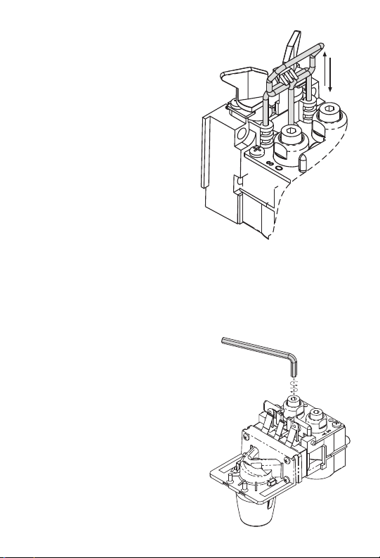
Remove the valv e cove r
and align the valve stems
with the mounting block.
Engage the valve and
depress the latch pin. Do
not force the latch pin
down or you may bend
the latch pin. If you are
having difficulty , simply
re-engage the valve and
try again. Be sure the
valve base is completely
seated against the mounting block. Open the shutoff valves by turning 1/4
turn (arrows pointed
toward the service line) to
engage system pressure.
FLOW CONTROL & BRIX
T wo simple adjustments are all you need to brix the
Flomatic valves. You will need a Flomatic S tube syrup
separator, 5/32 inch hex wrench, w atch and brix cup .
Place the S-tube syrup separator over the syrup diffuser and you are ready to
begin. You need not
remove the nozzle. Clockwise movement of the brix
nut adjustment screw
increases the flow rate and
vice versa. Restri ct the flow
by withdrawing the brix nut
adjustment screw as far as
it will go (turn counterclock wise). At this point the flow
will be at a minimum.
The 424 or 324 ceramic
flow controls can be
adjusted from 1.5 oz. /sec.
to 3.0 oz. /sec. T urn the
2 Part Number 5027981 8/10
Page 3

soda brix nut adjustment screw five full turns clockwise and the flow rate should be close to 2.5 oz/sec.
You will need to fine tune from there. F or fast flow ,
continue adjusting the valv e until you get 7.5 oz. of
soda in 3 seconds. Once the soda flow rate is set, then
establish the syrup ratio in exactly the sam e way.
The 464GP ceramic flow controls can be adjusted from
2.0 oz./sec. to 4.0 oz./sec. Turn the soda brix nut
adjustment screw five full turns clockwise and the flow
rate should be close to 3.0 oz./sec. You will need to
fine tune from there. For fast flow, continue adjust ing
the valve until you get 9.0 oz. Of soda in 3 seconds.
Once the soda flow rate is set, then establish the sy rup
ratio in exactly the same wa y.
Most brix cups are calibrated for a sta ndard brix r atio.
Adjust the syrup flow with movement of the adjusting
screw until the desired ratio is established. Some Flomatic valves are equipped with a flow washer on the
water side instead of flow controls. In that case, it is
not necessary to set the flow rate. Simply se t the
syrup ratio and you are done.
Flomatic juice valves may combine with a flow washer
on the water side. The syrup side may be manufactured
with a flow control or metering screw. The metering
screw turns clockwise to close and counter clockwise to
open. The screw does not have a stop; be sure not
to withdraw completely when under pressure.
SYNCHRONIZATION
When converting a manual 424 valve to electric solenoid operation, the actuators need to be removed prior
to installing the yoked armature soleno id coil. The
actuators are the white pivots that engage the pallet
stem.
Synchronization should only be nece ssary when converting an electric to manual v alv e, in which case y ou
may be adding the actuators. The soda a djustment
screw needs to be adjusted until it is snug (not tight ).
If too tight, the valve will remain open and leak. Set
Part Number 5027981 8/10 3
Page 4

the soda side first and then follow with the syrup actuator. The syrup actuator needs to be tightened until
snug and then backed off 1/4 turn. These settings will
allow for proper synchronization of the soda an d syrup
on a manual valve.
WATER / SODA ONLY
Installation of a Flomatic Add-A-Lever is easy. If you
have the pallet actuators as described above, simply
remove the valve cover and place the Add- A- Lever
(with the side attachment removed) on the end of the
pivot pin. Replace the cover and it will be firmly held in
place to provide soda only when desired. If y ou hav e
the electric operated val ve without the ac tuators, the
side attachment of the Add-A -Lever i s placed thro ugh
the pivot pin to push against the pallet stem.The lever
portion of the Add-A-Lever is placed on the end of the
pivot pin. Replace the valve cov er and the Add-A-Lever
will be held in place.
PORTION CONTROL
The Flomatic portion control electronics are contained
with the cover and can be factory or field instal led.
When installing in the field, simply order the portion
control conversion kit to upgrade an electric valve to
full portion control.
The portion control module is designed to simpl ify
installation for the service technician. No more wasted
product trying to set the time though tr ial and error.
The board can be programmed with the first pour.
The “Stop/Fill” button does just that; it serves as a
top-off button and cancels any of the timed portions if
the operator needs to abort th e pour. If the board has
never been programmed, the only button that will be
responsive is the “Stop/Fill” button. Cup siz es are preprogrammed at the factory: 1 sec. = small, 2 sec.=
medium, 3 sec. = large, 4 sec. = extra large. These
timed portions are helpful in setting flow rate; i.e., 7 ½
oz. soda in 3 seconds.
4 Part Number 5027981 8/10
Page 5

There are four cup sizes:
424/324 Portion Contr ol
T ouch Pad
464 Portion Control
T ouch P ad
small, medium, large and
Hidden Switch
extra large. Each cup size
needs to be programmed
separately . Set the flow
rate first and then brix the
STOP
FILL
valve. By doing so, yo u will
be sure to set times that
match your desired flow
rate. Once the v alve is
brixed, you can replace the
valve cover because the
times (cup sizes) are all set
from the front switch pad.
The switch pad has a hidden “program” switch
which needs to be held
down to keep the module in program mode.
Setting the times or programming is a two
handed operation: push
and hold the program
STOP
FILL
Hidden Switch
switch with one finger
while dispensing the cup
size you wish to program
with another. Once the drink is full, simply release the
cup size button to end the pour cy cle and then let go of
the program switch. Repeat the process for each cup
size and you are finished.
The module will remember one top-off cy cle automa tically if the foam height requires a top-off to complete
the pour. To program a top-off cycle, simply begin programming as described above. Once the foam crests
the top of the cup, PAUSE by removing your finger
from the cup size button. Do not release the progr am
button or it will think you’re done. Pause lo ng enough
for the foam to settle, and then continue your pour
with your finger on the same cup size button until the
Part Number 5027981 8/10 5
Page 6

cup is full. The portion control module will remember
the sequence “pour – pause – pour” just as it was executed. If you program the top-off feature, be sure to
train the operators so they do not pull a drink before
the cycle is complete. The portion control modu le will
finish the pour whether a cup is there or not.
AUTOMATIC FILL VALVE
The Flomatic Automatic Fill valv e can be used to dispense both carbonated and noncarbonated products.
The valve is factory set for carbonated products where
a delayed top-off is standard, and the wire-lead plug
should be attached to pins 1 and 2 (those furthest to
the left). If your installation uses noncarbonated products requiring no top-off, yo u will need to adjust the
position of the lever wire-lead plug on the electro nics.
For noncarbonated products, the wire-lead plug should
be attached to pins 2 and 3 (those furthest to the
right), as shown in the photo. The Auto matic Fill v alve
requires no sensitivity adjustments. The valve automatically delays top-off if more foam is present after
the initial pour, and performs a top-off more quickly if
less foam is present.
CLEANING
Under normal operating conditions, periodic cleaning is
minimal but necessary. Remove the nozzle and so da
diffuser . Using w arm water and a mild detergent, clean
each part with a brush. Once finished, rinse well an d
reassemble. If you wish to soak the no zzle and diffusers, soak them only is soda water, never use bleach.
Brush lever slot with w arm wat er to prev ent syrup
build-up and sticking. Wipe cover and panel with a
clean cloth and you are finished. Nothing more need
be done unless you experienced a problem. Regular
servicing and cleaning of the complete beverage system is advised to maintain proper functioning of the
equipment. Be sure to follow instructions provid ed by
the manufacturer .
6 Part Number 5027981 8/10
Page 7

TROUBLE SHOOTING
Occasionally, the v alve will not perform as desired.
Here are some helpful hints:
BRIX: Reset the flow rate and r e-brix the valve.
Look for foreign matter in the adjustment
screws, flow controls or pallet seats.
Sometimes if a system is not flushed
completely at startup, foreign particles,
etc. will be introduced into the system.
BUZZING: Make sure the plungers in the older style
double coil solenoid are properly aligned.
Do not lubricate the plungers with anything other than a “dry” product, e.g. , silicone spray.
LEAKS: Check for damaged or improperly fitted
O-rings. The slightest piece of hair, dust,
etc., on the sealing surface may contri bute to a leak. When in doubt, replace an
O-ring. Be sure you have the correct Oring and fitting combination for the
respective mounting block.
Part Number 5027981 8/10 7
Page 8

Manitowoc Beverage Systems
Manitowoc Beverage Systems
guarantees all Flomatic products free from
defects in material and workmanship under
normal use and service for two years from
date of purchase. If defective, Manitowoc
Beverage Systems will, at its sole
discretion, repair or replace the defective
item at no charge.
FLOMATIC WARRANTY
2100 Future Drive
Sellersburg, IN 47172-1868 USA
TOLL -F REE: (800) 367-4233
TEL: (812) 246-7000 FAX: (812) 24 6-9922
Visit us online at: www.ma nitowocfsg.com
© 2010 Manitowoc
Continuing product improvements may neces-
sitate change of specifications without notice.
Part Number 5027981 8/10
 Loading...