

Page 1
Instructions
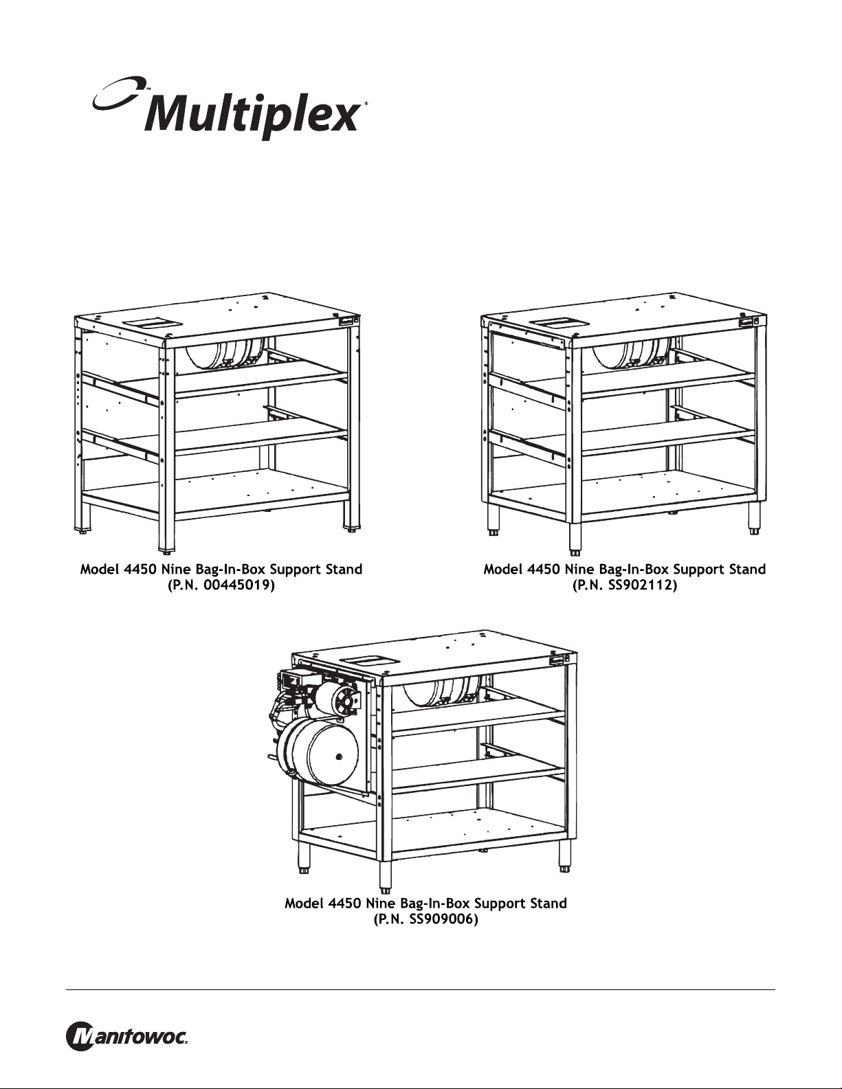
Subject: Model 4450 Nine Bag-In-Box Support St and with C02
Controls and Accumulator T ank
P.N. 00445019, P.N. 55902112, and P.N. 55909006
EI445019
8/09
Manitowoc Foodservice Sellersburg, 2100 Future Drive, Sellersburg, IN 47172, Tel: 812-246-7000, www.manitowocbeverage.com
Page 2
Model 4450 Nine Bag-In-Box Support Stand with C02 Controls and Accumulator Tank EI445019
!
Caution
!
Warning
To Avoid Serious Injury Read the following warnings before
beginning an installation. Falure to do so may result in possible
death or serious injury.
DO Adhere to all National and Local Plumbing and Electrical Safety Codes.
DO Turn “Off” incoming electrical service switches when servicing, installing, or repairing equipment.
DO Check that all flare fittings on the carbonation tank(s) are tight. This check should be performed with a
wrench to ensure a quality seal.
DO Inspect pressure on Regulators before starting up equipment.
DO Protect eyes when working around refrigerants.
DO Use caution when handling metal surface edges of all equipment.
DO Handle C0
DO Store C0
2 cylinders and gauges with care. Secure cylinders properly against abrasion.
2 cylinder(s) in well ventilated areas.
DO NOT Throw or drop a C0
DO NOT Connect the C0
possible death or injury . Best to connect th e C0
DO NOT Store C0
DO NOT Release C0
2 cylinders in temperature above 125˚ F (51. 7˚ C) near furnace s, radiator or sources of heat.
2 gas from old cylinder.
DO NOT Touch Refrigeration lines inside units, some may exceed temperatures of 200
2 cylinder. Secure the cylinder(s) in an upright position with a chain.
2 cylinder(s) directly to the product container . Doing so will result in an explosion causing
2 cylinder(s) to a regulator(s).
˚ F (93.3˚ C).
NOTE: Water pipe connections and fixtures directly connected to a potable water supply sha ll be sized, installed and
maintained in accordance with Federal, State, and Local codes.
DANGER OF ELECTRICAL SHOCK - Disconnect and lock out all
electrical power sources before performing service or maintenance on
this machine -- except when electrical tests are being performed by
qualified service personnel.
Manitowoc Foodservice Sellersburg, 2100 Future Drive, Sellersburg, IN 47172, Tel: 812-246-7000, www.manitowocbeverage.com
Page 3

Model 4450 Nine Bag-In-Box Support Stand with C02 Controls and Accumulator Tank EI445019
INITIAL SET-UP
1. Assemble the Syrup Pumps to rear mounting plate (refer to figure 1).
2. Place stand in desired location. Adjust feet of stand to level and stabilize.
3. Place the Refrigeration Unit on stand. Align holes to secure unit to stand with two (2) 5/ 8" screws.
NOTE: The mounting hole patterns are located so all Refrigeration Units mount flush with the front surface of the
stand.
4. Install the Bag-in-Box shelves (refer to figure 2).
INSTALLATION OF THE WATER FILTER SYSTEM (REFER TO FIGURE 3)
1. Assemble The Filter System to right side of stand.
2. Align holes in horizontal center cross member with holes in the st and. Fasten with 1/4 Hex head screws and nut s.
Manitowoc Foodservice Sellersburg, 2100 Future Drive, Sellersburg, IN 47172, Tel: 812-246-7000, www.manitowocbeverage.com
Page 4

Model 4450 Nine Bag-In-Box Support Stand with C02 Controls and Accumulator Tank EI445019
INSTALLATION OF THE WATER BOOSTER SYSTEM (REFER TO FIGURE 4)
1. Using 1/4" carriage bolts and nuts, assemble "J" shaped Booster Pump Mounting Bracket to lef t side of sta nd top.
2. Hang the Booster Pump on the "J" bracket.
3. Attach the bottom of the Wa ter Booste r Pump to th e shel f angle with 1 / 4" hex h ead screw and nut. Tighten each
nut and screw.
4. Remove and discard the jumper line connecting the Coarse Filter Outlet to the Fine Filter Inlet (refer to figure 5).
5. Locate the 16 ft coil of J / / 00 blue tubing packed with Refrigeration Unit. Cut into two (2) 8 ft pieces. Assemble a
1 h" Barb-stem adaptor and swivel nut to one (1) en d of bot h tub e s. Use two (2 ) tab-clam ps per connection.
6. Attach one (1) line to the fitting labeled "#27 Inlet" on the Water Booster Pump. Tag the opposite end of the line
"#27" with the tag provided.
7. Attach the other 8 ft line to the fitting on the Water Booster marked "#28 Outlet". Tag the opposite end with the
"#28" tag provided.
8. Route lines behind Refrigeration Unit to the Filter Sysem.
9. Attach the line labeled "#27" to the Outlet of the Coarse Filter using a 3// compression nut furnished with the unit.
10. Attach the line labeled "#28" in the same fashion to the 4 Inlet of the Fine Filter.
TESTING THE WATER BOOSTER SYSTEM
NOTE: Note: Install the Water Booster System only after Refrig eration Unit installation is complete.
1. Turn "on" main wate r supply. Check all connections for leaks.
2. Plug the Booster Pump power cord into receptacle. The Booster Pump will not run until the Low Water Pressure Circuit
times out (approximately 3 minutes). When the Booster Pump r uns and cycles "off", the boo sted water pressure sh ould
indicate 85 psi (2.9 bar).
3. Bleed off water until pressure falls to approximately 65 psi (2.2 bar). Pump should cycle "on" again and "of f" when the
pressure reaches 85 psi (2.9 bar). To make adjustments, refer to instructions inside the Pressure Switch cover.
Manitowoc Foodservice Sellersburg, 2100 Future Drive, Sellersburg, IN 47172, Tel: 812-246-7000, www.manitowocbeverage.com
 Loading...