

Page 1
Beermaster
Refrigeration Unit
with Electronic Refrigeration Control
Installation, Use & Care Manual
This manual is updated as new information and models are released.
Visit our website for the latest manual. www.manitowocfsg.com
America’s Quality Choice in Refrigeration
Part Number 000003914 1/11
Page 2
Safety Notices
!
Warning
!
Caution
Important
!
Caution
Important
!
Warning
As you work on Manitowoc equipment, be sure to pay
close attention to the safety notices in this manual.
Disregarding the notices may lead to serious injury and/
or damage to the equipment.
Throughout this manual, you will see the following types
of safety notices:
Text in a Warning box alerts you to a potential
personal injury situation. Be sure to read the
Warning statement before proceeding, and work
carefully.
Text in a Caution box alerts you to a situation in
which you could damage the equip ment. Be sure to
read the Caution statement before proceeding, and
work carefully.
Procedural Notices
As you work on Manitowoc equipment, be sure to read
the procedural notices in this manual. These notices
supply helpful information which may assist you as you
work.
Throughout this manual, you will see the following types
of procedural notices:
Read These Before Proceeding:
Proper installation, care and maintenance are
essential for maximum performance and trouble-free
operation of your Manitowoc equipment. Read and
understand this manual. It contains valuable care
and maintenance information. If you encounter
problems not covered by this manual, do not
proceed, contact Manitowoc Foodservice Group.
We will be happy to provide assistance.
Routine adjustments and maintenance procedures
outlined in this manual are not covered by the
warranty.
PERSONAL INJURY POTENTIAL
Do not operate equipment that has been misused,
abused, neglected, damaged, or altered/modified
from that of original manufactured specifications.
NOTE: SAVE THESE INSTRUCTIONS.
Text in an Important box provides you with
information that may help you perform a procedure
more efficiently. Disregarding this information will not
cause damage or injury, but it may slow you down as
you work.
NOTE: Text set off as a Note provides you with simple,
but useful, extra information about th e pr oce dur e yo u
are performing.
We reserve the right to make product improvements at any time.
Specifications and design are subject to change without notice.
Page 3

Section 1
General Information
Section 2
Installation
Table of Contents
Read This Manual. . . . . . . . . . . . . . . . . . . . . . . . . . . . . . . . . . . . . . . . . . . . . . . . . 1-1
Unit Inspection . . . . . . . . . . . . . . . . . . . . . . . . . . . . . . . . . . . . . . . . . . . . . . . . . . . 1-1
Model Numbers. . . . . . . . . . . . . . . . . . . . . . . . . . . . . . . . . . . . . . . . . . . . . . . . . . . 1-1
How to Read a Model Number. . . . . . . . . . . . . . . . . . . . . . . . . . . . . . . . . . . . . . . 1-1
Accessories. . . . . . . . . . . . . . . . . . . . . . . . . . . . . . . . . . . . . . . . . . . . . . . . . . . . . . 1-1
Special Applications. . . . . . . . . . . . . . . . . . . . . . . . . . . . . . . . . . . . . . . . . . . . . . . 1-1
Attention: Marine Installations . . . . . . . . . . . . . . . . . . . . . . . . . . . . . . . . . . . 1-1
Outdoor Applications . . . . . . . . . . . . . . . . . . . . . . . . . . . . . . . . . . . . . . . . . . 1-1
Specifications . . . . . . . . . . . . . . . . . . . . . . . . . . . . . . . . . . . . . . . . . . . . . . . . . . . . 1-1
Serial Plate Location . . . . . . . . . . . . . . . . . . . . . . . . . . . . . . . . . . . . . . . . . . . . . . 1-2
Warranty Information . . . . . . . . . . . . . . . . . . . . . . . . . . . . . . . . . . . . . . . . . . . . . . 1-2
General . . . . . . . . . . . . . . . . . . . . . . . . . . . . . . . . . . . . . . . . . . . . . . . . . . . . . . . . . 2-1
Dimensions and Clearances — All Models . . . . . . . . . . . . . . . . . . . . . . . . . . . . 2-1
Remote Condenser . . . . . . . . . . . . . . . . . . . . . . . . . . . . . . . . . . . . . . . . . . . 2-2
Safe Installation Dos and Don’ts. . . . . . . . . . . . . . . . . . . . . . . . . . . . . . . . . . . . . 2-2
Location Requirements . . . . . . . . . . . . . . . . . . . . . . . . . . . . . . . . . . . . . . . . . . . . 2-3
Multiplex Chiller Model Selection Chart . . . . . . . . . . . . . . . . . . . . . . . . . . . 2-3
Clearances . . . . . . . . . . . . . . . . . . . . . . . . . . . . . . . . . . . . . . . . . . . . . . . . . 2-3
Ratings . . . . . . . . . . . . . . . . . . . . . . . . . . . . . . . . . . . . . . . . . . . . . . . . . . . . 2-3
Kitchen Equipment Installer Representative Responsibilities . . . . . . . . . . . 2-3
Requirements for Refrigeration Units . . . . . . . . . . . . . . . . . . . . . . . . . . . . . 2-3
Installer Instructions . . . . . . . . . . . . . . . . . . . . . . . . . . . . . . . . . . . . . . . . . . . . . . 2-4
Preparation . . . . . . . . . . . . . . . . . . . . . . . . . . . . . . . . . . . . . . . . . . . . . . . . . 2-4
Electrical . . . . . . . . . . . . . . . . . . . . . . . . . . . . . . . . . . . . . . . . . . . . . . . . . . . . . . . . 2-4
General . . . . . . . . . . . . . . . . . . . . . . . . . . . . . . . . . . . . . . . . . . . . . . . . . . . . 2-4
Minimum Circuit Ampacity . . . . . . . . . . . . . . . . . . . . . . . . . . . . . . . . . . . . . 2-4
Electrical Requirements . . . . . . . . . . . . . . . . . . . . . . . . . . . . . . . . . . . . . . . 2-4
Specifications . . . . . . . . . . . . . . . . . . . . . . . . . . . . . . . . . . . . . . . . . . . . . . . 2-4
Grounding Instructions . . . . . . . . . . . . . . . . . . . . . . . . . . . . . . . . . . . . . . . . 2-5
Part Number 000003914 1/11 i
Page 4

Table of Contents (continued)
Conduit. . . . . . . . . . . . . . . . . . . . . . . . . . . . . . . . . . . . . . . . . . . . . . . . . . . . . . . . . . 2-6
Introduction . . . . . . . . . . . . . . . . . . . . . . . . . . . . . . . . . . . . . . . . . . . . . . . . . 2-6
Floor Chases . . . . . . . . . . . . . . . . . . . . . . . . . . . . . . . . . . . . . . . . . . . . . . . . 2-6
Overhead Installation . . . . . . . . . . . . . . . . . . . . . . . . . . . . . . . . . . . . . . . . . . 2-8
Basement Construction . . . . . . . . . . . . . . . . . . . . . . . . . . . . . . . . . . . . . . . . 2-9
Connecting Beer Conduit . . . . . . . . . . . . . . . . . . . . . . . . . . . . . . . . . . . . . . 2-10
Conduit Kit . . . . . . . . . . . . . . . . . . . . . . . . . . . . . . . . . . . . . . . . . . . . . . . . . . 2-11
Installing the Conduit Kit . . . . . . . . . . . . . . . . . . . . . . . . . . . . . . . . . . . . . . . 2-13
Beer Restrictor Lines . . . . . . . . . . . . . . . . . . . . . . . . . . . . . . . . . . . . . . . . . . 2-14
Balancing the System. . . . . . . . . . . . . . . . . . . . . . . . . . . . . . . . . . . . . . . . . . . . . . 2-15
Determining Restrictor Line Length and Applied Keg Pressure . . . . . . . . . 2-15
Starting Up the System . . . . . . . . . . . . . . . . . . . . . . . . . . . . . . . . . . . . . . . . 2-15
Beermaster Wine Dispensing Kit. . . . . . . . . . . . . . . . . . . . . . . . . . . . . . . . . . . . . 2-16
Introduction . . . . . . . . . . . . . . . . . . . . . . . . . . . . . . . . . . . . . . . . . . . . . . . . . 2-16
Installing . . . . . . . . . . . . . . . . . . . . . . . . . . . . . . . . . . . . . . . . . . . . . . . . . . . 2-16
Positioning of Refrigeration Unit . . . . . . . . . . . . . . . . . . . . . . . . . . . . . . . . . 2-17
Equipment Placement . . . . . . . . . . . . . . . . . . . . . . . . . . . . . . . . . . . . . . . . . 2-17
Electrical Connections . . . . . . . . . . . . . . . . . . . . . . . . . . . . . . . . . . . . . . . . . 2-17
Insulating Connections . . . . . . . . . . . . . . . . . . . . . . . . . . . . . . . . . . . . . . . . 2-19
Aeroquip Connection . . . . . . . . . . . . . . . . . . . . . . . . . . . . . . . . . . . . . . . . . . . . . . 2-19
Condenser and Pre-charged Lines Installation . . . . . . . . . . . . . . . . . . . . . . . . . 2-19
Multiplex Remote Condenser Pre-installation Requirements . . . . . . . . . . . 2-19
Multiplex Pre-charged Refrigeration Lines Pre-installation Requirements . 2-20
Installing the Multiplex Remote Condenser . . . . . . . . . . . . . . . . . . . . . . . . . 2-20
Connecting the Pre-charged Refrigeration Lines . . . . . . . . . . . . . . . . . . . . 2-21
Preparing Glycol . . . . . . . . . . . . . . . . . . . . . . . . . . . . . . . . . . . . . . . . . . . . . . . . . . 2-22
Mixing Glycol Solution . . . . . . . . . . . . . . . . . . . . . . . . . . . . . . . . . . . . . . . . . 2-22
Additional Glycol Circulating Pump and Motor Kit . . . . . . . . . . . . . . . . . . . . . . 2-23
Installing the Glycol Circulating Pump and Motor Kit . . . . . . . . . . . . . . . . . . 2-23
Beermaster Dispensing Towers. . . . . . . . . . . . . . . . . . . . . . . . . . . . . . . . . . . . . . 2-25
Introduction . . . . . . . . . . . . . . . . . . . . . . . . . . . . . . . . . . . . . . . . . . . . . . . . . 2-25
Dispensing Tower Template for Beermaster Dispensing Tower . . . . . . . . . 2-25
Beermaster High Pressure CO
Introduction . . . . . . . . . . . . . . . . . . . . . . . . . . . . . . . . . . . . . . . . . . . . . . . . . 2-26
Kit Contents . . . . . . . . . . . . . . . . . . . . . . . . . . . . . . . . . . . . . . . . . . . . . . . . . 2-26
Installing . . . . . . . . . . . . . . . . . . . . . . . . . . . . . . . . . . . . . . . . . . . . . . . . . . . 2-26
Regulator (00211500) . . . . . . . . . . . . . . . . . . . 2-26
2
ii Part Number 000003914 1/11
Page 5

Section 3
Operation
Table of Contents (continued)
Beermaster Dual Secondary Regulator Kit (00211400) . . . . . . . . . . . . . . . . . . . 2-26
Introduction . . . . . . . . . . . . . . . . . . . . . . . . . . . . . . . . . . . . . . . . . . . . . . . . . 2-26
Kit Contents . . . . . . . . . . . . . . . . . . . . . . . . . . . . . . . . . . . . . . . . . . . . . . . . . 2-26
Installing . . . . . . . . . . . . . . . . . . . . . . . . . . . . . . . . . . . . . . . . . . . . . . . . . . . 2-26
Beermaster Blenders . . . . . . . . . . . . . . . . . . . . . . . . . . . . . . . . . . . . . . . . . . . . . . 2-28
N
/CO2 Blender (Single — 00520182, Dual — 00520183) . . . . . . . . . . . . . 2-28
2
Installation Checklist . . . . . . . . . . . . . . . . . . . . . . . . . . . . . . . . . . . . . . . . . . . . . . 2-29
Typical System . . . . . . . . . . . . . . . . . . . . . . . . . . . . . . . . . . . . . . . . . . . . . . . . . . . 3-1
How the Multiplex Works . . . . . . . . . . . . . . . . . . . . . . . . . . . . . . . . . . . . . . . . . . . 3-2
Start-up. . . . . . . . . . . . . . . . . . . . . . . . . . . . . . . . . . . . . . . . . . . . . . . . . . . . . . . . . . 3-2
Placing Equipment in Operation . . . . . . . . . . . . . . . . . . . . . . . . . . . . . . . . . 3-2
Sequence of Operation. . . . . . . . . . . . . . . . . . . . . . . . . . . . . . . . . . . . . . . . . . . . . 3-2
Electronic Control . . . . . . . . . . . . . . . . . . . . . . . . . . . . . . . . . . . . . . . . . . . . 3-2
Equipment Setup and Close Procedure . . . . . . . . . . . . . . . . . . . . . . . . . . . . . . . 3-5
Equipment Setup Procedure . . . . . . . . . . . . . . . . . . . . . . . . . . . . . . . . . . . . 3-5
Equipment Close Procedure . . . . . . . . . . . . . . . . . . . . . . . . . . . . . . . . . . . . 3-5
System Calculators. . . . . . . . . . . . . . . . . . . . . . . . . . . . . . . . . . . . . . . . . . . . . . . . 3-6
Beer Pump, System Pressure and Choker Calculator . . . . . . . . . . . . . . . . 3-6
Blended Gas Beer System Pressure and Choker Calculator . . . . . . . . . . . 3-7
Pure CO
Beer System Pressure and Choker Calculator . . . . . . . . . . . . . . 3-8
2
Section 4
Maintenance
Major Component s . . . . . . . . . . . . . . . . . . . . . . . . . . . . . . . . . . . . . . . . . . . . . . . . 4-1
Scheduled Frequency. . . . . . . . . . . . . . . . . . . . . . . . . . . . . . . . . . . . . . . . . . . . . . 4-1
Shipping, Storage and Relocation. . . . . . . . . . . . . . . . . . . . . . . . . . . . . . . . . . . . 4-2
Section 5
Before Calling for Service
Checklist . . . . . . . . . . . . . . . . . . . . . . . . . . . . . . . . . . . . . . . . . . . . . . . . . . . . . . . . 5-1
Error Notes. . . . . . . . . . . . . . . . . . . . . . . . . . . . . . . . . . . . . . . . . . . . . . . . . . . . . . . 5-3
Dispensing Stations . . . . . . . . . . . . . . . . . . . . . . . . . . . . . . . . . . . . . . . . . . . 4-1
Beverage Conduits . . . . . . . . . . . . . . . . . . . . . . . . . . . . . . . . . . . . . . . . . . . 4-1
Air Compressor . . . . . . . . . . . . . . . . . . . . . . . . . . . . . . . . . . . . . . . . . . . . . . 4-1
Refrigeration Unit . . . . . . . . . . . . . . . . . . . . . . . . . . . . . . . . . . . . . . . . . . . . . 4-1
Gas Blender . . . . . . . . . . . . . . . . . . . . . . . . . . . . . . . . . . . . . . . . . . . . . . . . . 4-1
CO
Gas Supply . . . . . . . . . . . . . . . . . . . . . . . . . . . . . . . . . . . . . . . . . . . . . 4-1
2
iii Part Number 000003914 1/11
Page 6

Table of Contents (continued)
THIS PAGE INTENTIONALLY LEFT BLANK
iv Part Number 000003914 1/11
Page 7
Section 1
!
Warning
!
Warning
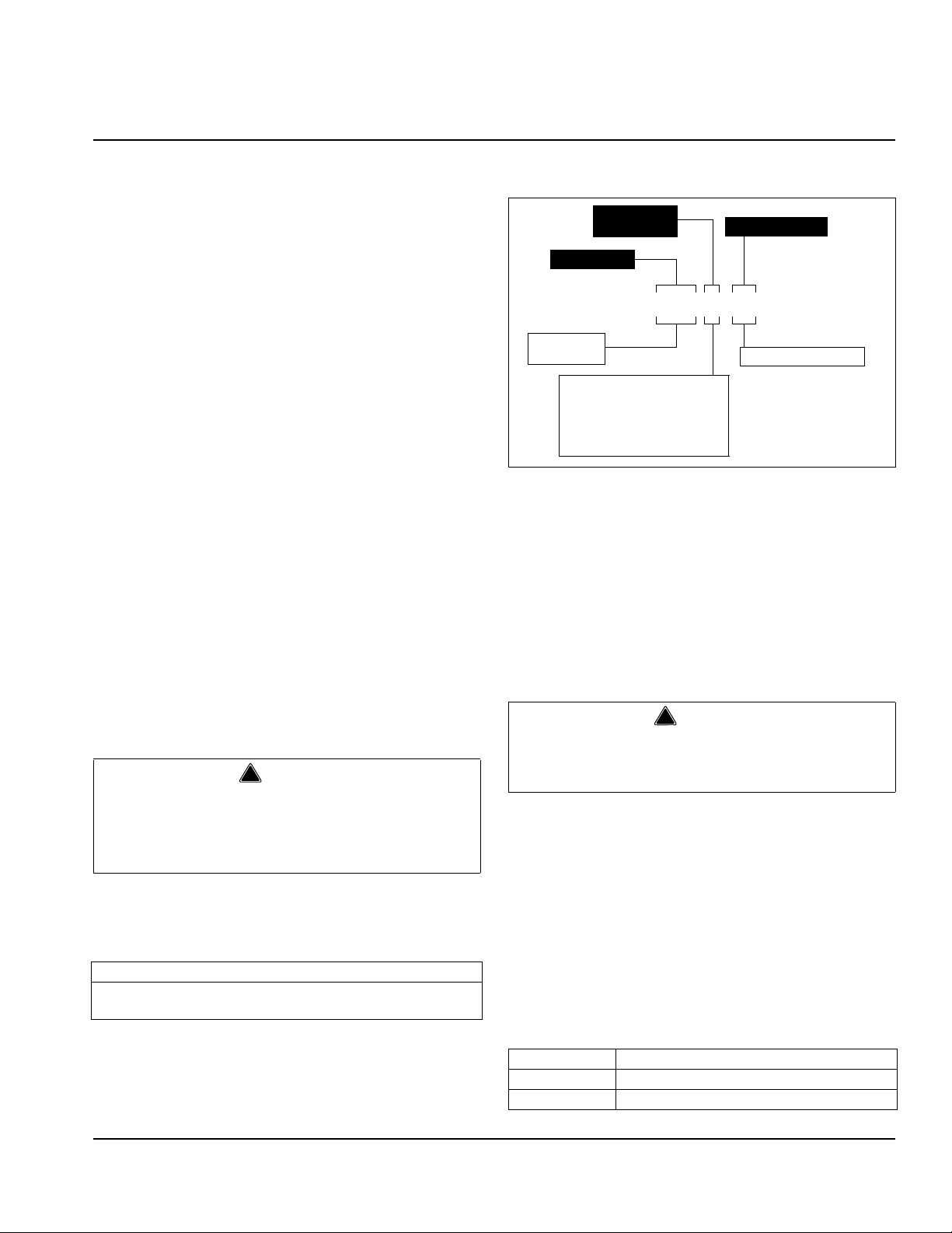
04 - R404a refrigerant
Model Prefix
Model Base
300 A 04
A - Air-cooled
AX - Air-cooled, international
R - Remote
RX - Remote, international
W - Water-cooled
WX - Water-cooled, international
Condenser
Type
300 - 1 hp
450 - 2.2 hp
General Information
Read This Manual
Manitowoc Food Service developed this manual as a
reference guide for the owner/operator and installer of
this equipment. Please read this manual before
installation or operation of the machine. A qualified
service technician must perform installation and start-up
of this equipment, consult Section 5 within this manual
for service assistance.
If you cannot correct the service problem, call your
Manitowoc Beverage Equipment (MBE) Service Agent
or Distributor. Always have your model and serial
number available when you call.
Your Service Agent ____________________________
Service Agent Telephone Number_________________
Your Local MBE Distributor ______________________
Distributor Telephone Number____________________
Model Number _______________________________
Serial Number ________________________________
Installation Date ______________________________
Unit Inspection
Thoroughly inspect the unit upon delivery. Immediately
report any damage that occurred during tr ansportation to
the delivery carrier. Request a written inspection report
from a claims inspector to document any necessary
claim.
PERSONAL INJURY POTENTIAL
Do not operate equipment that has been misused,
abused, neglected, damaged, or altered/modified
from that of original manufactured specifications.
Model Numbers
This manual covers the following models:
300A04, 300W04, 300R04, 300AX04, 300WX04, 300RX04,
450A04, 450W04, 450R04, 450AX04, 450WX04, 450RX04
Refrigeration Unit
How to Read a Model Number
Accessories
Depending on store type and location, various optional
equipment (such as CO
Panel, water filter kit, water
2
booster kit, etc.) may be added to this system. Install
and connect any optional equipment in the desired
location according to the installation instructions
provided with these kits/equipment.
Special Applications
ATTENTION: MARINE INSTALLATIONS
This unit is for use on vessels over 66 ft (20 m) in
length. This unit must not be installed in the engine
space of a gasoline-powered ship.
NOTE: This unit must be secured to the vessel during
installation. Models with part numbers beginn ing with the
letters TO are NOT marine listed.
OUTDOOR APPLICATIONS
TO Multiplex Beverage Recirculating units are ap proved
and listed by Underwriters Laboratories (UL). However
they are not UL approved for weather exposure
applications. These units must be installed in areas
where adequate protection from the elements is
provided, all other models are ETL listed.
Specifications
Part Number 000003914 1/11 1-1
Model Number of Flavors
300 Up to 22
450 Up to 32
Page 8
General Information Section 1
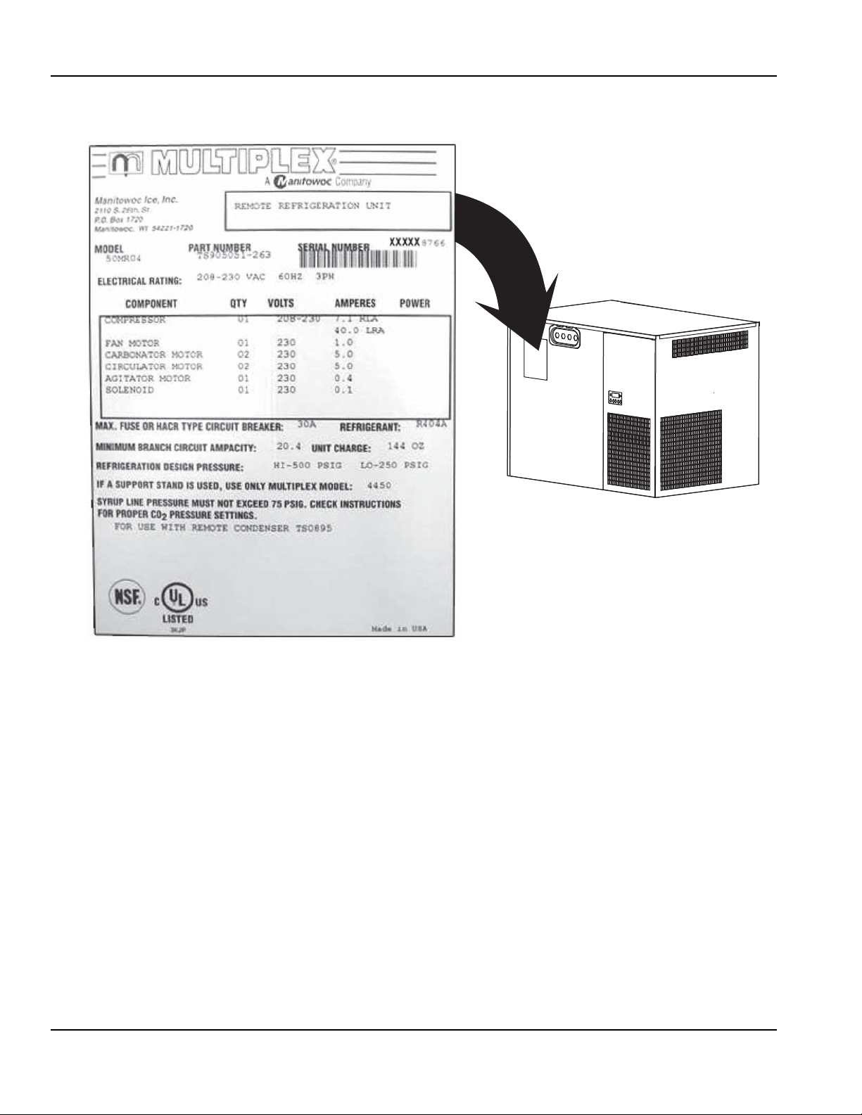
Serial Plate Location
Warranty Information
Consult your local MBE Distributor for terms and
conditions of your warranty. Your warranty specifically
excludes all beverage valve brixing, general
adjustments, cleaning, accessories and related
servicing.
Your warranty card must be returned to MBE to activate
the warranty on this equipment. If a warranty card is not
returned, the warranty period can begin when the
equipment leaves the MBE factory.
No equipment may be returned to MBE without a written
Return Materials Authorization (RMA). Equipment
returned without an RMA will be refused at MBE’s dock
and returned to the sender at the sender’s expense.
Please contact your local MBE distributor for return
procedures.
1-2
Part Number 000003914 1/11
Page 9
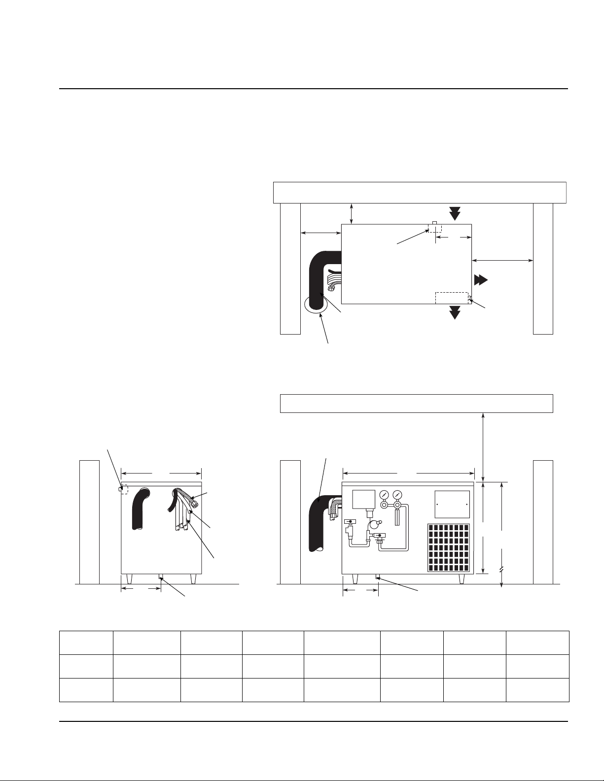
Section 2
Wall
6" (15.2 cm)
Diameter Chase minimum
3-7/8" (9.8 cm) Diameter
(4-7/8" [12.4 cm] Diameter
on Model 50)
Air Flow
Control
Switches
18"
(45.7 cm)
minimum
J
Electrical
Junction Box
6" (15.2 cm) minimum
12"
(30.5 cm)
minimum
Wall
Wall
Top View
Front ViewSide View
P
Wall
Electrical
Junction Box
Incoming Water
Line
Incoming CO
2
Supply Line
Incoming Syrup
Supply Lines
Drain Plug
W
Ceiling
Wall
18" (45.7 cm)
minimum
I
H
CO2 Regulator
Panel (Optional)
N
Drain Plug
Wall
Conduit to
Dispensing Towers
D
Installation
General
• Refrigeration units require stand or 6" (15.2 cm) legs. Refrigeration unit cannot be placed directly on floor.
• Conduit can be run through floor or ceiling chase.
Dimensions and Clearances — All Models
Model W D H
300 39-3/4"
450 42-1/4"
(101 cm)
(107.3 cm)
24-3/4"
(62.9 cm)
28-1/4"
(71.8 cm)
28-1/4"
(72.4 cm)
32-1/4"
(81.9 cm)
I
(with stand)
60-3/4"
(154.3 cm)
66-3/4"
(169.5 cm)
JNP
11"
(28 cm)
11"
(28 cm)
(15.2 cm)
(21.6 cm)
6"
8-1/2"
(30.5 cm)
(35.6 cm)
12"
14"
Part Number 000003914 1/11 2-1
Page 10
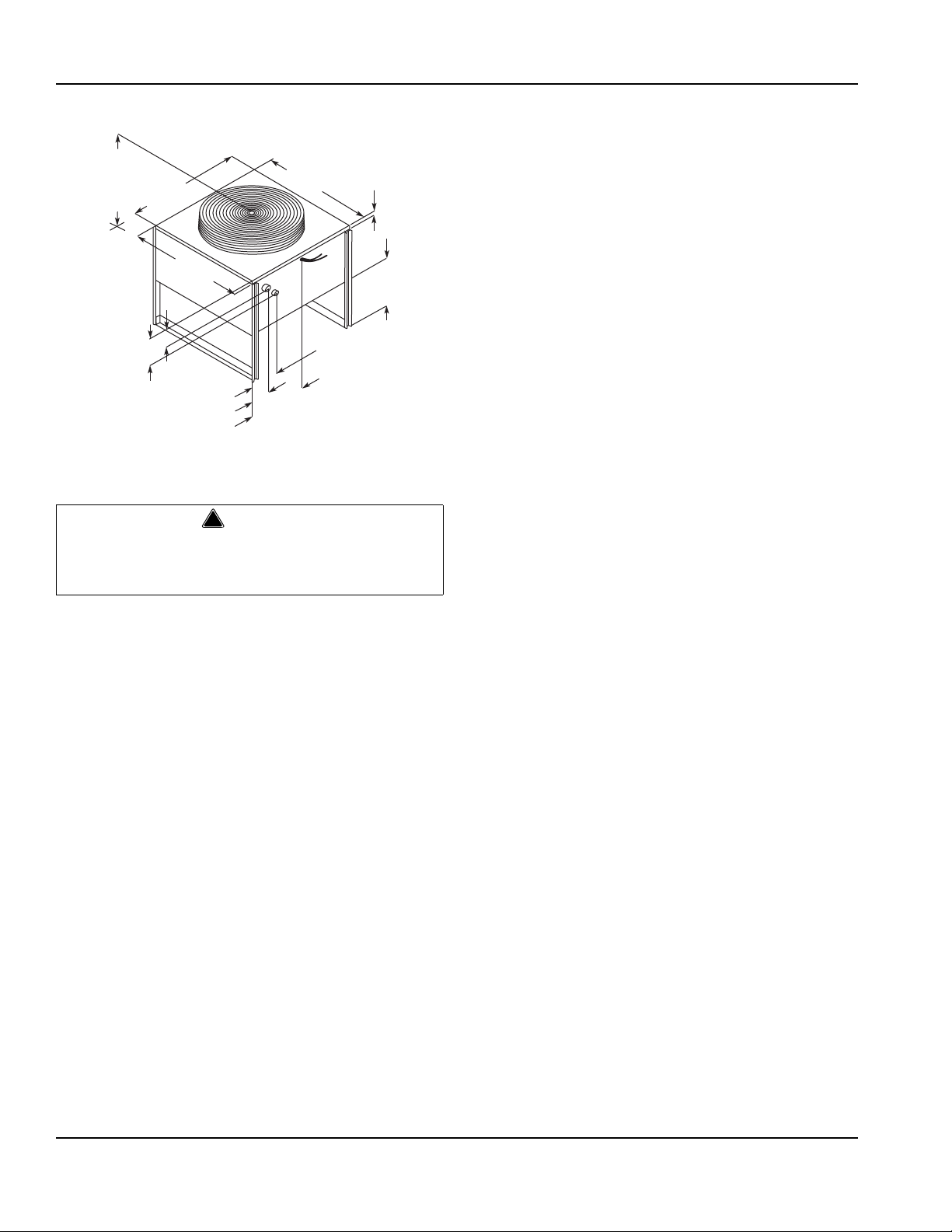
Installation Section 2
OPTIONAL
38.00" (96.52 cm)
34.00" (86.36 cm)
30.00" (76.20 cm)
29.50"
(74.93 cm)
29.16"
(74.06 cm)
6.00"
(15.24 cm)
3.50"
(8.89 cm)
4.00"
(10.16 cm)
14.62"
(37.13 cm)
6.50"
(16.51 cm)
OPTIONAL
20.00" (50.80 cm)
16.00" (40.64 cm)
12.00" (30.48 cm)
1.50"
(3.81 cm)
27.94"
(70.97 cm)
!
Warning
REMOTE CONDENSER
Safe Installation Dos and Don’ts
Read the following warnings before beginning an
installation. Failure to do so may result in possible
death or serious injury.
• DO adhere to all National and Local Plumbing and
Electrical Safety Codes.
• DO turn OFF incoming electrical service switches
when servicing, installing, or repairing equipment.
• DO check that all flare fittings are tight. This check
must be performed with a wrench to ensur e a quality
seal.
• DO inspect pressure on regulators before starting up
equipment.
• DO protect eyes when working around refrigerants.
• DO use caution when handling metal surface edges
of all equipment.
• DO handle CO
cylinders and gauges with care.
2
Secure cylinders properly against abrasion.
• DO store CO
cylinder(s) in well ventilated areas.
2
• DO NOT exhaust CO
gas (example: syrup pump)
2
into an enclosed area, including all types of walk-in
coolers, cellars, and closets.
• DO NOT throw or drop a CO
cylinder. Secure the
2
cylinder(s) in an upright position with a chain.
• DO NOT connect the CO
cylinder(s) directly to the
2
product container. Doing so will result in an explosion
causing possible death or injury. It is best to connect
the CO
• DO NOT store CO
cylinder(s) to a regulator(s).
2
cylinders in temperature above
2
125°F (51.7°C) near furnaces, radiator or sources of
heat.
• DO NOT release CO
gas from old cylinder.
2
• DO NOT touch refrigeration lines inside units; some
may exceed temperatures of 200°F (93.3°C).
NOTICE: All utility connections and fixtures must be
sized, installed, and maintained in accordance with
Federal, State, and Local codes.
2-2
Part Number 000003914 1/11
Page 11
Section 2 Installation
!
Warning
Location Requirements
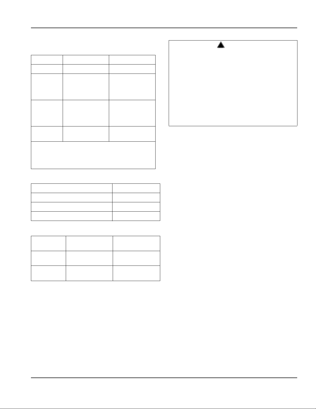
MULTIPLEX CHILLER MODEL SELECTION CHART
Model #* 300 450
Line length up to 300' up to 450'
Included
glycol
circulation
pump
Optional
glycol
circulation
pumps
Qty of
flavors**
* Chiller condensing options are available, refer to
Condenser and Pre-charged Lines Installation for details.
** Requires maximum number of optional pumps to reach
these levels.
up to 2 additional one additional
1 3
up to 22 up to 32
CLEARANCES
Control Side (Right) 18" (45.7 cm)
Connection Side (Left) 12" (30.5 cm)
Back Side 6" (15.2 cm)
Ceiling 18" (45.7 cm)
RATINGS
Model
300
450
Evaporator Rating
at 20°F (-6.5°C)
9,700 BTUH
2,340 kcal/hr
14,900 BTUH
3,310 kcal/hr
Heat Rejection
(Max.)
13,576 BTUH
3,685 kcal/hr
20,400 BTUH
4,285 kcal/hr
Select a location for the refrigeration unit that meets the
requirements of the building plans, local codes, and
personnel. The unit must be positioned for free airflow
as well as for future service. The following requirements
must be met:
• Beverage quality CO
gas (bulk or bottled supply)
2
with a minimum 3/8" (.96 cm) line
NOTE: Refer to serial plate on front of refrigeration unit
for voltage and amperage specifications. Make all
electrical connections at the junction box located at the
top rear of unit. Optional equipment may require
additional power supplies.
Carbon Dioxide (CO2) displaces oxygen. Exposure
to a high concentration of CO
gas causes tremors,
2
which are followed rapidly by loss of consciousness
and suffocation. If a CO
gas leak is suspected,
2
particularly in a small area, immediately ventilate the
area before repairing the leak. CO
lines and pumps
2
must not be installed in an enclosed space. An
enclosed space can be a cooler or small room or
closet. This may include convenience stores with
glass door self serve coolers. If you suspect CO
2
may build up in an area, venting o f the BIB pumps
and/or CO
monitors must be utilized.
2
KITCHEN EQUIPMENT INSTALLER REPRESENTATIVE RESPONSIBILITIES
Prior to scheduling Multiplex Equipment installer,
the following steps listed below must be completed:
1. Electrical power supply meeting the requirements for
the unit to be installed. (See the specification in this
section or refer to the unit’s serial plate).
2. CO
Gas (bulk or bottled supply); minimum 3/8" line.
2
3. A 120 VAC, 3-wire, 1 Phase, 60 Hz dual wall
receptacle for optional electrical equipm ent
(domestic only).
NOTE: Do not schedule the authorized Multiplex
Equipment Installer until all of the above have been
completed. It will only result in charge-backs to you for
the unnecessary trips.
REQUIREMENTS FOR REFRIGERATION UNITS
• Conduit can be run through floor or ceiling chase.
• 60°F (15.6°C) minimum and 105°F (40.5°C)
maximum operating ambient conditions.
• For indoor installation only.
• Beer supply can be located on stand or adjacent to
refrigeration unit.
Part Number 000003914 1/11 2-3
Page 12
Installation Section 2
Important
Important
!
Warning
Installer Instructions
The remainder of these instructions is to be
completed by an authorized Multiplex Installer.
These equipment instructions are intended to assist
qualified personnel in the unpacking, locating and the
initial operation of the Multiplex Beverage Equipment
Refrigeration Unit.
This publication must be saved for future reference.
Read instructions before attempting installation.
PREPARATION
The Multiplex Beverage Equipment Refrigeration Unit is
pre-assembled in the factory and requires minim u m
installation.
For future reference or to be used when ordering parts,
record the Model Number, Serial Number, Part Numbers
of Unit, Condenser (if remote), Towers, etc., an d Date of
Installation on the inside of this Manual. Leave manual
on site in a safe place. Do not discard manual.
Ambient Location Requirement
This equipment is rated for indoor use only. It will not
operate in sub-freezing temperature. In a situation when
temperatures drop below freezing, the equipment must
be turned off immediately and properly winterized.
Contact the manufacturer for winterization process.
Electrical
GENERAL
All wiring must conform to local, state and national
codes.
MINIMUM CIRCUIT AMPACITY
The minimum circuit ampacity is used to help select the
wire size of the electrical supply. (Minimum circuit
ampacity is not the beverage/ice machine’ s running amp
load.) The wire size (or gauge) is also dependent upon
location, materials used, length of run, etc., so it must be
determined by a qualified electrician.
ELECTRICAL REQUIREMENTS
Refer to Ice Machine Model/Serial Plate for
voltage/amperage specifications.
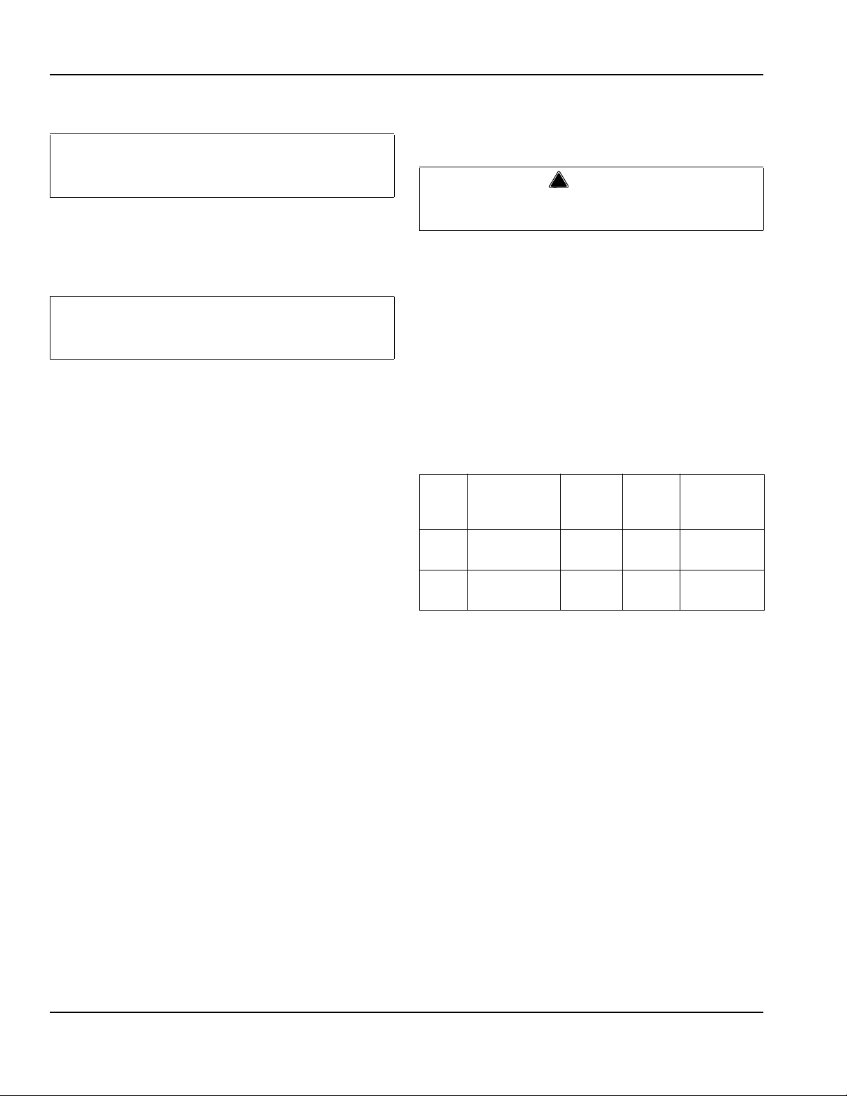
SPECIFICATIONS
Minimum
Circuit
Amps
20.6
20.6
25.2
11.6
Breaker Compressor
30A
25A
30A
20A
1 hp
1.9 kW
2.2 hp
2.0 kW
Model
300
450
Volt/Cycle/
Phase
208-230/60/1
230/50/1
208-230/60/3
230/400/50/3
2-4
Part Number 000003914 1/11
Page 13
Section 2 Installation
!
Warning
!
Warning
!
Warning
GROUNDING INSTRUCTIONS
When using electric appliances, basic precautions
The beverage/ice machine must be grounded in
accordance with national and local electrical codes.
This appliance must be grounded. In the event of
malfunction or breakdown, grounding provides a path of
least resistance for electric current to reduce the risk of
electric shock. This appliance is equipped with a cord
having an equipment-grounding conductor and a
grounding plug. The plug must be plugged into an
appropriate outlet that is properly inst alled and grounded
in accordance with all local codes and ordinances.
Improper connection of the equipment-grounding
conductor can result in a risk of electric shock. The
conductor with insulation having an outer surface
that is green with or without yellow stripes is the
equipment grounding conductor. If repair or
replacement of the cord or plug is necessary, do not
connect the equipment-grounding conductor to a
live terminal. Check with a qualified electrician or
serviceman if the grounding instructions are not
completely understood, or if in doubt as to whether
the appliance is properly grounded. Do not modify
the plug provided with the appliance — if it will not fit
the outlet, have a proper outlet installed by a
qualified electrician.
must always be followed, including the following:
a. Read all the instructions before using the
appliance.
b. To reduce the risk of injury, close supervision is
necessary when an appliance is used near
children.
c. Do not contact moving parts.
d. Only use attachments recommended or sold by
the manufacturer.
e. Do not use outdoors.
f. For a cord-connected appliance, the following
shall be included:
• Do not unplug by pulling on cord. To unplug,
grasp the plug, not the cord.
• Unplug from outlet when not in use and
before servicing or cleaning.
• Do not operate any appliance with a
damaged cord or plug, or after the appliance
malfunctions or is dropped or damaged in any
manner. Contact the nearest authorized
service facility for examination, repair, or
electrical or mechanical adjustment.
g. For a permanently connected appliance — Turn
the power switch to the off position when the
appliance is not in use and before servicing or
cleaning.
h. For an appliance with a replaceable lamp —
Always unplug before replacing the lamp.
Replace the bulb with the same type.
i. For a grounded appliance — Connect to a
properly grounded outlet only. See Grounding
Instructions.
Part Number 000003914 1/11 2-5
Page 14
Installation Section 2
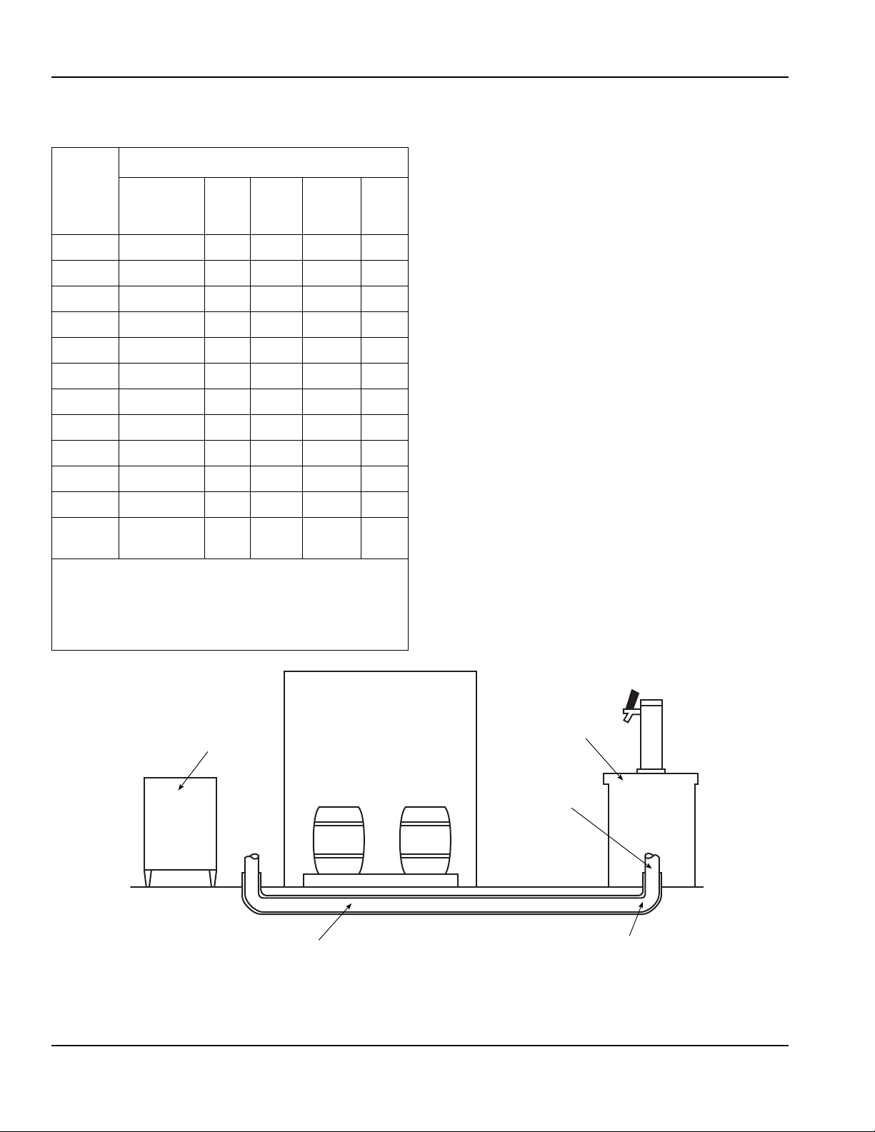
Beermaster™
Refrigeration Unit
Walk-in Cooler
Dispensing
Station
Beer Conduit
6" (15.2 cm) PVC
Conduit Chase
Wide Sweep Elbows
2 ft (61 cm) Radius
Conduit
CONDUIT SPECIFICATION CHART
Choose
# of Beer
Flavors
2 MC043346 2 2 1 4
3 MC053346 3 2 1 5
4 MC063346 4 2 1 6
5 MC073346 5 2 1 7
6* MC083346 6 2 1 8
6* MC103346 6 4 2 10
8 MC123346 8 4 2 12
10 MC143346 10 4 2 14
12 MC163346 12 4 2 16
15 MC193346 15 4 2 19
16 MC203346 16 4 2 20
Brewmaster
2 Conduit
Part #
Conduit Specifications
Beer
Lines
Glycol
Lines
Glycol
Circuits
Total
Lines
INTRODUCTION
The following instructions will provide information for
installing Multiplex Beer Conduit with your Beermaster
System. Areas which will be covered include routing the
conduit for different bar setups, connecting the conduit
at the Beermaster Glycol Chiller, connecting the conduit
at the beer cooler, and connecting the conduit at the
dispensing stations.
FLOOR CHASES
Before pulling beer conduit through a floor chase,
ensure the floor chase contains the following:
• 6" (15 cm) minimum PVC conduit chase
• Chase openings should extend 6" (15 cm) above
floor
• Wide sweep elbows (2 ft [0.6 m] radius)
• Chase must be clean and dry — no foreign materials
glycol
line**
* To maximize system performance on 6-flavor applications,
Multiplex recommends using a 10 line conduit with 4 glycol
lines/2 circuits.
** 2-line “glycol only” conduit, used between chiller and keg
cooler.
MC023346 2 1 2
2-6
Part Number 000003914 1/11
Page 15
Section 2 Installation
Pulling Conduit Through Floor Chase
1. Determine the most convenient way of routing
conduit, starting at the end which offers adequate
room for installation. The conduit installation process
requires the assistance of at least two (2) qualified
personnel.
2. Route the steel fish tape through chase opening.
Push fish tape through entire chase until it appears
at opposite end.
3. Locate an appropriate length of rope and tie to end
of fish tape (end which was routed through chase in
step 2). Approximately 2 ft (0.6 m) from steel fish
tape/rope connection, secure a swab to rope (use
mop heads or a bundle of rags for swab).
4. Pull end of fish tape from starting point through
chase with rope and swab. The swab will clean any
construction materials, moisture, or debris that may
exist in floor chase. Continue to swab the chase until
the swab exits the chase clean and dry.
5. After floor chase has been cleaned, remove steel
fish tape and swab from rope. Locate bundle of beer
conduit and unspool conduit to allow unrestricted
feed during installation process.
6. Locate rope through floor chase opening and
connect to proper end of beer conduit.
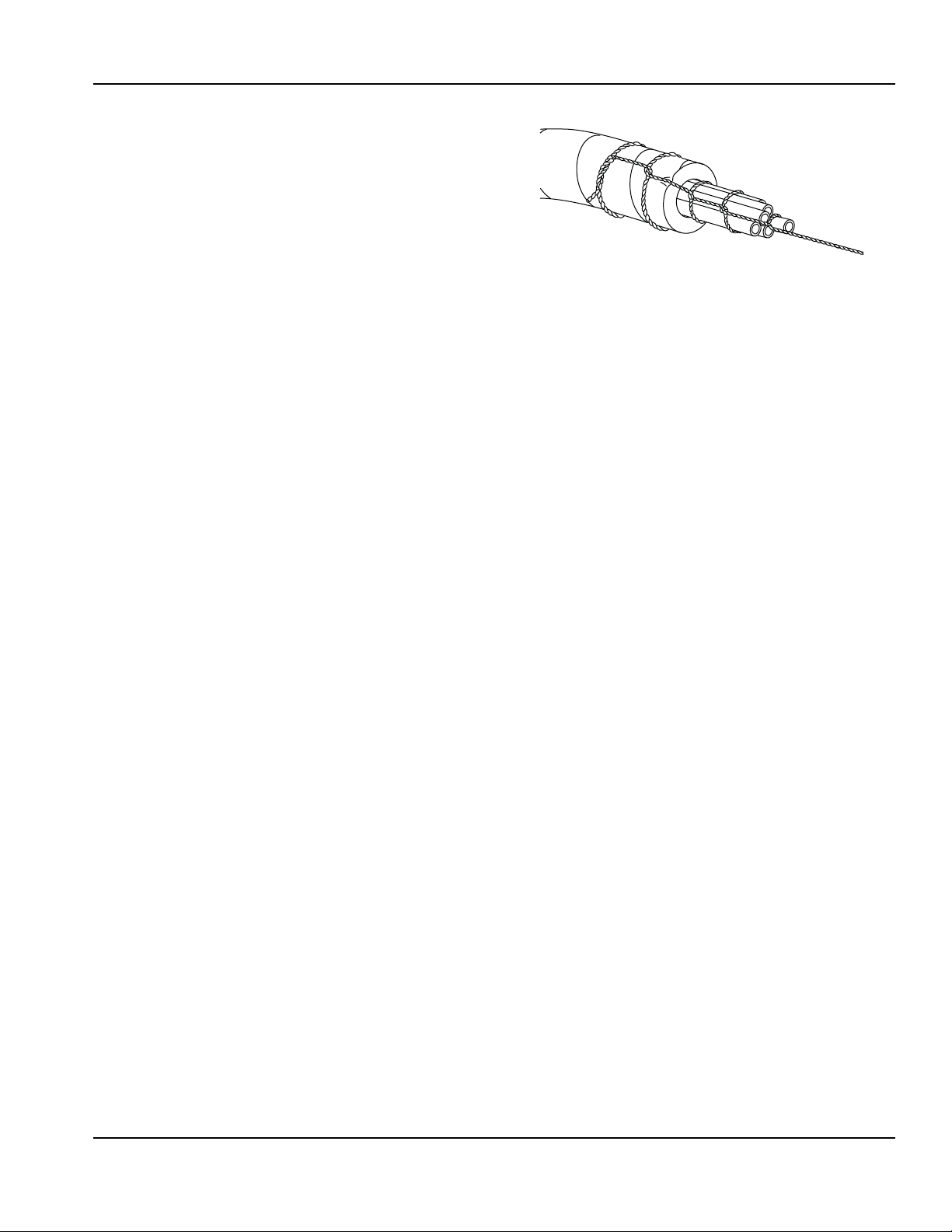
NOTE: The beer conduit is designed to be pulled
through floor chase in the direction of arrows printed on
conduit.
7. After rope has been connected, tap e end of cond uit,
including rope, and form conduit end to a point (se e
figure above). Tape will ensure that no contaminants
enter conduit tubes during installation.
8. Place pointed end of the conduit through chase
opening. While one person pushes the conduit
through chase, another person should be pulling the
conduit through the chase with rope at the opposite
end.
9. Once the conduit has been routed through the
chase, pull enough conduit through the openings to
ensure an adequate supply at each end of the chase
for connections.
Part Number 000003914 1/11 2-7
Page 16
Installation Section 2
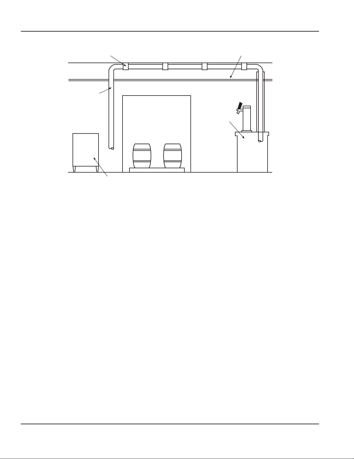
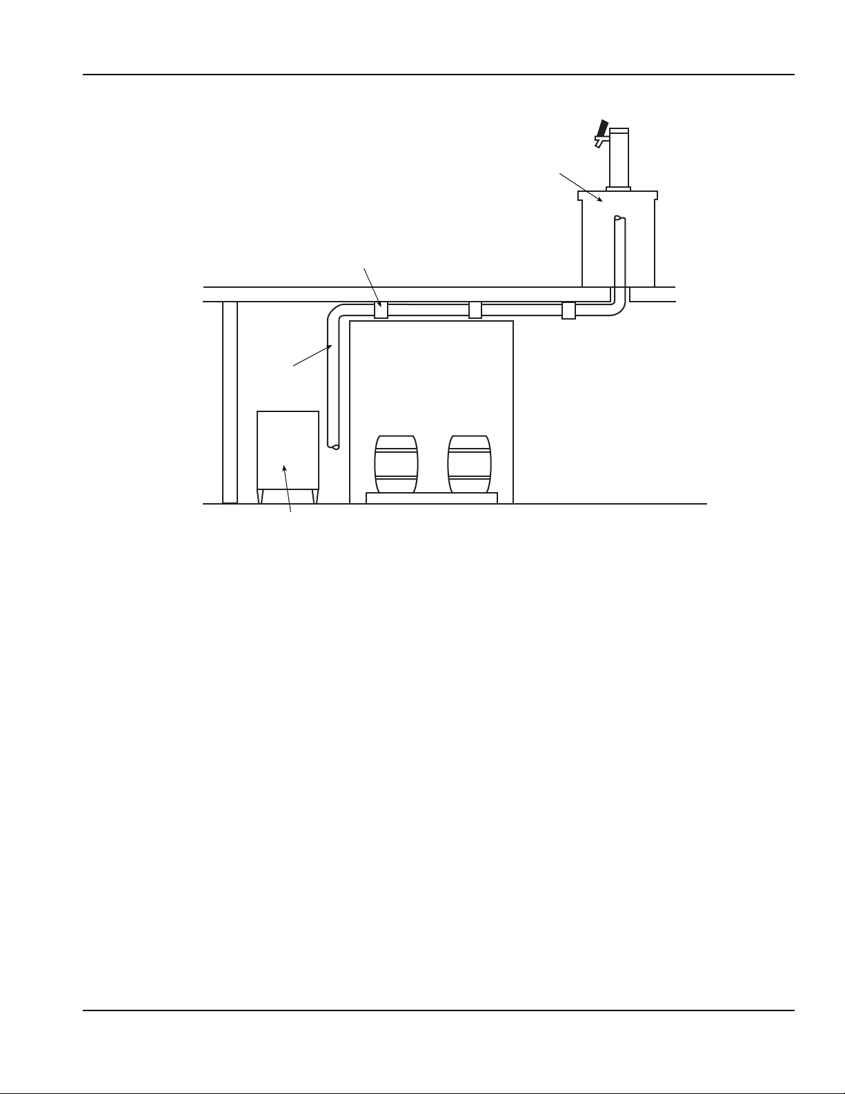
Beermaster™
Refrigeration Unit
Walk-in Cooler
Dispensing
Station
Ceiling Tiles
Conduit Hanger
Beer Conduit
OVERHEAD INSTALLATION
Refer to the figure above for the following:
1. Determine the correct location for routing the beer
conduit. Be sure to avoid heat ducts, hoods, gril ls, or
any sharp objects that may exist above drop ceiling
tile.
2. Unspool the beer conduit to allow unrestricted feed.
3. Route the conduit above ceiling tiles and connect to
ceiling and/or pipes using the appropriate conduit
hangers. Be sure the conduit is suspended above
ceiling tiles, not lying on the tiles. Care should be
taken when determining appropriate method of
handing conduit securely. Hanger s must no t cru s h
or pinch insulation. This will reduce cooling
efficiency.
4. Once the conduit has been routed, ensure an
adequate supply of conduit is provided at each end
to make all connections.
2-8
Part Number 000003914 1/11
Page 17
Section 2 Installation
Beermaster™
Refrigeration Unit
Walk-in Cooler
Dispensing
Station
Conduit Hanger
Beer
Conduit
BASEMENT CONSTRUCTION
Refer to the figure above for the following:
1. Unspool the beer conduit to allow unrestricted feed
during installation process.
2. Route the conduit up basement wall and secure with
appropriate conduit hangers.
3. After routing the conduit up the basement wall, route
conduit overhead on the basement ceiling. Connect
to the basement ceiling using appropriate conduit
hangers.
4. Once the conduit has been routed, ensure an
adequate supply of conduit is on hand to make all
connections.
Part Number 000003914 1/11 2-9
Page 18

Installation Section 2
!
Caution
Butterfly Cutter
Razor Knife
Beermaster™
Refrigeration Unit
Walk-in Cooler
Dispensing
Station
Main Beer
Conduit
Beer Conduit to
Walk-in Cooler
CONNECTING BEER CONDUIT
Before connecting the beer conduit at the walk-in beer
cooler and beer towers, ensure an adequate length of
conduit is being supplied to make proper connections.
Only an approved cutting tool should be used to cut
polyethylene tubing. The cutting tool should contain
a razor sharp cutting blade so that the tubing will not
be crushed when cutting. A razor blade knife or
butterfly tubing cutter is sufficient (see figures).
Multiplex packs a butterfly cutter with each
Beermaster Glycol Chiller.
1. Locate the lines of the beer conduit routed to the
Beermaster Glycol Chiller.
2. Using an approved cutting tool, cut the beer conduit
insulation along the top side while peeling insulation
back at the same time.
NOTE: Glycol circuit is a pair of lines; one blue and one
red. The blue line is the discharge or su pply line. The red
line is the return line.
3. Locate the return glycol supply lines of the beer
conduit and connect to the corresponding John
Guest fitting on the Beermaster Glycol Chiller.
4. Locate the discharge glycol supply lines of the beer
conduit and connect to the corresponding John
Guest fitting on the Beermaster Glycol Chiller.
5. Locate the glycol lines in the main conduit. Connect
the glycol lines of the beer unit to walk-in cooler
conduit to the glycol lines of the main beer conduit.
6. Locate the beer and glycol supply lines at the
dispensing station. Connect each beer line,
incoming glycol line, and outgoing glycol line to the
appropriate John Guest fitting at the dispensing
station.
NOTE: The 3/8" I.D. poly line used in the beer conduit is
thin wall tubing. Barbed fittings should not be used. The
usage of barbed fittings causes thin wall tubing to split or
crack and leaks will result.
2-10
Part Number 000003914 1/11
Page 19

Section 2 Installation
CONDUIT KIT
General
The following instructions will cover installation
procedures required for properly connecting each
component of the Beermaster system. These
instructions also contain the necessary info rmation
required for; calculating restrictor line length, required
regulator operating pressures and sta rt-up procedures. It
is recommended that before proceeding with these
instructions you ensure that each of the following items
have been properly installed. Items listed in suggested
order of installation:
1. Glycol Chiller Unit
2. Dispensing Towers
3. Secondary Regulator Kits
4. Beer Conduit
5. High Pressure CO
Regulator Kit
2
6. Blender Kit or Beer Pumps
7. Air Compressor Kit (optional)
8. Low CO
Alarm Kit
2
Once the above items have been installed, the following
instructions can be completed.
NOTE: Your system may not include each item.
Kit contents
Four (4) and Seven (7) line conduit kits
• Three (3) Return bends
• Eight (8) Elbows
• 29 Unions
• Five (5) Tail pieces
• Five (5) Beer nuts
• One (1) 60 ft of PVC tape
• One (1) 60 ft of foil
• One (1) Spanner wrench
10 and 14 line conduit kits
• Four (4) Return bends
• 15 Elbows
• 42 Unions
• Eight (8) Tail pieces
• Eight (8) Beer nuts
• One (1) 60 ft of PVC tape
• One (1) 60 ft of foil
• One (1) Spanner wrench
Part Number 000003914 1/11 2-11
Page 20

Installation Section 2
Model 300 or 450 Refrigeration Unit*
Walk-in Cooler
To Beer Keg
Single Faucet
Beer Tower
MC045541
(4 line beer conduit [2 beer, 2 Glycol lines])
* Depending on line run
(shown with optional pump)
Model 300 or 450 Refrigeration Unit*
Two Faucet
Beer Tower
MC073341 (2 beer, 2 Glycol lines)
MC073341 (2 beer, 2 Glycol lines)
Walk-in Cooler
To Beer Keg
Walk-in Cooler
To Beer Keg
Two Faucet
Beer Tower
* Depending on line run
Four Faucet Beer Tower
MC103310 (4 beer and Glycol lines)
(shown with optional pump)
Walk-in Cooler
T o Bee r Keg
MC103310
(8 beer and Glycol lines)
Model 300 or 450 Refrigeration Unit*
* Depending on line run
Single Conduit, Two Beer System
Dual Conduit, Eight Beer System
Single Conduit, Eight Beer System
2-12
Part Number 000003914 1/11
Page 21

Section 2 Installation
John Guest
Bulkhead Fitting
Glycol Lines
John Guest
Adapter Tail
Piece
Washer
Wall
Bracket
Fitting
To Beer Keg
Beer Nut
Beer Line to
Tower
1/2" John
Guest Union
INSTALLING THE CONDUIT KIT
Connections Preview
Review the three previous illustrations to determine
which best illustrates your particular installation.
Consider the following while examining the drawings:
Beer conduits have been designed to achieve the proper
cooling of each encased beer line. In order to function
properly, you must follow these guidelines:
Up to eight line conduit:
• six beer maximum, one glycol circuit (two lines)
Ten and over line conduit:
• two glycol circuits (four lines)
To ensure colder dispensing temperatures, glycol should
flow directly to the dispensing towers before returning to
the remote Glycol Chiller Unit. After examining the
drawings determine the desired glycol circuit to be
achieved and illustrate on paper for referral. Do the
same for the assignment of the beer supply lines.
Connecting the Glycol Chiller to the Walk-in Cooler
or Main Beer Conduit
1. Route the glycol conduit(s) from the Beermaster
Glycol Chiller to the point of connection on the main
beverage conduit(s). This connection could be done
in the walk-in cooler or at any desired location along
the length of the main beer conduits.
2. Identify the proper glycol lines within the glycol
conduit(s) at the Beermaster Glycol Chiller, cut to
length and insert into the appropriate John Guest
bulkhead fitting(s) found on the side panel of the
Beermaster Glycol Chiller as shown below.
Connecting Main Beer Conduit at Walk-in Cooler
1. At the top of each beer wall bracket fitting, found on
the dual secondary regulator, secure a Beer Nut,
John Guest adapting tail piece, washer, and 1/2"
John Guest union (see the following image).
2. Identify the appropriate beer lines to be connected
to each of the wall bracket fittings, cut to length and
insert into the proper John Guest 1/2" connector as
shown below.
Connecting Beer Conduit to the Tower
Glycol lines in
1. Peel the insulation back from the end of the beer
conduit to expose all lines. Locate the appropriate
glycol circuit lines, cut to length and attach a 1/2"
John Guest union to each line (see the “Tower
Connections” image).
2. Attach the opposite end of each 1/2" John Guest
union to the 1/2" adapter located at the base of the
dispensing tower.
3. At the walk-in end of the conduit(s), peel back the
insulation from the beer conduit and identify the
appropriate glycol circuit and lines to be connected
(blue and red). Cut glycol lines and secure to the
appropriate elbow or union connections that are best
suited for connection with the beer conduit.
Part Number 000003914 1/11 2-13
Page 22

Installation Section 2
3/16" Barb
x 1/2" John
Guest
Adapter
1/2" John
Guest Union
1/2" John
Guest Union
Beer
Line
Beer
Conduit
Glycol
Line
Glycol
Manifold
Adapter
Restrictor
Lines
Adjustable
Clamp
See
“Calculating
Restriction”
for Length
Dispenser Tower Dispenser Tower Dispenser Tower
Tower Connections
NOTE: If conduit contains more than one glycol circuit it
will be necessary to attach U-bends for each of the
additional circuits. Use a 1/2" U-bend quick connect
fitting or the U-bend can be built by att aching two (2) 1/2"
John Guest elbows to one another by means of a 2"
length of 1/2" tubing.
BEER RESTRICTOR LINES
1. Refer to the section on “Balancing the System” in
this manual for determining the required length of
restrictor line. Calculate the required length for each
faucet. Cut each restrictor line to the calculated
length and carefully insert the 3/16" Barb x 1/2" John
Guest adapter and clamp securely with the
adjustable clamps provided (see the “Tower
Connections” figure).
2. Identify the beer line to be connected to each of the
appropriate restrictor line, cut the beer lines to
length and attach a 1/2" John Guest Union to each.
Neatly wrap the excess restrictor line securely
around the glycol supply lines to ensure good heat
exchange. Connect the adapter from each restrictor
to the 1/2" connector of each of the appropriate beer
lines.
Connecting Main Beer Conduit to Branch Beer
Conduit
1. At the required point of connection carefully split
open and fold back the insulation on the main beer
conduit and identify the correct set of glycol lines
(circuit) to connect to the branch beer conduit. Cut
the glycol line(s) and attach the appropriate 1/2"
elbow or union connections that are best suited to
connecting with the main beer conduit (see the
“Main Beer Conduit Connections” figure).
2. Peel the insulation back from the end of the branch
beer conduit to expose all lines. Locate the glycol
circuit lines, cut to length and insert each line into
the open end of the previously attached 1/2"
connectors at the main beer conduit (see the “Main
Beer Conduit Connections” figure).
3. Locate the appropriate beer line(s) in the main beer
conduit to be connected to the branch conduit. Cut
desired beer line(s) long so that they can be pulled
back and then routed in a smooth curve into the
branch conduit. Attach appropriate beer line(s) from
main beer conduit to beer line(s) in branch beer
conduit with 1/2" John Guest Union(s).
2-14
Part Number 000003914 1/11
Page 23

Section 2 Installation
!
Caution
1/2" John
Guest Union
1/2" John
Guest Elbow
Branch Beer
Conduit
Main Beer
Conduit
STARTING UP THE SYSTEM
To avoid agitation use only straight unions when
splicing beer lines.
Before Starting Up the System
Each of the steps below should be done 24 hours prior
to the tapping or dispensing of any beer.
1. Place all kegs in a walk-in cooler at 36°F to 38°F
and allow them to temper properly.
2. Turn ON the Beermaster Glycol Chiller circulating
glycol pump(s).
3. After leak testing all glycol and beer supply lines,
wrap the lines firmly with foil (to ensure a good heat
exchange) and then insulate all lines; to ensure a
minimum of 1" insulation over all areas of exposed
beverage line.
4. After glycol has circulated through system for
approximately one hour, remove the strainer from
the glycol bath. Flush the strainers clean with fresh
water and reinstall.
Pressure Setting and Sta r t-up
Main Beer Conduit Connections
Balancing the System
DETERMINING RESTRICTOR LINE LENGTH AND APPLIED KEG PRESSURE
In order to ensure a proper, foam-free, beer flow from
each faucet, the following instructions and calculations
must be completed. Use the formulas found in this
section to determine the required restrictor line length
and applied keg pressure needed for each beer line. In
order to complete these calculations the following
information will be needed:
• Brands of beer to be dispensed.
• Temperature of the Walk-in Cooler (default 38°F
[3.3°C]).
• Altitude (distance above sea level).
• Total line length for each beer line.
• Overall lift or drop for each beer line.
T o determine the appropriate Applie d Keg pressures
and Restrictor Line Lengths see attached work
sheets.
1. First determine which brands of beer will be
dispensed at which faucet. Use one work sheet to
record data for each faucet.
2. Determine keg temperature at cooler.
3. Determine the type of push for the beer to determine
which work sheet to use to calculate flow of beer.
4. Follow the instructions for that particular work shee t.
1. Adjust the primary CO
regulator to 40 PSI and
2
secure the lock nut.
2. If a blender is utilized proceed with adjustments
provided with blender kit.
3. Adjust the secondary regulators. It is recommended
that when applied keg pressures exceed 20 PSI the
secondary regulators be adjusted 2 PSI below the
calculated pressure. If more pressure is required
after tapping keg, increase as needed.
4. Tap the kegs and proceed to draw beer from each
valve one at a time. Ensure each brand is properly
drawing before proceeding to the next. The proper
flow rate for beer at each valve is 2 ounces per
second. Beer should be flowing clear with a full flow
from the dispensing faucet (a considerable amount
of dispensing may be needed).
5. Secure all secondary regulator lock nuts and
complete the information label, identifying the
product and its applied keg pressure for each
appropriate regulator.
6. Instruct operator on proper maintenance and
operating requirements.
Part Number 000003914 1/11 2-15
Page 24

Installation Section 2
Beermaster Wine Dispensing Kit
INTRODUCTION
To dispense chilled wine through the Beermaster™
system, the following components are required:
• Wine Dispensing Kit (P.N. 00211504)
• Nitrogen Regulator (P.N. 00219381)
• Wine Tank, Stainless Steel with general disconnects
INSTALLING
Single Faucet
1. Select faucet on beer tower for wine and remove
metal beer faucet. Replace metal beer faucet with
plastic wine faucet.
2. Locate product line connected to this faucet at walkin cooler. If connected to beer wall bracket,
disconnect and remove beer nut, tail piece, and
John Guest tube connector.
3. Assemble 1/2" x 3/8" John Guest tube connector,
appropriate length of 3/8" O.D. poly, to reach
location of wine tank, 3/8" x 1/4" FF John Guest
connector, and liquid disconnect.
4. Connect nitrogen regulator to nitrogen tank and
connect gas line to regulator outlet.
5. Connect empty wine tank and turn on nitrogen tank.
Adjust to 30 PSI and pressurize system to check for
leaks.
6. Turn OFF nitrogen and depressurize system.
Determine system pressure resistance and reset
regulator for desired flow.
Multiple Faucets from Same Tank
In addition to component required for single faucet
installation, each additional faucet requires:
• Faucet (P.N. 00211885)
• Tee (P.N. 00210862)
1. Install faucets at desired locations.
2. Install tees at appropriate places in 1/2" O.D. poly
wine line.
2-16
Wine Dispensing Setup
Part Number 000003914 1/11
Page 25

Section 2 Installation
!
Caution
POSITIONING OF REFRIGERATION UNIT
Before proceeding with installation, verify that all
requirements for roof mounted Remote Condenser Units
have been satisfied (if applicable). Refer to the
instructions on installing the Remote Condenser
supplied with the unit.
If unit is to rest on floor, locate four 6" (15.2 cm)
adjustable legs (optional). Screw and tighten legs into
the bottom of the refrigeration unit. Set unit in desired
location and adjust legs until unit is level and sturdy. If
unit is to be mounted on stand, position stand and
secure unit to stand. If unit is to be installed on a wall
mount bracket, install wall mount bracket and position
unit on bracket at this time. Fasten unit to bracket with
bolts provided.
EQUIPMENT PLACEMENT
NOTE: All Refrigeration Units must be mounted on
either 6" legs or optional stand.
1. Move the stand/refrigeration unit to th e de sig na te d
area and position it near the wall at a distance of at
least 6" (15.2 cm) for air circulation in air-cooled
units, or at a distance required by local code.
2. Level the stand/unit by adjusting the leg levelers
provide on the legs or stand.
3. If unit is equipped with optional stand, lift the
Refrigeration Unit onto the stand. Position the unit in
the center of the stand. Be sure to orientate the drain
of the refrigeration unit with the drain access hole of
the stand. Secure with 5/8"-11 x 1" bolts supplied in
kit, use two (2) bolts diagonally. Schedule the
electrician to connect the electrical service if you
have not already done so (refer to Electrical
Requirements for requirements listed in these
instructions).
4. Mount any optional equipment at this time. Follow
the installation instructions for each kit required.
ELECTRICAL CONNECTIONS
Make sure power supply to unit is turned off.
NOTE: The electrician must refer to the nameplate and
wiring schematic on the refrigeration unit for correct
electrical requirements. All wiring must comply with all
safety codes. Make sure all refrigeration unit power
switches are in the OFF position.
1. Remove junction box cover.
2. Route and connect power supply to leads in the
electrical junction box at the top rear of the motor
compartment.
NOTE: Be sure to connect ground wire(s) to ground
screw located on back panel of junction box.
3. Replace junction box cover.
Part Number 000003914 1/11 2-17
Page 26

Installation Section 2
John Guest Fittings
John Guest Fittings
Model 300 Connections
Model 450 Connections
2-18
Part Number 000003914 1/11
Page 27

Section 2 Installation
Aerosol Foam
Chase
Important
INSULATING CONNECTIONS
1. Make sure all exposed lines are well insulated on
towers to conduit, conduit junctions, refrigeration
unit to conduits.
2. To insulate the above, use the leftover conduit
sections and tape.
3. Cut the conduit sections to fit snugly over the
exposed lines and fittings. A little extra time spent
doing a thorough job initially will eliminate a call back
in several days to make corrections.
NOTE: Do not inject foam material directly on the
connections where the tubing connects to the barb
fittings or directly on poly tubing.
NOTE: You must use a wrench on the body to keep the
body from turning while tightening the nut with the
second wrench. If the body turns excessively, the
piercing seal will be damaged.
4. Use proper wrenches to tighten an additional 1/4
turn (90°). This final 1/4 turn is necessary to ensure
the formation of a leak proof joint. Alternately, use a
torque wrench to tighten the 1/2" coupling to
40 ft-lbs and 3/8" fitting to 11 ft-lbs.
5. Leak check all your connections. If you detect any
leaks, repair and recheck.
Condenser and Pre-charged Lines Installation
Before proceeding with installation, verify that all
requirements for roof mounted remote condenser units
(if applicable) have been satisfied. If unit has a remote
condenser, refer to the instructions on installing the
remote condenser supplied with the co ndensing unit and
refer to the section on installation of remote refrigeration
line sets.
Aeroquip Connection
4. The can of foam is to be used to fill the openings
between the conduit insulation and the inside
diameter of the floor chases. The purpose is to
provide an air tight seal at the floor level to prevent
foreign matter from entering the chases. Please
read the foam manufacturer’s instructions carefully.
We recommend using the adapter with the right
angle extension.
5. Insert the adapter into the open in gs ap p ro xim at ely
1" to 2" (2.5 to 5.1 cm) while depressing the adap te r.
6. Move the extension around throughout the area
where the foam is to be placed. Do not over fill, allow
room for expansion. If the chase opening is too deep
insert a section of the leftover conduit insulation in
the opening prior to using the foam insulation.
1. Lubricate male half diaphragm and synthetic rubber
seal with refrigerant oil.
2. Thread male coupling to its proper female half by
hand to ensure proper mating of threads.
3. Use proper wrenches (on coupling body hex and its
union nut) and tighten union nut until coupling
bodies “bottom”.
If you are installing a remote unit, there is a
refrigeration king valve located behind the
compressor . This valve must be back seated prior to
starting the compressor. Failure to do so will short
cycle and may damage the compressor.
MULTIPLEX REMOTE CONDENSER PRE-INSTALLATION REQUIREMENTS
1. Installation and maintenance are to be performed
only by qualified refrigeration personnel. These
technicians must have EPA certification (USA), are
familiar with local codes and regulations, and are
experienced with this type of remote refrigeration
equipment.
2. As a condition of the warranty, the check, test and
start-up procedure must be performed by qualified
personnel. Because of possible shipping damage ,
check both the condensing unit and refrigeration
unit(s) for refrigerant leaks.
3. If the refrigeration unit is located on a roll out
platform, you must coil up to one round between the
back of the stand and the wall. This allows pull out of
the refrigeration unit for servicing.
4. If the refrigeration unit is located in a stationary
location, you must remove excess refrigeration
tubing as described below.
Part Number 000003914 1/11 2-19
Page 28

Installation Section 2
Discharge Line
Condenser Trap
To the
Condenser
Discharge Line Trap Every
25 Vertical ft. (7.62 m)
3 ft (.9 m) (minimum) of Discharge
Line Trap at the Compressor
Compressor
3" (7.6 cm) x 6" (15.2 cm)
Maximum Trap Area
3" Pitch Pot
Roof
MULTIPLEX PRE-CHARGED REFRIGERATION LINES PRE-INSTALLATION REQUIREMENTS
1. Both the discharge and liquid remote condensing
lines must be kept to a minimum distance for
maximum performance. All Multiplex systems are
capacity rated to 100 ft (30.5 m) tubing distance
between the compressor and conde n ser.
2. Any vertical rise 25 ft (7.62 m) or greater must have
a manufactured or installed trap (bend), in the
discharge refrigeration line from the compressor to
the remote condenser. A trap is necessary for every
additional 25 ft (7.62 m) vertical rise. When
excessive vertical rise exists, this trap allows oil to
reach the condenser and return to the compressor.
3. The easiest method to create a trap is to bend the
tubing (smoothly, no kinks) into the trap form.
1. Determine a position for installation that will allow
access for maintenance and is free from obstruction.
Verify hot air dischar ge from other conden se rs do es
not interfere with the inlet of this condenser.
2. Install the four legs to the sides of the condenser
using the mounting bolts provided.
3. The General Contractor or Owner must secure two
treated lumber 4" x 4" x 36" (or longer). You may
then mount the remote condenser to the treated
lumber.
4. The General Contractor or Owner must install a 3"
pitch pot in the roof. Then seal for weather
protection.
4. The trap(s) must be of minimum he igh t of 3"
(7.6 cm) and a width of 6" (15.2 cm) to minimize oil
accumulation. The traps can also be bent out of the
refrigeration tubing. Carefully bend the tubing down
12", and then sweep the tubing back up.
5. It is critical that the Multiplex remote condensing line
size specifications for the specific model be
maintained. The specifications are 1/2" discharge
and 3/8" liquid lines.
INSTALLING THE MULTIPLEX REMOTE CONDENSER
The Multiplex remote condensing units have a 208-230
Volt, 50/60 HZ, 1 PH fan motor that includes a
permanent split capacitor and internal overload
protection. The electrical wires from the refrigeration unit
wire to the condenser . The electrical inst allation must be
in accordance with local codes, National Electrical Code
and regulations.
2-20
5. Locate the pre-charged refrigeration lines shipped
with the system. These lines must be a correct
length for the building design. Avoiding any kinks,
neatly route these lines from the remote condenser
to the refrigeration unit. Excess refrigeration tubing
must be handled in one of two ways. When coiling
the excess tubing, make sure the inlet to the coil is
at the top of the coil and the exit is the bottom of the
coil. There can be no more than one turn to the coil.
If you have more tubing, you must cut out the
excess before connecting the ends. When cutting
the tubing, you must first evacuate the refrigerant
(line sets have a positive refrigerant holding charge
of two to three ounces). After shortening and
welding the tubing together again, you must
evacuate the tubing to 250 microns. Then recharge
the tubing with 4 ounces of appropriate refrigerant.
Part Number 000003914 1/11
Page 29

Section 2 Installation
!
Caution
Excess refrigeration tubing must be properly cared
for before being connected to either the remote
condenser or the refrigeration unit.
CONNECTING THE PRE-CHARGED REFRIGERATION LINES
NOTE: Before connecting the pre-charged refrigeration
lines, the refrigeration unit must be properly located,
leveled, and the water bath filled 1" (2.5 cm) below the
installed drain pipe.
1. Attach low side gauge set to service port on each
line set to verify positive pressure within the line set.
NOTE: If for any reason the lines are damaged and/or
leaking or the lines no longer charged, refer to “How To
Re-charge the Line Sets”. If the line set is too long for
the application, refer to “How to Shorten the Line Set s” in
Section 3.
2. Always make the connections at the condenser first,
using the end of the pre-charged lin es with the valve
ports.
3. Connect the condenser side with the quick
connectors (discharge and liquid) up to condenser.
Refer to the section titled “Aeroquip Connection” in
these instructions.
4. Connect the refrigeration unit side with the quick
connects (discharge and liquid). Make sure to
provide a discharge trap at back of refrigeration unit,
or bend discharge line down 12" and then up
smoothly (no kinks) to provide a trap.
5. If a low refrigerant charge is detected, recover and
recharge the system adding the unit name plate
charge.
6. Repair any damages to the line sets before
proceeding.
Part Number 000003914 1/11 2-21
Page 30

Installation Section 2
!
Caution
!
Caution
Drain Plug
Overflow
Tube
Glycol Bath
Tank
Tab
Clamp
Preparing Glycol
MIXING GLYCOL SOLUTION
1. Inspect the glycol reservoir tank for dirt and/or
foreign debris. The tank must be clean before mixing
glycol solution.
2. Locate the glycol kit:
Model 450 . . . . . . . . . . . . 20 Gallons (75 ltr) Glycol
3. Pour the glycol into the reservoir tank.
Do not turn on the circulating pump(s) until system
installation is complete.
4. Add water until level of glycol/water solution reaches
the “Fill Here” mark located on tank wall.
NOTE: The glycol/water solution in the water bath is now
mixed to the proper ratio.
Glycol water ratio should be main tained at a 3 to 1
ratio (17-22 Refractometer). Additional water will be
required after starting pumps and solution fills
circulation system.
5. Push the switches marked “Comp res s or ” an d
“Agitator” if equipped to the ON position. After
compressor cycles OFF, check to ensure glycol
solution reads 27°F (-2.7°C) to 29°F (-1.6°C).
NOTE: Verify that the pump box holding tank is full
before proceeding.
6. Turn on the circulator. The circulator must run
continuously. Verify that glycol is returning to the
glycol bath through the return bulk head fitting.
2-22
Part Number 000003914 1/11
Page 31

Section 2 Installation
Carriage Bolts
(Later Units)
Mounting Studs
(Early Units)
5/16" - 18 Hex Nut
End Panel
1/2" O.D. x 1/2" O.D.
John Guest Elbow
1/2" O.D. Red
Connecting Tube
Circulating Pump
Discharge Cooling Coil
Additional Glycol Circulating Pump and Motor Kit
Pump and Motor Kit
Motor Installation
NOTE: Only two fasteners required.
INSTALLING THE GLYCOL CIRCULATING PUMP AND MOTOR KIT
1. Remove the lid from the Beermaster refrigeration
unit.
2. Install the glycol circulating motor with pump to the
motor shelf located in the Beermaster Glycol Unit
motor compartment (see “Motor Installation” figure).
NOTE: Motor must be installed with the glycol pump
facing away from the glycol bath.
3. Locate the pickup tube and discharge tube
assemblies. Slide one piece of insulation over each
of the tube assemblies (see “Tube Installation”
figure).
4. Attach the pickup tube to the inlet side of the glycol
pump making sure the opposite end from the pump
is submerged in glycol bath.
5. Attach the discharge tube to the outlet side of the
glycol pump.
6. Slide the 1/2" x 1/2" John Guest Elbow, supplied in
kit, onto the end of the discharge tube at pump
motor assembly.
7. Locate the circulator pump discharge cooling tube,
supplied with kit, and insert into the water bath ar ea.
Insert straight end of tube into the John Guest elbow
fitting as shown.
8. Insert the two 1/2" O.D. John Guest bulkhead
unions, supplied in kit, into the pre-punched holes
located in the end of the refrigeration unit.
Part Number 000003914 1/11 2-23
Tube Installation
9. Locate the two 1/2" O.D. tube retaining collets,
provided in kit, and insert into each of the John
Guest bulkhead unions.
10. Insert the free end (bent end) of the circulator pump
coil tube into the lower John Guest bulkhead union.
NOTE: Do Not discard the condensation cover over the
reservoir tank. It is necessary to prevent excessive
condensation from diluting the water-glycol mixture.
1 1. Locate the 1/2" O.D. x 4" or 8" plastic tube, provided
with kit. Insert one end of this tube into the upper
bulkhead fitting. Insert opposite end of this tube into
hole of strainer plate (see “Pump Connections”
figure).
Page 32

Installation Section 2
1/2" O.D. John
Guest Bulkhead
1/2" O.D. x 8"
Plastic Tube
1/2" O.D. Tube
Retaining Collet
Circulator Pump
Discharge Cooling
Tube
Pickup Tube
2 ft x 1/2" I.D.
Insulation
1/2" x 1/2" John
Guest Elbow
Strainer Plate
Pump Connections
12. Locate the 8 ft piece of cork tape, provided with kit,
and insulate the glycol pump and all exposed
connections to prevent condensation.
13. Remove and discard safety plug from connector of
wire harness coming from control box. Attach
connector of glycol pump motor to connector of wire
harness coming from control box.
14. Installation of glycol circuit pump is now complete.
The Beermaster refrigeration unit can now be turned
ON.
15. The added glycol circulating pump can now be
controlled by a switch located on the switch box.
- For Model 450, the CIRC #4 switch will control
added pump.
NOTE: After starting the new circulator pump, it may be
necessary to top off the glycol bath with the proper
propylene glycol/water mixture to maintain marked level
in tank.
2-24
Part Number 000003914 1/11
Page 33

Section 2 Installation
!
Caution
3"
(7.6 cm)
Cut Out
3" (7.6 cm)
Diameter
Beermaster Dispensing Towers
INTRODUCTION
The following instructions will cover installation
procedures required for properly installing Beermaster
Dispensing Towers. Kit includes one (1) Template, (1)
Beermaster Dispensing T ower, (4) Mounting Screws (for
Wooden Counter Top), (1) Gasket, (2) 3/8" MF x 1/2"
John Guest Adapters, (1) 3/16" Barb x 1/2" John Guest
Adapter, and (1) Adjustable Clamp.
1. Determine desired location of beer tower.
2. Using the template provided, locate and mark the
center of the tower column.
3. Cut a 3" (7.6 cm) hole and place the tower over the
NOTE: If more than one tower is being installed, use
only the tower intended for each location to mark the
mounting screw positions.
5. Position gasket over top of 3" (7.6 cm) access hole
and align holes for mounting screws. It is
recommended that a small bead of silicon caulking
be placed on both sides of the gasket at this point.
6. Route beer tower beverage lines through 3" (7.6 cm)
hole and secure dispensing tower base to counter
with mounting hardware.
7. Ensure lines are neatly sealed and wrapped until the
necessary beer and glycol connections can be
made, as outlined in the Conduit Kit Installation Kit
section.
hole to locate and mark the mounting screw
positions.
4. Drill appropriate holes for mounting (1/8" diameter
when using screws provided, if mounting in wood).
The 6 ft beer restrictor lines for beer tower should
not be trimmed until completely reviewing the
instructions for conduit kits.
DISPENSING TOWER TEMPLATE FOR BEERMASTER DISPENSING TOWER
Part Number 000003914 1/11 2-25
Page 34

Installation Section 2
Primary High
Pressure CO
2
Regulator
To CO
2
Blender or
Secondary Regulator
Assembly
Seal
Tie Mount
Cable Tie
#8 Screw
Beermaster High Pressure CO2 Regulator (00211500)
INTRODUCTION
The following instructions will cover procedures required
for properly installing the Beermaster high pressure CO
regulator.
KIT CONTENTS
• (1) Beermaster High Pressure CO
Gas Regulator
2
with seal
2
• 20 ft of 5/16" I.D. tubing
• (6) # 8 screws
• (6) tie mounts
• (6) self locking cable ties
• (4) tab clamps
Installation should only be performed by qualified
personnel.
INSTALLING
1. Determine the location where the beer system CO
tank(s) will be located. CO
tanks must be chained
2
securely in place.
2. Attach the primary regulator to the CO
tank. Use
2
seal provided in kit (see the “Attaching Regulator”
figure).
3. Neatly route the 5/16" I.D. vinyl tubing from the
primary regulator(s) to the secondary regu lator in
the beer keg cooler or to the optional blender.
4. Secure the vinyl tubing in place with tie mounts and
cable ties provided in kit (see the “Securing Vinyl
Tubing” figure).
NOTE: At start-up the primary regulator should be
adjusted to 40 PSI (2.8 bar) and locked.
Securing Vinyl Tubing
Beermaster Dual Secondary Regulator Kit (0021 1400)
INTRODUCTION
The following instructions cover the installation of a
Multiplex secondary regulator panel kit. Each dual
secondary regulator kit will handle two beer kegs.
Additional dual secondary regulato r kits can be p laced in
series to handle additional beer kegs.
2
KIT CONTENTS
• (1) dual secondary regulator assembly with wall
bracket
•CO
• Beer lines
• 12 ft - 5/16" I.D. black vinyl tubing
• (10) boss coupling washers
• (8) tab clamps
• (1) 1-1/4" MPT pipe plug
• 6 ft - 3/8" I.D. clear vinyl line assembly
INSTALLING
Refer to the “Secondary Regulator Installation” fig ure for
the following procedures:
gas lines
2
2-26
Attaching Regulator
1. Mount the dual secondary regulator panel in a
convenient location above the area where beer kegs
will be stored.
2. Route the CO
gas line from the primary high
2
pressure regulator (or gas blender) and att ach to the
5/16" Barb fitting of the secondary regulator. Use
two tab clamps.
Part Number 000003914 1/11
Page 35

Section 2 Installation
Beer Keg
Black Vinyl
Tubing from
Primary
Regulator or
Gas Blender
Tab
Clamps
5/16" Barb x 1/4" MPT
VIEW
A
Plug
Black Vinyl (Attach
to Next Regulator
Assembly)
Lock Bar
Tab Clamp
Boss Coupling
Washer
4 ft Clear Vinyl
Beer Line
Tavern Head
Secondary Regulator Installation
3. Cut the black vinyl CO
two regulators. Attach each CO
gas line looped between the
2
gas line to the
2
5/16" inlet of the tavern head (not provided). Use
one tab clamp per connection.
4. Attach each of the clear vinyl beer lines to the beer
outlet of the tavern head. Use one boss coupling
washer, 3/8" nipple and hex nut (provided in kit) at
each connection.
5. Additional dual secondary regulator kits can be
placed in series from the first regulator panel. To
plug the last regulator in a series of regulators,
remove the Barb fitting from the regulator outlet and
install the 1/4" MPT plug, provided in kit (see the
“Secondary Regulator Installation” figure, View A).
NOTE: Do not adjust pressure regulators at this point.
See “Conduit Kit” section for regulator adjustments.
Part Number 000003914 1/11 2-27
Page 36

Installation Section 2
Outlet for Mixed Gas
(most beers)
Outlet for Mixed Gas
(Guiness)
Secondary
Regulators
Use reinforced
tubing suitable
for 70-150 PSI
Primary CO
2
Regulator
Primary N
2
Regulator
Use reinforced
tubing suitable
for 70-150 PSI
Secondary
Regulators
N
2
Tank
CO
2
Tank
Beermaster Blenders
N2/CO2 BLENDER (SINGLE — 00520182, DUAL — 00520183)
Installing
1. Decide where the N
/CO2 Blender Kit will be
2
mounted.
NOTE: Be sure the panel is on a wall in a well ventilated,
accessible indoor area that is out of harm’s way.
2. Mount the panel on the wall.
3. Hook-up panel using thread sealant on threads and
a back-up wrench on panel fittings.
NOTE: Do not use fittings with check valve on inlets. Do
not remove 1/4" female threaded fittings from panel, as
they contain filters.
4. Test all fittings for leaks.
5. Use regulators and tubing suitable for 70 – 150 PSI.
NOTE: Regulators set at 50 PSI are suitable on a 50 PSI
blender.
6. Secure all cylinders to the wall.
NOTE: Store cylinders in a well ventilated, accessible
area.
2-28
Part Number 000003914 1/11
Page 37

Section 2 Installation
Installation Checklist
Check all fittings and conduit attachments for
leaks. Check all insulated connections to make
sure that they are sealed.
Observe the pump operations for leaks.
Check the glycol bath for full ice bank.
The stabilized water bath operating temperature
must be maintained at 33°F (.6°C) to 35°F
(1.7°C).
Close glycol bath feeder valve completely.
Part Number 000003914 1/11 2-29
Page 38

Installation Section 2
THIS PA GE INTENTIO NALLY LEFT BLANK
2-30
Part Number 000003914 1/11
Page 39

Typical System
N2 Tank
CO
2
Tank
CO2
Alarm
Refrigeration Unit
Kegs
Cooler
Regulators
Tower
Conduit
Tower
Blender
Section 3
Operation
Part Number 000003914 1/11 3-1
Page 40

Operation Section 3
How the Multiplex Works
Model 300
• 1 HP refrigeration unit
• chilled glycol: 29 gal (110 L) in 2 hrs (peak);
15 gal (57 L) in 2 hrs (sustained 24 hrs)
• 300 ft (91 m) maximum conduit length
These refrigeration units are remote refriger ation units
that derive their peak capacity from the water/glycol
bath. These systems are controlled to cycle ON and
OFF by the operation of the electronic temperature
control. The sensing bulb that controls the bath
temperature is located on an adjustable bracket in the
glycol bath.
Model 450
• 2.2 HP refrigeration unit
• chilled glycol: 55 gal (208 L) in 2 hrs (peak);
30 gal (114 L) in 2 hrs (sustained 24 hrs)
• 450 ft (137 m) maximum conduit length
These refrigeration units are remote refriger ation units
that derive their peak capacity from the water/glycol
bath. These systems are controlled to cycle ON and
OFF by the operation of the electronic temperature
control. The sensing bulb that controls the bath
temperature is located on an adjustable bracket in the
glycol bath.
Start-up
PLACING EQUIPMENT IN OPERATION
Before placing equipment in operation, verify that all
requirements for roof mounted Remote Condenser Units
(if applicable) have been satisfied. Refer to the
instructions on installing the Remote Condenser.
1. Fill the refrigeration unit bath tank with (3:1) water/
glycol mix to within 1/2" (1.27 cm) of the top of the
overflow tube.
2. Press “Comp/Agit” to begin chilling the water/glycol
bath.
3. The water/glycol bath will reach it’s operating
temperature within 2 to 4 hours.
4. If optional CO
refer to the installation instructions for operation an d
testing the circuits for leaks.
5. All circuits must be checked for leaks and possible
cross circuits before turning ON.
NOTE: All pumps on a beer unit are factory programmed
as curculating pumps.
Control Panel has been installed,
2/N2
CIRC A CIRC 1
CIRC B CIRC 2
CARB B CIRC 3
CARB A CIRC 4
6. In a beer unit temperature control is factory set to
come on at 27
° F (off at 29° F, 2° F diferrential)
Sequence of Operation
ELECTRONIC CONTROL
Prerequisites
• The ice bank water/glycol bath must cover the
evaporator and low level probe.
Initial Power-up Delay
The control has a 30-second delay when power is
connected, or disconnected and reconnected. The
display will show Pd (power delay) and the seconds left
in the countdown cycle.
Normal Circuit Operation
Pressing the COMP/AGIT button will start the water/
glycol bath agitator immediately and initiate a 180
second compressor delay. The display will show Cd99
(compressor delay & 99 seconds) and will start to count
down from 99 seconds after the first 81 seconds have
elapsed. After 180 seconds the compressor and
condenser fan motor energize and the COMP/AGIT LED
will start flashing. Pressing any of he CIRC A, CIRC B,
CARB B, or CARB A buttons will immediately energize
the circulating pumps and turn on their respective LEDs
constantly. The display will show the water/glycol bath
temperature.
The compressor and condenser fan will continue to run
until set temperature is reached. Once reached the
compressor and condenser fan will turn off and the LED
will change from flashing to constanly on to display that
there is power. A 2
cause the compressor and condenser fan on again. This
cycle will repeat as required depending on load.
Power Interruption
During a power interruption the control will resume from
the point of interruption when power is reapplied and the
time delay expires. Any switches/components that were
energized when power was interrupted will be energized
when power is reapplied.
Error Codes
E3 = Water/Glycol mix too low, add mix
E4 = Water/Glycol temp too high (>45
E6 = High refrigeration temperature
NOTE: Error codes will display until corrected.
° F rise above the set temperature will
° F)
3-2
Part Number 000003914 1/11
Page 41

Section 3 Operation
SER
PGM
CIRC
B
CIRC
A
COMP/
AGIT
CARB
A
CARB
B
CIRC
A
CIRC
B
LED Display
PROGRAM MODE 2
Add circulation pumps C and/or D.
• Press PGM button for 3 seconds - Display shows
0001.
• Press PGM button again in less than 3 seconds Display shows 0002 program mode 2.
• Wait 3 seconds - Display shows -002 (Factory default
setting).
-Pressing CIRC A button energizes/de-energizes
Control Programming
There are 4 programming modes:
1. Used to check Glycol mix, set unit of measure, &
check temperatures.
2. Add additional (third or fourth) circula tio n pu m ps
3. Set water/glycol temperature
4. Temporarily cancel display of error codes
PGM Switch
• Used to enter and exit programming modes. To enter,
press and hold switch for 3 seconds, repeat to exit.
PROGRAM MODE 1
• 0001 will display first indicating Mode 1
• Wait 3 seconds C000 will display
• Press and hold CIRC A switch — Display will
indicate water/glycol bath probe conductivity:
- CL0 — Water/Glycol mix too low
- CL1 — Water/Glycol mix high enough
• Program CIRC C - Press CARB A button - Display
• Program CIRC D - Press CARB B button - Display
• Four pumps shows -112.
NOTE: CIRC C motor needs to be connected to CARB A
output connection on the ERC board & CIRC D motor to
CARB B output connection.
Press and hold PGM switch for 3 seconds to save
settings and exit program mode.
pump A
-Pressing CIRC B button energizes/de-energizes
pump B
shows -102 = Carb A button energizes/de-energizes
pump C
shows -012 = Carb B button energizes/de-energizes
pump D
• Press PGM Switch 1 time — F000 will display:
-Press COMP/AGIT to toggle between F000
(Fahrenheit) and FC00 (Centigrade)
- Press and hold Carb A switch — Display will
indicate Glycol Bath Temperature
- Press and hold Circ A switch — Display will
indicate Liquid Line Temperature
- Press and hold Circ B switch — Display will
indicate Suction Temperature
Press and hold PGM switch for 3 seconds to exit
program mode.
Part Number 000003914 1/11 3-3
Page 42

Operation Section 3
PROGRAM MODE 3
Set water/glycol temperature
• Press PGM button for 3 seconds - Display shows
0001.
• Press PGM button twice in less than 3 seconds to
enter program mode 3 - Display shows 0003
• Wait 3 seconds, display shows -003
• Press the COMP/AGIT button once to toggle to
thermistor control - Display shows 1273 (Factory
Default).
- 1 = thermistor controlled temperature
- 27 = 27° F factory default temperature setpoint
- 3 = program mode 3
• Increase setpoint - Press CIRC B button
• Decrease setpoint - Press CIRC A button
• Differential is 2
EXAMPLE: At 27
but at 29
• Press and hold PGM switch for 3 seconds to save
settings and exit program mode.
° F above the set point.
° F (set point) the compressor is off
° F (set point +2°F) the compresso is on.
PROGRAM MODE 4
T emporarily cancel display of error codes. Cancelling the
error codes allows circulating glycol temperatures to be
displayed until the error can be corrected.
• Press PGM button for 3 seconds - Display shows
0001.
• Press PGM button three times in less than 3 seconds
- Display shows 0004 program mode 4.
• Wait 3 seconds - Display shows -004 = All error
codes will be displayed during run mode (Factory
Default).
• Press COMP/AGIT button once - Display shows ---4
= error codes will not be displayed during run mode.
NOTE: Disconnecting and reconnecting main power will
reset the control board to the factory setting -004 = Error
codes will be displayed in the run mode
• Press and hold PGM switch for 3 seconds to save
settings and exit program mode.
3-4
Part Number 000003914 1/11
Page 43

Section 3 Operation
N2 Tank
CO
2
Tank
CO2
Alarm
Refrigeration Unit
Kegs
Cooler
Regulators
Tower
Conduit
Tower
Blender
Multiplex Beermaster System Operation and Layout
Equipment Setup and Close Procedure
EQUIPMENT SETUP PROCEDURE
1. Ensure that all valve nozzles are attached to the
valves.
2. Observe pressure of CO
500 PSI (34 bar) or more, or bulk CO
150 PSI or more. Primary regulator set at 90 PSI
(6 bar) and the secondary regulator set at 35-40 PSI
(2.4-2.6 bar) depending on the type of beer.
3. Observe the control panel to verify that all pressure
gauges are set at correct operating pressures.
4. Check the kegs to make sure a sufficient number of
kegs are connected in series to satisfy business
volume.
high pressure tank of
2
2
tank of
5. Clean beer inlet and outlet quick disconnects at the
same time tanks are replaced. Rinse disconnects in
clean potable water.
EQUIPMENT CLOSE PROCEDURE
1. Clean the underside of the dispensing tower around
the nozzle area with a clean damp towel.
2. Pour at least 60 oz (1.8 liters) of warm water down
the drain openings.
Part Number 000003914 1/11 3-5
Page 44

Operation Section 3
System Calculators
BEER PUMP, SYSTEM PRESSURE AND CHOKER CALCULATOR
Section A:
Product you are dispensing Cooler
Temperature
Natural Keg Pressure for this product at this temperature (see chart below) A=
Add 1 # If your altitude is above 2,000 feet (per 2000 feet or portion thereof) B=
Total push gas pressure to keg
Add A + B
Section B:
Line run length Feet X 0.07 # per foot D=
PLUS Rise from bottom of keg to outlet
of faucet
MINUS Fall from bottom of keg to outlet
of faucet
PLUS choker Trunk Line
Plus resistance if using Kyees tower ADD + 4.8 H=
If using Kyees Chill Pak ADD +4.0 I =
If using bent tube assembly in tower ADD +3.0 J =
Feet X 0.5 # per foot E=
Feet X 0.5 # per foot F=
3/16” Choker
Length
Up to 100 feet
100 to 125 feet
125 to 150 feet
150 to 175 feet
175 to 200 feet
Over 200 feet contact factory
Set the Beer Pump pressure regulator at (K)
Tube Length
13 feet
12 feet
11 feet
10.5 feet
10 feet
Add D +E – F + G +H + I + J
# Resistance
(G)
39 lbs.
36 lbs.
33 lbs.
31.5 lbs.
30 lbs.
Total initial resistance
C=
G=
K=
°
A = Natural Keg Pressure at Sea Level (PSI)
Product
Anheuser-Busch 9 10 11 12 13
Coors 13 14 15 16 17
Miller 10.5 11.5 12.5 13.5 14.5
Schlitz / Stroh’s 10 11 12 13 14
32° 34° 26° 38° 40°
3-6
Cooler Temperature
Part Number 000003914 1/11
Page 45

Section 3 Operation
BLENDED GAS BEER SYSTEM PRESSURE AND CHOKER CALCULATOR
Line run length Feet X 0.07 # per foot
PLUS Rise from bottom of keg to outlet of
faucet
MINUS Fall from bottom of keg to outlet
of faucet
PLUS minimum 24" choker + 6.0
If using Kyees tower ADD + 4.8
If using Kyees Chill Pak ADD + 4.0
If using bent tube assembly in tower ADD + 3.0
If total initial resistance is 20 # or greater *, you have the Applied Keg Pressure and length of choker tube. If initial resistance is
less than 20 #, add additional choker as below.
Feet X 0.5 # per foot +
Feet X 0.5 # per foot –
Total initial resistance =
Minimum Pressure *
Minus Total initial resistance as calculated above –
Equals initial additional resistance to add =
Times 4 X 4
Equals initial number of inches choker tube to add =
Round up the number of initial inches choker tube to add to the
next 1" segment
Plus minimum choker length + 24”
Total amount of choker hose to use in the run with 20 # Applied
Keg Pressure
=
* If your altitude is above 2,000 feet, add 1 # per 2000 feet or portion thereof to the minimum pressure stated above.
Part Number 000003914 1/11 3-7
Page 46

Operation Section 3
PURE CO2 BEER SYSTEM PRESSURE AND CHOKER CALCULATOR
Section A:
Product you are dispensing Cooler
Temperature
Natural Keg Pressure for this product at this temperature (see chart below) A=
Add 1 # If your altitude is above 2,000 feet (per 2000 feet or portion thereof) B=
Total Gas Push Pressure USE THIS AS YOUR KEG PRESSURE
Add A + B
Section B:
Line run length Feet X 0.07 # per foot D=
PLUS Rise from bottom of keg to outlet of
faucet
MINUS Fall from bottom of keg to outlet
of faucet
PLUS minimum 24" choker Feet X 3.0 # per foot G=
Plus resistance if using Kyees tower ADD + 4.8 H=
If using Kyees Chill Pak ADD +4.0 I =
If using bent tube assembly in tower ADD + 3.0 J =
Ideal Resistance (C) L =
Minus Total initial resistance as calculated above (K) M =
Equals initial additional resistance to add N =
Take value of (N) Times 4 O =
Round up (O) to the next foot (i.e. 15 inches, round up to two feet) P =
Add the original 2 feet choker Q = 2 Feet
Add P + Q This is the total amount of choker to use R = Feet
Feet X 0.5 # per foot E=
Feet X 0.5 # per foot F=
Total initial resistance
Add D + E - F + G + H + I + J
C=
K=
°
Natural Keg Pressure at Sea Level (PSI)
Cooler
Anheuser Busch 9 10 11 12 13
Adolph Coors 13 14 15 16 17
Miller 10.5 11.5 12.5 13.5 14.5
Schlitz / Stroh’s 10 11 12 13 14
32° 34° 36° 38° 40°
T emperature
3-8
Part Number 000003914 1/11
Page 47

Section 4
Maintenance
Major Components
DISPENSING STATIONS
Daily (365 Times per Year)
• Take temperature of beer. Pour of f th e first glass and
take the temperature of the second glass of beer.
The proper temperature of the dispensed beer is
36°F (2.2°C) to 40°F (4.4°C).
• Flush all dispenser drains, pour hot water down
drains at closing.
BEVERAGE CONDUITS
Every 4 Months (3 Times per Year)
• Inspect floor chases and seal any open chase ends.
• Inspect beverage conduits for damag e. Re-insulate
and seal any un-insulated areas.
AIR COMPRESSOR
Monthly (12 Times per Year)
• Drain condensate water from air compressor tank
and filters.
Every 4 Months (3 Times per Year)
• Inspect air compressor filter and replace if clogged.
Air filter must be replaced every six months.
• Inspect air compressor to verify proper cut-in at
70 PSI (4.8 bar) and cut-out at 90 PSI (6.2 bar).
Adjust pressure switch if necessary.
• Inspect secondary air pressure regulator setting to
blender, verify proper 40 PSI (2.8 bar) pressure
setting. Adjust if necessary.
• Inspect system for air leaks, repair as required.
GAS BLENDER
Every 4 Months (3 Times per Year)
• Inspect gas blender and verify CO
meters are set at the proper flow rate. Adjust if
necessary.
CO
GAS SUPPLY
2
Every 4 Months [3 Times per Year])
• Inspect pressure setting at CO
regulator. Verify proper 40 PSI (2.8 bar) pressure
setting. Adjust if necessary.
• Inspect all secondary beer regulators. Verify proper
pressure settings. Adjust if necessary.
• Inspect system for CO
leaks. Repair as required.
2
and air flow
2
high pressure
2
Scheduled Frequency
Daily (365 times per year)
• Take temperature of beer. Pour of f the first glass an d
take the temperature of the second glass of beer.
The proper temperature of the dispensed beer is
36°F (2.2°C) to 40°F (4.4°C).
• Flush all dispenser drains, pour hot water down
drains at closing.
Monthly (12 times per year)
• Drain condensate water from air compressor tank
and filters.
Every 4 months (3 times per year)
• Inspect floor chases and seal any open chase ends.
• Inspect beverage conduits for damage. Re-insulate
and seal any un-insulated areas.
REFRIGERATION UNIT
Every 4 Months (3 Times per Year)
• Clean the refrigeration unit air cooled condenser
using a vacuum cleaner.
• Inspect glycol bath, verify level of glycol solution is to
fill mark. If below mark, add food grade glycol
solution to bring level back up to mark.
• Clean out all glycol pump strainers.
• Check the temperature difference between the
discharge and return glycol lines at the glycol bath. It
should be within 3°. Verify pr oper pump efficiency
and temperature control displays between 27°F
(-2.7°C) and 29°F (-1.6°C).
• Inspect agitator motor and ensure proper operation.
Part Number 000003914 1/11 4-1
• Inspect air compressor filter and replace if clogged.
Air filter must be replaced every six (6) months.
• Inspect air compressor to verify proper cut-in at
70 PSI (4.8 bar) and cut-out at 90 PSI (6.2 bar).
Adjust pressure switch if necessary.
• Inspect secondary air pressure regulator setting to
blender, verify proper 40 PSI (2.8 bar) pressure
setting. Adjust if necessary.
• Inspect system for air leaks, repair as required.
• Inspect gas blender and verify CO
meters are set at the proper flow rate. Adjust if
necessary.
and air flow
2
Page 48

Maintenance Section 4
!
Caution
• Inspect pressure setting at CO2 high pressure
regulator. Verify pr op er 40 PSI (2.8 bar ) pressure
setting. Adjust if necessary.
• Inspect all secondary beer regulators. Verify proper
pressure settings. Adjust if necessary.
• Inspect system for CO
leaks. Repair as required.
2
Shipping, Storage and Relocation
Before shipping, storing, or relocating this unit, beer
systems must be sanitized. After sanitizing, all
liquids (sanitizing solution and water) must be
purged from the unit. A freezing environment causes
residual sanitizing solution or water remaining inside
the unit to freeze, resulting in damage to internal
components.
4-2
Part Number 000003914 1/11
Page 49

Checklist
!
Warning
!
Warning
Section 5
Before Calling for Service
If a problem arises during operation of your refrigeration
unit, follow the checklist below before calling service.
Routine adjustments and maintenance procedures are
not covered by the warranty.
The unit should be unplugged when servicing,
except when electrical tests are required.
Use extreme care during electrical circuit tests. Live
circuits may be exposed.
Only trained and certified electrical and plumbing
technicians must service this unit. All wiring and
plumbing must conform to national and local codes.
Problem Possible Cause To Correct
Section 1: Restriction
Too little restriction
Too much or too little restriction in a draught beer system will cause drawing problems. If draught beer system does not have
enough restriction it may cause the following problems:
A recovery problem simply means that
the beer is leaving the beer line faster
than the keg can fill the line. When this
occurs it creates a vacuum in the keg
which acts as if there was a low pressure
on the beer in the keg. This causes the
to come out of the beer line causing
CO
2
foaming problems. (The following
symptoms occur most frequently during
the high volume time of day.)
Beer draws too fast. If the beer draws
clear but too fast and the pressure is
properly set, there may not be enough
restriction in the system.
If a draught beer system is over restricted it may cause the following problems:
Beer draws too slow Beer draws too slowly with little or no
When drawing one beer, the beer
flows very fast.
If a pitcher is drawn, the beer starts
clear then starts to show intermittent
streaks of foam followed by all foam.
Beer draws clear but foams in the
glass.
The beer draws too fast to satisfy the
retailer and his help.
Too much restriction
head.
The beer appears to flutter or swirl
out of the faucet causing the CO
break out of the beer and thus
creating excess foam.
Since the recovery problem symptoms
simulate a low pressure problem, check to
make sure that the CO
flowing and set properly.
Refer to your records to recheck your
restriction calculation for the system. If you
find your line does not have enough
restriction, add the extra restriction to the
3/16" end of the beer line. If you have no
records, make up a new beer line with the
proper restriction and replace the existing
line.
Follow the second corrective step above.
If the beer still flows too fast, continue to add
more 3/16" restrictor line to the system to
meet the retailer’s needs.
First, ensure that the keg is properly tapped.
Second, ensure that the CO
proper pressure and is flowing to the keg.
Check the beer faucet to ensure that there is
no burr by the vent hole on the inside of the
faucet.
Systematically remove 6" of the 3/16"
to
restrictor line until the beer flows with a full
2
faucet and at a rate of flow desired by the
retailer.
pressure in the keg is
2
is set at the
2
Part Number 000003914 1/11 5-1
Page 50

Before Calling for Service Section 5
Problem Possible Cause To Correct
Section 2: Beermaster Glycol Chiller System
When troubleshooting a closed remote system, one should consider the following areas:
Temperature Beer draws warm and is all foam. Check coolant circulation by:
• Inspecting the coolant circu lation pump to
ensure it is on and running.
• Inspecting the coolant return line in
reservoir to ensure it is circulating. Replace
pump if necessary.
Check coolant temperature by:
• Adjusting the range from 27°F (-2.7° C) to
29°F (-1.6°C).
• Fill reservoir to proper level with 3:1 glycol
mix.
No beer flows through system. Check tap check ball and free if stuck. Check
Coolant temperature. If it is less than 27°F
(-2.7°C), the beer in the lines may be frozen.
Turn OFF coolant compressor, then adjust
coolant temperature to be between 27°F
(-2.7°C) and 29°F (-1.6°C).
First beer out always seems
foamy or streaky.
Beer in cooler is above 40°F
(4.4°C).
Glycol is dirty or too weak. Clean reservoir and add new glycol solution
Glycol solution is too warm. Check outlet and inspect agitator for proper
Pressure Beer runs with streaks. System may be under restricted. Add
Beer draws great during slow time of
day but turns to all foam during peak
sale periods.
Off-taste Beer is flat. Adjust air blender by increasing CO
Beer has off-taste (bitte r or
“skunky”).
Ensure that coolant line is in direct contact
with the beer line right up to the back of the
shank. If not, place aluminum foil between
beer line and coolant line, then insulate. This
will transfer the cold to the beer line.
Temperature of cooler id eally should be less
than 38°F (3.3°C). Contact an authorized
refrigeration service agency to set cooler.
(add new glycol to weak solution). Should
give Brix on sugar refractor.
operation.
additional restriction to system by adding
additional 3/16" I.D. vinyl tubing to the faucet
end of the system.
See above. Check regulator for proper
operation. Check primary regulator to see if it
allows enough CO
Check walk-in cooler temperature is 38°F
(3.3°C) or less.
and decreasing air in blend. Or there is no
Air/ CO
Change air intake filters. Check for moisture
in air tank. Clean system. Check air intake
supply. Check air filter and trap. Ensure
proper rotation of kegs in series. Check
cleaning schedule for beer lines.
blender.
2
for secondary regulators.
2
in blend
2
5-2
Part Number 000003914 1/11
Page 51

Section 5 Before Calling for Service
Error Notes
• Error codes will interrupt the temperature display and
stay active until the error is corrected.
• If multiple errors are present, the errors will rotate
and display every 5 seconds.
Error Code Error Cause
E1 Low Glycol Supply Pressure Lower than 5 PSI for 5 Seconds
E2 Low CO
E3 Low Glycol Level – Glycol Bath Must Cover Top of Evaporator
E4 High Glycol Bath Temperature Glycol Bath Temperature Greater Than 45°F
E5 High Glycol Supply Pressure Glycol Pressure Greater than 75 PSI
E6 High Refrigeration Temperature Discharge Line Temperature Greater than 190°F
E7 High Ice Bank Size Ice Contacting Center Ice Bank Probe
E8 Long Carb A Run Time Energized for 7 Continuous Minutes
E9 Long Carb B Run Time Energized for 7 Continuous Minutes
Pressure Lower than 10 PSI for 5 Seconds
2
• Resetting errors — After correcting the problem, the
respective switch for the error must be cycled OFF
and then ON to reset.
• Disconnecting and reconnecting power will erase all
errors.
Part Number 000003914 1/11 5-3
Page 52

Before Calling for Service Section 5
THIS PA GE INTENTIO NALLY LEFT BLANK
5-4
Part Number 000003914 1/11
Page 53

Section 5 Before Calling for Service
THIS PA GE INTENTIO NALLY LEFT BLANK
Part Number 000003914 1/11 5-5
Page 54

Before Calling for Service Section 5
THIS PA GE INTENTIO NALLY LEFT BLANK
5-6
Part Number 000003914 1/11
Page 55

Page 56

© 2011 Manitowoc
Continuing product improvements
may necessitate change of
specifications without notice.
Part Number 000003914 1/11
Manitowoc Foodservice
2100 Future Drive
Sellersburg, IN 47172, USA
Ph: 812-246-7000 Fax: 812-246-7024
Visit us online at: www.manitowocfsg.com
 Loading...