

Page 1
EI281129
8/09
Instructions
Subject: Model 281 1 Support St and
P.N. 00281129 & P.N. 00281130
INTRODUCTION
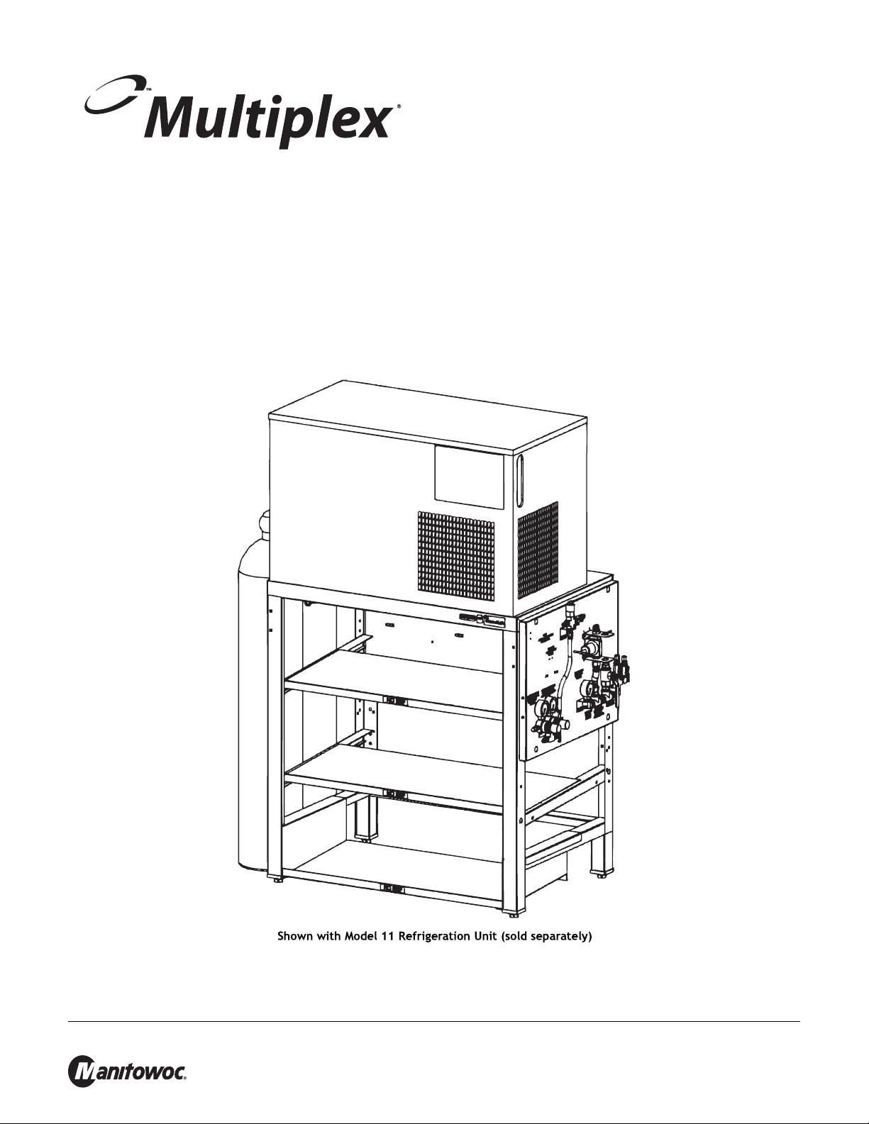
The Multiplex Model 2811 Bag-in-Box Support S tand is designed to accommodate nine (9) European syrup boxes.
The Model 2811 Bag-in-Box Support S t and measur es 260 mm (10.2") x 260 mm (10.2") x 400 mm (15.7"). T his stand
is also supplied with a C0
protective film on the stainless steel. Unpack the Stand and verify all components are included with the package. Peel
all the protective film off prior to proceeding with the set-up of the stand.
2 Tank Chain for securing the tanks to the side of the unit. The Stand is shipped with a
Manitowoc Foodservice Sellersburg, 2100 Future Drive, Sellersburg, IN 47172, Tel: 812-246-7000, www.manitowocbeverage.com
Page 2
Model 2811 Support Stand EI281129
!
Caution
!
Warning
To Avoid Serious Injury Read the following warnings before
beginning an installation. Falure to do so may result in possible
death or serious injury.
DO Adhere to all National and Local Plumbing and Electrical Safety Codes.
DO Turn “Off” incoming electrical service switches when servicing, installing, or repairing equipment.
DO Check that all flare fittings on the carbonation tank(s) are tight. This check should be performed with a
wrench to ensure a quality seal.
DO Inspect pressure on Regulators before starting up equipment.
DO Protect eyes when working around refrigerants.
DO Use caution when handling metal surface edges of all equipment.
DO Handle C0
DO Store C0
2 cylinders and gauges with care. Secure cylinders properly against abrasion.
2 cylinder(s) in well ventilated areas.
DO NOT Throw or drop a C0
DO NOT Connect the C0
possible death or injury . Best to connect th e C0
DO NOT Store C0
DO NOT Release C0
2 cylinders in temperature above 125˚ F (51. 7˚ C) near furnaces, radiator or sources of heat.
2 gas from old cylinder.
DO NOT Touch Refrigeration lines inside units, some may exceed temperatures of 200
2 cylinder. Secure the cylinder(s) in an upright position with a chain.
2 cylinder(s) directly to the product container . Doing so will result in an explosion causing
2 cylinder(s) to a regulator(s).
˚ F (93.3˚ C).
NOTE: Water pipe connections and fixtures directly connected to a potable water supply shall be sized, installed and
maintained in accordance with Federal, State, and Local codes.
DANGER OF ELECTRICAL SHOCK - Disconnect and lock out all
electrical power sources before performing service or maintenance on
this machine -- except when electrical tests are being performed by
qualified service personnel.
Manitowoc Foodservice Sellersburg, 2100 Future Drive, Sellersburg, IN 47172, Tel: 812-246-7000, www.manitowocbeverage.com
Page 3

Model 2811 Support Stand EI281129
INSTALLING THE SUPPORT STANDS
1. Place the Stand in the desired location approximately 8" (20.3 cm) from the wall where the equipment will be located.
2. Attach the Wall Anchor Bracket s to the rear legs of the sta nd using the bolt s, washers and nut s supplied with the S t and
(refer to Figure 1). Level the stand by adjusting the leg levelers located on all four (4) legs.
3. Note where the rear flanges of the Wall Anchor Brackets align with the wall surface. if the brackets can be securely
attached directly to the wall, do so with appropriate fasteners. Masonry walls will require anchors in drilled holes. S tud
framed walls may need a horizontal 2" x 4" stringer secured to the wall and anchored with lag screws into the wall studs.
Secure the wall brackets to the stringer with 1" screws (not provided) .
NOTE: Y ou must proper ly secure the stand to the wall to ensure safe ty.
4. While the stand has been designed and built to eliminate burrs and sharp edges, verify that all edges are smooth. Use a
file to remove any burrs that may have escaped the factory inspection.
HOW TO MOUNT THE REFRIGERATION UNIT TO THE SUPPORT STAND
1. Position the Multiplex refrigeration unit on the stan d and align holes in the unit base with holes in stand top. The water bath
drain should be over the large rectangula r hole in the stand to p.
2. The stand's installation p ackage includes appropriate screws for securi ng the refrigeration unit to th e stands. Only two (2)
screws are required to keep the unit from shifting position on the stand.
3. Use two (2) 5 / 8" x 1" Screws provided with the St and diagonally in opposite co rners to secure the Unit to the top of the
St and.
NOTE: Unit may overhang on the side of the stand in either direction or may be centered with equal overhang on both sides.
INSTALLING THE BAG-IN-BOX SUPPORT SHELVES
1. Locate the two (2) lower Shelf Brackets supplied with the stand. Note there are one left and right hand bracket s. Each
bracket slopes towards the front of the stand. Place the bracket on the lower side channel and slide it forward until it stops
at the front leg. Repeat this for the opposite side (refer to Figure 1).
2. Position the shorter shelf in the lower position with the flange in the rear facin g towards the floor . The shelf should be
pulled completely forward until the rear flange stops at the shelf bracket.
3. Position the remaining two (2) shelves across the Shelf Support Channels. The flange must be facing towards the floor
and it will fit into the slots in the shelf channel to position the Shelf in place (refer to Figure 1).
Manitowoc Foodservice Sellersburg, 2100 Future Drive, Sellersburg, IN 47172, Tel: 812-246-7000, www.manitowocbeverage.com
Page 4

Model 2811 Support Stand EI281129
MOUNTING THE C02 PANEL
(NOT SUPPLIED WITH ALL STANDS [REFER TO FIGURE 2])
1. Locate the C02 Panel carton which will have a stainless steel mounting plate taped to the carton. Remove the panel from
the carton and unpack the panel.
NOTE: Use caution when degrading packaging, the pane l includes installation materials for the complete system installation.
2. Remove the top Bag-in-Box shelf to allow access to the top and shelf channel of th e S t and.
3. Attach the Panel Mounting Plate to the bottom of the C0
mounting screws and nuts supplied with the stand.
4. Insert two (2) screws into the outside slots on the top right side of the stand and attach a nut to the backside of the screw.
Do not tighten the screw completely yet.
NOTE: The C0
5. Mount the C0
2 panel can be mou nted to the left side of the Stand by moving the C02 tank Chain to the rig ht side of the S tand.
2 Panel on the two (2) screws by inserting the screws through the keyhole slot at the top of the p anel.
Tighten the screws completely.
6. Attach the panel Mounting plate to the top shelf channel with two (2) ea ch of the mounting screws and n uts suppli ed with
the Stand.
7. Re-install the shelf and refer to the instructions supplied with the C0
2 Panel using the two (2) short slots and two (2) each of the
2 Panel for the remainder of the installa tion.
Manitowoc Foodservice Sellersburg, 2100 Future Drive, Sellersburg, IN 47172, Tel: 812-246-7000, www.manitowocbeverage.com
 Loading...