

Page 1
Soda Systems & SuperChil™
Refrigeration Units
Technician’s
Handbook
This manual is updated as new information and models
are released. Visit our website for the latest manual.
America’s Quality Choice in Refrigeration
Part Number STH12 9/10
www.manitowocfsg.com
Page 2

Page 3
Safety Notices
!
Warning
!
Caution
Important
As you work on Manitowoc equipment, be sure to pay
close attention to the safety notices in this handbook.
Disregarding the notices may lead to serious injury
and/or damage to the equipment.
Throughout this handbook, you will see the following
types of safety notices:
Text in a Warning box alerts you to a potential
personal injury situation. Be sure to read the
Warning statement before proceeding, and work
carefully.
Text in a Ca ution box alerts you to a situation in
which you could damage the equipment. Be sure
to read the Caution statement before proceeding,
and work carefully.
Procedural Notices
As you work on Manitowoc equipment, be sure to read
the procedural notices in this handbook. These notices
supply helpful information which may assist you as
you work.
Throughout this handbook, you will see the following
types of procedural notices:
Text in an Important box provides you with
information that may help you perform a
procedure more efficiently. Disregarding this
information will not cause damage or injury, but it
may slow you down as you work.
NOTE: T ext set off as a Note provides you with simple,
but useful, extra information about the procedure you
are performing.
Page 4
Read These Before Proceeding:
!
Caution
Important
! Warning
We reserve the right to make product
improvements at any time. S pecifications and
design are subject to change without notice.
Proper installation, care and maintenance are
essential for maximum performance and troublefree operation of your Manitowoc equipment. If
you encounter problems not covered by this
handbook, do not proceed, contact Manitowoc
Foodservice Group. We will be happy to provide
assistance.
Routine adjustments and maintenance
procedures outlined in this handbook are not
covered by the warranty.
PERSONAL INJURY POTENTIAL
Do not operate equipment that has been misused,
abused, neglected, damaged, or altered/modified
from that of original manufactured specifications.
Page 5

Table of Contents
General Information
Model Numbers . . . . . . . . . . . . . . . . . . . . .9
How to Read a Model Number . . . . . . . . .10
Accessories . . . . . . . . . . . . . . . . . . . . . . .10
Special Applications . . . . . . . . . . . . . . . .11
Model/Serial Number Location . . . . . . . .11
Warranty Information . . . . . . . . . . . . . . . .11
Installation
Pre-installation Checklist . . . . . . . . . . . . .13
Top Mounted Ice Maker Installations . . . 15
S250-M Dimensions . . . . . . . . . . . . . . . . .16
MII-250 Dimensions . . . . . . . . . . . . . . . . .18
MII-302 Dimensions . . . . . . . . . . . . . . . . .20
MII-250 Installation Kit . . . . . . . . . . . . . . .22
MII-302 Installation Kit . . . . . . . . . . . . . . .23
Refrigeration Units . . . . . . . . . . . . . . . . . .25
Safe Installation Dos and Don’ts . . . . . . .28
Location Requirements . . . . . . . . . . . . . .30
Electrical . . . . . . . . . . . . . . . . . . . . . . . . . .34
Plumbing/Water Supply . . . . . . . . . . . . . .38
Preparing Ice Bank – Non-ERC . . . . . . . .39
Preparing Ice Bank with ERC . . . . . . . . .41
Component Identification
Typical System . . . . . . . . . . . . . . . . . . . . .43
Connections . . . . . . . . . . . . . . . . . . . . . . .44
Maintenance
Maintenance Schedule . . . . . . . . . . . . . . .49
Cleaning and Sanitizing the Dispensing
Valves and Product Lines . . . . . . . . . . . .54
Sanitizing . . . . . . . . . . . . . . . . . . . . . . . . .58
Shipping, Storage and Relocation . . . . . 62
Operation
How the Multiplex Works . . . . . . . . . . . . .63
Differences Between the TS & SS Units .64
Equipment Setup Procedure (Non-ERC) 71
Part Number STH12 9/10 5
Page 6

Start-up (Non-ERC) . . . . . . . . . . . . . . . . . 72
Sequence of Operation (Non-ERC) . . . . 74
Start-up (with ERC) . . . . . . . . . . . . . . . . . 76
Sequence of Operation (with ERC) . . . . 78
Equipment Setup Procedure (with ERC) 82
Equipment Close Procedure — All Units 84
Troubleshooting
Electronic Refrigeration Control (ERC) Model
Error Codes . . . . . . . . . . . . . . . . . . . . . . . 87
Checklist . . . . . . . . . . . . . . . . . . . . . . . . . . 98
Problem Cross-reference Guide . . . . . . . 100
Gas System . . . . . . . . . . . . . . . . . . . 101
CO
2
Carbonated Water System . . . . . . . . . . . 104
Circulating System . . . . . . . . . . . . . . . . . 111
Compressed Air System . . . . . . . . . . . . . 112
Dispensing Valve and Tower . . . . . . . . . 114
Electrical System . . . . . . . . . . . . . . . . . . . 119
Refrigeration System . . . . . . . . . . . . . . . . 120
Syrup System . . . . . . . . . . . . . . . . . . . . . . 123
Water Booster System . . . . . . . . . . . . . . 125
Water Filter System . . . . . . . . . . . . . . . . . 127
When the Brix is OFF . . . . . . . . . . . . . . . 128
Component Check Procedures
Test Procedures: MPC 64A Timer/Selection
Pad . . . . . . . . . . . . . . . . . . . . . . . . . . . . . . 131
Dual Transformers . . . . . . . . . . . . . . . . . 133
New MPC84A Portion Control Board . . . 134
MOVs Field Testing . . . . . . . . . . . . . . . . . 140
Test Procedures: MPC84C Timer/Selection
Board . . . . . . . . . . . . . . . . . . . . . . . . . . . . 141
Back-flow Preventer Maintenance . . . . . 144
Head Pressure Control Valve . . . . . . . . . 145
Charging Multiplex Remote Refrigeration
Unit . . . . . . . . . . . . . . . . . . . . . . . . . . . . . . 147
Compressor & Remote Condenser . . . . 148
Agitator Condenser . . . . . . . . . . . . . . . . . 149
Carbonation System A or B . . . . . . . . . . 150
Circulation System A or B . . . . . . . . . . . 151
ERC Control Board, Keypad & Display . 152
Programming / Auto Set . . . . . . . . . . . . . 153
6 Part Number STH12 9/10
Page 7

ERC Component (Output) Connector Layout
154
ERC Sensor (Input) Connector Layout .154
Component Specifications
Refrigeration Unit Specifications . . . . . . 155
S-250M Specifications . . . . . . . . . . . . . . .156
MII-302 Specifications . . . . . . . . . . . . . . .156
Charts
Refrigerant Charge . . . . . . . . . . . . . . . . . .157
Operating Pressures . . . . . . . . . . . . . . . .161
McDonald’s Models History . . . . . . . . . . .163
Sustained Draw Curve Chart s . . . . . . . . .164
Diagrams
Wiring Diagrams . . . . . . . . . . . . . . . . . . . .167
Soda Wiring Diagrams . . . . . . . . . . . . . . .185
Super-Chil Wiring Diagrams . . . . . . . . . .200
Circuit Schematics . . . . . . . . . . . . . . . . . .212
Ice/Beverage Units Diagrams . . . . . . . . .231
Part Number STH12 9/10 7
Page 8

8 Part Number STH12 9/10
This Page Intentionally Left Blan k
Page 9
General Information
Model Numbers
This manual covers the following models:
(A) Air Cooled (W) Water Cooled (R) Remote Cooled
2803A04 2803W04 2803R04
2803AX04 2803WX04 2803RX04
2803A04 2803W04 2803R04
11MA04 11MW04 11MR04
11MAX04 11MAW04 11MRX04
11MA04 11MW04 11MR04
42MA04 42MW04 42MR04
42MAX04T 42MWX04T 42MRX04T
44MA04 44MW04 44MR04
44MAX04T 44MWX04T 44MRX04T
44EAX04T 44EWX04T 44ERX04T
50MA04 50MW04 50MR04
50MAX04 50MWX04 50MRX04
50MA04Q/T 50MW04Q/T 50MR04Q/T
SC180A SC180W SC180R
SC180AX SC180WX SC180RX
SC340A SC340W SC340R
SC340AX SC340WX SC340RX
SC1000A SC1000W SC1000R
SC1000AX SC1000WX SC1000RX
SC2000A SC2000W SC2000R
SC2000AX SC2000WX SC2000RX
Ice/Beverage Dispensers
MII-302 S-250M
Part Number STH12 9/10 9
Page 10
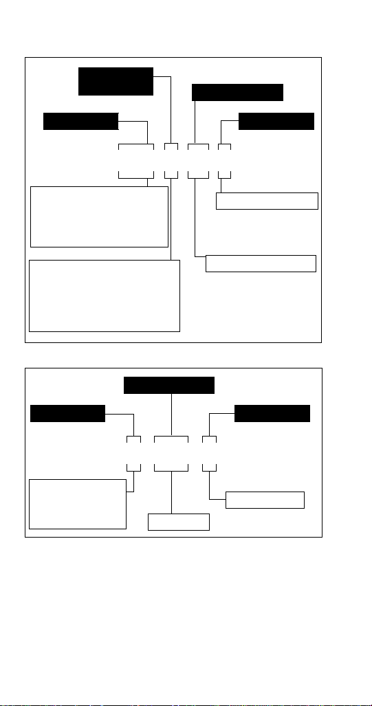
How to Read a Model Number
Special Configuration
04 - R404a refrigerant
Model Prefix
Model Suffix
Model Base
11M A 04 x
A - Air-cooled
AX - Air-cooled, international
R - Remote
RX - Remote, international
W - Water-cooled
WX - Water-cooled, international
Condenser
Type
2803 & SC180 - 1/3 hp
11M & SC340 - 1/2 hp
44M, 42M & SC1000 - 1 hp
44E - 1 hp, TUV Approved
50M & SC2000 - 2.2 hp
S - Ice/Beverage
Dispenser
MII - Ice/Beverage
Dispenser
M - Multiplex
Ice Capacity
Model Prefix Model Suffix
Model Base
S–250–M
ICE/BEVERAGE MODEL NUMBERS
Accessories
Depending on store type and location, various optional
equipment (such as CO
booster kit, etc.) may be added to this system. Install
and connect any optional equipment in the desired
location according to the installation instructions
provided with these kits/equipment.
10 Part Number STH12 9/10
Panel, water filter kit, water
2
Page 11
Special Applications
!
Warning
!
Warning
ATTENTION: MARINE INSTALLATIONS
This unit is for use on vessels over 66 ft (20 m) in
length. This unit must not be installed in the engine
space of a gasoline-powered ship.
NOTE: This unit must be secured to the vessel during
installation. Models with part numbers beginning with
the letters TS are NOT marine listed.
OUTDOOR APPLICATIONS
TS Multiplex Beverage Recirculating units are
approved and listed by Underwriters Laboratories
(UL). However they are not UL approved for weather
exposure applications. These units must be installed in
areas where adequate protection from the elements is
provided, all other models are ETL listed.
Personal Injury Potential
Do not operate equipment that has been misused,
abused, neglected, damaged, or altered/modified
from that of original manufactured specifications.
Model/Serial Number Location
These numbers are required when requesting
information from your local Manitowoc Distributor,
service representative, or Manitowoc Foodservice.
The model and serial number are listed on the
OWNER WARRANTY REGISTRATION CARD. They
are also listed on the MODEL/SERIAL NUMBER
DECAL affixed to the unit.
Warranty Information
Consult your local distributor for terms and conditions
of your warranty. Your warranty specifically excludes
all beverage valve brixing, general adjustments,
cleaning, accessories and related servicing.
Part Number STH12 9/10 11
Page 12

Your warranty card must be returned to activate the
warranty on this equipment. If a warranty card is not
returned, the warranty period can begin when the
equipment leaves the factory.
No equipment may be returned without a written
Return Materials Authorization (RMA). Equipment
returned without an RMA will be refused at the dock
and returned to the sender at the sender’s expense.
Please contact your local distributor for return
procedures.
12 Part Number STH12 9/10
Page 13
Installation
Pre-installation Checklist
When installing any system, first make sure the major
components are available. Generally the major
components necessary for an installation are:
B-I-B System also:
B-I-B connectors
B-I-B regulator set
B-I-B rack
B-I-B syrup boxes
Bulk Syrup System also:
Syrup connectors for Bulk tank
Gas connectors for Bulk tank
Bulk syrup tanks
Part Number STH12 9/10 13
Page 14
Post Mix System:
CO2 regulator set
Beverage dispenser
Beverage tubing
CO
tank
2
Carbonator
Stepless (Oetiker) clamps
Chain for CO
tank
2
Double Check:
Do you have enough space to install the
dispenser or a dispenser and top mounted
cuber?
Does top mounted cuber (if utilized) have a
minimum of 6 inches (15.3 cm) clearance on
all sides?
Is the countertop level?
Can the countertop support the weight of the
dispenser, or the dispenser/cuber
combination plus the weight of the stored
ice?
14 Part Number STH12 9/10
Page 15
Also consider the location of the following items before installa tio n:
Water line
Drain
Power outlet
Heating and air conditioning ducts
Top Mounted Ice Maker Installations
Location — Avoid placing the dispenser
and/or ice machine near heat sources such
as radiators, ovens, refrigeration equipment
and direct sunlight.
Clearances — Six inch (15.2 cm) clearance
on all sides of the icemaker is needed.
Front of icemaker to be flush with front of
dispenser — The front of the icemaker must
be flush with the front of the dispenser. When
the icemaker is flush with the front of the
dispenser, some icemakers may overhang at
the back of the dispenser.
Drains — A separate drain line is required
for the ice machine, in addition to a drain line
for the ice/beverage dispenser.
Dispensers require an adapter kit to install
some top-mounted icemakers. Contact your
local distributor for the correct adapter kit.
Part Number STH12 9/10 15
Page 16
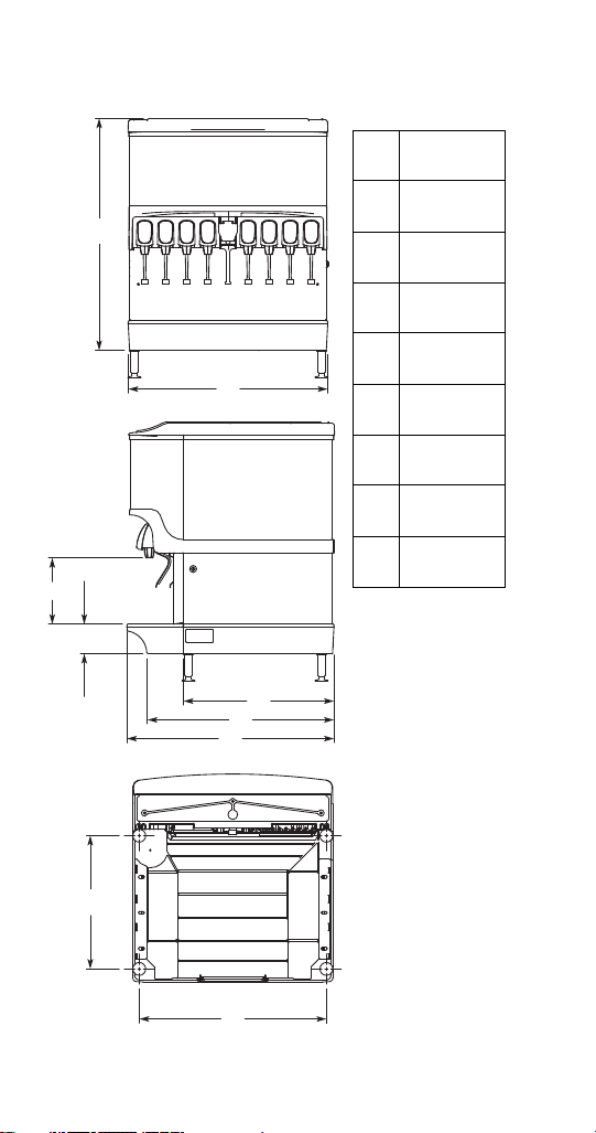
S250-M Dimensions
I
H
B
A
E
F
G
D
C
A
39.81"
(101.1 cm)
B
30.00"
(76.2 cm)
C
9.94"
(25.2 cm)
D
4.44"
(11.3 cm)
E
22.63"
(57.5 cm)
F
28.00"
(71.1 cm)
G
31.13"
(79.1 cm)
H
20.00"
(50.8 cm)
I
27.44"
(69.7 cm)
16 Part Number STH12 9/10
Page 17
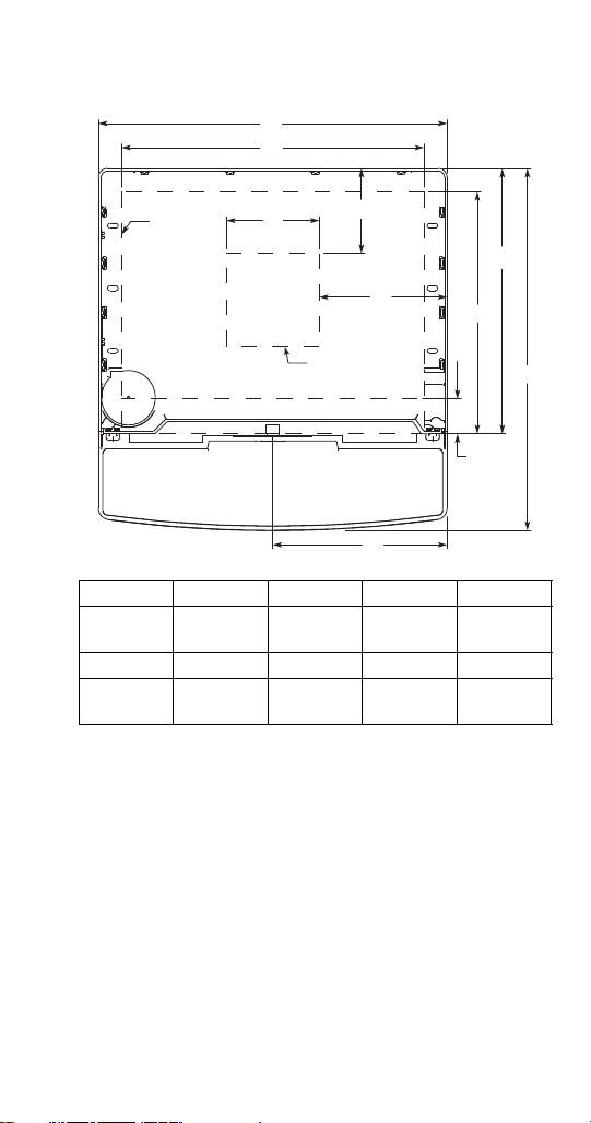
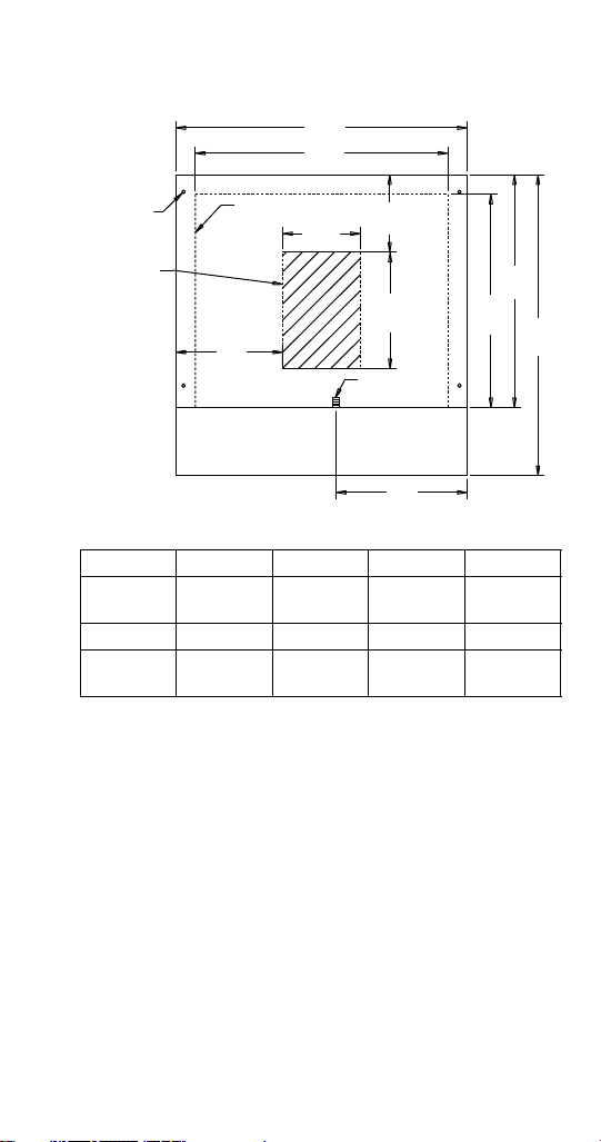
S250-M FOOTPRINT
A
B
D
C
E
G
I
J
H
F
Minimum Area
for Cutout
Maximum
Area for
Cutout
ABCDE
30.00"
(76.2 cm)
FGHI J
15.00"
(38.1 cm)
26.00"
(66.0 cm)
20.81"
(52.8 cm)
8.00"
(20.3 cm)
3.00"
(7.6 cm)
7.30"
(18.5 cm)
22.81"
(57.9 cm)
11.00"
(27.9 cm)
31.13"
(79.1 cm)
Part Number STH12 9/10 17
Page 18
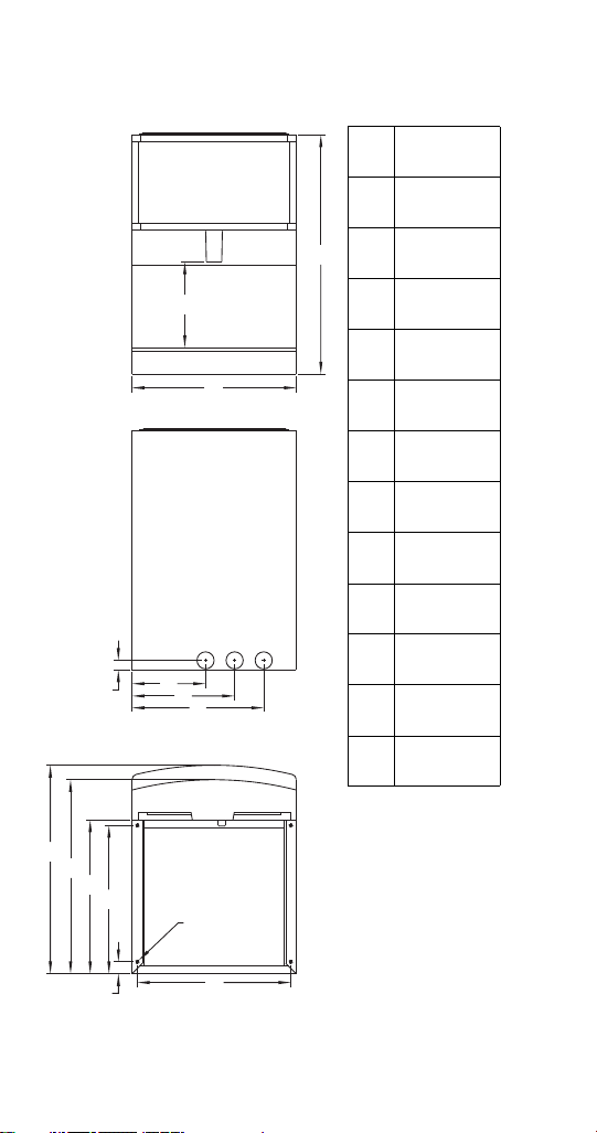
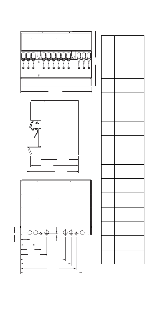
MII-250 Dimensions
A
A
39.00"
(99.1 cm)
B
12.50"
(31.8 cm)
C
30.00"
(76.2 cm)
D
1.50"
(3.8 cm)
E
9.94"
(25.2 cm)
F
13.50"
(34.3 cm)
G
20.00"
(50.8 cm)
H
30.50"
(77.5 cm)
K
28.38"
(72.1 cm)
L
22.50"
(57.2 cm)
M
21.69"
(55.1 cm)
N
1.75"
(4.4 cm)
P
28.44"
(72.2 cm)
Front View
Back View
Bottom View
3/8"-16
Thread
Mounting
Holes for
optional
legs
B
C
M
E
F
G
D
H
K
L
P
N
18 Part Number STH12 9/10
Page 19
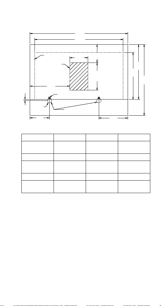
MII-250 FOOTPRINT
A
B
C
Maximum Area
for Cutout
D
F
E
3/4" NPT
Fitting
Drainpan
G
H
I
J
3/8"-16
Thread
Mounting
Holes for
Optional
Legs
Minimum
area for
Cutout:
Install
conduit to
the back of
opening to
allow
forward
movement
for service
of flex
manifold.
ABCDE
30.00"
(76.2 cm)
FGHI J
12.00"
(30.5 cm)
26.00"
(66.0 cm)
13.50"
(34.3)
8.00"
(20.3 cm)
22.00"
(55.9cm)
8.00"
(20.3 cm)
24.00"
(61.0 cm)
11.00"
(27.9 cm)
31.00"
(78.7 cm)
Part Number STH12 9/10 19
Page 20
MII-302 Dimensions
A
33.25"
(84.5 cm)
B
12.50"
(31.8 cm)
C
42.75"
(108.6 cm)
D
1.38"
(3.5 cm)
E
5.59"
(14.2 cm)
F
9.10"
(23.1 cm)
G
12.16"
(30.9 cm)
H
31.00"
(78.7)
J
15.78"
(40.1 cm)
K
28.78"
(73.1 cm)
L
22.50"
(57.2 cm)
M
0.82"
(2.1 cm)
N
26.97"
(68.5 cm)
O
30.47"
(77.4 cm)
P
33.75"
(85.7 cm)
Q
37.16"
(94.4 cm)
B
C
L
K
H
D
E
F
G
J
O
Q
M
N
P
A
20 Part Number STH12 9/10
Page 21
MII-302 FOOTPRINT
A
B
C
Maximum Area
for Cutout
D
F
E
3/4" NPT Fitting
Drainpan
H
I
J
K
Minimum area
for Cutout: Install
conduit to the back of
opening to allow forward
movement for service of
flex manifold.
Cutouts for Extended
Splash Panel Drain Tube
G
0.50
(1.3)
ABCD
42.75"
(108.6 cm)
EFGH
17.38"
(44.1 cm)
IJK
20.50"
(52.1 cm)
38.75"
(98.4 cm)
12.00"
(30.5 cm)
24.00"
(61.0 cm)
8.00"
(20.3 cm)
8.54"
(21.7 cm)
31.00"
(78.7 cm)
8.00"
(20.3 cm)
12.63"
(32.1 cm)
Part Number STH12 9/10 21
Page 22
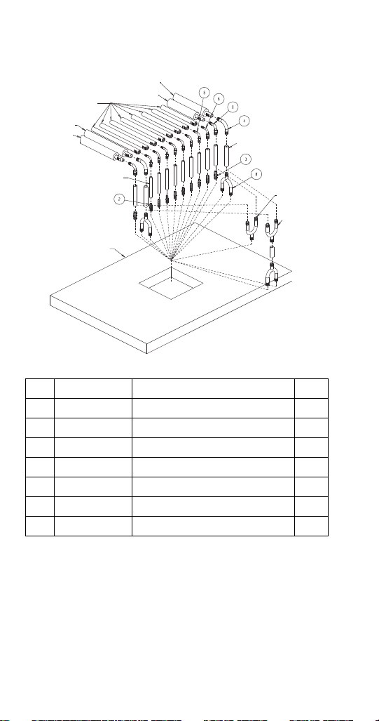
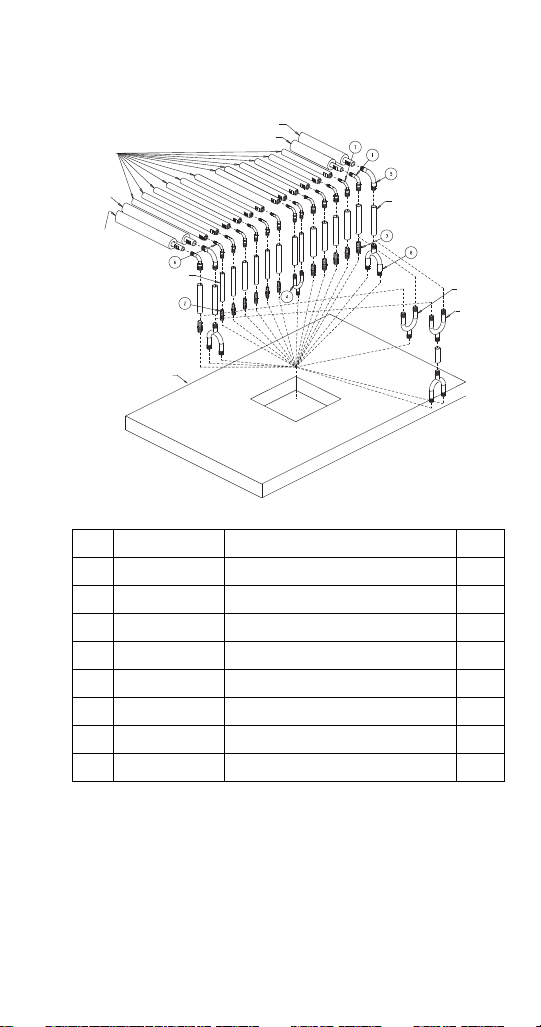
MII-250 Installation Kit
Carb Water to
Left Manifold
Plain Water to
Left Manifold
Syrup Tubes
to Valves
Carb Water to
Right Manifold
Plain Water to
Right Manifold
3/8" ID Tubing
from Conduit (7X)
1/2" ID Tubing
from Conduit (5X)
Use Only for
One Conduit
Plain Water
Line
Use Only for
Two Conduit
Carb Water
Line
Countertop
To Conduit
No. Part Number Description Qty.
1 00854998 Ell 1/2 x 3/8 Barb SS 2
2 00861304 Splicer 3/8 x 3/8 Barb 7
3 00861306 Splicer 1/2 x 1/2 Barb 3
4 5018595 Splicer Elbow SS 1/2 x 1/2 2
5 5030996 Elbow 1/4 x 3/8 Barb SS 7
6 5030997 Elbow 1/4 x 1/2 Barb SS 1
7 5030998 U-bend 1/2 x 1/2 WI - 1/2 Stem 3
22 Part Number STH12 9/10
Page 23
Carb Water to
Left Manifold
Plain Water to
Left Manifold
Syrup Tubes
to
Valves
Carb Water
to Right
Manifold
Plain Water
to Right
Manifold
3/8" ID Tubing
from Conduit (7X)
1/2" ID Tubing
from Conduit (9X)
Use Only
for One
Conduit
Plain
Water
Line
Use Only
for Two
Conduit
Carb
Water
Line
Countertop
To Conduit
MII-302 Installation Kit
No. Part Number Description Qty.
1 00854998 Ell 1/2 x 3/8 Barb SS 2
2 00861304 Splicer 3/8 x 3/8 Barb 6
3 00861306 Splicer 1/2 x 1/2 Barb 6
4 5011751 Fitting 3/8" Y Barb 1
5 5018595 Splicer Elbow SS 1/2 x 1/2 2
6 5030996 Elbow 1/4 x 3/8 Barb SS 8
7 5030997 Elbow 1/4 x 1/2 Barb SS 4
8 5030998 U-bend 1/2 x 1/2 WI - 1/2 Stem 3
WATER AND SYRUP LINES
This kit facilitates connecting the unit to a 12-16 line
conduit, with one or two carbonated water recirculating
systems, and one or two plain water supply lines, and
maximum 8 syrup product lines.
The unit is shipped with connecting lines terminating
under the unit. It will be necessary to make a 90° turn
Part Number STH12 9/10 23
Page 24

down through the counter top, to connect to the
conduit. It will also be necessary to fully insulate this
new added section before passing through the counter
top, or before hooking to main conduit.
CARB WATER LINES
• Unit has two carb water lines, one for each flex
manifold.
• Use 2 @ 1/2" x 1/2" elbow and 6-12" of 1/2"
conduit tubing to make connection bend from unit
down through hole in counter top, to mate with
conduit.
• Conduit with only two circulating carb water lines.
• Use two @ 1/2" barb U-bend adapters (invert one)
to connect the two carb circulating lines from
conduit to the two carb water lines from the unit.
Use short 1/2" conduit line to connect the two
U-bends as shown (item #8).
• Conduit with four, two sets of recirculating carb
water lines.
• Use two @ 1/2" barb U-bend adapters, to connect
each set of circulating conduit lines to each carb
water line from unit as shown (8).
PLAIN WATER LINES
• Unit has two plain water lines, one for each flex
manifold.
• Use two @ 3/8" x 1/2" elbows and 6-12" of 1/2"
conduit tubing to make connection bend from unit
down through hole in counter top, to mate with
conduit.
• Conduit with only one plain water line.
• Use one @ 1/2" U-bend adapter, to connect the
two plain water lines to one plain water line from
conduit (item #3).
• Conduit has two plain water lines.
• Use two @ 1/2" straight adapters to connect each
plain water line from unit to each plain water line
from conduit as shown (3).
24 Part Number STH12 9/10
Page 25

SYRUP LINES
• Unit has eight syrup lines.
• Use seven @ 1/4 x 3/8" and one @ 1/4 x 1/2"
elbows and proper size conduit tubing to make
connection bend from unit down through hole in
counter top, to mate with conduit.
• FULLY INSULATE (no air gaps) and finish with
tape wrap, all these connections from unit, through
90° bend connection and down close to straight
conduit connection. Locate unit properly on
counter, and secure to counter . Finish connections
to conduit with 3/8" x 3/8" and 1/2" x 1/2" straight
barb connectors, and U-bend adapters, as
needed.
• FULLY INSULATE and finish with tape wrap all
these connections to the conduit.
Refrigeration Units
• Refrigeration units require stand or 6" (15.2 cm)
legs. Refrigeration unit cannot be placed directly
on floor.
• Conduit can be run through floor or ceiling chase.
• Syrup supply can be located on stand or adjacent
to refrigeration unit.
CLEARANCES
Control Side (Right) 18" (45.7 cm)
Tower Connection Side (Left) 12" (30.5 cm)
Back Side 6" (15.2 cm)
Ceiling 18" (45.7 cm)
Part Number STH12 9/10 25
Page 26

REMOTE CONDENSER LINESET REQUIREMENTS
Important
Important
If you have a MAC Multi-Pass condenser please
add three (3) pounds additional charge.
If you exceed the 100ft line set length add
.72oz/ft of line set run (one way) for every foot
over 100ft, to the UNIT charge
1. Both the discharge and liquid remote condensing
lines must be kept to a minimum distance for
maximum performance. All Multiplex systems are
capacity rated to 100 ft (30.5 m) tubing distance
between the compressor and condenser. If you
have another brand condenser, please add
additional charge for the condenser (example: up
to three (3) pounds for a MAC condenser).
2. Any vertical ri se 25 ft (7.62 m) or greater must
have a manufactured or installed trap (bend), in
the discharge refrigeration line from the
compressor to the remote condenser. A trap is
necessary for every additional 25 ft (7.62 m)
vertical rise. When excessive vertical rise exists,
this trap allows oil to reach the condenser and
return to the compressor.
26 Part Number STH12 9/10
Page 27
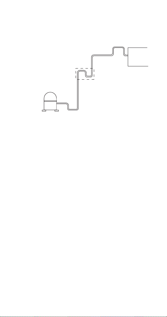
3. The easiest method to create a trap is to bend the
To the
Condenser
Discharge Line Trap Every
25 Vertical ft. (7.62 m)
3 ft (.9 m) (minimum) of Discharge
Line Trap at the Compressor
Compressor
3" (7.6 cm) x 6" (15.2 cm)
Maximum Trap Area
Discharge Line
Condenser Trap
tubing (smoothly , no kinks) into the trap form.
4. The trap(s) must be of minimum height of 3"
(7.6 cm) and a width of 6" (15.2 cm) to minimize oil
accumulation. The traps can also be bent out of the
refrigeration tubing. Carefully bend the tubing down
12", and then sweep the tubing back up.
5. It is critical that the remote condensing line size
specifications for the specific model be
maintained. The specifications are 1/2" discharge
and 3/8" liquid lines.
Part Number STH12 9/10 27
Page 28
Safe Installation Dos and Don’ts
! Warning
!
Warning
! Warning
Read the following warnings before beginning an
installation. Failure to do so may result in
possible death or serious injury.
• Adhere to all National and Local Plumbing
and Electrical Safety Codes.
• Turn OFF incoming electrical service
switches when servicing, installing, or
repairing equipment.
DO NOT throw or drop a CO
•
Secure the cylinder(s) in an upright position
with a chain.
DO NOT store CO
•
above 125°F (51.7°C) near furnaces, radiator
cylinders in temperature
2
or sources of heat.
cylinder.
2
DO NOT connect the CO
the product container. Doing so will result in an
cylinder(s) directly to
2
explosion causing possible death or injury. It is best
to connect the CO
cylinder(s) to a regulator(s).
2
Carbon Dioxide (CO2) displaces oxygen. Exposure
to a high concentration of CO
which are followed rapidly by loss of consciousness
and suffocation. If a CO
particularly in a small area, immediately ventilate the
area before repairing the leak. CO
must not be installed in an enclosed space. An
gas causes tremors,
2
gas leak is suspected,
2
lines and pumps
2
enclosed space can be a cooler or small room or
closet. This may include convenience stores with
glass door self serve coolers. If you suspect CO
may build up in an area, venting of the BIB pumps
and/or CO
28 Part Number STH12 9/10
monitors must be utilized.
2
2
Page 29

• DO check that all flare fittings are tight. This check
must be performed with a wrench to ensure a
quality seal.
• DO inspect pressure on regulators before starting
up equipment.
• DO protect eyes when working around
refrigerants.
• DO use caution when handling metal surface
edges of all equipment.
• DO handle CO
Secure cylinders properly against abrasion.
• DO store CO
• DO NOT exhaust CO
into an enclosed area, including all types of walk-in
cylinders and gauges with care.
2
cylinder(s) in well ventilated areas.
2
gas (example: syrup pump)
2
coolers, cellars, and closets.
• DO NOT release CO
gas from old cylinder.
2
• DO NOT touch refrigeration lines inside units;
some may exceed temperatures of 200°F
(93.3°C).
NOTE: All utility connections and fixtures must be
sized, installed, and maintained in accordance with
Federal, State, and Local codes.
Part Number STH12 9/10 29
Page 30
Location Requirements
Number of Dispensing Stations
Business Level* 1 2 3 4
Up to 6 gal / 3 L
of syrup/day or
280 drinks/day
(2,000 gal/yr)
Model 2803
40 ft / 12 m
Maximum
Conduit Length
Model 11M
100 ft / 30 m
Maximum
Conduit Length
Model 44M
250 ft / 80 m
Maximum
Conduit Length
Model 44M
250 ft / 80 m
Maximum
Conduit Length
Up to 12 gal / 45 L
of syrup/day or
560 drinks/day
(4,000 gal/year)
Model 11M
100 ft / 30 m
Maximum
Conduit Length
Model 11M
100 ft / 30 m
Maximum
Conduit Length
Model 44M
250 ft / 80 m
Maximum
Conduit Length
Model 44M
250 ft / 80 m
Maximum
Conduit Length
Up to 21 gal / 79 L
of syrup/day or
980 drinks/day
(7,500 gal/yr)
Model 44M
250 ft / 80 m
Maximum
Conduit Length
Model 44M
250 ft / 80 m
Maximum
Conduit Length
Model 44M
250 ft / 80 m
Maximum
Conduit Length
Model 44M
250 ft / 80 m
Maximum
Conduit Length
Up to 32 gal / 121 L
of syrup/day or
1400 drinks/day
(11,500 gal/yr)
Model 44M
250 ft / 80 m
Maximum
Conduit Length
Model 44M
250 ft / 80 m
Maximum
Conduit Length
Model 50M
350 ft / 107 m
Maximum
Conduit Length
Model 50M
350 ft / 107 m
Maximum
Conduit Length
Up to 42 gal / 159 L
of syrup/day or
2000 drinks/day
(15,000 gal/yr)
Model 50M
350 ft / 107 m
Maximum
Conduit Length
Model 50M
350 ft / 107 m
Maximum
Conduit Length
Model 50M
350 ft / 107 m
Maximum
Conduit Length
Model 50M
350 ft / 107 m
Maximum
Conduit Length
* Care must be taken when selecting the proper refrigeration unit. Above selections are for 75°F
(24°C) conditions, 16 ounce (470 ml) drinks, and average business cycles. Other factors such as
lunch or dinner peak periods, large drinks, or high ambient conditions may require the next larger
size unit. Contact your Manitowoc Company Author ized Distributor or Manitowoc Bever age Systems
(MBS) for more information.
SODA REFRIGERATION UNIT “QUICK-PICK” SELECTION CHART
30 Part Number STH12 9/10
Page 31

Select a location for the refrigeration unit that meets
the requirements of the building plans, local codes,
and personnel. The unit must be positioned for free
airflow as well as for future service. The following
minimum requirements must be met:
• 100 GPH (379 LTR/hr) potable water supply
Models 2803/11/38; 200 GPH (757 L TR/hr) potable
water supply Models 44/50
• Beverage quality CO
with a minimum 3/8" (.96 cm) line
gas (bulk or bottled supply)
2
• One Bag-In-Box (BIB) container of each post mix
syrup flavor.
NOTE: Refer to nameplate on side of refrigeration unit
for voltage and amperage specifications. Make all
electrical connections at the junction box located at the
top rear of unit. Optional equipment may require
additional power supplies.
NOTE: Potable water connections to the equipment
must comply with local plumbing code requirements,
particularly the back-flow prevention requirements.
PLUMBING REQUIREMENTS – GENERAL
Incoming water supply must be provided before
installation of the refrigeration unit and must comply
with local plumbing requirements.
1. A minimum 1" (2.54 cm) water supply line with a
manual shut-off valve must be plumbed at least
6 ft (183 cm) from the unit. The incoming water
supply pressure must not exceed 70 psi static
(4.8 bar) and be no less than 40 psi (2.8 bar)
dynamic. If supply water pressure is greater than
70 psi (5 bar), a water regulator will be required.
2. Locate the drain hose, bracket, and two screws
provided in the installation kit. Attach the drain
hose to the water bath overflow tube located on
the bottom of the refrigeration unit.
Part Number STH12 9/10 31
Page 32

3. Connect the water manifold supply line, located
Screw
Drain Hose
Bottom
of Unit
Bracket
on the bulkhead panel in the motor compartment
to the main water supply. The main water supply
shut-off valve must remain in the OFF position. If
a water filter is to be installed, connect the line to
the outlet fitting of the filter. Plumb according to
applicable plumbing codes.
Drain Hose Connection
4. When a water coole d conde nser is installed, a
copper supply line (not supplied with unit) must be
plumbed to the 3/8" (.965 cm) male flare fitting
installed in the water shut-off assembly. The
shut-off must be placed in the OFF position. A
copper drain line (not supplied) is to be connected
to the outlet fitting of the water cooled condenser
and routed to the floor drain.
32 Part Number STH12 9/10
Page 33

WATER SUPPLY
1. Use the built in fill valv e that is already plumbed
into the unit.
2. An appropriate floor drain is required within 6 ft
(2 m) of the unit.
3. Potable water connections to the equipment must
comply with the basic plumbing code of the
Building Officials and Code Administrators
International, Inc. (BOCA) and the Food Service
Sanitation Manual of the Food and Drug
Administration. Verify local plumbing code
requirements.
Part Number STH12 9/10 33
Page 34

Electrical
! Warning
GENERAL
All wiring must conform to local, state and
national codes.
MINIMUM CIRCUIT AMPACITY
The minimum circuit ampacity is used to help select
the wire size of the electrical supply. (Minimum circuit
ampacity is not the unit’s running amp load.) The wire
size (or gauge) is also dependent upon location,
materials used, length of run, etc., so it must be
determined by a qualified electrician.
ELECTRICAL REQUIREMENTS
Refer to unit’s Model/Serial Plate for
voltage/amperage specifications.
34 Part Number STH12 9/10
Page 35

SPECIFICATIONS
* Only the model 50M with SS part numbers have 120V components, the TS does not.
Model Volt/Cycle/Phase
Minimum
Circuit Amps
Breaker Compressor
2803 &
SC180
120/60/1
230/50/1
20.3
9.0
25A
16A
1/3 hp
.46 kW
11M &
SC340
120/60/1
230/50/1
21.5
10.7
30A
16A
1/2 hp
.97 kW
44M,
42M &
SC1000
208-230/60/1
230/50/1
20.6
20.6
30A
25A
1 hp
1.9 kW
50M 120* /208-230/60/3
230/400/50/3
25.2
11.6
30A
20A
2.2 hp
2.0 kW
SC2000 208-230/60/3
230/400/50/3
25.2
11.6
20A
15A
2.2 hp
2.0 kW
Part Number STH12 9/10 35
Page 36

GROUNDING INSTRUCTIONS
! Warning
!
Warning
The unit must be grounded in accordance with
national and local electrical codes.
This appliance must be grounded. In the event of
malfunction or breakdown, grounding provides a path
of least resistance for electric current to reduce the risk
of electric shock.
NOTE: The refrigeration units are not equipped with a
cord.
Improper connection of the equipment-grounding
conductor can result in a risk of electric shock.
The conductor with insulation having an outer
surface that is green with or without yellow stripes
is the equipment grounding conductor. If repair or
replacement of the cord or plug is necessary, do
not connect the equipment-grounding conductor
to a live terminal. Check with a qualified
electrician or serviceman if the grounding
instructions are not completely understood, or if
in doubt as to whether the appliance is properly
grounded. Do not modify the plug provided with
the appliance — if it will not fit the outlet, have a
proper outlet installed by a qualified electrician.
36 Part Number STH12 9/10
Page 37

!
Warning
When using electric appliances, basic
precautions must always be followed, including
the following:
a. Read all the instructions before using the
appliance.
b. T o reduce the risk of injury , close supervision
is necessary when an appliance is used near
children.
c. Do not contact moving parts.
d. Only use attachments recommended or sold
by the manufacturer.
e. Do not use outdoors.
f. For a cord-connected appliance, the
following shall be included:
• Do not unplug by pulling on cord. To
unplug, grasp the plug, not the cord.
• Unplug from outlet when not in use and
before servicing or cleaning.
• Do not operate any appliance with a
damaged cord or plug, or after the
appliance malfunctions or is dropped or
damaged in any manner. Contact the
nearest authorized service facility for
examination, repair, or electrical or
mechanical adjustment.
g. For a permanently connected appliance —
Turn the power switch to the off position
when the appliance is not in use and before
servicing or cleaning.
h. For an appliance with a replaceable lamp —
Always unplug before replacing the lamp.
Replace the bulb with the same type.
i. For a grounded appliance — Connect to a
properly grounded outlet only. See
Grounding Instructions.
Part Number STH12 9/10 37
Page 38

Plumbing/Water Supply
PLUMBING POTABLE WATER
Model
2803 &
SC180
11M &
SC340
44M,
42M &
SC1000
50M 40 – 70 psig
SC2000 40 – 70 psig
Required
Water
Pressure
40 – 70 psig
(2.8 – 4.9 bar)
40 – 70 psig
(2.8 – 4.9 bar)
40 – 70 psig
(2.8 – 4.9 bar)
(2.8 – 4.9 bar)
(2.8 – 4.9 bar)
A 1" (2.54 cm) ID copper inlet water line equipped with
a 3/4" (1.905 cm) FPT adapter with shut-off must be
supplied by plumber at rear of equipment. Appropriate
floor drains must be provided within 6 ft (183 cm) of
each unit installed.
NOTE: The carbonator in this unit is provided with a
dual check valve type back-flow preventer, which
conforms to ASSE 1032. The Model 50M & 44M
vented backflow preventer conforms to ASSE 1022.
Potable water connections to the equipment must
comply with the basic plumbing code of the Building
Officials and Code Administrators International, Inc.
(BOCA) and the Food Service Sanitation Manual of
the Food and Drug Administration. Verify local
plumbing code requirements.
Drain
Connections
3/4" ID
within 6 ft (2 m)
3/4" ID
within 6 ft (2 m)
3/4" ID
within 6 ft (2 m)
3/4" ID
within 6 ft (2 m)
3/4" ID
within 6 ft (2 m)
Water
Supply
3/8" ID
EVA Line
3/8" ID
EVA Line
1/2" ID
EVA Line
1/2" ID
EVA Line
1/2" ID
EVA Line
38 Part Number STH12 9/10
Page 39

Preparing Ice Bank – Non-ERC
Drain Tube
Overflow
Tube
Wate r Bath
Tank
Tab
Clamp
BUILDING AN ICE BANK
1. At this time, fill the unit water bath tank to the top,
or within 1/2" (1.3 cm) of the top minimum, of the
overflow tube. Use a garden hose or another
water supply to do this.
NOTE: A manual fill valve is incorporated into the
water circuit to the carbonator tank. This valve can be
used to manually add water lost for any reason. Do not
leave this valve ON constantly, only use it for filling and
topping off. The water bath must be drained, flushed,
and refilled every six months.
2. Turn ON the switch labeled “Refrigeration”. Allow
unit to run for about 15 minutes before proceeding
to step 3.
3. Turn ON the switch labeled “Agitator”.
NOTE: Turn this switch OFF to perform any operations
in the water bath area.
With water bath water temperature of 65°F (18°C), ice
will begin to form on the evaporator coils in
approximately 2 hours. The unit will build a full ice
bank in approximately 4 to 6 hours (depending on
ambient water temperature).
4. Before turning on the carbonator or circulator
switch, verify that the pump box assembly has
been mounted and connected to the unit and the
appropriate syrup and water has been supplied.
Part Number STH12 9/10 39
Page 40

5. Turn on the main water supply to the booster
Important
assembly. Verify the booster is plugged in and
that the accumulator tank valve is open. (If the
system has an optional “Out-of-Syrup” device,
verify that it is unplugged.)
6. Verify the pump is running. Place the valve on the
right side of the pump box in the purge position
until all air bubbles have passed through the line.
Turn the valve back to “dispense”. Plug the
Out-of-Syrup device power cord into an
appropriate wall outlet at this time (if supplied).
NOTE: Verify that the pump box holding tank is full
before proceeding.
7. Turn on the circulator and carbonator switches.
The carbonator must run for approximately 1 to 3
minutes and shut off. The circulator must run
continuously. Verify that water is returning to the
water bath through the return bulk head fitting.
Wait until a thin layer of ice has begun to form on
the evaporator before proceeding any further.
8. Go to the tower(s) and brix th e valves. Using a
syrup separator and volume cup, adjust the flow
rate of the carbonated water to two fluid ounces
per second. Then, using the separator and a brix
cup, adjust the syrup flow rate for a ratio of
carbonated water to syrup.
40 Part Number STH12 9/10
Page 41

Preparing Ice Bank with ERC
Drain Tube
Overflow
Tube
Wate r Bath
Tank
Tab
Clamp
BUILDING AN ICE BANK
1. At this time, fill the unit water bath tank to the top,
or within 1/2" (1.3 cm) of the top minimum, of the
overflow tube. Use a garden hose or another
water supply to do this.
NOTE: A manual fill valve is incorporated into the
water circuit to the carbonator tank. This valve can be
used to manually add water lost for any reason. Do not
leave this valve ON constantly, only use it for filling and
topping off. The water bath must be drained, flushed,
and refilled every six months.
2. Main power to unit must be on. Power delay of 30
seconds occurs when power applied. “Pd30”
3. Press COMP/AGIT switch on keypad display.
4. Agitator will come on immediately and
compressor delay will start. “Cd99” will count from
180 to 0.
NOTE: Turn this switch OFF to perform any operations
in the water bath area.
With water bath water temperature of 65°F (18°C), ice
will begin to form on the evaporator coils in
approximately 2 hours. The unit will build a full ice
bank in approximately 4 to 6 hours (depending on
ambient water temperature).
Part Number STH12 9/10 41
Page 42

5. Turn on the main water supply to the booster
Important
assembly. Verify the booster is plugged in and
that the accumulator tank valve is open. (If the
system has an optional “Out-of-Syrup” device,
verify that it is unplugged.)
6. Verify the pump is running. Place the valve on the
right side of the pump box in the purge position
until all air bubbles have passed through the line.
Turn the valve back to “dispense”. Plug the
Out-of-Syrup device power cord into an
appropriate wall outlet at this time (if supplied).
NOTE: Verify that the pump box holding tank is full
before proceeding.
7. Turn on the circulator and carbonator. The
carbonator must run for approximately 1 to 3
minutes and shut off. The circulator must run
continuously. Verify that water is returning to the
water bath through the return bulk head fitting.
Wait until a thin layer of ice has begun to form on
the evaporator before proceeding any further.
8. Go to the tower(s) and brix th e valves. Using a
syrup separator and volume cup, adjust the flow
rate of the carbonated water to two fluid ounces
per second. Then, using the separator and a brix
cup, adjust the syrup flow rate for a ratio of
carbonated water to syrup to 5 to 1.
42 Part Number STH12 9/10
Page 43

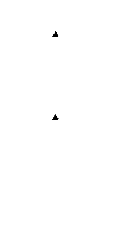
Typical System
Conduit (In Wall)
6 Valve
Soda
Tower
8 Valve
Soda
Tower
Water Booster
Air
Compressor
Conduit
CO
2
Panel
Multiplex
Refrigeration
Unit
CO
2
Tank
Bag-In-Box
(BIB)
Syrup
BIB
Rack
Water
Filters
BIB Pumps
Component Identification
Part Number STH12 9/10 43
Page 44

Connections
John Guest Fittings
Drain Hose
Control Switches
1/4" Plastic
CO
2
Line from
Carbonator
Right Hand
Opening for
Conduit Supply
Lines
MODEL 2803 CONNECTIONS
44 Part Number STH12 9/10
Page 45

MODEL 11M CONNECTIONS
John Guest Fittings
Drain Hose
Control Switches
Opening for
Conduit Supply
Lines
Part Number STH12 9/10 45
Page 46

MODEL 42, 44, & 50M CONNECTIONS
John Guest Fittings
Drain Hose
Control
Switches
(Non-ERC)
Opening for
Conduit Supply
Lines
ERC Controls
46 Part Number STH12 9/10
Page 47

ERC CONTROL BOARD OUTPUT CONNENCTIONS
CR
L
L/N
EARTH
AGITATIOR CIRC
CARB A CARB B CIRC A
PLUG THIS PIN
Part Number STH12 9/10 47
Page 48

ERC CONTROL BOARD INPUT CONNENCTIONS
HIGH PROBE
LOW PROBE
GND
GND
HIGH PROBE
LOW PROBE
HIGH PROBE
LOW PROBE
CO2 TS TD TW TB TA WL ICE CA A CA B
12 11 10 9 8 7 6 5 4 3 2 1
HPCO WATER
COM
+5V DC
OUTPUT
COM
+5V DC
GND
LEVEL PROBE
CIRC A TEMP
CIRC B TEMP
WATER BATH TEMP
DISCHARGE TEMP
SUCTION TEMP
OUTPUT
HPCO SWITCH
48 Part Number STH12 9/10
Page 49

Maintenance
Maintenance Schedule
This section provides a list of periodic maintenance
tasks and the scheduled frequency required to ensure
the proper operation of your Multiplex dispensing
equipment. To ensure quality beverages, prevent
downtime, and reduce costs, these tasks must be
performed as indicated.
PERIODIC MAINTENANCE FOR SOFT DRINK EQUIPMENT (LISTED BY MAJOR COMPONENTS)
Dispensing stations
Daily (365 times per year)
• Take te mperature of finished drinks. Pour off the
first and take the temperature of the second drink.
The proper temperature of drinks must be 38°F
(4°C) or less.
• Remove nozzles and diffusers from each
dispensing valve. Clean with soap and warm water
(not hot). Rinse with carbonated water and
reinstall.
• Flush all dispenser drains. Pour hot water down
drains at closing.
Beverage conduits
Every 4 months (3 times per year)
• Inspect beverage conduits for damage. Re-
insulate and seal any uninsulated areas.
• Inspect floor chases and seal any open chase
ends.
Air compressor
Monthly (12 times per year)
• Drain condensate water from air compressor tank.
Every 4 months (3 times per year)
• Inspect air compressor filter and repl ace if
clogged. Air filter must be replaced every 6
months.
Part Number STH12 9/10 49
Page 50

• Inspect air compressor to verify cut-in at 70 psi
(4.8 bar) and cut-out at 90 psi (6.3 bar). Adjust
pressure switch if necessary.
• Inspect system for air leaks and repair as required.
Refrigeration unit
Every 4 months (3 times per year)
• Clean the refrigeration unit air-cooled condenser
using a vacuum cleaner. If equipped with watercooled condenser, verify the water discharge
temperature is at 105°F (41°C). Adjust water
modulating valve if necessary.
• Inspect water bath to verify water level is at the top
of stand pipe. If below, add water and repair water
makeup device. If excessive amount of water is
flowing over stand pipe, locate leak within bath and
repair.
• Inspect ice bank within the water bath to verify
proper size ice bank and clarity. Look for uniform,
2" to 4" thick ice bank.
• Drain, clean, and refill water bath.
• Inspect agitator motor and ensure proper
operation.
• Inspect the circulating motor/pump assembly.
Clean strainer and oil motor.
• Inspect the carbonating motor/pump assembly.
Clean strainer and oil motor.
• Inspect entire system for leaks and repair as
required.
Water filters
Every 4 months (3 times per year)
• Verify that incoming water pressure is not less than
40 psi (2.8 bar) or greater than 60 psi (4.1 bar). If
equipped with a water regulator, verify proper
setting of 55 psi (3.8 bar). Adjust if necessary.
• If pressure is low, inspect water filter cartridges to
ensure they are able to supply adequate water
pressure under normal system flow. Replace if
unable to provide minimum 20 psi (1.4 bar) under
load.
50 Part Number STH12 9/10
Page 51

Syrup supply
Daily (365 times per year)
• Clean general area of syrup hookup with soap and
warm water. Rinse off all soap.
Every 4 months (3 times per year)
• Inspect syrup lines for proper flavor identification
labels. Replace labels if necessary.
• Disconnect syrup containers. Clean connector with
soap and warm water. Rinse with plain water and
reconnect to syrup containers.
CO2 gas supply
Every 4 months (3 times per year)
• Inspect pressure setting at CO
regulator. Verify proper 90 psi (6.3 bar) pressure
high pressure
2
setting. Adjust if necessary.
• Inspect pressure setting at syrup pressure
regulators. Verify propter pressure setting. Adjust if
necessary.
• Inspect system for CO
leaks, repair as required.
2
PERIODIC MAINTENANCE FOR SOFT DRINK EQUIPMENT (LISTED BY SCHEDULED FREQUENCY)
Daily (365 times per year)
• Take te mperature of finished drinks. Pour off the
first and take the temperature of the second drink.
The proper temperature of drinks must be 38°F
(4°C) or less.
• Remove nozzles and diffusers from each
dispensing valve. Clean with soap and warm water
(not hot). Rinse with carbonated water and
reinstall.
• Flush all dispenser drains. Pour hot water down
drains at closing.
• Clean general area of syrup hookup with soap and
warm water. Rinse off all soap.
Every 4 months (3 times per year)
• Using Brix cup and syrup separator, check for
proper carbonated water flows (standard flow: 5
oz. in 4 seconds, fast flow: 10 oz. in 4 seconds)
Part Number STH12 9/10 51
Page 52

and syrup to water ratios at each dispensing
station. Adjust as required.
• Inspect beverage conduits for damage. Reinsulate and seal any uninsulated areas.
• Inspect floor chases and seal any open chase
ends.
• Inspect air compressor filter and repl ace if
clogged. Air filter must be replaced every 6
months.
• Inspect air compressor to verify cut-in at 70 psi
(4.8 bar) and cut-out at 90 psi (6.3 bar). Adjust
pressure switch if necessary.
• Inspect system for air leaks and repair as required.
• Clean the refrigeration unit air-cooled condenser
using a vacuum cleaner. If equipped with watercooled condenser, verify the water discharge
temperature is at 105°F (41°C). Adjust water
modulating valve if necessary.
• Inspect water bath to verify water level is at the top
of stand pipe. If below, add water and repair water
makeup device. If excessive amount of water is
flowing over stand pipe, locate leak within bath and
repair.
• Inspect ice bank within the water bath to verify
proper size ice bank and clarity. Look for uniform,
2" to 4" thick ice bank.
• Drain, clean, and refill water bath.
• Inspect agitator motor and ensure proper
operation.
• Inspect the circulating motor/pump assembly.
Clean strainer and oil motor.
• Inspect the carbonating motor/pump assembly.
Clean strainer and oil motor.
• Inspect entire system for leaks and repair as
required.
• Verify that incoming water pressure is not less than
40 psi (2.8 bar) or greater than 60 psi (4.1 bar). If
equipped with a water regulator, verify proper
setting of 55 psi (3.8 bar). Adjust if necessary.
52 Part Number STH12 9/10
Page 53

• If pressure is low, inspect water filter cartridges to
ensure they are able to supply adequate water
pressure under normal system flow. Replace if
unable to provide minimum 40 psi (1.4 bar) under
load.
• Inspect syrup lines for proper flavor identification
labels. Replace labels if necessary.
• Disconnect syrup containers. Clean connector with
soap and warm water. Rinse with plain water and
reconnect to syrup containers.
• Inspect pressure setting at CO
regulator. Verify proper 90 psi (6.3 bar) pressure
high pressure
2
setting. Adjust if necessary.
• Inspect pressure setting at syrup pressure
regulators. Verify propter pressure setting. Adjust if
necessary.
• Inspect system for CO
leaks. Repair as required.
2
Part Number STH12 9/10 53
Page 54

Cleaning and Sanitizing the Dispensing Valves and Product Lines
MAINTENANCE SCHEDULE
Every day
Dispensing
valves
Drip pan and
drain hose
Quick
disconnects
Weekly
Outside,
dispenser
cabinet
Every 3 months
Syrup
circuits
Water bath Drain, melt ice and clean using
Every 6 months
Condenser Vacuum fins or use soft bristle brush
Air purifier
filter (if
equipped)
Remove nozzles and diffusers and
soak in mild detergent cleaning
solution. Scrub parts with small bristle
brush taking care to clean small
crevices and O-ring grooves. Turn
OFF power to dispensing valves.
Scrub exterior surfaces, including
bottom splash area and actuator
lever, with cleaning solution.
Reassemble diffusers and nozzles.
Wipe dry exterior surfaces before
turning ON power.
Wash with mild detergent. Rinse with
clean water.
Wash with mild detergent. Rinse with
potable water.
Wash with clean water and mild
detergent. Wipe dry.
Sanitize each syrup circuit. See
“Cleaning and Sanitizing Procedure”.
detergent and brush; rinse with
potable water. Do not use water over
140°F (60°C).
(scrub brush).
Replace.
54 Part Number STH12 9/10
Page 55

CLEANING EQUIPMENT AND SUPPLIES
• Recommended cleaner: Any caustic-base (low
sudsing, non-perfumed, easily rinsed) detergent
solution which provides a minimum 2% sodium
hydroxide. The solution must be prepared in
accordance with the manufacturer’s instructions.
Solution temperature must be between 90°F
(32°C) and 110°F (43°C). Temperatures in excess
of this can cause internal damage to the
dispensing valve components.
• Recommended sanitizer: Any sanitizer which
provides a minimum of 120 parts per million
(120 milligrams per liter) of available chlorine.
Solution temperature must be between 90°F
(32°C) and 110°F (43°C). Temperatures in excess
of this can cause internal damage to the
dispensing valve components.
• Two five gallon (figals) syrup tanks and fittings,
cleaned and sanitized (one for cleaner; one for
sanitizer)
• Containers for cleaner and sanitizer solutions
• Clean, non-abrasive cloths
• Buckets
• Small Brush
• Extra Nozzles
• Extra Jumpers
Part Number STH12 9/10 55
Page 56

CLEANING AND SANITIZING PROCEDURE
!
Caution
NOTE: Cleaning and sanitizing is not required for
potable water circuits. Potable water lines must remain
connected and operational during the cleaning and
sanitizing procedures for syrup circuits.
It is required that the Carbonated Water Lines
remain connected and operational during
cleaning and sanitizing of the syrup circuits.
Sanitizing of the valve without the Carbonated
Water side operation may leave bacteria in the
nozzle, diffuser, and syrup tube.
Cleaning and dispensing valves
1. Disconnect each syrup container from its product
line. Remove product from the lines by purging
with clean warm tap water until syrup has been
fully purged from the product lines and valves.
2. Clean all lines and fittings with cleaning solution
and rinse with clean, room temperature water to
remove all traces of residual product.
Cleaning the product lines
1. To clean each valve product line, attach the valve
product lines to the pressure tank containing the
cleaning solution. Make sure each line is
completely filled. Pressurize the lines by pulsing
the valves.
Pressurizing the product lines
A. For 15 seconds turn dispensing valve ON,
OFF, and then immediately ON again for 15
cycles.
B. Allow the valve to remain flowing for 3
minutes.
C. Repeat pulsing and flowing the valves again
until all cleaning solution has been used.
56 Part Number STH12 9/10
Page 57

!
Caution
Do not allow cleaning and sanitizing solutions to
remain in syrup systems longer than
recommended contact time. Exceeding contact
time will result in damage to valve components.
2. Flush the cleaning solution from the lines with
clean water after a minimum of 3 minutes, by
pulsing the valves as described above.
3. Remove the nozzles and the diffuser assemblies
from the valves. Clean with cleaning solution.
Agitate the assemblies to ensure assemblies are
clean. Place them in a container of sanitizing
solution for 15 minutes. Wearing sanitary gloves,
remove the nozzles and diffuser assemblies from
the sanitizing solution. Drain each until dry and
reassemble to the valves.
4. Attach each valve product line to the pressure
tank containing the sanitizing solution. Be sure all
connections are cleaned and sanitized before
connecting to each product line.
5. Pressurize and fill the lines with sanitizing
solution. Make sure lines are completely filled,
Allow the sanitizing solution to flow through each
valve while activating the valves for 15 cycles.
A. Leave valves OFF and allow to stand
pressurized for 30 minutes.
B. Activate the valves for two (2) cycles. Flush
remaining sanitizer continuously through the
valves.
6. Reconnect the syrup containers to their
respective circuits. Prepare the unit for operation.
7. Draw drinks to refill lin es and flush the sanitizing
solution from the dispenser. Taste the beverage to
verify that there is no off-taste (chlorine).
Part Number STH12 9/10 57
Page 58

Sanitizing
! Warning
! Warning
BEVERAGE SYSTEM CLEANING
Flush sanitizing solution from syrup system.
Residual sanitizing solution left in system could
create a health hazard.
When using cleaning fluids or chemicals, rubber
gloves and eye protection must be worn.
Sanitize the beverage system at initial start-up as well
as regularly scheduled cleaning. The drain pan must
be in place under soda valves, to carry away detergent
and sanitizing agents that will be flushed through
valves.
BAG-IN-BOX SYSTEM SANITATION
The procedure below is for the sanitation of one
syrup circuit at a time. Repeat to sanitize
additional circuits.
You will need the following items to clean and sanitize
the Bag-in-Box (BIB) beverage system:
• Three (3) clean buckets
• Plastic brush or soft cloth
• Mild detergent
• Unscented bleach (5% Na CL O) or
Commercial sanitizer
• Bag-In-Box bag connector
1. Prepare the following in the buckets:
• Bucket 1 — warm to hot tap water for rinsing.
• Bucket 2 — mild detergent and warm to hot
water.
58 Part Number STH12 9/10
Page 59

• Bucket 3 — mix a solution of unscented
Bag
side
connector
bleach (5% Na CL O) or commercial sanitizer
and warm to hot water. Mixture should supply
100 PPM available chlorine (1/4 oz. bleach to
1 gallon water).
2. Disconnect the “syrup-line side” of the BIB
connector.
3. Rinse connector with warm tap water.
Part Number STH12 9/10 59
Page 60

4. Connect syrup connector to BIB connector and
immerse both into Bucket 1. A “bag-side”
connector can be created by cutting the connector
from an empty disposable syrup bag.
5. Draw rinse water through system until clean water
is dispensed. Most beverage valves allow the
syrup side to be manually activated by depressing
the syrup pallet.
6. Connect Bucket 2 to system.
7. Draw detergent solution through system until
solution is dispensed.
8. Repeat steps 2-7 until all syrup circuits contain
detergent solution.
9. Allow detergent solution to remain in the system
for 5 minutes.
10. Connect Bucket 3 to system.
11. Draw sanitizing solution through system until
solution is dispensed.
12. Repeat step 11 until all syrup circuits contain
sanitizer solution.
13. Allow sanitizer solution to remain in system for 15
minutes.
14. Remove nozzles and di ffusers from beverage
valves.
15. Scrub nozzles, diffusers and all removable valve
parts (except electrical parts) with a plastic brush
or a soft cloth and the detergent solution.
16. Soak nozzles, diffusers and removable valve
parts (except electrical parts) in sanitizer for 15
minutes.
17. Replace nozzles, diffusers and valve parts.
18. Connect Bucket 1 to system.
19. Draw rinse water throug h system until no
presence of sanitizer is detected.
20. Attach syrup connectors to BIBs.
21. Draw syrup through system until only syrup is
dispensed.
22. Discard first 2 drinks.
60 Part Number STH12 9/10
Page 61

FIGAL BEVERAGE SYSTEM
1. Prepare the following in three clean Figal tanks:
• Rinse tank - fill with room temperature tap
water.
• Detergent tank - mix approved beverage
system cleaner with warm water as directed.
• Sanitizing tank - mix a solution of un sce nted
bleach (5% Na CL O) or commercial sanitizer
and warm to hot water. Mixture should supply
100 PPM available chlorine (1/4 oz. bleach to
1 gallon water).
2. Disconnect all product and water lines from
product tanks and remove carbonator.
3. Locate the Figal syrup tank for the circuit to be
sanitized. Remove both quick disconnects from
the Figal syrup tank. Rinse quick disconnects in
tap water.
4. Connect rinse tank to the syrup line. Draw clean
rinse water through the valve until syrup is flushed
from the system.
5. Connect detergent tank to the syrup line and draw
detergent through the valve for two minutes.
Then, allow remaining detergent to stay in the
system for five minutes.
6. Connect rinse tank to the syrup line. Draw clean
rinse water through the valve until detergent is
flushed from the system.
7. Remove valve nozzle and diffuser as shown in
Daily Cleaning instructions. Using a plastic brush
or a soft cloth and warm water, scrub the nozzle,
diffuser, bottom of the dispensing valve and cup
lever, if applicable.
8. Place removable valve parts (EXCEPT solenoids)
in sanitizing solution for 15 minutes.
9. Replace valve diffuser and nozzle on the
beverage valve.
10. Connect sanitizer tank to the syrup line and draw
sanitizer through the valve for two minutes. Allow
sanitizer to remain in the system for a minimum of
15 minutes.
Part Number STH12 9/10 61
Page 62

11. Reconnect syrup and carbonated water lines.
!
Caution
12. Draw syrup through the lines to rinse the system.
Discard drinks until at least two cups of
satisfactory tasting beverage are dispensed
through the valve.
Shipping, Storage and Relocation
Before shipping, storing, or relocating this unit,
syrup systems must be sanitized. After sanitizing,
all liquids (sanitizing solution and water) must be
purged from the unit. A freezing environment
causes residual sanitizing solution or water
remaining inside the unit to freeze, resulting in
damage to internal components.
62 Part Number STH12 9/10
Page 63

Operation
How the Multiplex Works
Model 2803 — a 1/3 HP refrigeration unit that will provide
pre-mix carbonated beverages and chilled carbonated water
for up to 6 gal (3 L) of syrup/day or 280 drinks/day (2,000 gal/yr)
with a 40 ft (12 m) maximum conduit length. This is a remote
refrigeration unit that derives its peak draw capacity from the
reserve ice bank produced from a capillary tube refrigeration
system. This system is controlled to cycle ON and OFF by the
operation of the ice bank control. The sensing bulb that controls
the ice bank is located on an adjustable bracket in the water
bath.
Model 11M — a 1/2 HP refrigeration unit that will provide
premix carbonated beverages and chilled carbonated water for
up to 12 gal (45 L) of syrup/day or 560 drinks/day (4,000
gal/year) with a 100 ft (30 m) maximum conduit length. This is
a remote refrigeration unit that derives its peak draw capacity
from the reserve ice bank produced from a capillary tube
refrigeration system. This system is controlled to cycle ON and
OFF by the operation of the ice bank control. The sensing bulb
that controls the ice bank is located on an adjustable bracket in
the water bath.
Model 42M — a 1 HP refrigeration unit that will provi de pre-mix
carbonated beverages and chilled carbonated water for up to
50 gal (190 L) of syrup/day or 3,060 drinks/day (18,200 gal/yr)
with a 250 ft (80 m) maximum conduit length. This refrigeration
unit is a remote refrigeration unit that derives its peak capacity
from the reserve ice bank produced from a TXV system. This
system is controlled to cycle ON and OFF by the operation of
the ice control. The sensing probe that controls the ice bank, is
located on an adjustable bracket in the water bath.
Model 44M — a 1 HP refrigeration unit that will provi de pre-mix
carbonated beverages and chilled carbonated water for up to
50 gal (190 L) of syrup/day or 3,060 drinks/day (18,200 gal/yr)
with a 250 ft (80 m) maximum conduit length. This refrigeration
unit is a remote refrigeration unit that derives its peak capacity
from the reserve ice bank produced from a TXV system. This
system is controlled to cycle ON and OFF by the operation of
the ice control. The sensing probe that controls the ice bank, is
located on an adjustable bracket in the water bath.
Part Number STH12 9/10 63
Page 64

Model 50M — a 2.2 HP Pre-mix refrigeration unit that will
• The TS uses common components from Manitowoc Ice makers
to assist in product and parts availability.
provide pre-mix carbonated beverages and chilled carbonated
water for up to 42 gal (159 L) of syrup/day or 2,000 drinks/day
(15,000 gal/yr) with a 350 ft (107 m) maximum conduit length.
This refrigeration unit is a remote refrigeration unit that derives
its peak capacity from the reserve ice bank produced by the
operation of the compressor. This system is controlled to cycle
ON and OFF by the operation of the ice bank control. The
sensing bulb that controls the ice bank is located on an
adjustable bracket in the water bath.
Differences Between the TS & SS Units
Multiplex soda and water chillers may have three
different series numbers. Starting in 2007 some no
longer begin with an “SS”; they now begin with a “TS”.
Starting in 2008, units with ERC (Electronic
Refrigeration Controls) end with an “E”. The following
shows you how to tell the difference between the TS
version and the SS.
64 Part Number STH12 9/10
Page 65

• The TS compressor is mounted with bolts instead of studs.
• TS remote and water-cooled back panel connections
are offset to protect fittings.
Part Number STH12 9/10 65
Page 66

WATER MANIFOLD TS
• TS air-cooled condenser comes standard with a filter.
Two Stainless Steel log style
manifolds
• One regulated supply for
carbonator pumps.
• One unregulated supply for
non-carb drinks and water
bath fill.
Other Connections
• Connections are made in the
water bath compartment.
• Separate plain water manifold
eliminates need to plug off
during installation.
66 Part Number STH12 9/10
Page 67

ELECTRICAL TS
• Electrical compartment has been moved up on the unit to eliminate
water intrusion potential from the pump compartment.
• All components are now 208/230V. This eliminates the need for a
neutral wire.
• New unit has service connections in the electrical compartment.
Allows more room to work and more reliable connection.
• Pump protection switch has been moved to the pump
compartment to eliminate potential leak point in electrical
compartment.
Part Number STH12 9/10 67
Page 68

WATER BATH ACCESS SS
• Has a round hole in the front and back panels with
no edge trim to protect lines.
• End panel has two ovals in the rear of the panel with
edge trim to help protect conduit lines.
• All panels have large oval access holes with interchangeable
covers.
• Front panel has 3 hole cover for water and CO
2
line routing.
• Back panel has solid cover.
• End panel has one open cover and one solid cover.
• Open cover provides wide ledge for conduit line protection.
WATER BATH ACCESS TS
68 Part Number STH12 9/10
Page 69

SERVICE ACCESS SS
• Front panel was solid and did not allow easy access for service.
• Switch panel was mounted flush to end panel.
SERVICE ACCESS TS
• Front panel is split to allow front access to the compressor
compartment.
• Switches are recessed and the edge has trim panel to protect
fingers from sheet metal edges.
Part Number STH12 9/10 69
Page 70

SERVICE ACCESS TS WITH ERC
LED Display
Service Switch
Program
Switch
SER
PGM
CIRC
B
COMP/
AGIT
CARB A CARB B CIRC A CIRC B
• Service Switch — (SER) switch, press to send ID on power line
network.
• Wink Function — LED flashes “Ion” to indicate wink function. Press
program switch (PGM) to disable wink function.
70 Part Number STH12 9/10
Page 71

Equipment Setup Procedure (Non-ERC)
1. Ensure that all valve nozzles are attached to the
valves.
2. Observe pressure of CO2 high pressure tank of
500 psi (34 bar) or more, or bulk CO
150 psi or more. Primary regulator set at 90 psi
(6 bar) and the secondary regulator set at 35 psi
(2.4 bar).
3. Observe the contro l panel to verify that al l
pressure gauges are set at correct operating
pressures.
4. Check the syrup tanks to make sure a sufficient
number of tanks are connected in series to satisfy
business volume.
5. Clean syrup inlet and outlet quick disconnects at
the same time tanks are replaced. Rinse
disconnects in clean potable water.
tank of
2
Part Number STH12 9/10 71
Page 72

Start-up (Non-ERC)
1. Fill the refrigeration unit water bath tank with
water to within 1/2" (1.27 cm) of the top of the
overflow tube.
2. Open the manual water shut-off valve to the water
cooled condenser (if applicable).
3. Turn ON the rocker switch labeled “Refrigeration”
to begin building an ice bank.
4. Turn ON the rocker switch labeled “Agitator”.
NOTE: On TS units 3 & 4 are combined into 1 switch.
5. Ice will begin to form on the evaporator coils in
approximately 2 hours.
6. The refrigeration unit will build an ice bank in
approximately 4 to 6 hours.
7. If optional CO
installed on the refrigeration unit, refer to the
installation instructions for operation and testing
the circuits for leaks.
8. The carbona tion circuits “A” and “B,” as well as
the syrup circuits must be checked for leaks and
possible cross circuits before turning ON the
water supply to carbonator pumps.
9. Turn on main water supply. Set incoming
regulator to 55 psi on the CO
Model 11M root beer system’s internal regulator
(must be lower than CO2 supply pressure). Once
water is supplied to the unit, air needs to be
purged from the carbonator tank. Do so by lifting
press relief valve tab until water comes out of
relief valve.
10. Turn on main CO
90 – 100 psi. For the Model 11 Root Beer system,
set regulator initially to 26 psi; it can be raised
incrementally to 30 psi if there is excessive
foaming.
11. Set bag-in-box syrup tank push pressure CO
regulator to 65 – 70 psi. For the Model 11 Root
Beer system, set push pressure CO
35 – 40 psi.
/Water Control Panel has been
2
panel; 25 psi for the
2
supply. Set regulator initially to
2
regulator to
2
2
72 Part Number STH12 9/10
Page 73

PLACING THE CARBONATION SYSTEM IN OPERATION
1. Open the CO
bulk tank. Adjust the CO
(6.2 bar).
gas supply valve at CO2 tanks or
2
pressure to 90 psi
2
2. Open relief valve on top of the carbonator tank for
4 seconds to bleed off air in tank.
3. Turn ON the water supply to unit.
4. Turn ON the switch labeled “Carbonator Pump”.
Allow carbonator to run and cycle OFF.
5. Activate all valves until a smooth, continuous flow
of carbonated water and non-carbonated water
appear at the valves.
6. Turn ON switch labeled “Circulator”.
7. Allow at least 1 hou r before proceeding to
calibration instructions. You may complete the
sanitizing instructions during this period.
Part Number STH12 9/10 73
Page 74

Sequence of Operation (Non-ERC)
PRE-MIX REFRIGERATION UNIT
Ice Bank Is Required
1. Check water bath for full ice bank.
2. The stabilized water bath operating temperature
must be maintained at 33°F (0.6°C) to 35°F
(1.7°C).
The following is a sequence of operations for the
Multiplex Pre-mix Beverage equipment.
1. Once a drink is dispensed, the following will
occur:
A. For a Syrup Tank System, the Pre-mix syrup
is manually mixed at the store. Pre-mix
beverage is then transferred to a holding tank
for supply to the Multiplex system.
B. For a Bag-In-Box System, pre-mix syrup is
drawn from a Bag-In-Box by means of a gas
driven syrup pump.
2. The carbonator pump (stainless) pulls the 5:1
pre-mix out of the 3 gallon holding tank and injects
it into the pre-mix carbonator tank where the CO
pressure is 35 psi (2.4 bar) on the tank.
3. The circulator pump runs continuously and
circulates water bath water through the conduit to
provide cooling for all drinks.
2
74 Part Number STH12 9/10
Page 75

Multiplex Pre-mix Beverage System Operation
Conduit (In Wall)
6 Valve
Soda
Tower
8 Valve
Soda
Tower
Water Booster
Air
Compressor
Conduit
CO
2
Panel
Multiplex
Refrigeration
Unit
CO
2
Tank
Bag-In-Box
(BIB)
Syrup
BIB
Rack
Water
Filters
BIB Pumps
Part Number STH12 9/10 75
and Layout
Page 76

Start-up (with ERC)
PLACING EQUIPMENT IN OPERATION
Before placing equipment in operation, verify that all
requirements for roof mounted Remote Condenser
Units (if applicable) have been satisfied. Refer to the
instructions on installing the Remote Condenser.
Verify proper supply power to unit.
1. Fill the refrigeration unit water bath tank with
water to within 1/2" (1.27 cm) of the top of the
overflow tube.
2. Open the manual water shut-off valve to the water
cooled condenser (if applicable). Refer to
“Electronic Control” for control programming
sequence.
3. Press “Comp/Agit” to begin building an ice bank.
4. Ice will begin to form on the evaporator coils in
approximately 2 hours.
5. The refrigeration unit will build an ice bank in
approximately 4 to 6 hours.
6. If optional CO
installed on the refrigeration unit, refer to the
installation instructions for operation and testing
the circuits for leaks.
7. The carbona tion circuits “A” and “B,” as well as
the syrup circuits must be checked for leaks and
possible cross circuits before turning ON the
water supply to carbonator pumps.
8. Turn on main water supply. Set incoming
regulator to 55 psi on the CO
panel. Once water is supplied to the unit, air
needs to be purged from the carbonator tank. Do
so by lifting press relief valve tab until water
comes out of relief valve.
9. Set bag-in-box syrup tank push pressure CO
regulator to 60 psi.
/Water Control Panel has been
2
/Water control
2
2
76 Part Number STH12 9/10
Page 77

PLACING THE SYRUP SYSTEM IN OPERATION
1. Open the CO
bulk tank. Adjust the CO
(6.2 bar).
gas supply valve at CO2 tanks or
2
pressure to 90 psi
2
2. Open relief valve on top of the carbonator tank for
4 seconds to bleed off air in tank.
3. Verify the water supply to unit is on.
4. Press the switch labeled “Carb A” (and B if
applicable). Allow carbonator to run and cycle
OFF.
5. Press the switch labeled “CIRC A” (and “CIRC B”
if applicable).
6. Activate all vales un til a smooth, continuous flow
or carbonated water and non-carbonated water
appear at the valves.
7. Allow at least 1 hou r before proceeding to
calibration instructions. You may complete the
sanitizing instructions during this period.
Part Number STH12 9/10 77
Page 78

Sequence of Operation (with ERC)
ELECTRONIC CONTROL
Prerequisites
• Potable water must be connected to the
carbonator pump circuit.
• The ice bank water bath water must cover the
evaporator. The compressor will not start unless
the ice bank control probes are immersed in water.
•CO
Initial Power-up
The control has a 30-second delay when power is
connected, or disconnected and reconnected. The
display will show Pd30 - power delay and 30 seconds
left in the countdown cycle.
Normal Two Circuit Operation
Pressing the COMP/AGIT button will start the water
bath agitator immediately and initiate the 180 second
compressor delay. The display will show Cd99
(compressor delay & 99 seconds) and will start to
count down from 99 seconds after the first 81 seconds
have elapsed. After 180 seconds the compressor and
condenser fan motor energize and the COMP/AGIT
LED flashes. Pressing the CARB A and CARB B
buttons will power the carbonator tank liquid level
control. The corresponding LED flashes to indicate the
pump is running. Pressing the CIRC A & CIRC B
buttons will immediately energize the circulating
pumps and energize the LED constantly. The display
will show the circulating temperature and show the A
circuit. When two circuits are used the readout will
alternate between A and B circuits every 5 seconds.
The compressor and condenser fan will continue to
run until ice contacts the ice bank control probe closest
to the evaporator. When ice contacts the probe, the
COMP/AGIT LED lights constantly and the
compressor and condenser fan motor de-energize.
As the ice bank melts, the ice bank control probe will
lose contact with the ice; the LED will flash and the
compressor and condenser fan motor will restart. This
cycle will repeat as required depending on load.
must be supplied.
2
78 Part Number STH12 9/10
Page 79

Power Interruption
SER
PGM
CIRC
B
CIRC
A
COMP/
AGIT
CARB
A
CARB
B
CIRC
A
CIRC
B
During a power interruption the control will resume
from the point of interruption when power is reapplied
and the time delay expires. Any switches/components
that were energized when power was interrupted will
be energized when power is reapplied.
Error Codes
E1 = Low Water Supply Pressure
E2 = Low CO
Pressure
2
E3 = Low Water Level - Water Bath
E4 = High Water Bath Temperature
E5 = High Water Supply Pressure
E6 = High Refrigeration Temperature
E7 = High Ice Bank Size (Probe Sensor 2)
E8 = Long Carb A Run Time
E9 = Long Carb B Run Time
NOTE: Shorted Transducer = "----"
Open Transducer = "===="
Error codes will display until corrected.
Control Programming
SER Switch
• For when optional LON communication network is
connected.
Part Number STH12 9/10 79
Page 80

PGM Switch
• Used to enter and exit programming modes.
• Press PGM Switch F000 will display
• Press and hold Carb A switch — Display will
indicate Water Bath Temperature
• Press and hold Circ A switch — Display will
indicate Discharge Temperature
• Press and hold Circ B switch — Display will
indicate Suction Temperature
• Press PGM Switch P000 will display
• Press and hold Carb A switch — Display will
indicate Water Pressure
• Press and hold Carb B switch — Display will
indicate CO2 Pressure
Press and hold PGM switch for 3 seconds to save
settings and exit program mode.
Program Mode 1
To enter, press and hold switch for 3 seconds.
• 0001 will display indicating Mode 1
• Wait 3 seconds — C000 will display
• Press and hold Carb A switch — Display will
indicate one of the following:
• CA00 — Low and High Probes are open
(carbonator motor is energized)
• CA11 — Low and High Probes are closed
(carbonator motor is de-energized)
• CA01 — Low Probe closed (Motor will still be
on)
80 Part Number STH12 9/10
Page 81

• Press and hold Carb B switch — Display will
indicate one of the following:
• Cb00 — Low and High Probes are open
(carbonator motor is energized)
• Cb11 — Low and High Probes are closed
(carbonator motor is de-energized)
• Cb01 — Low Probe closed (Motor will still be
on)
• Press and hold COMP/AGIT switch — Display will
indicate one of the following:
• CL 0 — Water level low
• CL 1
— Water level OK
Program Mode 2
Add circulation pumps C & D.
• Press PGM button for 3 seconds — Display shows
0001.
• Press PGM button — Display shows 0002
program mode 2.
• Wait 3 seconds — Display shows -002 = Factory
default setting.
• Pressing CIRC A button
energizes/de-energizes pump A
• Pressing CIRC B button
energizes/de-energizes pump B
• Program CIRC C — Press CARB A button –
Display shows -102 = Carb A button
energizes/de-energizes pump C
• Program CIRC D — Press CARB B button Display shows -012 = Carb B button
energizes/de-energizes pump D
Press and hold PGM switch for 3 seconds to save
settings and exit program mode.
Part Number STH12 9/10 81
Page 82

Program Mode 4
Temporarily cancel display of error codes. Cancelling
the error codes allows circulating glycol temperatures
to be displayed until the error can be corrected.
• Press PGM button for 3 seconds — Display shows
0001.
• Press PGM button three times — Display shows
0004 program mode 4.
• Wait 3 seconds — Display shows -004 = All error
codes will be displayed during run mode.
• Press COMP/AGIT button once — Display shows
---4 = error codes will not be displayed during run
mode.
NOTE: Disconnecting and reconnecting main power
will reset the control board to the factory setting -004 =
Error codes will be displayed in the run mode.
Equipment Setup Procedure (with ERC)
1. Ensure that all valve nozzles are attached to the
valves.
2. Observe pressure of CO
500 psi (34 bar) or more, or bulk CO
150 psi or more. Primary regulator set at 90 psi
(6 bar) and the secondary regulator set at 35 psi
(2.4 bar).
3. Observe the control panel to verify that all
pressure gauges are set at correct operating
pressures.
4. Check the syrup tanks or BIB to make sure a
sufficient number of tanks are connected in series
to satisfy business volume.
5. Clean syrup inlet and outlet quick disconnects at
the same time tanks are replaced. Rinse
disconnects in clean potable water.
high pressure tank of
2
tank of
2
82 Part Number STH12 9/10
Page 83

Multiplex Electronic Refrigeration Control (ERC)
SUPPLY POWER ON
AGITATOR
COMES ON
CONSTANTLY
COMPRESSOR
DELAY SHOWS
“Cd99” AND
COUNTS DOWN
TO “Cd00”
POWER UP DELAY
SHOWS “Pd30”
AND COUNTS
DOWN TO “Pd00”
COMPRESSOR
COMES ON AFTER
DELAY, IF
CONTROL CIRCUIT
REQUIRES
COMP/AGIT
SWITCH ON
YES
NO
YES
NO
ERROR
CODE(S)
NORMAL RUN
MODE DISPLAY
SHOWS CIRC
WATER TEMP (S)
OR WATER BA TH
TEMP IN BEER
PRESS ANY
SWITCH TO
TURN ON LOAD
OR LOAD
CONTROL
CIRCUIT
RESPECTIVE
LED COMES ON
CONSTANT,
FLASHES IF
LOAD CONTROL
CIRCUIT ON
ERROR CODE
DISPLAYS TILL
CORRECTED
MULTIPLE
ERRORS CYCLE
PGM MODE 4
OVERRIDES
E1 = LOW WATER PRESS
E2 = LOW CO2 PRESS
E3 = LOW WATER BATH LEVEL
E4 = HIGH WATER BATH TEMP
E5 = HIGH WATER PRESS
E6 = HIGH REFRIGERATION TEMP
E7 = LARGE ICE BANK
E8 = LONG CARB A RUN TIME
E9 = LONG CARB B RUN TIME
“===” =OPEN
“___” =SHORT
ENTER PROGRAM MODE
EXIT PROGRAM MODE
PROGRAM MODE
TO ENTER, PRESS AND HOLD PGM SWITCH FOR MINIMUM OF 3 SECONDS. DISPLAY SHOWS “0001”
TO EXIT, PRESS AND HOLD PGM SWITCH FOR MINIMUM OF 3 SECONDS. DISPLAY SHOWS NORMAL RUN MODE
PROGRAM MODE 1 PROGRAM MODE 2
PROGRAM MODE 3 PROGRAM MODE 4
Programming
Part Number STH12 9/10 83
Page 84

PROGRAM MODE 1
READ CONDUCTIVITY,
TEMPERATURE,
PRESSURE CHANGE
UNITS
WAIT 3 SECONDS
DISPLAY SHOWS “C000”
PROGRAM MODE 2
PROGRAM ONE OR TWO MORE
CIRCULATING PUMPS
PRESS PGM SWITCH ONCE IN
LESS THAN 3 SECONDS
DISPLAY “0002”, WAIT THREE
SECONDS DISPLAY “-002”
PROGRAM MODE 3
PROGRAM TEMPERATURE
CONTROL OF WATER BATH
(BEER)
PRESS PGM SWITCH TWICE
IN LESS THAN 3 SECONDS,
DISPLAY “0003”, WAIT
THREE SECONDS DISPLAY
“-003”
PROGRAM MODE 4
TEMPORARILY DISABLE
ERRORS
PRESS PGM SWITCH
THREE TIMES IN LESS
THAN THREE SECONDS
DISPLAY “0004”, WAIT
THREE SECONDS
DISPLAY “-004”
PRESS COMP/AGIT
SWITCH, DISPLAY
SHOWS “---4”
INDICATING ERROR
CODES WILL BE
DISABLED UNTIL NEXT
POWER ON/OFF
SEQUENCE
TO CHANGE UNITS
WHEN “F000” PRESS
COMP/AGIT SWITCH
ONCE TO CHANGE
TEMPERATURE UNITS
TO CENTIGRADE
“FC00”
WHEN “P000” PRESS
COMP/AGIT SWITCH
ONCE TO CHANGE
PRESSURE UNITS TO
BAR “Fb00”
PRESS COMP/AGIT SWITCH
ONCE, DISPLAY = “1XX3” WHERE
XX=SET POINT TEMPERATURE
(DEFAULT = “1273”)
(DIFFERENTIAL FIXED AT 2°
ABOVE SET POINT)
PRESS CIRC A SWITCH
TO LOWER SET POINT
TEMPERATURE
PRESS CIRC B SWITCH
TO RAISE SET POINT
TEMPERATURE
NOTE:
SET POINT =
COMPRESSOR OFF
DIFFERENTIAL IS FIXED
AT 2°F ABOVE SET POINT
COMPRESSOR ON
PRESS CARB A SWITCH TO
CONVERT CARB A MOTOR
TO CIRC MOTOR
“-102”
PRESS CARB B SWITCH TO
CONVERT CARB B MOTOR
TO CIRC MOTOR
“-112”
“F0000” (TEMPERATURE)
PRESS CARB A SWITCH
TO SHOW WATER BATH
TEMP
PRESS CIRC A SWITCH TO
SHOW DISCHARGE TEMP
PRESS CIRC B SWITCH TO
SHOW SUCTION TEMP
PRESS PGM SWITCH ONCE
“P000” (PRESSURE)
PRESS CARB A SWITCH
TO SHOW WATER SUPPL Y
PRESSURE
PRESS CARB B SWITCH
TO SHOW CO2 PRESSURE
“C000” (CONDUCTIVITY)
PRESS COMP/AGIT
SWITCH TO SHOW ICE
BANK PROBE
“CC11” = NO ICE
COMPRESSOR ON; “CC10”
= ICE ON LOW SENSOR
COMPRESSOR OFF
“CC00” = ICE BANK TOO
LARGE (E7)
PRESS CARB A SWITCH
TO SHOW LLC PROBE
“CA00” = NO WATER
CARB A MOTOR ON
“CA01” = LOW SENSOR
IN WATER, MOTOR ON
“CA11” = LOW & HIGH
SENSOR IN WATER,
MOTOR OFF
REPEAT ABOVE FOR
CARB B SWITCH “CbXX”
PRESS CIRC A SWITCH
TO SHOW WATER LEVEL
PROBE “CL 1” = WATER
“CL 0” = LOW WATER (E3)
PRESS PGM SWITCH ONCE
Equipment Close Procedure — All Units
1. Clean the unde rside of the dispensing tower
around the nozzle area with a clean damp towel.
2. Pour at least 60 oz (1.8 liters) of warm water down
the drain openings.
84 Part Number STH12 9/10
Page 85

MUL TIP LEX ELECTRONIC REFRIGERATION
POWER UP DELAY
SHOWS “Pd30”
AND COUNTS
DOWN TO “Pd00"
SUPPLY POWER ON
NORMAL RUN
MODE
DISPLAY SHOWS
CIRC WATER
TEMP(S) OR
WATER BATH
TEMP IN BEER
MODE
COMP/AGIT
SWITCH ON
NO
YES
P R O G R A M M O D E
TO ENTER, PRESS AND HOLD PGM SWITCH FOR MINIMUM OF 3 SECONDS, DISPLAY SHOWS “0001”
TO CHANGE TO NEXT PROGRAM MODE, PRESS PGM BUTTON SEQUENTIALLY IN LESS THAN 3 SECONDS FROM ENTER (“0002”, ETC)
TO EXIT, PRESS AND HOLD PGM SWITCH FOR MINIMUM OF 3 SECONDS, DISPLAY SHOWS NORMAL RUN MODE
RESPECTIVE
LED COMES ON
CONSTANT,
FLASHES IF
LOAD CONTROL
CIRCUIT ON
PRESS ANY
SWITCH TO
TURN ON LOAD
OR LOAD
CONTROL
CIRCUIT
AGITATOR
COMES ON
CONSTANTLY
COMPRESSOR
COMES ON AFTER
DELAY, IF
CONTROL CIRCUIT
REQUIRES
ENTER PROGRAM MODE
EXIT PROGRAM MODE
PROGRAM MODE 4
TEMPORARILY DISABLE
ERRORS
PRESS PGM SWITCH
THREE TIMES (3) IN
LESS THAN 3 SECONDS
DISPLAY “0004”, WAIT
THREE (3) SECONDS
DISPLAY “-004”
PROGRAM MODE 3
PROGRAM TEMPERATURE
CONTROL OF WATER BATH
(BEER)
PRESS PGM SWITCH TWICE
(2) IN LESS THAN 3
SECONDS, DISPLAY “0003”,
WAIT THREE (3) SECONDS
DISPLAY “-003”
PROGRAM MODE 2
PROGRAM ONE (1) OR TWO (2)
MORE CIRCULATING PUMPS
PRESS PGM SWITCH ONCE (1)
IN LESS THAN 3 SECONDS
DISPLAY “0002”, WAIT THREE
(3) SECONDS DISPLAY “-002”
PROGRAM MODE 1
READ CONDUCTIVITY,
TEMPERATURE,
PRESSURE
CHANGE UNITS
WAIT 3 SECONDS
DISPLAY SHOWS “C000”
COMPRESSOR
DELAY SHOWS
“Cd99” AND
COUNTS DOWN
TO “Cd00”
ERROR
CODE(S)
NO
YES
ERROR CODE
DISPLAYS TILL
CORRECTED
MULTIPLE
ERRORS CYCLE
PGM MODE 4
OVERRIDES
E1 = Low Water Suply Pressure
E2 = Low Co2 Pressure
E3 = Low Water Level - Water Bath
E4 = High Water Bath Temperature
E5 = High Water Supply Pressure
E6 = High Refrigeration Temperature
E7 = High Ice Bank Size (Probe Sensor 2)
E8 = Long Carb A Run Time
E9 = Long Carb B Run Time
Shorted Transducer = "----"
Open Transducer = "===="
CONTROL (ERC) PROGRAMMING
Part Number STH12 9/10 85
Page 86

“C000”(CONDUCTIVITY)
PRESS COMP/AGIT
SWITCH TO SHOW ICE
BANK PROBE
“CC11” = NO ICE
COMPRESSOR ON
“CC10”= ICE ON LOW
SENSOR COMPRESSOR
OFF
“CC00” = ICE BANK TOO
LARGE (E7)
PRESS CARB A SWITCH
TO SHOW LLC PROBE
“CA00” = NO WATER
CARB A MOTOR ON
“CA01”= LOW SENSOR
IN WATER, MOTOR ON
“CA11” = LOW & HIGH
SENSOR IN WATER,
MOTOR OFF
REPEAT ABOVE FOR
CARB B SWITCH “CbXX”
PRES CIRC A SWITCH
TO SHOW WATER
LEVEL PROBE
“CL_1” = WATER
“CL_0” = LOW WATER
(E3)
PRESS COMP/AGIT
SWITCH, DISPLAY
SHOWS “---4”
INDICATING ERROR
CODES WILL BE
DISABLED UNTIL
NEXT POWER OFF/ON
SEQUENCE
“F000” (TEMPERATURE)
PRESS CARB A SWITCH
TO SHOW WATER BATH
TEMP
PRESS CIRC A SWITCH
TO SHOW
LIQUID LINE TEMP
PRESS CIRC B SWITCH
TO SHOW
SUCTION TEMP
“P000” (PRESSURE)
PRESS CARB A SWITCH
TO SHOW WATER
SUPPLY PRESSURE
PRESS CARB B
SWITCH TO SHOW CO2
PRESSURE
PRESS COMP/AGIT
SWITCH ONCE, DISPLAY
=”1XX3" WHERE XX= SET
POINT TEMPERATURE
(DEFAULT = “1273”)
(DIFFERENTIAL FIXED AT
2° ABOVE SET POINT)
PRESS CIRC A SWITCH
TO LOWER SET POINT
TEMPERATURE
PRESS CIRC B SWITCH
TO RAISE SET POINT
TEMPERATURE
NOTE:
SET POINT =
COMPRESSOR OFF
DIFFERENTIAL IS FIXED
AT 2°F ABOVE SET POINT
COMPRESSOR ON
PRESS CARB A SWITCH TO
CONVERT CARB A MOTOR
TO CIRC MOTOR
“-102”
PRESS CARB B SWITCH TO
CONVERT CARB B MOTOR
TO CIRC MOTOR
“-112”
PRESS PGM SWITCH
ONCE (1)
PRESS PGM SWITCH
ONCE (1)
TO CHANGE UNITS
WHEN “F000” PRESS
COMP/AGIT SWITCH
ONCE (1) TO CHANGE
TEMPERATURE UNITS
TO CENTIGRADE
“FC00”
WHEN “P000” PRESS
COMP/AGIT SWITCH
ONCE (1) TO CHANGE
PRESSURE UNITS TO
BAR
“Fb00”
86 Part Number STH12 9/10
Page 87

Troubleshooting
Electronic Refrigeration Control (ERC) Model Error Codes
• Error codes will interrupt the temperature display
and stay active until the error is corrected.
• If multiple errors are present, the errors will rotate
and display every 5 seconds.
• Resetting errors — After correcting the problem,
the respective switch for the error must be cycled
OFF and then ON to reset.
• Disconnecting and reconnecting power will erase
all errors.
Error
Code
E1 Low Water Supply Pressure Lower than 5 psi for 5 Seconds
E2 Low CO2 Pressure Lower than 10 psi for 5Seconds
E3 Low Water Level – Water
E4 High Water Bath Temperature Water Bath Temperature Greater
E5 High Water Supply Pressure Water Pressure Greater than
E6 High Refrigeration
E7 High Ice Bank Size Ice Contacting Center Ice Bank
E8 Long Carb A Run Time Energized for 7 Continuous
E9 Long Carb B Run Time Energized for 7 Continuous
Error Cause
Bath
Temperature
Must Cover Top of Evaporator
Discharge Line Temperature
Greater than 190°F
Than 45°F
75 psi
Probe
Minutes
Minutes
Part Number STH12 9/10 87
Page 88

ERROR CODES E1, E2, & E3 FLOWCHART
EI
YES
NO
NORMALLY CAUSED
BY WATER
PRESSURE <5 PSI
FOR 5 SECONDS
MUST STAY ABOVE
10 PSI TO CORRECT
E3 E4 E5 E6 E7 E8 E9
E2
NO
YES
NO
NO
YES
YES/END
NOTE: THAT
ALL CARB
MOTORS AND
ALL CIRC
MOTORS WILL
GO OFF, WITH
THIS
ERRORCOMPR
ESSOR AND
AGITATOR
STAY ON
NORMALLY CAUSED
BY CO2 PRESSURE
<10 PSI FOR 5
SECONDS MUST
STAY ABOVE 15 PSI
TO CORRECT
NORMALLY
CAUSED BY
WATER LEVEL IN
WATER BATH
BELOW PROBE
CONDUCTORS
GO INTO PROGRAM
MODE 1 PRESSURE
READOUT “P000”
GO INTO PROGRAM
MODE 1 PRESSURE
READOUT “P000”
PRESS CARB A
BUTTON TO VERIFY
WATER
PRESSURE“PXXX”
DISPLAY
PRESSURE
>15 PSI
PRESS CARB B
BUTTON TO VERIFY
CO2 PRESSURE
“PXXX” PSI
DISPLAY
PRESSURE
>20PSI
VERIFY WATER
LEVEL ABOVE
PROBE TIPS
ADD WATER TO
WATER BATH
ABOVE LEVEL OF
PROBE TIPS
GO INTO PROGRAM
MODE 1
CONDUCTIVITY“C000”
E3 ERROR
GOES OFF
PRESS CIRC A BUTTON
TO VERIFY
CONDUCTIVITY“CL_X”
88 Part Number STH12 9/10
Page 89

VERIFY INCOMING
WATER SUPPLY
PRESSURE TO UNIT >15
PSI OR NOT WITH
ANOTHER GAUGE IN THE
SUPPLY SYSTEM
E
REPLACE ERC
CIRCUIT
BOARD
020001985
YES
NO
YES
NO
YES
YES
NO
YES
NO
YES
REPLACE ERC
CIRCUIT BOARD
020001985
REPLACE ERC
CIRCUIT BOARD
020001985
SUPPLY
PRESSURE
>15PSI
SUPPLY
PRESSURE
>20PSI
REPLACE
WATER PRESS
TRANSDUCER
020001992
TROUBLESHOOT
WATER SUPPLY
SYSTEM, TO FIX
LOW WATER
PRESSURE
CONDITION
REPLACE CO2
PRESS
TRANSDUCER
020001992
TROUBLESHOOT
CO2 SUPPLY
SYSTEM, TO FIX
LOW PRESSURE
CONDITION
DISPLAY
CONDUCTIVI
TY= “CL_1”
= “CL_0"REMOVE
LEVEL PROBE
CONN FROM ERC,
SHORT ERC
LEVEL PROBE
PINS
VERIFY CO2 SUPPLY
PRESSURE TO UNIT,
>20PSI OR NOT, WITH
ANOTHER GAUGE IN THE
SUPPLY SYSTEM
PULL CARB A OR
B CONNECTOR
OFF ERC, ERROR
GOES AWAY (CAN
USE TEMP)
E3 ERROR GOES
AWAY
REPLACE LEVEL
PROBE 020002143
Part Number STH12 9/10 89
Page 90

ERROR CODES E4, E5, & E6 FLOWCHART
EI
E2 E3 E4 E5 E6 E7 E8 E9
NORMALLY CAUSED BY WATER
BATH TEMPERATURE > 45°F
NORMALLY CAUSED BY WATER
PRESSURE >75 PSI,
NORMALLY CAUSED BY LIQUID
SIDE TEMPERATURE>200°F
NO
YES
GO INTO PROGRAMMING MODE
1, “F000”PRESS CARB A BUTTON
TO SHOW WATER BATH
TEMP“FXXX” °F
GO INTO PROGRAMMING MODE
1, “P000”PRESS CARB A BUTTON
TO SHOW INCOMING WATER
PRESSURE “PXXX” PSI
GO INTO PROGRAMMING MODE
1, “F000”PRESS CIRC A BUTTON
TO SHOW LIQUID LINE TEMP
“FXXX” °F
WATER BATH
TEMP DISLAY
NO
YES
WATER PRESS
>75 PSI
NO
>45 °F
NO
YES
LIQUID LINE
TEMP >200°F
VERIFY TEMP WITH SECOND
THERMOMETERIF STILL
<45°FREPLACE ERC BOARD
VERIFY PRESSURE WITH
SECOND PRESS GAUGE
VERIFY TEMPERATURE WITH
SECOND TEMP GAUGE
020001985
90 Part Number STH12 9/10
Page 91

NO
YES
YES
NO
YES
NO
PRESSURE
VERIFIED
TEMPERATURE
VERIFIED
VERIFY TEMPERATURE
WITH SECOND
THERMOMETER
TROUBLE SHOOT WATER
SUPPLY SYSTEM TO FIX.
HIGH WATER PRESS,
REGULATOR BAD, NEEDED
FIRST CHECK FOR
CONDENSER FAILURE OR HOT
GAS BYPASS
TEMPERATURE
VERIFIED
GO TO COMPRESSOR /
REFRIGERATION SYSTEM
TROUBLESHOOTING
REPLACE WATER
PRESSURE TRANSDUCER
020001992
GO TO COMPRESSOR
TROUBLESHOOTING TO FIX
REFRIGERATION SYSTEM
REPLACE DISCHARGE/LIQUID
LINE TEMPERATURE
THERMISTOR 020001991
VERIFY TEMP WITH SECOND
THERMOMETERIF STILL <200°F
REPLACE ERC CONTROL
BOARD 020001985
VERIFY PRESS WITH
SECOND GAUGE, IF
CORRECTREPLACE ERC
BOARD 020001985
REPLACE WATER BATH
THERMISTOR
020002142
Part Number STH12 9/10 91
Page 92

ERROR CODES E7, E8, & E9 FLOWCHART
EI
E2 E3 E4 E5 E6 E7 E8 E9
NORMALLY CAUSED BY CARB
MOTOR A RUNNING > 7
MINUTES CONTINUOUSLY
NORMALLY CAUSED BY ICE
ON ICE BANK PROBE PIN #2
(MIDDLE PIN)
SAME AS E8 FOR CARB
B MOTOR/PUMP
NO
YES
VERIFY VISUALLY THAT ICE
IS OVER ICE BANK PROBE
PIN #2 (MIDDLE PIN)
FIRST CHECK FOR LEAK IN
CARB SYSTEM
YES
NO
PIN #2
COVERED IN
ICE
LEAK IN
SYSTEM
VERIFY ICE BANK PROBE
INSTALLED
CORRECTLYPLASTIC STEP ON
PROBE AWAY FROM EVAP
FIX LEAK
UN-PLUG CARB B
CONNECTOR FROM ERC (#1)
TO VERIFY CONDUCTIVITY
OK
THEN CHECK FOR PUMP
OUTPUT(32 OZ IN LESS
THAN 20 SEC)
92 Part Number STH12 9/10
Page 93

NO
NO
YES
YES
YES
NO
“E7” ERROR
GOES AWAY
PUMP GOOD
UN-PLUG ICE BANK PROBE
BOARD
RESET ERROR (PUSH CARB A
AND/OR B BUTTON OFF, THEN
ON TO RESET
COMPRESSOR ON TOO
LONGGOTO
COMPRESSOR /
REFRIGERATION
TROUBLESHOOTING
“E7” ERROR
GOES AWAY
IF “E8” AND/OR “E9”
CONTINUE TO OCCUR
REPLACE ERC CONTROL
BOARD 020001985
REPLACE ERC
CONTROL BOARD IF
PROBLEM CONTINUES
020001985
REPLACE ICE BANK
PROBE 020002091
REPLACE PUMP
Part Number STH12 9/10 93
Page 94

FAN / REMOTE
CONDENSER
REFRIGERATION
SYSTEM
AGITATORCOMPRESSOR
YESYES
NO/
END
NO
OUTPUT TERMINALS
ARE COMMON TO
COMPRESSOR
OUTPUT TERMINALS
ON ERC
AGITATOR
WILL NOT GO
OFF WITH
KEYPAD
BUTTON / LED
AGITATOR
WILL NOT
COME ON WITH
KEYPAD
BUTTON / LED
COMPRESSOR
WILL NOT GO
OFF
COMPRESSOR
WILL NOT COME
ON
CHECK CONNECTORS
AND WIRING TO FAN /
REMOTE
CONDENSERCHECK
MOTORS
VERIFY KEYPAD/DISPLAY GOOD,
SEE KEYPAD / DISPLAY TROUBLE
SHOOTING PAGE 7
VERIFY KEYPAD/DISPLAY GOOD,
SEE KEYPAD / DISPLAY TROUBLE
SHOOTING PAGE 7
IF COMPRESSOR
COMES ON AND STILL
NO COOLING, USE
REFRIGERATION
TROUBLESHOOTING
COMPRESSOR
WILL STILL NOT
GO OFF
COMPRESSOR
WILL STILL NOT
COME ON
AGITATOR
WILL
STILL NOT
COME ON
AGITATOR
WILL
STILL NOT
GO OFF
CHECK (LIQUID LINE
TEMP) AND EVAP OUT
TEMP
VERIFY ICE BANK
PROBE TIP #1 IN ICE
PULL CARB A CONN
TO RESET
CONDUCTIVE
PROBES
REPLACE
VERIFY
COMPONENT TROUBLESHOOTING
94 Part Number STH12 9/10
Page 95

END
NO
NO
NO
YES
NO
YES
ELSE
PROBES
REPLACE
ERC
CONTROL
BOARD02
0001985
VERIFY
VOLTAGE
ON ERC
AGITATOR
TERMINALS
PULL ICE BANK
CONN ON ERC,
COMPRESSOR
SHOULD GO OFF
SHORT ICE BANK
CONNECTOR #3ALL
PINS
REPLACE ICE
BANK PROBE
REPLACE
HPCO
SWITCH
VERIFY HPCO
SWITCH
CLOSEDSHORT
CONN 12
REPLACE ICE
BANK PROBE
020002091
IF NO
VOLTAGE
REPLACE
ERC
CONTROL
BOARD
020001985
REPLACE ERC
CONTROL BD
020001985
VERIFY VOLTAGE
AT COMP OUTPUT
TERMINALS ON
ERC
REPLACE ERC
CONTROL BD
020001985
CHECK
CONNECTO
RS AND
WIRING TO
CONTACTOR
COIL
VERIFY WIRING /
CONNECTORS TO
AGITATOR
MOTOR
REPLACE
CONTACTOR
VERIFY VOLTAGE
AT CONTACTOR
COIL
REPLACE
AGITATOR
MOTOR
VERIFY PROPER
VOLTAGE AT
COMPRESSOR
REPLACE
COMPRESSOR
Part Number STH12 9/10 95
Page 96

CIRCULATING
SYSTEM A OR B
ERC CONTROL BOARD
AND KEYPAD /
DISPLAY
CARBONATOR SYSTEM
A OR B
YES
/
END
CARB MOTOR
DOES NOT
TURNON
CARB MOTOR
DOES NOT
TURNOFF
CIRC MOTOR
DOES NOT
TURNON
CIRC MOTOR
DOES NOT
TURNON
KEYPAD /
DISPLAY NOT
WORKING
ERC POWER
LED NOT ON
KEYPAD
BUTTON(S) DO
NOT RESPOND,
RESPECTIVE
LEDS DO NOT
COME ON
VERIFY PROPER
VOLTAGE ON
ERC TERMINALS
L1 AND L2
FIRSTVERIF
Y PRG
MODE 2 IS
SET TO “-
002”FOR
BOTH CARB
PUMPS
VERIFY NO “E1” ERRORGOTO
PROGRAM MODE 1 CONDUCTIVITY
“C000”
VERIFY NO
“E1” ERROR
PRESS CARB A AND/OR CARB B
BUTTON, VERIFY CARB A AND/OR B
CONDUCTIVITY PROBES
YES
NO
POWER ERC
OFF, THEN ON,
VERIFY NO
COUNTDOWN
“PdXX”ON
DISPLAY
TURN POWER
OFF THEN ON
TO RESET ERC
VERIFY KEYPAD /
DISPLAY WORKS,
CIRC LED GOES
ON AND OFF
“CX__” X= A OR B
VERIFY VOLTAGE
AT CIRC OUTPUT
TERMINALS ON
ERC
KEYPAD
BUTTONS NOW
WORK
“CX00”
CARB
MOTOR
SHOULD BE
ON
“CX11”
CARB
MOTOR
SHOULD BE
OFF
REPLACE
ERC
CONTROL
BOARD
YES /
END
96 Part Number STH12 9/10
Page 97

NO
NO
YES
NO
CHECK ALL WIRES
AND
CONNECTORS TO
CIRC MOTOR,
CHECK CIRC
MOTOR
DISPLAY SHOWS
POWER UP
COUNTDOWN“PdXX”
VOLTAGE
AT ERC
AGIT
OUTPUT
TERMINALS
VOLTAGE
AT ERC
AGIT
OUTPUT
TERMINALS
NO
NO/
END
YES
YES
REPLACE KEYPAD / DISPLAY
020001986
REPLACE ERC
CONTROL
BOARD
020001985
REPLACE
KEYPAD /
DISPLAY IF
BAD 020001986
ORIF
WIRES/MOTOR
OK, REPLACE
ERC BOARD
020001985
CHECK ALL WIRES
AND CONNECTORS
FOR OPEN ON CARB
TANK WIRING
HARNESSCHECK
CARB MOTOR
REPLACE ERC CONTROL
BOARD 020001985
IF DISPLAY FLASHES ERRATIC
NUMBERS / SYMBOLS, REPLACE
KEYPAD / DISPLAY020001986
REPLACE ERC
CONTROL BOARD
GENERAL NOTE: FOR DISPLAY PROBLEMS, IF
COUNTDOWN OCCURS ON POWER UP, “PdXX”,
THEN DISPLAY IS PROBABLY AT FAULT, NOT
ERC
020001985
Part Number STH12 9/10 97
Page 98

Checklist
!
Warning
If a problem arises during operation of your post mix
soda refrigeration unit, follow the checklist below.
Routine adjustments and maintenance procedures are
not covered by the warranty.
Only trained and certified electrical and plumbing
technicians must service this unit. All wiring and
plumbing must conform to national and local
codes.
Problem Possible Cause To Correct
Water only
dispensing:
No pressure
Syrup and CO2 only
dispensing:
Carbonator
Syrup and plain
water only
dispensing: No
pressure
One valve will not
dispense anything:
Is there power to
the valve?
Regulator(s) out of
adjustment
Out of CO
Defective regulator(s) Check/repair/replace
CO2 line pinched,
kinked, or obstructed
Defective carbonator Check/repair/replace carbonator
HP regulator out of
CO2 line pinched,
kinked, or obstructed
Broken wire or loose
Bad microswitch Replace microswitch.
2
No power Check power supply. Plug in
Water supply Make sure water is turned ON.
Out of CO
2
adjustment
Defective HP
regulator
connection
Check/adjust regulator(s).
Install fresh tank.
regulator(s).
Check/repair/replace CO2 line.
carbonator or reset breaker.
Replace water filter.
Check/clean/replace pump
strainer.
Check/clean/repair water check
Internal Carbonator unit only.
pump, motor, electrode or liquid
Adjust HP regulator to the proper
Check/repair/replace CO2 line.
Replace/repair wire or connector.
valve.
Check for frozen water line.
level control.
Install fresh tank.
setting.
Check/repair/replace HP
regulator.
98 Part Number STH12 9/10
Page 99

Problem Possible Cause To Correct
Beverage
dispensed is too
sweet:
Is the ratio (brix) of
the drink correct?
Beverage is not
sweet enough:
Is the ratio (brix) of
the drink correct?
Drinks are foaming:
Are system
pressures correct?
Flow control out of
adjustment
Insufficient soda flow
due to low carbonator
pressure
Low CO2 pressure
due to leaks
Obstruction in the
water or soda line
Flow control out of
adjustment
Soda flow too high Reset CO2 pressure or replace
Obstruction in syrup
line
Over carbonation Check CO2 supply. Reset
Dirty lines/valves Clean/sanitize entire system.
Adjust the flow control.
Adjust CO2 pressure or change
Repair CO2 leaks.
Clean out the lines.
Adjust the flow control.
regulator if necessary.
Clean out the syrup line.
pressure or replace regulator is
the tank.
necessary.
Part Number STH12 9/10 99
Page 100

Problem Cross-reference Guide
CO2Carbonated
Circulating
Compress Air
Dispenser
Electrical
Refrigeration
Syrup
No carbonated water X X X X
Carbon particles in drink X X X
Flat drinks X X R R X
No or insufficient non-carbonated
water
Warm drinks X R
No or insufficient syrup X X R X
Peculiar taste carbonated water X R
Peculiar taste non-carbonated
water
Peculiar taste syrup X X R
Carb and booster pump noisy R R X
Air compressor operates
excessively
Loss of CO2 gas X R
Drinks too sweet R X
Too much syrup X R
Too much carbonated water X
Too much non-carbonated water X R
Foaming X R
Booster pump/motor won’t cycle
OFF
Booster pump/motor won’t cycle
ON
Excessive Carbonation X
Low pressure CO2 alarm won’t
cycle ON
Low pressure CO2 alarm won’t
cycle OFF
Water found in primary regulator X
Booster pump/motor won’t cycle
OFF
Booster pump/motor won’t cycle
ON
Product dripping from nozzle X
Valves will not activate X
Valves will not shut OFF X
Unit totally inoperative X
X - Specific problem listed in section
R - Problem refer to from section with “X”
RXR
X
X
X
X
XXX
XR
X
X
Water Booster
Water Filter
100 Part Number STH12 9/10
 Loading...