

Page 1
1
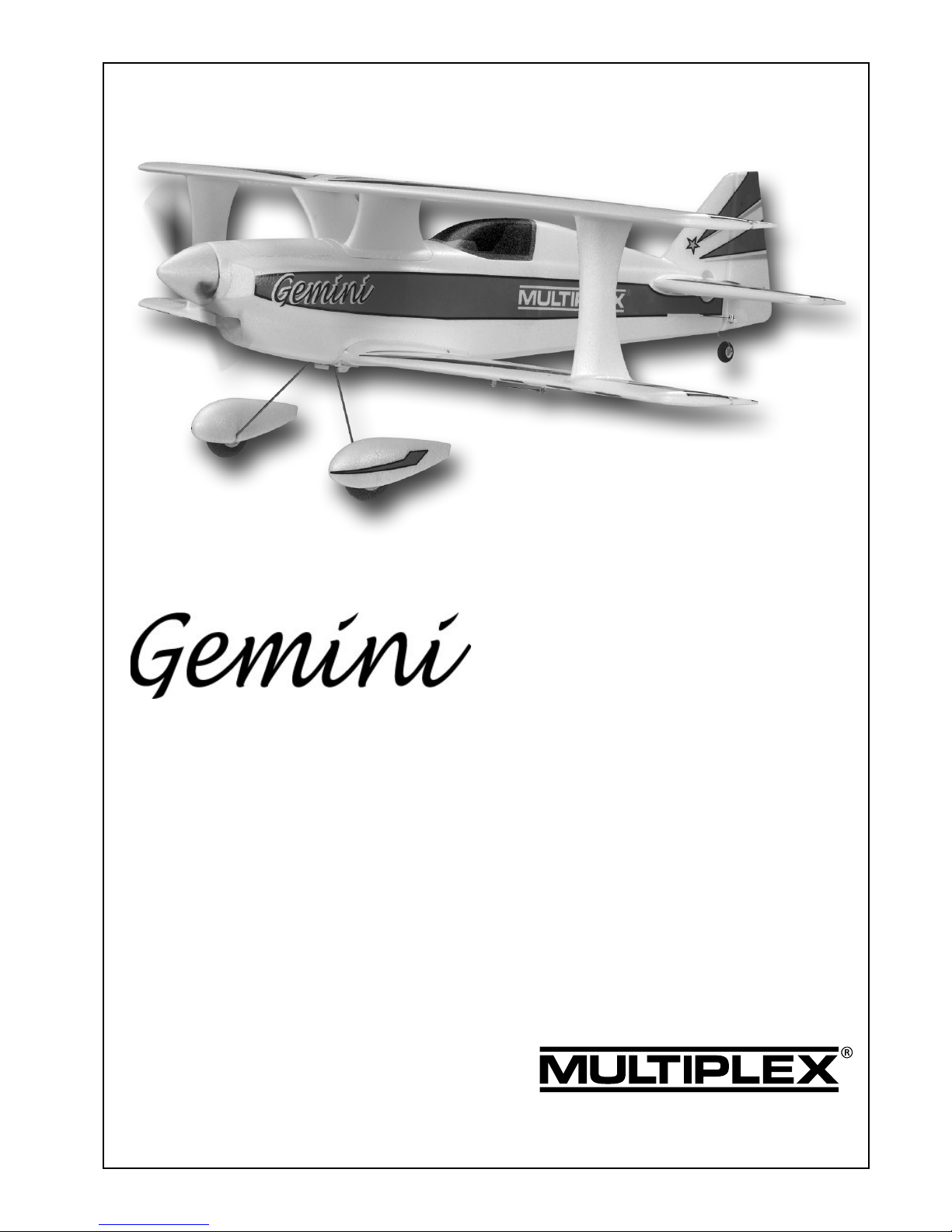
Building instructions
Kit # 21 4224
©
Copyright by MULTIPLEX 2007 ver. 1.0 engl.
Page 2

2
Safety notes
Before every flight check that the motor and propeller are in place and secure - especially after transporting the
model, and after hard landings and crashes. Check also that the wing is correctly located and firmly secured on the
fuselage before each flight.
Don’t plug in the battery until you have switched on the transmitter, and you are sure that the motor control on the
transmitter is set to “OFF”.
When the model is switched on, ready to fly, take care not to touch the propeller. Keep well clear of the propeller
disc too, and ask spectators to stay back.
Allow the motor to cool down after each flight. You can check this by carefully touching the motor case with your
finger. The temperature is correct when you can hold your finger on the case without any problem. On hot days this
may take up to 15 minutes.
Please keep in mind at all times: don’t fly towards people or animals.
Page 3

3
# 21 4224
Examine your kit carefully!
MULTIPLEX model kits are subject to constant quality checks throughout the production process, and we sincerely
hope that you are completely satisfied with the contents of your kit. However, we would ask you to check all the parts
(referring to the Parts List) before you start construction, as we cannot exchange components which you have
already worked on. If you find any part is not acceptable for any reason, please take the kit back to your model shop in
the first instance, as he will be able to advise you. After checking, he will send the component or the kit to our Quality
Control department. We can only process guarantee claims if the purchase receipt and a brief description of the fault
are supplied.
We are constantly working on improving our models, and for this reason we must reserve the right to change the kit
contents in terms of shape or dimensions of parts, technology, materials and fittings, without prior notification. Please
understand that we cannot entertain claims against us if the kit contents do not agree in every respect with the
instructions and the illustrations.
Caution!
Radio-controlled models, and especially model aircraft, are by no means playthings. Building and operating
them safely requires a certain level of technical competence and manual skill, together with discipline and a
responsible attitude at the flying field. Errors and carelessness in building and flying the model can result in
serious personal injury and damage to property. Since we, as manufacturers, have no control over the
construction, maintenance and operation of our products, we are obliged to take this opportunity to point out
these hazards and to emphasise your personal responsibility.
Additional items required:
e.g. MULTIPLEX Micro IPD receiver 35 MHz, A-band Order No. 5 5971
alternatively 40 MHz Order No. 5 5972
or MULTIPLEX RX-7 SYNTH DS IPD receiver 35 MHz, A-band Order No. 5 5885
MULTIPLEX Nano-S servo 2 x required for ailerons Order No. 6 5120
2 x required for elevator / rudder
Servo extension lead 3 required for aileron servos Order No. 8 5031
”Gemini” power set: HiMax HC 2816-0890
Contents: 1 HC 2816-0890 motor
1 APC 10” x 5” E propeller
1 Driver for Elapor spinner, 4 mm Ø split taper collet
1 BL 27 speed controller
Flight battery:
MULTIPLEX flight pack, e.g. LiBatt 3/1-2100 mAh (load capacity approx. 36 A) Order No. 15 7131
Adhesive: cyano-acrylate
Use medium and high-viscosity cyano-acrylate glue (”cyano” - not styrofoam cyano) for this model. Epoxy adhesives
produce what initially appears to be a sound joint, but the bond is only superficial, and the hard resin breaks away from
the parts under load. Hot-melt glue (from a glue gun) is an excellent alternative adhesive, especially for servo mounting.
Tools:
Scissors, balsa knife, combination pliers, long pointed-nose pliers, slot-head / cross-point screwdrivers (for the servo
output arm screws).
Specification:
Wingspan 920 mm
Overall fuselage length 920 mm
All-up weight, min. 840 g
Wing area 34 dm²
Wing loading (FAI) min. 25 g / dm²
RC functions Rudder, elevator, ailerons and throttle
Page 4

4
Important note
This model is not made of styrofoam™, and it is not possible to glue the material using white glue or epoxy. Please be sure to use
cyano-acrylate glue exclusively, preferably in conjunction with cyano activator (”kicker”). We recommend medium or high-viscosity
(thick) cyano. This is the procedure with Elapor®: spray cyano activator on one face of the joint; allow it to air-dry for around two
minutes until the surface appears to be ”dry”, then apply cyano adhesive to the other face. Join the parts, and immediately
position them accurately.
Please take care when handling cyano-acrylate adhesives. These materials harden in seconds, so don’t get them on
your fingers or other parts of the body.
We strongly recommend the use of goggles to protect your eyes.
Keep the adhesive out of the reach of children!
1. Before assembling the model:
Please check the contents of your kit before you start construction.
You will find Figs. 01 + 02 and the Parts List helpful here.
2. Preparing the control ”snakes”
The first step is to cut the plastic outer and inner snake sleeves to
the lengths stated below. The sleeves are best cut by placing
them on a hard flat surface and rolling them to and fro under the
blade of a balsa knife; the sleeves can then simply be broken off
at the scored points.
3 mm Ø x 2 mm Ø outer snake sleeves
2 x 52 = 300 mm
2 mm Ø x 1 mm Ø inner snake sleeves
2 x 53 = 320 mm
3. Completing the control snakes
Prepare the snakes as follows prior to installing them: slip the
inner sleeves 53 into the outer sleeves 52, and slide the steel
rods 51 into the inner sleeves.
4. Preparing the fuselage shells
The Nano-S servos for rudder and elevator should now be installed
in the fuselage shells 2 + 3. Place the servos in the recesses, and
apply a drop of thick cyano or hot-melt glue to the mounting lugs
to hold them in place.
Fig. 03
Stand the fuselage shells on a flat surface, and connect the preformed end of the steel pushrods (with snake sleeves fitted) to
the servo output arms, using the outermost hole in the levers.
Apply cyano to the snake channels, then press the snakes into
them as far as they will go (press against them from the inside)
until the adhesive has set hard.
Fig. 04
5. Installing the motor mounts
The motor mounts 39 (2 x) can now be glued in the fuselage
shells on both sides using cyano. Ensure that the motor mounts
39 are a snug, accurate fit in the foam components before you
apply glue. Sand the joint surface of the plastic mouldings and
glue them in place very securely. The quality of these joints dictates
whether the motor stays attached to the fuselage or not!
Fig. 05
6. Canopy latch
Glue the latch catches 22 in the fuselage shells as shown in Fig.
05.
7. Preparing the wing screw supports
Glue parts 32 + 33 together in pairs using cyano. You may find it
useful to press them together using a pair of pliers. Protect your
eyes!
Fig. 06
Glue both wing screw supports 32 / 33 in the fuselage shell 3.
Fig. 07
8. Joining the fuselage shells
Temporarily tape the servo leads to the fuselage so that they do
not get in the way when you are joining the fuselage shells. Hold
the fuselage shells 2 + 3 together ”dry” (no glue), and check that
everything fits together without requiring force. Apply thick cyano
to one face, join the shells and align them carefully before the
glue starts to set; this normally takes about ten seconds, but varies
according to humidity. Hold the fuselage in your hands for another
two or three minutes, checking continually that it is still perfectly
straight, because the glue takes at least this length of time to
harden sufficiently.
Fig. 08
9. Completing the front fuselage hatch and canopy
Insert the latch tongues 23 and set them to approximately the
right position. Fit the front hatch 4 on the fuselage under light
pressure, allowing the tongues to take up their correct position.
Carefully open the hatch, bend the latch tongues 23 slightly to
one side and apply cyano in the gap. Straighten them immediately,
and allow the glue to set hard.
Fig. 09
Repeat the procedure with the canopy frame 5. Check that the
canopy 19 is an accurate fit on the canopy frame, place it on the
fuselage, and fix the canopy to the frame using a few drops of
glue. Let the glue harden, then lift off the canopy assembly and
reinforce the joints with more glue.
Figs. 10 + 11
If you wish, you can cut down the canopy to form a simple
windshield, transforming the ”saloon” into an ”open-top” machine.
10. Preparing the tailplane
Move the elevators to and fro to free up the hinges. Attach the
swivel pushrod connector to the elevator horn, and glue it in the
recess in the elevator 12. Secure the nut 27 on the pushrod
connector 25 using a drop of glue.
Fig. 12
11. Gluing the tailplane to the fuselage
Place the tailplane 12 on the fuselage ”dry” (no glue), and check
that it is possible to set it exactly central and horizontal. Glue it in
place using cyano, and pin it in the correct position before the
glue sets.
Fig. 13
12. Preparing the fin
Move the rudder to and fro (about ten to twenty times) to free up
the hinge.
Slip the wire tailwheel unit 68 through the glue-fitting tailwheel
bracket 37, fit it through the glue-fitting horn 36 and use a pair of
combination pliers to bend the end over at 90° as close as possible
to the horn, as shown in Fig. 14.
The horn 36 can now be glued to the rudder, applying cyano only
from the underside. When the glue has set hard, cut a slot about
Page 5

5
1.5 mm deep above the horn to accept the tailwheel wire.
Rotate the tailwheel wire 68 over the horn 36, align the tailwheel
unit, and glue the wire to the rudder using plenty of cyano.
Figs. 14 - 15
Mount the swivel pushrod connector on the rudder horn, and
secure the nut with a drop of paint or glue.
Fig. 15
13. Glue the fin to the fuselage
Fig. 16
The tailwheel 69 can now be fitted: slip one wheel retainer (tubular
rivet) 70 on the wire, followed by the wheel and the second retainer.
Glue the retainers 70 to the wire using a drop of cyano.
Caution: apply small drops of glue on the tip of a small screwdriver
or similar. Please don’t glue the wheel to the axle!
Fig. 17
14. Preparing the cabane
Remove the cabane moulding 6 (L / R) from the moulding sprue.
Glue the following parts together: 2 x 6 (cabane), 34 (glue-fitting
screw sleeve) and 7 (cabane centre piece).
Fig. 18
15. Decals!
Before you carry out any more work, it makes sense to apply the
decals to the wings, as access will never be as good again!
16. Completing the top wing
Glue the GRP spar 50 in the channel in the underside of the top
wing 11, after checking that the channel is the correct length;
apply the glue to the full length of the spar. Take great care to
keep the wing exactly flat and straight while the glue is curing.
Release the ailerons by cutting along the marked lines at both
ends. Free up the hinges by moving them to and fro repeatedly.
Glue the cabane assembly 6 / 7 to the top wing.
Fig. 19
Trim the wing struts 10 and 9 to fit before gluing them to the
underside of the top wing. Before reaching for the glue, check
that you are fitting the left strut to the left wing (right to right), and
that the struts are the right way up!
Figs. 20 + 21
17. Installing the aileron linkages
Glue the flat link horns 35 in the ailerons of the top wing 11, with
the small 1.6 mm Ø holes projecting.
Fig. 22
18. Completing the bottom wing
Mount the swivel connectors on the aileron horns 24 and glue
them to the bottom ailerons. Repeat the procedure with the flat
link horns 35, but this time with the 2.5 mm Ø holes projecting;
the swivel connectors for the aileron link pushrods are fitted in
these holes.
Fig. 23
Install the servos and the aileron pushrods 30, set the servos to
centre from the transmitter, and adjust the linkages so that the
ailerons are at neutral.
Fig. 24
19. Installing the main undercarriage retainer
The undercarriage retainer 66 is installed in the moulded-in recess
in the bottom wing. Press it into place ”dry” first, so that the
projecting tongues are forced into the foam, then simply glue it in
place with plenty of cyano. Glue the wing screw sleeve 34 in the
recess in the bottom wing, again using cyano.
Fig. 25
20. Joining and completing the top and bottom wings
The wing struts can now be glued to the bottom wing.
Fig. 26
Connect the aileron link pushrods 54, fit them through the swivel
connectors at the bottom, and tighten the grubscrews. Check that
all four ailerons are at neutral, then cut the bottom ailerons free
(1 mm gap at both ends).
Fig. 27
21. Preparing the wheel spats (replacement part No. 22 4204)
Glue the holders for the wheel spats 65 into the right and left
outer spat shells 16 / 17. Fit the collets 62 on both sides together
with the 5 mm socket-head grubscrews 64. Join the wheel spats
and glue the inner shells 14 / 15 to the outer shells 16 / 17 using
cyano.
Fig. 28
22. Assembling and installing the main undercarriage
First check the wheel tracking as shown in the drawing, and correct
it if necessary.
Fig. 29
Attach the inner collets 62, and fit the wheels 61 together with the
wheel spat assemblies. Align the parts and tighten the grubscrews
63 in the outer collets 62 to hold everything in place. Snap the
wire undercarriage unit 60 in the plastic retainer, and secure it
with the screw 67.
23. Provisional final assembly
Gently widen the gap between the wings so that the fuselage fits
between them, insert the fuselage, and connect the aileron servo
leads. Gently prise the bottom wing away from the wing saddle,
and thread the servo connectors into the fuselage. Fix the wings
to the fuselage using the two plastic M5 screws 31.
Figs. 30 + 31
24. Installing the motor
We recommend the use of the Gemini power set, Order No. 33
2634. Attach the motor to the motor bulkhead 40; the end of the
shaft should project beyond the face of the motor bulkhead by 10
mm.
Fig. 32
If the shaft projects more than this (for example, if you are using
a different make of motor) you will need to add packing pieces
behind the motor.
25. Attaching the motor bulkhead to the motor mounts
The motor sidethrust and downthrust can be altered by adjusting
the motor mounts 39 relative to the motor bulkhead 40. The motor
mount is asymmetrical by nature; if the four adjustor screws 41
are fitted flush, the motor is installed with maximum sidethrust
and no downthrust. We recommend the following base set-up;
note that the motor bulkhead is viewed from behind (!).
Top left adjustor screw 0.5 mm = approx. 1 turn
Top right adjustor screw 0.5 mm = approx. 1 turn
Bottom left adjustor screw 0.5 mm = approx. 1 turn
Bottom right adjustor screw 0.5 mm = approx. 1 turn
The fuselage nose is designed to be sanded down to line up with
the spinner, using sharp paper and a sanding block, but you should
not do this until you have carefully determined the correct motor
thrustline through test-flying, as this affects the position of the
spinner.
26. Receiving system components
1. The motor is already installed
2. The speed controller fits behind the motor, suspended on its
Page 6

6
cables
3. Install the 2100 mAh LiPo battery in the battery compartment
aft of the motor, adjust its position to obtain the correct Centre of
Gravity, then secure it with Velcro tape.
4. Stow the receiver and cables in the space below the cabin, and
hold them in place with Velcro.
Velcro tape 20 + 21 is supplied in the kit to hold these parts in
place.
27. Centre of Gravity
The CG should be borne in mind when you are installing the RC
system components, to avoid the need for ballast as far as
possible.
The CG should be within the range 75 mm aft of the leading edge
”nose” of the top wing. The moulded-in dimples adjacent to the
cabane indicate the correct balance point.
Fig. 33
28. Initial test-run
All the radio control components are installed and connected.
Check the base settings of the control surface travels and the
direction of servo rotation. Ensure that the hinges are free-moving.
Check the direction of rotation of the motor shaft, and reverse it if
necessary.
29. Fitting the propeller
Assemble and install the propeller as shown in Fig. 32. The
propeller driver 38 doubles up as the mounting for the EPP spinner
18.
30. Model settings (guideline only):
CG: 75 mm (top wing)
Longitudinal dihedral: top -1°, bottom +1°
Downthrust: 0°
Sidethrust: 2 - 4° (right)
31. Control surface travels:
Measured at the widest point of the control surfaces
Ailerons: 16/12 mm +/Elevator: 12/10 mm +/Rudder: 20 mm L/R
Exponential: ailerons 30%
32. Test-flying:
Centre of Gravity
Start by balancing the model within the stated range. Once you
have test-flown the model, you can fine-tune the setting as follows:
fly straight and level at half-throttle, and roll the model inverted. If
you now have to apply a great deal of ”down” to hold level flight,
the model is nose-heavy; the CG must be shifted further aft. If the
machine climbs whilst inverted, without requiring elevator
correction, the CG is too far aft. When balanced correctly, the
model will require slight down-elevator for level inverted flight.
Correcting straight and level flight:
First the static balance: support the model by the spinner and the
rudder: with the fuselage level, the wings should remain horizontal. If not, add ballast to the lighter wingtips.
On the next flight, fly the aeroplane at minimum throttle (just
enough power to keep the model in the air), keep it straight and
level, and adjust the trims for straight flight. Now switch to inverted
and check the straight flying characteristics. If necessary, adjust
the wingtip ballast after landing the model.
Sidethrust:
Apply full throttle and fly the model straight and level past yourself
before pulling up into a vertical climb. When ascending vertically
the model should not exhibit any tendency to veer off to right or
left. If this is not the case, adjust the sidethrust to correct the fault.
Repeat the test several times, as any sidewind will tend to falsify
the model’s track.
Downthrust:
Apply full throttle and fly the model straight and level until it is
level with you, so that you have a clear view of the model from
one side. Pull the aircraft up into a vertical climb: it should continue
to climb vertically, and not fall away forward or back. If this is not
the case, adjust the motor downthrust to correct the fault.
After these tests you may find it necessary to repeat the CG tests.
Aileron differential:
Fly three or four rolls to the right at half-throttle; if the Gemini
veers to the right during this manoeuvre, you need to increase
the aileron differential. If it veers to the left, i.e. against the direction
of rolling, you should reduce the aileron differential.
33. Gilding the lily - applying the decals
The kit is supplied with a multi-colour decal sheet, part 1. Cut out
the individual name placards and emblems and apply them to the
model in the positions shown in the kit box illustration, or in another
arrangement which you find pleasing.
34. Safety
Safety is the First Commandment when flying any model aircraft.
Third party insurance should be considered a basic essential. If
you join a model club suitable cover will usually be available
through the organisation. It is your personal responsibility to ensure
that your insurance is adequate for the type of model (powered
model aircraft).
Make it your job to keep your models and your radio control system
in perfect order at all times. Check the correct charging procedure
for the batteries used in your RC set. Make use of all sensible
safety measures and precautions which are advised for your
system. An excellent source of practical accessories is the MULTIPLEX main catalogue, as our products are designed and
manufactured exclusively by practising modellers for other
practising modellers.
Always fly with a responsible attitude. You may think that flying
low over other people’s heads is proof of your piloting skill; others
know better. The real expert does not need to prove himself in
such childish ways. Let other pilots know that this is what you
think too. Always fly in such a way that you do not endanger
yourself or others. Bear in mind that even the best RC system in
the world is subject to outside interference. No matter how many
years of accident-free flying you have under your belt, you have
no idea what will happen in the next minute.
We - the MULTIPLEX team - wish you many hours of pleasure in
building and flying your new model. Happy landings!
MULTIPLEX Modellsport GmbH & Co. KG
Model Development Dept.
Klaus Michler
Page 7

7
Parts List - Gemini KIT
Part No. Description Material Dimensions
No. off
1 KIT building instructions Paper, 80 g / m² A4
1 1 Decal sheet Printed self-adhesive film 700 x 1000 mm
2 1 L.H. fuselage shell Moulded Elapor foam Ready made
3 1 R.H. fuselage shell Moulded Elapor foam Ready made
4 1 Front fuselage hatch Moulded Elapor foam Ready made
5 1 Canopy frame Moulded Elapor foam Ready made
6 1 L.H. / R.H. cabane Moulded Elapor foam Ready made
7 1 Cabane centre piece Moulded Elapor foam Ready made
8 1 Bottom wing Moulded Elapor foam Ready made
9 1 L.H. wing strut Moulded Elapor foam Ready made
10 1 R.H. wing strut Moulded Elapor foam Ready made
11 1 Top wing Moulded Elapor foam Ready made
12 1 Tailplane Moulded Elapor foam Ready made
13 1 Fin Moulded Elapor foam Ready made
14 1 Left inner wheel spat Moulded Elapor foam Ready made
15 1 Right inner wheel spat Moulded Elapor foam Ready made
16 1 Left outer wheel spat Moulded Elapor foam Ready made
17 1 Right outer wheel spat Moulded Elapor foam Ready made
18 1 Spinner Moulded Elapor foam Ready made, 62 Ø
19 1 Canopy Vac. moulded plastic Ready made
Small parts set
20 3 Velcro tape, hook Plastic 25 x 60 mm
21 3 Velcro tap, loop Plastic 25 x 60 mm
22 4 Latch catch Injection-moulded plastic Ready made
23 4 Latch tongue Injection-moulded plastic Ready made
24 3 Glue-fitting control surface horn Injection-moulded plastic Ready made
25 6 Swivel pushrod connector Metal Ready made, 6 mm Ø
26 6 Washer Metal M2
27 6 Nut Metal M2
28 8 Socket-head grubscrew Metal M3 x 3 mm
29 1 Allen key Metal 1.5 mm A/F
30 2 Aileron pushrod, one Z-bend Metal 1 Ø x 70 mm
31 2 Wing screw Plastic M5 x 50 mm
32 2 Wing screw support A Injection-moulded plastic Ready made, M5
33 2 Wing screw support B Injection-moulded plastic Ready made, M5
34 2 Glue-fitting sleeve for M5 screw Injection-moulded plastic Ready made
35 4 Glue-fitting link horn, flat, 1.3 Ø + 2.5 Ø Injection-moulded plastic Ready made
36 1 Glue-fitting tailwheel horn Injection-moulded plastic Ready made
37 1 Glue-fitting tailwheel bracket Injection-moulded plastic Ready made
38 1 Spinner holder Injection-moulded plastic Ready made
39 2 Motor mount Injection-moulded plastic Ready made
40 1 Motor bulkhead Injection-moulded plastic Ready made
41 4 Adjustor screw, motor bulkhead mounting Metal M3 x 10 mm
42 2 Motor bulkhead mounting screw Metal M3 x 16 mm
Wire and tube set
50 1 Tubular spar GRP tube 6 Ø x 3.4 Ø x 575 mm
51 2 Steel pushrod, elevator + rudder, one Z-bend Metal 0.8 Ø x 355 mm
52 2 Snake outer sleeve, elevator + rudder Plastic 3 Ø x 2 Ø x 300 mm
53 2 Snake inner sleeve, elevator + rudder Plastic 2 Ø x 1 Ø x 320 mm
54 2 Aileron link pushrod Metal 1.3 Ø x 185 mm
Undercarriage set
60 1 Main undercarriage Spring steel 2.5 Ø, ready made
61 2 Lightweight wheel Plastic, EPP 53 Ø, hub bore 2.6
62 4 Collet Metal 2.7 Ø x 8 Ø x 5 mm
63 2 Socket-head grubscrew Metal M3 x 3 mm
64 2 Socket-head grubscrew Metal M3 x 5 mm
65 2 Wheel spat holder Plastic Ready made
66 1 Undercarriage retainer Plastic Ready made
67 1 Screw Metal M3 x 12 mm
68 1 Tailwheel unit Metal 1.3 mm Ø
69 1 Lightweight tailwheel Foam rubber 26 mm Ø
70 2 Tailwheel retainer (tubular rivet) Metal A2.0 x 0.2 x 3
Page 8

8
Page 9

9
Abb. 01
Abb. 02
8
14
60
13
12
4
18
2
11
50
52
53
51
31
61
66
67
33
32
42
41
40
38
65
3 x 20
3 x
21
29
3
6
7
6
5
19
17
15
16
10
9
39
39
2345678901234567890
1
2345678901234567890
1
2345678901234567890
1
2345678901234567890
1
22
123456789012345678
123456789012345678
123456789012345678
123456789012345678
123456789012345678
30
23
63
64
25
26
27
28
35
24
23
36
37
69
70
68
23
34
Inbus 1,5 mm
Page 10

10
Abb. 03
Abb. 05
Abb. 07
Abb. 04
Abb. 06
Abb. 08
Abb. 09 Abb. 10
3
51, 52, 53
3
CA
CA
CA
CA
CA
CA
41
5
32
33
3
4
2
CA
CA
39
22
22
alternativ
alternativ
CA
23
19
23
alternativ
Page 11

11
Abb. 11
Abb. 12
Abb. 13
Abb. 14
Abb. 15
Abb. 16
Abb. 17
Abb. 18
4
19
12
CA
12
37
37
CA
4
7
8
5
CA
CA
69
6
5
4
90°
ca. 5-7 mm
36
12
13
CA
6
34
7
70
27, 26, 24, 25, 28
Page 12

12
Abb. 19
Abb. 21
Abb. 20
Abb.22
Abb. 23
Abb. 24
Abb. 25
Abb. 26
50
11
4
11
CA
CA
CA
CA
11
11
27, 26, 24, 25, 28
CA
8
CA
66
CA
CA
9
8
6
6
11
11
6
6
9
6
6
35
! Ø 1,6 mm
! Ø 2,5 mm
27, 26, 35, 25, 28
30
34
8
11
Page 13

13
Abb. 27
Abb. 29 Abb.30
Abb. 31
Abb. 32
Abb.33
Abb. 34
11
8
4
1 mm
65
=
= -5
mm
Power Set
# 33 2634
CG
75 mm
54
16
61
14
67
15
17
ESC
Page 14

14
Page 15

15
Page 16

16
MULTIPLEX Modellsport GmbH & Co.KG Westliche Gewerbestrasse 1 D-75015 Bretten (Gölshausen) www.multiplex-rc.de
ERSATZTEILE
(bitte bei Ihrem Fachhändler bestellen)
REPLACEMENT PARTS
(please order from your model shop)
PIECES DE RECHANGES
(S.V.P. à ne commander que chez votre revendeur)
PARTI DI RICAMBIO
(da ordinare presso il rivenditore)
REPUESTOS
(por favor, diríjase a su distribuidor)
# 22 4214
Rumpfhälften+Bowdenzüge
Fuselage shells + snakes
Fuselage+gainesde
commande
Semigusci fusoliera + bowden
Fuselaje + trans. bowden
# 22 4215
Kabinenh.+ Rahmen+Deckel
Canopy + frame + top decking
Verrière + support de verriére+
capot moteur
Capottina + telaio + coperchio
fusoliera
Cabina +marco + tapa del
fuselaje
# 22 4216
Tragflächen-Streben
Wing struts
Haubans
Montanti alari
Riostras
# 22 4218
Seiten- u. Höhenleitwerk
Tail set
Empennage
Piani di coda
Kit de timones
# 72 3185
Holmrohr
Tubular spar
Clé d‘aile
Tubo baionetta
Larguero
# 70 3455
Gestängeanschluss (2x)
Pushrod connector (2x)
Element de fixitation (2x)
Raccordo rinvii (2x)
Conexión del verillaje (2x)
# 22 4206
Fahrwerkssatz mit Rädern
Undercarriage set with wheels
Train d‘atterrissage avec roues
Kit carrello con ruote
Kit del tren de aterrizaje,
con ruedas
# 72 3135
Fahrwerkshalter mit Schraube
Undercarriage retainer and
screw
Support de train, avec vis
Supporto carrello con vite
Soporte del tren con tornillos
# 72 5136
Canopy-Lock (2 Paar)
Canopy-Lock (2 paires)
Canopy Lock (2 pairs)
Canopy-Lock (2 coppie)
Cierre de cabina (2 pares)
# 22 4219
Kleinteilesatz
Small items set
Petit nécessaire
Minuteria
Piezas pequeñas
# 72 4453
Dekorbogen
Decal sheet
Planche de décoration
Decals
Lámina decorativa
# 22 4217
Tragflächen
Wings
Ailes
Semiali
Alas
 Loading...