

Page 1

Equipment Installation Instructions for
Water Valve Kit
This kit is designed to be installed on the following towers only:
Model 116 Front Draw Tower (made after 07/96) (P.N. 911635)
Model 116X Front Draw Tower (made after 07/96) (P.N. 911636)
Model 156 Pass-Thru Tower, Right (P.N. 915641)
Model 156 Pass-Thru Tower, Left (P.N. 915645)
Model 156X Pass-Thru Tower, Right (P.N. 915650)
Model 156X Pass-Thru Tower, Left (P.N. 915654)
Foodservice Group
Caution
DO Adhere to all National and Local Plumbing and Electrical Safety Codes.
DO Turn “off” incoming electrical service switches when servicing, installing, or repairing equipment.
DO Use caution when handling metal surface edges of all equipment.
WARNING: DANGER OF ELECTRICAL SHOCK
Disconnect and lock out all electrical power sources
before performing service or maintenance on this
machine -- except when electrical tests are being
performed by qualified service personnel.
Manitowoc Beverage Equipment
2100 Future Drive Sellersburg, IN 47172-1868
Tel: 812.246.7000, 800.367.4233 Fax: 812.246.9922
www.manitowocbeverage.com
In accordance with our policy of continuous product development and improvement,
this information is subject to change at any time without notice.
EI216697 Issued (JMT/KAZ) 08/13/96
Page 2
Equipment Installation Instructions
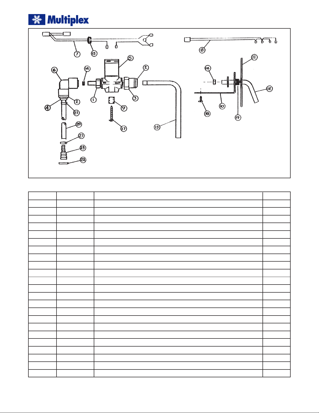
Figure 1
Item Part No. Description Quantity
1* 00111005 Adaptor, 1/8 MPT x 5/16 Stem 1
2* 00208803 Cover, 3/8 Collet 2
3* 00209317 Adaptor, 1/8 MPT x 3/8 Tube 1
4* 00210752 Adaptor, 1/4 Barb x 3/8 Stem 1
5* 00211658 Valve, Two Way, 24 VAC 1
6* 00213885 Elbow, 3/8 Tube x 5/16 Tube 1
7 00216696 Wire Harness, Water Valve 1
8 00213146 Wire Harness, Portion Control 1
9 00216728 Spacer, Standoff, 1/2"2
10 00216730 Mounting Bracket, 156 Tower 1
11 00216731 Escutcheon Plate, 156 Tower 1
12 00216732 Spout Assembly, 156 Tower 1
13 00216735 Spout, 146 Tower 1
14* 00551303 Button, Water Flow 1
15 00800533 Bushing, 7/8" Hole 1
16 00850701 Hex Nut, #6-32 2
17 00851214 Screw, #10 x 1" 2
18 00853004 Screw, #10 x 1/2"2
19 PE500651 Tube, Spout Sleeve 1
20 PE021230 Tubing, Polyethylene 3 ft.
21 00855114 Tab-Clamp, #105 2
22 00855128 Tab-Clamp, #198 2
23 00861317 Splice, 1/2 x 1/4 Barb-Stem 1
*These items are pre-assembled.
2
EI216697 Issued (JMT/KAZ) 08/13/96
Page 3

Equipment Installation Instructions
Installation of the Front Draw Tower
1. Turn “off” the power switch on the dispensing tower.
2. Remove top cover and rear cover panels.
3. Remove wire harness connecting the far left dispensing valve (labeled “#1”) to the electronic portion control board and the front-mounted water switch.
4. Connect the left dispensing valve to the portion control board with the new harness provided in this kit.
5. Assemble the water valve to the mounting plate directly behind the left dispensing valve as shown in
figure 2. Use 1/2" spacers under the valve.
Figure 3
10. Turn the water supply “on” and check for leaks.
11. Turn “on” the power switch and test installation by
pressing the front mounted water switch. Water should
dispense.
12. Replace tower rear panel and the top cover.
Installation of the Pass-Thru Tower
1. Turn “off” the power switch on the dispensing tower.
2. Remove the top cover, “wide” stanchion access panel,
and cover plate concealing the family of holes in the
front edge of stanchion.
3. Remove wire harness connecting the dispensing valve
(adjacent to the “wide” stanchion) to the electronic
portion control board and the stanchion-mounted
water switch.
Figure 2
6. Connect the water valve wire harness to the valve and
front mount water switch common and normally open
terminals.
7. Insert the plastic bushing in the hole adjacent to the
water valve and route the connector end of cord down
through the bushing. Disconnect one (1) of the tower
power supply cords and reconnect in series with the
water valve cord as shown in figure 3.
8. Insert scribed end of the stainless steel spout tube into
the outlet fitting of the water valve with the spout projecting down through the hole located in the splash
panel between the first and the second dispensing
valves.
9. Make appropriate water supply connection to the
water inlet tube.
EI216697 Issued (JMT/KAZ) 08/13/96
4. Connect the dispensing valve to the portion control
board with the new harness provided in this kit.
5. Insert the spout assembly into the outlet fitting of the
water valve and attach the mounting bracket with #10
x 1/2" screws as shown in figure 4.
Figure 4
3
Page 4

Equipment Installation Instructions
6. Guide spout through the lower rectangular hole in
the stanchion and through the hole in the Esutcheon
plate. Align the threaded studs on the Escutcheon plate
through the holes in the stanchion and the mounting
bracket. Secure with #6-32 hex nuts (provided) (see
figure 5).
7. Connect the water valve wire harness to the valve coil
and the water switch in the stanchion above the water valve.
8. Disconnect one (1) of the tower power supply cords
and reconnect in series with the water valve cord as
shown in figure 3.
9. Make the appropriate water supply connection to the
water valve inlet tube.
10. Turn “on” the water supply and check for leaks.
11. Turn the power switch “on” and test the installation
by pressing the water switch above the spout. Water
should dispense.
12. Replace the Stanchion access panel and the top cover.
Figure 5
4
EI216697 Issued (JMT/KAZ) 08/13/96
 Loading...