

Page 1
MultiModem
TM
CDMA
External Wireless Modem
(Data/Fax/Voice)
MTCBA-C
User Guide
Page 2

User Guide for MultiModem CDMA
External Data/Fax/Voice Wireless Modem
MTCBA-C
P/N 82001130, Revision A
Copyright © 2003 by M ulti-Tech Systems, Inc.
All rights reserved. This publication may not be reproduced, in whole or in part,
without prior expressed written permission from Multi-Tech Systems, Inc.
Multi-Tech Systems, Inc. makes no representation or warranties with respect to
the contents hereof and specifically disclaims any implied warranties of
merchantability or fitness for any particular purpose. Furthermore, Multi-Tech
Systems, Inc. reserves the right to revise this publication and to make changes
from time to time in the content hereof without obligation of Multi-Tech Systems,
Inc., to notify any person or organization of such revisions or changes.
Revision Date Description
A 7/15/03 Initial Release, Rev A.
2
Page 3

Contents
PRODUCT DESCRIPTION 5
Package Contents 6
Interfaces 6
Parts to be Supplied by End User 7
Antennas 8
Accessory Kit 9
AT Command Info 10
Phone Number for the Wireless Modem 10
Network Access 11
Features 12
A
PPLICATION OVERVIEW 13
Application Types 13
Benefits/Features in Applications 15
Functions – CDMA Modes 17
S
PECIFICATIONS 18
General Specifications 18
Electrical Characteristics 19
Input/output electrical characteristics for external
connections 20
LED Indicators 21
RS232 15-Pin Connector Pinout 22
G
ETTING STARTED WITH YOUR WIRELESS MULTIMODEM 23
Mechanical Mounting 23
Electrical Installation & Configuration 26
Mobile PhoneTools 29
3
Page 4

Verifying signal strength 30
Verifying network registration 31
Testing the Configuration 32
Testing the Configuration (continued) 33
Testing the Configuration (continued) 34
TROUBLESHOOTING 35
Situation A: The modem does not answer through the
serial link 35
Situation B: The modem always returns «Error» when
trying to issue a communication 37
Situation C: The modem always returns «No carrier»
when trying to issue a communication 42
S
AFETY 44
General Safety 44
Vehicle Safety 46
Maintenance of Your Modem 46
Your Responsibility 47
W
ARRANTY & REPAIRS POLICIES 48
Warranty 48
Repairs 49
Repair Procedures for U.S. and Canadian Customers 49
Repair Procedures for International Customers
(Outside U.S.A. and Canada) 51
Repair Procedures for International Distributors 52
WIRELESS MODEM REFERENCE INFO 53
4
Page 5

Product Description
Product Description
The Multi-Tech MultiModem CDMA is an
external data/fax/voice wireless modem. It also
supports mobile originated short message service
(SMS) and mobile-terminated SMS. Designed for
global use, it offers standards-based multi-band
CDMA2000 1x perfor mance. This ready-to-deploy,
standalone modem allows developers to add
wireless communication to products with a
minimum of development time and expense. The
MultiModem CDMA is based on industrystandard open interfaces, is fully type approved,
and can be desktop or panel mounted.
5
Page 6

Product Description
Package Contents
• one modem
• two holding bridles (mounting brackets)
• one RS-232 15-to-9-pin cable
• one power supply cable with fuse
• one User Manual (this document)
Interfaces
The Wireless MultiModem has several interfaces:
• LED function indicating operating status
• External antenna (via SMA connector)
• Serial and control link (via 15 pins SUB D)
• Power supply (via 2.5mm miniature power
jack)
6
Page 7

Product Description
Parts to be Supplied by End User
• mounting screws
screw shaft diameter = .17” max.)
(
• antenna
The antenna used must be both of the
correct frequency and of the style
appropriate to the app lication.
7
Page 8
Product Description
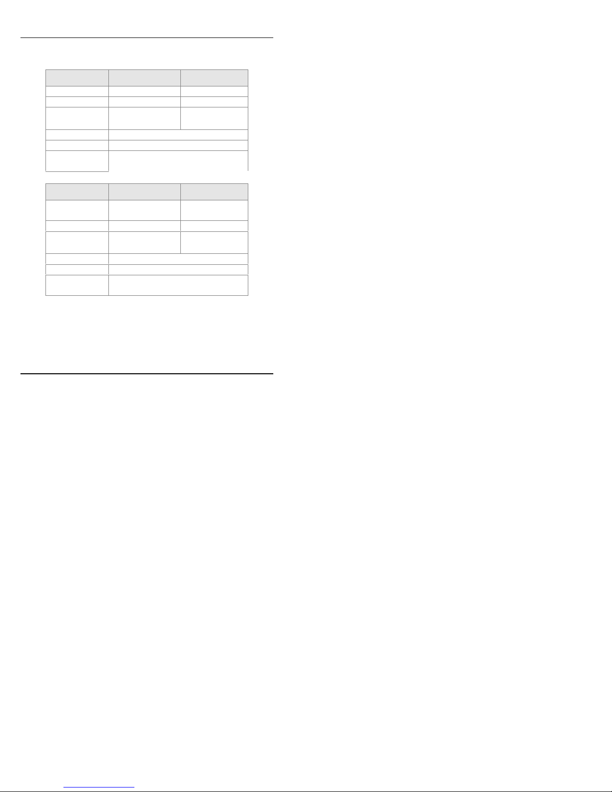
Antennas
Frequency RX 869 to 894 MHz 925 to 960 MHz
Frequency TX 824 to 849 MHz 880 to 915 MHz
RF Power
Stand
Impedance 50 ohms
VSWR <2
Typical
Radiated Gain
Frequency RX 1805 to 1880 MHz 1930 t o 1990
Frequency TX 1710 to 1875 MHz 1850 to 910 MHz
RF Power
Stand
Impedance 50 ohms
VSWR <2
Typical
Radiated Gain
GSM 850 EGSM 900
2W at 12.5% duty
cycle
0 dBi on azimuth plane
GSM 1800 GSM 1900
1W at 12.5% duty
cycle
0 dBi on azimuth plane
2W at 12.5%
duty cycle
1W at 12.5%
duty cycle
MHz
8
Page 9

Accessory Kit
A Wireless MultiModem Accessory Kit is
available. Generally speaking, it is useful to
have one or two kits to configure a group or
fleet of Wireless MultiModem units
(generally, you will not need one kit for every
modem). The kit includes an antenna, a
power supply and a product CD. The product
CD contains an AT Command manuals, other
documentation, and modem software.
Product Description
9
Page 10

Product Description
AT Command Info
This manual describes a minimal set of AT
commands that are adequate f or configuring
many common application situations. A
complete set of AT command definitions can
be found in the CDMA AT Commands
Reference Guide. This manual is available on
the MultiTech web site or on the Accessory
Kit CD.
Phone Number for the Wireless Modem
Every wireless modem will have its own
unique phone number.
10
Page 11

Network Access
The network access arrangements to be
specified in Windows Dial-Up Networking (of
the computer that the wireless modem is
serving) will vary according to the type of
wireless service used.
• For point to point data, a circuit-switched
data connection is used. The user can set
up DUN to make a conventional V.32
modem connection to any terminating
modem at the other end. The phone
number specified in DUN can be one
supplied by the wireless service provider
or another phone number related to a
different dialup modem service (e.g., a
dialup modem service phone number
from any commercial or private dialup
network).
• For CDMA 1x data, a single DUN number
is generally used by all of a wireless
provider’s subscribers throughout its area
of coverage (regional, nationwide,
continental, etc.). Rather than being a
literal phone directory number, as in
conventional DUN, this is a code that
gives the modem Internet access.
Product Description
11
Page 12

Product Description
Features
• CDMA2000 1xRTT
operation
• Dual-band 800/1900
CDMA
• Class 2.0 Group 3 FAX • Phone book management
• Desktop or panel
mounting
• Short Message Service
features including SMS
mobile originated, SMS
mobile terminated, cell
broadcast, Over the Air
Activation (OTA),
OTASP, OTAPA
• Voice features include
DTMF, telephony,
OCELP 13K, echo
cancellation
• SMA antenna connector • Real time clock
• Serial interface supports
DTE speeds to 230K
• CDMA IS-95-A, IS-95B
• AT command compatible
and Personal Information
Management (PIM)
• Fixed dialing number
• Supplementary services
including call forwarding,
call barring, multiparty,
call waiting and call hold,
calling line identification,
closed user group, call
transfer
• Numerous LEDs provide
operational status
• Alarm management
12
Page 13

Application Overview
Application Overview
Application Types
With packet data speeds up to 153K bps, the
MultiModem CDMA is targeted at applications
that periodically need to send or receive data over
a wireless network. It is an ideal solution for:
Appliances Remote Diagnostics
ATM Terminals Remote Metering
Automotive Security Systems
Data Collection Vending/Gaming
Machines
Gas Pumps Other devices
requiring wireless
connectivity.
Industrial and
Medical Remote
Monitoring Systems
Note: The Wireless
MultiModem must be
mounted with at least 8
inches (20 cm) of c l earance
from the human body.
13
Page 14
Application Overview
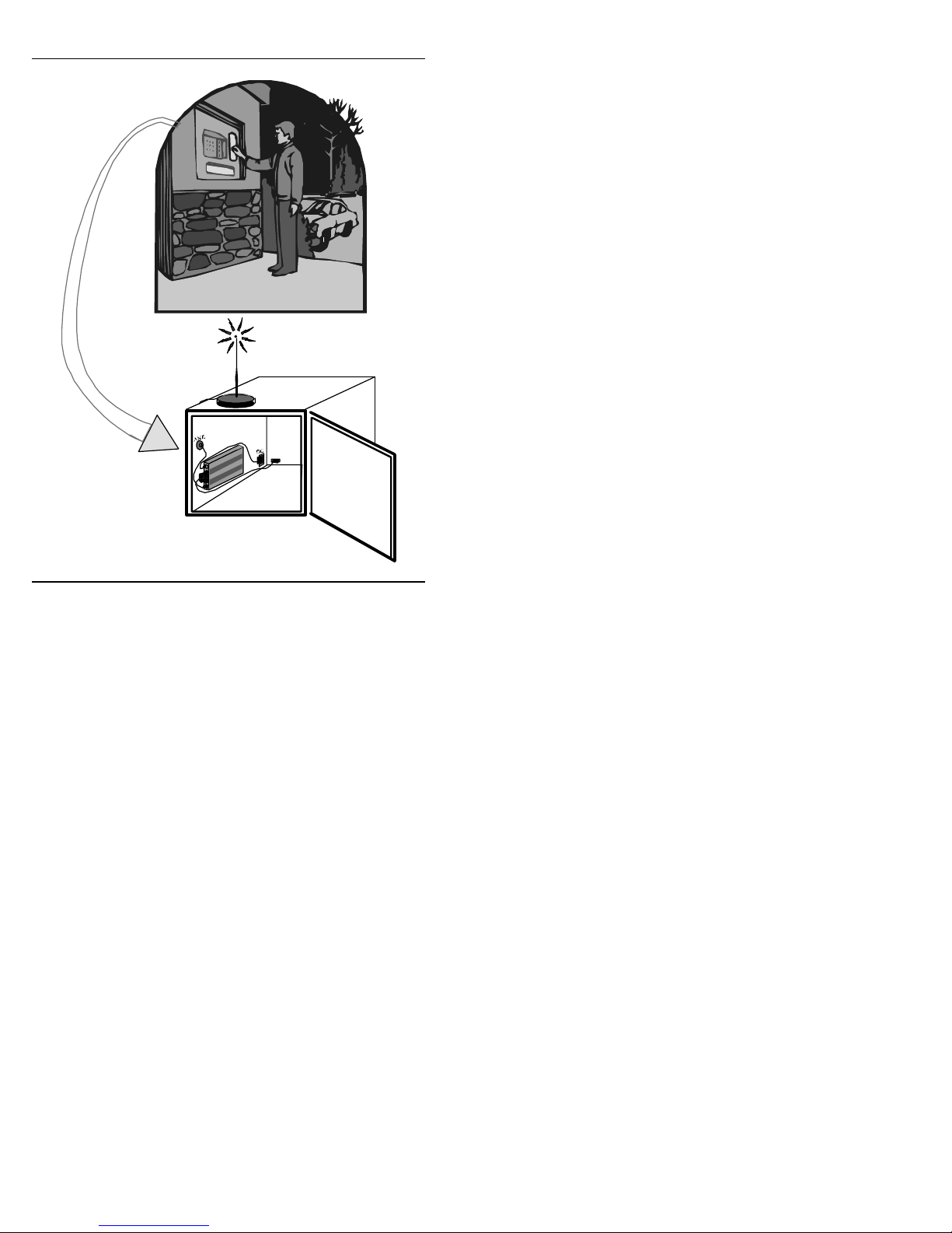
RS232
Wireless Mu ltiModem used in
remote A TM application.
14
Page 15

Application Overview
Benefits/Features in Applications
Short Development Time. The MultiModem
CDMA can make your existing and next
generation device, machine, or system,
communication-ready without requiring any
hardware changes to its design. It actually
provides faster time-to-market because it relieves
the burden and expense of obtaining network and
RF approvals. This complete, ready-to-deploy
wireless modem allows you to enhance your
product while you focus on developing its core
features.
Voice Features. The MultiModem CDMA
provides telephony and Dual Tone Multi
Frequency (DTMF) functionality as well as
QCELP (13K) and echo canc ellation.
Short Message Services. The MultiModem
CDMA offers SMS features such cell broadcast,
Over the Air Activation (OTA), OTASP, and
OTAPA. The MultiModem CDMA is SMS Mobile
Originated and SMS Mobile Terminated.
Compatible Supplementary Services. The
MultiModem CDMA is compatible with
supplementary services such as call forwarding,
call barring, multiparty, call waiting and call hold,
15
Page 16

Application Overview
calling line identification, closed user group and
call transfer.
Management Features. The MultiModem
CDMA provides advanced management features
including phone book management, fixed dialing
number, real time clock and alarm manage ment
Industry-standard Modem Commands.
MultiModem CDMA provides industry-standard
AT-style commands for ease of integration into
your existing software application.
Industrial Chassis. The MultiModem CDMA is
packaged in a rugged, water resistant, industrial
chassis. The chassis has an RS-232 DE-15
Voice/Data interface connector and a permanent
screw-type power connector. It also has an SMA
antenna connector. The chassis can be sidemounted on a panel or top-mounted on a desktop
or other surface. A set of LEDs indicate the
modem’s operational status.
Network and RF Approved. The MultiModem
CDMA has been tested and certified with wireless
telecom network providers worldwide. In
addition, it has successfully completed worldwide
compliance testing for global RF approval.
.
The
16
Page 17

Functions – CDMA Modes
MODE DESCRIPTION
Application Overview
Standard
Interface
SMS
Data
Fax
Dual Band 800/1900 CDMA
Serial interface RS232. V.24/V.28
Autobauding function. AT command set based
on TIA/EIA/IS707.3, V.25ter and GSM 07.05
& 07.07
Mobile Originated (MO) and Mobile
Terminated (MT), Over the Air Activation
(OTA) , OTASP, and OTAPA.
Asynchrono us 2400, 4800, 9600 and 14400 bps.
Data Transparent and Non Transparent
modes.
In Non Transparent Mode only: 300, 1200,
1200/75 baud rates are available.
Mode 3.1 KHz (PSTN) and V110 ( I SDN).
2400/4800/7200/9600 bps
Class 2. Group 3 compatible.
17
Page 18

Specifications
Specifications
General Specifications
Power Requirements 5 V to 32VDC; 400mA Ave rage
@5V, 700mA Maximum @ 5V
Mechanical
Dimensions & Weight
Connectors &
Fasteners
Operating
Temperatures
Certifications CE Mark
4.3" w x 2.4" h x 0.94" d; 4.2 oz.
(11 cm x 6.1 cm x 2.4 cm; 120 g)
Antenna Connection type: SMA jack
Serial Connector: 15-pin RS232 SUB
D female (DE15S)
Pins: RS232 link, audi o link, BOOT,
RESET
Power Connector: 2.5mm miniature
power jack
-30 to +60°C
EMC: FCC Part 2, 15, 22, 24, EN
55022 &
Safety: UL 60950, EN 60950
EN 55024
18
Page 19

Specifications
Electrical Characteristics
Switching the modem
on/off
Voltage Range Voltage range: 5 to 32V DC
Overvoltage and
Undervoltage
The device is permanently
powered (when connected to the
power supply).
GND : 0V
Correct operation of the Wireless
MultiModem in communication
mode is not guaranteed if input
voltage falls below 5V.
19
Page 20

Specifications
Input/output electrical characteri st i cs for
external connections
INSTALLATION/ START- UP
Parameters
Power
Supply
degrees C:
@ 25
- Input
Supply
Voltage
Input
supply
current
(in
comm.
mode
at full
Tx
power)
Input
supply
current
(in
comm.
Mode
at
averag
eTx
power)
@5V
@13.2
V
@32V
@5V
@13.2
V
@32V
800 MHZ 1900 MHZ
Min Typ. Max Min Typ Ma
13.2
5
32 5
13.2
x
32 V
800 mA
350 mA
200 mA
450 mA
200 mA
100 mA
Unit
20
Page 21
Specifications
LED Indicators
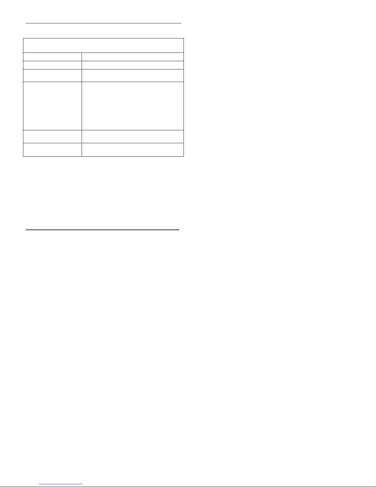
TD. Transmit Data. Lit when modem is transmitting data.
RD. Receive Data. Lit when modem is receivin g data.
CD. Carrier Detect.
LS. Line Status.
TR. Terminal Ready.
PWR. Power.
Lit when data connection has been
established.
Continuous “on”
the wireless modem is not registered
on the network.
Flashing
on network.
Off state
in download mode.
Commonly called “Data Terminal Ready.”
This is a readiness signal from the PC.
Indicates presence of DC power when
lit.
state indicates registration
. Modem is off (not ready) or
state indicates that
21
Page 22
Specifications
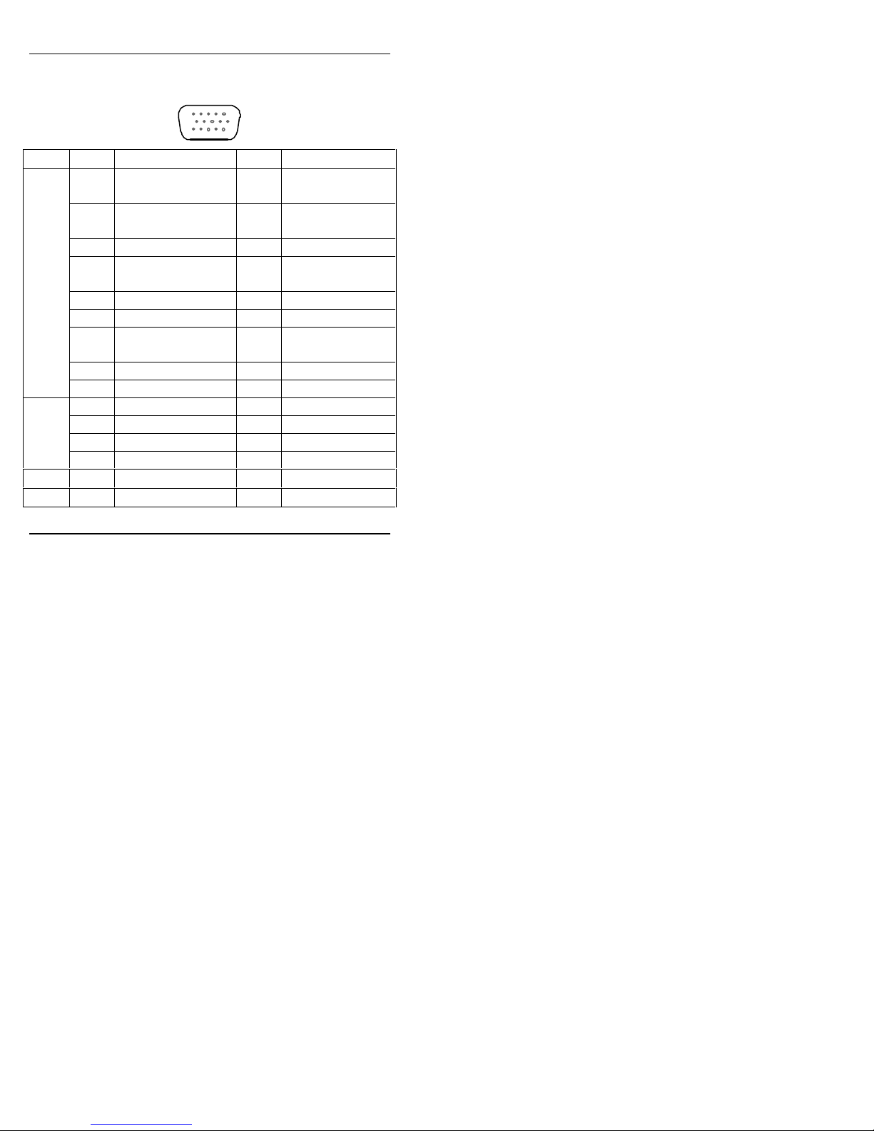
RS232 15-Pin Connector Pinout
PIN EIA CCIT Designation
1 DCD 109 Data Carrier
6 RX 104 Receive Data
2 TX 103 Transmit Dat a
8 DTR 108.2Data Terminal
RS
232
9 GND Signal Ground
7 DSR 107 Data Set Ready
12 RTS 105 Request to
11 CTS 106 Clear to Send
13 RI 125 Ring Indicator
Audio
4 MICROPHONE (+)
5 MICROPHONE (-)
10 SPEAKER (+)
15 SPEAKER (-)
Boot 3 BOOT
Reset 14 RESET
10
15
15
6
11
Direct
(out)
Ready
Send
22
Page 23
Getting Started
Getting Started with your
Wireless MultiModem
Mechanical Mounting
To mount the Wireless MultiModem, do the
following:
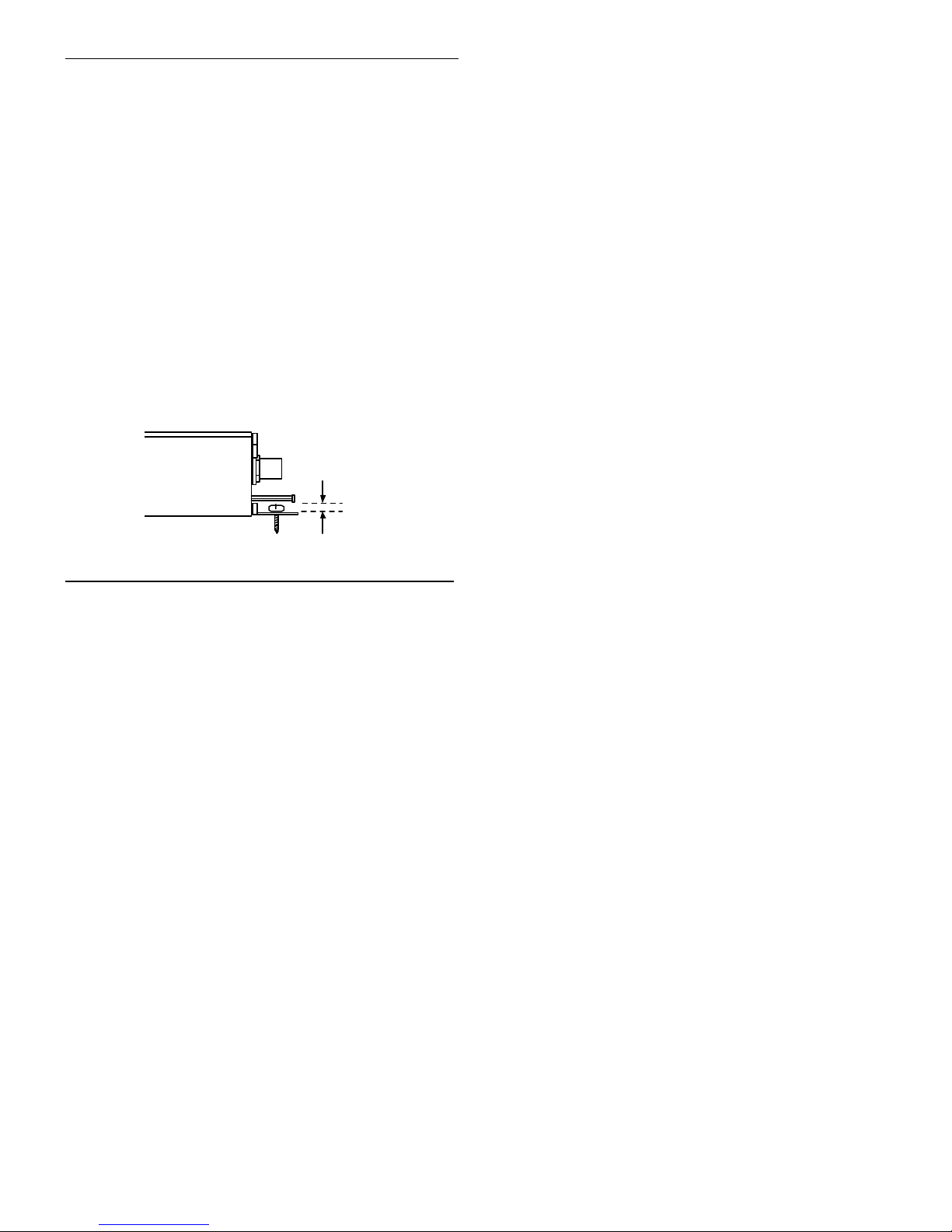
1. Obtain mounting screws (two are needed) that
are appropriate for the surface on which you
will mount the MultiModem. The mounting
screw on the connector end of the unit must
have a screw-head no thicke r than 2 mm. The
allowable thickness is limited because the
screw must fit beneath t he RS232 cable. The
allowable thickness of the other screw-head is
not limited in this way.
Screw Head
Side View
Clearance
= 2 mm
23
Page 24
Getting Started
For example, one might use two 6-32 selftapping screws 5/8” in length to mount the
unit in a truck to the wall of the cab behind the
passenger’s seat.
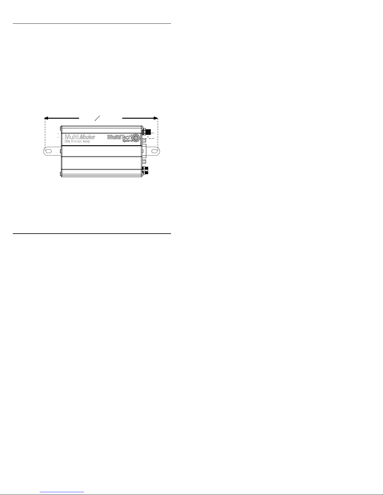
2. Typically, the unit is mounted against a flat
surface into which holes can be drilled. The
mounting holes (center-to-center) must be
separated by 125mm or 4 -15/16 inc hes.
ScrewSeparation
=125mm
15
16
inches
or 4
Drill the mounting holes at the desired
mounting location (if applicable).
24
Page 25
Getting Started
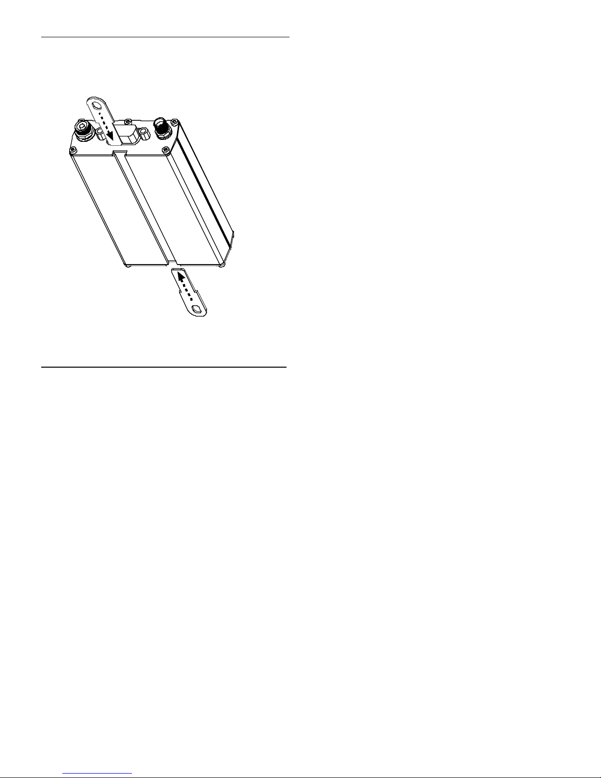
3. Slide the mounting bridles into the
corresponding slots on the back side of the
MultiModem chassis.
4. Attach the MultiModem with two screws to the
mounting surface at the desired location on the
equipment.
25
Page 26
Getting Started
Electrical Installation & Configuration
The wireless MultiModem requires the power
supply connection to begin operation. To install the
modem, do the following:
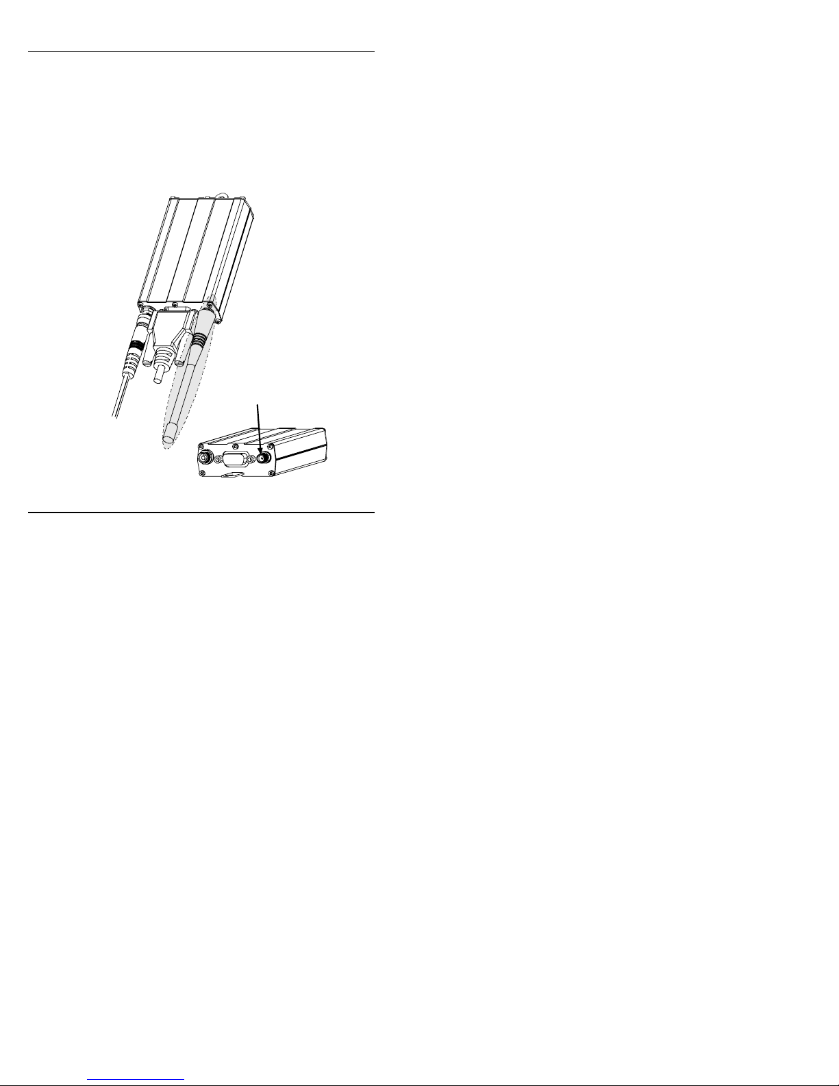
1. Connect a suitable antenna to th e SMA
connector (see specifications on page 8).
Antenna Connector
(SMA type)
26
Page 27
Getting Started
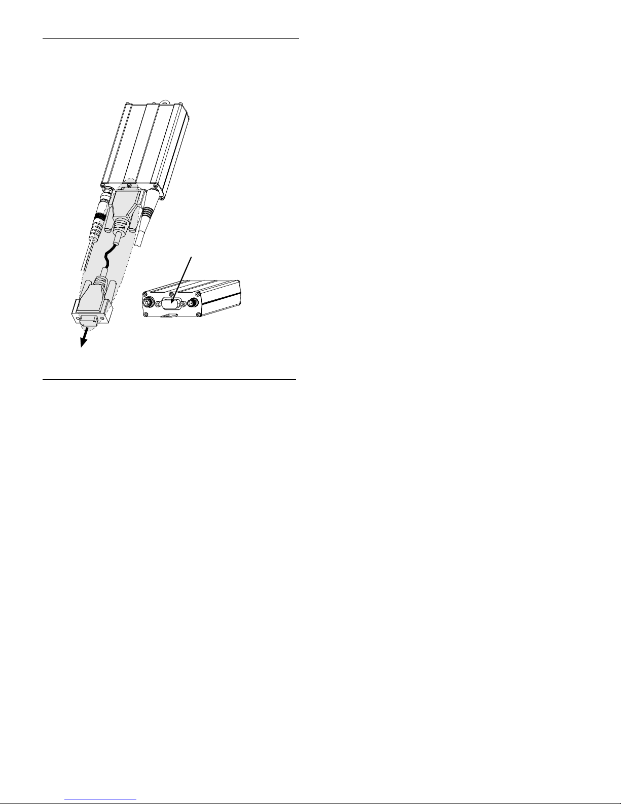
2. Connect both ends of the serial and control
cable (15-pin Sub D connector on the modem
end).
Serial & Control
Connector
To Serial Port
of PC
27
Page 28
Getting Started
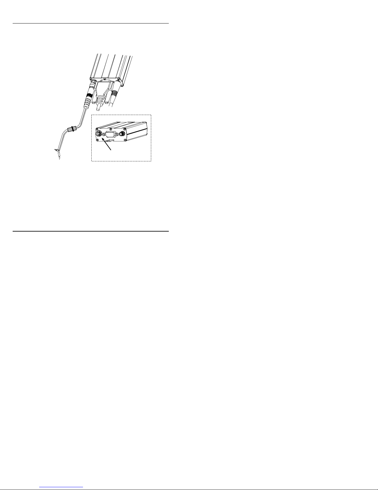
3. Plug the power supply cable into the wireless
Multimodem.
Powe r Co r d
In-Line
Fuse
Power
Connector
To Power Source
4. Connect the power supply cable into the power
supply, with a correct GND connection.
Connect red wire to + (positive) and black wire
to – (negative).
Note: For automotive application: according to the
type of application, you can use permanent
“+” or key-switched “+”.
28
Page 29

Getting Started
Connect the power supply to its source (for
example, in a mobile situation, to the vehicle’s
DC fuse/terminal block).
5. Activate the power supply.
Mobile PhoneTools
For initial configuration of your wireless device,
Multi-Tech offers a Windows
PhoneTools application.
To load mobile PhoneTools, click on the mobile
PhoneTools icon on your system CD and follow the on
screen prompts.
based mobile
29
Page 30
Getting Started
Verifying signal strength
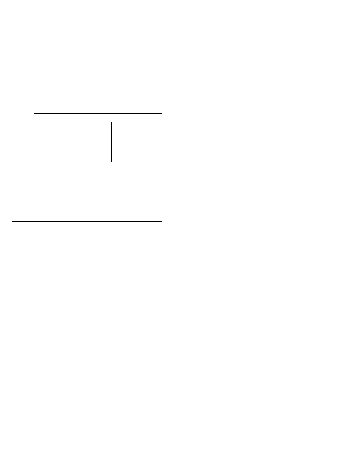
The Wireless MultiModem establishes a call if the
signal is sufficientl y strong. To verify the signal
strength, do the following:
1. Using the Hyperterminal program at the
computer to which the Wireless MultiModem
is connected, type the AT command AT+CSQ.
A value for the received signal strength will be
returned.
2. Verify the result with the following chart:
Signal Strength Verification
Value of signal strength
(AT+CSQ response) (RSSI)
11 - 31 sufficient *
0 - 10 insufficient*
greater than 99 insufficient*
*Based on general observations.
Signal strength
30
Page 31
Getting Started
Verifying network registration
In this procedure, you will verify that the Wireless
MultiModem has been registered on the wireless
network. To do so, you will use the common
communications program
Hyperterminal.
1. Using the
Hyperterminal program at the
computer to which the Wireless MultiModem
is connected, type the AT command
AT+CREG?. A value for the modem’s network
registration status will be returned.
2. Verify the result with the following chart:
Network Registration Verification
Value Network Registration Status
0, 1 Yes
0, 5 Yes
(registered roaming)
Note: If the modem is not registered, perform the
procedure for
Verifying signal strength on
page 32 to determine the strength of the
received signal.
31
Page 32

Getting Started
AT
Commands
Response
Returned
AT+CPIN
=1234
OK
+CME
ERROR : 16
+CME
ERROR : 3
AT +
C
?
CREG =
<
, 1
CREG =
<
, 2
CREG =
<
, 0
Testing the Configuration
Description
Enter
PIN
Code
Module
synchro
checkin
g
REG
mode>
mode>
mode>
Comments
PIN Code accepted
Incorrect PIN Code
PIN already
entered (with
+CMEE : 1 mode)
modem
synchronized on
the network
synchronization
lost, resynchronization
attempt
Modem not
synchronized on
network. No
synchronization
attempt
32
Page 33

Getting Started
AT
Commands
Response
Returned
RING
ATA
OK
A
4;
OK
CME
ERROR : 11
CME
E
: 3
Testing the Configuration (continued)
Description
Receiving
an
incoming
call
Initiate a
call
TD123
RROR
Comments
Answer the call.
Don’t forget the “;”
at the end for
“voice” calls.
Communication
established
PIN Code not
entered (with
+CMEE : 1 mode)
AOC credit (Advice
of Charge tells the
user how much a
call will cost) has
been exceeded or a
communication is
already established.
33
Page 34

Getting Started
AT
Commands
Response
Returned
A
2;
OK
NO
C
R
ATH
OK
AT&W
OK
Testing the Configuration (continued)
Description
Initiate an
emergenc
y call
Communication loss
Hang up
Store the
parameter
s in nonvolatile
memory
TD11
Comments
Don’t forget the “;”
at the end for
“voice” calls.
ARRIE
The
communications
program has saved
the configuration
settings in nonvolatile memory.
34
Page 35

Safety
Troubleshooting
Situation A: The modem does not answer
through the serial link
If the Wireless MultiMod e m do es not answer through the
serial link upon an attempted transmission of data or voice
signals, see the table below for possible causes and solutions.
Solutions for ‘no connection through serial link’
situation
If the
modem
returns
…
(nothing)
Then ask … Action
Is the modem
powered correctly?
Is the serial cable
properly connected to
the modem and PC
sockets?
Provide a power supply in
the range of 5 to 32Vdc.
Connect cable per step 2 of
the ”Electrical Installation
and Configuration”
procedure on page 29.
Verify cable pinout
per”RS232 15-Pin
Connector Pinout” table,
esp Rx & Tx connections.
Verify reception &
transmission.
35
Page 36

Safety
Solutions for ‘no connection through serial link’ situation
(cont’d)
If the
modem
returns …
(nothing)
{cont’d}
Then ask … Action
Is the
communication
program properly
configured?
In communications
program, verify that
modem parameters
have been set to the
values shown here:
Data Bits = 8
Parity = none
Stop Bits = 1
Baud = 115200 bps
Is another program
interfering with the
Close any such
application program.
communication
program?
36
Page 37

Safety
Situation B: The modem always returns
«Error» when trying to issue a
communication
If the Wireless MultiModem returns a message of error upon
an attempted transmission of data or voice signals, see the
table below for possible causes and solutions.
Solutions for “error” message situations
If the modem
Then ask … Action
returns …
error Is the modem
registered on the
network?
Is the modem
receiving an
incoming call or is
it already in
communication?
Does AT+CREG?
return 0,1 (registered)
or 0,5 (registered
roaming)?
37
Follow
network registration”
“Verifying
procedure to be
sure modem is
registered on
network.
End any
communication
using the
ATH
command.
If not, check for
adequate signal
strength on network.
Use AT+CSQ.
Page 38

Safety
Solutions for “error” message situations (cont’d)
If the modem
Then ask … Action
returns …
error
(cont’d)
Is the selected
bearer type
supported by
the called
party?
Is the selected
bearer type
supported by
the network?
Is the received
signal strong
In comm. program,
type AT+CMEE=1 to
view the extended
error codes (see
“Interpretation …” table
below).
Be sure called party
and network support
selected bearer type.
Be sure that semi-
colon (“;”) is typed
immediately after the
phone number in the
AT command. E.g.,
ATD######;
See “Signal Strength
Verification,”
enough?
Is the antenna
properly
connected?
See “Antenna
Specifications,”
8.
Retry.
p 32.
page
38
Page 39
Error
Code
0
3
4
16
26
30
32
40
Safety
Interpretation of Extended Error Codes
related to “error” message
Diagnostic Hint
Phone failure Call technical support
Operatio n not
No action.
allowed
Operatio n not
No action.
supported
Incorrect password Check the code you entered.
Dialing string too long Check the phone number (max.
20 digits).
No network service No action.
Network not allowed –
emergency calls only
Network
personalization PIN
required (Network
lock)
No action.
Enter the Network lock.
Note: Call your network
provider if you do not know
this code.
39
Page 40
Safety
Error
Code
103
106
111
Interpretation of Extended Error Codes
related to “error” message (cont’d)
Diagnostic Hint
Illegal MS (#3)
Illegal MS (#6)
PLMN not allowed
No action.
No action.
No action.
(#11)
112
113
132
Location area not
allowed (#13)
Roaming not allowed
in this location area
(#13)
Service option not
supported (#32).
No action.
No action.
Check the service option.
40
Page 41
Safety
Interpretation of Extended Error Codes
related to “error” message (cont’d)
Error
Code
133
134
149
150
Diagnostic Hint
Requested service
option not subscribed
(#33)
Service option
temporarily out of
order (#34)
PDP authentication
failure
Invalid mobile class Change to valid class.
Call your network provider to
subscribe to the requested
service option.
No action.
Call your network provider to
subscribe to the requested
service option.
For all other codes, and/or details, see AT Commands manual.
41
Page 42

Safety
no carrier
Error Codes” table, page 47).
Situation C: The modem always returns
«No carrier» when trying to
issue a communication
Solutions for “no carrier” message
If the
modem
returns …
(esp. for
data
communication)
Then ask … Action
Is the selected
bearer type
supported by
Type AT+CEER to view the
extended error code (see
“Interpretation of Extended
the called
party?
Is the selected
bearer type
Be sure that the selected
bearer type is supported by
the called party.
Be sure that the selected
bearer type is supported by
the network .
supported by
the network?
If no success, try bearer
selection type:
AT+CBST=0,0,3
42
Page 43

Solutions for “no carrier” message (cont’d)
no carrier
If the
Then ask … Action
modem
returns
Be sure that the
(esp. for
voice
communication)
semicolon character (“;”)
is typed immediately
after the phone number
in the AT command. E.g.,
ATD######;
type AT+CBST=0,0,3
Safety
Is the received
signal strong
enough?
Is the antenna
properly
connected?
See “Signal Strength
Verification,”
See “Antenna
Specifications,”
43
page 32.
page 8.
Page 44

Safety
Safety
General Safety
The modem is designed for and intended to be used in fixed
and mobile applications. “Fixed” means that the device is
physically secured at one location and is not able to be
easily moved to another location. “Mobile” means that the
device is designed to be used in other than fixed locations
and generally in such a way that a separation distance of at
least 20 cm (8 inches) is normally maintained between the
transmitter’s antenna and the body of the user or nearby
persons. The Modem is not designed for or intended to be
used in portable applications (within 20 cm. or 8 in. of the
body of the user) and such uses are strictly prohibited.
44
Page 45

Safety
It is important to follow any special regulations regarding the
use of radio equipment due in particular to the possibility of
radio frequency, RF, interference. Please follow the safety
advice given below carefully.
• Switch OFF your Wireless MultiModem when in an aircraft.
The use of cellular telephones in an aircraft may endanger the
operation of the aircraft, disrupt the cellular network and is
illegal. Failure to observe this instruction may lead to
suspension or denial of cellular telephone services to the
offender, or legal action or both.
• Switch OFF your Wireless MultiModem when around gasoline
or diesel-fuel pumps and before filling your vehicle with fuel.
• Switch OFF your Wireless MultiModem in hospitals and any
other place where medical equipment may be in use.
• Respect restrictions on the use of radio equipment in fuel
depots, chemical plan t s or where blasting operations are in
progress.
• There may be a hazard associated with the operation of your
Wireless MultiModem close to inadequately protected personal
medical devices such as hearing ai ds and pacemakers. Consult
the manufacturers of the medical device t o determine if it is
adequately protected .
• Operation of your Wireless MultiModem close to other
electronic equipment may also cause interference if the
equipment is inadequately protected. Observe any warning signs
and manufacturers’ recommendations.
45
Page 46

Safety
Vehicle Safety
• Do not use your Wireless MultiModem while driving, unless
equipped with a correctly installed vehicle kit allowing ‘HandsFree’Operation.
• Respect national regulations on the use of cellular telephones in
vehicles. Road safety always comes first.
• If incorrectly installed in a vehicle, the operation of Wireless
MultiModem telephone could interfere with the correct
functioning of vehicle electronics. To avoid such problems, be
sure that the installation has been performed by qualified
personnel. Verification of the protection of vehicle electronics
should be part of the installation.
• The use of an alert device to operate a vehicle’s lights or horn
on public roads is not permitted.
Maintenance of Your Modem
Your Wireless MultiModem is the product of advanced
engineering, design and craftsmanship and should be treated
with care. The suggestions below will help you to enjoy this
product for many years.
• Do not expose the Wireless MultiModem to any extreme
environment where the temperatu r e or humidity is high.
• Do not attempt to disassemble the Wireless MultiModem. There
are no user serviceable parts insi de.
46
Page 47

Safety
• Do not expose the Wireless MultiModem to water, rain or spilt
beverages. It is not waterproof.
• Do not abuse your Wireless MultiModem by dropping,
knocking, or violently shaking it. Rough handling can damage
it.
• Do not place the Wireless MultiModem alongside computer
discs, credit or travel cards, or other magnetic media. The
information contained on discs or cards may be affected by the
phone.
• The use of accessories not authorized by Multi-Tech o r not
compliant with Multi-Tech’s accessory specifications may
invalidate the warranty of the Wireless MultiModem.
• In the unlikely event of a fault in the Wireless MultiModem,
contact Multi-Tech’s Tech Support.
Your Responsibility
This Wireless MultiModem is your responsibility. Please treat
it with care respecting all local regulations. It is not a toy.
Therefore, keep it in a safe place at all times and out of the
reach of children.
Try to remember your Unlock and PIN codes. Become
familiar with and use the security features to block
unauthorized use and theft.
47
Page 48

Warranty & Repair
Warranty & Repairs Policies
Warranty
Multi-Tech Systems, Inc., (hereafter “MTS”) warrants that its
products will be free from defects in material or workmanship
for a period of two years from date of purchase, or if proof of
purchase is not provided, two from date of shipment.
MTS MAKES NO OTHER WARRANTY, EXPRESS OR
IMPLIED, AND ALL IMPLIED WARRANTIES OF
MERCHANTABILITY AND FITNESS FOR A PARTICULAR
PURPOSE ARE HEREBY DISCLAIMED.
This warranty does not apply to any products which have
been damaged by lightning storms, water, or power surges or
which have been neglected, altered, abused, used for a
purpose other than the one for which they were
manufactured, repaired by Customer or any party without
MTS’s written authorization, or used in any manner
inconsistent with MTS’s instructions.
MTS’s entire obligation under this warranty shall be limited
(at MTS’s option) to repair or replacement of any products
which prove to be defective within the warranty period or, at
MTS’s option, issuance of a refund of the purchase price.
Defective products must be returned by Customer to MTS’s
factory – transportation prepaid.
48
Page 49

Warranty & Repair
MTS WILL NOT BE LIABLE FOR CONSEQUENTIAL
DAMAGES, AND UNDER NO CIRCUMSTANCES WILL ITS
LIABILITY EXCEED THE PRICE FOR DEFECTIVE
PRODUCTS.
Repairs
Repair Procedures for U.S. and Canadian
Customers
In the event that service is required, products may be shipped,
freight prepaid, to our Mounds View, Minnesota factory:
Multi-Tech Systems, Inc.
2205 Woodale Driv e
Mounds View, MN 55112
Attn: Repairs, Serial # ____________
A Returned Material s Authorization (RMA) is not required .
Return shipping charges (surface) will be paid by MTS.
Please include, inside the shipping box, a description of the
problem, a return shipping address (must have street address,
not P.O. Box), your telephone number, and if the product is
out of warranty, a check or purchase order for repair charges.
49
Page 50

Warranty & Repair
For out of warranty repair charges, go to
www.multitech.com/documents/warranties
Extended two-year overnight replacement service agreements
are available for selected products. Please call MTS at (888)
288-5470, extension 5308 or visit our web site at
http://www.multitech.com/programs/orc/ for details on
rates and coverages.
Please direct your questions regarding technical matters,
product configuration, verification that the product is
defective, etc., to our Technical Support department at (800)
972-2439 or email [email protected]. Ple ase direct your
questions regarding repair expediting, receiving, shipping,
billing, etc., to our Repair Accounting department at (800) 3289717 or (763) 717-5631, or email mtsrepair@mul titech.com.
Repairs for damages caused by lightning storms, water, power
surges, incorrect installation, physical abuse, or user-caused
damages are billed on a time-plus-materials basis.
50
Page 51

Warranty & Repair
Repair Procedures for International Customers
(Outside U.S.A. and Canada)
Your original point of purchase Reseller may offer the quickest
and most economical repair option for your Multi-Tech
product. You may also contact any Multi-Tech sales office for
information about the nearest distributor or other repair
service for your Multi-Tech product.
http://www.multitech.com/COMPANY/offices/DEFAULT.ASP
In the event that factory service is required, products may be
shipped, freight prepaid to our Mounds View, Minnesota
factory. Recommended international shipment methods are
via Federal Express, UPS or DHL courier services, or by
airmail parcel post; shipments made by any other method will
be refused. A Returned Materials Authorization (RMA) is
required for products shipped from outside the U.S.A. and
Canada. Please contact us f or return authori zation and
shipping instructions on any International shipments to the
U.S.A. Please include, inside the shipping box, a description
of the problem, a return shipping address (must have street
address, not P.O. Box), your telephone number, and if the
product is out of warranty, a check drawn on a U.S. bank or
your company’s purchase order for repair charges. Repaired
units shall be shipped freight collect, unless other
arrangements are made in advance.
51
Page 52

Warranty & Repair
Please direct your questions regarding technical matters,
product configuration, verification that the product is
defective, etc., to our Technical Support department nearest
you or email [email protected]. When calling the U.S.,
please direct your questions regarding repair expediting,
receiving, shipping, billing, etc., to our Repair Accounting
department at
+(763) 717-5631 in the U.S. A., or email
[email protected].
Repairs for damages caused by lightning storms, water, power
surges, incorrect installation, physical abuse, or user-caused
damages are billed on a time-plus-materials basis.
Repair Procedures for Internationa l Distributors
Procedures for International Distributors of Multi-Tech
products are on the distributor web site.
http://www.multitech.com/PARTNERS/login/
52
Page 53

Reference Info
Wireless Modem Reference Info
Reference Documents: AT Commands CDMA Reference Guide
S000294A
ETSI contact : ETSI Secretariat
F-06921 Sophia Antipolis Cedex,
France
e-mail : [email protected]
Service : The AT commands manual is available
on the MultiTech web site:
http://www.multitech.com
Disclaimer
Wireless MultiModem specifications and manuals are subject
to change without notice. MTS assumes no liability for
damage incurred directly or indirectly from errors, omissions
or discrepancies between the Wireless MultiModem and its
manuals.
53
Page 54

82001130
 Loading...