

Page 1
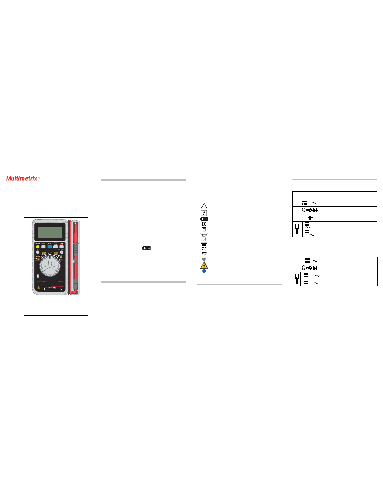
DMM 16
Multimeter
User’s manual
CHAUVIN ARNOUX
190, rue Championnet
75876 PARIS Ced ex 18 - FRANCE
Tel.: +33 1 44 85 44 8 5 - Fax: +33 1 46 27 73 89
info@chau vin-arnou x.fr
Export: Tel.: +33 1 44 85 44 3 8 -Fax: +33 1 46 27 95 59
export@chauvin-arnoux.fr
694243A02 - Ed. 4 - 07/14
PRECAUTIONS F OR USE
This device is compliant with safety standards IEC61010-1, 61010-2-032 and 61010-2-033 for
voltages up to 300V in category III at an altitude below 2,000m, indoors, with a degree of pollution
of not more than 2.
These safety instructions are intended to ensure the safety of persons and proper
operat ion of the dev ice. If t he device is used othe r than as spec ified in t his data s he et, the
protec tion provided by the de vice may be i mpaired.
The opera tor and/o r the res po nsible aut ho rity must carefully read and c learly
underst and the va rious prec autions to be taken i n use.
If you use this ins t rument othe r than as s pe cified, t he protec tion it prov ides may be
compromi s ed, ther eby endanger ing you.
Do not use the instrument in an explosive atmosphere or in the presence o f
flammable gases or fumes.
Do not use the instrument on networks of which the voltage or category exceeds
those mentioned.
Do not exceed the rated maximum voltages between terminals or with respect to
earth.
Do not us e the instrument if it seems to be damaged, incomplete, or poorly closed.
Before eac h use, c hec k the co nditi on o f the ins ulatio n on t he le ads , hous ing, a nd
accesso ri es. Any ite m of whi ch t he i nsula ti on is dete rio rate d (e ven pa rti ally ) must
be set aside for repair or scrapping.
Use leads and accessories rated for voltages and categories at least equal to
those of the instrument. If not, an accessory of a lower category reduces the
category of the combined multimeter + accessory to that of the accessory.
Observe the environmental conditions of use.
Do not modify the instrument and do not replace components with "equivalents".
Repair s and adjust me nt s must be done by appr o ved quali f ied pers onnel.
Replace the battery as soon as the
symbo l appe ars on t he dis play unit .
Disconne ct all leads before opening the battery compartment cover.
Use pers onal protec tive equipment when co nditions require .
Keep your hands awa y from the unus ed test pr obes of the device.
When handli ng the te st probes, crocodile clips, and c urrent sens or, keep yo ur
fingers behind the p hysica l gua rd.
Disconnect the test probes from the measurement circuit to make current
measurements.
Disconnect the test probes from the measurement circuit before changing
functio ns.
MEASUREMENT CATEGORIES
CAT II: Circuits directly conne cted to the low-voltage insta llation.
Example: power supply to electro -do mestic dev ices and por table tools.
CAT III: Po wer supply c ircuits in the installation o f the building.
Example: distributio n panel, ci rcuit-bre a kers, mac hi nes or fixe d industri al devices.
CAT IV: Circuits supply ing the low -v oltage i nstalla t ion of the building.
Example: power feeders, counters and protection devic es.
- 1 -
You have just acquir ed a DMM16 multi meter a nd we thank you for your confidenc e.
For best results f r om your ins trument:
Read t hes e operati ng instruc tions car efully;
Comply wit h t he preca utions fo r use.
Risk of danger. The operator agrees to refer to these instructions
wheneve r this danger symbol appe ars.
Applica tion or wit hdrawal aut horized on uninsulat ed or bare conducto rs at
dangerous voltage s.
Battery
The CE marki ng indic a tes conf o rmity wi th Europea n directiv es.
Double ins ulatio n or reinfo rced insula tion.
Select ive sorti ng of wastes f or the rec y c ling of e le ctrical a nd electro nic
equipment w ithin the E uropean Union. In c onformit y with dire ctive WE EE
2002/96 /EC: this equipment mus t not be t reated as household w a ste.
DC– Direct current
AC– Alter nating cur r ent
AC and DC– Alt e rnating a nd direc t current
Earth
Risk of e lectric s hock
Instruc tions tha t must be read and unders t ood
1. PRESENTATION
Le DMM16 is an ins trume nt fo r mea suri ng ele ct ri cal qua ntit ie s tha t gro ups t he f ollow ing
functio ns:
AC or DC voltage measurement;
Frequency measurement;
Resistance measurement, continuity measurement with buzzer, or diode test;
Capacitance measurement;
DC or AC current measurement;
- 2 -
1.1 The switch
The swit ch has six pos itions. To access the v arious functio ns, set the s witch t o the
corres ponding posi tions. E ach active position is confirmed by an audible s ignal. The
functio ns are desc ribed in t he table belo w.
OFF Stop
V or V /Hz
AC or DC voltage measurement/Frequency
measurement
/ /
Resistance measurement, continuity
measureme nt with buzzer, or diode test
Capacitance measurement
120A/
120A/Hz
120A DC or AC current measurement/
Frequency measurement
60A
/
60A/Hz
66A DC or AC current measurement/
Frequency measurement
1.2 The keys of the keypad
-"SEL" (SELECT) key
Press the "SEL" key repeatedly to obtain the following functions according to the setting
of the rotary switch:
V
/V
DC voltage/AC voltage
/ /
Resistance measurement/continuity
measurement/diode test
120A/ 120A
120A DC current measurement/120A AC current
measurement
60A/ 60A
66A DC current measurement/66A AC current
measurement
-"RANGE" key
Your multimeter ha s a range change f unction t hat is no rmally aut omatic but can be made
manual. W hen the inst rument is s witched on, t he default mo de is automa tic range
change: t he "AUTO" mes s age is t he n display ed.
Brief ly press the "RANGE" key t o change t o manual mode: the "AUTO" message is
then repla ced by "MANU".
Succes s i ve brief presses are used to reach the desi red range.
Hold the "RANGE" key down for 2 seconds to return to the automatic range change
mode: the "MANU" message reverts to "AUTO".
- 3 -
Page 2

Choice of ranges (o r ratings) a ccording t o functio n:
660.0mV/6. 600V/66.00V/600.0V
660.0mV/6. 600V/66.00V/600.0V
Ω
660.0Ω
6.600kΩ/ 66.00kΩ/660.0kΩ
6.600MΩ/ 66.00MΩ
6.600nF/66.00nF /660.0nF
6.600μF/66.00μF/660.0μF/6.600 mF/66.00mF
-"HOLD " key
In the "HOLD" mode, the device freezes the display of the last value measured.
Pressi ng the "HOLD" ke y brief ly during a me a surement freezes the display: the
message
is the n di splayed.
A second brief press on the "HOLD" key is used to return to the normal measured
value di s play refr esh mode: the messa ge
disappears from the di splay uni t .
-"MAX MIN" key
In the "MAX MI N" mode, the device records the maximum and minimum values of the
measurements made. In this mode , the auto matic range change does not c hange the
range when this mode is entered; if the maximum values exceed the display range
(indicated by the "OL" message), the appropriate hi ghe r r a nge must be c ho s e n manua l ly
before reactivating the "MAX MIN" mode.
Succes s i ve brief presses on t he "MAX MIN" ke y produce , in orde r , the follo w ing actio ns:
1st press : the device re cords and displa ys the maximum va lue measured. The
"AUTO" message is replaced by "MANU" and the "MAX" message is displayed.
2nd pres s : the de vi ce r ec o rds a nd di s pla y s the mini mum value mea s ure d; the " M AX "
message is replace d by "MIN".
3rd press: the device records the maximum and minimum values measured
simultaneously; it is the va lue curr ently meas ured tha t is displa yed; the "MAX" and
"MIN" mes s ages blink s imultane ously on the display unit.
Additio nal press es serve to display the values rec orded one by one by re producing t he
actions of the prev ious succ essive pres ses.
Press the "MAX MIN" key for two seconds to exit from the mode: the "MANU", "MAX",
and "MIN" messages are replaced by "AUTO", indicating that the device once again
changes range auto matically.
-"Hz" ( Hertz ) key
Press the "Hz" key briefly and repeatedly to obta in t he fo llow ing func ti ons acco rdi ng to
the setting of the rotary switch:
AC volta ge measured/ Frequenc y/Duty c y c le
DC volta ge measure d/Frequenc y/Duty c y c le
- 4 -
120
120A AC cur rent meas ured/Fre quency/Duty cycle
60
66A AC current measure d/Frequency/Duty c y cle
NB: When the duty cycle measurement is activated, the automatic range change leaves
the range unchange d when t he mode is ent ered: the devi ce change s to manua l range
change mode and the "M ANU" messa ge is dis played.
- "
" (Backligh t) key
A brief pre s s o n the "B a c kli g ht" k ey li g ht s o r s w it c he s o ff t he di s pla y uni t ba c kli ghting. If
not reactivated, the backlighting switches itself off automatically after approximately 60
seconds .
"REL (ZERO)" key
The "REL (ZERO)" key is used to subtract the value displayed when the key is pressed
from all su bsequent measureme nt values a nd display the res ult of the subt raction.
This mode can be activated by a brief press on the key for all functions except the
frequenc y and duty c ycle meas urements.
When dis play in re lative mode is activate d, the auto matic range cha nge leav es the range
unchanged when the mode is entered: the device changes to manual range change
mode and the "MANU" and "
" messa ges are displa yed.
For DC current measurements, this mode is used to set the display to zero before the
current senso r is pla ced on t he conduc tor in whic h the c urrent is to be measur ed; the
message displaye d for this function, i n this mode, i s "ZERO".
Another brief press on the key effects the return to the normal displa y mode ; the dev ic e
returns to t he a uto mat i c ra nge c ha nge mo de and t he "MAN U" a nd "
" messages are
replaced by the "AUTO" message.
Any change o f functi on by the r otary swit ch terminat es displa y in the re lative mode.
1.3 The display unit
- 5 -
Symbol
Description
AUTO
Automati c range c hange
MANU
Manual ran ge change
(Data Hold) Freezes the display
Value dis played in r elative mode
Display of the maximum and minimum values
ZERO
Reset for DC current measurements
Diode test function
Continuity test function
%
Unit and f unc tion Duty cycle
APO
(Auto Power Off) automatic s w itching of f activa ted
DC measurement and display
AC measurement and display
Display of a negati ve value
Low battery indicator (battery must be replaced)
V
(Volt) unit of voltage
A
(Ampere) unit of current
(milliFarad, nanoFarad, microFarad) units of capacit ance
(ohm, kilo-ohm, Megohm) unit of resistance
Hz
(Hertz) unit of f requency
The "OL" message (OverLoad) indicates an overshoot of the measurement or display
capacity.
1.4 The leads and t est pr ob es
The multimeter is equipped with two leads (red and black), each terminated by a test
probe of the same colour.
The leads and test probes are not detachable (they are permanently connected) and,
when not i n us e, c a n be s to we d i n the c o mpar tme nts pr o v i ded f o r t he m on t he ri g ht s ide
of the dev ice.
The tips of the test probes (once taken out of their compartments by pressing on them
with a finger), allow volta ge, resi stance, continuit y, diode test, and c apacita nce
measurements.
The test probes have physical guards that show the operator where the hand grip part
ends, bey ond which t he fingers must not be placed.
1.5 The current sensor
The multimeter has a current sensor that makes it possible to measure a current without
having to open the ci rcuit.
The curre nt s ens or a nd it s le ad c anno t be de ta che d (the y ar e pe rmanent ly c onne ct ed) ;
when not in us e , t hey c a n be s t o wed i n c o mpa rt ments pro v i de d fo r the m on the ba c k o f
the devic e.
The curre nt sens or has a physic al guard that shows the operator where the hand grip
part ends , beyond w hi ch the fi ngers must no t be plac e d.
- 6 -
2. US E
2.1 Commissioning
Place t he batterie s supplied wi th the dev ice as follo ws:
1. Using a cross-headed screwdriver, unscrew the screw of the compartment cover
on the bac k of the hous ing and open t he cover;
2. Place the 2 batteries in their compartment, with the correct polarities;
3. Clo se the cov er and scre w it back t o t he housi ng.
2.2 Starting up and check of operation
We reco mmend perfo rming this procedure at the t ime of commi s sioni ng and, if the devic e
is used only occasio nally, e ac h time it is used.
Hold the " HOLD" key down and s w itch the instrument o n by turni ng the switch fro m
"OFF" to "Ω".
Release the "Hold" key and check that the various symbols and segments are
correc tly display ed.
A brief press on the "HOLD" key restores the normal display of the selected
functio n;
If the device is set to the resistance measurement function ("Ω"), che ck tha t the
display indicates "A.P.O" (for auto power off), "AUTO" (for automatic range
change), "O.L" (for OverLoad), and "MΩ" (for Megohm);
Withdraw the two leads from their compartment and establish a good contact
between the metallic parts of the two test probes; the value measured and
displayed must cha nge from "O.LMΩ" to "0.0Ω": (the va lue display ed may not
be exactly zero, but must remain very close to zero).
The instrument is operational when the various states described above have been
checke d and are co rre c t. The r ot a ry s witc h c a n t hen be s et t o the de si r ed f unc t i on
or to "OFF" to switch the instrument off.
- 7 -
Page 3

2.3 Deactivating Auto Power Off
In order to ext end t he li fe of t he ba tter ies , the devic e swi tche s its elf off aut omat ica lly
approxi mately 15 minutes after it is switched on if no key or change of function has
been activated. The devi ce warns that it i s about t o switc h off by e mitting 3 s eries o f 2
audible be eps and, i f no actio n is take n, then emits a long beep and s witche s itself of f.
When the multimeter switches itself off automatically, it can be restarted in the same
configur a t io n by pr e s si ng the " HOL D" ke y t wi c e. Any o the r ac t io n r es ta r ts t he de vi ce ,
but changes its configurati on.
Automati c swi tching o ff ca n be deac tivat ed by ho lding down t he "Hz", "REL", "MAX
MIN", "R ANGE " or "B a c kli ght " ke y w hi le s w i tc hi ng o n. Reminder : a ut o matic s wi tc hi ng
off is de activate d when the instrument is in the "MAX MI N" mode.
To elimina te the sli ght re si dual drai n of the ba tte ri es i n the s lee p mode , i t i s alw ays
best to s witch the device "OF F ".
2.4 DC current measurement (A
)
For optimum safety, current measurements on circuits at voltages between 300V and
600V must be made only on category III installa t i ons o r on c i rcui t s of whi c h t he pos s i ble
overvo ltage leve ls are known t o be less t han those o f category III.
The current senso r must not be used at the s a me time as the test pro bes.
The instrument has 2 measurement ranges, selected using the rotary switch (60A and
120A).
Remove the current sensor from its compartment on the back of the device (the test
probes a re stowed i n their ow n compartment.
Switch the instrument on in the 60A or 120A setting.
Let the va lue dis playe d stabi lize and brief ly pre ss the "REL (Z ERO)" ke y to set the
value displayed to zero. It is often necessary to repeat this operation after measuring
strong c urrents .
Place t he se ns o r on t he ca ble as i ndic at e d by the locati ng mar ks (t he s e nso r must be
perpendic ular to the cable on which it is placed), see the figure below.
Read the measurement result (after stabilization).
Display of the "-" s i gn in front of the nu me r ical va lue indicates tha t the value me a sured
is nega tive: the cur rent is f lowing i n the dire ct ion o ppos it e the po lar itie s indi ca ted o n
the sensor.
Note: best result s are obta ined when t he cable i s carefully c entred a nd any near by cables
are held away from it.
- 8 -
2.5 AC current measurement (A
)
For optimum safety, current measurements on circuits at voltages between 300V and
600V must be made only on category III installa t i ons o r on c i rcui t s of whi c h t he po s s i ble
overvoltage levels are known to be less than those of category III. The c urre nt s ens or
must not be used at the same time as the test probes. The instrument has 2
measurement ranges, selected using the rotary switch (60A and 120A).
Remove the current sensor from its compartment on the back of the device (the test
probes are stowed in their own compartment.
Switch the instrument on in the 60A or 120A setting.
Press the "SEL" key briefly to switch to AC current measurement; the "
" symbol is
displayed instead of "
";
Place t he se ns o r on t he ca ble as indi c at e d by t he loc at i ng mar ks (t he s e nso r mus t be
perpendic ular to the cable on which it is placed), se e the figur e above.
Read the measurement result (after stabilization).
Note: be s t results are obta ined when the cable i s carefully c entred a nd any near by cables
are held away from it.
2.6 DC voltage me asurement (V
)
For optimum safety, current measurements on circuits at voltages between 300V and
600V must be made only on category III installa t i ons o r on c i rcui t s of whi c h t he po s s i ble
overvoltage levels are known to be less than those of category III. The ins t rument ha s 4
measurement ranges: 660mV, 6,6V, 66V, 600V. The 600 mV ra nge c an be use d only in
the manual range change mode, by repeated presses on the "RANGE" key. The other
ranges can be used in either the manual or the automatic range change mode.
Withdraw the test probes and le ads fro m the ir compart ment.
Switc h t he instrument on in the " V" sett ing.
Apply the meta llic part of the bla ck t est pr obe on t he (ass umed) ne ga ti ve pa rt of the
circuit to be teste d.
Apply the metallic part of the red test pr obe on the (assumed) pos itive part of the
circuit to be teste d.
Read the measurement result (after stabilization).
Display of the "-" s i gn in front of the nu me r ical va lue indicates tha t the value me a sured
is negative (the test probes are reversed with respect to the polarity of the voltage).
2.7 AC voltage me asurement (V
)
For optimum safety, current measurements on circuits at voltages between 300V and
600V must be made only on category III installa t i ons o r on c i rcui t s of whi c h t he po s s i ble
overvoltage levels are known to be less than those of cat. III. The DMM16 has 4
measurement ranges: 660mV, 6,6V, 66V, 600V.
The 600mV ra nge ca n be used only in the manua l range cha nge mode, by repe ated
presses on the "RANGE" key. The other ranges can be used in either the manual or the
automatic range change mode.
Withdraw the test probes and le ads fro m the ir compart ment.
Switc h t he instrument on in the " V" setti ng.
Press the "SEL" key briefly to switch to AC voltage measurement (the "
" symbol is
displayed instead of "
")
Apply the metallic part of the black test probe on the part of the circuit to be tested
(assumed) closest to the earth potential.
Apply the metallic part of the red test probe on the part of the circuit to be tested
(assumed) farthest from the earth potential.
Read the measurement result (after stab il ization).
- 9 -
2.8 Frequency measurement (Hz)
For optimum safety, current measurements on circuits at voltages between 300V and
600V must be made only on category III installa t i ons o r on c i rcui t s of whi c h t he po s s i ble
overvoltage le vels are kno wn to be le ss than tho se of cate gory III.
The instrument has 3 measurement ranges: 660,0Hz, 6,600kHz and 66,00kHz.
Measurement of t he frequency of the voltage measured: start the AC voltage
measurement method, then press the "Hz" key (display of the "Hz" symbo l instea d of "V").
Measure ment of the f requenc y of the curr ent be ing mea sured: star t the AC c urre nt
measureme nt met ho d, t hen pre s s the " H z" ke y ( the " H z" s y mbo l i s dis pla y e d i ns t e ad
of "A";
Read the measurement result after stabilization.
2.9 Duty cycle measurement (%)
For optimum safety, current measurements on circuits at voltages between 300V and
600V must be made only on category III installa t i ons o r on c i rcui t s of whi c h t he po s s i ble
overvoltage level s are known to be less tha n t hose of cat egory III.
The measurement range is from 10% to 94.9% (50-60Hz). If there is no usable signal or if
the duty c ycle is less tha n 10%, the display i ndicates "UL", and if the duty cycle is great e r
than 94. 9%, the dis play indicates "OL".
For volt age duty cycle meas urements , the de vice swi tches its elf to t he manual ran ge
change mode.
Measurement of the duty cycle of the voltage being measured: start the AC voltage
measureme nt method, then pre ss the " Hz" key twi ce (the "%" symbol is displaye d
instea d of "V" and "MANU" instead of "AUTO") ;
Measure ment of the dut y cycle of the c urrent being mea sured: star t the AC c urre nt
measureme nt method, then pres s "Hz" twic e ("%" is di splayed instead of "A");
Read the measurement result after stabilization.
2.10 Resi stance measureme nt (Ω)
Resista nce, co ntinuit y, diode test, and capac itance measure ments must be made
only on circuits completely disconnected from any power supply, and after any capacitors
have be e n discharge d.
The instrument has 6 measurement ranges: 660,0Ω, 6,600kΩ, 66,00kΩ, 660,0kΩ,
6,600MΩ and 66,00MΩ.
All of the ranges can be used wi t h either automatic or manual range change.
Withdraw the test probes and le ads fro m the ir compart ment.
Switc h t he instrument on in the "Ω " setting.
Apply the metallic tips of the test probes to the terminals of the resistance or of the
circuit to be teste d
Read the measurement result (after stabilization).
NB: Touching the elements or circuit during the measurement may lead to erroneous
results . For res istance measurements on nonlinear circuits, it may be necessary to select
the measurement mode and the range to be used manually.
- 10 -
2.11 Continuity measurement (Ω)
Resista nce, co ntinuit y, diode test, and capac itance measure ments must be made
only on circuits completely disconnected from any power supply, and after any capacitors
have be e n discharge d.
The instr ument in dicates continuity by emitt ing a ste ady sound w hen the r esista nce
measured is less tha n 50Ω.
The value di splayed is the va lue measure d in ohms.
Withdraw the test probes and le ads fro m the ir compart ment.
Switch the instrument on in the "Ω" setting.
Press t he "SEL" key briefly unt il "
" appears.
Apply the metallic tips of the test probes to the terminals of the resistance or of the
circuit to be teste d.
Read (if necessary) the measurement result (after stabilization).
2.12 Diode measurement (Ω)
Resistance, continuity, di ode tes t, and ca pacitanc e meas urements must be ma de
only on circuits completely disconnected from any power supply, and after any capacitors
have be e n discharge d.
The instr ument indi cates the voltage ac ross the t erminals o f the semico nducting ju nction.
Take out t he test pr o bes and lea ds .
Switc h t he instrument on in the "Ω" setting.
Press t he "SEL" key briefly until the "
" symbol appears
Apply the metallic tips of the test probes to the terminals of the diode or of the junction
to be tes ted, accor ding to the following po lariti e s;
1) for wa rd directi on (conduct ing): apply the blac k probe to the catho de and the red
probe to the anode. Read the measurement result (after stabilization), see figure A
(the thre shold voltage of a s i licon dio de is betwee n 0.5V and 0.7 V; it is be tween 0.2
and 0.3V for a germanium diode. High-voltage diodes, some Zener diodes, and LEDs
cannot be tested by t his metho d) .
2) reverse direction (non-conduct ing): apply the black probe to t he anode and t he red
probe to the cathode. Read the measurement result (after stabilization), see figure B
(a diode or junction in good c onditio n causes t he display of "OL").
With some t ypes of di ode , a meas ured v alue o uts ide t he sta ted v olta ge ra nges does
not neces sarily me a n that the diode or junc tion is de fective .
3. CHARACTER ISTICS
3.1 General conditions
Temperature
23°C ± 2°C
Relative humidity
45% to 75%
Supply vo ltage
2,8V ± 0.3V
Frequenc y range o f the applie d s ignal
45-65Hz
Sine wave
pure
Peak fac tor of the a pplied AC si gnal
√2
Positi on of the conduct or in the senso r
centred
Adjacent conducto rs
none
AC magnetic field
none
Electric field
none
- 11 -
Page 4

3.2 Characteristics under the conditions of use
Display rate: approximately 3 measurements per second
The uncertainti es are expressed in ± (x% L+y digi t)
DC current measurement
Range
Resolution
Measurement uncertainties
Input resistance
66.00A
0.01A
2.0% +10
─
120.0A
0.1A
2.0% +5
AC current measurement
Range Resolution
Measurement uncertainties
Input resistance
45~400Hz
66.00A
0.01A
2.0% +5 ─
120.0A
0.1A
DC voltage measur em ent
Range
Resolution
Measurement uncertainties
Input resistance
660.0mV
0.1mV
1.0% +3 approx. 10MΩ
6.600V
0.001V
66.00V
0.01V
600.0V
0.1V
AC voltage measur em ent
Range Resolution
Measurement uncertainties
Input resistance
45~60Hz
60~400Hz
660.0mV
0.1mV
1.5% +5
-
approx. 10MΩ
6.600V
0.001V
1.5% +5
66.00V
0.01V
600.0V
0.1V
Resistance measu r ement
Range Resolution
Measurement
uncertainties
Voltage
maximum
applic able
660.0Ω
0.1Ω
1.0% +5
600V
6.600kΩ
0.001kΩ
66.00kΩ
0.01kΩ
660.0kΩ
0.1kΩ
6.600MΩ
0.001MΩ
2.0% +5
66.00MΩ
0.01MΩ
3.0% +5
Continuity measurement
Range
Resolution
Observation No-load voltage
660.0Ω 0.1Ω
The buzzer is
actuated at values
less t ha n
approximately 50Ω
approx. 0.8V
- 12 -
Diode test
Range
Resolution
Measurement uncertainties
No-load voltage
2.000V
0.001V
1.0%+5
approx. 2.0V
Capacitance me asurement
Range
Resolution
Measurement uncertainties
Remarks
6.600nF
0.001nF
2.5% +5
after adjustment of the
zero for the ranges from
6.6nF to 6.6µF
66.00nF
0.01nF
660.0nF
0.1nF
6.600μF
0.001μF
66.00μF
0.01μF
660.0μF
0.1μF
6.600mF
0.001mF
3.0% +5
66.00mF
0.01mF
Frequency measurement
Range Resolution
Measurement uncertainties
Remarks
10.0~660.0Hz
0.1Hz
0.1% +5
At values <10.0Hz,
the displa y indicates
00.0Hz
6.600kHz 0.001kHz
0.1% +3
66.00kHz 0.01kHz
Sensitivity
Range
Minimum input signal (sine wave)
10Hz~400Hz
400.1Hz~10.00kHz
660mV
200mV
400mV
6.6V 0.3V 0.7V
66V
1V
3V
660V
10V
20V
66A 1A 6A
120A 10A 50A
Duty cycle measurement
Range Resolution
Measurement
uncertainties
Remarks
10% ~
94.9%
0.1%
0.5% +5
no signa l o r a cycle le ss than 10 %
causes the display of "UL";
A cycle greater than 94.9%, causes
the displa y of "OL ".
For a square wave at 50/60Hz
- 13 -
3.3 Environmental conditions
Environmental conditions in use in storage
Temperature
0°C to +50°C
32°F ~ 122°F
-10°C to +60°C
14°F~140°F
Relative humidity (RH)
≤80% without
condensation
≤70% without
condensation
Altitude <2.000m up to 10.000m
3.4 Constructive characteristics
Housing Rigid po ly carbona te shell wi th moulded e lastomer coveri ng
Sensor Polycar bonate Clamping diameter: 12mm
Screen LCD di splay unit with blue ba cklighti ng
Dimensions: l 41xH 18mm
Dimensions H 130xL 81xP 24mm
Weight 160 g (without batt ery)
3.5 Supply
Batteries 2x1,5V (AAA)
Mean battery life >250 hours (wit hout backli ghting)
Auto power off delay
After ≈15 min witho ut a c t io n o n t he s wi t c h and/ o r on
the keys
3.6 Compliance with international standards
Electric safety :
Protection class
Compliant with sta ndards IEC610 10-1,
IEC61010-2-32 and IEC61010-2-33
300V CAT III.
Class 2, double insula tion
Electromagnetic
compatibility
Compliant with sta ndard EN 61326-1
Level of protection of
the housi ng
Housing: IP40 (acc or ding to the standard IEC60529)
- 14 -
4. M AINTE NANCE
The instrument has no parts that can be replaced by personnel who are not trained and
approve d. Any non-approved repair or other work, or replacement of a part by an
"equivalen t" , may sev erel y compromise safety .
4.1 Cleaning
- Di s connect the unit completely a nd turn the ro tary swit ch to OFF.
- Use a soft c lo th, dampene d with s oapy water. Ri ns e with a da mp cloth a nd dry ra pi dly
with a dry cloth or forced air.
- Dry perfect ly before putting bac k i nto use.
4.2 Replacement of the batteries
The s y mbol i n di c at es t ha t t he ba tt e ri es are s pe nt . W he n t his sy mbo l a ppe a r s on
the displa y unit , the batte ries must be re place d. The mea sure ments a nd spec ific atio ns
are no longer guaranteed.
To replace the batteries, proceed as follows:
1. Disconnect everythi ng c onnecte d t o the devic e;
2. Set the switch to OFF;
3. using a cross-headed screwdriver, unscrew the screw of the battery compartment
cover on the bac k of the hous ing and open t he cover;
4. Alw a ys replac e both ba t teries;
5. Clo se the cov er and scre w it back down.
4.3 Repair
Return the instr ument to y our dist ributor for any work to be done, whe ther under t he
warrant y or not . If yo u ha v e to shi p the i ns t rument , i t i s be st t o us e it s or i gina l pa c ka gi ng
and to state as clearly as possible, in a note attached to the equipment, the reasons for
the transfer.
5. W ARRANTY
The equipment is warranted against defects of materials or workmanship, in accordance
with the gener al t erms of sale . During the war ranty peri od (1 ye ar ), the inst rument must
be repai red only by the manufa cturer, who reserves the right to choose between repairing
it or r eplac ing i t, ent irely or part ially . If the e quip ment i s s ent ba ck to t he ma nufa ct urer ,
carria ge is paid by the custome r
The warra nty does no t apply in t he follow i ng cases:
1. Ina ppropriate use of the e quipment o r use wit h i ncompatible equipme nt;
2. Mo di ficati ons made to t he equipment without t he explic i t permiss ion of the
manufacturer’s technica l staff ;
3. Wo rk done on t he device by a person not approve d by the manufa cturer ;
4. Adaptation to a particular application not anticipated in the de finitio n of the
equipment o r not indi cated i n the user’s manual;
5. Da mage cause d by shocks , falls, o r floods;
6. D ELIVERY C ONDIT ION
The DMM16 multimete r is deliv ered in a bli ster pac k with:
2 1.5V batteries
a user manual i n several languages
- 15 -
 Loading...