

Page 1
You have just purchased a DMM121 digital multimeter
and we thank you for your confidence.
For best results from your instrument:
read these operating instructions carefully,
comply with the precautions for use.
PRECAUTIONS FOR USE
This instrument and accessories are compliant with
safety standards IEC 61010-1, IEC 61010-031 and
IEC 61010-2-033 for voltages up to 600V in category III.
Failure to observe the precautions for use and safety
instructions may cause an electric shock, fire, explosion,
or destruction of the instrument and of the installations.
The operator and/or the responsible authority must
carefully read and clearly understand the various
precautions to be taken in use.
If you use this instrument other than as specified, the
protection it provides may be compromised, thereby
endangering you.
Do not use the instrument on networks of which the
voltage or category exceeds those mentioned.
Observe the environmental conditions of use.
Do not exceed the rated maximum voltages and
currents between terminals or with respect to earth.
Do not use the instrument if it seems to be damaged,
incomplete, or poorly closed.
Before each use, check the condition of the insulation
on the leads, housing, and accessories. Any item of
which the insulation is deteriorated (even partially) must
be set aside for repair or scrapping.
Use only the leads and accessories supplied. Using
leads (or accessories) of a lower voltage or category
reduces the voltage or category of the combined
instrument + leads (or accessories) to that of the leads
(or accessories).
Use personal protective equipment when conditions
require.
When handling the leads, test probes, and crocodile
clips, keep your fingers behind the physical guard.
Keep your hands away from the terminals of the
instrument.
Replace the battery as soon as the symbol appears
on the display unit. Disconnect all leads before opening
the battery compartment cover.
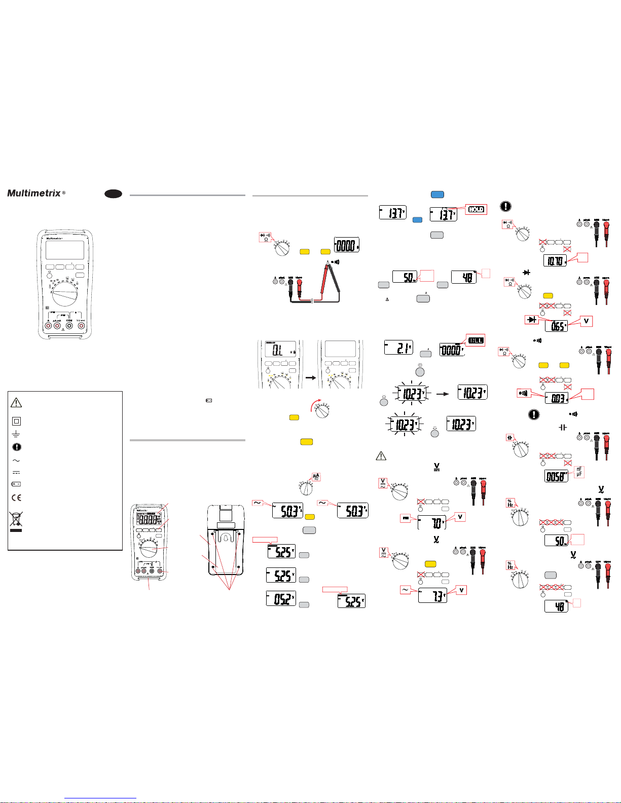
PRESENTATION
The DMM121 is a device for measuring electrical
quantities:
AC or DC voltage measurement;
DC and AC current measurement;
Frequency measurement;
Capacitance measurement;
Resistance measurement, continuity measurement
with buzzer or diode test.
LCD display
unit
Keys
Input
terminals
Switch
Impact-resistant
jacket
Battery
compartment
cover
Definition of measurement categories
Measurement category IV corresponds to
measurements taken at the source of low-voltage
installations.
Measurement category III corresponds to
measurements on building installations.
Measurement category II corresponds to
measurements taken on circuits directly connected
to low-voltage installations.
USE
IINSERTING THE BATTERIES
See § Maintenance.
TEST OF OPERATION
SELECT
CHANGING RANGES
OFF
OFF
Hz
%
HOLD OF THE DISPLAY
Hz %
Hz %
HZ AND % FUNCTIONS
For AC voltage and current measurements, they are used
to display the frequency and the duty cycle of the signal
measured, respectively.
REL D FUNCTION
The REL D key is used to subtract the value displayed
at the time the key is pressed from all subsequent
measurements values and to display the result of the
subtraction. This function is not available when “OL” is
displayed.
The automatic power down function of the device is
reactivated when the device is switched back on.
CHANGING MODES
Several modes may be available for a given function
(existence of additional modes indicated by a yellow
symbol). Press the SELECT key to change which mode
is active.
+
SELECT
OFF
OFF
Hz
Diode test
Ω
OFF
OFF
Hz
%
Continuity test
OFF
OFF
Hz
%
+
Ω
R < 90 Ω =
+
Measurement of the frequency of the signal ( )
OFF
OFF
Hz
Measurement of the duty cycle ( )
Hz
%
OFF
OFF
Hz
%
RANGESELECT HOLD
OFF
OFF
REL
Hz %
Hz
%
DMM 121
RANGESELECT HOLD
OFF
OFF
REL
Hz %
Hz
%
DMM 121
30 min
Hz
+
Hz %
Prop
Hz
%
%
Battery
compartment
cover screws
REL
Resistance measurement
BACK-LIGHTING
De-activating the automatic power down
MEASUREMENTS
The input voltage must not exceed 600V.
DC voltage measurement
Capacitance measurement
SWITCHING OFF THE MULTIMETER
Manual switching off
Set the switch to OFF.
Automatic power down
OFF
OFF
Hz
%
≈
AC voltage measurement
+
+
Resistance and capacitance measurements and
diode and continuity tests must be performed
on voltage-free circuits.
DMM121
Multimeter
SELECT
RANGE
REL
HOLD
Hz %
OFF
OFF
Hz
%
OFF
OFF
Hz
SELECT
SELECT
SELECT
+
SELECT
SELECT
+
SELECT
RANGESELECT HOLD
MULTIMETER
10A
OFF
OFF
REL
Hz %
Hz
%
DMM 121
RANGESELECT HOLD
MULTIMETER
10A
OFF
OFF
REL
Hz %
Hz
%
DMM 121
GB
WARNING, risk of DANGER! The operator
must refer to this user’s manual whenever this
danger symbol appears.
Equipment protected by double insulation.
Earth.
Instruction that must be read and understood.
AC - Alternating current.
DC - Direct current.
Battery.
The CE marking indicates conformity with
European directives.
The rubbish bin with a line through it means
that in the European Union, the product
must undergo selective disposal for the
recycling of electric and electronic material,
in compliance with Directive WEEE 2002/96/
EC. This equipment must not be treated as
household waste.
OFF
OFF
Hz
%
>2s
AUTO RANGE
AUTO RANGE
RANGE
RANGE
RANGE
HOLD
80 sec.
RANGESELECT HOLD
REL
Hz %
RANGESELECT HOLD
REL
Hz %
RANGESELECT HOLD
REL
Hz %
RANGESELECT HOLD
REL
Hz %
RANGESELECT HOLD
REL
Hz %
RANGESELECT HOLD
REL
Hz %
RANGESELECT HOLD
REL
Hz %
Hz
%
OFF
OFF
Hz
%
RANGESELECT HOLD
REL
Hz %
Page 2
For safety reasons this fuse must always be
replaced by an identical model:
F1: 10x38, type FF, 10A/600V
F2: 6.3x32, type FF, 630mA/600V
When the current measured exceeds the rating of the
fuse, the fuse may blow.
REPAIR
Return the instrument to your distributor for any work to
be done, whether under the warranty or not.
If you have to ship the instrument, it is best to use its
original packaging and to state as clearly as possible,
in a note attached to the equipment, the reasons for the
transfer.
WARRANTY
The equipment is warranted against defects of materials
or workmanship, in accordance with the general terms
of sale.
During the warranty period (1 year), the instrument must
be repaired only by the manufacturer, who reserves
the right to choose between repairing it or replacing it,
entirely or partially.
If the equipment is sent back to the manufacturer,
carriage is paid by the customer.
The warranty does not apply in the following cases:
Inappropriate use of the equipment or use with
incompatible equipment;
Modifications made to the equipment without the
explicit permission of the manufacturer’s technical
staff;
Work done on the device by a person not approved
by the manufacturer;
Adaptation to a particular application not anticipated
in the definition of the equipment or not indicated in
the user’s manual;
Damage caused by shocks, falls, or floods.
TO ORDER
DMM 121 ................................................... P06231421Z
POWER SUPPLY
Battery: 2x1.5V AA/LR6
Mean battery life: ~400 hours
Auto power off delay: After 30 minutes without action on
the keys and/or on the switch.
COMPLIANCE WITH INTERNATIONAL STANDARDS
Compliant with standards IEC 61010-1 and IEC 610102-033 for 600V CAT III installations.
Maximum input voltage: 600V between terminals.
ELECTROMAGNETIC COMPATIBILITY
Emissions and immunity in an industrial environment
per EN 61326-1.
MAINTENANCE
Except for the fuse and the batteries, the
instrument contains no parts that can be replaced by
personnel who have not been specially trained and
accredited. Any unauthorized repair or replacement of a
part by an “equivalent” may gravely impair safety.
CLEANING
Disconnect the unit completely and turn the rotary switch
to OFF.
Use a soft cloth, dampened with soapy water. Rinse with
a damp cloth and dry rapidly with a dry cloth or forced
air. Do not use alcohol, solvents, or hydrocarbons.
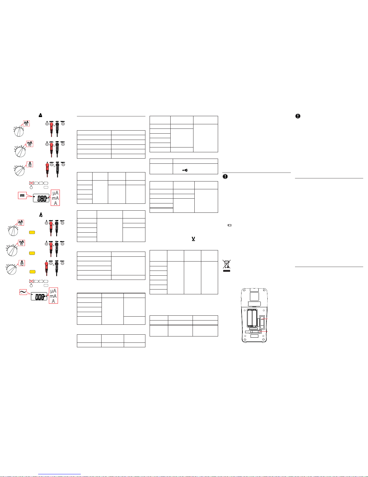
REPLACEMENT OF THE BATTERIES
The symbol indicates that the batteries are dead and
must be replaced.
To replace the batteries, proceed as follows:
Disconnect the unit completely and turn the rotary
switch to OFF;
Remove the jacket;
Unscrew and remove the 4 battery compartment
cover screws;
Remove the old batteries and insert the new ones,
with the polarities as indicated.
Spent batteries must not be treated as ordinary
household waste. Take them to the appropriate
recycling collection point.
REPLACING THE FUSE
When the measurement current exceeds the current
rating of the fuse, the protection fuse may blow.
Resistance measurement
Range
Intrinsic
uncertainty
Observation
400.0 Ω 0.5 % + 3 ct
No-load voltage:
approx. 0.4V
4.000 kΩ
0.5 % + 2 ct
40.00 kΩ
400.0 kΩ
4.000 MΩ
40.00 MΩ 1.5 % + 3 ct
Continuity measurement
Range Observations
400.0 Ω
- No-load voltage: approx. 0.4V
-
: R < 90 Ω ± 40 Ω
Capacitance measurement
Range
Intrinsic
uncertainty
Observation
50.00 nF 1.5 % + 15 ct
The response
time may be
long at high
values
500.0 nF 2 % + 5 ct
5.000 μF
5 % + 5 ct50.00 μF
100.0 μF
Measurement of frequency and duty cycle (Hz% key)
in voltage and current
Function limited to industrial frequencies.
Minimum input level: 10% of the range in voltage and
55% of the range in current.
The values of the duty cycle are indicative.
Frequency measurement (input )
The “Hz” setting eliminates the constraint of the limited
pass band in voltage measurements.
Range
Minimum
input
voltage
Intrinsic
uncertainty
Observa-
tion
5.000 Hz
2 Vpp
0.1 % +
3 ct
Given for
a square
wave
50.00 Hz
500.0 Hz
5.000 kHz
50.00 kHz
500.0 kHz
5.000 MHz
ENVIRONMENTAL CONDITIONS
Indoor use
Altitude < 2.000 m
Degree of pollution: 2
In use In storage
Temperature -10 °C ... +50 °C -20 °C ... +60 °C
Relative
humidity
≤ 80 %RH
(without
condensation)
≤ 70 %RH
(without
condensation)
CONSTRUCTIVE CHARACTERISTICS
Dimensions L x W x H: 181 x 92 x 57 mm
Weight: approx. 400 g
CHARACTERISTICS
ELECTRICAL CHARACTERISTIC
Reference conditions
Quantity of influence Reference value
Temperature 23 ± 2°C
Relative humidity 45 to 75% RH
DC measurement Without AC component
AC measurement Sine wave without DC
Frequency measurement Square wave without DC
The intrinsic uncertainties are stated in
± (x % of reading + Y points) from 10 to 100% of the range
AC voltage measurement
Range Frequency
Intrinsic
uncertainty
Input
resistance
400.0 mV
40 Hz 500 Hz
1 % + 10 ct ~ 11 MΩ
4.000 V
1 % + 5 ct ~ 10 MΩ
40.00 V
400.0 V
600 V
DC voltage measurement
Range
Intrinsic
uncertainty
Input resistance
400.0 mV
0.5 % + 3 ct
≥ 100 MΩ
4.000 V ~ 11 MΩ
40.00 V
~ 10 MΩ400.0 V
600 V*
DC current measurement
Intrinsic uncertainty: 1.5% + 3 ct
Range Protection
400.0 μA
Fuse 0.63 A /600 V
4000 μA
40.00 mA
400.0 mA
10.00 A* Fusible 10 A /600 V
* 20 A for 30 s.
AC current measurement
Intrinsic uncertainty: 1.5% + 5 ct
Range Frequency Protection
400.0 μA
40 Hz - 500 Hz
Fuse 0.63 A
/600 V
4000 μA
40.00 mA
400.0 mA
4.000
/10.00 A*
Fuse 10 A
/600 V
* 20 A for 30 s.
Diode test
Range
Intrinsic
uncertainty
No-load
voltage
4.000 V 10 % ~ 1.5 V
DC current measurement
OFF
OFF
Hz
%
OFF
OFF
Hz
AC current measurement
µA
mA
A
OFF
OFF
Hz
%
RANGESELECT HOLD
REL
Hz %
+
OFF
OFF
Hz
%
OFF
OFF
Hz
%
OFF
OFF
Hz
+
+
≈
µA
mA
A
SELECT
SELECT
SELECT
RANGESELECT HOLD
REL
Hz %
11 - 2013
694310A02 - Ed. 2
http://www.chauvin-arnoux.com
FF 630mA/1000V
FF 10A/1000V
F1
F2
 Loading...