

Page 1

52
Dealer’s stamp
Multimessage Systems Ltd,
Unit 1 / 2, Block 26
Cranborne Industrial Estate,
Cranborne Road, Potters Bar, Herts.
EN6 3JH
Tel. 01707 644480
Fax 01707 646745
www.multimessage.co.uk
ISSUE 1.1
Revised 06/09/05
1
User Guide
Multimessage Systems Limited
ADSL Router
Model
M406
Page 2

2 51
GUARANTEE
Multimessage Systems Ltd. guarantees this product for one year from the date of purchase provided that:
• The product has only been used for its intended purpose, and has not been subjected to misuse, or been wilfully or accidentally damaged.
• The product has been installed according to the maker's lnstallation Instructions.
• The product has not been tampered with or repaired by anyone other than Multimessage Systems Ltd. or its approved agents.
If a fault occurs in this product within twelve months of purchase you should return it to where you bought it, together with the sales receipt, and
it will then be replaced or repaired free of charge.
This guarantee does not affect your stat utory rights and is applicable to the United Kingdom only.
Page 3

50 3
Contents
INTRODUCTION 4
M406 Features 4
Product Illustration 5
INSTALLATION 8
NETWORK SETTINGS 9
CONFIGURING THE ADSL ROUTER 13
ROUTER STATUS 16
Wan Configuration 19
LAN Configuration 24
PPP Configuration 25
NAT Configuration 28
Virtual Server 30
ADMIN PRIVILEGE 36
Virtual Server 30
ADSL Configuration 38
RIP Configuration 39
Password Configuration 40
Miscellaneous Configuration 41
System Log 46
Page 4

4
INTRODUCTION
The Multimessage M406 is an ADSL Ethernet Router. It is optimized
to address the growing demand for high-speed Internet access. With
an IEEE 802.3-compliant Ethernet interface, it provides connectivity
options without relying on host PC drivers.
The ADSL Ethernet Router is an "always-on" high-speed broadband
connection to the internet. Using existing twisted-pair telephone lines,
ADSL technology provides data rates more than 100 times as fast as a
traditional analogue modem, without an interruption in telephone service.
The ADSL Ethernet Router is fully compliant with the full-rate ADSL
(T1.413 Issue 2 and G.dmt) and the splitter less G.lite (G.992.2)
standards. With data transfer rates of up to 8 Mbps downstream and
1 Mbps upstream.
M406 Features
ADSL Compliance
• Compliant with ADSL standards
• Full-rate ANSI T1.413 Issue 2 and ITU G.dmt G.992.1) stand ar ds
• Splitter less ITU G.lite (G.992.2) specification
• 1 Ethernet port (dual speed 100/10-Mbps)
• HTML user interface
• 2 levels of password protection
49
Page 5
48
5
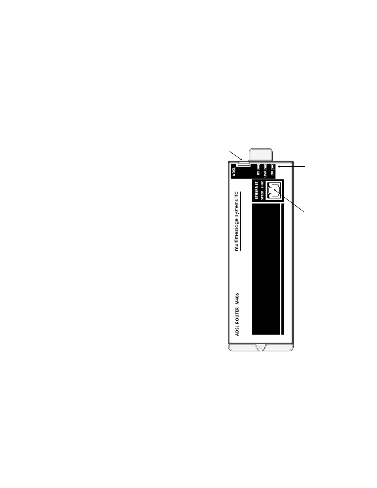
Product Illustration
1. Ethernet connector
2. ADSL status indicators
3. ADSL line connector
1
2
3
Page 6

6
ADSL Status Indicators
Indicator
Activity Colour Description
OK FLASHING Green System is alive
LINK FLASHING Green Searching for a
valid ADSL link
ON Green A valid ADSL link
is present
RX
ON or
FLASHING
Yellow Activity on ADSL
lLink
OK
The OK indicator will flash when the M406 has booted
up and is ready to use.
LINK
The Link indicator will light when a valid connection has
been established between the router and your internet
service provider (ISP). The indicator will flash until a
valid link has been established.
RX
The RX indicator will light or flash when there is activity
on the ADSL link to the ISP.
47
TECHNICAL NOTES
1. Interconnection circuits made to any port should be such that the
equipment continues to comply with the requirements of EN60950 2.3
for SELV circuits. (The voltages in a SELV circuit shall not exceed 42.4V
peak or 60V dc.) Advice should be sought from a competent engineer
before such a connection is made.
2. Refer all servicing to qualified personnel or to the Multimessage
Systems Customer Servicing Department at the address given on the
back page of this handbook.
Exchange Lines 1
Supported Protocol Full-rate ANSI T1.413 Issue 2 and ITU G.
dmt
Ethernet Ports (RJ45) 1
Supported Protocol IEE 802.3
Dimensions 200mm l x 67mm wide x 33mm deep
Weight 220g
Power Supply 24V AC 50 Hz
Power Consumption 250mA maximum
Temperature 0 to 40°C working
Relative Humidity 0 to 95% (non-condensing)
Page 7
46
Query DNS for www.conexant.com: This test checks that the host name
can be resolved to IP address though domain name servers.
Ping www.conexant.com: This test checks that the specified host can be
reached through ping request.
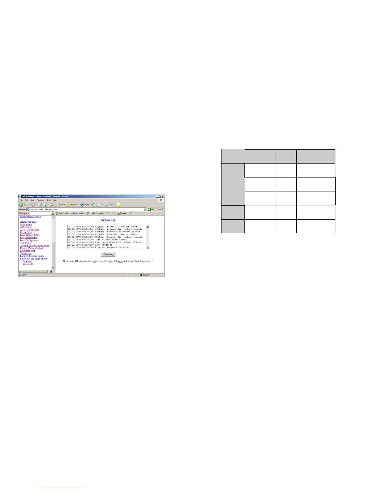
System Log
The System Log page shows the events triggered by the system.
7
Ethernet Connector Indicators
Indicator
Activity Colour Description
LINK OFF Green No link
ON Green Active link
Flashing Green Activity on link
SPEED
OFF Yellow 10Mbps
ON Yellow 100Mbps
LINK
The link indicator will light when a connection between
the Router and the switch (or a PC) has been established. If the indicator is flashing then there is activity on
the link. If a cable is plugged in and the link indicator for
that port does not light, then a wrong or defective cable
has been used.
SPEED
The speed indicator will light if the connection is connected to a 100Mbps link. The indicator will be off if the
connection is connected to a 10Mbps link, this does not
indicate a fault with the connection.
Page 8

8
INSTALLATION
The M406 should already be fitted into the M400 chassis by an installation engineer. If the M406 has not been installed please follow the installation guide supplied with the unit.
Installation of ADSL Line
• The incoming ADSL line from your service provider should be
plugged into the ADSL line connector (see product illustration
P5).
Installation of Ethernet
• Plug your Ethernet cable from the Ethernet connector on the
M406 (P5) to a spare connector on your 10/100 Ethernet Switch
(M402).
• If you don’t have an M402 then your Ethernet cable needs to be
patched via the patch panel to the required computer. Follow the
procedure below.
• Select a socket in the room required to connect the computer to.
Note down the number on the socket.
• On the patch panel, link the corresponding numbered socket on
the patch side to the Ethernet connector on the M406, using the
appropriate coloured patch lead.
• Connect the computer’s Ethernet adaptor to the allocated room
socket, then power up the computer.
• Check on the M406 that the link indicator for the port being used
shows there is a connection.
• If the indicator shows that there is a link the network connection is
ready for use.
45
LAN interface connection.
Test ADSL Synchronization: This test checks the ADSL Showtime. If
this test returns FAIL, all other tests will be skipped.
Test ATM OAM Segment Loop Back: This test sends ATM OAM F5
Segment loop back request cells to the CO. This test will pass if a
response cell is received. Since some service providers might not
Support this test, it could still work even if this test fails. If this test fails
consistently and the ADSL modem seems not to be working, make
sure the VPI and VCI are configured correctly.
Test ATM OAM End-to-End Loop Back: This test sends ATM OAM F5
End to End loop back request cells to the CO. This test will pass if a response cell is received. Since some service providers might not support this
test, it could still work even if this test fails. If this test return FAIL consistently and the ADSL modem seems not working, make sure the VPI and VCI
are configured correctly.
Test Ethernet Connect to ATM: This test checks that the ATM AAL5 mod-
ule is loaded correctly.
Test PPPoE Connection: This test checks the PPPOE connection.
Test PPP Layer Connection: This test checks the PPP authentication.
Test IP Connect to PPP: This test checks a valid IP address assigned
from the service provider.
Ping Primary DNS: This test checks that the primary DNS can be reached
through ping request.
Page 9
44
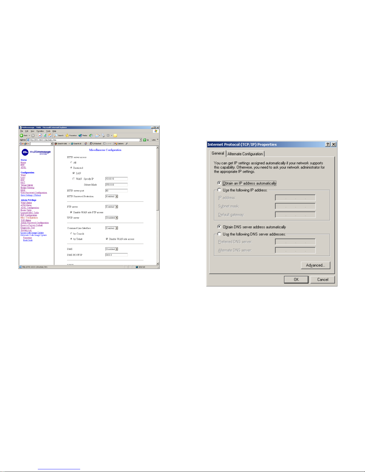
forward this packet to the DMZ host.
DMZ Host IP: The IP address of the DMZ host at LAN side.
DHCP Relay: If it is enabled, the DHCP requests from local PCs will
forward to the DHCP server runs on the WAN side. To have this function working properly, disable the NAT to run on router mode only, disable the DHCP server on the LAN port, and make sure the routing
table has the correct routing entry.
DHCP Target IP: The DHCP server runs on the WAN side.
IGMP Proxy: This is the global setting for IGMP Proxy. If it is enabled,
then the enabled IGMP Proxy on WAN PVCs will be working. Otherwise,
no WAN PVC can have IGMP Proxy working on it.
PPP reconnect on WAN access: If it is enabled, the PPP session will
be automatically established when there is a packet wants to go out the
WAN.
For the PPP connect on WAN access, the PPP will be automatically
reconnected when an URL is entered in the browser. For the Automatic
Reconnect, it will reconnect the PPP session whenever it is terminated
by ISP.
PPP Half Bridge: When the PPP Half Bridge is enabled, only one PC is
able to access the internet, and the DHCP server will duplicate the
WAN IP address from the ISP to the local client PC. Only the PC with
the WAN IP address can access the internet.
Reset to Factory Default
The Reset to Factory Default page allows users to reset the modem
to the original factory default configuration (factory reg).
Diagnostic Test
The Diagnostic Test page shows the test results for the connectivity of the
physical layer and protocol layer for both LAN and WAN sides.
Testing Ethernet LAN Connection: This test checks the Ethernet
9
NETWORK SETTINGS
TCP/IP Configuration for Windows XP
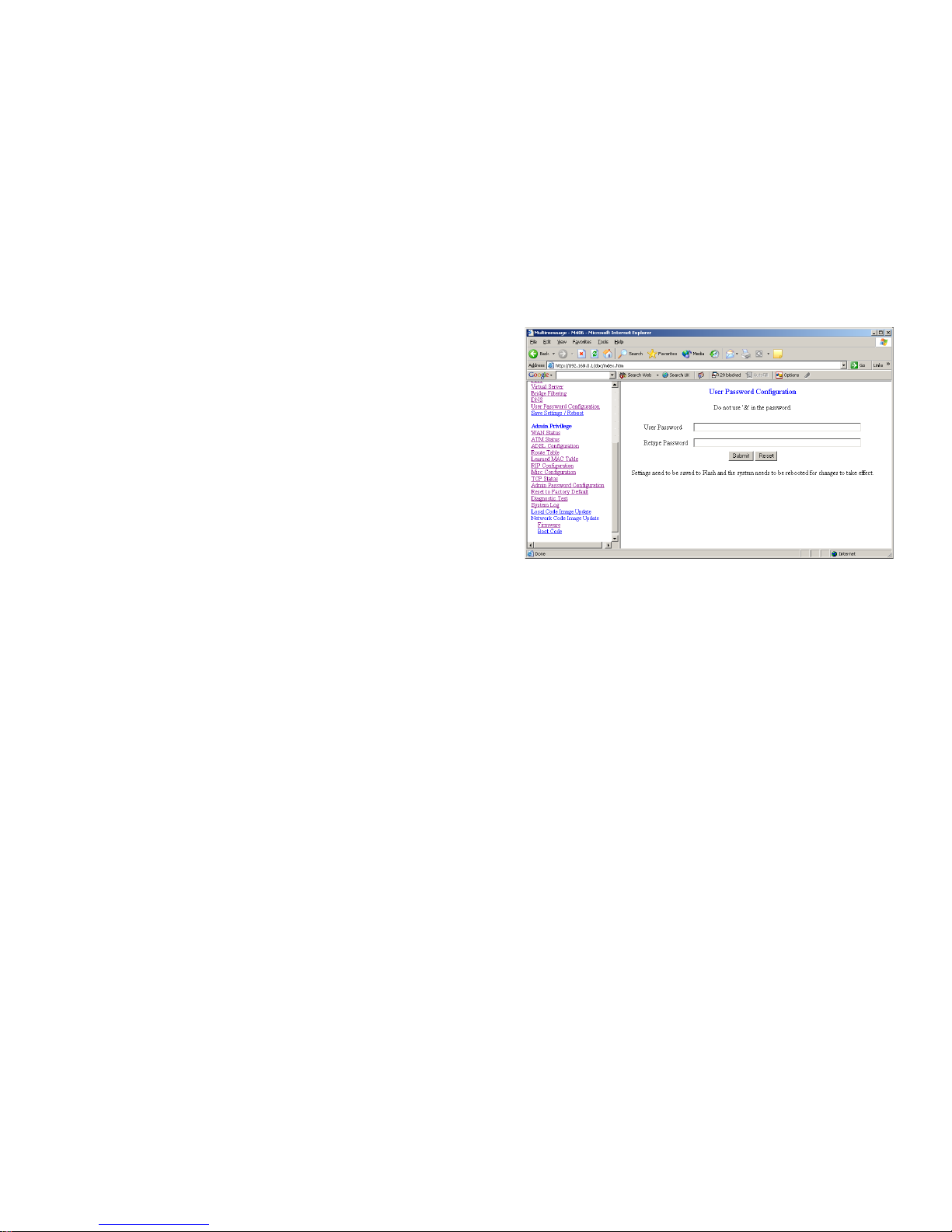
Use the following steps to configure the manager PC to be a
DHCP client. These same steps must be performed for every host PC on
your network if you use the DHCP function of the router.
• Click Start button, Settings and choose Control
Panel.
• Double click Network Connections icon.
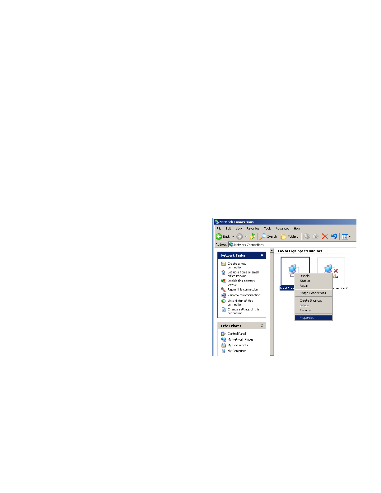
• Select "Local Area Connection" from Network Con-
nections. Right click on the icon and select Properties".
Page 10
10
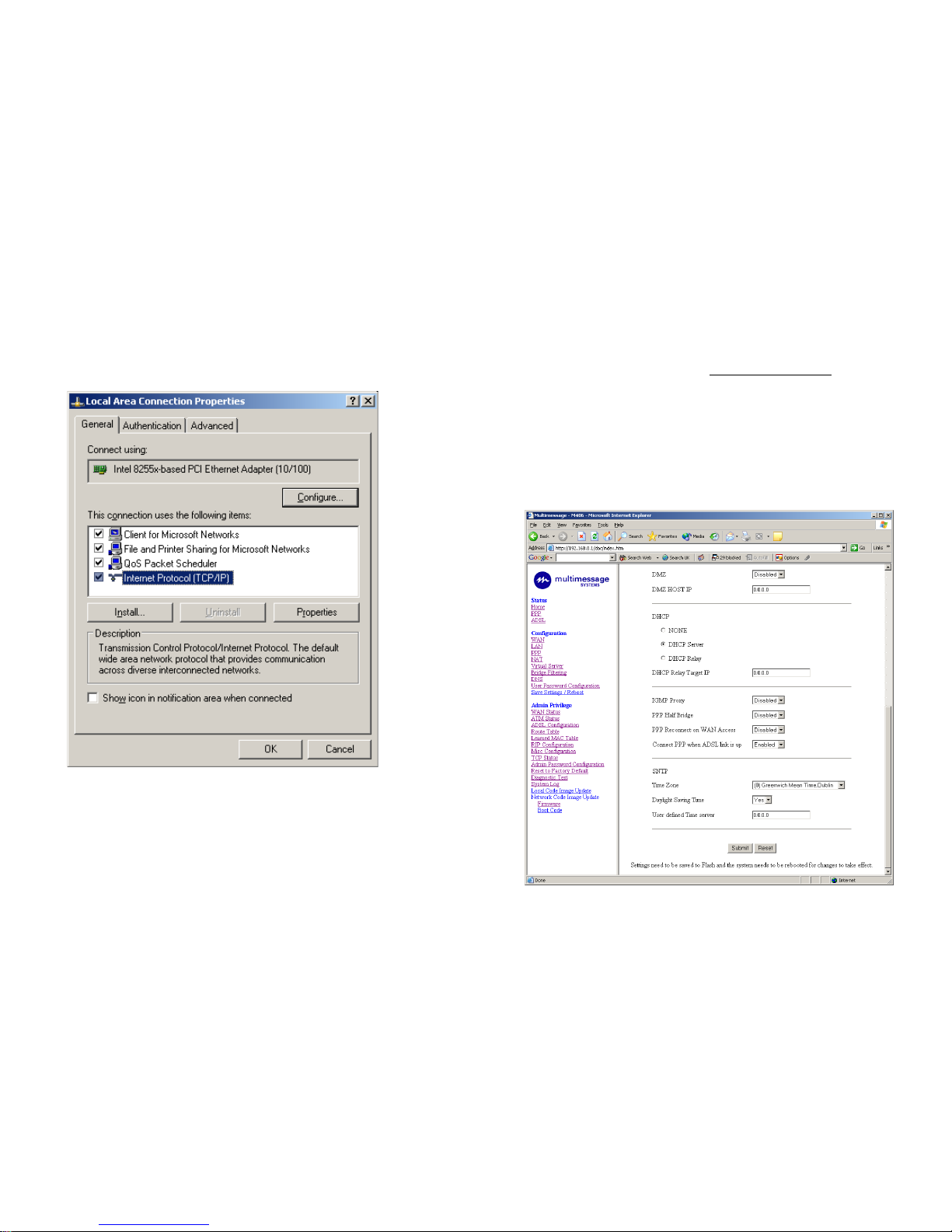
• Select the TCP/IP line that has been associated to
your network card in the General tab and click
Properties.
43
HTTP server port: This field allows the user to specify the port of the
web access. For example, when it is changed to 1001, the HTTP
server address for the LAN side is http://192.168.0.1:1001.
FTP server: This field allows the user to enable or disable the FTP co nnection.
TFTP server: This field allows the user to enable or disable the
TFTP connection.
DMZ: A DMZ (De-Militarized Zone) is added between a protected network
and an external network, in order to provide an additional layer of se curity.
When there is a suspected packet coming from WAN, the firewall will
Page 11
42
HTTP server access: This field allows the user to configure the Web
pages can be accessed from;
All: When this field is checked, it allows both WAN and LAN access to the
web pages.
Restricted LAN: This field allows the web pages access from LAN
side.
Restricted WAN Specified IP & Subnet Mask: This field allows the
web access from WAN side with a specific IP and subnet mask.
11
• Get IP address from router (DHCP)
Page 12
12
Check your TCP/IP Protocol
After configuring the TCP/IP protocol, you can use the ping command
to check if your computer has successfully connected to this router.
The following example shows the ping procedure for Windows XP.
First, execute the ping command in the Command prompt.
ping 192.168.0.1
If the following messages appear:
• Pinging 192.168.0.1 with 32 bytes of data:
• Reply from 192.168.0.1: bytes=32 times <10ms TTL=64
• Reply from 192.168.0.1: bytes=32 times <10ms TTL=64
• Reply from 192.168.0.1: bytes=32 times <10ms TTL=64
A communication link between your computer and this router has been successfully established. Otherwise, if you get the following messages;
• Pinging 192.168.0.1 with 32 bytes of data:
• Request timed out.
• Request timed out.
• Request timed out.
There must be something wrong in the configuring procedure or a cable
issue. Please check that the Ethernet LINK indicator is light. Or check the
TCP/IP configuration of your computer.
41
Miscellaneous Configuration
The Miscellaneous Configuration allows the user to set all the miscellaneous configurations.
Page 13
40
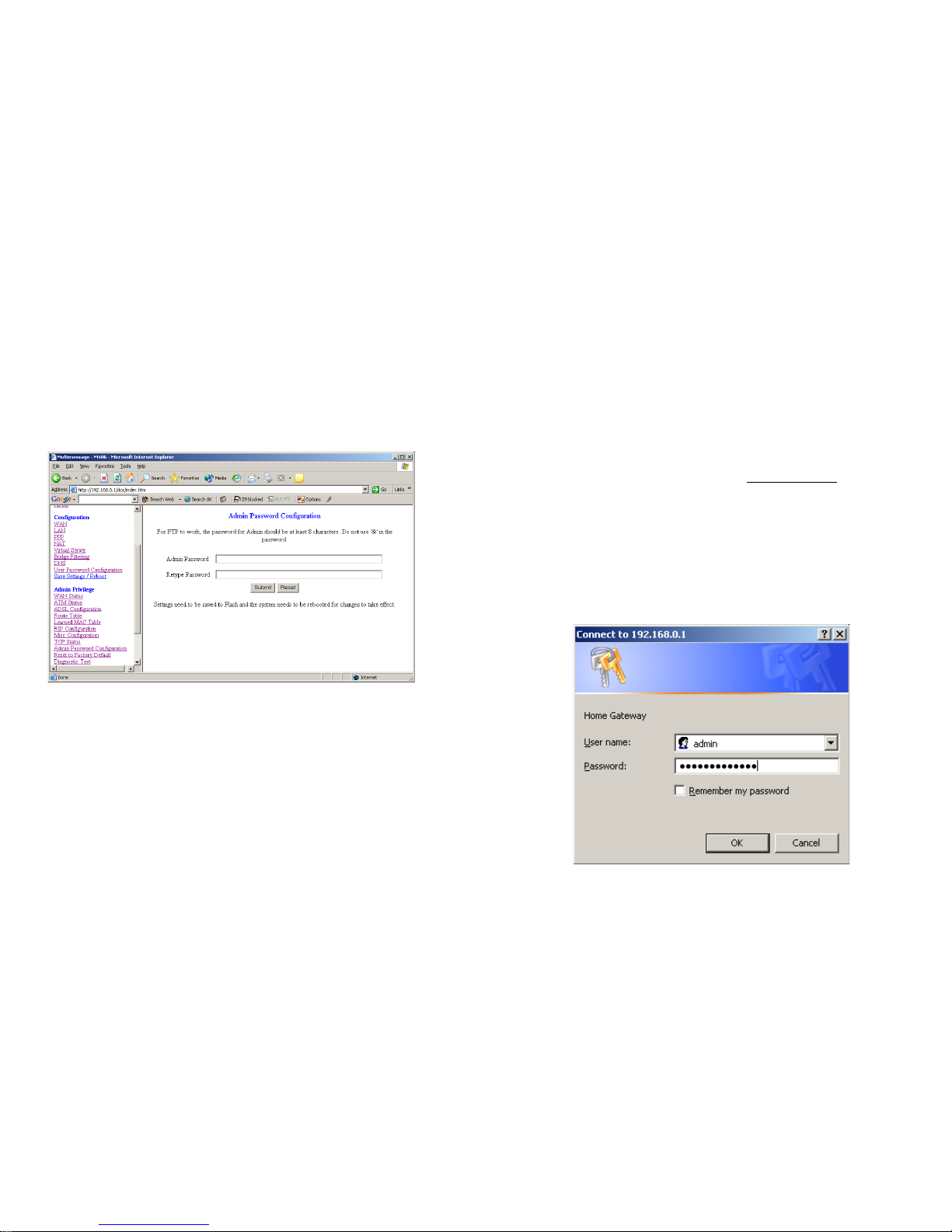
Password Configuration
The Password Configuration page allows the user to set the passwords
for the user and administrator.
Admin
The Admin Password Configuration page allows the user to set the
password for the administrator.
User
The User Password Configuration page allows the user to set the password for the user.
13
CONFIGURING THE ADSL ROUTER
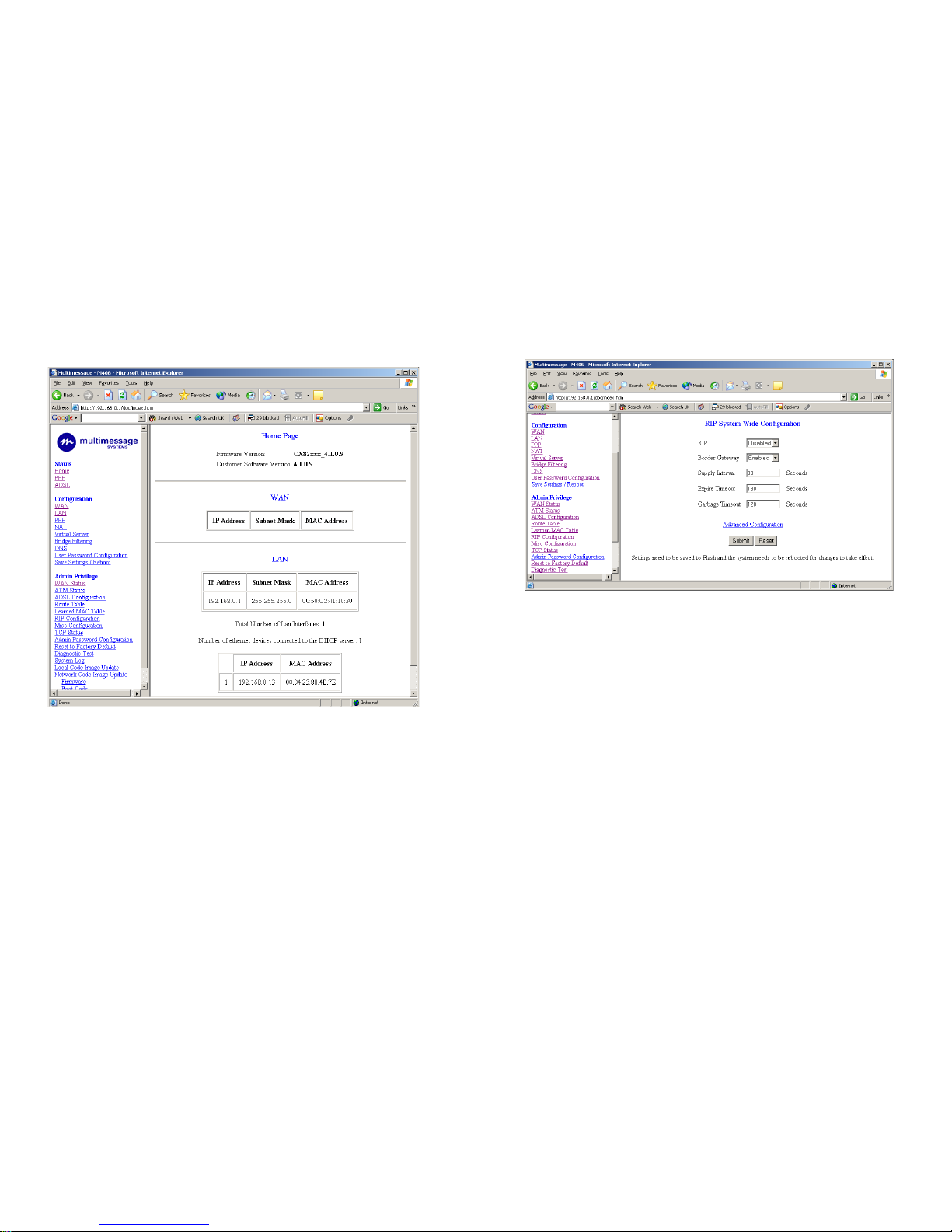
The Router offers a web-based (HTML) graphical user interface allowing
users to manage the Router using standard browser software such as Netscape Navigator or Microsoft Internet Explorer.
Accessing the Web Manager
• Launch the Web browser.
• Enter the LAN port default IP address http://192.168.0.1.
• Entry of the user name and password will be prompted. Enter the de-
fault login User Name and Password.
The default login User Name of the administrator is admin, and the
default login password is administrator.
The default login User Name for the non-administrator is user, and
the default login password is password.
Page 14
14
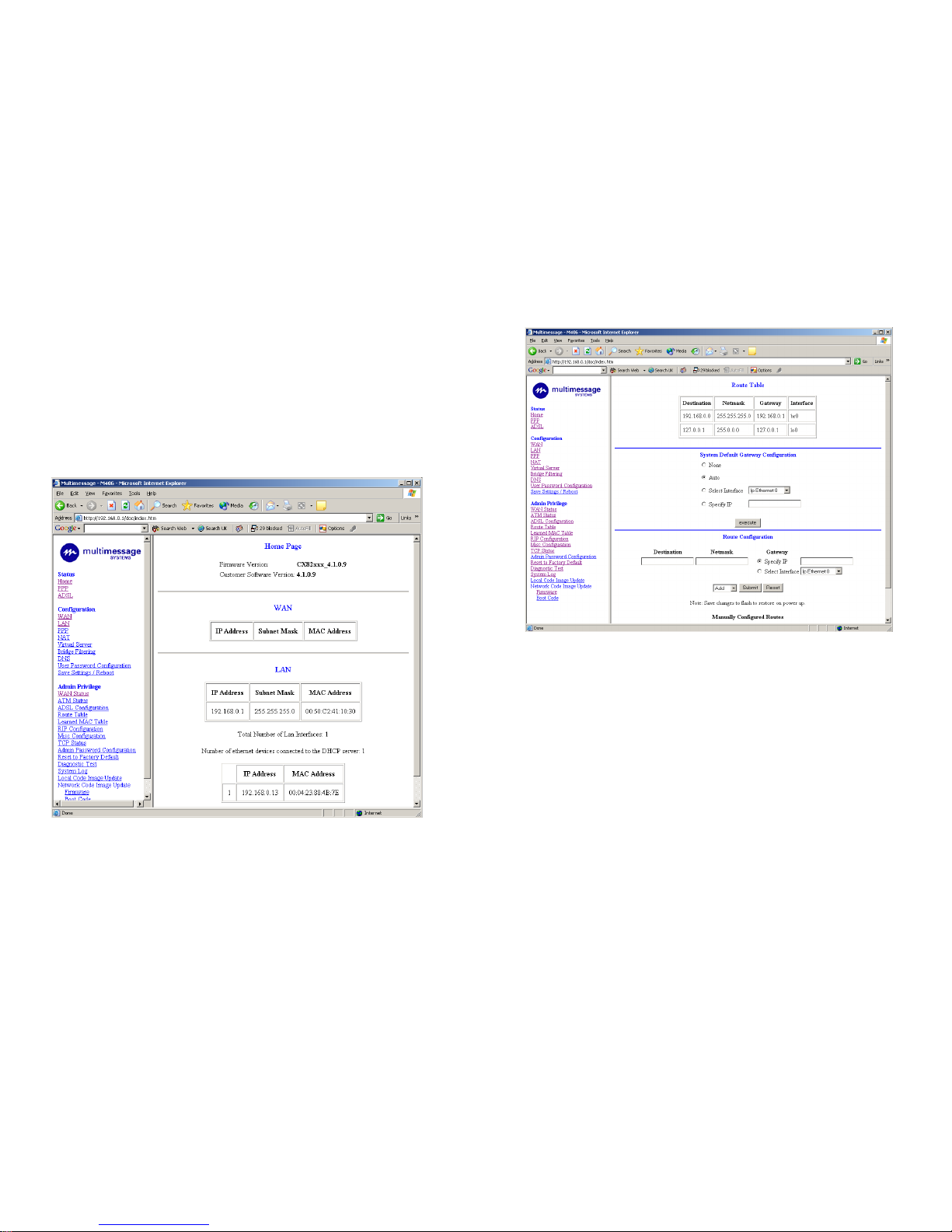
The Routers Home page is now displayed. Select the WAN Configura-
tion menu from the list on the left hand side of the page.
The adaptor is set to Pvc 0, click Submit to enter the WAN Configuration.
You need to enter your Username and Password (if applicable) for your
internet service provider. This is done in the PPP section.
39
RIP Configuration
The RIP Configuration page allows users to set the configuration for
RIP protocol.
RIP: Start or stop a RIP session. The resulting RIP session will monitor all
network interfaces that are currently available for messages from
other RIP routers.
Supply Internal: It will respond to specific requests from other
routers and transmit route updates over every known interface at the
interval specified.
Interval: The interval of the RIP information will be advertised.
Page 15
38
ADSL Configuration
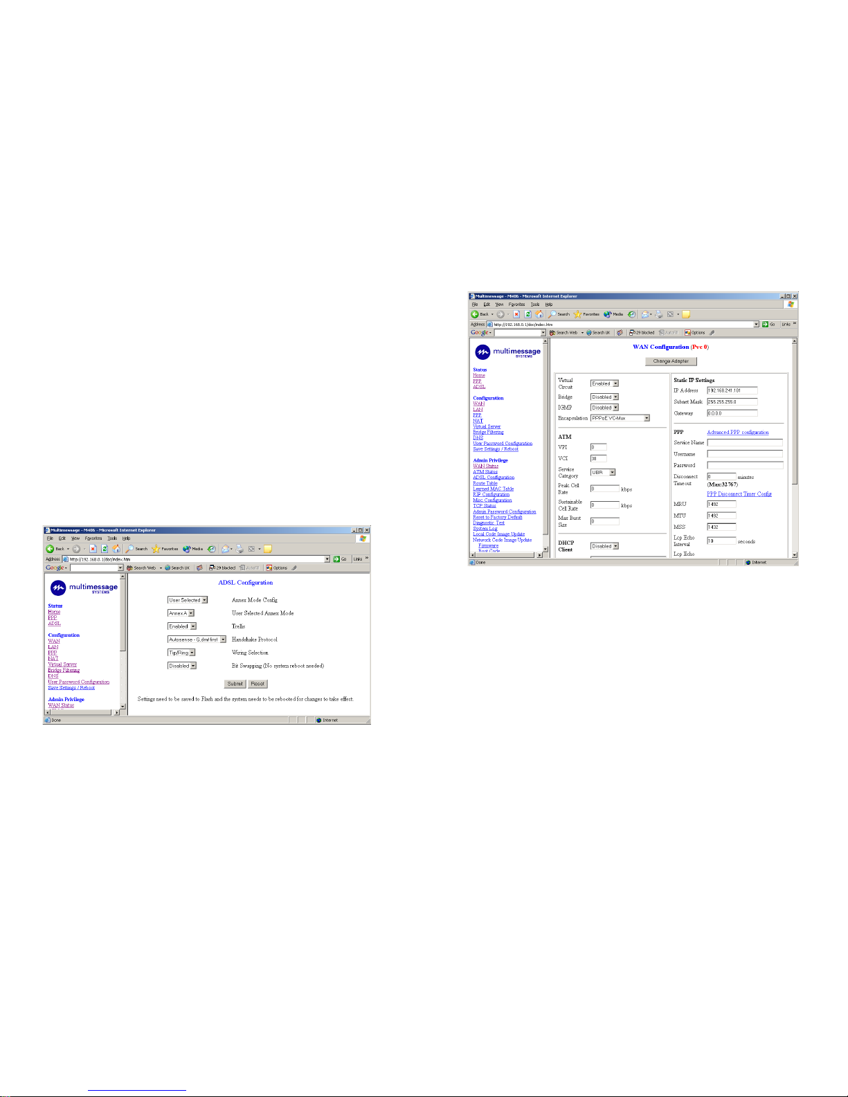
The ADSL Configuration page allows the user to set the configuration for
ADSL protocols.
Trellis: This field allows the user to enable or disable the Trellis Code. By
default, it is always enabled.
Handshake Protocol: This field allows the user to select the ADSL handshake protocol.
Wiring Selection: This field allows the user to enter the wiring selection
for the RJ-1 1.
Bit Swapping: This field allows the user to enable or disable the upstream bit swapping.
15
The default settings for the router have been set to be used with BT
ADSL, some other internet service providers may have slightly different
settings so you may need to confirm them with your internet service provider.
Settings to check with your ISP
VPI = 0
VCI = 38
Encapsulation = PPPoE VC-Mux
Click Submit at the bottom of this page.
The Router should now be ready to use.
Page 16
16
ROUTER STATUS
The links under the Status column are associated to the pages that represent the status of system and interfaces.
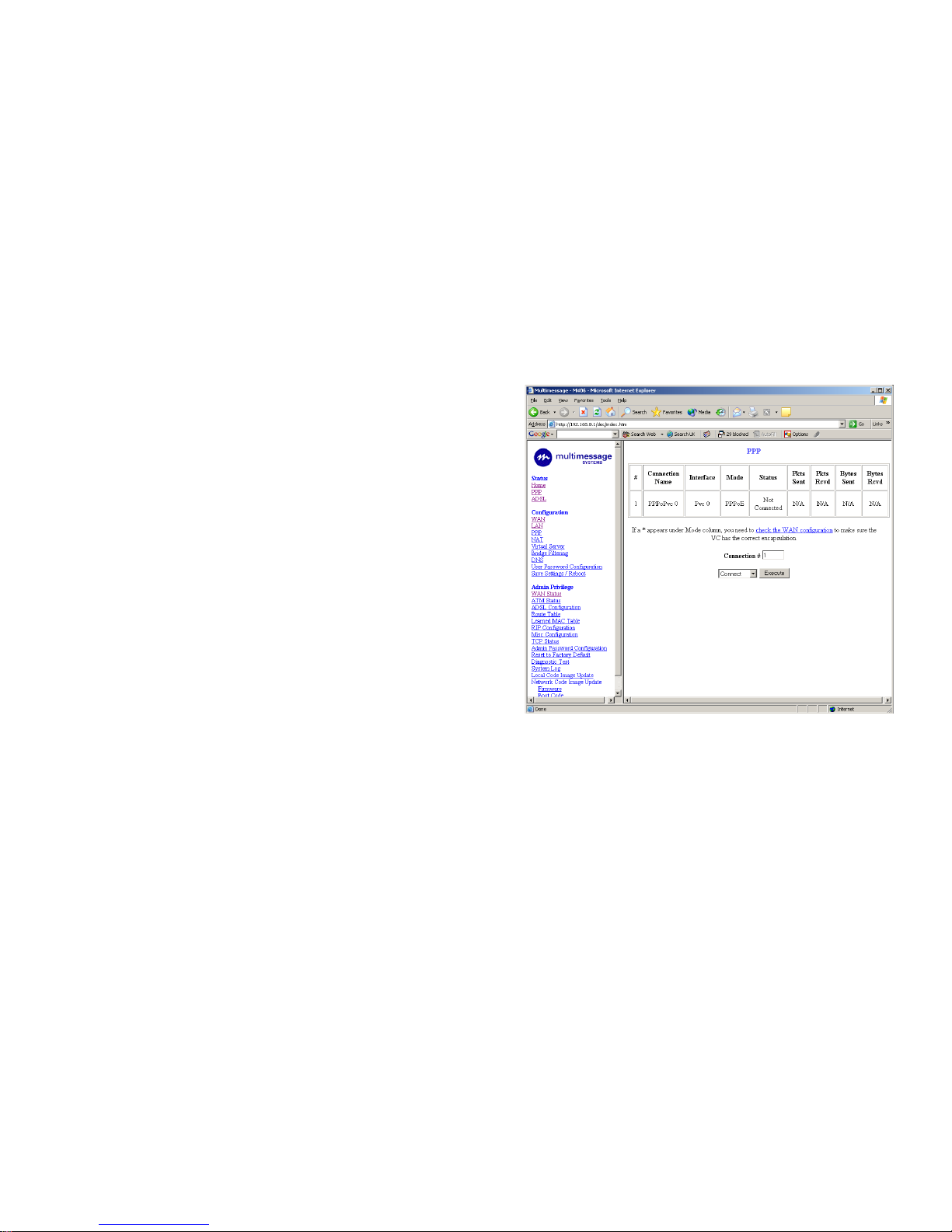
Home Page
The Home Page shows the WAN and LAN interface status and firmware
versions.
37
Destination: This field allows the user to enter the remote network or host
IP address for the static routing.
Netmask: This field allows the user to enter the Subnet Mask for the
static routing.
Gateway: This field allows the user to enter the IP address of the gateway
device that allows the router to contact the remote network or the host.
Learned MAC Table
The Learned MAC Table page shows the current learned Bridge MAC ta-
ble.
Aging Timeout: This field allows the user to enter the update period for the
MAC table.
Page 17
36
ADMIN PRIVILEGE
The links under Admin Privilege are only to be accessed and configured
when you are logged in with administrator’s login name and password.
WAN Status
The WAN Status page shows the information and status of WAN PVCs.
The DHCP Release and Renew allows the user to release and renew th e
WAN IP address in the WAN DHCP Client Enabled (dynamic) mode.
ATM Stat u s
The ATM Status page shows all the statistics information of ATM cells.
TCP Status
The TCP Status page shows the statistics for all TCP connections.
Route Table
The Route Table page displays the routing table and allows users to
manually enter the routing entry. The interface brO means the Ethernet interface and lo0 means the loop back interface.-
17
PPP Page
The PPP status page shows the status of PPP for each PPP interface.
PPP: These fields display the Connection Name (user defined),
Interface (PVC), Mode (PPPoE or PPPoA), Status (connected or not
connected), Packets Sent, Packets Received, Bytes Sent and Byte Received.
Connect and Disconnect: This field allows the user to manually connect/disconnect the PPP connection for each PPP interface.
Page 18
18
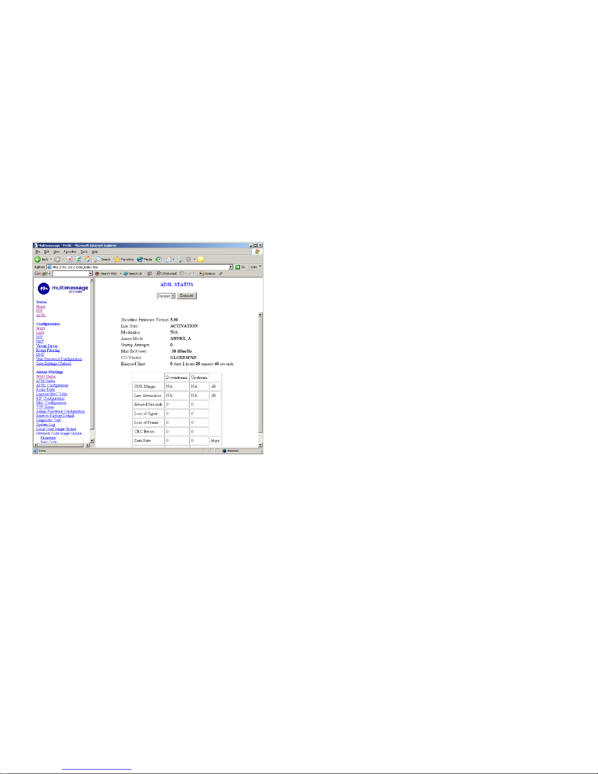
ADSL Status Page
The ADSL Status page shows the ADSL physical layer status.
35
Save Settings
The Save Settings page allows users to save the new configuration to the
flash and reboot the system.
When you change all settings, you must click save settings and click sub-
mit. The router will save the settings and software will reset the router after about 20 seconds.
Page 19
34
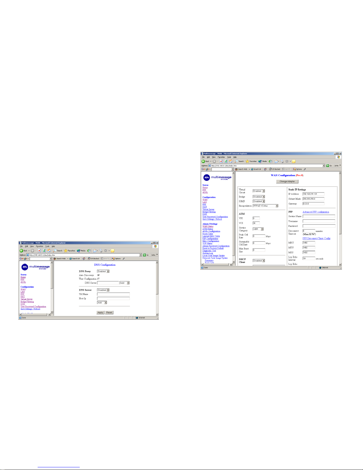
There are four DNS proxy modes available.
• Disable DNS Proxy: The LAN port does not process the DNS query
message. For the DHCP requests from local PCs, the DHCP server
will set the user-configured preferred DNS server or alternate DNS
server whichever is available as the DNS server. All DNS query
messages will then be directly sent to the DNS servers.
• Use Auto Discovered DNS Servers Only: The DNS proxy will
store the DNS server IP addresses obtained from the DHCP client
or PPP into the table. All DNS query messages will be sent to one of
the dynamically obtained DNS servers.
• Use User Configured DNS Servers Only: The DNS proxy will use
the user-configured preferred DNS server and alternate DNS
server. All DNS query message will be sent to one of the DNS servers.
• Auto Discovery + User Configured: The DNS proxy's table has all
the IP addresses of dynamically obtained and user configured DNS
servers.
19
WAN Configuration
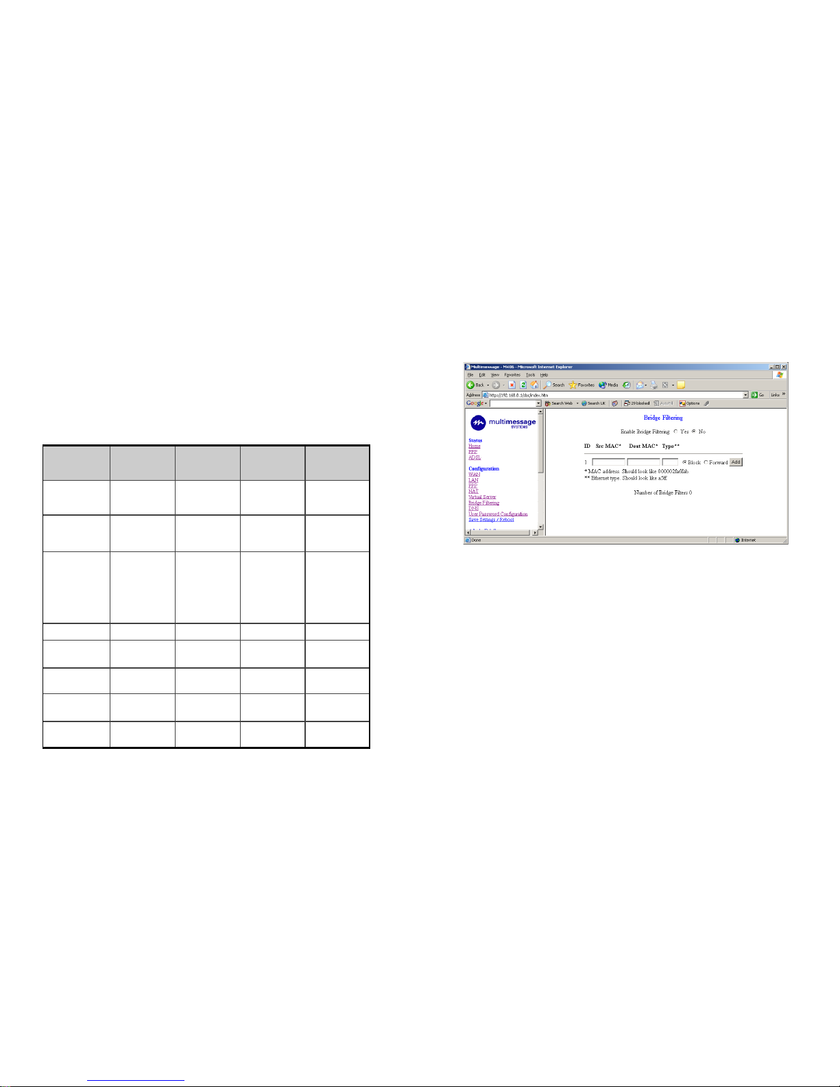
The WAN Configuration page allows the user to set the configuration
for the WAN/ADSL ports.
PVC Settings
Under PVC Setting, it provides the configurations for IP address,
Subnet Mask, Gateway and VPI/VCI. Current firmware supports
eight PVCs. To switch between the PVCs, please choose the options of virtual circuit and click on the Submit button to switch over.
MAC Spoofing
The MAC Spoofing is developed to solve the scenario when the
ISP only recognizes one MAC address. Copy the ISP-recognized
Page 20
20
MAC address here.
ATM
Service Category: UBR and CBR are supported from the ATM.
Bandwidth: Bandwidth setting takes effect only when the CBR is se-
lected. The maximum available bandwidth is from the upstream data
rate of ADSL status page.
Encapsulation, Bridge, PPP, and DHCP Client
Use Table 4-1 to configure a valid setting for each PVC.
Table 4-1
WAN Configuration
Bridge Mode Router
(PPPoA/PPPoE)
Mode
Router Mode
(Dynamic IP)
Router Mode
(Static IP)
IP address N/A Automatically
assigned by
Automatically
assigned by
Provided by
ISP
Subnet
Mask
N/A Automatically
assigned by
Automatically
assigned by
Provided by
ISP
Encapsulation 1483 Bridged
IP LLC,1483
Bridged IP VCMux
PPPoA
LLC/VC-Mux,
PPPPoE
LLCNC-Mux
1483 Bridged/
Routed IP
LLC,1483
Bridged/Routed
IP VC-Mux,
Classical IP
1483 Bridged/
Route d IP
LLC,1483
Bridged/Route d
IP VC-Mux,
Classical IP
Bridge
Enabled Disabled Disabled Disabled
PPP N/A Provided by
ISP
N/A N/A
PPP User Name N/A Provided by N/A N/A
PPP Password N/A Provided by
ISP
N/A N/A
DHCP Client
enable
Unchecked Unchecked Checked Unchecked
33
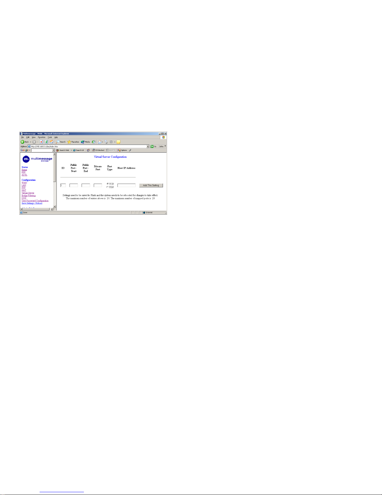
MAC address will then be filtered out. If Forward is selected, then
the packets will be forwarded to the destination PC.
• Type: Enter the hexadecimal number for the ethernet type field in
ethernet_II packets. For example, 0800 is for IP protocol.
DNS Configuration
Domain Name Service (DNS) is a service used on the Internet for resolving
fully qualified domain names (FQDN) to their Internal Protocol (IP) address.
You can type the preferred DNS server IP address, Alternative DNS server
IP address that provided by ISP or automatically assigned by ISP. Click
submit and save settings to save your setting.
The DNS Configuration page allows the user to set the configuration of
DNS proxy.
The router supports the DNS proxy function. For the DHCP requests from
local PCs, the DHCP server will set the LAN port IP as the default D NS
server. Thus, all DNS query messages will come into LAN port
first. The DNS proxy on the ADSL modem recorded the available DNS
servers, and forward DNS query messages to one of DNS server.
Page 21
32
Public Port: This field allows the user to enter the port number of the
public network.
Private Port: This field allows the user to enter the port number of the
private network. In most cases, the private port number is the same
as the public port number.
Host IP Address: This field allows the user to enter the private network IP
address for the particular server.
Bridge Filtering
The Bridge Filtering configuration page allows users to set the
configuration of IP filtering.
• Source MAC: When the bridge filtering is enabled, enter the
Source MAC address, select Block and click Add. Then all incom-
ing WAN and LAN ethernet packets matched with this source MAC
address will be filtered out. If Forward is selected, then the packets
will be forwarded to the destination PC.
• Destination MAC: When the bridge filtering is enabled, enter the
Destination MAC address, select Block and click Add. All incom-
ing WAN and LAN ethernet packets matched with this destination
21
PPP
The router supports multiple PPP sessions per PVC. The PPP configuration in the WAN configuration page is for the first PPP session for e ach
PVC. The predefined PPP Account Name (Account ID) is "Simple
PPP Account 0" for PVCO and predefined PPP Connection Name is
"Simple PPP Session 0" for PVCO. For the other PVC X, the predefined account name and connection name will be Simple PPP Account X and Simple PPP Session X. X is the PVC number from 1 to 7.
It can support up to a total of 16 PPP sessions, and each PVC can
support up to 8 PPP sessions. The multiple PPP sessions may be
configured with any combination over 8 PVCs.
For the multiple PPP sessions, please go to PPP Configuration page.
Service Name: The service name of PPP is required by some ISPs.
If the ISP does not provide the service name, please leave it blank.
Disconnect Timeout: The Disconnect Timeout allows the users to set the
specific period of time to disconnect from the ISP. The default is 0,
which means never disconnect from the ISP.
MRU: Maximum Receive Unit indicates the peer of PPP connection the
maximum size of the PPP information field this device can be received.
The default value is 1492 and is used in the beginning of the PPP
negotiation. In the normal negotiation, the peer will accept this MRU
and will not send a packet with an information field larger than this
value.
MTU: Maximum Transmission Unit indicates the network stack of
any packet that is larger than this value will be fragmented before
the transmission. During the PPP negotiation, the peer of the PPP
connection will indicate its MRU and will be accepted. The actual MTU of
Page 22

22
the PPP connection will be set to the smaller one of MTU and the
Peer's MRU. The default value is 1492.
MSS: Maximum Segment Size is the largest size of data that TCP will send
in a single IP packet. When a connection is established between a LAN client and a host in the WAN side, the LAN client and the WAN host will
indicate their MSS during the TCP connection handshake. The default
value is 1432.
Automatic Reconnect: When it is checked, it will maintain the PPP connection all the time. If the ISP shuts down the PPP connection, it will automatically reconnect PPP session.
Authentication: When AUTO option is chosen, the PAP mode will run first
then CHAP.
Host Name: Required by some ISPs. If the ISP does not provide the host
name, please leave it blank.
IGMP
IGMP relay/proxy specification and environment:
• Support IGMP proxy/relay function for ADSL modem, based on the
following requirement and case.
• On CO side, there must be at least one IGMP querier (router) present. IGMP querier will send IGMP query packet. The ADSL modem
is responsible to relay these IGMP query to Ethernet.
• End-user multicast application device sends IGMP report while re-
ceiving IGMP query or being activated by user, the ADSL modem
should be responsible to proxy (that is, change source IP to ADSL
modem's WAN IP) the IGMP report to ADSL WAN side, include all
PVCs. The same case is for IGMP leave packet.
31
tec t your Intranet, so all hosts behind this product are invisible to the outside world. If you wish, you can make some of them accessible by enabling the virtual server.
The Virtual Server allows you to set up public services, such as a web
server, FTP, E-mail etc. that can be accessed by external users of the
internet. Each service is provided by a dedicated network computer
configured with a fixed IP address.
Set up private network computers to act as servers and configure each
server with a fixed IP address.
Enter the desired service port numbers in the public port and private port field and specify port type as TCP or UDP.
Well-known ports are
Click Add this setting button after you set and click save
settings to save all configuration.
Port Number Service Port Number Service
7 Echo 79 Finger
20,21 FTP 80 HTTP
23 Telnet 110 POP3
25 SMTP 161 SNMP
53 DNS 162 SNMP Traps
Page 23

30
Session Name: This field allows the user to enter his/her own session
name to distinguish different NAT sessions for different interfaces
among different PPP sessions and different PVCs.
Interface: This field allows the user to choose specific WAN interface (PVC or PPP Session) for NAT Session.
NAT Session Name Status will be displayed at the bottom of this page
to show all the Session Names with its WAN Interface.
Click the link Go back to NAT Configuration to the NAT configuration
page. Select the NAPT option. Select the Session Name and assign the
PC IP address, and choose the Add action. Click the Submit button and go
to the Save Settings to save this configuration.
NAPT allows many entries (User IPs) per session.
Session Name Status will be displayed in the middle of this page to
show the corresponding Session Name with its IP address.
Available Sessions Status will be displayed at the end of this page to
show all the Session Names with its WAN Interface.
Virtual Server
The Virtual Server Configuration page allows users to set the configuration of Virtual Server. The router includes the Free BSD version
firewall. All UDP/TCP ports are protected from intrusion. If any specific
local PCs need to be mapped to the UDPITCP port on WAN side,
please input the mappings here.
This product's NAT firewall filters out unrecognized packets to pro-
23
• It is not necessary to relay multicast routing between two ADSL
PVCs or two interfaces in LAN side.
• Special purpose multicast packet (such as RIP 2 packet) should run
without interference.
• Table 6-1. Packet Process
Note: Before the IGMP mode is enabled; please go to the Miscellaneous Configuration page to enable the IGMP proxy. Otherwise, the
IGMP selection will not be valid.
Rx Entity Packet Class TTL Action
ADSL IGMP query 1 Relay to Ethernet
IGMP report 1 Ignore
IGMP leave 1 Ignore
General Multicast IP - Relay to Ethernet.
Ethernet IGMP query 1 Ignore
IGMP report 1 Relay to all ADSL
PVC
IGMP leave 1 Relay to all ADSL
PVC
General Multicast IP - Ignore
Page 24
24
LAN Configuration
The LAN configuration page allows the user to set the configuration for the
LAN port.
LAN IP Address & Subnet Mask: The default is 192.168.0.1 and
255.255.255.0. The user can ch ang e it to an othe r private IP address,
such as 10.0.0.2, and 255.0.0.0.
DHCP Server
System Allocated: The DHCP address pool is based on LAN port IP ad-
dress plus 12 IP addresses. For example, the LAN IP address is
192.168.0.1 ; the DHCP address pool is at the range of 192.168.0.2 to
192.168.0.14 .
User Defined: The DHCP address pool is at the range of User Defined Start
Address and User Defined End Address. The maximum pool size can be
253 IP addresses: 255 total IP addresses - 1 broadcast address - 1 LAN
port IP address.
Lease Time: The lease time is the amount of time a network user will be allowed to connect with the DHCP server. If all fields are 0, the allocated IP addresses will be effective forever.
User Mode: Under the Single User mode, the DHCP server will only allocates one IP address to the local PC. Under the Multiple User mode, the
DHCP server allocates the IP addresses specified by the DHCP address
pool.
To use the Default IP Address:
The router comes with a preset default IP address setting of 192.168.0.1 for
the LAN port. There are two ways to use this default IP address. You can
29
NAT allows only one entry (User IP) per session.
Session Name Status will be displayed at the middle of this page to
show the corresponding Session Name with its IP address.
Available Sessions Status will be displayed at the end of this page to
show all the Session Names with its WAN Interface.
NAPT ( Static )
The NAPT option maps the single WAN IP addresses to many local
PC’s IP addresses. (1xN). It is a multiple-mapping mechanism. For
each WAN interface, more than one local PC can be associated with
one WAN interface. Click the link Session Name Configuration to add
the session name for WAN interface.
Page 25
28
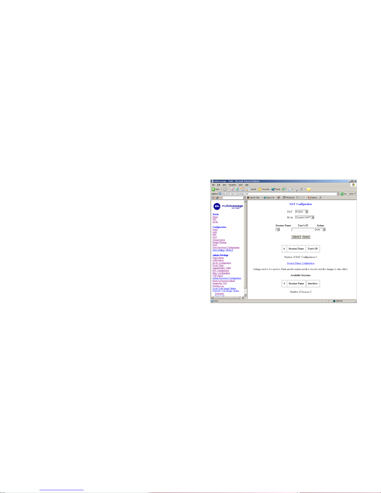
NAT Configuration
The NAT Configuration page allows the user to set the configuration for
the Network Address Translation. The default setting is Dynamic NAPT. I t
provides dynamic Network Address Translation capability between
LAN and multiple WAN connections, and the LAN traffic is routed to
the appropriate WAN connections based on the destination IP addresses and Route Table. This eliminates the need for the static NAT
session configuration between multiple LAN clients and multiple
WAN connections.
When the Dynamic NAPT is chosen, there is no need to configure the
NAT Session and NAT Session Name Configuration.
NAT (Static): The NAT option only maps single WAN IP address
to the local PC IP address. It is peer-to-peer mapping. (1x1) For
each WAN interface, only one local PC IP address can be associated with each WAN interface. Click the link Session Name Configuration to add the session name for WAN interface.
Session Name: This field allows the user to enter his/her own session Name to distinguish different NAT session for different interfaces among different PPP sessions and different PVCs.
Interface: This field allows the user to choose specific WAN Interface (PVC
or PPP Session) for NAT Session.
NAT Session Name Status will be displayed at the bottom of this
page to show all the Session Names with its WAN Interface.
Click the link Go back to NAT Configuration to the NAT configuration
page. Select the NAT option. Input the session name and the PC IP
address, and choose the Add action. Click the Submit button and go to
the Save Settings to save this configuration.
25
manually assign an IP address and subnet mask for each PC on t he L A N,
or you can instruct the router to automatically assign them using
DHCP. The DHCP function is active by default.
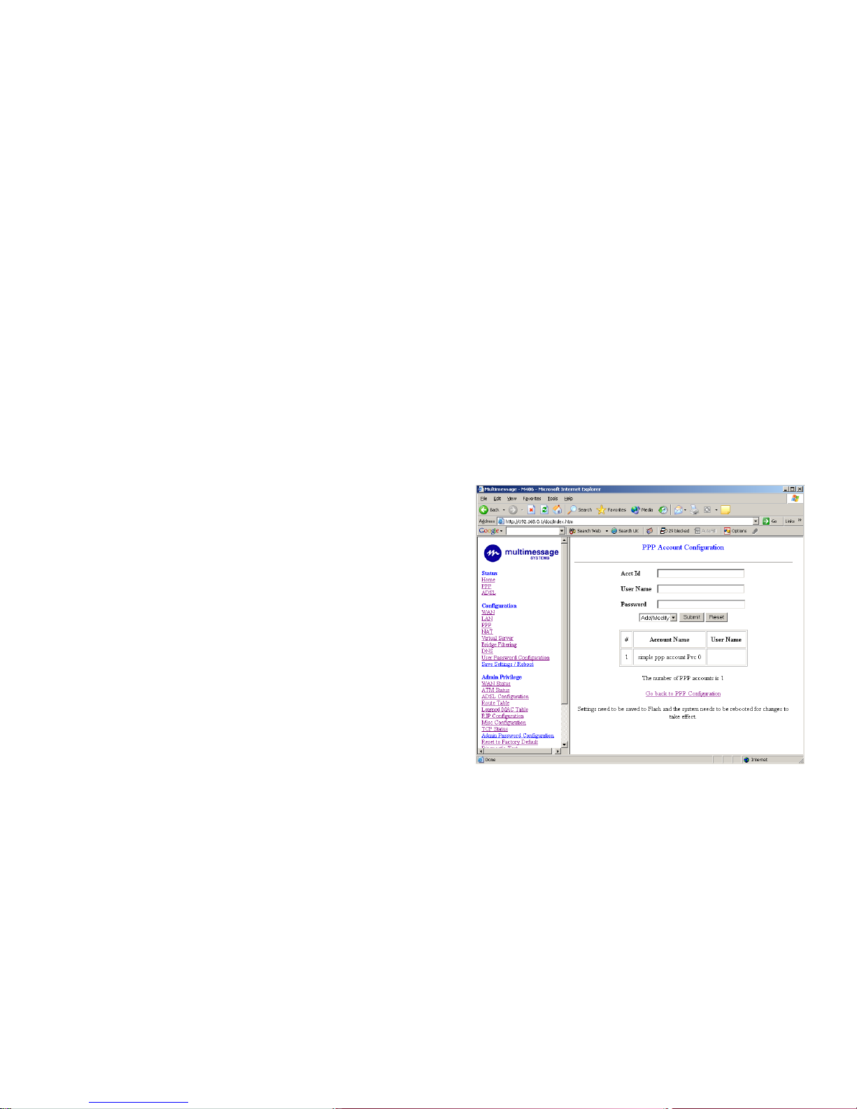
PPP Configuration
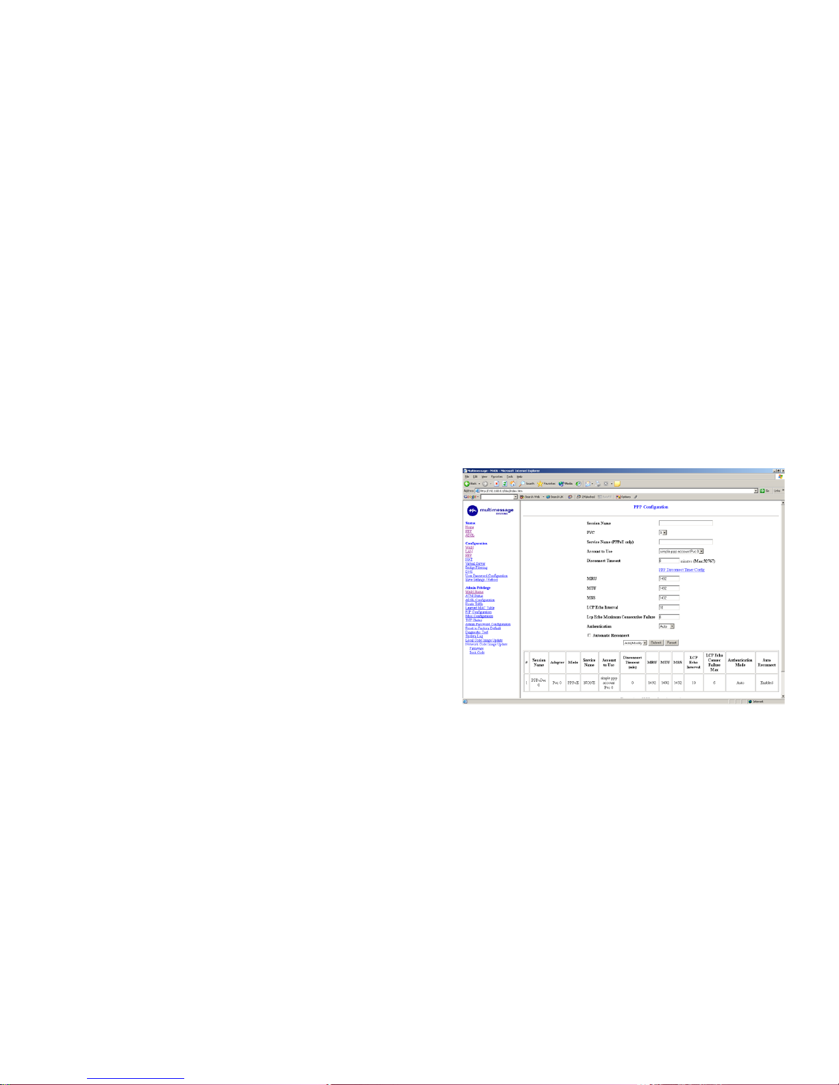
The PPP Configuration page allows the user to configure multiple PPP
sessions for each PVC. It can support up to a total of 16 PPP sessions, and
each PVC can support up to 8 PPP sessions. The multiple PPP sessions
may be configured with any combination over 8 PVCs. To configure the
PPP, must go to the PPP Account Configuration page first to configure Account ID, Users Name and Password.
Page 26
26
Account ID: This field allows the user to enter his/her own account ID to
distinguish different accounts.
User Name: Enter the PPP user name (usually provided by the ISP).
Password: Enter the PPP password (usually provided by the ISP).
PPP Account Configuration Status will be displayed at the bottom of
this page to show all the accounts with its Account Name and User
Name. (It does not show the password.)
Session Name: This field allows the user to enter his/her own session
name to distinguish different sessions for different PPP accounts and
different PVCs.
PVC: This field allows the user to choose the specific PVC for the
PPP session.
Service Name: The service name of PPP is required by some ISPs. If
the ISP does not provide the service name, please leave it blank.
Disconnect Timeout: The Disconnect Timeout allows the user to set
the specific period of time to disconnect from the ISP. The default is 0,
which means never disconnect from the ISP.
MRU: Maximum Receive Unit indicates for the PPP connection the maximum size of the PPP information field this device can be received. The
default value is 1492 and is used in the beginning of the PPP negotiation. In the normal negotiation, the peer will accept this MRU and will
not send a packet with an information field larger than this value.
MTU: Maximum Transmission Unit indicates that the network stack of
any packet that is larger than this value will be fragmented before the
transmission. During the PPP negotiation, the peer of the PPP connection will indicate its MRU and will be accepted. The actual MTU of
the PPP connection will be set to the smaller one of MTU and the
Peer's MRU. The default value is 1492.
MSS: Maximum Segment Size is the largest size of data that TCP will
send in a single IP packet. When a connection is established between a
LAN client and a host in the WAN side, the LAN client and the WAN host
will indicate their MSS during the TCP connection handshake. The defa ult
27
value is 1432.
Automatic Reconnect: When it is checked, it will maintain the PPP
connection all the time. If the ISP shuts down the PPP connection, it will
automatically reconnect the PPP session.
Authentication: When AUTO option is chosen, the PAP mode will run
first then CHAP.
PPP Configuration Status will be displayed at the bottom of this page
to show all the session names with its adapter (PVC number), mode
(PPPoA or PPPoE), service name, Account to Use (PPP Account ID),
Disconnect Timeout configuration, MRU, MTU, MSS, Authentication
Mode (Auto, CHAP or PAP), and Auto Reconnect configuration.
 Loading...