


Thank you very much for selecting our clamp earth tester.
This model is complex instrument and employs a very reliable
mechanical/electronic design. Before you use your new
instrument, read this instruction manual completely and
familiarize yourself thoroughly with all functions. With proper
use and care, your tester will give you years of satisfactory
service.
Multi Measuring Instruments Co., Ltd.
Akihabara murai-Bldg. 7F,
1-26 Kanda Sakuma-cho,
Chiyoda-ku, Tokyo, 101-0025 Japan
Tel: 81-3-3251-7016
Fax: 81-3-3253-4278
Clamp Earth Tester
MET-1
Instruction Manual

CONTENTS
1. General………………………………………………………………………….....1
2. Safety summary………………………………………………………………... 2-3
3. Measuring principle of clamp earth tester………………………………………4-5
4. Specification……………………………………………………………………..6-7
5. Panel description…………………………………………………….…………..8-9
6. Preparation before use…………………………………………………………...10
6-1. Battery charging……………………………………………………………..10
6-2. Rechargeable battery……………………………………………………….10
Precaution on charging battery…………………………………………….....10-11
7. Operation…………………………………………………………………………12
7-1. AC current measurements………………………………………………….12
7-2. Earth resistance measurements………………………………………..13-14
7-3. Measurement by TERMINALS Out mode...........................……………….15
8. Measuring example……………………………………………………………....16
8-1. Electric installation…………………………………………………..........16-17
8-2. Earth resistance measurements for the outdoor appliance………………..18
8-3. Earth resistance measurements for multiple earth system………………...18
8-4. Earth resistance measurements for the earthing electrode………………..19
8-5. Earth resistance measurements for telecommunication system………….20
8-6. Measurements for the earting connection of the outlet…………………….20
8-7. Measurement for the active line........................................................................21
8-8. Measurement where L & C are low..................................................................21
9. Maintenance……………………………………………………………………...22
10. Warranty………………………………………………………………………….22

1. General
The periodic measurement of earth electrode resistance is indispensable to
ensure the safety for electrical installation.
The ordinary earth electrode test method requires the use of auxiliary test spikes
or rods for the measurements.
New clamp earth tester provides simple and quick measurements for earth
electrode resistance without lazy spiking work. The new spike-less method is
the loop measurements by the operation of two clamps (CTs).
One CT injects a superimposing voltage into the circuit and the other CT
measures the injected current of the loop circuit. In our clamp earth tester, the
auto sweep signal (4kHz to 400kHz, 160mV p-p) is used and injected into the
loop circuit. When the resonance phenomenon is caused at the certain
frequency by the inductance and capacitance in the circuit, the current flow
becomes maximum. The injected current into the circuit is proportional to the
loop resistance. And this current is measured by CT and converted to the earth
resistance value.
Please refer to “chapter 3. Measuring principle of clamp earth tester” about
details.
Before you use MET-2, read this instruction manual completely and understand
yourself thoroughly with all functions.
- 1 -

WARNING
●The instrument is designed to measure for the low voltage circuit. Do not
make measurements of power lines carrying more than AC 500V.
●POSSIBLE ELECTRICAL SHOCK. Do not make measurements if the
case or CT is damaged.
●POSSIBLE ELECTRICAL SHOCK or FIRE HAZARD. Do not expose this
instrument to rain or moisture. Do not operate the tester in the presence of
flammable gasses or fumes.
●Never fail to keep the maximum tolerable input. Make measurements
within the rated current.
●Never make measurements with the case opened.
●Never operate this instrument if it becomes wet, damp or has any liquid
condensation build-up on any part of the instrument.
●Never make measurements for un-insulated conductors or bus bars.
2. Safety summary
This instrument has been manufactured and tested in accordance with safety
regulations IEC 61010-1/EN 61010-1 and IEC 61010-2-032/EN 61010-2-032.
If used for its intended purpose, safety of the user and of the instrument is
assured. The device may only be operated by properly trained personnel who
are capable of recognizing the dangers associated with the measurement of
electrical current and voltage.
Read the operating instructions completely and carefully before using the
instrument, and follow all instructions included therein.
Meaning of symbols on the instrument:
Warning concerning a source of danger
(Refer to the manual before use.)
The instrument is protected by double or reinforced insulation
- 2 -
- 3 -
CAUTION
●Do not use or storage the instrument under the direct sunshine, high
humidity and temperature, as it may cause the insulation defect of the
instrument.
●Do not use the instrument nearby the appliance or machine which generate
the strong magnetic field, as it may cause the measuring error of instrument.
●Do not apply the mechanical vibration or shock to the instrument.
●Before operating this instrument, familiarize yourself with all instructions
outlined in this manual.
●Always check to make sure that the function switch is set to the proper
position.
●When making measurements, use CAUTION as dangerous voltages may
be present in normally safe areas.
●To avoid electrical shock, use CAUTION when working above 60V DC or
25V AC rms. Such voltages pose a shock hazard.
●Do not apply the voltage more than AC 10V to the input and output
terminals.
●Do not pull the CT cable, as it may cause damages.
●Do not disassemble the instrument.
●If excessive current is applied to the CT, the instrument will be heated and
damaged. Use the CT within the rated current.
●The rechargeable batteries are used in the instrument. Do not mix with
normal batteries, as it is very dangerous.
●The power supply voltage of battery charger is AC 200~240V. Do not
apply higher voltage to the charger, as it may cause the damage to the
instrument and or the electrical accident.
●The charging batteries lose some of their capacity when repeatedly
charged/discharged. The actual decrease of capacity versus number of
charging cycles depend on battery type.
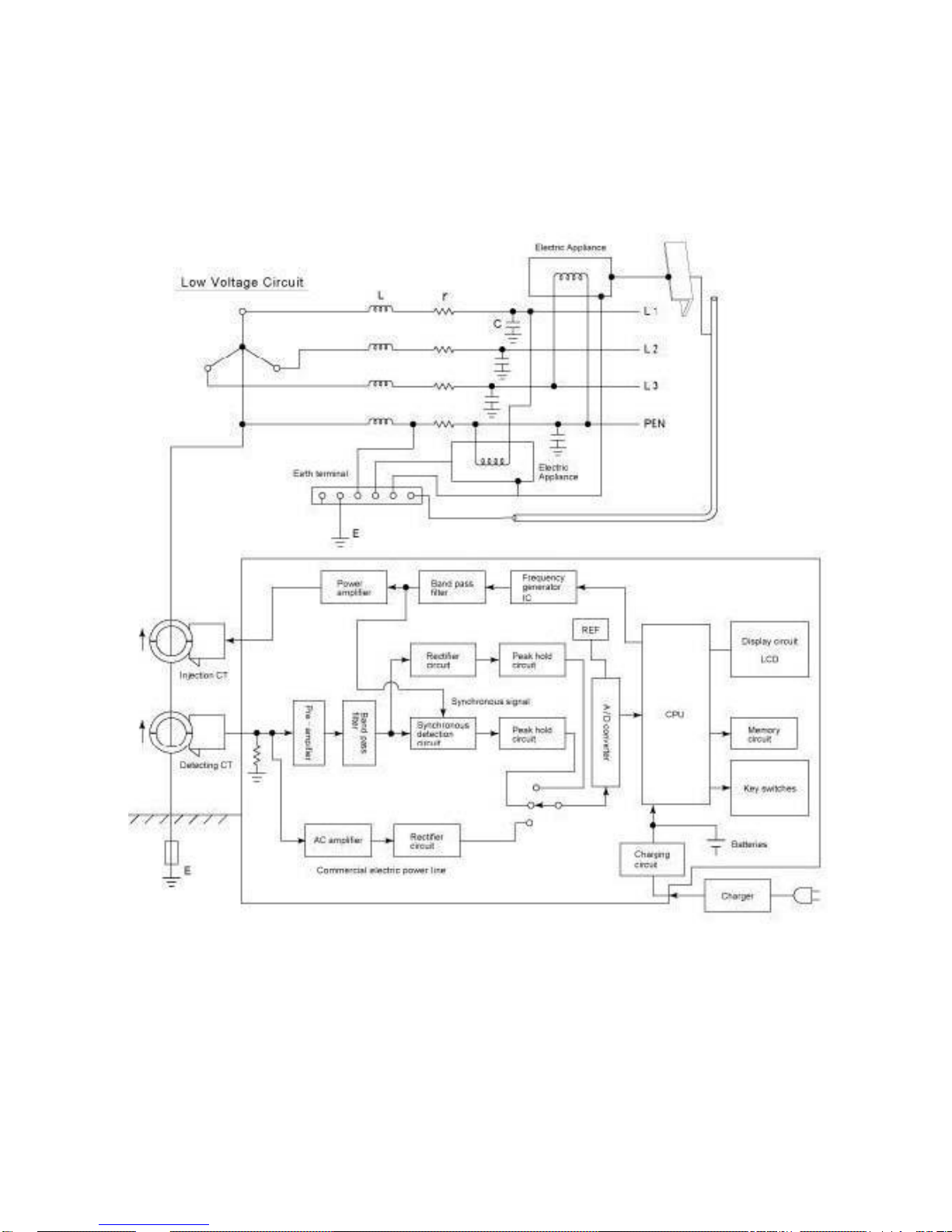
3. Measuring principle of clamp earth tester
Block diagram
- 4 -
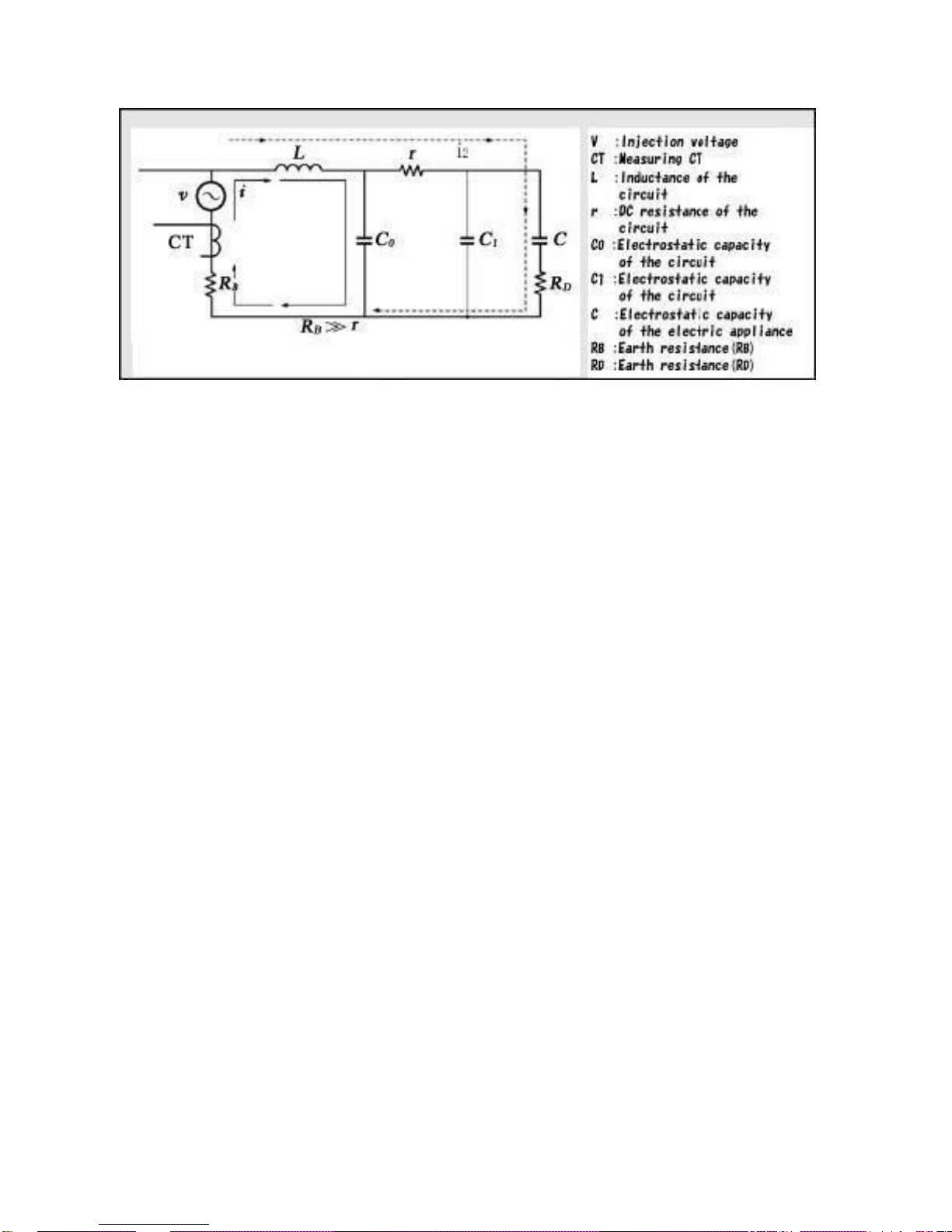
Equivalent circuit
The block diagram and equivalent circuit show the measuring principle of
CLAMP EARTH TESTER.
When the auto sweep signal (4kHz to 200kHz, 160mV p-p) is injected into the
circuit, the resonance phenomenon is caused at the certain frequency by
inductance (L) and electrostatic capacity (C0) or DC resistance (r) and
electrostatic capacity (C1) in the circuit, and the current flow (i) is caused. When
the resonance phenomenon is caused, the current flow (i) become maximum.
The injected current (i) into the circuit is proportional to the earth resistance (RB)
and this current (i) is measured by the measuring CT and used for the
computation of the earth resistance value (RB) with other calculation factors.
The resonance phenomenon is caused almost at 4kHz to 200kHz frequency in
our field test.
Note: If the resonance phenomenon is not caused in the circuit, the current
flow (i2) is caused and the measured resistance value become RB + RD
+Zc. This resistance value will be higher than the actual value
abnormally, or over range indication “OVER” will be displayed.
- 5 -
4. Specification
Measuring function : Earth resistance, AC current (Load & leakage)
A/D conversion : Dual slope integration mode
Safety standard : IEC 61010-1,IEC61010-2-032
Installation CATⅡ600V or CATⅢ300V
Sampling : Approx. 2 times/second for AC current
Measuring time : Approx. 30 second for earth resistance
Display : LCD16 letters/characters x 2 line with contrast
adjuster
Over range indication : “OVER” on LCD
Low battery indication : “B” mark on LCD
Data hold indication : “DH” mark on LCD for AC current measurement
Detection method : Synchronous detection
Accuracy (23°C ± 5ºC, 80% RH or less) :
Earth resistance (Earth current: Less than 1A)
Range Resolution Accuracy
Less than 10Ω 0.1Ω ±0.5Ω
10 ~ 50Ω 0.1Ω ±2.0Ω
50 ~ 150Ω 0.1Ω ±5.0Ω
150 ~ 200Ω 0.1Ω ±20Ω
Note:
Accuracy is specified by standard resistance with following test configuration.
- 6 -
Induction CT
Measuring CT

AC current
Range
Resolution
Accuracy
Maximum imput
200mA
0.1mA
2% rdg ± 8dgt
20A rms
2000mA
1mA
2% rdg ± 8dgt
20A
0.01A
2% rdg ± 8dgt
Measuring CT : φ34mm with 2.5m lead
Injection CT : φ34mm with 2.5m lead,
Auto sweep signal : 4kHz~400kHz
Signal injection level : Approx. 160mV p-p
Operating temperature : 0°C~40°C, <85%RH without condensation
Storage temperature : -10°C~60°C, <80%RH without condensation
Limitation of circuit voltage
: Less than AC 500V rms
Withstanding voltage : AC 3700V 1 minute (between CT core and CT
handle)
Insulation resistance : More than 100MΩ (between CT core and CT
handle)
Power supply : NiMH battery pack (1.2V x 5),
Battery charger : AC200V-240V(50/60Hz)
Auto power off function : Approx. 5 minutes later after power on
Power consumption : Approx. 350mA(Earth resistance measurement)
Battery life : Approx.450 times measurements under full charged
condition
(Subject to the times of charging & discharging)
(Size & weight)
Measuring CT : 90.5(W) x 165(H) x 38(D)mm, approx.460g
Injection CT : 90.5(W) x 165(H) x 38(D)mm, approx.440g
Main unit : 190 (W) x 140(H) x 42(D)mm, approx.800g
Accessories : Measuring CT………………..1
Injection CT………………….1
Battery charger……………....1
Carrying case………………..1
Subsidiary lead wire………....1
Instruction manual…………...1
Option : Lead wires for output terminal injection
(MET-LE)……………………...1
Outlet checker………………...1
- 7 -

5. Panel description
①Power switch : Power ON/OFF switch. After the final key
(POWER) operation, the power will be turned off
automatically 5 minutes later.
②Terminal for Injection CT : The insertion terminal for the injection CT.
(INJECTION) Connect red plug to the red terminal and black
plug to the black terminal.
③Terminal for measuring CT : The insertion terminal for the measuring CT.
(INPUT) Connect red plug to the red terminal and black
plug to the black terminal.
- 8 –

④Injection Terminal : for the signal injection not from the CT but from
(OUT PUT) the instrument body to disconnected terminals
of grounding line.
⑤Menu switch : Press this switch to return to the default display.
(MENU)
⑥Enter switch : Enter switch for the measuring function (earth
(ENT) resistance or current) selected by “UP” and
“DOWN” key. Also, used to start the earth
resistance measurement.
⑦Up, down key switch : Up and down key switch for the cursor of the
(UP, DOWN) display.
⑧Data hold switch : In AC current measurement, press this switch,
(DATA HOLD) “DH” mark is displayed and the displayed value
is held in the display. To release, press this
switch again.
⑨Display : LCD, 16 letters×2 lines
⑩Knob for display contrast : Contrast adjustment of the display.
(CONTRAST)
⑪Charger lamp : During battery charging, this lamp is always
lighted.
⑫Jack for charger : Input jack for charger plug.
(CHARGER)
- 9 -
6. Preparation before use
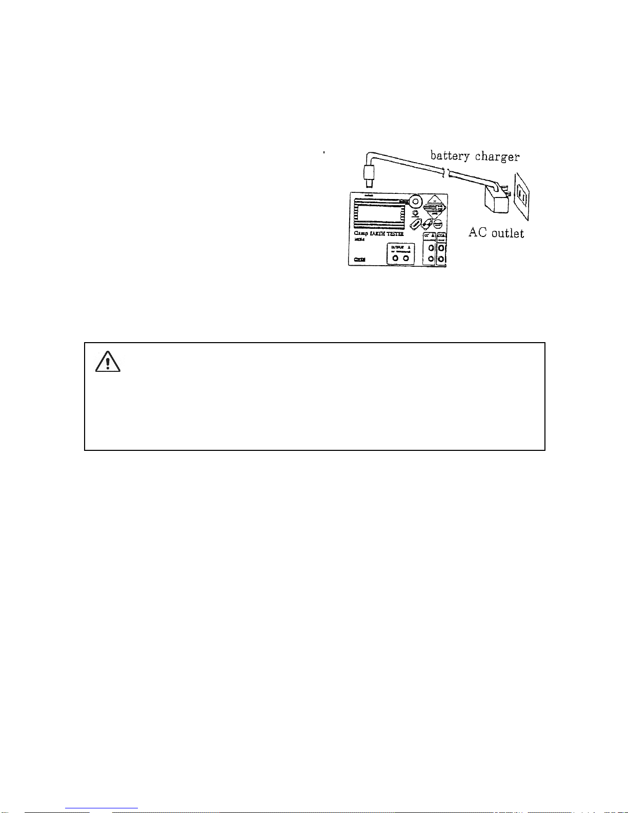
6-1. Battery charging
①Connect the charger plug to the jack
(CHARGER) of the instrument.
② Connect the charger to AC outlet
making sure that main voltage is
compatible (AC 200V~240V).
The charger lamp is turned ON and the
battery charging will start immediately.
③Charging of the battery takes 8 hours. Take care for over charging as the
charger lamp is not turned off even after full charging.
6-2. Rechargeable battery
NiMH battery is affected by various condition, and instrument operation time
may be affected by the charging/ discharging cycles and condition.
Precaution on charging of battery unused for a long period of time:
●Charge the battery at least once per 6 months, otherwise the battery power
will be exhausted.
●When the battery unused for a long period of time, the battery may not be
charged sufficiently.
●Keep the instrument at dry place.
- 10 -
CAUTION
●Use only charger delivered from manufacture or distributor of the test
instrument to avoid possible fire or electric shock.
●Do not charge alkaline battery.

●When the instrument is unused for a long period of time, the battery power will
be consumed by the self discharging.
●Avoid over charging, it may damage the battery life.
●Before using the instrument, charge the battery sufficiently.
●When instrument operation time is significantly reduced even after full
charging, replace the battery to new one, as the battery power is exhausted.
- 11 -

7. Operation
7-1. AC current measurements
①Press “POWER” switch, the
power is turned ON.
②Press “DOWN” key switch and
move the cursor to “Current”
position and press “ENT” key.
The tester is set to AC current
measurement mode as the
drawing.
③Connect the plug of measuring CT to the “INPUT” terminal.
④Measurement of load current (Max. AC 20A rms)
Clamp the conductor of the circuit
under test. Read the displayed value.
If the measured current is over range,
“OVER” is displayed.
If you made measurements in a dark
place or in a place where it is difficult to
see the readings, use “DATA HOLD”
switch.
Note: Clamp only one conductor of the
circuit to be measured.
⑤Measurement of leakage current
a. Measurement of grounding line
Clamp the grounding line and read the displayed value.
b. Measurement of single-phase or three phase electric circuit
To measure a leakage current in a single-phase or three phase circuit,
clamp the all active conductors (e.g. L1, N or L1, L2, L3, N). Read the
displayed value.
If you make measurements in a dark place or in a place where it is difficult to
see the readings, use “DATA HOLD” switch.
- 12 -
Note: Press “MENU” switch to the return to the initial display.
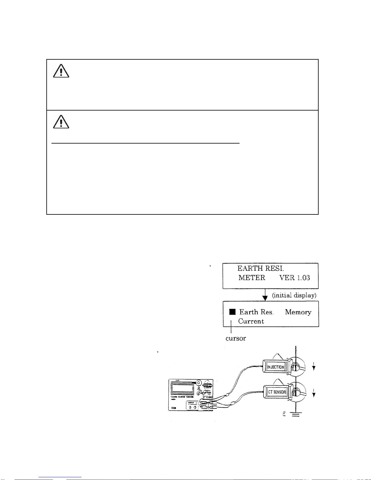
7-2. Earth resistance measurements
①Press “POWER” switch, the power is turned
ON.
②Connect the plug of injection CT to the
“INJECTION” terminal.
Connect the plug of measuring CT to the
“INPUT” terminal.
③Clamp the grounding circuit under test by
two CTs making sure that the arrow marks of
the CTs are same direction.
- 13 -
CAUTION
●The input frequency is limited to 100Hz for AC current measurements.
●The frequency value is not displayed for less than 3mA input.
WARNING
POSSIBLE ELECTRICAL SHOCK OR FIRE HAZARD:
●The applicable circuit voltage is limited to AC 500V rms. Before measurements, check the circuit voltage to be measured.
●Never make measurements for uninsulated conductors.
●Never fail to keep the maximum tolerable input. Do not apply more than
AC 20A rms to the CT.

CAUTION for earth resistance measurement
●Be sure to clamp the grounding line by both Injection CT and Measuring CT with
the same direction of the arrow mark. If incorrect direction is used, the
measuring error will be caused or abnormal value will be displayed.
●The grounding circuit with more than 1A current flow is not measurable.
● This instrument measures the earth resistance using the resonance
phenomenon caused by L (Inductance) and C (Capacitance) in the circuit.
When the measured resistance value is abnormal higher than the estimated
value, there is a possibility that the resonance phenomenon is not caused. In
such case, use a subsidiary jumper wire to create a good loop circuit.
④Set the cursor to “Current” position and
press “ENT” switch. The tester is set to AC
current measurement mode.
Check the current value of grounding circuit.
If the measured current value is more than
2A, the earth resistance is not measurable.
⑤Press “MENU” switch to return to initial
display.
⑥Set the cursor to “Earth Res.” Position and
press “ENT” switch .
⑦Set the cursor to “CT Out” position and
press “ENT” switch.
⑧“Measuring” indication begins to blink and
the measurement will start.
⑨After approx. 30 seconds, the measured
value will be displayed.
Note: ●Press “MENU” switch to return to the
initial display.
●When making the successive measurement, the waiting time is provided
for the stabilization of the circuit, but
this is not abnormal.
- 14 -

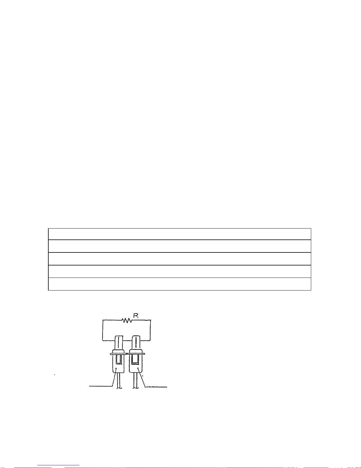
7-3. Measurement by TERMINALS Out mode
This TERMIANL Out mode means the measurement for earth resistance by
using output from the terminal of instrument body.
① Make power off of the circuit and disconnect the terminal of grounding line.
② Connect the lead wires as above drawing.
③ Press “POWER” switch once.
④ Set cursor at “Earth Res.” on the display.
⑤ Press “ENT” switch and set the cursor at “TERMINALS Out” on the display.
⑥ Press “ENT” switch once. “Measuring” sign appears on the display and
measurement starts.
⑦ After approx. 30 seconds, the measurement value is shown on the display.
* To get back the initial display from the measuring condition, press “MENU”
switch once.
- 15 -
CAUTION
●Locate the direction of red & black lead wires from the output terminals and the
Detection CT (CT SENSOR) as above drawing. In case of different direction
between lead wires and CT, the display will show “OVER” or wrong value.
●At the time of disconnecting the terminals of grounding line, make power off the
circuit.
●Lead wires are optional accessories. If you make them yourself, use wires with
φ2mm and make the length less than 1m.

8. Measuring example
The various measuring examples are showed in this chapter, however, these
are potential sources of error or incorrect test results due to the difference of the
earthing system and configuration in the field. It is important to remember the
key rules for the correct measurements.
●There must be a loop resistance to measure.
●The earth path must be in loop circuit.
●There must be L (inductance) and C (capacitance) in a loop circuit.
8-1. Electric installation
“ ” is shows the clamping point of the injection CT and the measuring CT.
- 16 -
●The clamping point (A) is used for the earth resistance measurement of the
metal case of high voltage appliance.
Connect the earth (A) to the known good earth by the subsidiary lead wire to
create the loop circuit.
●The clamping point (B) is used for the PEN earth resistance measurement.
In this case, simply clamp the measuring point by the injection CT and the
measuring CT.
●The clamping point (C) is used for the earth resistance measurement of the
lighting rod.
Connect a temporary link to the iron/steel frame of the building by the
subsidiary lead wire to create a loop circuit as the drawing.
Equivalent circuit
Earth resistance Earth resistance of the iron frame
of the lighting rod of the building
R2
R = R1 + R2
R1>R2
R≒R1
The instrument measures the whole loop resistance. If the earth resistance
(R2) is much lower than (R1), then the correct measurement is enabled.
●The clamping point (D) is used for the earth resistance measurement of the
accessible parts of low voltage appliance. In this case, simply clamp the
measuring point by the injection CT and the measuring CT.
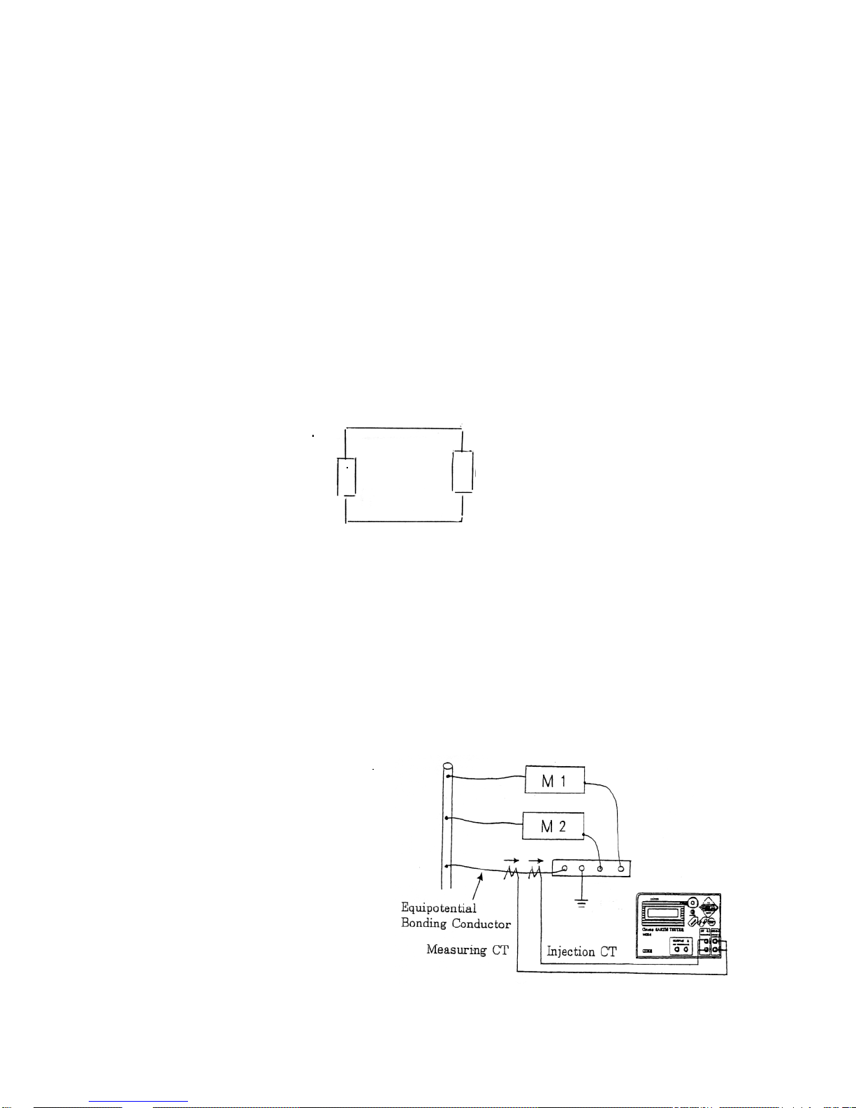
●The clamping point (E) is used
to check the poor connection
of bonding conductor for the
equipotential bonding system.
For poor connection, the higher
resistance value will be displayed.
- 17 -
R1

8-2. Earth resistance measurements for the outdoor appliance
(Air conditioner, etc.)
Measure the earth resistance at the
measuring point (ED) without the
connection of the subsidiary lead wire
at first. If the measured value is ex-
tremely high or “OVER” is displayed,
use the subsidiary lead wire to create
the loop circuit. Connect the earth
conductor to the earth terminal of the
building by the subsidiary lead wire,
then measure again.
Note: If needed, turn on the power of appliance. The electrostatic capacity of
the appliance will be increased.
8-3. Earth resistance measurements for multiple earth system
- 18 -

Equivalent circuit
Test result = RE+(R1//R2//R3// - - -)
Resistance of parallel connection (R1//R2//R3// - - -) < RE
Test result ≒ RE
The greater the number of parallel paths, the closer the measured value will be
to the actual earth resistance.
8-4. Earth resistance measurements for the earthing electrode
RE1 to RE4…..Individual earth resistances of tested earthing system
Test result = RE4+(RE3//RE2//RE1)
Resistance of parallel connection (RE3//RE2//RE3//) < RE4
Test result ≒ RE4
- 19 -
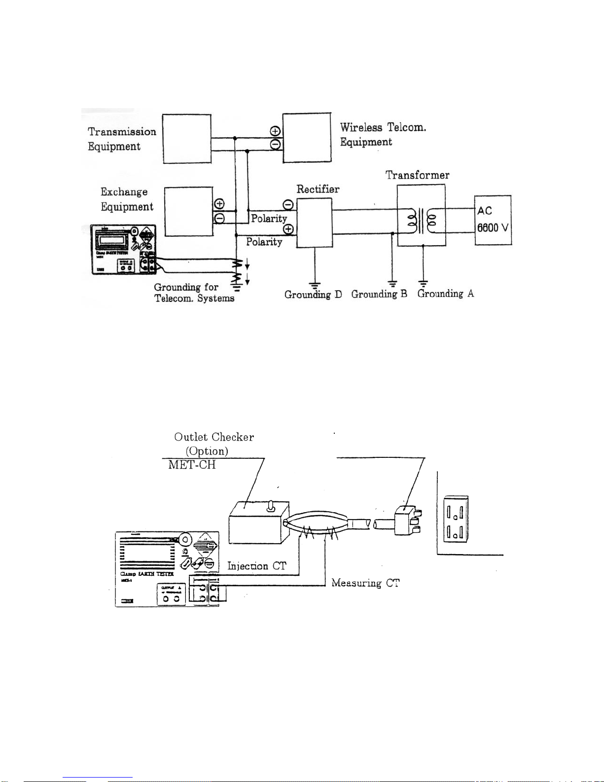
8-5. Earth resistance measurements for telecommunication system
8-6. Measurements for the earting connection of the outlet
MET-CH outlet checker (optional accessory) is used to check for mis-wiring of
the earthing connection of the outlet.
- 20 -
Connector with
earthing plug

8-7. Measurements for the active line
The earth resistance can be measured by clamping 2 CTs near at transformer
(point A or B) and near at the electrical loading part (motor, electric appliance, etc.
(point C. D. or E.).
8-8. Measurements where L (inductance) & C (capacitance) are low
Where L & C resonance has not been gotten, this instrument may show
“OVER” at the display. In this case, connect the objective grounding line (EA)
to other grounding lines (EB or ED) by the subsidiary lead wire and clamp 2 CTs
at the measuring point (EA). Even in the case of no resonance between L & C,
the multiple earth resistance can be measured.
- 21 -

9. Maintenance
When making requests for repair service, please bring the instrument directly to
the dealer. If this is impossible, however, send the instrument directly to our
sales office.
When mailing this instrument, always pack it in its original or equivalent packing
material and pack together with name, address, telephone number and the
warranty documentation.
●To ensure speedy and reliable repair, always include information of the type of
failure and cause.
●If required, always return accessories with the instrument.
●When contacting us, provide the model number and serial number of your
instrument.
10. Warranty
The instruments are subject to strict quality control. However, should the
instrument function improperly during daily use, you are protected by our 12
months warranty (valid only with invoice). We will repair free of charge any
defects in workmanship for our original defect. Any damage due to dropping,
incorrect operations and use, or repair/modification made by unauthorized
person are not covered by the warranty.
- 22 -
 Loading...