

Page 1

AC CURRENT
ANALOG CLAMP-ON TESTER
MODEL MCL-350
INSTRUCTION MANUAL
Thank you very much for selecting our digital AC clamp-on
tester.
This model is complex instrument and employ a very reliable
mechanical/electronic design.
Before you use your new instrument, read this Instruction
Manual completely and familiarize yourself thoroughly with
all functions. With proper use and care, your tester will give
you years of satisfactory service.
MULTI MEASURING INSTRUMENTS CO.,LTD.
Akihabara Murai Bldg. 7F, 1-26 Kanda Sakuma-cho,
Chiyoda-ku, Tokyo, Japan, 101-0025
TEL : +81-3-3251-7016 FAX : +81-3-3253-4278
Home Page : http://www.mutimic.com/
E-mail : [email protected]
Page 2

1. FEATURES
● High accuracy analog display with strong taut band meter.
● Meter lock function and data output for recorder.
● 3 years long battery life.
● Filter circuit for high frequency noise rejection.
2. △
!
WARNING
● Do not make measurements of power lines carrying more than 250V.
IN SOME CASES, POWER LINES MAY CARRY VOLTAGE SPIKES OF
SEVERAL TIMES OF THE NORMAL SUPPLY VOLTAGE.
THIS INSTRUMENT SHOULD BE USED TO MEASSURE POWER LINES.
*The terms of “POWER LINE” means the electrical circuit providing the power
to factories, buildings, etc.
● Before operating this instrument, familiarize yourself with all instructions
outlined in this manual.
● Always check to make sure that the function switch is set to the proper position.
● When making measurements, use CAUTION as dangerous voltages may be
present in normally safe areas.
● To avoid electrical shock, use CAUTION when working above 60V DC or 25V AC
rms.
Such voltages pose a shock hazard.
● Never make measurements with the case opened.
● Never fail to keep the maximum tolerable input.
● Never operate this instrument if it becomes wet, damp or has any liquid
condensation build-up on any part of the instrument.
● Never make measurements for uninsulated conductors or bus bars.
Page 3
Safety standard : Meets the requirements for double insulation to IEC61010-2-032,
IEC61010-1, installation CategoryⅢ600V phase to earth.
E.M.C. standard : The instrument meets EN61326 and EN61000.
Withstanding voltage : AC 5500V, 1 minute (between outer case and core of CT)
Jaw opening capability : 40mmφ
Current : AC 10mA/50mA/500mA/1A/5A/50A/500A
Accuracy :±3% of F.S.(50/60Hz)
Voltage : AC 0~500V
Accuracy :±3% of F.S.(50/60Hz)
Resistance : 0~1KΩ(50Ω center)
Accuracy :±3% of scale length
Analog data output for recorder: DC 100mV for full scale
Operating temperature : 0℃ to 40℃, <80%RH (non-condensing)
Strange temperature :‐10℃ to 60℃, <70%RH (non-condensing)
Power supply : 1.5V (“ AAA” size, R03) x2
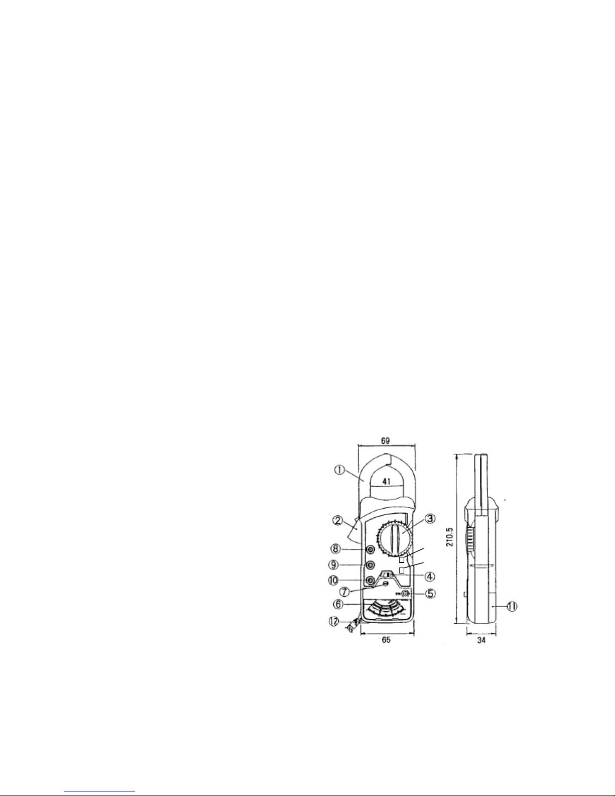
Size : 69(W)x210.5(H)x34(D)mm
Weight : Approx. 403g
Accessories : Carrying case…………..1
Instruction manual……1
Batteries…………………2
Test lead…………………1set
4. DIMENSIONS AND PANEL FUNCTION
① Current transducer (Jaw)
② Jaw opening lever
③ Range selector switch
④ Meter lock knob
⑤ Zero Ω adjustment knob
⑥ Pointer ⑬
⑦ Pointer zero adjustment screw ⑭
⑧ Input terminal (V) (Ω)
⑨ COM terminal
⑩ Terminal for recorder (REC)
⑪ Battery cover
⑫ Wrist strap
⑬ Filter Switch
⑭ Power/battery check switch
Page 4
5. METHOD OF MEASUREMENT
5-1. Preparation and Caution before Measurement
● Before measurements, be sure the meter lock function is released.
● Set the range selector switch to “~mA” or “~A” range and set the power switch
to “BATT”.
If the pointer indicates within the “BATT” mark, the batteries are usable. If the
pointer indicates outside the mark, the batteries are exhausted. In this case,
replace the batteries with new ones.
● Set the Zero (0) position of the pointer. If the position is incorrect, adjust it by the
pointer zero adjustment screw.
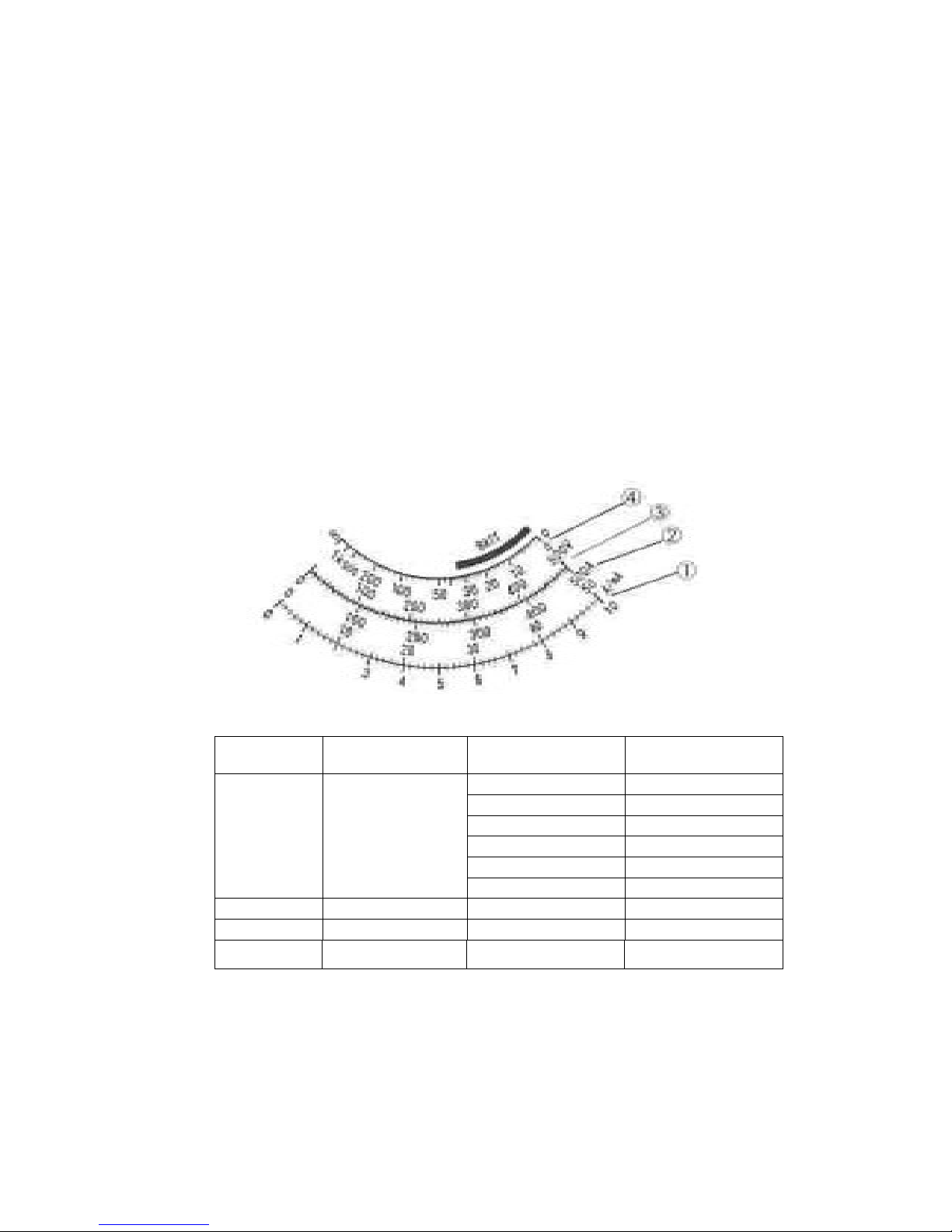
5-2. Reading Method of The Scale
No.
Function
Range
Multiplying
factor
①
Current
10mA
×1
50mA
×1
500mA
×10
1A
×0.1
5A
×0.1
50A
×1
②
500A
×1
③
Voltage
~500V
×1
④
Resistance
1KΩ
×1
Page 5
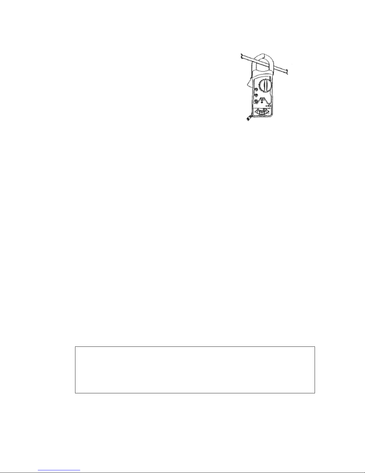
5-3. Measurement of AC Line Current L
① Set the power switch to “ON” position.
② Set the range selector switch to a range
appropriate to the current to be measured.
Start the measurement at top range and
then work down to lower range.
③ Clamp the conductor of the circuit at the
center of CT.
④ Read the current value on the current scale.
⑤ If you make measurements in a dark place
or in a place where it is difficult to see the
readings, use the meter lock function. Fig.1
Note : Clamp around only one conductor of the circuit to be measured. (See Fig.1)
5-4. Measurement of AC Leakage Current
5-4-1. Leakage current measurement for the grounding line
① Set the power switch to “ON” position.
② Set the range selector switch to a range appropriate to the current to be
measured.
③ Clamp the conductor of the circuit at the center of CT.
④ Read the current value of the current scale.
⑤ If you make measurements in a dark place or in a place where it is difficult to
see the readings, use the meter lock function
5-4-2. Leakage current measurement for the single-phase or three phase circuit
① Set the power switch to “ON” position.
② Set the range selector switch to a range appropriate to the current to be
measured.
③ To measure a leakage current in a single-phase electric circuit, clamp two
conductors together. Or clamp the three conductors together in the case of
the three-phase electric circuit.
④ Read the current value of the current scale.
⑤ If you make measurements in a dark place or in a place where it is difficult to
see the readings, use the meter lock function
△
!
CAUTION
● To avoid electrical shock or damage, the measurement is limited to the circuit
under 600V AC and 500A AC.
Page 6
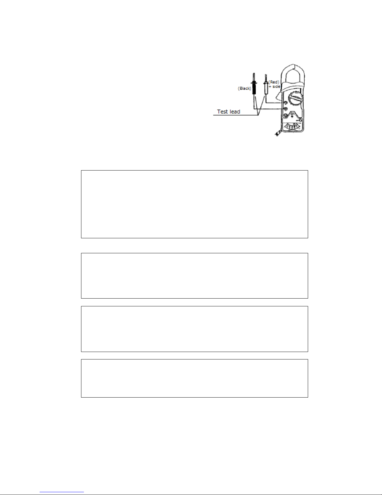
5-5. Measurement of AC Voltage
① Set the power switch to “ON” position.
② Connect the plug of red test lead into
the “V” terminal and the plug of black
test lead into the “COM” terminal.
③ Set the range selector switch to “~600V”
range.
④ Contact the tips of the test leads to the
circuit under test.
⑤ Read the voltage on the scale. Fig.2
Fig. 2
△!WARNING
Do not make measurements of power lines carrying more than 250V.
IN SOME CASES, POWER LINES MAY CARRY VOLTAGE SPIKES OF
SEVERAL TIMES OF THE NORMAL SUPPLY VOLTAGE. THIS
INSTRUMENT SHOULD NOT BE USED TO MEASURE POWER LINES.
* The term of “Power Line” mean the electrical circuit providing the power
to factories, buildings, and etc.
△!WARNING
POSSIBLE ELECTRICAL SHOCK. Do not make measurements if the case
is damaged or the rear case is removed. Remove all electrical inputs before
removing the rear case.
△!WARNING
POSSIBLE ELECTRICAL SHOCK or FIRE HAZARD. Do not expose this
tester to rain or moisture. Do not operate the tester in the presence of
flammable gases or fumes.
△!CAUTION
To avoid damage to the tester, disconnect test leads before changing
functions. Do not exceed the maximum input limits.
Page 7
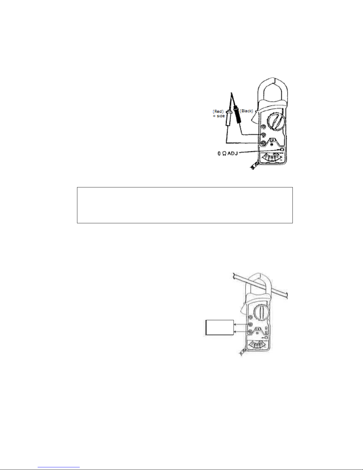
5-6. Measurement of Resistance
① Set the power switch to “ON” position.
② Connect the plug of red test lead into
the “Ω” terminal and the plug of black
test lead into the “COM” terminal.
③ Set the range selector switch to “Ω” range.
④ Short the tips of test leads and adjust the
pointer to indicate zero with the zeroΩ
adjustment knob.
⑤ Contact the tips of the test leads to the
circuit under test.
⑥ Read the resistance on theΩscale.
Fig.3
△!CAUTION
Be sure all voltage is turned OFF in the circuit before making resistance
measurement.
5-7. Measurement for External Recorder
DC 100mV/full scale analog signal is available
for the external recorder.
“REC” and “COM” terminal can be used for the
connection to the external recorder.
The input resistance of the recorder to be used
should be at least 1MΩ or more.
Input impedance > 1MΩ
Recorder
Page 8
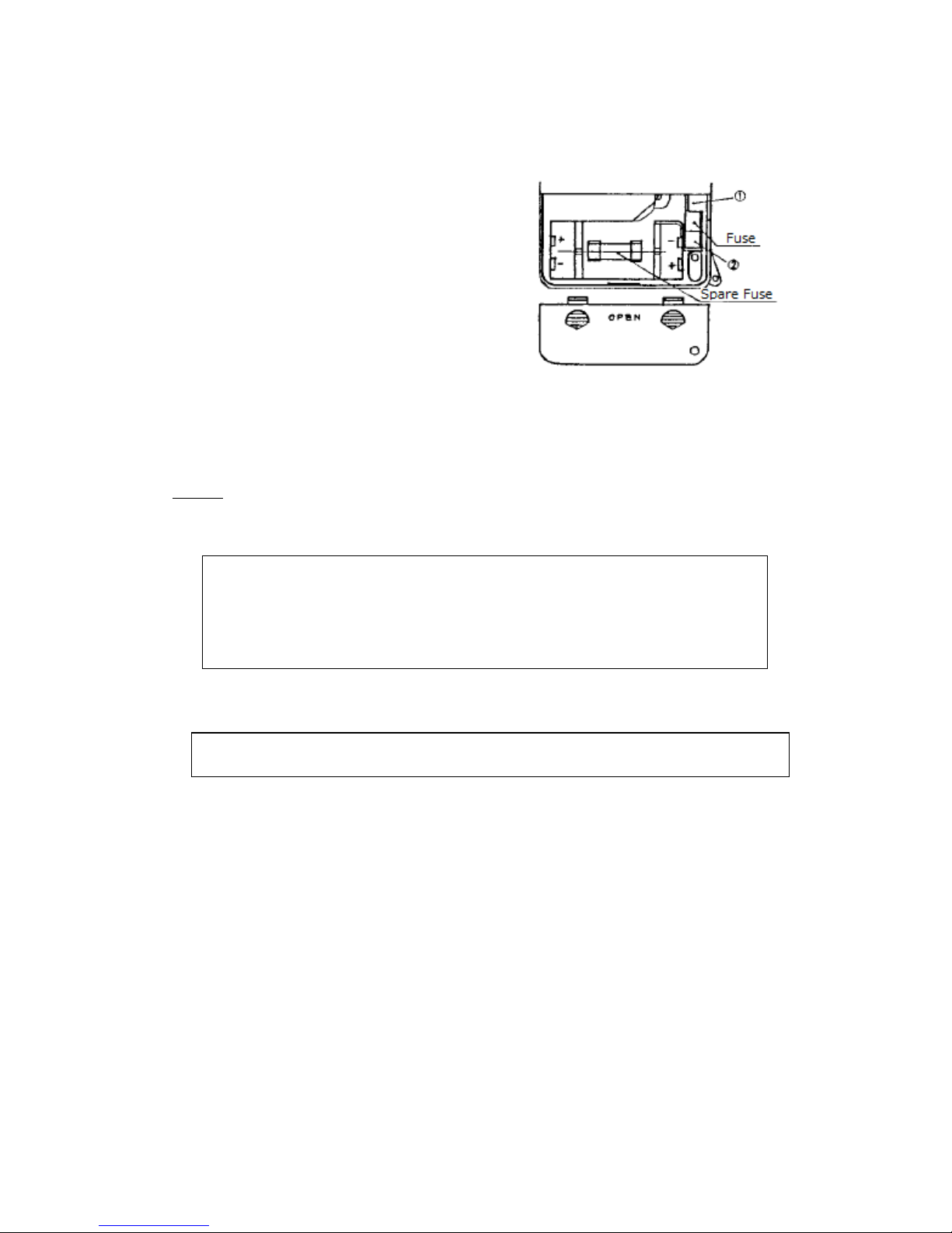
6. REPLACEMENT OF BATTERIES AND FUSE
(BATTERY REPLACEMENT)
1) Remove the fixing screw of battery cover by
+ driver on rear case and slide the battery
cover to the direction of arrow mark to open
battery case.
2) Take out 3 exhausted batteries.
3) Install new batteries (UM-4 or type AAA),
observing polarity.
4) Put back the battery cover to the original
position and tighten the fixing screw firmly.
(FUSE REPLACEMENT)
1) The fuse will be taken off when pressing ① point from up to down by the sharp
object (like thin tip of ballpoint).
2) Take out the spare fuse and insert it to ② point. Press the metal part at ① point
from down to up by the sharp object.
NOTE: It may cause breakage of the fuse glass part. Do not push the glass part by
the sharp object at the time of replacement.
△!WARNING
Before changing batteries or fuse, remove all electrical inputs.
Do not replace the batteries under the conditions of clamping CT to the
conductor and or inputting voltage to the terminals.
* Do not use the mixed batteries of new & old ones and or different kinds.
ΔCAUTION
● In case of not using the instrument for a long time, remove the batteries
and storage. Leakage of batteries may cause damage of instrument.
7. MAINTENANCE
When making requests for repair service, please bring the instrument directly to the
dealer. If this is impossible, however, send the instrument directly to our sales office.
When mailing this instrument, always pack it in its original or equivalent packing
material and pack together with name, address, telephone number and the warranty
documentation.
● To ensure speedy and reliable repair, always include information as the type of
failure and cause.
● If required, always return accessories with the instrument.
● When contacting us, provide the model number and serial number of your
instrument.
 Loading...