


UPS
Uninterruptible Power Supply
MD-1000I / MD-2000I / MD-3000I
V 1.0 User Manual
Authentic Manua
l

MD-1000I / MD-2000I / MD-3000I Imprint
Imprint
multimatic Vertriebs GmbH
This document is protected by copyright held by multimatic Vertriebs GmbH,
78667 Villingendorf, Germany.
This document is intended solely for the operator and operator's personnel.
Any reproduction, distribution, commercial or competitive use of its contents
(text, graphic representations, including figures, drawings, images schematics,
etc.), or making of them available to a third party, whether in part or in their entirety, without the express written permission of multimatic Vertriebs GmbH is
strictly prohibited.
multimatic Vertriebs GmbH
Im Wasen 2
D – 78667 Villingendorf
Germany
Phone: + 49 (0) 74 1 / 9292-0
Fax: + 49 (0) 74 1 / 9292-22
E-mail: kundenservice@multimatic-usv.de
Internet: www.multimatic-usv.de
Manual
Language: English
Issued: 10/2012
MD Series 2

MD-1000I / MD-2000I / MD-3000I Imprint
MD Series 3
multimatic Vertriebs GmbH reserves the right to make cosmetic or technical
design changes that may serve to improve the system, manufacturing process
or the product.

MD-1000I / MD-2000I / MD-3000I Table of Contents
MD Series 4
Table of Contents
1. Introduction ................................................................................................................ 6
1.1 Forward ........................................................................................................................ 6
1.2 Scope of Application .................................................................................................... 7
1.3 Availability of Manual ................................................................................................... 7
1.4 Symbols Used in Manual ............................................................................................. 7
1.5 Information Liability .................................................................................................... 11
1.6 Warranty Terms ......................................................................................................... 11
1.7 Transport and Storage ............................................................................................... 13
1.8 Installation Site........................................................................................................... 14
2. Safety Instructions................................................................................................... 16
2.1 Introduction ................................................................................................................ 16
2.2 Compliant Use............................................................................................................ 16
2.3 Avoiding Personal Injury and Property Damage ........................................................ 17
2.4 Environmental Protection ........................................................................................... 17
2.5 Power Connection...................................................................................................... 18
2.6 Operation ................................................................................................................... 19
2.7 Handling Batteries...................................................................................................... 19
2.8 Maintenance, Service and Malfunction ...................................................................... 20
3. Explanation of USB Function.................................................................................. 22
3.1 Front Panel................................................................................................................. 24
3.2 Rear Panel ................................................................................................................. 29
3.3 Installation Changes................................................................................................... 40
3.4 Operational Modes and Voltage Settings................................................................... 46
4. Storage and Unpacking ........................................................................................... 50
4.1 UPS Storage .............................................................................................................. 50
4.2 Unpacking the UPS.................................................................................................... 50
5. System Function ...................................................................................................... 52
5.1 UPS Schematic Diagram ........................................................................................... 52
5.2 UPS Operating Mode - Normal .................................................................................. 54
5.3 Overload..................................................................................................................... 56
5.4 Inverter ....................................................................................................................... 57
5.5 Inverter - Excessive Internal Temperature ................................................................. 58
6. UPS Installation and Hook-Up ................................................................................ 60
6.1 UPS Connection......................................................................................................... 60
6.2 UPS Communication Interfaces ................................................................................. 62
6.3 Equipment Connection Sequence.............................................................................. 63

MD-1000I / MD-2000I / MD-3000I Table of Contents
MD Series 5
7.
System Operation and Display ................................................................................64
7.1 UPS Modes and Display Messages ...........................................................................64
7.2 USP User Instructions.................................................................................................64
7.3 Replacing Batteries.....................................................................................................72
8. Trouble Shooting Guide ...........................................................................................77
9. Software.....................................................................................................................81
10. Maintenance and Service .........................................................................................82
10.1 Determining the Back-up Capacity .............................................................................82
10.2 Service Log .................................................................................................................84
10.3 Service Hotline............................................................................................................85
10.4 Maintenance and Service Contracts...........................................................................85
11. Technical Information...............................................................................................86
11.1 Included Components and Accessories .....................................................................89
11.2 Wear Parts ..................................................................................................................91
12. Declaration of Conformity........................................................................................92

MD-1000I / MD-2000I / MD-3000I Introduction
1. Introduction
1.1 Forward
Dear User,
You will find this manual to be of great assistance. For this reason, we urge
you to read it carefully before operating the unit.
It will provide you with information and instructions necessary to effectively and
responsibly operate the uninterruptible power supply. It also offers advice on
what to do in the event of malfunction. In addition, you'll find transport, storage
and installation information here.
Guidelines presented in this document solely concern the supply of uninterrupted power. The installation and personnel performing the installation are
subject to applicable national and local electrical codes and regulations.
Modification to contents of this manual may be necessary from time to time to
accommodate technical changes. We have gone to great lengths to ensure the
contents' accuracy and ease of comprehension. However, we would be grateful
if you notify us of any errors or inaccuracies you find.
We accept no liability for errors or consequential damages resulting from those
errors.
The uninterruptible power supply unit has been designed and built to protect
sensitive electrical equipment against failure caused by poor power quality or
power failure.
Read this manual carefully and completely, while paying careful attention
to the safety guidelines!
Your company's technical support or a member of our team will be glad to assist you with your questions concerning this unit.
Sincerely,
multimatic Vertriebs GmbH
MD Series 6
MD-1000I / MD-2000I / MD-3000I Introduction
MD Series 7
1.2 Scope of Application
al
al
The explanations found in this manual apply exclusively for the
uninterruptible power supply
as described in the Technical Information section as an entire system and for
modules, subsystems and individual parts designed and built by multimatic
Vertriebs GmbH.
( 11. Technical Information)
1.3 Availability of Manu
Make sure this manual is always in proximity to the UPS to ensure it is there
when and where needed.
1.4 Symbols Used in Manu
The abbreviation UPS appearing in this manual stands for uninterruptible
power supply.
Read this document carefully to become familiar with the product before using
it.
Keep the manual handy at all times, so you can reference it when needed.
Pass the manual on to future users of the product.
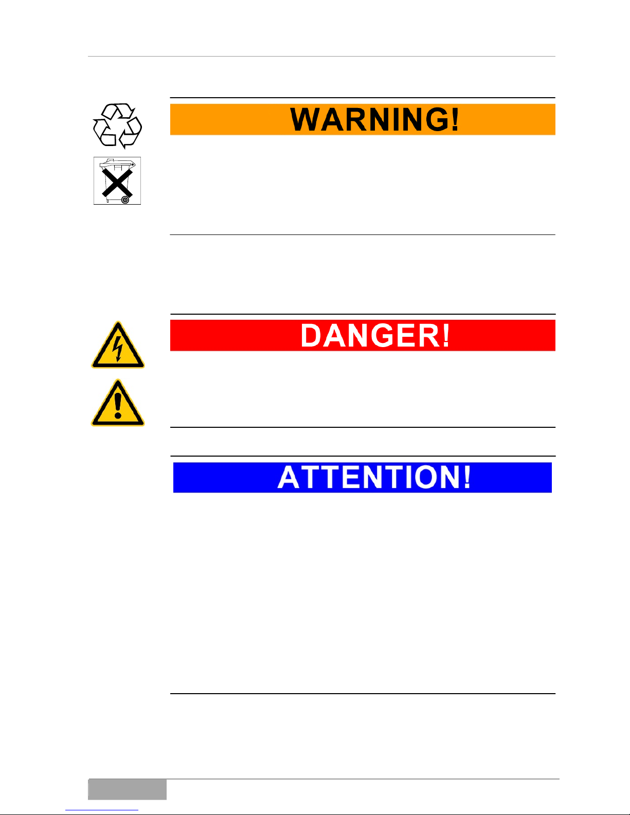
1.4.1 Warning levels
Text in which "DANGER!" appears warns you of dangers. If you neglect
preventative measures, serious (irreversible), life-threatening injuries or
death will occur!
MD-1000I / MD-2000I / MD-3000I Introduction
Text in which "WARNING!" appears warns you of dangers. If you neglect
preventative measures, serious (irreversible), life-threatening injuries or
death may occur!
Text in which "CAUTION!" appears warns you of dangers. If you neglect
precautionary measures, slight or moderate injuries may occur!
Text in which "ATTENTION!" appears contains very important information
about situations in which neglecting preventative measures can result in
damage to the product, its function or objects in its vicinity.
This symbol indicates information that is especially useful or important.
MD Series 8
MD-1000I / MD-2000I / MD-3000I Introduction
1.4.2 Warning pictograms
1.4.2.1 Hazard vicinity warning
Generally hazardous area!
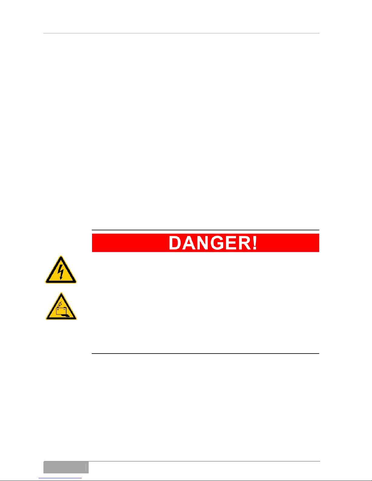
1.4.2.2 Specific warnings
Hazardous voltage!
Battery hazard!
1.4.3 Mandatory action symbols
Take action as stated in information and instructions provided in documents and by pictograms.
Disconnect via all-pole disconnect prior to beginning work!
MD Series 9

MD-1000I / MD-2000I / MD-3000I Introduction
1.4.4 General symbols
This symbol indicates actions that you are required to perform.
- This hyphen introduces items in a list.
This arrow indicates a cross reference.
To keep things easily understandable, you'll find cross references directing
you to other chapters on occasion.
Example: UM, 2 Safety Instructions
This tells you to refer to User Manual,
Chapter 2 in the manual.
If the cross reference refers to a page, figure or item number, it will appear at
the end of the cross reference.
Example: Fig. 4 - 4, Item 1
This directs you to Chapter 4 in the User Manual, Figure 4, Item 1.
(3) Numbers in parentheses refer to items found in figures.
Must be recycled
Indicates components or assemblies that are subject to electronic waste disposal ordinances and regulations.
Indicates assemblies or parts that you are prohibited from disposing of as or in
regular household rubbish.
Prerequisite or something you must do:
The DC disconnect switch is switched to OFF.
MD Series 10

MD-1000I / MD-2000I / MD-3000I Introduction
1.5 Information Liability
This manual must be read by everyone, including
– users
– maintenance and cleaning personnel
– those responsible for disposal and recycling
of the device. They must understand and follow every instruction and all guidelines provided therein.
multimatic Vertriebs GmbH accepts no liability for damages caused by
uninstructed or insufficiently instructed personnel!
1.6 Warranty Terms
Your receipt is your proof for your initial purchase. Make sure you keep in a
safe place, because you will require it for warranty claims. In the event you
transfer the product to the possession of another user, the warranty shall remain in effect. The new user requires the receipt and this explanation.
We guarantee the product you have purchased to be in good functioning order
and technically as described in the enclosed documents when it left our premises.
The warranty period for custom-built or -configured units complies with the legislatively-regulated minimum.
This warranty does not apply in the following instances:
Defects caused by shipping, accident, natural catastrophes, abuse, vandalism,
improper use, inappropriate maintenance or improper repair by an unqualified
third party.
– Modifications performed by unauthorized persons, incorrect operation,
other devices or equipment, improper installation or any modifications not
authorized by multimatic Vertriebs GmbH
– Improper use, for example plugging the device into unsuitable sources of
electrical power, attempts to overload the UPS, use in an unsuitable environment.
– Disregard of the instructions in provided documents.
MD Series 11

MD-1000I / MD-2000I / MD-3000I Introduction
– Incompatibility of product due to technical changes or regulations that oc-
cur after purchase.
– Incompatibility or malfunction caused by product components not installed
by multimatic Vertriebs GmbH.
– Effects caused by normal product wear and tear.
– Defects caused by external apparatuses or devices.
Warranty periods for parts repaired or replaced under the unit's original warranty expire when the unit's warranty expires.
Units returned without accessories will be replaced without accessories. To be
accepted, products returned must be shipped in their original packages.
In general, the warranty does not cover shipping costs.
The customer is responsible for repair and replacement costs and multimatic
Vertriebs GmbH is not liable for damages, whether direct, accidental, unique or
consequential damage, even if caused by negligence or other acts.
multimatic Vertriebs GmbH gives neither explicit nor implicit guarantees on
this product, its quality, performance, saleability or suitability for a specific purpose. In some countries, the exclusion of implicit guarantees is not permitted
by law. In such instances, the validity of all express and implicit guarantees is
limited to the warranty period. When the warranty expires, all guarantees lose
their validity. In some countries, law does not permit a limit of the period of validity of implicit guarantees, so that the limitation described above does not take
effect.
MD Series 12

MD-1000I / MD-2000I / MD-3000I Introduction
MD Series 13
1.6.1 Liability limitations
Claims for compensation are excluded, unless based on wrongful intent or
gross negligence on the part of multimatic Vertriebs GmbH or its employees.
Liability as per product liability laws remains unaffected. Under no circumstances are we liable for:
– Third-party claims filed against you the purchaser for losses or damages.
– Loss of or damages to your records or data or the costs for the recovery of
these data.
– Economic damages (including profit or savings losses) or other related
damages, even if we were informed in advance of the possible occurrence
of such damages.
Under no circumstances, is multimatic Vertriebs GmbH liable for any accidental, indirect, unique, consequential damages or any other damages (without
exception, whether loss of profit, business activity or business, business records, data or information or any other losses) that occur through the use of
this product or in any conjunction with the product, whether due to a contract,
damage claim, negligence, strict liability of claims, even if multimatic Ver-
triebs GmbH was informed in advance of the possibility of such an occurrence. This exclusion also includes any liability that could occur due to thirdparty claims on the original purchaser.
In some countries, law does not permit the limitation of accompanying or related damages or consequential damages, so that the explanation above does
not take effect.
1.7 Transport and Storage
The UPS appliance shall be packed in its original packaging when transported
to its site of operation, when returned to the seller or in the event it is moved to
another site of operation.
The original package offers no protection in the event the package falls or is
dropped. For this reason, products that have fallen must be examined by mul-
timatic Vertriebs GmbH prior to operation.
Do not store or transport this device with its top upside down.

MD-1000I / MD-2000I / MD-3000I Introduction
1.8 Installation Site
Do not install in an area where flammable vapours are present, for example, petrol/gasoline, storerooms, areas in which combustion-driven motors operate, etc.
The UPS appliance is designed for operation in ventilated rooms with ambient
temperatures of 0 to 40° C.
If the UPS is subject to significant and quick temperature changes, condensation may develop. Should this be the case, it is necessary to give the unit at
least 2 hours to acclimate.
Never place, install or operate the UPS in a damp environment. Keep fluids at
a suitable distance away from the unit.
Do not place, install or operate the UPS near a source of heat.
You may install the UPS in either a horizontal or a vertical position. Vertical installation requires you use the feet; horizontal requires the use of a 19-inch
rack.
Install and maintain a minimum distance of 10 cm from the appliance's back
and front to other objects to ensure the UPS has enough air circulation to prevent high temperatures. Make sure the air vents are free of blockage through
paper or other materials that might be stuck in the intake openings.
MD Series 14

MD-1000I / MD-2000I / MD-3000I Introduction
MD Series 15

MD-1000I / MD-2000I / MD-3000I Safety Instructions
2. Safety Instructions
2.1 Introduction
The UPS is designed and built in accordance with technical guidelines
and regulations for uninterruptible power supply equipment. It and its
components, modules and assemblies individually and as an entire system meet the current safety code requirements and comply with the EU
2006/42/EG Machinery Directive.
The UPS is operationally safe, provided the user uses this appliance pursuant to said codes and regulations and the safety instructions, guidelines and precautions stated in this user manual.
2.2 Compliant Use
Use the UPS and its components solely for their intended purpose, which
is the temporary supply of electrical power to electrical devices (230 V
AC) while, together, not exceeding the total nominal capacity.
Any other use or use that exceeds said use is not in accordance with the
intended purpose and may lead to personal injury or equipment damage!
Improper uses
The UPS is not intended for use:
– in explosive,
– dust-laden,
– radioactively or
– biologically or chemically contaminated atmospheres.
The
UPS is Class A equipment. This product may produce electromagnetic interference. If this is the case in living areas, the user may be required to implement appropriate corrective measures.
MD Series 16

MD-1000I / MD-2000I / MD-3000I Safety Instructions
MD Series 17
2.3 Avoiding Personal Injury and Property Damage
n
Read the user manual carefully, making sure you understand the product.
Pay careful attention to the information and instructions concerning the installation, pre-operation and initial operation of the unit.
Operate this product only properly and in accordance with the intended use
and the technical specifications provided.
Perform only the service and maintenance work that is described in the provided documents. Follow the stipulated actions and steps as described. Use
only original parts obtained from multimatic Vertriebs GmbH.
2.4 Environmental Protectio
When your product has reached the end of its service life, send it back to multimatic Vertriebs GmbH and we'll dispose of it compliant with environmental
protection laws.
MD-1000I / MD-2000I / MD-3000I Safety Instructions
2.5 Power Connection
Use only an outlet socket with earthed/grounding contact or, if using a
terminal block, connect protective conductor. Under no circumstances,
operate the UPS without an earth/ground connection.
The socket you use must be readily accessible and close to the UPS unit.
If using a permanent connection, keep the cable length as short as possible.
If operating with a generator, make sure not to reverse the connection's
polarity.
Use only a VDE- and CE-approved power cable between the socket and
the UPS. If wiring the UPS via permanent/direct connection, use a cable
with suitable approval rating.
Use only a VDE- and CE-approved power cable to connect the protected
equipment to the UPS. If wiring protected equipment via permanent/direct
connection, use a cable with suitable approval rating.
Make sure the circuit breaker to protect the connected equipment always
comes right before the connected/protected equipment; never rely on a
central fuse placed in front of the UPS.
Do not use the UPS to power household appliances and power tools,
such as portable heaters, vacuum cleaners, drills, hair dryers, toasters,
etc.
Never connect to the UPS unit electrical equipment that could overtax it
(laser printer, etc.).
Make sure the total current amperage of all the equipment connected to
the UPS does not exceed 3.5 mA.
Keep power cables as short as possible and make sure they are installed
code-compliant, including installation that avoids stumbling, exposure to
heavy weight or sharp objects, etc.
Use only a VDE- and CE-approved power cable with suitable gauge to connect
the protected equipment to the UPS. Make sure the circuit breaker to protect
the connected equipment always comes right before the connected/protected
equipment; never rely on a central fuse placed in front of the UPS. Never connect to the UPS unit electrical equipment that could overtax it (monitor inrush
current).
MD Series 18
MD-1000I / MD-2000I / MD-3000I Safety Instructions
2.6 Operation
Before connecting equipment to the UPS outlet, you must perform the initial
configuration. Very important here is the output voltage going to the connected
equipment.
The UPS device contains an energy storage facility (battery), which means the
outlet can carry electricity even if the USP is not connected to a power supply.
To switch the UPS off completely, first, hold the OFF button for longer than 3
seconds and wait for the UPS to shut down. Next, disconnect the power supply
connector from the device. Make sure no liquids or foreign materials gain access to the UPS' interior. To protect the UPS, it is best to avoid lasting output
loads greater than 80%. The output load shown on the display is only a guide.
To determine the actual output load, extra measurements with a suitable device are necessary.
2.7 Handling Batteries
Attention! Danger of shock and burns
Batteries can produce electrical shock and short circuit currents that are
capable of burning tissue.
Keep unqualified persons away from batteries.
Do not place batteries in or around sources of heat, e.g. fire, because
they may explode!
Do not open or destroy batteries. The electrolyte is extremely hazardous
for persons and the environment (danger of burns to eyes and skin; poison).
MD Series 19
MD-1000I / MD-2000I / MD-3000I Safety Instructions
MD Series 20
Defective batteries must be disposed of compliant with environmental
protection regulations.
Under no circumstances ever dispose of batteries with regular household
garbage.
Follow local disposal regulations.
2.8 Maintenance, Service and Malfunction
Attention! Danger of shock
Even after, you have turned off the power switch or broken the circuit to
the battery, UPS components may still carry high voltage.
Only qualified persons with the required knowledge of precautionary
measures are to perform and supervise work on batteries.
Keep unqualified persons away from batteries.
The following precautionary measures are necessary when working on
UPS devices and batteries:
– Remove wristwatches, rings and other metal objects
– Use only insulated tools that are compliant with electrical regulations
and guidelines
– Wear protective glasses/goggles, gloves, face protection
– Do not dismantle the UPS

MD-1000I / MD-2000I / MD-3000I Safety Instructions
MD Series 21

MD-1000I / MD-2000I / MD-3000I Explanation of USB Function
3. Explanation of USB Function
This manual will provide you with fundamental information about single-phase
online UPS systems, specifically how they function, use of the various functions and what you are to do in the event of malfunction. In addition, this manual contains information about transport, storage, handling and installation of
UPS systems.
Guidelines presented in this document solely concern UPS requirements. The
installation and personnel performing the installation are subject to applicable
national and local electrical codes and regulations. Modification to the contents
of this manual may be necessary from time to time to accommodate technical
changes. We have gone to great lengths to ensure the contents' accuracy and
ease of comprehension. However, we would be grateful if you notify us of any
errors or inaccuracies you find.
We accept no liability for errors in this user manual or consequential damages
resulting from those errors.
The UPS system (uninterruptible power supply) has been designed and built to
protect sensitive electrical equipment, such as computers, workstations, electronic money handling machines, important business devices, telecommunication systems, process controls, etc., against failure caused by poor power quality or power failure. Such sensitive systems require comprehensive protection
against electrical failure. Often, the failure may be caused by events outside
the system (e.g. thunderstorm, breakdown of operations) or interference
caused by nearby equipment (such as motors, air conditioners, machinery,
welding, etc.).
Power supply malfunctions are typically:
– Quick and slow line voltage peaks, fluctuation
– Power failures
– Fast or slow frequency peaks and fluctuations
– Power line interference or transients
The UPS s
ystem monitors the abovementioned power supply parameters and
protects the connected devices via suitable actions (e.g. switch over in the
event of power surges, over voltage or drops).
The UPS' mode of installation modifies easily from upright, using the provided
legs, to horizontal in a 19" rack and vice versa.
You'll find instructions for changing the installation mode in the chapter dedicated to this subject ( 3.3 Changing Installation Mode).
MD Series 22

MD-1000I / MD-2000I / MD-3000I Explanation of USB Function
The advanced in
sulated-gate bipolar transistor (IGBT) technology and industrial quality design ensure the UPS will operate efficiently and dependably,
even under tough conditions.
A powerful CPU integrates all the power stages, control and communication
functions required to provide maximum protection and UPS function, including
monitoring of the energy saving management, remote control and selfdiagnostics. The unit's cleverly designed CPU communication system permits
remote computer control with full functionality from any computer environment
via standard RS-232 port.
The UPS' wide input voltage tolerance (120V~288V) permits under or over
voltage correction without use of the battery, helping to extend the battery's
operating life.
The cold start function ensures the UPS will start even in the event of a power
outage.
A battery management system monitors the battery's charge to determine
when the battery draw will cease, another feature that prolongs the battery's life
span.
Advanced input voltage control minimizes the reactive power factor and increases efficacy. The unit's active power factor correction (PFC) delivers a
power factor (PF) of greater than 0.99, which translates into superb energy efficiency.
The adjustable bypass input voltage tolerance (low/high) prevents the unit from
switching to the bypass mode in the event of low or over voltage.
Large choices of output voltages (200/208/220/230/240) permit the use of different voltage systems.
This UPS device was designed and built to comply with international electromagnetic standards.
MD Series 23
MD-1000I / MD-2000I / MD-3000I Explanation of USB Function
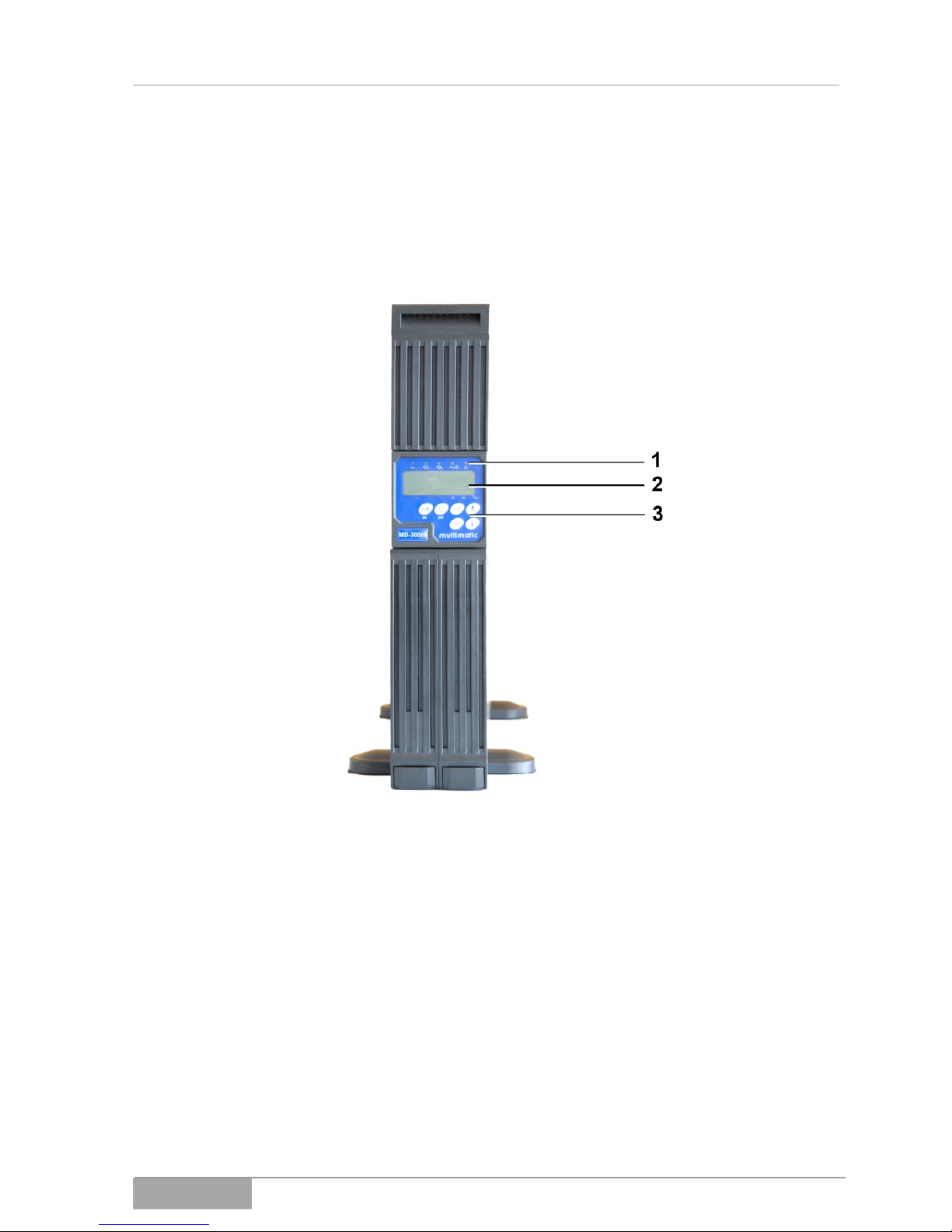
3.1 Front Panel
You'll find all the display and control elements you need for normal use on the
UPS' front panel.
1 Status LEDs
2 LCD display
3 Buttons
Fig. 3-1 - 1 MD-1000I / MD-2000I / MD-3000I front view
MD Series 24
MD-1000I / MD-2000I / MD-3000I Explanation of USB Function
3.1.1 LCD display (optional)
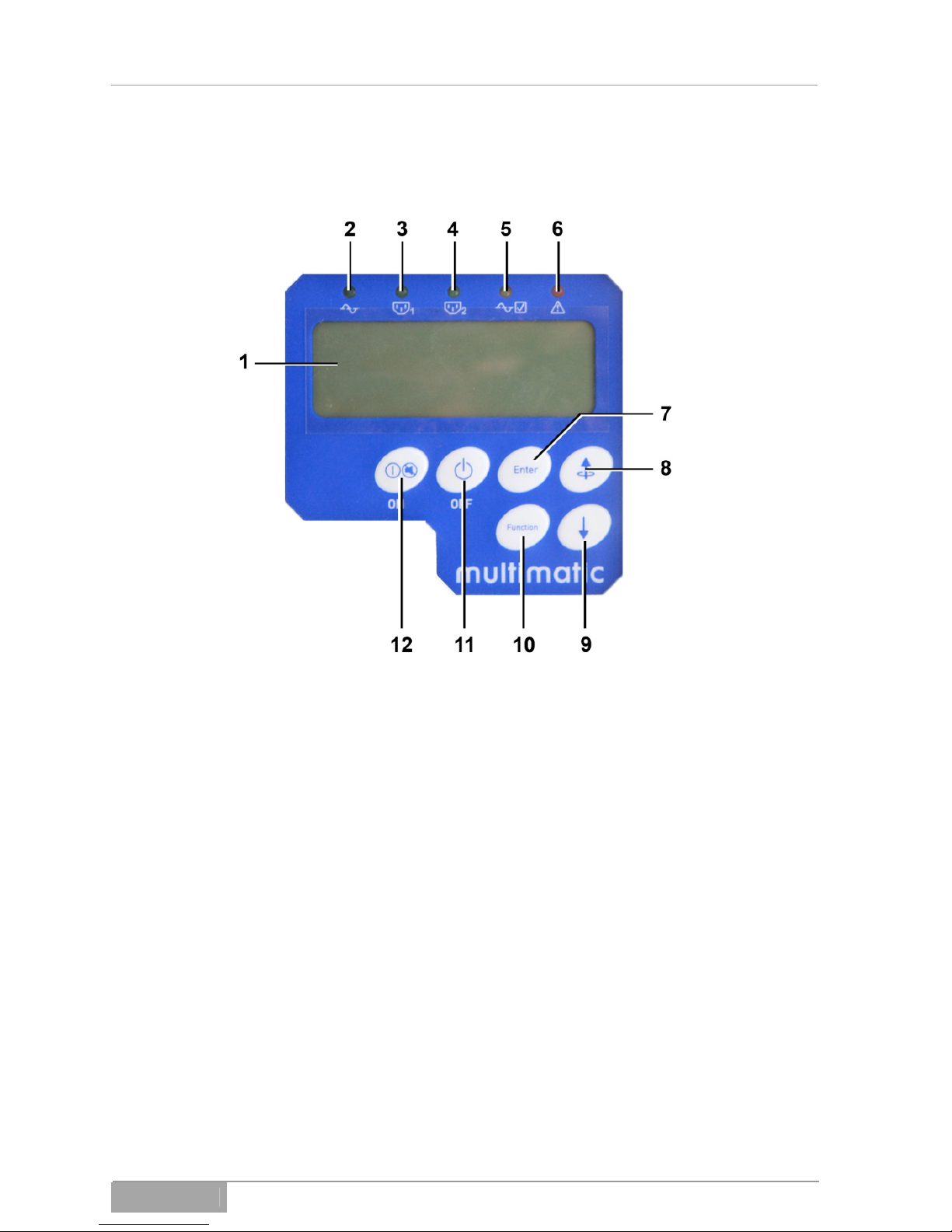
1 LCD display
2 LED input voltage
3 Programmable output 1 LED
4 Programmable output 2 LED
5 Bypass LED
6 UPS system fault LED
7 Select
8 Scroll up
9 Scroll down
10 Other functions
11 UPS off
12 UPS on; mute alarm
Fig 3-1 - 2 Front panel interfaces
MD Series 25

MD-1000I / MD-2000I / MD-3000I Explanation of USB Function
3.1.2 Keypad
UPS On / Alarm mute (12)
functions:
Turns UPS on.
Deactivates audible alarm.
UPS off (11)
functions:
Turns UPS off.
Other functions (10)
functions:
Buzzer on/off
Battery test
Bypass power
Output frequency synchronization window
Inverter output voltage
UPS operating mode
Output voltage fine adjustment
Scroll down (9)
functions:
Scrolls down menu by pages
Scroll to previous page / Change UPS settings (8)
functions:
Scrolls up menu by pages
Changes UPS settings
Select (7)
functions:
Verifies selection
MD Series 26

MD-1000I / MD-2000I / MD-3000I Explanation of USB Function
Manual bypass
To activate the manual bypass, proceed as follows:
Press buttons 12 and 8 simultaneously for about 3 seconds, to change from
normal operation to bypass mode.
The LED bypass indicator will blink constantly and an audible signal will sound.
Press buttons 12 and 8 simultaneously for about 3 seconds, to change
from bypass mode to normal operation.
MD Series 27
MD-1000I / MD-2000I / MD-3000I Explanation of USB Function
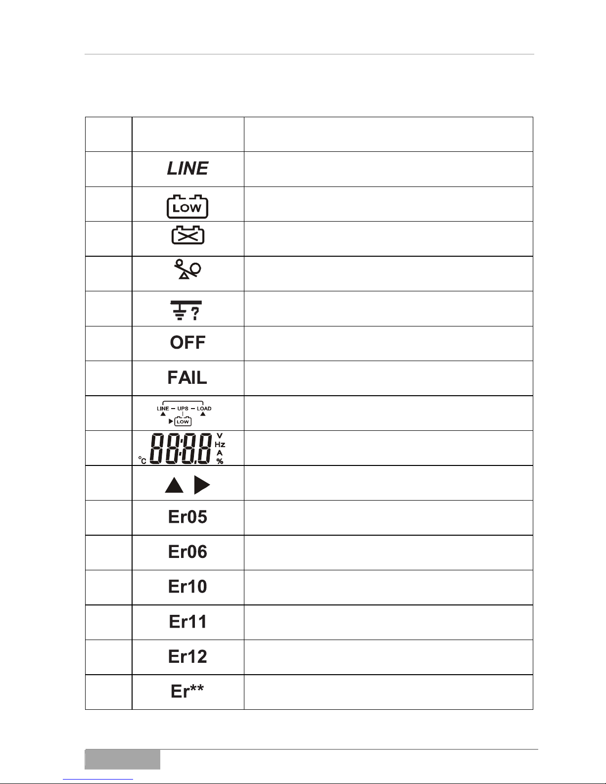
3.1.3 LCD display panel symbols
Item Symbol Description
1 Power supply (utility) or bypass source
2 Battery low
3 Battery problem
4 Output overload
5 Local wire problem
6 UPS shut off
7 Abnormal UPS lock
8 UPS flow
9 4-digit display
10 Indicates which item to be measured
22 Weak or dead battery
23 Output short circuit
24 Inverter overload
25 UPS overheated
26 UPS output overload
27 Other faults
MD Series 28
MD-1000I / MD-2000I / MD-3000I Explanation of USB Function
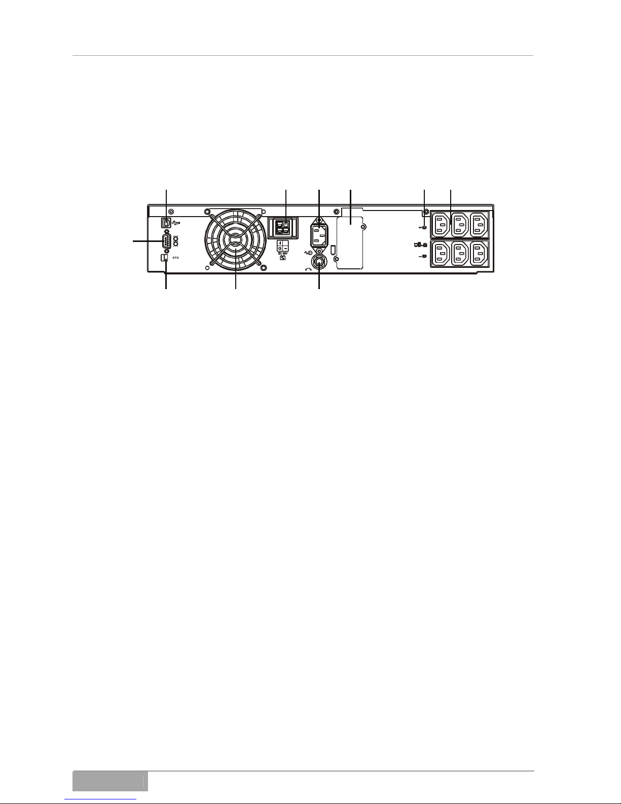
3.2 Rear Panel
123546
789
10
3.2.1 MD-1000I
1 USB port
2 Battery pack connector
3 Power input
4 Communication interface
5 Two programmable outputs
6 UPS output
7 Input circuit breaker
8 Fan
9 Emergency power off (EPO) port
10 RS-232 port
Fig. 3-2 - 3 MD-1000I rear panel
MD Series 29

MD-1000I / MD-2000I / MD-3000I Explanation of USB Function
When the USP output and power input sockets are in connected states,
they are capable of transmitting power.
Even if disconnected, dangerous electrical charges may be present inside the unit that could discharge hazardous high voltage at the connections.
As soon as the unit is connected to a source of power, the charger becomes
active. That means without turning the UPS on, the battery charges.
MD Series 30

MD-1000I / MD-2000I / MD-3000I Explanation of USB Function
12345
666677889
10
3.2.2 MD-2000I
1 USB port
2 Battery pack connector
3 Input circuit breaker
4 Power input
5 Communication interface
6 UPS output (non-programmable)
7 UPS output (programmable)
8 Fan
9 Emergency power off (EPO) port
10 RS-232 port
Fig. 3-2 - 4 MD-2000I rear panel
MD Series 31

MD-1000I / MD-2000I / MD-3000I Explanation of USB Function
When the USP output and power input sockets are in connected states,
they are capable of transmitting power.
Even if disconnected, dangerous electrical charges may be present inside the unit that could discharge hazardous high voltage at the connections.
As soon as the unit is connected to a source of power, the charger becomes
active. That means without turning the UPS on, the battery charges.
MD Series 32

MD-1000I / MD-2000I / MD-3000I Explanation of USB Function
12 2 3455678
999101011
12
3.2.3 MD-3000I
1 USB port
2 Fan
3 Battery pack connector
4 Circuit breaker for two programmable outputs
5 Circuit breaker for two non-programmable outputs
6 Power input circuit breaker
7 Power input
8 Communication interface
9 UPS output (non-programmable)
10 UPS output (programmable)
11 Emergency power off (EPO) port
12 RS-232 port
Fig. 3-2 - 5 MD-3000I rear panel
MD Series 33

MD-1000I / MD-2000I / MD-3000I Explanation of USB Function
When the USP output and power input sockets are in connected states,
they are capable of transmitting power.
Even if disconnected, dangerous electrical charges may be present inside the unit that could discharge hazardous high voltage at the connections.
As soon as the unit is connected to a source of power, the charger becomes
active. That means without turning the UPS on, the battery charges.
MD Series 34

MD-1000I / MD-2000I / MD-3000I Explanation of USB Function
3.2.4 UPS output
IEC 10 A socket for equipment connection
The protective earth conductor must be connected!
Make sure you observe the input voltage requirements that appear on the
identification label and in the technical information provided in this manual.
3.2.5 Emergency power off (EPO) port
The emergency power off port permits the connected equipment to shut down
in emergencies. This function is available for use in the event of connected
equipment emergency.
Make sure to isolate this electrical circuit from hazardous electrical circuits.
Do not connect the EPO to electrical circuits that connect directly to the power
mains.
Make sure power mains lines are heavily insulated.
The EPO switch must have snap-action and at least 24 V DC / 20 mA capacity
and install without connection to another electrical circuit.
To function properly, the EPO signal must remain active for a minimum of 20
ms.
MD Series 35

MD-1000I / MD-2000I / MD-3000I Explanation of USB Function
3.2.6 Relay card (potential-free)
Fig. 3-2 - 6 Relay card (potential-free)
Pin configuration:
1 2 3 4 4 5 6 7 8 9 10
1 UPS in bypass mode (Bypass)
2 Normal power source (normal: closed contact)
3 Normal power source (normal: open contact)
4 Inverter on
5 Battery low
6 Battery bad or abnormal
7 UPS alarm
8 General
9 UPS positive (+) signal
10 UPS negative (-) signal
MD Series 36

MD-1000I / MD-2000I / MD-3000I Explanation of USB Function
The shutdown function activates after +6~+25VDC between PIN 9 and Pin 10
is applied for 5 seconds.
Each relay contact has a load capacity of 40VDC/25mA.
Installation: random insert.
Flexible output for N.C. (normal closed) or N.O. (normal open)
Sets via the repositioning of Jumper Pin1-2 or Pin2-3 from JP1-5.
The shutdown function activates within a minute after the flow of current
ceases when Pin1-2 of both jumpers CN1 and CN6 are connected. The shutdown function activates only from C3 via PIN9-10 when Pin2-3 of both CN1
and CN6 are closed.
3.2.7 SNMP cards (Web card)
Fig. 3-2 - 7 SNMP cards (Web card)
For information about installing SNMP cards, please see the SNMP card manual enclosed with the UPS documents.
3.2.8 USB port
The UPS port allows you to connect the UPS to a PC.
MD Series 37

MD-1000I / MD-2000I / MD-3000I Explanation of USB Function
3.2.9 Fan
Fan cools UPS.
3.2.10 Power input
IEC power plug
MD-1000/2000 - C13/10A
MD-3000 - C19/16A
The unit connects to the power supply by means of the enclosed power cable
with Schuko plug.
The protective earth conductor must be connected!
Make sure you observe the input voltage requirements that appear on the
identification label and in the technical information provided in this manual.
MD Series 38

MD-1000I / MD-2000I / MD-3000I Explanation of USB Function
3.2.11 RS-232 port
PIN 3: RS-232 Rx
PIN2: RS-232Tx
PIN5: Earth/Ground
Fig. 3-2 - 8 RS-232 ports
MD Series 39

MD-1000I / MD-2000I / MD-3000I Explanation of USB Function
3.3 Installation Changes
The UPS features placement versatility to accommodate specific needs:
Vertical standing on feet
Horizontal in 19" rack
Depending on your chosen means of installation, you will need to turn the LCD
display (tower) or mount brackets to the unit (19" rack).
3.3.1 Tower
Fig. 3-3 - 1 Tower configuration
Proceed as described in the following:
Turn the display, so you can read it when the unit is standing.
Install the feet.
MD Series 40

MD-1000I / MD-2000I / MD-3000I Explanation of USB Function
Make sure the floor under the UPS is even and level.
The floor must have sufficient weight-bearing capacity.
For specific weight-bearing requirements, you'll find the UPS weight in
the technical information ( Chapter 11 Technical Information)
Turning the display:
Fig. 3-3 - 2 Turning of display
The display is capable of turning 90°.
MD Series 41

MD-1000I / MD-2000I / MD-3000I Explanation of USB Function
3.3.2 Rack installation
Fig. 3-3 - 3 Rack installation
Proceed as described in the following:
Turn the display, so you can read it when the unit is in the rack.
Mount the brackets to the housing.
Insert the UPS into its compartment in the 19"-rack.
MD Series 42

MD-1000I / MD-2000I / MD-3000I Explanation of USB Function
Fig. 3-3 - 4 Rack brackets
Mount the brackets to both sides of the housing.
MD Series 43

MD-1000I / MD-2000I / MD-3000I Explanation of USB Function
Fig. 3-3 - 5 19"-rack
Insert the UPS into the 19"-rack.
MD Series 44

MD-1000I / MD-2000I / MD-3000I Explanation of USB Function
1 Screws
Fig. 3-3 - 6 Fixing the UPS in the 19"-rack
Use the screws (1) to fasten the UPS to the rack.
Upon completion, you may connect the UPS and put it into operation.
MD Series 45

MD-1000I / MD-2000I / MD-3000I Explanation of USB Function
MD Series 46
3.4 Operational Modes and Voltage Settings
Download the UPS Setting Tool software and open the software, so that you
have the window shown below open.
System configuration settings
1. Selecting power supply voltage: Select the input voltage 230V.
2. Next, select the output voltage from: 200V/208V/220V/230V/240V.
3. UPS mode: Select normal mode /CF50*/CF60*.
4. Output voltage fine tuning: output voltage 0 - ±3%
5. Bypass voltage: low or high
Low High
220V-system 184V~260V 194V~260V

MD-1000I / MD-2000I / MD-3000I Explanation of USB Function
6. Syn-Frequency Window: Select 3Hz/1Hz inverter frequency
range
7. Com. port: Select the PC’s communication port
8. Click Write to confirm the configuration settings. The UPS sounds two audi-
ble tones to indicate you have successfully made the settings.
9. After you have completed the configuration, shut the UPS down to make
sure the system saves all the settings in the EEPROM. To activate the new
setting, restart the UPS.
NOTE: *
CF50/CF60 = Frequency inverter mode 50 to 60Hz or vice versa.
MD Series 47

MD-1000I / MD-2000I / MD-3000I Explanation of USB Function
Programmable output settings
To meet the power needs of less critical equipment, the UPS comes with 2
programmable outputs. You can deactivate these outputs to shut down less
critical equipment while the UPS is running on the battery or to reduce the load
in order to ensure the critical equipment will continue to receive power.
Click Programmable Outlet Scheme to make the following settings:
MD Series 48

MD-1000I / MD-2000I / MD-3000I Explanation of USB Function
MD Series 49
1. "Outlet turn on, after UPS on" allows you to set the time delay. Set the delay
between the time when the UPS turns on and the time when the output
automatically activates. Select "0" if you want the outlet to activate immediately when the UPS powers up.
2. "Outlet turn off, after AC failure" permits you to make setting for power failure events. Select this option to shut the output off automatically within the
predetermined time frame in the event of a power outage, in order to shut
down less critical equipment to allow the more critical equipment more battery time for back-up, etc.
3. "Outlet turn on after AC recovery." Use this option to set the time when the
output will automatically reactivate after regular power has been restored.
4. "Outlet turn off when UPS overload" Select this option to turn off the outlet
automatically when the battery has a specified remaining capacity, which
you specify here. This permits you to shut down less critical equipment in
order to allow the more critical equipment more battery time for back-up,
etc.
5. "Outlet turn off, when UPS overload": This item allows you to specify that
the outlet automatically switches off (bypass mode) during an overload
event, in order to provide more critical equipment with power as described in
the following: Continuously via bypass, or via return to normal operation, if
the shutdown of less critical equipment has successfully remedied the overloaded status.
6. To perform further configurations, you need to click Setting. Consider new
settings successfully completed when the UPS emits two audio signal
tones. After you have completed the configuration, shut the UPS down to
make sure the system saves all the settings in the EEPROM. To activate
the new setting, restart the UPS.
7. Manual Control Switch: Click On or Off to activate or deactivate programmable outputs and overwrite all previous settings.

MD-1000I / MD-2000I / MD-3000I Storage and Unpacking
MD Series 50
4. Storage and Unpacking
4.1 UPS Storage
If you don't put the UPS into operation immediately, you need to follow the instructions below:
Always store the unit and any accessories in their original packaging.
Suggested ambient storage temperature is 0 to +40° C.
Protect this product and the packaging against moisture.
If you are storing the UPS longer than 4 months, it is necessary, when you
reach 4 months, to connect the UPS and the external battery string (optional)
to a power source for about 8 hours to avoid extensively expending the charge.
4.2 Unpacking the UPS
Remove the box in which the product came and the packing materials.
Always keep the UPS in a horizontal position.
Compare the packing list to the package contents to determine if anything
is missing. Notify the vendor immediately if something is missing or if you
have received something you did not order.
In addition, inspect the contents for any damage. Report any shipping or
handling damages immediately:
– Save the boxes and packing materials
completely for potential claims.
– Notify the manufacturer immediately and/or your vendor.
– Notify the shipping company immediately.

MD-1000I / MD-2000I / MD-3000I Storage and Unpacking
MD Series 51

MD-1000I / MD-2000I / MD-3000I System Function
MD Series 52
5. System Function
The UPS operates continuously employing double conversion online topology.
It processes the power provided by the power source, providing uninterrupted,
clean, single-phase power for the critical equipment.
Besides furnishing the connected equipment with power, the UPS charges the
internal battery, keeping it charged to its capacity. In the event of a power failure or disturbance, the UPS continues to provide uninterrupted, clean power to
the UPS output, supplied by the battery.
5.1 UPS Schematic Diagram
Fig. 5-1 - 1 Block diagram
The block diagram depicts the individual UPS modules and displays their interaction roughly.

MD-1000I / MD-2000I / MD-3000I System Function
Important
UPS components are:
– AC to DC power converter (rectifier)
– AC to DC high frequency power inverter
– Smart battery charger
– String consisting of durable maintenance-free batteries
– DC to DC push-pull inverter
– Static bypass lead
– Input and output EMI filter
The following table contains a summary of the UPS' power input and battery
workings.
Power Supply
(utility) Status
UPS Operating Mode LED Display
Normal power Power converter (rectifier)
converts AC to DC, battery
charges, inverter converts DC
to AC, providing clean stable
power
, ,
LEDs illuminate
Power supply
(utility) abnormal
(over or under
voltage) / unavailable
Power converter and charger
cease operating, Battery
discharges via DC~DC protective circuit and delivers
power to the inverter. Load
continues to receive power
from the inverter. Audible
alarm sounds, the UPS is
operating in battery mode.
LED off,
LED illuminates
Power supply
(utility) abnormal /
unavailable, battery almost discharged
Power converter and charger
cease operating, Battery
discharges via DC~DC protective circuit and delivers
power to the inverter. Audible
alarm sounds with fast and
short intervals, indicating
battery charge is becoming
critical and the inverter will
soon cease to deliver power.
LED off, &
LED illuminates
MD Series 53

MD-1000I / MD-2000I / MD-3000I System Function
MD Series 54
5.2 UPS Operating Mode - Normal
Normal UPS operation is as shown below:
Fig. 5-2 - 1 During normal power supply
The inverter converts DC into clean, stable AC. Output LEDs 2 and 4 light.

MD-1000I / MD-2000I / MD-3000I System Function
Abnormal UPS operation is as shown below:
Fig. 5-2 - 2 During abnormal power supply
If the power supply is abnormal, the UPS battery automatically transmits power
to the inverter, shuts off the charger and the AC-DC power converter (rectifier).
The inverter converts the DC to AC, in order to supply the connected equipment with uninterrupted energy.
As soon as the power coming from the supply returns to normal, the UPS
opens the AC-DC power converter (rectifier), shuts off the DC-DC converter
and turns the charger on.
During a power outage, the UPS operates as shown in ( Fig. 5-2 - 1 During
normal power supply). When battery level becomes too low, the audible alarm
signal begins and continues until the battery shuts down. The UPS automatically stops battery-supplied power when battery capacity reaches a certain limit
in order to prevent complete discharging. The UPS starts automatically when
the mains is again available.
MD Series 55

MD-1000I / MD-2000I / MD-3000I System Function
5.3 Overload
UPS operation when overloaded is as shown below:
Fig. 5-3 - 1 Overloaded situation
Generally, modern electronics and IT equipment produce inrush current when
they start. The magnitude of the inrush current varies depending on the equipment. Sometimes the current can be 6 times as high as measured capacity,
while other devices generate inrush that is insignificant.
The UPS has an overload protection that protects it from inrush current. If the
overload exceeds 105~120% of its capacity, it automatically switches to bypass
within 30 seconds, in order to protect the inverter. As soon as the overload
drops below <105%, the UPS returns to the inverter mode. If the UPS load exceeds 150%, the inverter automatically shuts down.
MD Series 56

MD-1000I / MD-2000I / MD-3000I System Function
5.4 Inverter
Fig. 5-4 - 1 Inverter malfunction
Output short circuit
If a short circuit occurs in the output while the connected equipment is receiving current from the inverter, the UPS automatically shuts down the inverter
and ceases supplying the equipment with power. LEDs indicate malfunction
and the audible alarm goes off. Once the short circuit has been remedied, the
UPS does not automatically start, but requires manual action to restart.
MD Series 57

MD-1000I / MD-2000I / MD-3000I System Function
MD Series 58
5.5 Inverter - Excessive Internal Temperature
Raised temperatures in the UPS automatically set off the bypass mode. The
UPS switches back over to normal operation, once the temperature has returned to normal. If excessive termperatures occur while the energy supply is
abnormal, the audible alarm sounds and the LEDs indicate malfunction. The
UPS ceases to supply the equipment with power.
If a power outage exceeds the duration of the UPS' power supply, the UPS will
shut down to protect the battery from deeply discharging. When the mains
comes back on, the UPS kicks back on, energises connected equipment and
controls the recharging of the battery/battery string.
The UPS has many outstanding features:
– Absolutely no interruptions or change in signal if a primary power source
outage occurs
– Pure sine wave output. The quality of the output voltage is significantly bet-
ter than that of the mains input.
– Processor-controlled bypass
– Input Power Factor Correction (> 0.95).
– LCD status and operating display
– Excellent Power Factor of 0.8
– Powerful and extensive communication interfaces
– RS-232 is standard
– USB is standard
– Programmable switch contacts are standard.
– NOT-HALT EPO contact is standard.

MD-1000I / MD-2000I / MD-3000I System Function
MD Series 59

MD-1000I / MD-2000I / MD-3000I UPS Installation and Hook-Up
6. UPS Installation and Hook-Up
All instructions in technical information pertaining to the operating environment
and operating conditions are mandatory and necessary to the proper function
and operation of the UPS.
For the installation of the UPS in a tower or rack configuration, the following instructions apply:
– Avoid extreme temperatures and relative humidity.
– Follow the instructions provided for the horizontal rack installation.
– Make sure the unit has adequate ventilation with sufficient unhindered air-
flow.
– Be careful when integrating the UPS in other systems, e.g. machines or
switch gear cabinets. Make sure the UPS' environment remains within the
specified temperature requirements. If heat is prone to accumulate in the
environment, you must act to provide suitable ventilation.
– Only a base plate is suitable to anchor the unit.
6.1 UPS Connection
These models come equipped with plug-and-socket connectors.
The UPS system contains components with high voltage and amperage.
Improper use or handling can lead to electrical shock, injuries with death
and/or property damage.
The protective earth conductor must be connected! If it is not grounded,
the connected equipment is also not earthed.
If operating with a generator, make sure not to reverse the connection's
polarity.
If the UPS is in an emergency stop (NOT-HALT) cycle, the UPS output will still
carry power. The connected equipment receives electricity for the duration
while the UPS' electricity backup function is operating.
MD Series 60

MD-1000I / MD-2000I / MD-3000I UPS Installation and Hook-Up
1 Power mains
2 16 A
3 1.5 mm
2
4 Load 1
5 Load 2
Fig. 6-1 - 1 UPS and connected equipment connections
MD Series 61

MD-1000I / MD-2000I / MD-3000I UPS Installation and Hook-Up
MD Series 62
6.2 UPS Communication Interfaces
The UPS has convenient communication features for data transfer.
Only a single communication port can be active. The USB port has priority over
the RS-232 port.
If a communication cable is connected, the software can exchange data with
the UPS. The software gathers information from the UPS about the power supply status. In the event of a power emergency, the software backs up the data
and shuts down the equipment properly.
6.2.1 RS-232 port
Use only those cables specified in the Chapter "Accessories" (1 : 1).
Pin Configuration
2 RS-232 Tx Receiving line Rx or shut down SD
3 RS-232 RX Transmitting line Tx
5 Ground GND
The communication interface is completely isolated via galvanic means.
6.2.2 SNMP communication interface
The UPS can be ordered or fit with a SNMP interface.

MD-1000I / MD-2000I / MD-3000I UPS Installation and Hook-Up
6.3 Equipment Connection Sequence
Connect the UPS to source of power, but make sure the power source and
the UPS are both reliably shut down.
Before connecting equipment to the UPS outlet, you must perform the ini-
tial configuration.
Connect the equipment to the UPS, making sure that all the equipment is
turned off.
6.3.1 EPO connection configuration
Function Connection wire gauge Suggested gauge
EPO 4 - 0.32 mm2
(12 - 22 AWG )
0.82 mm2 (18 AWG)
MD Series 63
Leave the EPO p
lug installed on the UPS' EPO port, even if you don't plan to
use the EPO function.
Fig. 6-3 -
1 EPO plug
Follow
the instructions for the EPO port as stated in Chapter 3.2.5 EPO port.

MD-1000I / MD-2000I / MD-3000I System Operation and Display
MD Series 64
7. System Operation and Display
7.1 UPS Modes and Display Messages
s
Operating this system involves different operational modes and control communications.
7.2 USP User Instruction
The user of this UPS system must invariably follow and adhere to the instructions and guidelines provided in this manual at all times. The user
may perform only those actions described in the following and the user
must perform them with great care:
Controls: energizing the UPS and switching it on and off
Reading the display and interpreting audible warnings
Activating the test operation
Use the communication interface, but if the UPS installation includes a
permanent connection, the connection to a PC or other systems should be
already present.
Thanks to comprehensive protective and safety functions that the UPS
performs in conjunction with the connected equipment, the UPS's operation is completely automatic. The user need only energize and turn the
unit on and off. In addition, communication interfaces allow the transfer
of data via SNMP adapter, which, however, is not necessary for the regular operation of the system.

MD-1000I / MD-2000I / MD-3000I System Operation and Display
7.2.1 Turning on the UPS
Connect the power cable to the UPS.
The UPS starts.
Fig. 7-2 - 1 UPS power cable connected
Hold the button USV Ein down ( Fig. 3-1 - 2, Item 12) until the unit emits an
audible alarm. The UPS will perform a self test during initialisation.
Fig. 7-2 - 2 Self test
If the initialisation was successful, the input voltage will appear on the LCD display.
MD Series 65

MD-1000I / MD-2000I / MD-3000I System Operation and Display
Fig. 7-2 - 3 Main display
If the system fails the self test, it will indicate failure on the LCD display.
Figure. 7-2 - 4 Failure
7.2.2 Turning off the UPS
Hold the button USV Aus down ( Fig. 3-1 - 2, Item 11) until the unit emits an
audible alarm. The UPS shuts down.
Fig. 7-2 - 5 UPS is off
Please remember that the UPS shuts down only the outputs. To completely
shut down the UPS, you must disconnect the power cable. Bear in mind that
the connected equipment will no longer have power.
MD Series 66

MD-1000I / MD-2000I / MD-3000I System Operation and Display
7.2.3 Menu
7.2.4 Readings
With the Scroll Down ( Fig. 3-1 - 2, Item 9) Scroll Up ( Fig. 3-1 - 2, Item 8)
keys, you can view the various values monitored by the system.
Menu structure:
Fig. 7-3 - 1 Input voltage
Fig. 7-3 - 2 Input frequency
Fig. 7-3 - 3 Output voltage
MD Series 67

MD-1000I / MD-2000I / MD-3000I System Operation and Display
Fig. 7-3 - 4 Output frequency
Fig. 7-3 - 5 Capacity in use
Fig. 7-3 - 6 Battery charging voltage
Fig. 7-3 - 7 Temperature inside UPS
MD Series 68

MD-1000I / MD-2000I / MD-3000I System Operation and Display
7.2.5 Menu functions
Press Other Functions ( Fig. 3-1 - 2, Item 10) to view the menu.
Menu structure:
Fig. 7-3 -
8 Audible signal ON / OFF
Fig. 7-3 - 9 Run self test
Fig 7-3 - 10 Bypass voltage
Fig. 7-3 - 11 Bypass frequency
MD Series 69

MD-1000I / MD-2000I / MD-3000I System Operation and Display
Fig. 7-3 - 12 Inverter output voltage
Fig. 7-3 - 13 UPS operating mode: Online, 50Hz or 60Hz at output
Fig. 7-3 - 14 Inverter output settings:
+1% -1%, +2% -2%, +3% -3%
MD Series 70

MD-1000I / MD-2000I / MD-3000I System Operation and Display
Consult your dealer or specialist before you change the settings in this
menu. Wrong settings may cause the system to malfunction or even
damage the UPS irreparably.
You'll find a description of the parameters in the following table.
Parameters Possible Settings Standard
Value
MD Series 71

MD-1000I / MD-2000I / MD-3000I System Operation and Display
1
1
7.3 Replacing Batteries
Risk of electrical shock
Battery replacement must be performed by QUALIFIED SERVICE PERSONNEL ONLY!
Even when the UPS is turned off, the batteries and UPS components
carry hazardous electrical charges.
To replace batteries, please proceed as described in the following:
1 Covers
Fig. 7-4 - 1 Removing covers
Remove the covers (1) on the UPS' front panel.
MD Series 72

MD-1000I / MD-2000I / MD-3000I System Operation and Display
1
1
1 Screws
Fig. 7-4 - 2 Screws
Remove both screws (1)
MD Series 73

MD-1000I / MD-2000I / MD-3000I System Operation and Display
1
1 Front panel cover
Fig. 7-4 - 3 Front panel cover
Slide the front panel cover (1) to the left out of the housing.
MD Series 74

MD-1000I / MD-2000I / MD-3000I System Operation and Display
1
Model MD-1000I
1 Connector
Fig. 7-4 - 4 MD-1000I
Unplug the connector (1)
Pull the battery out of the housing.
MD Series 75

MD-1000I / MD-2000I / MD-3000I System Operation and Display
1
1
Model MD-2000I and MD-3000I
1 Connector
Fig. 7-4 - 5 MD-2000I and MD-3000I
Unplug the connector (1)
Pull both batteries out of the housing.
MD Series 76

MD-1000I / MD-2000I / MD-3000I Trouble Shooting Guide
8. Trouble Shooting Guide
Only authorised qualified service personnel are to perform repairs or corrective actions to remedy UPS system malfunctions.
Situation Description Audible Signal Description
UPS malfunction, serious
problem
Long continuous audible signal
UPS malfunction, power still
provided via inverter or bypass
Single continuous audible signal with ~2second interval
Battery mode Single short audible signal with ~1-
second interval
Battery low Very fast and short continuous signal
Verify/RS-232 connection 2 short, fast audible signal tones
Service mode ok 1 faster and shorter audible signal tone
UPS starts first with self-test 2 continuous fast and short audible
signal tones repeating in ~2-second
intervals.
MD Series 77

MD-1000I / MD-2000I / MD-3000I Trouble Shooting Guide
Situation Malfunction Message
/
Meaning
Solution
UPS failure LED
Read the failure code
indicated by LEDs.
1. Er05 battery weak
or defective
1. Check if the battery is properly
connected. Check battery voltage to
determine if the batteries are
charged and free of defect. If necessary, charge the batteries 8 hours.
2. Er12 Overload
2. Disconnect the uncritical equipment from the UPS outputs until the
overload has subsided. Check to
see if insufficient cable insulation
has caused a short circuit. If necessary, replace the cable(s).
3. Er11 (UPS Excessive temperature)
3. Clean plugged up vents. Check to
make sure the fan is working properly. If necessary, ask your local
dealer to replace the fan.
4. Local cable or
earthing problem
4. Check to see if the "L" and "N"
phases of the AC power lead are
wrongly wired or if the earth neutral
wire voltage exceeds the limit.
5. Er14 (Fan defective)
5. Check to see if the fan is operating properly. Do not attempt to
replace the fan. Contact your local
distributor.
6. Other faults codes 6. Contact your local dealer for
assistance.
MD Series 78

MD-1000I / MD-2000I / MD-3000I Trouble Shooting Guide
UPS doesn't p
rovide
interval time or time is
shorter than expected.
If the back-up time is still shorter than
required after charging for 8 hours,
please contact your local dealer for
technical assistance.
UPS appears to be normal, but there is absence
of output voltage.
Check to see if all
power cables are properly connected.
If the problem persists, contact your
local dealer for technical assistance.
Unusual sounds or smells Shut down the entire system immedi-
ately. Turn off the power supply and
contact your technical customer service.
UPS cannot run battery Check the battery connections. If the
batteries are weak, let them charge for
a while. If the problem persists after
you have charged the batteries, replace them. If the problem still persists, contact your local dealer for
technical assistance.
MD Series 79

MD-1000I / MD-2000I / MD-3000I Trouble Shooting Guide
MD Series 80
Malfunction code:
Code Meaning
Er05 Battery weak or defective
Er06 Output short circuit
Er07 EPO mode
Er11 UPS under excessive temperature
Er12 Inverter overload
Er14 Fan defective
Er18 EEPROM data error
Er24 Power supply low (<85/170V) and battery not
connected
Er28 Bypass overload
Er31 EEPROM data doesn't match. Settings of
control and driver boards don't match.
If you don't find the failure in the table, please contact our service department.
You'll need to provide the following information when you talk to them.
1 Model number, serial number
2 Date on which the problem first occurred
3 Detailed description of the problem

MD-1000I / MD-2000I / MD-3000I Software
9. Software
Connect the RS-232 or USB cable connector to the UPS communication
port.
Connect the RS-232 or USB cable socket to a suitable RS-232/USB com-
puter port.
A suitable software package can monitor and process UPS settings and operational status via communication port.
Software is available from the manufacturer, distributor or the provided hotline,
where you'll receive useful information for selecting the most suitable software
based on your needs and UPS.
Visit our Web site for further information:
http://www.edelstrom-usv-systeme.de
The follo
wing basic functions are supported by any software package:
– Identification and display of UPS power source status
– Display of UPS output status
– Identification and display of the battery string charge status
– Shutting down open applications if power fails
– Shutting down operating system
– Generating log files
– General monitoring of UPS data and conditions (diagnostics)
You'll find more detailed information about the individual software packages,
such as installation, operation and scope in the software manual.
In Chapte
r "Included Components and Accessories," you'll find a suitable,
tested software package.
MD Series 81

MD-1000I / MD-2000I / MD-3000I Maintenance and Service
MD Series 82
10. Maintenance and Service
With just a little maintenance, you will have the uninterrupted use of your UPS
system for a long time.
Please note that the dependability of the UPS is very much affected by its environment. Temperature and relative humidity must be kept at reasonable levels.
In addition, the area around the UPS should be kept as clean and dust-free as
possible.
At the optimum ambient temperature of 22° C, the typical battery life span is
approx. 4 years. Special-purpose, high-performance batteries will significantly
increase longevity, reaching around 8-10 years.
Regularly, (every 6-12 months), you should check to make sure the system
back-up capacity suffices for the intended purpose. If this is not the case, it is
necessary to replace the batteries.
10.1 Determining the Back-up Capacity
Before you begin this procedure, make sure all open documents and data
are backed up/saved. Also, be sure to inform all personnel who may be
affected.
There are two methods of determining the back-up capacity.
Method a)
is suitable for measuring the actual duration of time until the connected
equipment loses power.
Method b)
Permits determination of the remaining power capacity after a run using a
specified back-up time. Connected equipment usually does not lose
power in this instance.
To use one of these methods, it is necessary for you to simulate a situation that forces the UPS into battery back-up operation (e.g. turning off
building circuit breaker). Do not disconnect the power cable, as this will
break the earthing (neutral) connection. Once you have completed the
test, switch the circuit breaker back on and start the UPS as usual with
the ON button.

MD-1000I / MD-2000I / MD-3000I Maintenance and Service
Remember that after the test the batteries are low. The UPS system will need
to run several hours (min. 5 hr) on the mains before it reaches about 80% capacity.
If you fail to perform a battery back-up test regularly, we suggest, for the sake
of prevention, replacing the batteries every two years in order to safeguard the
availability of your system against failure caused by battery degradation.
MD Series 83

MD-1000I / MD-2000I / MD-3000I Maintenance and Service
MD Series 84
10.2 Service Log
Always record all maintenance and service work performed on the UPS system
in the Service Log.
Date Work Performed Performed By

MD-1000I / MD-2000I / MD-3000I Maintenance and Service
MD Series 85
10.3 Service Hotline
If contrary to expectations, you experience problems with the UPS or if you require assistance with safety-related information, please use our Service Hotline, either phone or fax:
Phone: 0049 / (0) 741 – 9292-0
Fax: 0049 / (0) 741 – 9292-33
If for whatever reason, telephone service is unavailable to you, you may use
the following e-mail:
E-mail: kundenservice@multimatic-usv.de
10.4 Maintenance and Service Contracts
multimatic Vertriebs GmbH provides maintenance and service that guarantee
the best possible dependability and availability of your UPS system.

MD-1000I / MD-2000I / MD-3000I Technical Information
11. Technical Information
Model MD-1000I MD-2000I MD-3000I
Output
Output in VA 1000 VA 2000 VA 3000 VA
Output in W 800 W 1600 W 2400 W
Power factor 0.8
Topology Online double-conversion
Placement Tower or 19"-rack
Safety CE
Input
Voltage range 120/140/160 - 288 VAC
Basis charge percent (0~33/33~66/66~100%)
Under voltage 120/140/160Vac
Under voltage start 170Vac
Over voltage 288 VAC
Voltage
Over voltage start 278 VAC
Frequency 50/60 Hz auto-select, ± 5Hz
Phases Single-phase with earth
PF > 0.99 at full measured linear load
Typical transfer time 0 ms.
Leakage current ≤ 3.5 mA
Surge protection 300 Joule
Output
Voltage 230V, adjustable to 200/208/220/230/240
Voltage setting ≤± 1% until weak battery warning
Frequency (synchronised range)
3Hz or 1Hz (setting via software)
Frequency (battery
mode)
±0.1% (0.05~0.06Hz) if not synchronised with
line
Crest factor 3:1
Total harmonic distortion
3% THD (linear l ad) o
7% THD (non-linear load)
Dynamic response
(ms)
<=60ms/5%
Output (INV.
mode)
Wave form type True sine wave
Efficiency AC mode (full load) 85% 85% 88%
Battery mode (full
load)
83% 83% 85%
Battery system
Type 12V/7.2Ah 12V/7.2Ah 12V/9Ah
Number of batteries 3 6 6
Back-up time (full load) >7min. >7min. >5min.
Recharge time 4 hours to 90%
Charge current (max.) 1.1A 2.16A 2.7A
Charge voltage VDC (DC high) 41.0Vdc±0.5 82.0Vdc±0.5 82.0Vdc±0.5V
MD Series 86

MD-1000I / MD-2000I / MD-3000I Technical Information
V V
Hot swappable battery Yes
Internal battery Yes
DC leakage current ≤ 30uA (±10uA) with AC not in use and the unit
off
Battery type Sealed, maintenance-free, lead battery
Transfer time
AC to DC None
Inverter to bypass 2.5ms (typically) None
DC start Yes
Self diagnostics Switch located on panel or software
Front panel
LED Load level/Battery level/ Battery mode/ Normal
mode/Bypass mode/ Self test/ Weak/Bad battery/Local cable failure/ Failure/ Overload/
Programmable output 1/Programmable output 2
Keypads ON key/ OFF key/ (Test/Alarm reset key)
Protection
(AC mode)
<105% unlimited
>106%~120% for 30 seconds, then bypass
mode
>121%~150% for 10 seconds, then bypass
>150% immediate transfer to bypass
Continuous audible signal (tone)
(Battery mode)
<105% unlimited
>106%~120% for 30 seconds, then shut down
>121%~150% for 10 seconds, then shut down
>150% for immediate shut down
Continuous audible signal (tone)
Overload
(Bypass mode)
<105% unlimited
>106%~120% for 250 seconds, then shut
down
>121%~130% for 125 seconds, then shut
down
>131%~135% for 50 seconds, then shut down
>136%~145% for 20 seconds, then shut down
>146%~148% for 5 seconds, then shut down
>149%~157% for 2 seconds, then shut down
>158%~176% for 1 seconds, then shut down
>177%~187% for 0.32 seconds, then shut
down
>188% for 0.16 seconds, then shut down
Continuous audible signal (tone)
Short circuit Bypass mode: input circuit breaker
Normal mode: output circuit breaker
MD Series 87

MD-1000I / MD-2000I / MD-3000I Technical Information
Battery mode: output circuit breaker
EPO UPS shuts down immediately
Normal mode Transfer to bypass mode Excessive
temperature
Battery mode UPS shuts down immediately
Audible alarm
Battery mode Audible signal every 1.5 seconds once
Weak battery Audible signal every 0.2 seconds once
Overload Audible signal every 3 seconds once
Failure Continuous audible signal
(or every 3 seconds once)
Physical
Dimensions (HxWxD in mm) 88(2U)x440x
405
88(2U)x440x
650
88(2U)x440x
650
Weight 15.7kg 29.4kg 29.7kg
Input connector 10A, IEC
320-C14
10A, IEC 320-
C14
16A, IEC
320-C20
Output connector (6) 10A,IEC 320-C13 (4) 10A,IEC
320-C13
(1) 16A,IEC
320-C19
Environmental
Operating temperature 0-40
Noise level <50dBA
Relative humidity 0 to 90% (without condensation)
Interfaces
Type 1 *USB port and 1*RS-232 port
SNMP (optional) Energy management by SNMP manager and
Web browser
Operating systems Windows 95/98/NT/2000/XP Novell NetWare,
Linux, etc.
Standards and certification
Safety IEC/EN 62040-1-1,IEC 60950-1
Performance IEC/EN 62040-3
EMC IEC/EN62040-2 Class A, FCC Part 15
Safety CE,UL, cUL, FCC
MD Series 88

MD-1000I / MD-2000I / MD-3000I Technical Information
MD Series 89
11.1 Included Components and Accessories
In the following, you will find a list of components that multimatic Vertriebs
GmbH has carefully selected, specified and tested for use in this UPS. Please
check to make sure that nothing is missing.
11.1.1 Components
Qt
y.
Name Function / Graphic Article No. In-
cluded
1 UPS electronics,
incl. battery
MD-1000I
MD-2000I
MD-3000I
X
1 User Manual Printed in German X
Software package
multimatic Management Software
CD-ROM Power supply shutdown and
diagnostics software
1 License Windows/Novell
1 License UNIX, LINUX, MAC
multimatic Management Software
X
LAN/RS-232-
connector
Interface cable X
USB cable X
Connecting lead
(IEC 10 A, straight)
X
Output cable
MD-1000I
MD-2000I
(IEC 10 A, straight)
X
Output cable X

MD-1000I / MD-2000I / MD-3000I Technical Information
MD-3000I
(IEC 16 A, straight)
2 Brackets Brackets for 19"-rack X
2 Feet Feet for tower variant X
MD Series 90

MD-1000I / MD-2000I / MD-3000I Technical Information
MD Series 91
11.1.2 Communication ports (optional accessories)
Name Article Number
Relay card 222302000434
SNMP card AR1041, AR1042
11.2 Wear Parts
The components listed below are parts that need replacement because of wear
caused by regular operation of the UPS. These parts are not covered by warranty.
Wear Parts Function Article Number
XXXX XX XX **
Battery 12 V xx Ah
Energy storage (electricity)
Subject to specific
model and UPS configuration. See accessories or consult multimatic Vertriebs
GmbH.
** For battery replacement, see current battery part number or
consult multimatic Vertriebs GmbH.

12. Declaration of Conformity
MD Series 92

MD Series 93

MD Series 94
 Loading...