

Page 1

IPS
Internet
Power Stone
Instruction and Programming
Manual
Multi-Link, Inc.
225 Industry Parkway
Nicholasville, KY 40356
Sales and Technical Support
800-535-4651
www.multi-link.net
The IPS is a device designed to manually and/or
remotely control availability of power to a device
connected to its output. The IPS can be sourced
with either 110/120 or 220/240 volts. The IPS is
fused at 6.3A. Alarger SLO-BLO fuse, up to 10A,
may be used for heavier loads on 110/120 volts
ONLY. DO NOTUSE FUSE LARGER THAN 6.3A
ON 220/240 VOLTS.
LEDs (Operational)
AC IN On = Power available on the IN connector
AC Out On = Power available on the OUT connector
STATUS
Green = Standby
Red = Armed
Red Flash Fast = Auto Re-Arm
Red Flash Slow = Power Reset
Flash .5 Second = Command received from the RS-
232 port (Heart Beat)
Flash Rapid = Ring signal
Red/Green Flash = Standby ring reset
Operating Modes and Instructions for
use of the IPS:
1. Manual Control:
For manual control you only need the IPS device,
an IN AC Adapter Cable, an OUT AC Adapter
Cable, and the device you want to control. The
specifications for the cables, depending on where
they are going to be used are the following:
IN AC Adapter Cables:
North America, 110-115V, NEMA5-15
Receptacle to IEC C13
(Europe 6 feet two prong)
OUT AC Adaptor Cables:
PC extension, IEC 320-C13 to IEC 320-C14
or Cable ICE 320-C13 to NEMA 5-15
Connect cables from the wall power outlet to the
IN connector on the IPS, and from the OUT connector on the IPS to the device you want to control. Simply push the ON/OFF Reset button on the
front of the IPS to reverse the current power state
of the output. By pushing the RESET button for 3
seconds, you will change the “ring timing’
between the slow North American ring and the
quick International ring.The LED on the front of
the IPS will be red(N.A.) or green (International).
2
2. Telco Ring Control
You can recycle power via the telephone line.
Connect the phone line to the port labeled
"TELCO" on the front of the IPS. If con
trolling a computer, connect another phone cable
(RJ-11) to the port labeled "MODEM" on the
IPS, and from there connect the other
end of that cable to the Modem on the computer.
Call into the IPS. If a computer or other
auto-answer device is connected to the IPS
through the Modem jack, the IPS will
recycle power to the connected device(s) if no
device answers before the ring count trigger
of the IPS (Default = 6 rings) is reached.
3. Direct Serial Port Control
When connected to a serial port of a PC or
Controller, the IPS can accept Setup and Control
commands directly from the PC/Controller. It also
returns the unit's status to the serial port. You need
to connect the PC/Controller to the
IPS unit through the RS-232 port. Also need to connect the power cables as described on
previous sections in this manual. (Cont’d)
3
(Cont’d)
Now you need to configure your serial port if
using direct PC control. To do that, one easy
way would be to go on your computer to
Programs/ Accessories/ Communications/ Hyper
Terminal. Once there, enter the following data:
Connect using: COM(x) port (for serial port)
Bits per second: 300
Data bits: 8
Parity: None
Stop bits: 2
When you close this connection, be sure to Save
this connection configuration for future use.
Once you do this, your serial port is set to start
communicating with the IPS. When you want to
communicate to the IPS, you need to open this
connection in your computer. To do that, go
again to Hyper Terminal and open the file name
you gave to the connection when you created
and saved it.
4
The following are the Setup and Control commands for the IPS:
*FRT Factory Reset
*PRy Change recycle time to (10x y sec)
*PRO Change recycle time to 5sec.
*PON Power ON (LED = ON)
*POF Power OFF (LED = OFF)
*PRC Recycle AC power
*PUx Power Up State of IPS
*ARM Arms the IPS (LED = Red)
*SRx Auto Re-Arm timeout (x-min)
*RCx Ring count trigger (x-rings)
*RTx Ring Timing Control
*RVx Reverse Sense of Command Port
*STB Standby mode (LED = Green)
*TNx Tandem Operation Enable
*D.5 0.5 min delay- Code 1
*D1. 1 min delay Code 2
*D2. 2 min delay Code 3
*D4.3 4 min delay Code 4
*D8. 8 min delay Code 5
*D16 16 min delay Code 6
*D32 32 min delay Code 7
*?PS IPS Returns the system status in follow
ing format: x.y1100600000$
To interpret the response string returned by *?PS command and the IPS, use the following chart to define each
character's meaning:
5
Character Description
x.y Software revision x.y
1 or 0 Current State of Relay, 0=Off and 1 = On
1 or 0 The initial power up state of the IPS,
0 = Off and 1 = On (default = 1), *PUx
1 or 0 Ring Timing Control *RTx (default = 0)
- See below
1 or 0 Tandem Operation Enable *TNx (default = 0)
- See below
0 to 9 Number of Rings to reboot (default = 6) *RCx
0 to 7 Current Delay Code *Dxx (default = 0), Heart
Beat Timeout
0 to 9 Current Reset Duration (default = 0 = 5secs
all others seconds = n x 10 secs) *PRy
0 to 9 Secondary Reboot Time (in minutes) (default
= 0) *SRx, Auto Rearm
0 or 1 Reverse sense of Command Port (0 = Normal
1 = Reverse (Default = 0) *RVx - See below.
0 or 1 Date Rate, 0 = 300, 1 = 600 BPS (default = 0)
- See below
$ End of response indicator
The value of character in the string reflect the settings
and status of the IPS.
R
Tx note: Ring Timing control allows setup for "North
American" (1) or "Short/International" (0 = Default) rings.
The default for the "Short/International" rings is used as it
has been found to work for "North American" standard
rings.
R
Vx note: Reverse Control actually reverses the com-
mand received through the RJ jack (Analog Port) from
one of the Reboot Controllers. This allows putting two
IPSs on one line and having them work in opposite
modes from each other. 6
Default is 0 = Normal, 1 = Reversed.
TNx note:
Tandem Operation is for setting the IPS
up in an Alternating (Tandem) installation. In this arrangement the Alternating IPSs work in pairs, communicating
with each other so that one IPS will always be on. Default
is 0 = Normal, 1 = Tandem.
The IPS also keeps the PC updated as to its operating status. These event codes are transmitted as they occur. The
codes are:
P Power up with relay ON
p Power up with relay OFF
M Push button control to ON
m Push button control OFF
T Reset due to Auto Re-Arm
R Reset via ARM time out
r Reset via Ring Count
S Reset via Command port
C Command port power change to ON
c Command port power change to OFF
54321 Reset Ring Count.
Programming Notes:
* The IPS will return a "$" to acknowledge a good command and a "!" as a NAK to a bad command.
* There is a three second timeout for each character and
all data is echoed back to the source (serial port).
* There are times when the IPS cannot receive/echo data
i.e., during a RESET, so the source must be able to retransmit the data and wait until a time exceeded by the
*PRx time.
* The data rate can be increased to 600 bps with a *DR1
command (*DR0 = 300, Default). 7
Basic Reboot
Operation
Incoming
Call
(POTS line)
ON/OFF
RESET
125V, 10A SB for
110 / 120V
250V, 6.3A SB
for220/240v
S
T
A
T
U
S
TELCO MODEM RS-232
Multi-Link, Inc. 1-800-535-4651
PSTN
AC
IN
Controlled
Device
Optional
Heartbeat
reset via
RS-232
AC
OUT
Page 2
4. Automatic Heartbeat Control
The IPS has an RS-232 serial port interface to the PC
or other target device. It will automatically recycle the
AC power if that target hardware or any linked application hangs. For this option, you need a "Heart Beat"
software that sells separately. Please contact our
Sales Department for more information on this
"Windows" based software.
This method will automatically recycle the AC power
on the OUT connector of the IPS. Power is restored
after a customizable recycle time (Default is 5 seconds), if the hardware or a linked application hangs for
a configure-able period of time (no heartbeat is detected on the serial port).
Connect the RS-232 cable to the selected Com Port.
Use a DB-25 to DB-9 adapter cable, if required, and
load the software for the Heartbeat. Remember, a
Windows system is required.
Start "Heart Beat Rebooter" from the program menu. It
will install in the System Tray of the Task Bar. The configuration window will appear the first time it is run. You
will be asked several questions, which are explained in
the "Help" file.
The Heart Beat icon in the system's tray exhibits the
current state of the program. You can display the ReBoot window to verify settings or make modifications
by clicking on the icon with the left mouse button. To
stop the program, click on the icon with the right
mouse button and select CLOSE. 8
The "Heart Beat" method has 5 operational modes.
Standby, Armed, Auto Re-Arm, Power Reset and ARR
Standby.
HEART BEA
T OPERATION MODES
1. STANDBY: Entered when the IPS is first powered
up and immediately after the IPS issues a RESET or a
STB to the unit from the serial port. The IPS monitors
rings on the Telco port and commands from a xP-RRC
on the Telco port.
2. ARMED: Entered by issuing ARM to the IPS from
the serial port. IPS monitors the serial port and stays in
the Armed mode as long as it receives ARM before its
timeout period as determined by the *Dxy command.
3. AUTO RE-ARM: Entered if the IPS has issued an
ARM timeout caused RESET and the Auto Re-Arm
timeout (*SRx) is greater than zero. In this mode, if an
ARM or STANDBY command is not received within the
Auto Re-Arm timeout period, the RESET is issued
again.
4. POWER RESET: This is the time when the power to
the controlled device has been temporarily turned OFF
due to an ARM timeout, phone ring overflow or a serial
reboot command. The time duration is controlled by
the configuration command *PRx. In this state all other
commands and rings are ignored. The STAT LED
flashes Red slowly. The RESETcan be cancelled with
the pushbutton.
9
5. ARR STANDBY:Entered after an ARR reset caused
by receiving phone rings which exceed the Ring Count
Reset Trigger (*RCx). The ARR Standby lasts 60 seconds after the last ring. Its purpose is to ignore rings
during this period to give the server adequate time to
boot up in case another call came in which would otherwise cause another RESET. It still monitors the xPRRC commands on the Telco port.
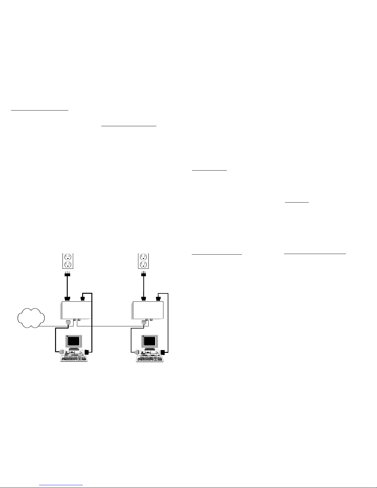
T
ANDEM OPERATION
IPS Tandem Operations requires two specially configured IPSs and a special cable that allows the two units
to communicate with each other. The objective of the
tandem operation is to have one unit ON and the other
OFF at all times. It is primarily used in backup operation scenarios.
The Tandem operates very similar to the standard IPS,
but has a few additional serial port commands. The
main difference in this mode of operation is that
instead of recycling power to the attached device, the
"Main" unit powers OFF and sends a message to the
"Standby Alternate" unit to power ON. If the Standby
Alternate fails to acknowledge the power on command,
the Main will recycle the AC power to its attached
device.
10
If the transferee is acknowledged, the Alternate will
remain powered ON until it resets and the reverse
handshake occurs (powers OFF and tells the Main to
power ON).
The Tandem Mode is enabled with the *TN1 command
and disabled with the *TN0 serial port command.
A power up command (*PUx) is also used with the
Tandem units. The master unit should power ON
(*PU1) when power is applied and the Alternate should
be set to be powered OFF (*PU0). These are stored
commands and will go away if reset.
DIRECT POWER Transferee Methods
Pressing the pushbutton switch on either unit will
cause the power to be transferred to the other unit.
Transferring power can also be accomplished with the
*PRC (Recycle Power) command or by using the Ring
Count Reset feature.
INST
ALLA
TION
Install the IPS TANDEMs according to the diagram
below. Identify the Telco cables with the Red and
Green tape before you begin.
11
CENTRAL
OFFICE
IPS
STANDBY
IPS
MAIN
RS-232 RS-232
MAIN PC
STANDBY PC
Common
Power
Cord
Common
Power
Cord
PC
Extension
Cord
PC
Extension
Cord
(Green) (Red)
IPS SPECIFICATIONS:
Weight 6.9oz (unit); 1lb (ship)
Dimensions 4.5” W x 3” D x 1.25” H
Connectors (2) RJ-11 Telco/Control;
(2) IEC-C13/14 (AC);
(1) DB-9 Female RS-232
LEDs (3) Power, Status
Switches (1) Pushbutton reset
Bell None
Cables (1) 6’ DB-9 Female
(1) 6’ RJ-11Cable
Adaptor None
AC Power 115V/60Hz, 10 Amps to
220V/50Hz, 6.3 Amps
Tandem
Operation
AAwwaarrdd WWiinnnniinngg PPrroodduucctt LLiinnee::
The Stick - 1x4 phone line sharing device
ACP Series - Industrial grade line sharing
device in 3, 5, and 9 ports
Stick II - 2x5 auto call processor
The LineHunter - 4x12 call processor
SR Series - Selective ring call processor
The Power Stone - Call activated AC
power reboot device; Manual and automatic control
Push Button Reset - Reset device for
PC's with ATX style motherboards
 Loading...