

Page 1
Rev 2.0
QSFP-DD
Controller
Manual
MULTILANE SAL
Page 2

QSFP-DD Manual rev2.0
TAB LE OF CONTENTS
Power Supply .......................................................................................................................................... 2
Configuration tab .................................................................................................................................... 2
Monitoring tab ........................................................................................................................................ 4
I2C R/W tab ............................................................................................................................................. 6
EEPROM tab ........................................................................................................................................... 7
1 | P a g e
Page 3
QSFP-DD Manual rev2.0
POWER SUPPLY
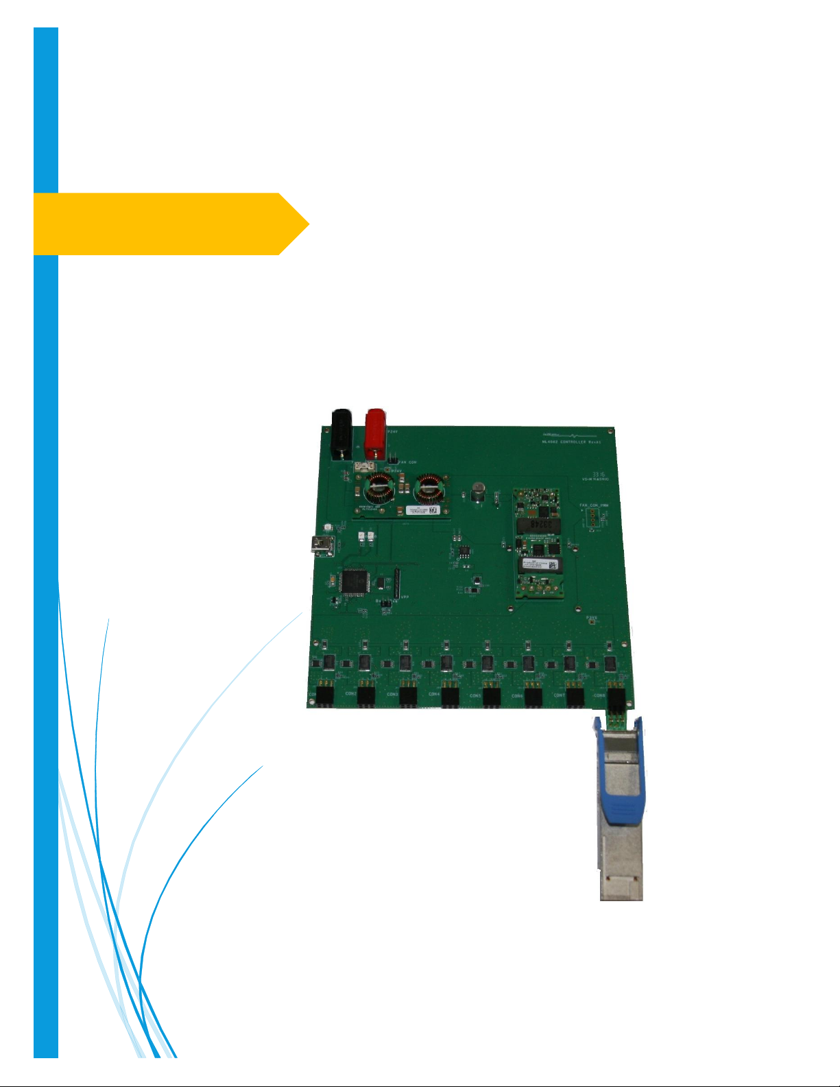
The controller is powered using a 24V external power supply through banana plugs U6, U7.
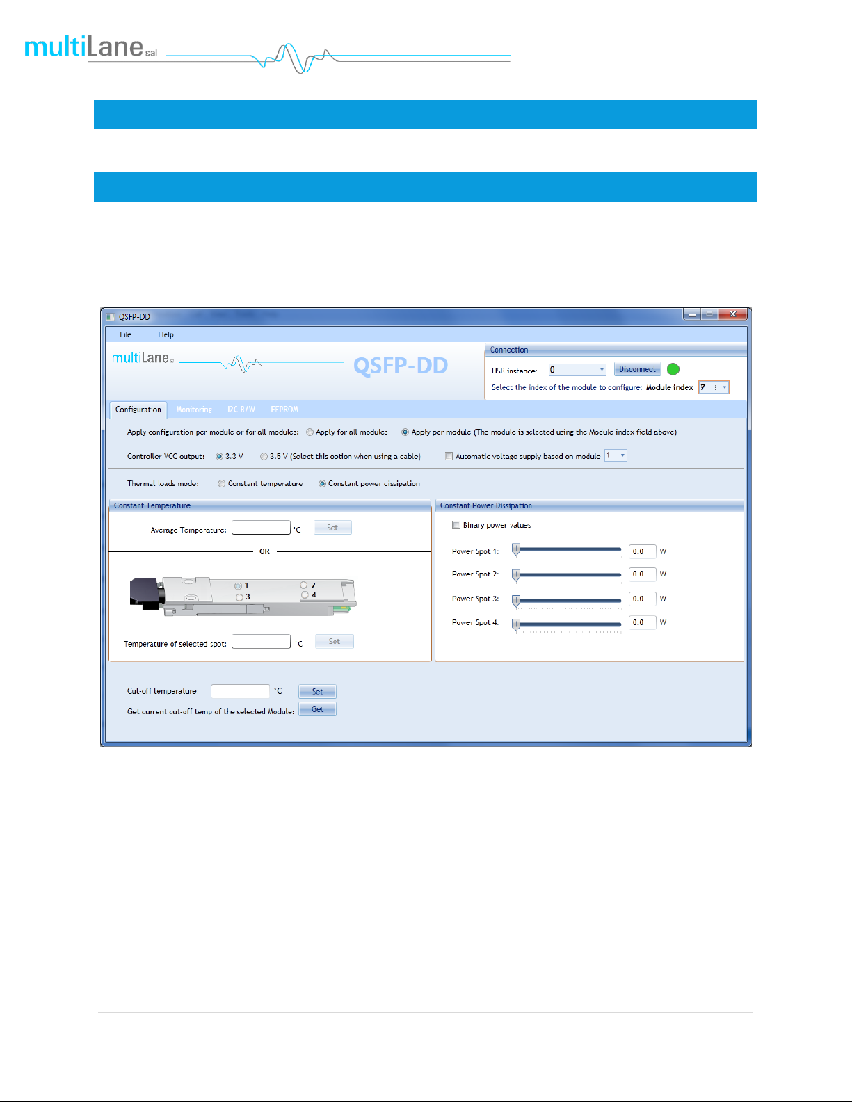
CONFIGU RATI ON TAB
In the Configuration tab, the USB Instance dropdown list is used to select the desired host if you have
many controllers connected to your PC. The Module Index indicates the module of the selected USB
instance that needs to be configured.
1. The configurations in this tab can be set to all modules or per module.
2. Controller Voltage supply output can be set to 3.3 or 3.5 V. Also, it can be automatically set to the
option that gives the closest value to 3.3 V at the module side. To do so, check Automatic voltage
supply based on module x option and select the reference module to base the calculations on. Note
that this option is enabled only when Apply for all modules is selected.
2 | P a g e
Page 4

QSFP-DD Manual rev2.0
3. Two thermal loads modes are available: Constant temperature and Constant power dissipation.
a. Constant temperature
Option 1: Used to fix the total temperature of the module (Enter the temperature value and click Set).
Option 2: Used to fix the temperature of a specified spot in the module (Select the spot that you need to
fix its temperature, enter the temperature value and click Set).
b. Constant Power Dissipation
Used to set the power value of the desired spot using the corresponding slider.
Power spots 1 and 2 are always static. However, power spots 3 and 4 can be programmable (precision
0.1W). When the Binary power values checkbox is checked, spots 3 and 4 will be static.
4. The user can set the temperature cut-off value using the Cut-off temperature field. The current cut-
off temperature could be read using the Get button.
3 | P a g e
Page 5

QSFP-DD Manual rev2.0
MONITORING TAB
This tab displays the temperature values, the voltage sense, the controller VCC and current sense of all
the modules and each of their spots.
Mod Volt sense: Measured voltage sense of the module.
Controller current sense: Measured current sense on the controller.
MPD: Measured power dissipation (Mod Volt sense * Controller current sense).
Controller VCC: Measured voltage on the controller.
Temperature: The temperature values can be logged. The Interval indicates the time spent between
consecutive temperature measurements. And the Total duration indicates the total time of logging
temperature values.
After the logging is done, you can view the graph that shows the temperature in time, cf. figure below.
4 | P a g e
Page 6

QSFP-DD Manual rev2.0
5 | P a g e
Page 7

QSFP-DD Manual rev2.0
I2C R/W TAB
From this tab you can read and write specific registers from the selected page in the memory map.
6 | P a g e
Page 8

QSFP-DD Manual rev2.0
EEPROM TAB
This tab allows user to Load or Save his custom MSA configuration.
Refresh Page button: Read MSA Registers, and refresh values.
Write MSA to HW button: Write the current MSA configuration to QSFP module.
Save MSA to file button: saves the current MSA memory to a file using Comma separated values
(CSV) format.
Load MSA from file button: Loads MSA values from file and map it to MSA memory.
7 | P a g e
Page 9

QSFP-DD Manual rev2.0
Revision
Updates
Date
1.0
Preliminary
17/08/2016
1.1
Remove drawings
Update Cover page
18/08/2016
1.2
Updated pic
28/09/2016
1.3
Updated controller pic
Added graph
30/09/2016
1.4
Added power supply info
21/10/2016
1.5
Configuration tab (power spots)
04/11/2016
1.6
Add current and voltage sense
07/11/2016
2.0
Configuration tab updates
16/11/2016
REVISION INFORMATION
8 | P a g e
 Loading...