

MultiKai Family Compact, Medium, Comercial Large, Deluxe, Jumbo Assembly And Operating Instructions Manual
The MultiKai Cooker is certified by the Australian Gas Association, certificate number
6857. Doug Andrews from New Zealand invented the MultiKai Cookers, which are
covered by Australian Patents 332466 and New Zealand Patent 332466.
ASSEMBLY & OPERATING INSTRUCTIONSASSEMBLY & OPERATING INSTRUCTIONS

Installation Instructions
These instructions are for the Family Compact and Medium Cookers, however they
also apply to the Commercial Large, Deluxe, and Jumbo MultiKai Cookers.
The MultiKai Cookers are designed for use with Universal LPG. They are powered by
either a 2 ring burner model with a Total Nominal Gas Consumption of 12.6MJ/h or a 3
ring burner model with a Total Nominal Gas Consumption of 20.9MJ/h. Please refer to
the Data Label on the upper chamber of the cooker to identify your model.
Gas Connection
The Gas Connection to the burner is a male 1/4” BSP and is situated at the right hand
front of the cookers.
The Cookers must be connected to the gas cylinder with the Flexible Hose & Gas
Regulator supplied with the Cooker. DO NOT USE ANY OTHER HOSE &
REGULATOR. Ensure that the hose does not contact the hot surfaces of the cooker.
The hose should not be subjected to abrasion, kinking or permanent deformation and
should be able to be inspected along its entire length. If a replacement hose or
regulator is required, contact your local MultiKai distributor.
WARNING: Ensure the hose restraint is securely fitted to the gas cylinder on the large,
deluxe and jumbo models so that there is no strain on the gas connections. The chain
should be looped around the handle of the gas cylinder and should remain connected
except when changing or disconnecting the gas cylinder.
Remove all packaging materials before assembling the MultiKai Cooker.
Location
The MultiKai Cooker should be operated in a sheltered, well ventilated, outdoor
environment. Ensure the Multi Kai Cooker is at least 250mm clear of any flammable or
combustible materials and on a level surface. DO NOT OPERATE INDOORS, IN AN
ENCLOSED AREA OR AN INCLINED OR UNEVEN SURFACE.
Chemicals, flammable materials, or spray aerosol cans should not be stored near the
cooker either during use or while in storage. The cooker should also be clear of any
articles either on or leaning against it.
USE OUTDOORS ONLY
This appliance shall only be used in an above ground open-air situation with natural
ventilation, without stagnant areas, where gas leakage and products of combustion
are rapidly dispersed by wind and natural convection.
2
Installation Instructions
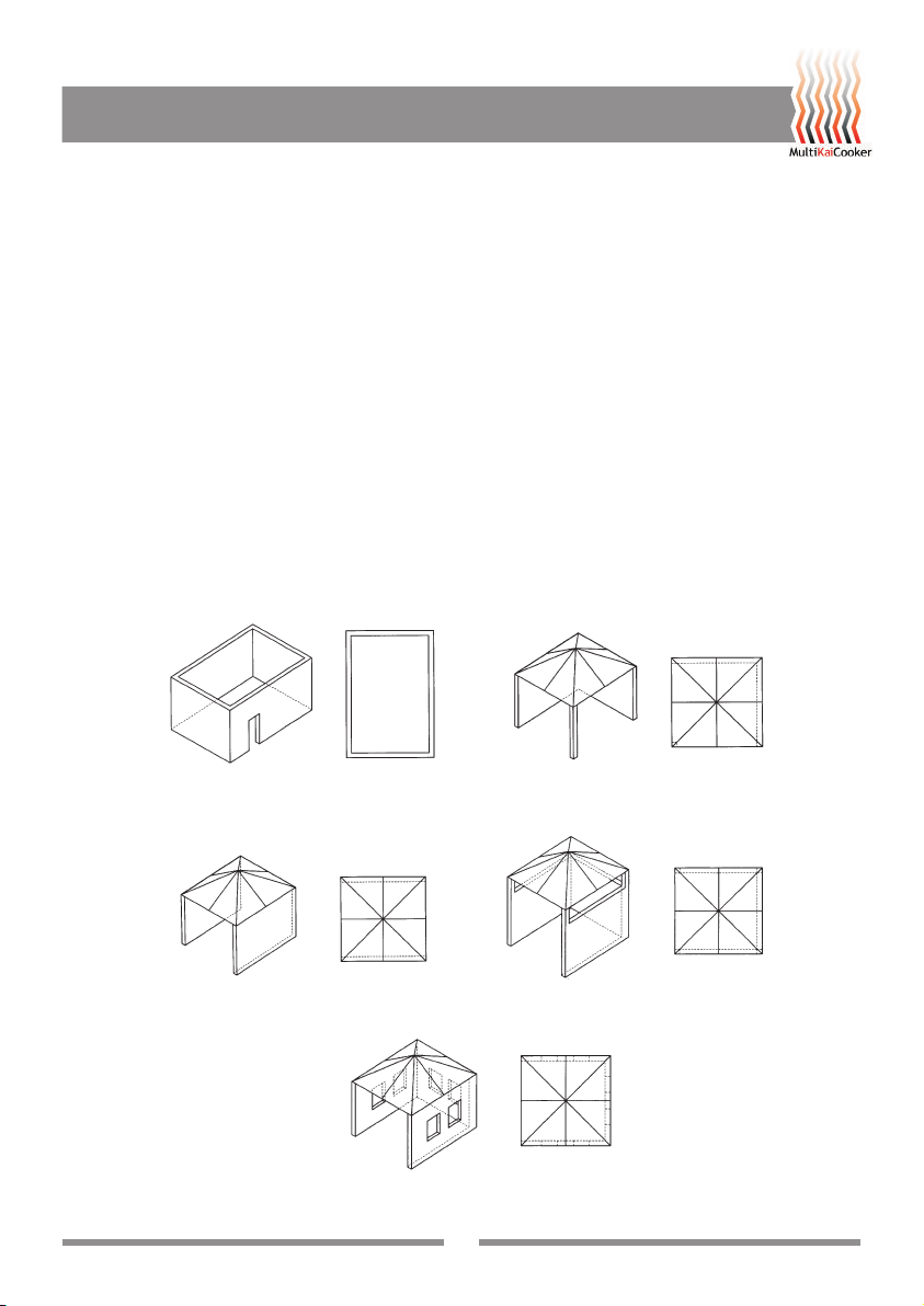
Any outdoor enclosure in which the appliance is used shall comply with one of the
following:
• An enclosure with walls on all sides, but at least one permanent opening at ground
level and no overhead cover. See Figure 1.
• Within a partial enclosure that includes an overhead cover and no more than two
walls. See Figure 2 & 3.
• Within a partial enclosure that includes an overhead cover and more than two walls,
the following shall apply:
- At least 25% of the total wall area is completely open; and
- At least 30% of the remaining wall area is open and unrestricted. See Fig 4 & 5.
• In the case of balconies, at least 20% of the total of the side, back and front wall
areas shall be and remain open and unrestricted.
The following diagrams provide a diagrammatic representation of outdoor areas.
Rectangular areas have been used in these figures - the same principles apply to any
other shaped area.
Figure 1 - Enclosure with walls on all sides but
Figure 3 - Partial Enclosure with overhead cover and
no overhead cover.
no more than two walls.
Figure 5 - Open side at least 25% of total wall area. 30 percent
or more in total of the remaining wall area is open and unrestricted.
Figure 2 - Partial Enclosure with overhead cover and
Figure 4 - Open side at least 25% of total wall area.
30 % or more in total of the remaining wall area is
no more than two walls.
open and unrestricted.
3
6
543
WARNING
1
2
DO NOT SPRAY AEROSOLS IN THE VICINITY OF
THIS APPLIANCE WHILE IT IS IN OPERATION.
DO NOT STORE OR USE FLAMMABLE LIQUIDS OR
ITEMS IN THE VICINITY OF THIS APPLIANCE.
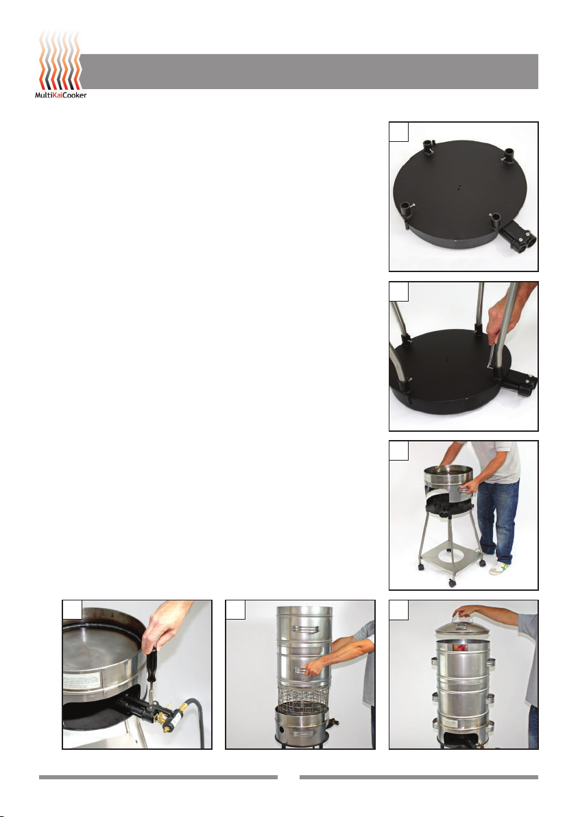
Assembly
These assembly instructions specifically refer to the
Family size cookers, however, similar procudures apply
to the Commercial cookers.
1. Place Burner Tray face down on the ground with leg
sockets facing up.
2. Push legs downwards into leg sockets. This will
require a bit of force to ensure the stand fits level
when the legs are firmly seated. Use a spanner or
Allen key to tighten the screws on all four legs.
3. Turn the stand upright and then place hot plate
chamber on top.
4. Screw the gas valve assembly onto the end of the
burner with a phillips head screw driver.
5. Fit the baskets, followed by the chambers. Note:
Compact cooker has 2 baskets & 1 chamber,
Medium Cooker has 4 baskets and 2 chambers.
6. Fit the lid and press down so that it clicks into place.
Assembly Instructions
4

Assembly Instructions
8
7
7. Fit guard to the locating holes in the burner tray.
8. To fit your 9kg gas cylinder to the base, tilt the
cylinder horizontally and feed it through the legs of
the stand at the lowest point. Then rotate the gas
cylinder upwards and allow it to locate in the hole.
Attach the regulator to the gas cylinder.
Testing
Before each use, check all connections for gas leaks with
soap and water. DO NOT use a naked flame for detecting
leaks. Inspect the gas hose for any abrasion, kinking,
permanent deformation, splits or holes. Replace hose
immediately if damaged.
WARNING: The castors must be locked when the
MultiKai Cooker is in use. Do not leave the cooker
unsupervised when in use. Ensure that children are kept
away from the cooker when in use and that they do not
touch the hot surfaces. To ensure personal safety, do not
ignite the burner while wearing loose fitting items of
clothing than can drape over the burner and ignite.
Then
rotate
Feed in first
Lighting Instructions
1. Remove the hotplate so that there is clear access to the burner.
2. Set Gas Valves to ‘OFF’ position, then turn on the gas cylinder valve.
3. Ignite the gas lighter supplied and place over the outer ring burner.
4. With the gas light still ignited, turn the outer ring gas valve to high. Ensure your
face, arms or any loose items of clothing are not over the burner.
5. Turn inner ring gas valve/s on as required once outer ring has ignited.
6. Place the hotplate over the burner.
Abnormal Operation
Any of the following are considered abnormal operation and may require servicing:
- Burners not igniting properly. - Gas Valves which are difficult to turn.
- Burners failing to remain alight. - Yellow luminous flames.
In case the appliance fails to operate correctly, please contact MultiKai.
WARNING: Servicing should be carried out only by authorised personnel.
5

Using your MultiKai Cooker
21417
3710911
Step by Step Instructions on how to cook a Hangi
1. Two options: Place either fresh or semi frozen meat
portions in the bottom baskets (pork, chicken, lamb,
beef) and vegetables in the top baskets.
2. Heat the hot plate and place 1/4 teaspoon of Manuka
Wood Chips onto the middle of the plate.
3. Stack the baskets on top of the Hotplate.
4. Then place the Chambers & Lid over the baskets.
5. Turn your burner on full for the first 15 mins of the
smoking process to allow the Manuka Wood Chips to
line the food.
NOTE: Do not lift lid during the smoking process as
only a small amount of Manuka is used to achieve
that “Beautiful Flavour”.
6. At the end of the smoking period, off the inner burner.
7. Remove the lid and add water.
CAUTION: When opening the lid, open away from
the body and face to protect from heat and steam.
6

Using your MultiKai Cooker
8
8. If you are using fresh meat portions, add approx 2-3
cups of water after the smoking process is
completed. When using semi frozen meat portions,
you may need to add 1 cup of water to quicken the
thawing process.
You may need to adjust your heat depending on the
outside temperature.
9. Put the lid back on making sure it clicks back in place
to hold the pressure in.
10. After approximately 30 minutes, check the water level
to make sure there is enough juices in the bottom of
the hotplate to prevent burning. Carefully knock each
handle of the Chamber upwards to crack the seal to
the hotplate and rock from left to right until you can
raise the chamber freely.
11. Check that there is enough liquid in the bottom of the
hotplate. You may need to add more water or turn
down the heat. Once checked, lower the upper
chamber back down over the hotplate chamber to reseal.
12. You should check every 20-30 minutes to ensure that
the liquid does not evaporate and burn as this will
taint the food. If the liquid evaporates too quickly,
then add more water and turn the burner down until
the liquid is just bubbling. By a combination of
adjusting the heat and adding more liquid, you should
be able to maintain the ‘bubbling’ liquid. If you add
too much liquid, the effect will be that the food is
more steamed than roasted.

Using your MultiKai Cooker
14
13. After 1 - 2 hours of cooking the liquid on the hot plate
will begin to thicken, giving a dryer heat for the final
roasting stage. At this point it is important to keep
checking that the gravy doesn’t burn, if so add a little
more water.
14. At the completion of the cooking cycle, remove the
upper chamber/s and baskets from the MultiKai.
Serve up the food and enjoy the wonderful taste!
Cooking Times
The cooking time for the compact cooker is approximately 1-2 ½ hours, and medium
cooker is 2½ - 4 hours. Cooking times will vary depending on the ambient
temperature, whether the cooker is in the sun or shade, whether the air is still or
breezy, how much food is in the baskets, etc. When first using the MultiKai Cooker, it is
important to keep looking at the food and the liquid on the hotplate. Like all cooking,
the more experience you have, the better the result.
NOTE: These steps are critical for the success of your Hangi.
8

Using your MultiKai Cooker
Experiment with your Hangi
The wonderful thing about the MultiKai Cooker is that you can experiment, such as:
1. You can wrap your food in tin foil and pour water on the base to steam cook.
2. Try poking holes in the top of the tin foil parcel using a fork. Place a tablespoon of
Manuka Wood Chips on the hot plate and smoke for approximately half an hour
before adding water to steam cook your food.
3. Try lining the baskets with watercress or cabbage leaves before placing the food
in. Place rocks or soil onto the hot plate. Try different types of wood for the
smoking process (peach wood, taraire).
Helpful Hints
• The MultiKai Cooker is a low pressure cooker, so the more food in the chamber
the better the cooking time. We recommend that the baskets to be no less than
half full of food.
• Use portioned meat, and no less than 10 pieces for the compact and medium
cookers.
• Soak muslin cloth in water and place on top of the vegetables or ice cubes
wrapped in muslin cloth.
• Because of the heat levels in the cooker, always place the meat in the bottom
baskets and vegetables in the top baskets. Always place stuffing and steam
puddings in the top basket.
• When the 2 ring burner is lit, the flame should burn clean and blue. A yellow flame
has less heat and will blacken the underside of the hot plate.
• Don’t be afraid to lift your housing after the smoking process. It is important to see
the different stages while your Hangi is cooking. The good thing about this MultiKai
Cooker is that the food will eventually cook, no matter how many times your lift the
housings and the lid.
• Always clean cooker after every cook up. Scrape and clean out base and then add
2 cups of water and detergent. Reassemble your cooker and heat the hot plate to
steam clean the baskets, inner housing and lid. Drain and dry off the liquid from
the hot plate and rinse. Light the burner for a short time to dry the cooker. When
cool, add a bit of oil to protect the plate ready for your next cook up. If your
dishwasher is large enough, you can place the baskets, lid and chambers in the
dishwasher.
9

Recipes
No-Fuss Steam Pudding
Ingredients
• ½ cup sugar (burnt) • 1 cup sugar
• ½ cup water-mixture • 200 grams butter
• 2 cups flour • 2 eggs
• 1 tablespoon bi-carbonate soda
Method
Burn sugar mixture: Place ½ cup sugar in a pot and burn on high heat until the sugar
mixture is black. Remove from the stove and slowly add ½ cup water. Leave to cool for
approximately 10 minutes.
Pudding mixture: Place flour, sugar, soda, melted butter, eggs and burnt sugar mixture
into a bowl. Mix together with a whisk or wooden spoon. Well grease a metal container
and pour in the mixture. Cover with tin foil and poke a few holes. Place container in the
vegetable basket with the vegetables and cook for the entire time as the Hangi.
Smoking Fish
Preparation
This is a hot smoker so for best results, salt the fish first and place in the fridge for 1-2
days or leave in the sun for 2 to 4 hours before smoking.
1. Cover the entire hot plate with aluminium foil (helps to keep the hot plate clean).
Place approximately 1 cup of Manuka Wood Chips in the centre of the foil.
2. Place the fish in baskets skin down and cook for approximately 30 to 40 minutes
(depending on the size of cooker). Leave lid fully on.
Fresh Fish: Paste fish with golden syrup and sprinkle with lemon pepper. Place fish in
baskets skin down for approx. 30-40 minutes (depending on the size of cooker).
10

Recipes
No-Fuss Rewena Bread
Ingredients
• 5 cups plain white flour • 3/4 cup sugar
• 4 cups of warm water • 7 tablespoons Surebake yeast
• 3-4 cups flour
Method
Place the flour and Surebake yeast in a large bowl. Add
warm water and mix together. Cover the mixture with a
tea towel. Allow to sit in a warm place for the mixture to
double in size. Time will vary depending on the
temperature of where the mixture is placed.
When ready add 3-4 cups of flour and mix together with
a knife. Turn out onto a well floured surface and knead
dough until dough has a smooth texture, approximately 10 minutes, adding more flour
to the surface if needed. Shape dough into a non stick loaf pan big enough to fit inside
your first basket. Heat MultiKai Cooker with the housing and lid on until nice and hot.
Place basket with loaf tin onto the hot plate and cook on 3/4 heat for approx 40
minutes. When cooked, tip the loaf of bread out of the tin and turn upside down onto
the basket for a further 5 minutes to brown the top. Cut into slices and eat with
whatever you like.
Coconut Crabs
Use fresh crabs, once they have been in the fridge for a day or two, they just don’t
taste as good and the meat is soft and watery.
In the bottom of the MultiKai Cooker, place:
• 1 sliced onion • 2 tablespoons of freshly chopped chilli
• Handful of sliced spring onions • 1 cup of white wine
• 2 tablespoons of fresh ginger • 1 cup of water
Method
Place fresh crabs into the baskets inside the MultiKai Cooker and steam cook for
approx 6-7 minutes leaving them just undercooked. Remove crabs from the baskets.
Add one can of coconut to the steaming liquid. Take the tops off the crabs and remove
the gills. Cut into 1/4 and place them in the coconut cream. Simmer for 3 minutes.
Serve and eat with your fingers. Oh, what tasty fun!!
11

Warranty
Where the appliance has been used solely for domestic, private or household purposes
within Australia or New Zealand, MultiKai will repair, or at its option replace the
appliance if it is found to be defective due to faulty materials or workmanship within one
year of its purchase. Where the appliance has been used commercially, this warranty
only applies for a period of 90 days from purchase.
Gas regulators are provided with all gas appliances as part of an Australian Gas
Association requirement and carry a 12 month warranty only.
This warranty does not cover defect caused by:
(a) Unauthorised alterations, modifications or repairs to the appliance.
(b) Incorrect installation or maintenance of the appliance.
(c) Use of the appliance not in accordance with the instructions supplied for its use.
(d) Unauthorised substitution, impact, misuse or negligence.
The occurrence of any one or more of which will render this warranty void. This
warranty is subject to the purchaser providing satisfactory proof of purchase of the
appliance to MultiKai.
Service and spare parts
If the appliance fails to operate correctly, never attempt to repair the appliance yourself.
Repairs by unskilled persons may cause damage and accidents. First refer to the
contents of this manual. If you do not find the necessary information, contact your
nearest MultiKai Service Center.
Servicing work on this appliance must be carried out by Authorised Personnel.
Always request the use of original spare parts.
For Sales, Service & Spare Parts please contact:
New Zealand:
MultiKai NZ
29 Commerce Street, Whangarei
PO Box 6006, Otaika, Whangarei
Phone: 09 438 1484
Free Phone: 0800 66 44 99
Email: doug.andrews@xtra.co.nz
Website: www.multikaicooker.co.nz
Australia:
MultiKai Australia Pty Ltd
Unit 22, 22-30 Wallace Avenue
Point Cook Victoria 3030
Phone: 03 9369 9989
Fax: 03 9369 8813
Email: info@multikai.com.au
Website: www.multikai.com.au
12
 Loading...