

Multihog CX75 Installation Instructions Manual
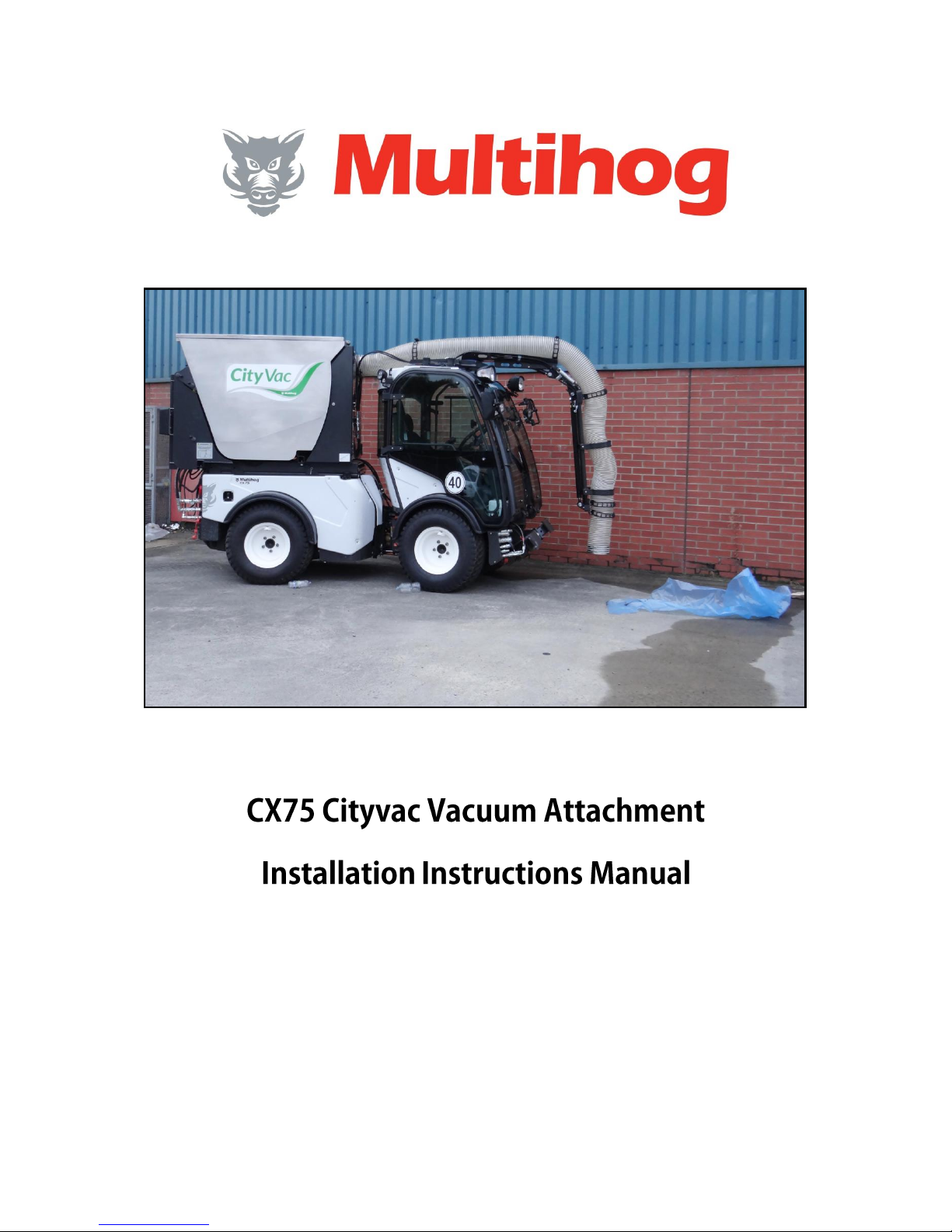
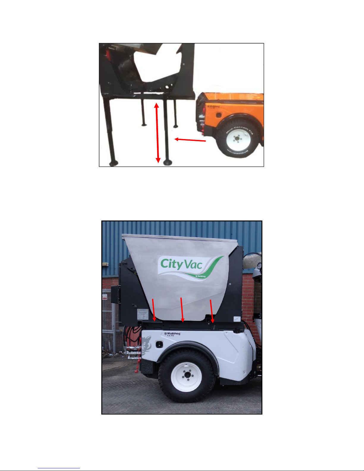
FIG. 1
Ensure the attachment stands are high enough to clear the load rails on the machine while
reversing into position (fig 1). Be careful not to reverse into the attachment while lining load
rails up with the attachment frame.
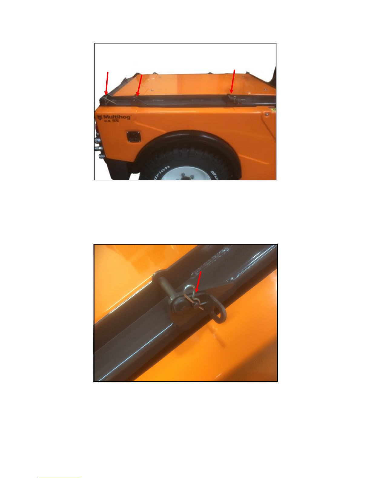
FIG. 2
When the attachment is on the rails ensure the pins supplied are put in the three positons
on either side of the load bed. Fig. 2
FIG. 3
Lock pin in place as shown above in Fig. 3 with R- key supplied.
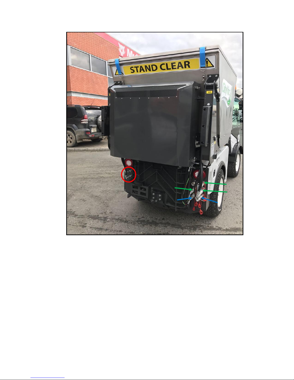
FIG.4
When connecting the attachment hoses to the Auxiliary ports on the rear of the machine
note as stated below where each hose goes in Fig. 4 above.
1. (HPCO) The two hoses on the rear LHS highlighted in red are the oil feed and return
for the high pressure carry over.
2. (Motor) The three hoses highlighted in green on the rear RHS are for the oil supply,
return and case drain for the fan motor. These are all different sizes and coupling
types and will therefore only connect one way.
3. (Tip CYL.) The two bottom hoses on the rear RHS (Blue) are the oil supply and return
to the tipping cylinders.
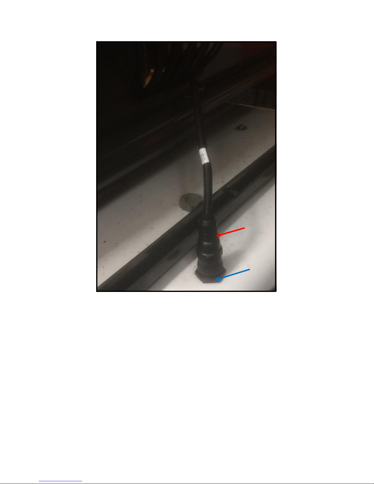
FIG. 5
Plug rear attachment loom into socket on the front of the CX rear chassis. The loom (red)
and socket (blue) are shown above in Fig. 5. This supplies power to the solenoids on the
valve block on the rear attachment.

FIG. 6
When mounting the front trunk on the cab of the machine, use lifting points shown above in
Fig. 6 to lift the attachment safely. Use adequately specified shackles and crane to lift and
secure the trunk safely also.
 Loading...